WO2022124153A1 - ロボット制御装置、ロボット制御システム及びロボット制御方法 - Google Patents
ロボット制御装置、ロボット制御システム及びロボット制御方法 Download PDFInfo
- Publication number
- WO2022124153A1 WO2022124153A1 PCT/JP2021/044048 JP2021044048W WO2022124153A1 WO 2022124153 A1 WO2022124153 A1 WO 2022124153A1 JP 2021044048 W JP2021044048 W JP 2021044048W WO 2022124153 A1 WO2022124153 A1 WO 2022124153A1
- Authority
- WO
- WIPO (PCT)
- Prior art keywords
- setting
- robot control
- setting information
- unit
- control device
- Prior art date
- Legal status (The legal status is an assumption and is not a legal conclusion. Google has not performed a legal analysis and makes no representation as to the accuracy of the status listed.)
- Ceased
Links
Images



Classifications
-
- B—PERFORMING OPERATIONS; TRANSPORTING
- B25—HAND TOOLS; PORTABLE POWER-DRIVEN TOOLS; MANIPULATORS
- B25J—MANIPULATORS; CHAMBERS PROVIDED WITH MANIPULATION DEVICES
- B25J9/00—Program-controlled manipulators
- B25J9/16—Program controls
- B25J9/1679—Program controls characterised by the tasks executed
- B25J9/1689—Teleoperation
-
- H—ELECTRICITY
- H04—ELECTRIC COMMUNICATION TECHNIQUE
- H04L—TRANSMISSION OF DIGITAL INFORMATION, e.g. TELEGRAPHIC COMMUNICATION
- H04L12/00—Data switching networks
- H04L12/28—Data switching networks characterised by path configuration, e.g. LAN [Local Area Networks] or WAN [Wide Area Networks]
- H04L12/46—Interconnection of networks
- H04L12/4641—Virtual LANs, VLANs, e.g. virtual private networks [VPN]
-
- B—PERFORMING OPERATIONS; TRANSPORTING
- B25—HAND TOOLS; PORTABLE POWER-DRIVEN TOOLS; MANIPULATORS
- B25J—MANIPULATORS; CHAMBERS PROVIDED WITH MANIPULATION DEVICES
- B25J9/00—Program-controlled manipulators
- B25J9/16—Program controls
-
- Y—GENERAL TAGGING OF NEW TECHNOLOGICAL DEVELOPMENTS; GENERAL TAGGING OF CROSS-SECTIONAL TECHNOLOGIES SPANNING OVER SEVERAL SECTIONS OF THE IPC; TECHNICAL SUBJECTS COVERED BY FORMER USPC CROSS-REFERENCE ART COLLECTIONS [XRACs] AND DIGESTS
- Y02—TECHNOLOGIES OR APPLICATIONS FOR MITIGATION OR ADAPTATION AGAINST CLIMATE CHANGE
- Y02P—CLIMATE CHANGE MITIGATION TECHNOLOGIES IN THE PRODUCTION OR PROCESSING OF GOODS
- Y02P90/00—Enabling technologies with a potential contribution to greenhouse gas [GHG] emissions mitigation
- Y02P90/02—Total factory control, e.g. smart factories, flexible manufacturing systems [FMS] or integrated manufacturing systems [IMS]
Definitions
- the present invention relates to a robot control device, a robot control system, and a robot control method for setting a virtual local area network (hereinafter referred to as VLAN) in a network connecting a plurality of robots with a concentrator.
- VLAN virtual local area network
- Patent Document 1 describes a computer system for a production line in which factory equipment having the same role as a concentrator such as a hub is assigned to the same VLAN and data is efficiently distributed in the production line network.
- the factory equipment includes a computer connected to the robot arm to control the robot arm.
- a robot control system in which a plurality of robots are connected by a line concentrator, there is a function of communicating between the robots by Ethernet (registered trademark) to prevent interference between the robots or to synchronize the operation of the robots. At this time, it is desirable that the communication data be transmitted and received as smoothly as possible. However, if you try to communicate at high speed, the traffic on the network will increase. As a result, the data may not arrive and may be omitted, or the data may need to be resent. In a robot control system in which a virtual LAN is set in a network that connects multiple robots with a concentrator, data transmission can be performed smoothly by using broadcast and communicating only between the necessary robots. can. However, if the work changes, the combination of the plurality of robots changes, so it is desired that the combination of the plurality of robots changes according to the work and communication is performed only between the necessary robots.
- Ethernet registered trademark
- the first aspect of the present disclosure is a robot control device connected to a concentrator and forming a virtual local area network with at least one other robot control device connected to the concentrator.
- a setting unit for setting a plurality of setting information of the virtual local area network and A storage unit that stores a plurality of setting information set by the setting unit, and a storage unit.
- a second aspect of the present disclosure is between a plurality of robot control devices for controlling a plurality of robots and at least two robot control devices connected to the plurality of robot control devices. It is a robot control system equipped with a concentrator that can configure a virtual local area network.
- the robot control device of one of the at least two robot control devices includes a setting unit for setting a plurality of setting information of the virtual local area network and a storage unit for storing a plurality of setting information set by the setting unit.
- a transmission unit that transmits setting request information to the setting information selected from the plurality of setting information to the concentrator.
- the concentrator is a robot control system that sets the virtual local area network between the at least two robot control devices based on the setting request information.
- a third aspect of the present disclosure is between a plurality of robot control devices for controlling a plurality of robots and at least two robot control devices connected to the plurality of robot control devices. It is a robot control method of a robot control system equipped with a concentrator that can configure a virtual local area network.
- the robot control device of one of the at least two robot control devices is Set multiple setting information of the virtual local area network, Memorizes multiple set setting information and The setting request information to the setting information selected from the plurality of setting information is transmitted to the concentrator.
- the line collecting device is It is a robot control method in which the virtual local area network is set between the at least two robot control devices based on the setting request information.
- the combination of a plurality of robots can be changed according to the work, communication can be performed only between necessary robots, and the amount of communication between robots can be reduced.
- FIG. 1 is a block diagram showing a robot control system according to the first embodiment of the present disclosure.
- the robot control system 10 includes a hub (HUB) 100 that serves as a line concentrator, and six robots 200 to 700 that are LAN-connected via the hub 100.
- Robots 200 to 700 are connected to ports P1 to P6 of the hub 100.
- FIG. 1 shows an example in which four robots 200 to 500 and two robots 600 and 700 are divided into networks by a hub 100, and two independent VLANs are configured.
- the robot control system 10 has a function of communicating between robots by Ethernet (registered trademark), preventing interference between robots, or synchronizing robot operations.
- Ethernet registered trademark
- the robot 200 serves as a leader, and the other three robots 300 to 500 operate following the movement of the robot 200, whereby four robots are used. It is possible to realize the transfer of the work by the robots 200 to 500 of the above. In this case, the leader robot 200 transmits data necessary for the follow-up operation to the other three robots 300 to 500.
- a VLAN is configured between the four robots 200 to 500 and communication is performed only by the four robots 200 to 500.
- the combination of robots also changes, and there are cases where you want to change the combination of robots.
- the robot 200 may serve as a leader, and the other two robots 400 and 500 may follow the movement of the robot 200 to perform work.
- the robot 400 and the robot 500 may cooperate with each other to perform another work.
- the robot 200 serves as a reader and the robot 200 issues a command to the hub 100 to change the VLAN setting to set a combination of robots for data communication will be described.
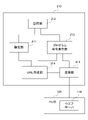
- FIG. 2 is a block diagram showing a configuration of a part of the robot control device and the hub included in the robot.
- the robot control device 210 includes a mechanism for causing the robot to perform work, but it is omitted in FIG.
- the robot control device 210 may be provided separately from the robot, but in the present embodiment, the robot 200 will be described as including the robot control device 210.
- the robot control device 210 includes a setting unit 211, a storage unit 212, a program instruction execution unit 213, a URL creation unit 214, and a transmission unit 215.
- the transmission unit 215 communicates with the hub 100 provided with the web server 110.
- the setting unit 211 is, for example, a teaching operation panel provided with a liquid crystal display device with a touch panel, and displays a setting screen for inputting VLAN setting information to the liquid crystal display device.
- the setting unit 211 stores a plurality of VLAN settings for a plurality of combinations of the four robots 200 to 500 in the storage unit 212.
- the setting unit 211 stores in the storage unit 212 two combinations of the robots that set the VLAN in order to perform the first work and the second work by the four robots 200 to 500.
- the first work is a work in which the robot 200 serves as a leader and the other three robots 300 to 500 follow the movement of the robot 200.
- the second work is a work in which the robot 200 serves as a leader and the other two robots 400 and 500 follow the movement of the robot 200.
- the setting unit 211 sets the VLAN setting number (referred to as the setting number SN1), which is the data associated with the program performing the first work, and the VLAN setting, which is the data accompanying the program performing the second work. Number (set number SN2) is stored.
- the setting unit 211 displays a setting screen for setting the setting information of the VLAN for the hub 100 according to the instruction of the user.
- the user performs the following operations in order to input the setting information of the VLAN of the first work on the setting screen.
- the selected port multiple VLAN will be described as an example of the VLAN, but the present invention is not particularly limited to the selected port multiple VLAN, and other VLANs such as the port VLAN may be used.
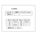
- the user sets the VLAN mode to the selection port multiple VLAN and sets the port P1 of the hub 100 to the uplink VLAN (UV-A), so that the group of the ports P1 is set to UV-A.
- UV-A uplink VLAN
- the setting unit 211 stores the input VLAN setting information of the first work and the setting number SN1 which is the data attached to the program for executing the first work in the storage unit 212 in association with each other. do.
- the uplink VLAN is a VLAN for connecting a shared device such as a hub
- the client VLAN is a VLAN for connecting a machine or device such as a robot that restricts communication with each other. Communication is possible between port P1 belonging to the uplink VLAN and ports P2 to P4 belonging to the client VLAN, but communication is not possible between ports P2 and P4 belonging to the client VLAN.
- the setting unit 211 clears the setting information of the VLAN of the first work of the setting screen according to the instruction of the user. After that, the user performs the following operation in order to input the setting information of the VLAN of the second work on the setting screen.
- the user sets the VLAN mode to the selection port multiple VLAN and sets the port P1 of the hub 100 to the uplink VLAN (UV-A), so that the group of the ports P1 is set to UV-A.
- the group of the port P3 and the port P4 is set as the CV-A1.
- the setting unit 211 stores the input setting information of the VLAN of the second work and the setting number SN2 which is the data attached to the program for executing the second work in the storage unit 212 in association with each other. do.
- the program instruction execution unit 213 Before instructing the execution of the program, the program instruction execution unit 213 requests the VLAN corresponding to the setting number (for example, the setting number SN1) of the VLAN, which is the data attached to the program to be executed, to the URL creation unit 214. Output to.
- the program instruction execution unit 213 stores a setting number SN1 that is data associated with the program that performs the first work and a setting number SN2 that is data associated with the program that performs the second work.
- the hub 100 When the hub 100 is provided with the web server 110 inside, it is possible to transmit the VLAN setting information from the storage unit 212 by designating and transmitting a special URL that is the setting request information from the robot control device 210. Become.
- the hub 100 has a receiving unit that receives a URL from the robot control device 210, but the receiving unit is usually provided by the web server 110, and thus the description thereof will be omitted.
- the URL creation unit 214 creates a URL, which is a data method for transmitting the setting information of the VLAN corresponding to the setting number SN1 stored in the storage unit 212 to the hub 100, and outputs the URL to the transmission unit 215.
- the transmission unit 215 transmits the URL as setting request information to the hub 100.
- the hub 100 includes a web server 110, and the web server 110 analyzes the received URL and sets the VLAN of the hub 100 based on the VLAN setting information acquired from the storage unit 212 based on the analyzed URL. conduct.
- the hub is provided with a web server inside, a special URL is specified from the robot control device, and the VLAN setting information is transmitted from the storage unit, but the robot control device is transferred to the hub.
- the setting method for this is not limited to this.
- the setting information of the VLAN may be included directly in the setting request information without creating the URL.
- the program command execution unit 213 starts the operation of the robot 200 according to the program, and also gives a synchronization (following) operation start instruction to the robots 300 to 500 via the transmission unit 215 and the hub 100. Further, the program instruction execution unit 213 sends operation information to the robots 300 to 500 via the transmission unit 215 and the hub 100 while operating the robot 200 according to the program.
- the robot control device 210 includes an arithmetic processing unit such as a CPU (Central Processing Unit). Further, the robot control device 210 is temporarily used by an auxiliary storage device such as an HDD (Hard Disk Drive) that stores various control programs such as application software or an OS (Operating System), or an arithmetic processing device for executing a program. It also has a main storage device such as a RAM (Random Access Memory) for storing the required data.
- arithmetic processing unit such as a CPU (Central Processing Unit).
- the robot control device 210 is temporarily used by an auxiliary storage device such as an HDD (Hard Disk Drive) that stores various control programs such as application software or an OS (Operating System), or an arithmetic processing device for executing a program. It also has a main storage device such as a RAM (Random Access Memory) for storing the required data.
- a main storage device such as a RAM (Random Access Memory) for storing the required data.
- the arithmetic processing device reads the application software or the OS from the auxiliary storage device, and while deploying the read application software or the OS to the main storage device, the arithmetic processing based on these application software or the OS is performed. Do it. Further, based on the calculation result, various hardware included in each device is controlled. Thereby, the functional block of this embodiment is realized. That is, this embodiment can be realized by the cooperation of hardware and software.
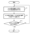
- FIG. 5 is a flowchart showing an operation from the display of the setting screen by the setting unit to the storage of the setting information of the VLAN in the storage unit.
- step S11 the setting unit 211 displays a setting screen for setting the VLAN setting information for the hub 100 according to the user's instruction.
- step S12 the setting unit 211 associates the VLAN setting information of the work input by the user with the VLAN setting number, which is the data attached to the program for executing the work, to the storage unit 212.
- step S13 the setting unit 211 determines whether or not the setting information of the next VLAN is input, and if the setting information of the next VLAN is input, returns to step S11 and the setting information of the next VLAN is input. If it is not entered, the process ends.
- the setting unit 211 can determine whether or not the next VLAN setting information is input, depending on whether or not the user has cleared the VLAN setting information of the first operation of the setting screen.
- FIG. 6 is a flowchart showing an operation until the program instruction execution unit outputs a VLAN setting request and the transmission unit transmits the setting request information to the hub.
- the program instruction execution unit 213 has a setting number based on a VLAN setting number (for example, setting number SN1) which is data accompanying the program to be executed before instructing the execution of the program.
- the VLAN setting request corresponding to SN1 is output to the URL creation unit 214.
- step S15 the URL creation unit 214 creates a URL, which is a data method for transmitting the setting information of the VLAN corresponding to the setting number SN1 stored in the storage unit 212 to the hub 100, and outputs the URL to the transmission unit 215. do.
- the transmission unit 215 transmits the URL as setting request information to the hub 100.
- the setting unit stores the input work VLAN setting information and the VLAN setting number, which is data attached to the program for executing the work, in the storage unit in association with each other.
- the VLAN setting number that is the data attached to the program in this way, even if the program is copied and modified, the VLAN setting number is copied together with the modified program.
- the setting unit uses the VLAN setting number, which is the data attached to the program for executing the work, as the information associated with the input work VLAN setting information. It is not limited to information, and may be, for example, a program number for executing work.
- the program instruction execution unit outputs a setting request to the VLAN corresponding to the number of the program to be executed to the URL creation unit before instructing the execution of the program.
- the VLAN setting information corresponding to the VLAN setting number is read from the storage unit 212. And output to the URL creation unit 214.
- the setting unit 211 reads the VLAN setting information from the storage unit 212 and outputs it to the URL creation unit 214 based on the user's instruction.
- FIG. 7 is a block diagram showing a configuration of a second embodiment of the robot control device included in the robot.
- the robot control system in this embodiment is the same as the robot control system shown in FIG.
- the robot control device 210A includes a setting unit 211, a storage unit 212, a URL creation unit 214, and a transmission unit 215.
- the robot control device 210A does not have the program instruction execution unit 213, and the operation of the setting unit 211 is different.
- the setting unit 211 displays a setting screen for inputting the setting information of the work VLAN of the robot to the hub 100 according to the instruction of the user, and the setting information of the work VLAN input by the user and the work VLAN. It is stored in the storage unit 212 in association with the combination number of the combination of robot connections according to the setting of.
- the VLAN setting information of the work input by the user is stored in the storage unit in association with the VLAN setting number, which is the data attached to the program, but in the present embodiment, it is stored. It is stored in the storage unit 212 in association with the combination number of the combination of robot connections according to the setting of the work VLAN.
- the setting unit 211 stores two combinations in the storage unit 212 in order to perform the first work and the second work by the four robots 200 to 500, as in the first embodiment. explain. In the following description, only the operation different from the first embodiment will be described.
- the setting unit 211 displays a setting screen for setting the VLAN setting information for the hub 100 according to the user's instruction, and the VLAN setting information of the first work input by the user and the first.
- the combination number (referred to as the combination number N1) of the combination of the robot connections according to the setting of the VLAN of the work is linked and stored in the storage unit 212.
- the setting unit 211 displays a setting screen for setting the VLAN setting information for the hub 100 according to the instruction of the user, and the setting information of the VLAN of the second work input by the user and the second operation.
- the combination number (referred to as the combination number N2) of the combination of the robot connections according to the setting of the VLAN of the work 2 is associated and stored in the storage unit 212.
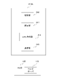
- the setting unit 211 displays a selection screen for selecting a plurality of combinations of the four robots 200 to 500 stored in the storage unit 212 according to the user's instruction.
- the combination numbers N1 and N2 and the connection relationship between the port and the robot are shown.
- the setting unit 211 requests the setting information of the VLAN corresponding to the combination number N1 or the combination number N2 selected by the user to the URL creation unit 214. Output to.
- the URL creation unit 214 creates a URL, which is a data method for transmitting the VLAN setting information corresponding to the combination number N1 or the combination number N2 stored in the storage unit 212 to the hub 100, and outputs the URL to the transmission unit 215. do.
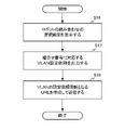
- FIG. 8 is a flowchart showing an operation until the setting unit outputs a VLAN setting request and the transmission unit transmits the setting request information to the hub.
- the operation of storing the VLAN setting information input to the setting screen by the setting unit of the robot control device 210A in the storage unit is performed except that the setting number of the VLAN, which is the data accompanying the program, is replaced with the combination number. Since it is the same as the operation of the first embodiment described with reference to FIG. 5, the description thereof will be omitted.
- step S16 the setting unit 211 displays a selection screen for selecting a plurality of combinations of the robots 200 to 500 according to the user's instruction.
- step S17 the setting request of the VLAN corresponding to the combination number N1 or the combination number N2 selected by the user's selection is output to the URL creation unit 214.
- step S18 the URL creation unit 214 creates and transmits a URL, which is a data method for transmitting the VLAN setting information corresponding to the combination number N1 or the combination number N2 stored in the storage unit 212 to the hub 100.
- a URL which is a data method for transmitting the VLAN setting information corresponding to the combination number N1 or the combination number N2 stored in the storage unit 212 to the hub 100.
- the transmission unit 215 transmits the URL as setting request information to the hub 100.
- the robot 200 serves as a leader, and the other three robots 300 to 500 operate following the operation of the robot 200, and the first operation.
- the second operation in which the robot 200 serves as a leader and the other two robots 400 and 500 follow the movement of the robot 200, is described as an example.
- the setting of the VLAN is not limited to the examples of the first and second operations, and may be other operations, and the setting of the VLAN includes the case where the VLAN is not set.
- the robot that sets the VLAN is not limited to the robot 200, and may be any of the robots 300 to 500. If there is only one VLAN setting and there is no change, it is sufficient to first set the VLAN using the setting unit.
- the setting unit displays a setting screen for setting the VLAN setting information for the hub 100 according to the user's instruction, and the user displays the working VLAN on the setting screen. I was entering the setting information.
- the personal computer displays a setting screen for setting the VLAN setting information for the hub 100 according to the user's instruction, and the user displays the setting screen of the work VLAN on the setting screen.
- the setting information may be input, and the personal computer may transmit the VLAN setting information to the setting unit together with the VLAN setting number which is the data accompanying the program or the combination number of the combination of the robot connections.
- the personal computer displays the selection screen according to the user's instruction instead of the setting unit, and the user displays the combination number N1 on the selection screen.
- the setting unit 211 reads the VLAN setting information corresponding to the combination number N1 or the combination number N2 selected by the user from the storage unit 212, and creates the VLAN setting information as a URL. It may be output to the unit 214.
- the operation or process for starting the operation of transmitting the setting information of the VLAN to the hub is the execution of the program in the first embodiment and the instruction operation by the user in the second embodiment. Not limited.
- Each component included in the robot control device of each embodiment can be realized by hardware, software, or a combination thereof. Further, a robot control method performed by cooperation of each component included in the above robot control device can also be realized by hardware, software, or a combination thereof.
- what is realized by software means that it is realized by a computer reading and executing a program.
- Non-temporary computer-readable media include various types of tangible storage media.
- Non-temporary computer-readable media include, for example, magnetic recording media (eg, hard disk drives), optomagnetic recording media (eg, optomagnetic disks), CD-ROMs (ReadOnlyMemory), CD-Rs, CD-Rs /. W, a semiconductor memory (for example, mask ROM, PROM (Programmable ROM), EPROM (Erasable PROM), flash ROM, RAM (random access memory)).
- a robot control device for example, a robot control device connected to a concentrator (for example, hub 100) and forming a virtual local area network with at least one other robot control device connected to the concentrator.
- a setting unit for example, setting unit 211) for setting a plurality of setting information of the virtual local area network
- a storage unit for example, a storage unit 212 that stores a plurality of setting information set by the setting unit
- a transmission unit for example, transmission unit 215) that transmits setting request information to the setting information selected from the plurality of setting information to the concentrator.
- the combination of a plurality of robots can be changed according to the work, and communication can be performed only between necessary robots, and the amount of communication between robots can be reduced.
- a program instruction execution unit for example, a program instruction execution unit 213 for instructing the execution of a program.
- the setting unit associates the setting number of the virtual local area network attached to the program with the plurality of setting information, and stores the setting information in the storage unit.
- the program instruction execution unit outputs a setting request to the setting information corresponding to the setting number of the virtual local area network attached to the program to be executed before instructing the execution of the program.
- the robot control device according to (1) or (2) above, wherein the transmission unit transmits setting request information to the setting information corresponding to the setting number, which is created based on the setting request, to the concentrator. According to this robot control device, the virtual local area network (VLAN) can be automatically set before the program is executed.
- VLAN virtual local area network
- the setting unit associates each of the plurality of setting information with a combination number indicating a combination of robot connections of the virtual local area network, stores the combination number in the storage unit, and sets corresponding to the input combination number. Outputs a setting request for information and The robot control device according to (1) or (2) above, wherein the transmission unit transmits setting request information for the setting information corresponding to the combination number, which is created based on the setting request, to the line concentrator.
- a virtual local area network VLAN
- VLAN virtual local area network
- a virtual local area network can be configured between a plurality of robot control devices that each control a plurality of robots and at least two robot control devices of the plurality of robot control devices connected to the plurality of robot control devices.
- a robot control system eg, robot control system 10 including a concentrator (eg, hub 100).
- the robot control device for example, the robot control device 210) of one of the at least two robot control devices includes a setting unit (for example, a setting unit 211) for setting a plurality of setting information of the virtual local area network and the setting unit.
- a storage unit (for example, a storage unit 212) that stores a plurality of setting information set by the unit, and a transmission unit (for example, a transmission unit) that transmits setting request information to the setting information selected from the plurality of setting information to the concentrator.
- the concentrator is a robot control system that sets the virtual local area network between the at least two robot control devices based on the setting request information. According to this robot control system, the combination of a plurality of robots can be changed according to the work, and communication can be performed only between necessary robots, and the amount of communication between robots can be reduced.
- the one robot control device serves as a leader, and the robot control devices other than the one robot control device of the at least two robot control devices operate following the operation of the one robot control device.
- the robot control device is provided with a program instruction execution unit (for example, a program instruction execution unit 213) for instructing the execution of a program.
- the setting unit associates the plurality of setting information with the setting number of the virtual local area network attached to the program to which the one robot control device commands execution, and stores the setting information in the storage unit.
- the program instruction execution unit outputs a setting request to the setting information corresponding to the setting number of the virtual local area network attached to the program to be executed before instructing the execution of the program.
- the robot control system according to (5) or (6) above, wherein the transmission unit transmits setting request information to the setting information corresponding to the setting number, which is created based on the setting request, to the concentrator. According to this robot control system, the virtual local area network (VLAN) can be automatically set before the program is executed.
- VLAN virtual local area network
- the setting unit associates the combination number indicating the combination of robot connections of the virtual local area network with the plurality of setting information, stores the combination number in the storage unit, and sets corresponding to the input combination number. Outputs a setting request for information and The robot control system according to (5) or (6) above, wherein the transmission unit transmits the setting request information to the setting information corresponding to the combination number, which is created based on the setting request, to the concentrator.
- a virtual local area network VLAN
- VLAN virtual local area network
- a virtual local area network can be configured between a plurality of robot control devices that each control a plurality of robots and at least two robot control devices of the plurality of robot control devices connected to the plurality of robot control devices.
- a robot control method for a robot control system (for example, a robot control system 10) including a line concentrator (for example, a hub 100).
- the robot control device (for example, the robot control device 210) of one of the at least two robot control devices is Set multiple setting information of the virtual local area network, Memorizes multiple set setting information and The setting request information to the setting information selected from the plurality of setting information is transmitted to the concentrator.
- the line collecting device is A robot control method for setting a virtual local area network between at least two robot control devices based on the setting request information. According to this robot control method, the combination of a plurality of robots can be changed according to the work, and communication can be performed only between necessary robots, and the amount of communication between robots can be reduced.
- Robot control system 100 Hub 110 Web server 200-700 Robot 211 Setting unit 212 Storage unit 213 Program instruction execution unit 214 URL creation unit 215 Transmission unit
Landscapes
- Engineering & Computer Science (AREA)
- Robotics (AREA)
- Mechanical Engineering (AREA)
- Computer Security & Cryptography (AREA)
- Computer Networks & Wireless Communication (AREA)
- Signal Processing (AREA)
- Manipulator (AREA)
- Small-Scale Networks (AREA)
Abstract
Description
複数のロボットを集線装置で接続するネットワークで仮想LANの設定を行ったロボット制御システムにおいては、データ送信をブロードキャストを用い、必要なロボット間のみで通信を行うことで、通信をスムーズにすることができる。
しかしながら、作業が変われば、複数のロボットの組み合わせが変わるので、作業に応じて複数のロボットの組み合わせが変えて、必要なロボット間のみで通信を行うことが望まれる。
前記仮想ローカルエリアネットワークの設定情報を複数設定する設定部と、
前記設定部によって設定された複数の設定情報を記憶する記憶部と、
前記複数の設定情報から選択された設定情報への設定依頼情報を前記集線装置に送信する送信部と、
を備えた、ロボット制御装置である。
前記少なくとも2つのロボット制御装置のうちの一のロボット制御装置は、前記仮想ローカルエリアネットワークの設定情報を複数設定する設定部と、前記設定部によって設定された複数の設定情報を記憶する記憶部と、前記複数の設定情報から選択された設定情報への設定依頼情報を前記集線装置に送信する送信部とを備え、
前記集線装置は、前記設定依頼情報に基づいて前記仮想ローカルエリアネットワークを前記少なくとも2つのロボット制御装置の間に設定する、ロボット制御システムである。
前記少なくとも2つのロボット制御装置のうちの一のロボット制御装置は、
前記仮想ローカルエリアネットワークの設定情報を複数設定し、
設定された複数の設定情報を記憶し、
前記複数の設定情報から選択された設定情報への設定依頼情報を前記集線装置に送信し、
前記集線装置は、
前記設定依頼情報に基づいて前記仮想ローカルエリアネットワークを前記少なくとも2つのロボット制御装置の間に設定する、ロボット制御方法である。
図1は本開示の第1の実施形態のロボット制御システムを示すブロック図である。
ロボット制御システム10は、図1に示すように、集線装置となるハブ(HUB)100と、ハブ100を介してLAN接続される6台のロボット200~700とを備えている。ハブ100のポートP1~P6には、ロボット200~700が接続されている。
図1においては、4台のロボット200~500と、2台のロボット600及び700とは、ハブ100によってネットワークが分割されて、独立した2つのVLANが構成されている例を示している。
本実施形態では、ロボット200がリーダとなり、ロボット200からハブ100に指令を出すことによりVLANの設定を変更することで、データ通信を行うロボットの組み合わせを設定する場合について説明する。
図2において、ロボット制御装置210は、設定部211、記憶部212、プログラム命令実行部213、URL作成部214、及び送信部215を備えている。
送信部215は、ウエブサーバ110を備えたハブ100と通信する。
設定部211は、4台のロボット200~500の複数の組み合わせについての複数のVLAN設定を記憶部212に記憶する。
以下、設定部211が、4台のロボット200~500で第1の作業及び第2の作業を行うためにVLAN設定を行うロボットの2つの組み合わせを記憶部212に記憶する例について説明する。第1の作業は、ロボット200がリーダとなり、他の3台のロボット300~500がロボット200の動作に追従して動作する作業である。第2の作業は、ロボット200がリーダとなり、他の2台のロボット400、500がロボット200の動作に追従して動作する作業である。設定部211は、第1の作業を行うプログラムに付随するデータとなる、VLANの設定の番号(設定番号SN1とする)と、第2の作業を行うプログラムに付随するデータとなる、VLANの設定の番号(設定番号SN2とする)とを記憶している。
ユーザは、図3に示す設定画面に示すように、VLANモードを選択ポートマルチプルVLANとし、ハブ100のポートP1をアップリンクVLAN(UV-A)に設定するため、ポートP1のグループをUV-Aとし、ハブ100のポートP2~ポートP4をクライアントVLAN(CV-A)に設定するため、ポートP2~ポートP4のグループをCV-A1とする入力を行う。そして、設定部211は、入力された第1の作業のVLANの設定情報と、第1の作業を実行するためのプログラムに付随するデータとなる設定番号SN1とを紐づけて記憶部212に記憶する。
ユーザは、図4に示す設定画面に示すように、VLANモードを選択ポートマルチプルVLANとし、ハブ100のポートP1をアップリンクVLAN(UV-A)に設定するため、ポートP1のグループをUV-Aとし、ハブ100のポートP3、ポートP4をクライアントVLAN(CV-A)に設定するため、ポートP3、ポートP4のグループをCV-A1とする入力を行う。そして、設定部211は、入力された第2の作業のVLANの設定情報と、第2の作業を実行するためのプログラムに付随するデータとなる設定番号SN2とを紐づけて記憶部212に記憶する。
URL作成部214は、記憶部212に記憶された、設定番号SN1に対応するVLANの設定情報をハブ100に伝達するデータの方式となる、URLを作成して送信部215に出力する。
送信部215は、URLを設定依頼情報としてハブ100に送信する。
ハブ100は、ウエブサーバ110を備えており、ウエブサーバ110は受信したURLを解析して、解析したURLに基づき記憶部212から取得した、VLANの設定情報に基づいてハブ100のVLANの設定を行う。
さらに、プログラム命令実行部213は、プログラムに従ってロボット200を動作させつつ、送信部215、ハブ100を介してロボット300~500に動作情報を送る。
これらの機能ブロックを実現するために、ロボット制御装置210は、CPU(Central Processing Unit)等の演算処理装置を備える。また、ロボット制御装置210は、アプリケーションソフトウェア又はOS(Operating System)等の各種の制御用プログラムを格納したHDD(Hard Disk Drive)等の補助記憶装置や、演算処理装置がプログラムを実行する上で一時的に必要とされるデータを格納するためのRAM(Random Access Memory)といった主記憶装置も備える。
まず、ロボット制御装置210の設定部が設定画面に入力されたVLANの設定情報を記憶部に記憶する動作を説明する。図5は設定部が設定画面を表示してからVLANの設定情報を記憶部に記憶するまでの動作を示すフローチャートである。
ステップS12において、設定部211は、ユーザによって入力された作業のVLANの設定情報と、その作業を実行するためのプログラムに付随するデータとなる、VLANの設定番号とを紐づけて記憶部212に記憶する。
ステップS14において、プログラム命令実行部213は、プログラムの実行を指令する前に、実行する該プログラムに付随するデータとなる、VLANの設定番号(例えば、設定番号SN1とする)に基づいて、設定番号SN1に対応するVLANの設定依頼を、URL作成部214に出力する。
本実施形態において、設定部は、入力された作業のVLANの設定情報と、その作業を実行するためのプログラムに付随するデータとなる、VLANの設定の番号とを紐づけて記憶部に記憶したが、このように、プログラムに付随するデータとなるVLANの設定の番号を用いることで、プログラムをコピーして修正する場合でも、修正されたプログラムに一緒にVLANの設定の番号がコピーされるので、修正されたプログラムに対してVLANの設定の番号を設定する手間を省くことができる。
なお、本実施形態において、設定部は、入力された作業のVLANの設定情報と紐づける情報は、作業を実行するためのプログラムに付随するデータとなる、VLANの設定番号としたが、特にこの情報に限られず、例えば、作業を実行するためのプログラムの番号としてもよい。この場合、プログラム命令実行部は、プログラムの実行を指令する前に、実行するプログラムの番号に対応するVLANへの設定依頼を、URL作成部に出力する。
第1の実施形態では、プログラム命令実行部213がプログラムの実行を指令する前に、実行するプログラムに付随するデータとなる、VLANの設定番号に対応するVLANの設定情報を、記憶部212から読み出してURL作成部214に出力した。本実施形態では、設定部211がユーザの指示に基づいて、VLANの設定情報を、記憶部212から読み出してURL作成部214に出力する。
図7において、ロボット制御装置210Aは、設定部211、記憶部212、URL作成部214、及び送信部215を備えている。ロボット制御装置210Aは図2に示したロボット制御装置210と比べて、プログラム命令実行部213がなく、設定部211の動作が異なる。
図8は設定部がVLANの設定依頼を出力し、送信部が設定依頼情報をハブに送信するまでの動作を示すフローチャートである。ロボット制御装置210Aの設定部が設定画面に入力されたVLANの設定情報を記憶部に記憶する動作は、プログラムに付随するデータとなるVLANの設定番号が組み合わせ番号に置き換わっている点を除いて、図5を用いて説明した第1の実施形態の動作と同じであるので説明を省略する。
ステップS17において、ユーザの選択により選択された、組み合わせ番号N1又は組み合わせ番号N2に対応するVLANの設定依頼をURL作成部214に出力する。
しかし、VLANの設定は第1及び第2の作業の例に限定されず、他の作業であってもよく、VLANの設定にはVLANを設定しない場合も含まれる。つまり、VLANが設定されないネットワークにVLANを設定したり、VLANの設定を変更したり、VLAN設定を解除してVLANが設定されないネットワークとする場合も含まれる。
また、VLANの設定を行うロボットはロボット200に限定されず、ロボット300~500のいずれかであってもよい。
VLANの設定が1つで変更がない場合には、最初に設定部を用いてVLANの設定をしておけばよい。
さらに、ユーザの指示により、ロボット200~500の複数の組み合わせを選択する場合においても、設定部の代わりにパーソナルコンピュータが、ユーザの指示により、選択画面を表示し、ユーザは選択画面において組み合わせ番号N1か組み合わせ番号N2かを選択することで、設定部211は、ユーザによって選択された、組み合わせ番号N1又は組み合わせ番号N2に対応するVLANの設定情報を記憶部212から読み出し、VLANの設定情報をURL作成部214に出力してもよい。
(1) 集線装置(例えば、ハブ100)と接続され、該集線装置に接続される他の少なくとも一つのロボット制御装置との間で仮想ローカルエリアネットワークを構成するロボット制御装置(例えば、ロボット制御装置210)であって、
前記仮想ローカルエリアネットワークの設定情報を複数設定する設定部(例えば、設定部211)と、
前記設定部によって設定された複数の設定情報を記憶する記憶部(例えば、記憶部212)と、
前記複数の設定情報から選択された設定情報への設定依頼情報を前記集線装置に送信する送信部(例えば、送信部215)と、
を備えた、ロボット制御装置。
このロボット制御装置によれば、作業に応じて複数のロボットの組み合わせが変えて、必要なロボット間のみで通信を行うことができ、ロボット間の通信量を低減できる。
前記設定部は、前記複数の設定情報にそれぞれ、プログラムに付随する仮想ローカルエリアネットワークの設定番号を紐付けて前記記憶部に記憶し、
前記プログラム命令実行部は、プログラムの実行を指令する前に、実行する該プログラムに付随する仮想ローカルエリアネットワークの設定番号に対応する設定情報への設定依頼を出力し、
前記送信部は、前記設定依頼に基づき作成された、前記設定番号に対応する設定情報への設定依頼情報を前記集線装置に送信する、上記(1)又は(2)に記載のロボット制御装置。
このロボット制御装置によれば、プログラムの実行前に自動的に仮想ローカルエリアネットワーク(VLAN)の設定を行うことができる。
前記送信部は、前記設定依頼に基づき作成された、組み合わせ番号に対応する該設定情報への設定依頼情報を前記集線装置に送信する、上記(1)又は(2)に記載のロボット制御装置。
このロボット制御装置によれば、ユーザの指示により仮想ローカルエリアネットワーク(VLAN)の設定を行うことができる。
前記少なくとも2つのロボット制御装置のうちの一のロボット制御装置(例えば、ロボット制御装置210)は、前記仮想ローカルエリアネットワークの設定情報を複数設定する設定部(例えば、設定部211)と、前記設定部によって設定された複数の設定情報を記憶する記憶部(例えば、記憶部212)と、前記複数の設定情報から選択された設定情報への設定依頼情報を前記集線装置に送信する送信部(例えば、送信部215)とを備え、
前記集線装置は、前記設定依頼情報に基づいて前記仮想ローカルエリアネットワークを前記少なくとも2つのロボット制御装置の間に設定する、ロボット制御システム。
このロボット制御システムによれば、作業に応じて複数のロボットの組み合わせが変えて、必要なロボット間のみで通信を行うことができ、ロボット間の通信量を低減できる。
前記設定部は、前記複数の設定情報にそれぞれ前記一のロボット制御装置が実行を指令するプログラムに付随する仮想ローカルエリアネットワークの設定番号を紐付けて前記記憶部に記憶し、
前記プログラム命令実行部は、プログラムの実行を指令する前に、実行する該プログラムに付随する仮想ローカルエリアネットワークの設定番号に対応する設定情報への設定依頼を出力し、
前記送信部は、前記設定依頼に基づき作成された、前記設定番号に対応する設定情報への設定依頼情報を前記集線装置に送信する、上記(5)又は(6)に記載のロボット制御システム。
このロボット制御システムによれば、プログラムの実行前に自動的に仮想ローカルエリアネットワーク(VLAN)の設定を行うことができる。
前記送信部は、前記設定依頼に基づき作成された、組み合わせ番号に対応する該設定情報への設定依頼情報を前記集線装置に送信する、上記(5)又は(6)に記載のロボット制御システム。
このロボット制御システムによれば、ユーザの指示により仮想ローカルエリアネットワーク(VLAN)の設定を行うことができる。
前記少なくとも2つのロボット制御装置のうちの一のロボット制御装置(例えば、ロボット制御装置210)は、
前記仮想ローカルエリアネットワークの設定情報を複数設定し、
設定された複数の設定情報を記憶し、
前記複数の設定情報から選択された設定情報への設定依頼情報を前記集線装置に送信し、
前記集線装置は、
前記設定依頼情報に基づいて前記仮想ローカルエリアネットワークを前記少なくとも2つのロボット制御装置の間に設定する、ロボット制御方法。
このロボット制御方法によれば、作業に応じて複数のロボットの組み合わせが変えて、必要なロボット間のみで通信を行うことができ、ロボット間の通信量を低減できる。
100 ハブ
110 ウエブサーバ
200~700 ロボット
211 設定部
212 記憶部
213 プログラム命令実行部
214 URL作成部
215 送信部
Claims (9)
- 集線装置と接続され、該集線装置に接続される他の少なくとも一つのロボット制御装置との間で仮想ローカルエリアネットワークを構成するロボット制御装置であって、
前記仮想ローカルエリアネットワークの設定情報を複数設定する設定部と、
前記設定部によって設定された複数の設定情報を記憶する記憶部と、
前記複数の設定情報から選択された設定情報への設定依頼情報を前記集線装置に送信する送信部と、
を備えた、ロボット制御装置。 - 前記他の少なくとも一つのロボット制御装置に対して、前記送信部及び前記集線装置を介して追従動作開始の指令を送る、請求項1に記載のロボット制御装置。
- プログラムの実行を指令するプログラム命令実行部を備え、
前記設定部は、前記複数の設定情報にそれぞれ、プログラムに付随する仮想ローカルエリアネットワークの設定番号を紐付けて前記記憶部に記憶し、
前記プログラム命令実行部は、プログラムの実行を指令する前に、実行する該プログラムに付随する仮想ローカルエリアネットワークの設定番号に対応する設定情報への設定依頼を出力し、
前記送信部は、前記設定依頼に基づき作成された、前記設定番号に対応する設定情報への設定依頼情報を前記集線装置に送信する、請求項1又は2に記載のロボット制御装置。 - 前記設定部は、前記複数の設定情報にそれぞれ、仮想ローカルエリアネットワークのロボットの接続の組み合わせを示す組み合せ番号を紐付けて前記記憶部に記憶し、入力された組み合わせ番号に対応する設定情報への設定依頼を出力し、
前記送信部は、前記設定依頼に基づき作成された、組み合わせ番号に対応する該設定情報への設定依頼情報を前記集線装置に送信する、請求項1又は2に記載のロボット制御装置。 - 複数のロボットをそれぞれ制御する複数のロボット制御装置と、該複数のロボット制御装置に接続され、該複数のロボット制御装置の少なくとも2つのロボット制御装置間に仮想ローカルエリアネットワークを構成可能な集線装置と、を備えたロボット制御システムであって、
前記少なくとも2つのロボット制御装置のうちの一のロボット制御装置は、前記仮想ローカルエリアネットワークの設定情報を複数設定する設定部と、前記設定部によって設定された複数の設定情報を記憶する記憶部と、前記複数の設定情報から選択された設定情報への設定依頼情報を前記集線装置に送信する送信部とを備え、
前記集線装置は、前記設定依頼情報に基づいて前記仮想ローカルエリアネットワークを前記少なくとも2つのロボット制御装置の間に設定する、ロボット制御システム。 - 前記一のロボット制御装置はリーダとなり、前記少なくとも2つのロボット制御装置の該一のロボット制御装置以外のロボット制御装置は前記一のロボット制御装置の動作に追従して動作する、請求項5に記載のロボット制御システム。
- 前記一のロボット制御装置は、プログラムの実行を指令するプログラム命令実行部を備え、
前記設定部は、前記複数の設定情報にそれぞれ前記一のロボット制御装置が実行を指令するプログラムに付随する仮想ローカルエリアネットワークの設定番号を紐付けて前記記憶部に記憶し、
前記プログラム命令実行部は、プログラムの実行を指令する前に、実行する該プログラムに付随する仮想ローカルエリアネットワークの設定番号に対応する設定情報への設定依頼を出力し、
前記送信部は、前記設定依頼に基づき作成された、前記設定番号に対応する設定情報への設定依頼情報を前記集線装置に送信する、請求項5又は6に記載のロボット制御システム。 - 前記設定部は、前記複数の設定情報にそれぞれ、仮想ローカルエリアネットワークのロボットの接続の組み合わせを示す組み合わせ番号を紐付けて前記記憶部に記憶し、入力された組み合わせ番号に対応する設定情報への設定依頼を出力し、
前記送信部は、前記設定依頼に基づき作成された、組み合わせ番号に対応する該設定情報への設定依頼情報を前記集線装置に送信する、請求項5又は6に記載のロボット制御システム。 - 複数のロボットをそれぞれ制御する複数のロボット制御装置と、該複数のロボット制御装置に接続され、該複数のロボット制御装置の少なくとも2つのロボット制御装置間に仮想ローカルエリアネットワークを構成可能な集線装置と、を備えたロボット制御システムのロボット制御方法であって、
前記少なくとも2つのロボット制御装置のうちの一のロボット制御装置は、
前記仮想ローカルエリアネットワークの設定情報を複数設定し、
設定された複数の設定情報を記憶し、
前記複数の設定情報から選択された設定情報への設定依頼情報を前記集線装置に送信し、
前記集線装置は、
前記設定依頼情報に基づいて前記仮想ローカルエリアネットワークを前記少なくとも2つのロボット制御装置の間に設定する、ロボット制御方法。
Priority Applications (4)
| Application Number | Priority Date | Filing Date | Title |
|---|---|---|---|
| JP2022568213A JP7525651B2 (ja) | 2020-12-08 | 2021-12-01 | ロボット制御装置、ロボット制御システム及びロボット制御方法 |
| DE112021005095.8T DE112021005095T5 (de) | 2020-12-08 | 2021-12-01 | Robotersteuerungsvorrichtung, Robotersteuerungssystem und Robotersteuerungsverfahren |
| CN202180080674.5A CN116569522A (zh) | 2020-12-08 | 2021-12-01 | 机器人控制装置、机器人控制系统以及机器人控制方法 |
| US18/033,904 US20230405825A1 (en) | 2020-12-08 | 2021-12-01 | Robot control device, robot control system, and robot control method |
Applications Claiming Priority (2)
| Application Number | Priority Date | Filing Date | Title |
|---|---|---|---|
| JP2020203723 | 2020-12-08 | ||
| JP2020-203723 | 2020-12-08 |
Publications (1)
| Publication Number | Publication Date |
|---|---|
| WO2022124153A1 true WO2022124153A1 (ja) | 2022-06-16 |
Family
ID=81973907
Family Applications (1)
| Application Number | Title | Priority Date | Filing Date |
|---|---|---|---|
| PCT/JP2021/044048 Ceased WO2022124153A1 (ja) | 2020-12-08 | 2021-12-01 | ロボット制御装置、ロボット制御システム及びロボット制御方法 |
Country Status (6)
| Country | Link |
|---|---|
| US (1) | US20230405825A1 (ja) |
| JP (1) | JP7525651B2 (ja) |
| CN (1) | CN116569522A (ja) |
| DE (1) | DE112021005095T5 (ja) |
| TW (1) | TWI861445B (ja) |
| WO (1) | WO2022124153A1 (ja) |
Families Citing this family (1)
| Publication number | Priority date | Publication date | Assignee | Title |
|---|---|---|---|---|
| EP4411534B1 (en) * | 2023-02-03 | 2025-04-23 | Tata Consultancy Services Limited | Method and system for machine learning based integration of bots |
Citations (3)
| Publication number | Priority date | Publication date | Assignee | Title |
|---|---|---|---|---|
| WO2012090291A1 (ja) * | 2010-12-28 | 2012-07-05 | 株式会社日立製作所 | モーションコントローラ |
| JP2018092207A (ja) * | 2016-11-30 | 2018-06-14 | 三菱電機株式会社 | 駆動機器および駆動機器システム |
| JP2020187486A (ja) * | 2019-05-13 | 2020-11-19 | オムロン株式会社 | 制御装置 |
Family Cites Families (7)
| Publication number | Priority date | Publication date | Assignee | Title |
|---|---|---|---|---|
| CN100431310C (zh) * | 2003-09-22 | 2008-11-05 | 夏普株式会社 | 集线装置、中继控制方法、以及信息处理装置 |
| KR101099808B1 (ko) * | 2005-12-02 | 2011-12-27 | 아이로보트 코퍼레이션 | 로봇 시스템 |
| CN105430255A (zh) * | 2014-09-16 | 2016-03-23 | 精工爱普生株式会社 | 图像处理装置以及机器人系统 |
| JP6585656B2 (ja) * | 2017-05-10 | 2019-10-02 | 株式会社ソニー・インタラクティブエンタテインメント | 製造ライン用コンピュータシステム及びそのネットワーク設定方法 |
| EP4657194A3 (en) * | 2017-08-02 | 2026-03-04 | Strong Force Iot Portfolio 2016, LLC | Methods and systems for detection in an industrial internet of things data collection environment with large data sets |
| JP6954190B2 (ja) * | 2018-03-12 | 2021-10-27 | オムロン株式会社 | 制御システム、コントローラ、および制御方法 |
| US12464041B2 (en) * | 2019-02-13 | 2025-11-04 | Telefonaktiebolaget Lm Ericsson (Publ) | Industrial automation with 5G and beyond |
-
2021
- 2021-11-25 TW TW110144036A patent/TWI861445B/zh active
- 2021-12-01 JP JP2022568213A patent/JP7525651B2/ja active Active
- 2021-12-01 CN CN202180080674.5A patent/CN116569522A/zh active Pending
- 2021-12-01 DE DE112021005095.8T patent/DE112021005095T5/de active Pending
- 2021-12-01 US US18/033,904 patent/US20230405825A1/en active Pending
- 2021-12-01 WO PCT/JP2021/044048 patent/WO2022124153A1/ja not_active Ceased
Patent Citations (3)
| Publication number | Priority date | Publication date | Assignee | Title |
|---|---|---|---|---|
| WO2012090291A1 (ja) * | 2010-12-28 | 2012-07-05 | 株式会社日立製作所 | モーションコントローラ |
| JP2018092207A (ja) * | 2016-11-30 | 2018-06-14 | 三菱電機株式会社 | 駆動機器および駆動機器システム |
| JP2020187486A (ja) * | 2019-05-13 | 2020-11-19 | オムロン株式会社 | 制御装置 |
Also Published As
| Publication number | Publication date |
|---|---|
| US20230405825A1 (en) | 2023-12-21 |
| DE112021005095T5 (de) | 2023-08-24 |
| TWI861445B (zh) | 2024-11-11 |
| JPWO2022124153A1 (ja) | 2022-06-16 |
| JP7525651B2 (ja) | 2024-07-30 |
| CN116569522A (zh) | 2023-08-08 |
| TW202224383A (zh) | 2022-06-16 |
Similar Documents
| Publication | Publication Date | Title |
|---|---|---|
| KR100397761B1 (ko) | 제어시스템, 표시장치 및 제어용 호스트 컴퓨터 및 데이터전송방법 | |
| US20160091889A1 (en) | Numerical control system | |
| CN101911026A (zh) | 网络控制装置 | |
| JP2013219655A (ja) | プロトコル変換装置及びプロトコル変換方法 | |
| WO2022124153A1 (ja) | ロボット制御装置、ロボット制御システム及びロボット制御方法 | |
| JP3423626B2 (ja) | 制御用ホストコンピュータ、および、そのプログラムが記録された記録媒体 | |
| JP4850394B2 (ja) | 情報処理装置及び情報処理方法及びプログラム | |
| CN101075200B (zh) | 执行任务的设备和方法 | |
| JP2019174950A (ja) | サポート装置、サポートプログラム、設定方法 | |
| JPWO2020079730A1 (ja) | エンジニアリングツール、コンピュータシステム、システム及びプログラム | |
| JP2002023813A (ja) | ホストコンピュータ、および、そのプログラムが記録された記録媒体、並びに、それを用いた制御システム | |
| JP2007073008A (ja) | 位置決め装置 | |
| WO2020110668A1 (ja) | 制御装置、サポート装置、および通信システム | |
| TW201633811A (zh) | 多裝置網路管理方法與系統 | |
| JP3190628B2 (ja) | 制御用ホストコンピュータ、および、そのプログラムが記録された記録媒体 | |
| JP3022322B2 (ja) | プリンタ制御方式 | |
| JP3190627B2 (ja) | 制御用ホストコンピュータ、および、そのプログラムが記録された記録媒体 | |
| JP2002108731A (ja) | コンピュータのネットワーク設定方法、そのプログラムが記録された記録媒体、および、その方法でネットワーク設定可能なコンピュータ | |
| JP2843105B2 (ja) | アプリケーション間通信のプリンタ接続方式 | |
| JP7163657B2 (ja) | サポート装置、設定方法、および設定プログラム | |
| JPH10156910A (ja) | 生産管理システム | |
| EP4055816A1 (en) | Managing multiple image devices | |
| JPH11328127A (ja) | 統合運用管理の遠隔コマンド実行システム、及びその方法 | |
| WO2021024519A1 (ja) | ネットワークシステム、情報処理装置、および情報処理方法 | |
| JP2009026270A (ja) | 放送機器の接続制御プログラム |
Legal Events
| Date | Code | Title | Description |
|---|---|---|---|
| 121 | Ep: the epo has been informed by wipo that ep was designated in this application |
Ref document number: 21903257 Country of ref document: EP Kind code of ref document: A1 |
|
| ENP | Entry into the national phase |
Ref document number: 2022568213 Country of ref document: JP Kind code of ref document: A |
|
| WWE | Wipo information: entry into national phase |
Ref document number: 202180080674.5 Country of ref document: CN |
|
| 122 | Ep: pct application non-entry in european phase |
Ref document number: 21903257 Country of ref document: EP Kind code of ref document: A1 |