WO2022124141A1 - 平面保管設備(plane storage facility) - Google Patents
平面保管設備(plane storage facility) Download PDFInfo
- Publication number
- WO2022124141A1 WO2022124141A1 PCT/JP2021/043874 JP2021043874W WO2022124141A1 WO 2022124141 A1 WO2022124141 A1 WO 2022124141A1 JP 2021043874 W JP2021043874 W JP 2021043874W WO 2022124141 A1 WO2022124141 A1 WO 2022124141A1
- Authority
- WO
- WIPO (PCT)
- Prior art keywords
- passage
- storage
- control device
- area
- target
- Prior art date
- Legal status (The legal status is an assumption and is not a legal conclusion. Google has not performed a legal analysis and makes no representation as to the accuracy of the status listed.)
- Ceased
Links
Images


Classifications
-
- B—PERFORMING OPERATIONS; TRANSPORTING
- B65—CONVEYING; PACKING; STORING; HANDLING THIN OR FILAMENTARY MATERIAL
- B65G—TRANSPORT OR STORAGE DEVICES, e.g. CONVEYORS FOR LOADING OR TIPPING, SHOP CONVEYOR SYSTEMS OR PNEUMATIC TUBE CONVEYORS
- B65G1/00—Storing articles, individually or in orderly arrangement, in warehouses or magazines
- B65G1/02—Storage devices
- B65G1/04—Storage devices mechanical
-
- B—PERFORMING OPERATIONS; TRANSPORTING
- B65—CONVEYING; PACKING; STORING; HANDLING THIN OR FILAMENTARY MATERIAL
- B65G—TRANSPORT OR STORAGE DEVICES, e.g. CONVEYORS FOR LOADING OR TIPPING, SHOP CONVEYOR SYSTEMS OR PNEUMATIC TUBE CONVEYORS
- B65G1/00—Storing articles, individually or in orderly arrangement, in warehouses or magazines
- B65G1/02—Storage devices
- B65G1/04—Storage devices mechanical
- B65G1/0464—Storage devices mechanical with access from above
Definitions
- the present invention includes a storage plane on which a plurality of target articles are placed and stored, a transport device for moving the target article within the storage plane, and a control device for controlling the operation of the transport device.
- a storage plane on which a plurality of target articles are placed and stored
- a transport device for moving the target article within the storage plane
- a control device for controlling the operation of the transport device.
- Patent Document 1 Japanese Patent Application Laid-Open No. 2016-210526
- a plurality of small areas (SAa1 to PAb3) are provided on a mounting plane (1) for mounting and storing a plurality of stored items (C) by a plurality of aisle regions (PAa1 to PAb3). It is divided into SAb4).
- SAa1 to SAb3 the stored item (C) placed in the small area (SAa1 to SAb4) is urgently discharged manually by the operator, the operator uses the aisle area (PAa1 to PAb3) to make an emergency. It is possible to quickly enter the position where the stored item (C) to be delivered is placed.
- the stored product (C) is formed by forming a plurality of passage regions (PAa1 to PAb3) on which the stored product (C) is not placed on the mounting plane (1). ) There was room for improvement in order to improve storage efficiency.
- the flat storage equipment related to this disclosure is A storage plane on which multiple target items are placed and stored, A transport device for moving the target article in the storage plane, and A control device for controlling the operation of the transfer device is provided.
- the control device accepts the designation of the target position in the storage plane, and when the target position is designated, forms a passage through which an operator can pass from the outer edge portion of the storage plane to the target position. It is possible to execute the passage formation mode to The control device sets a passage area for securing the passage in the passage formation mode, and the transfer device causes all the target articles placed in the passage area to be placed in the storage plane. Move to a place other than the aisle area.
- the passage forming mode for forming the passage connecting the outer edge portion of the storage plane to the target position is executed. As a result, it is possible to form a passage for the operator to enter to an arbitrary target position by using the transport device.
- the position where the load collapse occurred is targeted.
- a passage to this target position can be formed on a storage plane.
- the plane storage facility 100 operates of a storage plane F on which a plurality of containers C are placed and stored, a transport device 1 for moving the containers C within the storage plane F, and a transport device 1. It includes a control device 2 (see FIG. 5) for controlling.
- the flat surface storage facility 100 is configured to place and store a single container C or a container group Cg in which a plurality of containers C are stacked on a storage flat surface F.
- the container C in which the contained items such as parts are stored or the empty container C in which the contained items are not stored is stored as the target article. That is, in the present embodiment, the target article is a container C in which a plurality of stackable articles can be stacked, and the container C corresponds to the “target article”.
- the directions along the storage plane F and orthogonal to each other will be referred to as the X direction and the Y direction, and the directions orthogonal to the storage plane F will be described as the Z direction.
- the X direction and the Y direction are directions along the horizontal direction
- the Z direction is a direction along the vertical direction.
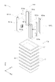
- the transport device 1 has a grip portion 101 that grips the container C, a moving mechanism 11 that moves the grip portion 101 in the X and Y directions, and a grip portion 101. Is provided with an elevating mechanism 12 for elevating and lowering the vehicle along the Z direction.
- the moving mechanism 11 is arranged along the Y direction at a position separated from the X direction on the storage plane F, and is fixed to the storage plane F with a pair of fixed guide rails 11R and a pair of fixed guides.
- a Y-direction moving body 11Y that is supported by the rail 11R and moves the grip portion 101 along the Y direction
- an X-direction moving body that is supported by the Y-direction moving body 11Y and moves the grip portion 101 along the X direction. It is equipped with 11X.
- the Y-direction moving body 11Y is composed of movable rails extending along the X-direction.
- the movable rails include a pair of rail portions 11Ya arranged parallel to each other.
- Each of both ends of the Y-direction moving body 11Y in the X direction is movably supported with respect to the fixed guide rail 11R, and moves in the Y direction along the fixed guide rail 11R.
- the Y-direction moving body 11Y is driven by a Y-direction moving driving unit (not shown) configured by, for example, a motor or the like.
- the X-direction moving body 11X is composed of a carriage that travels along the movable rails constituting the Y-direction moving body 11Y.
- the X-direction moving body 11X moves along the X-direction by traveling along the Y-direction moving body 11Y extending along the X-direction.
- the X-direction moving body 11X is driven by an X-direction moving drive unit (not shown) configured by, for example, a motor or the like.
- the grip portion 101 is supported by the X-direction moving body 11X. Therefore, when the X-direction moving body 11X moves along the X direction, the grip portion 101 supported by the X-direction moving body 11X also moves along the X direction. Further, as described above, the X-direction moving body 11X is supported by the Y-direction moving body 11Y. Therefore, when the Y-direction moving body 11Y moves along the Y direction, the grip portion 101 supported by the X-direction moving body 11X also moves along the Y direction. In this way, the grip portion 101 is configured to be movable along the X direction and the Y direction.
- the elevating mechanism 12 is configured to elevate the grip portion 101 along the Z direction, and in this example, it is supported by the X-direction moving body 11X.
- the elevating mechanism 12 includes a belt connected to the grip portion 101, and an elevating drive unit (not shown) which is composed of, for example, a motor or the like and drives the belt. By driving the belt by the elevating drive unit, the grip portion 101 moves up and down in the Z direction. As described above, in the present embodiment, the grip portion 101 is supported by the X-direction moving body 11X via the elevating mechanism 12.
- the transport device 1 includes a gripping mechanism 10.
- the gripping mechanism 10 includes the above-mentioned gripping portion 101, and a gripping drive unit (not shown) that is composed of, for example, a motor or the like and drives the gripping portion 101.
- the grip portion 101 is driven by the grip drive unit and is configured to change its state between a gripped state for gripping the container C and a non-grasping state for not gripping the container C.
- the grip portion 101 includes a pair of grip units 101U that approach or separate from each other in the X direction.
- Each of the pair of gripping units 101U is supported by the X-direction moving body 11X via the elevating mechanism 12 so as to move up and down synchronously between the pair of rail portions 11Y of the Y-direction moving body 11Y.
- Each of the pair of gripping units 101U is arranged side by side in the Y direction and is arranged between the pair of positioning tools 101a that approach or separate from each other in the Y direction and the pair of positioning tools 101a arranged in the Y direction. It is equipped with 101b.
- the positioning tool 101a is configured to contact the outer edge of the container C from the outside in the gripped state of the grip portion 101 to position the container C.
- the pair of positioning tools 101a provided in each of the pair of gripping units 101U that is, the four positioning tools 101a in total are in contact with the four corners of the container C having a rectangular planar shape. It is configured.
- the plurality of positioning tools 101a are configured as an L-shaped columnar body having an L-shaped cross section along the horizontal plane so as to match the outer edge shapes of the four corners of the container C.
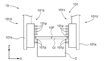
- the gripping tool 101b is configured to grip the flange-shaped gripped portion Cr that projects over the entire circumference at the outer edge of the upper end portion of the container C.
- the gripping tool 101b includes a plurality of protrusions 101p that engage with the gripped portion Cr of the container C and a support member 101s that supports the plurality of protrusions 101p in the gripped state of the gripping portion 101. ing.
- the support member 101s is formed in a columnar shape extending along the Z direction, and supports a plurality of protrusions 101p in the lower end region thereof.
- the plurality of projecting bodies 101p supported by the support member 101s are arranged side by side in the Z direction in the lower end region of the support member 101s, and are arranged on the side of the other support member 101s facing each other in the X direction. It protrudes toward the inside).
- a plurality of projecting bodies 101p arranged in the Z direction are arranged side by side in a plurality of rows (two rows in the example shown in FIG. 2) in the Y direction.
- Each of the plurality of projecting bodies 101p is urged by a spring in the direction of projecting inward (to the side of the other support member 101s). Therefore, as shown in FIG. 4, in the gripped state of the gripped portion 101, a part of the plurality of projecting bodies 101p receives a reaction force from the gripped portion Cr of the container C, thereby being outside against the force of the spring.
- the other part of the projecting body 101p which is retracted into the container C and is arranged below the part of the projecting body 101p, is in a state of supporting the gripped portion Cr of the container C from below. Further, in this state, the positioning tool 101a contacts or approaches the outer edge of the container C from the outside to position the container C in the X direction and the Y direction (see FIG. 3).
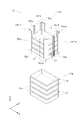
- the transport device 1 is configured to be able to move the container C alone or a plurality of containers C constituting the container group Cg at one time. Specifically, in the transport device 1, in a state where the gripping portion 101 grips one container C to be gripped, only the gripped container C is added to the gripped container C, or a step is placed on the grasped container C. It is configured to move a plurality of stacked containers C.
- FIGS. 2 and 3 show an example in which the transport device 1 takes out the upper three containers C from the container group Cg composed of the seven containers C and moves them.
- the transport device 1 can separate and move a single or a plurality of containers C from the container group Cg, and move another single or a plurality of containers C above the container group Cg. It can be placed and stacked.
- the containers C can be stacked over a plurality of stages to be in a stacked state.
- the container C is formed in a rectangular shape in a plan view, but the container C is not limited to this, and the container C has a polygonal shape or a circular shape other than the rectangular shape in a plan view. Alternatively, it may be formed in an elliptical shape.
- FIG. 1 it is possible to store a plurality of types of containers C having different bottom dimensions and heights on the storage plane F. In this example, as shown in FIG.
- each of the container groups Cg in which a plurality of containers C are stacked is composed of the same type of containers C having the same bottom surface dimensions and height.
- the container group Cg may be composed of a plurality of different types of containers C as long as they can be stacked.
- a container C is, for example, a plastic container for accommodating an container such as a part used in a production line of a factory.
- the container C in which such an inclusion is contained or the empty container C in which the inclusion is not contained is stored as a target article.
- the plane storage facility 100 includes a loading / unloading device 3 for transporting a container C (container group Cg) between the storage plane F and the outside of the storage plane F.
- the outside of the storage plane F is, for example, the production line of the factory described above.
- the carry-in / out device 3 has a carry-in conveyor 31 for carrying the container C from the outside of the storage plane F to the storage plane F and a carry-out conveyor for carrying out the container C from the storage plane F to the outside of the storage plane F. 32 and.
- the transport device 1 is configured to deliver the container C to and from the carry-in / out device 3, here, to each of the carry-in conveyor 31 and the carry-out conveyor 32.
- the loading / unloading device 3 is not limited to the above configuration, and may be configured by one conveyor. Further, the loading / unloading device 3 may be configured by a device other than the conveyor, such as a transport trolley.
- the outer edge portion E of the storage plane F is an area in which the container C is not placed.
- the area surrounded by the outer edge portion E on the storage plane F is a storage area AF on which the container C can be placed. That is, the storage plane F includes an area (outer edge portion E) on which the container C is not placed, and a storage area AF on which the container C can be placed.
- the outer edge E is open to workers.
- the storage plane F is formed in a rectangular shape, and the outer edge portion E is formed over four sides of the rectangular storage plane F.
- the outer edge portion E includes a first outer edge portion E1, a second outer edge portion E2, a third outer edge portion E3, and a fourth outer edge portion E4 constituting each side of the storage plane F.
- the first outer edge portion E1 and the second outer edge portion E2 are arranged to face each other, and the third outer edge portion E3 and the fourth outer edge portion E4 are arranged to face each other.
- the entrance / exit G that the worker can enter / exit is provided on any one of the four sides forming the outer edge portion E. 8, 9, and 11 show an example in which the entrance / exit G is provided at the first outer edge portion E1.
- the operator enters the storage plane F from the entrance / exit G provided in the first outer edge portion E1, and includes the first outer edge portion E1, the second outer edge portion E2, the third outer edge portion E3, and the fourth outer edge portion E4. It is passable.
- the storage plane F is surrounded by a fence, and the doorway G that allows access to the storage plane F is provided with a door that is normally closed.
- FIG. 10 shows an example in which the entrance / exit G is provided at the fourth outer edge portion E4.
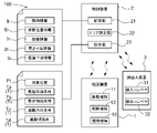
- control device 2 can communicate with the transfer device 1 and is configured to be able to control the transfer device 1.
- the control device 2 can also communicate with the carry-in / out device 3, and is configured to be able to control the carry-in / out device 3.
- the control device 2 manages the entire flat storage facility 100 in an integrated manner.
- the control device 2 has the position of the container group Cg placed on the storage plane F, the type of the container C constituting the container group Cg, and the number of containers C constituting the container group Cg (number of stacks). ) Is managed.
- the control device 2 includes, for example, a processor such as a microcomputer, peripheral circuits such as a memory, and the like. Then, each function is realized by the cooperation between these hardware and a program executed on a processor such as a computer.
- control device 2 includes a storage unit 21 for storing various information and an area setting unit 22 for setting the passage area AR (see FIG. 8 and the like) in the passage formation mode described later.
- the storage unit 21 stores the identification information Ii for identifying the container C and the storage position information Ip indicating the storage position of the container C in association with each other of all the containers C stored in the storage plane F. is doing. As a result, the control device 2 can grasp at which position in the storage plane F each of all the containers C stored in the storage plane F is stored.
- the storage unit 21 stores the number of stages information In indicating the number of layers of the container C in the container group Cg and the height dimension information Ih indicating the height dimension of the container C in association with the storage position information Ip. is doing.
- the control device 2 can grasp the number of containers C constituting the container group Cg by the stage number information In.
- the control device 2 can grasp the height dimension of each of the plurality of containers C constituting the container group Cg by the height dimension information Ih. Therefore, the control device 2 can grasp the height of the container group Cg formed by stacking a plurality of containers C in association with the position where the container group Cg is stored.
- the upper limit height of the container group Cg on the storage plane F is determined so that the operating transport device 1 and the container group Cg do not interfere with each other in relation to the installation position of the transport device 1. ..
- the upper limit height of the container group Cg is set so that the container group Cg stored on the storage plane F can be stably placed.
- the control device 2 manages the number of containers C constituting the container group Cg so as not to exceed the above upper limit height.
- the storage unit 21 stores the bottom dimension information Is indicating the bottom dimension of the container C in association with the storage position information Ip.
- the control device 2 can grasp the occupied area of the container C (container group Cg) placed on the storage plane F in the storage plane F and its position.
- the control device 2 is configured to be able to execute a carry-in control for carrying the container group Cg from the outside of the storage plane F to the storage plane F and a carry-out control for carrying out the container group Cg from the storage plane F to the outside of the storage plane F. ing.
- the control device 2 executes the carry-in control or the carry-out control by controlling the transport device 1 and the carry-in / carry-out device 3.
- the container group Cg carried in from the outside of the storage plane F by the carry-in conveyor 31 is carried into the storage plane F by the transport device 1 and placed directly on the storage plane F, or , Placed on another container group Cg already placed on the storage plane F. Then, the control device 2 stores the storage position information Ip for the carried-in container group Cg in the storage unit 21.
- the container group Cg is taken out from the storage plane F by the transport device 1, placed on the carry-out conveyor 32, and carried out to the outside of the storage plane F by the carry-out conveyor 32. Then, the control device 2 causes the storage unit 21 to delete the storage position information Ip for the carried-out container group Cg.
- the container group Cg carried out to the outside of the storage plane F is transported to various places such as a production line of a factory.
- control device 2 is configured to be able to execute a passage forming mode for forming a passage R through which an operator can pass in the storage plane F.
- the control device 2 accepts the designation of the target position Pt (see FIG. 8 and the like) in the storage plane F, and when the target position Pt is designated, the target position is from the outer edge portion E of the storage plane F.
- a passage R that connects to Pt and is passable by an operator is formed.
- the target position Pt is an arbitrary position on the storage plane F, and is designated by an operator, for example.
- the control device 2 sets the passage area AR for securing the passage R in the passage formation mode, and all the passage areas AR placed in the passage area AR by the transfer device 1.
- the container C (container group Cg) is moved to a place other than the aisle area AR in the storage plane F.
- the area setting unit 22 described above sets the passage area AR.
- the container C alone placed on the storage plane F is grasped by the control device 2 as a "container group Cg" having a stacking number of "1". Therefore, in the following, the container C alone may be referred to as a container group Cg.
- the passage area AR is a virtual area connecting the target position Pt and the outer edge portion E, and is set regardless of whether or not the container C is actually placed. After the execution of the passage formation mode, the container C does not exist in the passage area AR, and the passage R through which the operator can pass is formed in the area corresponding to the passage area AR.
- the transport device 1 places all the containers C placed in the passage area AR, and the container C (container group Cg) placed in a place other than the passage area AR. It is moved to a non-vacant area S, or moved onto a container group Cg placed in a place other than the passage area AR.
- the control device 2 updates the storage position information Ip stored in the storage unit 21 for the container C moved by executing the passage formation mode. For example, when the passage R from the target position Pt to the outer edge E is manually formed by an operator, the type of the container C moved for forming the passage R and the position of the container C before the movement are selected. , It is difficult to grasp by the control device 2. In order for the control device 2 to grasp such information, it is necessary for the operator to perform the work of storing the moved container C in the storage unit 21 again, such as by inputting the storage position information Ip. rice field.
- the control device 2 updates the storage position information Ip of the container C moved by executing the passage formation mode, so that the type and position of the container C after the movement can be easily grasped. Is possible. Therefore, it is not necessary to return the container C moved by executing the passage formation mode to the position before the movement, and the operation can be continued as it is.
- control device 2 accepts the designation of the setting condition T when executing the passage forming mode, and sets the passage area AR according to the designated setting condition T.
- the control device 2 accepts the designation of the setting condition T by the operator, and sets the passage area AR by the area setting unit 22 according to the designated setting condition T.
- the setting condition T includes the shortest distance condition Ta that minimizes the distance from the outer edge portion E to the target position Pt, and the minimum article condition that minimizes the number of containers C placed in the passage area AR.
- Tb the passage direction condition
- Tc that sets the extension direction of the passage area AR is included.
- the minimum article condition Tb is a condition for minimizing the number of container group Cg placed in the aisle area AR.
- the setting condition T includes the passage width condition Td for setting the size of the width of the passage area AR (passage width Rw: see FIG. 8 and the like).
- the passage width Rw of the passage area AR is a dimension in a direction orthogonal to the direction in which the passage area AR extends.
- the passage R having an appropriate passage width Rw can be formed by setting the size of the passage width Rw according to various situations.
- the situation considered here is, for example, the size of the device when it is necessary to make a device such as a dolly reach the target position Pt, or when a plurality of workers head toward the target position Pt. The number of people etc. is included.
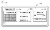
- the control device 2 includes an operation unit 23 that can be operated by an operator.
- the operation unit 23 accepts the designation of the target position Pt by the operation of the operator.
- the operation unit 23 receives the designation of the setting condition T by the operation of the operator in addition to the target position Pt. Further, the operation unit 23 also accepts the designation of the passage width condition Td by the operation of the operator.
- the operation unit 23 includes an operation screen 23S.
- the operation screen 23S is configured as a touch panel.
- the target position Pt can be set, and in this example, the target position setting image 23a on which the operator can input or select the target position Pt is displayed.
- the setting condition T can be set on the operation screen 23S, and in this example, the operator can input or select the setting condition T from the shortest distance condition Ta, the minimum article condition Tb, and the passage direction condition Tc.
- Setting condition setting image 23b is displayed.
- the passage width Rw of the passage area AR can be set, and in this example, the passage width setting image 23c in which the operator can input or select the passage width Rw is displayed.
- the passage width setting image 23c in which the operator can input or select the passage width Rw is displayed.
- an image target position setting image 23a, setting condition setting image 23b, passage
- the width setting image 23c) is displayed.
- the operation unit 23 may be configured to perform various inputs using a keyboard, a monitor, or the like.
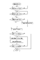
- the control device 2 determines whether or not the target position Pt is selected (step # 1). When the control device 2 determines that the target position Pt is selected (step # 1: Yes), the control device 2 determines whether or not the setting condition T is selected (step # 2). Then, when the control device 2 determines that the setting condition T is selected (step # 2: Yes), the control device 2 determines whether or not the passage width Rw is selected (step # 3).
- the control device 2 determines that the passage width Rw is not selected (step # 3: No)
- the control device 2 sets a default passage width Rw (step # 4), and sets the selected target positions Pt and settings, respectively.
- the passage area AR is set based on the condition T and the specified passage width Rw (step # 5).
- the control device 2 determines that the passage width Rw is selected (step # 3: Yes)
- the passage is based on the selected target position Pt, the setting condition T, and the passage width Rw, respectively.
- Set the area AR (step # 5).
- the default passage width Rw set in the step # 4 may be set to a width that allows the operator to pass through, and may be set in the range of, for example, 500 mm to 1500 mm.
- the control device 2 determines whether or not the container C is present in the passage area AR (step # 6). This determination is made based on the storage location information Ip.
- the control device 2 determines that the container C is present in the aisle area AR (step # 6: Yes)
- the control device 2 moves the container C to a place other than the aisle area AR in the storage plane F (step # 7).
- the control device 2 updates the storage position information Ip of the moved container C (step # 8).
- the control device 2 ends the passage formation mode.
- step # 9 when it is determined that the container C still exists in the passage area AR (step # 9: No), the control device 2 repeats the steps of step # 7 and step # 8.
- the control device 2 sets the passage area AR (step # 5), and if it is determined in step # 6 thereafter that there is no container C in the passage area AR (step # 6: No), the same as above. Ends the passage formation mode.
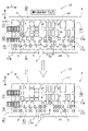
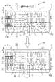
- FIG. 8 shows a case where the passage formation mode is executed under the shortest distance condition Ta.
- the control device 2 sets the passage area AR according to the shortest distance condition Ta.
- the control device 2 when the shortest distance condition Ta is specified as the setting condition T, the control device 2 is the target at the outer edge portion E based on the storage position information Ip of the container group Cg placed on the target position Pt. The position closest to the position Pt is calculated, and the passage area AR is set between the calculated position and the target position Pt. The area surrounded by the alternate long and short dash line in FIG. 8 is the passage area AR set so as to satisfy the shortest distance condition Ta. In the illustrated example, the passage area AR is set between the target position Pt and the first outer edge portion E1, and the container group Cg is placed at eight places in the passage area AR. The control device 2 moves the container group Cg placed at the eight locations to a location other than the aisle area AR on the storage plane F.
- the place to move the container group Cg is on the other container group Cg placed in a place other than the passage area AR in the storage plane F, or in the empty area S.
- the passage formation mode As shown in the lower figure of FIG. 8, all the containers C placed in the passage area AR are removed, and the passage R through which the operator can pass is entered in the area corresponding to the passage area AR. Is formed.
- the setting condition T By setting the setting condition T to the shortest distance condition Ta in this way, it is possible to form a passage R in which the operator reaches the target position Pt from the outer edge portion E in the shortest distance.
- the control device 2 sets the passage area AR so that when the shortest distance condition Ta is specified as the setting condition T, the side of the outer edge portion E where the entrance / exit G is provided becomes the starting point. .. Specifically, the control device 2 sets the passage area AR starting from the position closest to the target position Pt on the side (outer edge portion E) where the entrance / exit G is provided. As a result, the passage R can be formed from a position close to the doorway G.
- FIG. 8 shows an example in which the shortest distance condition Ta is specified as the setting condition T, and the passage area AR is set with the first outer edge portion E1 provided with the entrance / exit G as a starting point. In the example shown in FIG.
- the set passage area AR does not differ depending on the presence or absence of the condition that the side (first outer edge portion E1) provided with the entrance / exit G in the outer edge portion E is the starting point.
- a passage area AR different from the above may be set depending on which location is designated as the target position Pt. For example, for the second target position Pt2 shown in FIG. 8, when the passage area AR is set according to the shortest distance condition Ta without considering the side where the entrance / exit G is provided in the outer edge portion E, “AR2” is shown in FIG. The area shown by is set.
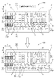
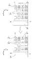
- FIG. 9 shows a case where the passage formation mode is executed under the minimum article condition Tb.
- the control device 2 when the minimum article condition Tb is specified as the setting condition T, the control device 2 has the target position Pt based on the storage position information Ip of all the container group Cg placed on the storage plane F.
- the passage area AR is set in the region where the number of the container group Cg placed between the container group E and the outer edge portion E is the minimum.
- the area surrounded by the alternate long and short dash line in FIG. 9 is the passage area AR set so as to satisfy the minimum article condition Tb.
- the passage area AR is set between the target position Pt and the second outer edge portion E2, and the container group Cg is placed at four places in the passage area AR.
- the control device 2 moves the container group Cg placed at the four locations to a location other than the aisle area AR on the storage plane F.
- all the containers C placed in the passage area AR are removed, and the passage R through which the worker can pass is formed in the area corresponding to the passage area AR. ..
- the setting condition T to the shortest distance condition Ta in this way, the number of movements of the container group Cg (or the container C alone) by the transfer device 1 can be suppressed to a small number, and the transfer device 1 forms the passage R. Time can be shortened.
- the passage area AR is set according to the minimum article condition Tb without considering the side where the entrance / exit G is provided in the outer edge portion E.
- the minimum article condition Tb is specified as the setting condition T
- the passage area AR may be set so that the side of the outer edge portion E where the entrance / exit G is provided becomes the starting point.
- “AR2” is shown in FIG. 9 so that the number of container group Cg existing up to the target position Pt is minimized from the first outer edge portion E1 provided with the entrance / exit G as a starting point. Area is set.
- the control device 2 controls the shortest distance condition Ta. It is preferable to set the candidate having the smallest number of container group Cg included in each candidate among the candidates of two or more passage area ARs satisfying the condition in the passage area AR. As a result, among the candidates for the passage R having the shortest distance from the outer edge portion E to the target position Pt, the candidate having the shortest formation time of the passage R by the transport device 1 can be formed as the passage R.
- the control device 2 sets the minimum article condition Tb. It is preferable to set the candidate having the shortest distance from the outer edge portion E to the target position Pt as the passage area AR among the candidates of the two or more passage areas AR satisfying the above conditions. Thereby, among the candidates having the shortest formation time of the passage R by the transport device 1, the candidate having the shortest distance from the outer edge portion E to the target position Pt can be formed as the passage R.
- passage area ARs Even if the above conditions are set, if a plurality of passage area ARs can be set, other conditions may be added, or the plurality of passage areas AR may be added.
- the passage area AR selected by the operator may be set.
- FIG. 10 shows a case where the passage formation mode is executed under the passage direction condition Tc.
- the control device 2 sets the passage area AR from the target position Pt along the direction specified by the passage direction condition Tc.
- the passage R is formed along the directions according to various situations, for example, in consideration of the current position of the worker and the position of the entrance / exit G to the storage plane F. can.
- a direction along the Y direction is designated as the passage direction condition Tc.
- the entrance / exit G is provided at the fourth outer edge portion E4.
- the area surrounded by the alternate long and short dash line in FIG. 10 is the passage area AR set so as to satisfy this passage direction condition Tc.
- the passage area AR is set so as to extend from the target position Pt in the Y direction and reach the fourth outer edge portion E4, and the container group Cg is placed at five places in the passage area AR.
- the control device 2 moves the container group Cg placed at the five locations to a location other than the aisle area AR on the storage plane F.
- the place to move the container group Cg is on the other container group Cg placed in a place other than the passage area AR in the storage plane F, or in the empty area S.
- FIG. 11 shows another example in the case where the setting condition T is the passage direction condition Tc.
- the doorway G is provided at the first outer edge portion E1.
- the passage direction condition Tc includes the condition of the direction extending from the target position Pt and the distance thereof.
- the control device 2 sets the passage area AR according to the extending direction from the target position Pt and the distance thereof included in the passage direction condition Tc.
- the area surrounded by the alternate long and short dash line in FIG. 11 is the passage area AR set so as to satisfy the passage direction condition Tc.
- the extending direction from the target position Pt is designated in the Y direction
- the distance is designated as the first extending distance Ly
- the extending direction from the target position Pt is designated in the X direction.
- An example is shown in which the distance is specified as the second extended distance Lx and the passage area AR is set.
- the container group Cg is placed at five locations in the passage area AR.
- the control device 2 moves the container group Cg placed at the five locations to a location other than the aisle area AR on the storage plane F.
- all the containers C placed in the passage area AR are removed, and the passage R through which the worker can pass is formed in the area corresponding to the passage area AR. ..
- the passage R is formed so as to connect the position closest to the entrance / exit G in the first outer edge portion E1 (outer edge portion E) and the target position Pt. is doing.
- the empty area S for moving the container C placed in the aisle area AR may be insufficient. be.
- the control device 2 is in the storage plane F for moving all the containers C placed in the passage area AR when the passage formation mode is executed.
- the transport device 1 increases the number of stacks of the containers C stored in the storage plane F to increase the storage capacity in the storage plane F.
- a process of securing a place (vacant area S) for moving all the containers C placed in the passage area AR (vacant area securing process) is executed.
- the control device 2 in the vacant area securing process, is placed in a place other than the aisle area AR on the storage plane F within a range that is equal to or less than the upper limit stacking number, which is the upper limit of the stacking number of the containers C set in advance.
- the number of stacked containers C to be placed is increased to secure an empty area S.
- FIG. 12 illustrates a case where the upper limit stacking number on the storage plane F is “10”, and the numbers shown inside the container group Cg in the figure are the current containers C in each container group Cg. Shows the number of stacks.
- the positions where each of the plurality of container groups Cg are stored are shown as the first to ninth storage positions (P1 to P9).
- the control device 2 executes the free area securing process, and is a plurality of container group Cg having a stacking number equal to or less than the upper limit stacking number around the passage area AR, and can be stacked with each other.
- the transport device 1 is controlled so as to reduce the number of container group Cg by combining a plurality of container group Cg with each other to form a new container group Cg having a stacking number equal to or less than the upper limit stacking number. Note that FIG.
- FIG. 12 illustrates a case where all the container groups Cg are composed of containers C having the same size and can be stacked on top of each other.
- container groups Cg composed of containers C having different sizes that cannot be stacked with each other are mixed, the above control is performed only with the container groups Cg that can be stacked.
- the container group Cg (number of stacks: 3) placed in the second storage position P2 is combined with the container group Cg (number of stacks: 2) placed in the third storage position P3.
- the number of stacks A new container group Cg of "10" is formed at the second storage position P2.
- an empty area S in which the container C is not placed is formed in each of the third storage position P3, the sixth storage position P6, and the seventh storage position P7.
- the stage A new container group Cg having a stacking number of "10" is formed at the fourth storage position P4.
- an empty area S in which the container C is not placed is formed in the eighth storage position P8.
- the control device 2 controls the transfer device 1 so as to move the container C placed in the passage area AR to the plurality of empty areas S formed as described above.
- the minimum article condition Tb is a condition for minimizing the number of container group Cg placed in the passage area AR.
- the minimum article condition Tb may be a condition that minimizes the number of containers C placed in the aisle area AR. That is, in this case, the control device 2 takes into consideration the number of container group Cg placed in the passage area AR and the number of stacks thereof, so that the number of containers C in the passage area AR is minimized. Set the area AR.
- the storage plane F is formed in a rectangular shape and the outer edge portion E is formed over four sides of the rectangular storage plane F has been described.
- the shape of the storage plane F is not limited to such an example, and various shapes such as a polygonal shape, a circular shape, and an elliptical shape can be adopted.
- the outer edge portion E that the operator can pass through is not essential, and the entire storage plane F may be the storage area AF.
- the entrance / exit G is provided in the first outer edge portion E1 .
- the entrance / exit G is provided at the second outer edge portion E2, the third outer edge portion E3, or the fourth outer edge portion E4. It may be provided. Further, the number of entrances / exits G may be singular or plural.
- control device 2 accepts the designation of the setting condition T and sets the passage area AR according to the designated setting condition T when the passage forming mode is executed.
- the control device 2 may automatically set the passage area AR without accepting the setting condition T.
- the control device 2 sets the passage area AR according to a predetermined condition.
- the predetermined conditions may be any of the above-mentioned shortest distance condition Ta, minimum article condition Tb, and passage direction condition Tc, or may be different from these conditions.
- the target article is a container C in which a plurality of stackable articles can be stacked.
- the target article may be a container C that cannot be stacked, or may be various articles other than the container C.
- the moving mechanism 11 comprises a Y-direction moving body 11Y formed in a rail shape and an X-direction moving body 11X composed of a trolley traveling along the Y-direction moving body 11Y.
- the moving mechanism 11 may be configured so that the gripping portion 101 for gripping the container C can be moved in both the X direction and the Y direction.
- the moving mechanism 11 may be configured by a robot arm or the like capable of moving the grip portion 101 in the X direction, the Y direction, and the Z direction.
- the flat storage equipment related to this disclosure is A storage plane on which multiple target items are placed and stored, A transport device for moving the target article in the storage plane, and A control device for controlling the operation of the transfer device is provided.
- the control device accepts the designation of the target position in the storage plane, and when the target position is designated, forms a passage through which an operator can pass from the outer edge portion of the storage plane to the target position. It is possible to execute the passage formation mode to The control device sets a passage area for securing the passage in the passage formation mode, and the transfer device causes all the target articles placed in the passage area to be placed in the storage plane. Move to a place other than the aisle area.
- the passage forming mode for forming the passage connecting the outer edge portion of the storage plane to the target position is executed. As a result, it is possible to form a passage for the operator to enter to an arbitrary target position by using the transport device.
- the position where the load collapse occurred is targeted.
- a passage to this target position can be formed on a storage plane.
- the control device For each of the target articles stored in the storage plane, the control device associates the identification information for identifying the target article with the storage position information indicating the position where the target article is stored. Equipped with a storage unit to memorize It is preferable that the control device updates the storage position information for the target article moved by executing the passage formation mode.
- control device accepts the designation of the setting condition and sets the passage area according to the designated setting condition when the passage forming mode is executed.
- a passage can be formed in the passage area set according to the setting conditions.
- the control device sets the passage area according to the designated setting conditions.
- the above setting conditions include The shortest distance condition that minimizes the distance from the outer edge portion to the target position, the minimum article condition that minimizes the number of the target articles placed in the passage area, and the extension direction of the passage area are set. It is preferable that any of the passage direction conditions to be performed is included.
- the passage area can be set by selecting an appropriate setting condition according to the situation at that time. For example, by setting the setting condition to the shortest distance condition, it is possible to form a passage in which the operator can reach the target position from the outer edge portion in the shortest distance. Further, by setting the setting condition to the minimum article condition, the number of moving the target articles by the transport device can be suppressed to a small number, and the time for the transport device to form the passage can be shortened. Further, by setting the setting condition as the passage direction condition, the passage can be formed along the direction according to various situations in consideration of the situation such as the current position of the worker and the position of the entrance / exit to the storage plane.
- the installation condition includes any one of the shortest distance condition, the minimum article condition, and the passage direction condition.
- the storage plane is formed in a rectangular shape.
- the outer edge is formed over four sides of the rectangular storage plane.
- An entrance / exit that the worker can enter / exit is provided on any one of the four sides forming the outer edge portion.
- the control device sets the passage area so that the side provided with the entrance / exit at the outer edge portion becomes the starting point. It is suitable to set.
- the passage when either the shortest distance condition or the minimum article condition is specified as the setting condition, the passage can be formed from a position close to the doorway.
- the setting condition includes a passage width condition for setting the size of the width of the passage area.
- the width of the passage can be set according to various situations.
- the situation considered here is, for example, the size of the device when it is necessary to reach the target position of a device such as a dolly, or the number of people when a plurality of workers head toward the target position. Etc. are included.
- the target article is a container in which a plurality of stacks can be stacked.
- the control device may lack a place in the storage plane for moving all the target articles placed in the aisle area.
- the storage capacity in the storage plane is increased, and all the target articles placed in the aisle area are removed. It is preferable to execute a process of securing a place for moving.
- the directions along the storage plane and orthogonal to each other are the X direction and the Y direction, and the direction orthogonal to the storage plane is the Z direction.
- the transport device includes a grip portion that grips the target article, a moving mechanism that moves the grip portion in the X direction and the Y direction, and an elevating mechanism that raises and lowers the grip portion along the Z direction. It is preferable to have it.
- the target article can be appropriately moved to each position in the storage plane.
- the technique according to the present disclosure includes a storage plane on which a plurality of target articles are placed and stored, a transport device for moving the target article within the storage plane, and a control device for controlling the operation of the transport device. It can be used for the provided flat storage equipment.
Landscapes
- Engineering & Computer Science (AREA)
- Mechanical Engineering (AREA)
- Warehouses Or Storage Devices (AREA)
- Control Of Conveyors (AREA)
Abstract
Description
複数の対象物品を載置して保管する保管平面と、
前記対象物品を前記保管平面内で移動させる搬送装置と、
前記搬送装置の動作を制御する制御装置と、を備え、
前記制御装置は、前記保管平面内における対象位置の指定を受け付け、前記対象位置が指定された場合に、前記保管平面の外縁部から前記対象位置までを繋ぐ、作業者が通行可能な通路を形成する通路形成モードを実行可能であり、
前記制御装置は、前記通路形成モードにおいて、前記通路を確保するための通路エリアを設定し、前記搬送装置によって、前記通路エリア内に載置された全ての前記対象物品を前記保管平面内における前記通路エリア以外の場所へ移動させる。
図1に示すように、平面保管設備100は、複数の容器Cを載置して保管する保管平面Fと、容器Cを保管平面F内で移動させる搬送装置1と、搬送装置1の動作を制御する制御装置2(図5参照)と、を備えている。本実施形態では、平面保管設備100は、保管平面Fに、容器C単体、又は複数の容器Cを段積み状態としてなる容器群Cgを載置して保管するように構成されている。平面保管設備100では、部品等の収容物が収容された容器C、或いは収容物が収容されていない空の容器Cを、対象物品として保管する。すなわち本実施形態では、対象物品が、複数を段積み可能な容器Cであり、容器Cが「対象物品」に相当する。
外縁部Eは、作業者が通行可能となっている。
図示の例では、第1外縁部E1と第2外縁部E2とが対向して配置され、第3外縁部E3と第4外縁部E4とが対向して配置されている。
図5に示すように、制御装置2は、搬送装置1との間で通信可能であり、搬送装置1を制御可能に構成されている。本例では、制御装置2は、搬出入装置3との間でも通信可能であり、搬出入装置3を制御可能に構成されている。また、制御装置2は、平面保管設備100の全体を統括して管理する。本実施形態では、制御装置2は、保管平面Fに載置された容器群Cgの位置、容器群Cgを構成する容器Cの種類、及び容器群Cgを構成する容器Cの数(段積み数)を管理している。なお、本実施形態では、制御装置2は、容器Cが単体で保管平面Fに載置されている場合にも、容器群Cgを構成する容器Cの数(段積み数)が「1」である容器群Cgとして管理することとしている。制御装置2は、例えば、マイクロコンピュータ等のプロセッサ、メモリ等の周辺回路等を備えている。そして、これらのハードウェアとコンピュータ等のプロセッサ上で実行されるプログラムとの協働により、各機能が実現される。
次に、平面保管設備のその他の実施形態について説明する。
以下、上記において説明した平面保管設備について説明する。
複数の対象物品を載置して保管する保管平面と、
前記対象物品を前記保管平面内で移動させる搬送装置と、
前記搬送装置の動作を制御する制御装置と、を備え、
前記制御装置は、前記保管平面内における対象位置の指定を受け付け、前記対象位置が指定された場合に、前記保管平面の外縁部から前記対象位置までを繋ぐ、作業者が通行可能な通路を形成する通路形成モードを実行可能であり、
前記制御装置は、前記通路形成モードにおいて、前記通路を確保するための通路エリアを設定し、前記搬送装置によって、前記通路エリア内に載置された全ての前記対象物品を前記保管平面内における前記通路エリア以外の場所へ移動させる。
前記制御装置は、前記保管平面に保管されている全ての前記対象物品のそれぞれについて、前記対象物品を識別するための識別情報と前記対象物品が保管された位置を示す保管位置情報とを関連付けて記憶する記憶部を備え、
前記制御装置は、前記通路形成モードの実行により移動させた前記対象物品について、前記保管位置情報を更新する、と好適である。
前記制御装置は、前記通路形成モードを実行する場合に、設定条件の指定を受け付け、指定された前記設定条件に従って前記通路エリアを設定する、と好適である。
前記設定条件には、
前記外縁部から前記対象位置までの距離を最短にする最短距離条件、前記通路エリア内に載置された前記対象物品の数を最少にする最少物品条件、及び前記通路エリアの延在方向を設定する通路方向条件、の何れかが含まれる、と好適である。
前記保管平面が矩形状に形成され、
前記外縁部が矩形状の前記保管平面の4つの辺に亘って形成され、
前記作業者が出入り可能な出入口が、前記外縁部を形成する4つの辺のうち何れかの辺に設けられ、
前記制御装置は、前記設定条件として前記最短距離条件及び前記最少物品条件のいずれかが指定された場合に、前記外縁部における前記出入口が設けられた辺が出発点となるように前記通路エリアを設定する、と好適である。
前記設定条件には、前記通路エリアの幅の大きさを設定する通路幅条件が含まれる、と好適である。
前記対象物品が、複数を段積み可能な容器であり、
前記制御装置は、前記通路形成モードを実行する場合において、前記通路エリア内に載置された全ての前記対象物品を移動させるための前記保管平面内の場所が不足している場合には、前記搬送装置によって、前記保管平面に保管されている前記対象物品の段積み数を増加させることで前記保管平面内の保管容量を増大させ、前記通路エリア内に載置された全ての前記対象物品を移動させるための場所を確保する処理を実行する、と好適である。
前記保管平面に沿う方向であって互いに直交する方向をX方向及びY方向とし、前記保管平面に直交する方向をZ方向として、
前記搬送装置は、前記対象物品を把持する把持部と、前記把持部を前記X方向及び前記Y方向に移動させる移動機構と、前記把持部を前記Z方向に沿って昇降させる昇降機構と、を備えていると好適である。
1 :搬送装置
11 :移動機構
101 :把持部
12 :昇降機構
2 :制御装置
21 :記憶部
AR :通路エリア
R :通路
Rw :通路幅
F :保管平面
E :外縁部
G :出入口
S :空き領域
C :容器(対象物品)
Pt :対象位置
Ii :識別情報
Ip :保管位置情報
T :設定条件
Ta :最短距離条件
Tb :最少物品条件
Tc :通路方向条件
Td :通路幅条件
Claims (8)
- 複数の対象物品を載置して保管する保管平面と、
前記対象物品を前記保管平面内で移動させる搬送装置と、
前記搬送装置の動作を制御する制御装置と、を備え、
前記制御装置は、前記保管平面内における対象位置の指定を受け付け、前記対象位置が指定された場合に、前記保管平面の外縁部から前記対象位置までを繋ぐ、作業者が通行可能な通路を形成する通路形成モードを実行可能であり、
前記制御装置は、前記通路形成モードにおいて、前記通路を確保するための通路エリアを設定し、前記搬送装置によって、前記通路エリア内に載置された全ての前記対象物品を前記保管平面内における前記通路エリア以外の場所へ移動させる、平面保管設備。 - 前記制御装置は、前記保管平面に保管されている全ての前記対象物品のそれぞれについて、前記対象物品を識別するための識別情報と前記対象物品が保管された位置を示す保管位置情報とを関連付けて記憶する記憶部を備え、
前記制御装置は、前記通路形成モードの実行により移動させた前記対象物品について、前記保管位置情報を更新する、請求項1に記載の平面保管設備。 - 前記制御装置は、前記通路形成モードを実行する場合に、設定条件の指定を受け付け、指定された前記設定条件に従って前記通路エリアを設定する、請求項1又は2に記載の平面保管設備。
- 前記設定条件には、
前記外縁部から前記対象位置までの距離を最短にする最短距離条件、前記通路エリア内に載置された前記対象物品の数を最少にする最少物品条件、及び前記通路エリアの延在方向を設定する通路方向条件、の何れかが含まれる、請求項3に記載の平面保管設備。 - 前記保管平面が矩形状に形成され、
前記外縁部が矩形状の前記保管平面の4つの辺に亘って形成され、
前記作業者が出入り可能な出入口が、前記外縁部を形成する4つの辺のうち何れかの辺に設けられ、
前記制御装置は、前記設定条件として前記最短距離条件及び前記最少物品条件のいずれかが指定された場合に、前記外縁部における前記出入口が設けられた辺が出発点となるように前記通路エリアを設定する、請求項4に記載の平面保管設備。 - 前記設定条件には、前記通路エリアの幅の大きさを設定する通路幅条件が含まれる、請求項3から5のいずれか一項に記載の平面保管設備。
- 前記対象物品が、複数を段積み可能な容器であり、
前記制御装置は、前記通路形成モードを実行する場合において、前記通路エリア内に載置された全ての前記対象物品を移動させるための前記保管平面内の場所が不足している場合には、前記搬送装置によって、前記保管平面に保管されている前記対象物品の段積み数を増加させることで前記保管平面内の保管容量を増大させ、前記通路エリア内に載置された全ての前記対象物品を移動させるための場所を確保する処理を実行する、請求項1から6のいずれか一項に記載の平面保管設備。 - 前記保管平面に沿う方向であって互いに直交する方向をX方向及びY方向とし、前記保管平面に直交する方向をZ方向として、
前記搬送装置は、前記対象物品を把持する把持部と、前記把持部を前記X方向及び前記Y方向に移動させる移動機構と、前記把持部を前記Z方向に沿って昇降させる昇降機構と、を備えている、請求項1から7のいずれか一項に記載の平面保管設備。
Priority Applications (2)
| Application Number | Priority Date | Filing Date | Title |
|---|---|---|---|
| CN202180083172.8A CN116802131B (zh) | 2020-12-09 | 2021-11-30 | 平面保管设备 |
| US18/266,078 US12312169B2 (en) | 2020-12-09 | 2021-11-30 | Plane storage facility |
Applications Claiming Priority (2)
| Application Number | Priority Date | Filing Date | Title |
|---|---|---|---|
| JP2020-204151 | 2020-12-09 | ||
| JP2020204151A JP7435427B2 (ja) | 2020-12-09 | 2020-12-09 | 平面保管設備 |
Publications (1)
| Publication Number | Publication Date |
|---|---|
| WO2022124141A1 true WO2022124141A1 (ja) | 2022-06-16 |
Family
ID=81973217
Family Applications (1)
| Application Number | Title | Priority Date | Filing Date |
|---|---|---|---|
| PCT/JP2021/043874 Ceased WO2022124141A1 (ja) | 2020-12-09 | 2021-11-30 | 平面保管設備(plane storage facility) |
Country Status (5)
| Country | Link |
|---|---|
| US (1) | US12312169B2 (ja) |
| JP (1) | JP7435427B2 (ja) |
| CN (1) | CN116802131B (ja) |
| TW (1) | TWI904293B (ja) |
| WO (1) | WO2022124141A1 (ja) |
Cited By (1)
| Publication number | Priority date | Publication date | Assignee | Title |
|---|---|---|---|---|
| EP4501814A1 (en) * | 2023-08-03 | 2025-02-05 | Daifuku Co., Ltd. | Container transport facility |
Citations (3)
| Publication number | Priority date | Publication date | Assignee | Title |
|---|---|---|---|---|
| JPH02182607A (ja) * | 1988-09-30 | 1990-07-17 | Kongo Kk | 自動移動棚装置 |
| JPH06135516A (ja) * | 1991-08-20 | 1994-05-17 | Kongo Kk | 移動棚装置 |
| JP2018043804A (ja) * | 2016-09-12 | 2018-03-22 | 株式会社ダイフク | 平置き保管設備 |
Family Cites Families (12)
| Publication number | Priority date | Publication date | Assignee | Title |
|---|---|---|---|---|
| US2165513A (en) * | 1938-07-28 | 1939-07-11 | Roy W Smith | Cold storage locker room |
| JPS6135516A (ja) | 1984-07-27 | 1986-02-20 | Hitachi Ltd | 半導体の熱処理制御方法 |
| JPH0257607A (ja) | 1988-08-20 | 1990-02-27 | Kawasaki Steel Corp | 射出成形用粉末および金属焼結体の製造方法 |
| US5007785A (en) * | 1988-11-14 | 1991-04-16 | Staalkat B.V. | Method and apparatus for unloading stacks of trays |
| US6694767B2 (en) * | 2002-06-19 | 2004-02-24 | Jouan | Work enclosure having article supports that obstruct access openings |
| EP3598140B1 (en) * | 2009-10-19 | 2024-04-03 | Brooks Automation Inc. | Modular sample store and method for storing and providing samples |
| US9238558B2 (en) * | 2012-09-12 | 2016-01-19 | Graphic Packaging International, Inc. | Reciprocating placer system |
| ES2986337T3 (es) * | 2015-04-15 | 2024-11-11 | Ocado Innovation Ltd | Sistema de manejo de objetos |
| JP6268610B2 (ja) * | 2015-04-30 | 2018-01-31 | 株式会社ダイフク | 平面保管設備 |
| US10259648B2 (en) * | 2017-04-06 | 2019-04-16 | Lineage Logistics, LLC | Automated warehouse improvements |
| JP6827905B2 (ja) * | 2017-10-26 | 2021-02-10 | 株式会社日立物流 | 棚管理システム及び棚管理方法 |
| CN110182528B (zh) * | 2019-04-11 | 2020-12-18 | 上海快仓智能科技有限公司 | 用于货架阵列的出入库控制方法和搬运系统 |
-
2020
- 2020-12-09 JP JP2020204151A patent/JP7435427B2/ja active Active
-
2021
- 2021-11-30 US US18/266,078 patent/US12312169B2/en active Active
- 2021-11-30 WO PCT/JP2021/043874 patent/WO2022124141A1/ja not_active Ceased
- 2021-11-30 CN CN202180083172.8A patent/CN116802131B/zh active Active
- 2021-12-03 TW TW110145330A patent/TWI904293B/zh active
Patent Citations (3)
| Publication number | Priority date | Publication date | Assignee | Title |
|---|---|---|---|---|
| JPH02182607A (ja) * | 1988-09-30 | 1990-07-17 | Kongo Kk | 自動移動棚装置 |
| JPH06135516A (ja) * | 1991-08-20 | 1994-05-17 | Kongo Kk | 移動棚装置 |
| JP2018043804A (ja) * | 2016-09-12 | 2018-03-22 | 株式会社ダイフク | 平置き保管設備 |
Cited By (4)
| Publication number | Priority date | Publication date | Assignee | Title |
|---|---|---|---|---|
| EP4501814A1 (en) * | 2023-08-03 | 2025-02-05 | Daifuku Co., Ltd. | Container transport facility |
| JP2025022392A (ja) * | 2023-08-03 | 2025-02-14 | 株式会社ダイフク | 容器搬送設備 |
| JP7831438B2 (ja) | 2023-08-03 | 2026-03-17 | 株式会社ダイフク | 容器搬送設備 |
| US12595121B2 (en) | 2023-08-03 | 2026-04-07 | Daifuku Co., Ltd. | Container transport facility |
Also Published As
| Publication number | Publication date |
|---|---|
| US12312169B2 (en) | 2025-05-27 |
| JP7435427B2 (ja) | 2024-02-21 |
| US20240092571A1 (en) | 2024-03-21 |
| CN116802131B (zh) | 2026-01-02 |
| CN116802131A (zh) | 2023-09-22 |
| TW202229136A (zh) | 2022-08-01 |
| TWI904293B (zh) | 2025-11-11 |
| JP2022091356A (ja) | 2022-06-21 |
Similar Documents
| Publication | Publication Date | Title |
|---|---|---|
| CN114829272B (zh) | 拣选系统、包括拣选系统的存储系统以及拣选方法 | |
| JP6870517B2 (ja) | 搬送車及び搬送設備 | |
| JP2018052659A (ja) | 物品搬送設備 | |
| WO2022024507A1 (ja) | 物品収納設備(article storage facility) | |
| EP4204333B1 (en) | A method and system for picking products in a picking station of an automatic storage and retrieval system | |
| JP2022023338A (ja) | 物品収納設備 | |
| EP4172892A1 (en) | Multiposition search | |
| JP2023161240A (ja) | レーザー切断ピッキング及び製品パレット載置全自動システム | |
| EP3257791B1 (en) | Planar storage facility | |
| WO2022124141A1 (ja) | 平面保管設備(plane storage facility) | |
| JP2023524443A (ja) | 自動保管および回収システムに保管コンテナを移送することと、自動保管および回収システムから移送することとを行うための、同一のポートと相互作用するように割り当てられたコンテナ取扱車両の動作キャパシティの最適な活用 | |
| JP3369392B2 (ja) | 物品保管設備 | |
| JP7444138B2 (ja) | 物品収容設備 | |
| JP7409133B2 (ja) | ピッキング設備 | |
| WO2023155722A1 (zh) | 仓储系统及其控制方法 | |
| JP7831439B2 (ja) | 物品保管設備 | |
| JPH09235004A (ja) | 物品保管設備 | |
| JP7700918B1 (ja) | 物品搬送設備 | |
| JP2024100432A (ja) | 物品搬送設備 | |
| JP2018141292A (ja) | 機械式駐車設備 | |
| WO2024161695A1 (ja) | 自動倉庫システムの制御システム及び制御方法 | |
| CN113247518A (zh) | 拣选设备 | |
| JP2025022392A (ja) | 容器搬送設備 | |
| JP2003095411A (ja) | 物品保管装置 | |
| JP2022180083A (ja) | 物品仕分け設備 |
Legal Events
| Date | Code | Title | Description |
|---|---|---|---|
| 121 | Ep: the epo has been informed by wipo that ep was designated in this application |
Ref document number: 21903245 Country of ref document: EP Kind code of ref document: A1 |
|
| WWE | Wipo information: entry into national phase |
Ref document number: 18266078 Country of ref document: US |
|
| WWE | Wipo information: entry into national phase |
Ref document number: 2301003534 Country of ref document: TH Ref document number: 202180083172.8 Country of ref document: CN |
|
| REG | Reference to national code |
Ref country code: BR Ref legal event code: B01A Ref document number: 112023011098 Country of ref document: BR |
|
| ENP | Entry into the national phase |
Ref document number: 112023011098 Country of ref document: BR Kind code of ref document: A2 Effective date: 20230606 |
|
| WWE | Wipo information: entry into national phase |
Ref document number: 202347045470 Country of ref document: IN |
|
| NENP | Non-entry into the national phase |
Ref country code: DE |
|
| 122 | Ep: pct application non-entry in european phase |
Ref document number: 21903245 Country of ref document: EP Kind code of ref document: A1 |
|
| WWG | Wipo information: grant in national office |
Ref document number: 18266078 Country of ref document: US |