WO2022123650A1 - カートリッジ - Google Patents
カートリッジ Download PDFInfo
- Publication number
- WO2022123650A1 WO2022123650A1 PCT/JP2020/045631 JP2020045631W WO2022123650A1 WO 2022123650 A1 WO2022123650 A1 WO 2022123650A1 JP 2020045631 W JP2020045631 W JP 2020045631W WO 2022123650 A1 WO2022123650 A1 WO 2022123650A1
- Authority
- WO
- WIPO (PCT)
- Prior art keywords
- cartridge
- flavor source
- partition wall
- flavor
- wall
- Prior art date
- Legal status (The legal status is an assumption and is not a legal conclusion. Google has not performed a legal analysis and makes no representation as to the accuracy of the status listed.)
- Ceased
Links
Images









Classifications
-
- A—HUMAN NECESSITIES
- A24—TOBACCO; CIGARS; CIGARETTES; SIMULATED SMOKING DEVICES; SMOKERS' REQUISITES
- A24F—SMOKERS' REQUISITES; MATCH BOXES; SIMULATED SMOKING DEVICES
- A24F40/00—Electrically operated smoking devices; Component parts thereof; Manufacture thereof; Maintenance or testing thereof; Charging means specially adapted therefor
- A24F40/40—Constructional details, e.g. connection of cartridges and battery parts
- A24F40/42—Cartridges or containers for inhalable precursors
Definitions
- the present invention relates to a cartridge.
- a non-combustion type flavor aspirator that atomizes an aerosol source with electric power supplied from a battery is known.
- the non-combustion type flavor aspirator includes an atomizing unit for atomizing an aerosol source and a cartridge having the flavor source (see, for example, Patent Document 1).
- the cartridge is replaceable and can be connected to the atomization unit.
- the cartridge described in Patent Document 1 contains a flavor source formed by processing chopped tobacco or a tobacco raw material into granules.
- a flavor source having a volume of about 60 to 80% of the volume inside the cartridge is housed in the cartridge.
- the flavor source is arranged in substantially the entire bottom of the cartridge. In this case, since the aerosol flow path passing through the cartridge also faces in the vertical direction, the aerosol can come into contact with the flavor source over the entire bottom of the cartridge.
- the flavor aspirator when the flavor aspirator is used so that the cartridge faces horizontally, the flavor source in the cartridge is biased downward in the vertical direction, and a space in which the flavor source does not exist is formed in the upper part in the vertical direction in the cartridge.
- the aerosol flow path passing through the cartridge is also oriented horizontally, a part of the aerosol passing through the cartridge can be supplied to the user without contacting the flavor source. Therefore, the flavor supplied to the user may be weaker and the suction resistance of the flavor aspirator may be smaller than when the flavor aspirator is used so that the cartridge faces in the vertical direction.
- One of the objects of the present invention is to prevent the flavor sources from being unevenly arranged according to the usage mode in the cartridge accommodating the flavor sources.
- a cartridge includes a flavor source that imparts flavor to the aerosol generated by the flavor suction device, a flavor source accommodating body having a flavor source accommodating space for accommodating the flavor source, and a partition wall provided inside the flavor source accommodating body.
- the flavor source container has a tubular portion, a bottom wall, and a top wall.
- the partition wall has at least two contacts with the tubular portion at at least two different positions in the circumferential direction, a first end portion in contact with at least a part of the bottom wall and a second end portion facing the first end portion. With one side end. At least a portion of the second end of the partition is separated from the top wall.
- the gist of the second form is that, in the first form, the second end portion of the partition wall is separated from the top wall over the entire length of the second end portion.
- the gist of the third form is that, in the first form or the second form, the first end portion of the partition wall is in contact with the bottom wall over the entire length of the first end portion.
- the gist of the fourth form is that, in any one of the first form to the third form, the partition wall extends in parallel with the axial direction of the tubular portion.
- the gist of the fifth form is that, in any one of the first form to the fourth form, the partition wall is integrally formed with the tubular portion.
- the sixth form is any of the first to fifth forms, and the gist is that the partition wall has an unevenness, a groove, or an opening on the wall surface thereof.
- the thickness of the partition wall is constant in the entire partition wall or becomes thinner from the first end portion toward the second end portion. , Is the gist.
- the partition wall has a central portion located apart from the two side ends, and at least one of the two side ends is.
- the gist is that it is thicker than the central part.
- the cross section of the second end portion of the partition wall on the plane parallel to the axial direction of the tubular portion is square or arcuate. Is the gist.
- the tenth form is any of the first to ninth forms, in which the length of the partition wall is 10% or more and 70% or less of the length of the flavor source accommodating space in the axial direction of the tubular portion. , Is the gist.
- the eleventh form is the axial direction of the space where the flavor source exists when the cartridge is oriented so that the axial direction of the tubular portion coincides with the vertical direction in any of the first to tenth forms.
- the gist is that the length in the partition wall is longer than the length in the axial direction of the partition wall.
- the gist of the twelfth form is that it has one or more and three or less of the partition walls in any one of the first form to the eleventh form.
- the thirteenth form is characterized in that, in any one of the first to twelfth forms, the partition wall has a wall surface extending between the two side ends, and the wall surface has a curved surface. ..
- the fourteenth form extends non-linearly from one of the two side ends toward the other of the two side ends.
- the gist is that.
- the gist of the fifteenth form is that, in any one of the first form to the fourteenth form, the partition wall is integrally formed with the bottom wall.
- the gist of the 16th form is that, in any one of the 1st to 15th forms, the partition wall extends on the central axis of the tubular portion.
- FIG. 1 is a cross-sectional view showing a non-combustion type flavor aspirator 1 according to the present embodiment.
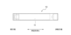
- FIG. 2 is a cross-sectional view showing the power supply unit 10 according to the present embodiment.
- FIG. 3 is a cross-sectional view showing the atomization unit 20 according to the present embodiment.
- FIG. 4 is a diagram showing an internal structure of the atomization unit 20 according to the present embodiment. However, it should be noted that in FIG. 4, the reservoir 21 described later is omitted.
- FIG. 5 is a side view showing the cartridge 30 according to the present embodiment.
- FIG. 6 is an exploded perspective view of the cartridge 30 according to the present embodiment.
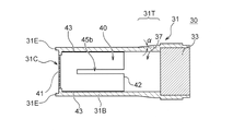
- FIG. 7A is a cross-sectional view (AA cross-sectional view shown in FIG. 5) showing the cartridge 30 according to the present embodiment.
- FIG. 7B is a cross-sectional view of the cartridge 30 in the arrow view 7B-7B shown in FIG. 7A.
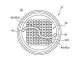
- FIG. 7C is a cross-sectional view (BB cross-sectional view shown in FIG. 7A) showing the cartridge 30 according to the present embodiment.
- the flavor source and the cap 34 are omitted.
- FIG. 7A is a cross-sectional view taken along the central axis CL of the flavor source accommodating body 31.
- the non-combustion type flavor aspirator 1 has a shape extending along a predetermined direction A which is a direction connecting the non-mouthpiece end and the mouthpiece end.
- the flavor aspirator 1 is an instrument for sucking flavor without burning.
- the flavor aspirator 1 has a power supply unit 10, an atomization unit 20, and a cartridge 30 (corresponding to an example of the cartridge).
- the atomization unit 20 is removable from the power supply unit 10, and the cartridge 30 is removable from the atomization unit 20.
- the atomization unit 20 and the cartridge 30 are each replaceable.
- the power supply unit 10 has a shape extending along a predetermined direction A, and has at least a battery 11.
- the battery 11 may be a disposable type battery or a rechargeable type battery.
- the initial value of the output voltage of the battery 11 is preferably in the range of 1.2 V or more and 4.2 V or less.
- the battery capacity of the battery 11 is preferably in the range of 100 mAh or more and 1000 mAh or less.
- the atomization unit 20 has a shape extending along a predetermined direction A.
- the atomization unit 20 has a reservoir 21, an atomization unit 22, a flow path forming body 23, an outer frame body 24, and an end cap 25.
- the atomization unit 20 has a first flow path 20X arranged on the downstream side of the atomization unit 22 as an aerosol flow path extending along a predetermined direction A.
- the side close to the atomizing portion 22 is referred to as an upstream, and the side away from the atomizing portion 22 is referred to as a downstream.
- the reservoir 21 stores the aerosol source 21A.
- the reservoir 21 is located around the flow path forming body 23 in a cross section orthogonal to the first flow path 20X (predetermined direction A). In the present embodiment, the reservoir 21 is located in the gap between the flow path forming body 23 and the outer frame body 24.
- the reservoir 21 is made of, for example, a porous body such as a resin web or cotton. However, the reservoir 21 may be composed of a tank accommodating the liquid aerosol source 21A. Aerosol source 21A contains a liquid such as glycerin or propylene glycol.
- the atomizing unit 22 atomizes the aerosol source 21A by the electric power supplied from the battery 11 without combustion.
- the atomizing unit 22 is composed of heating wires (coils) wound at a predetermined pitch.
- the predetermined pitch is at least a value at which the heating wire does not contact, and is preferably a small value.
- the predetermined pitch is preferably, for example, 0.40 mm or less.
- the predetermined pitch is preferably constant in order to stabilize the atomization of the aerosol source 21A.
- the flow path forming body 23 has a cylindrical shape extending along a predetermined direction A and forming the first flow path 20X.
- the outer frame body 24 extends along a predetermined direction A and has a cylindrical shape for accommodating the flow path forming body 23. In the present embodiment, the outer frame body 24 extends downstream from the end cap 25 and accommodates a part of the cartridge 30.
- the end cap 25 is a cap that closes the gap between the flow path forming body 23 and the outer frame body 24 from the downstream side.
- the end cap 25 suppresses the aerosol source 21A stored in the reservoir 21 from leaking to the cartridge 30 side.
- the cartridge 30 has at least a flavor source (not shown) that imparts flavor to the aerosol generated by the flavor aspirator 1.
- the cartridge 30 is attached to the flavor aspirator 1.
- the cartridge 30 is connected to the atomization unit 20. Specifically, a part of the cartridge 30 is housed in the outer frame body 24 of the atomization unit 20 as described above.
- the cartridge 30 has a shape extending along a predetermined direction A. Specifically, the cartridge 30 has a flavor source accommodating body 31, a filter 33 (corresponding to an example of the top wall), and a cap 34. The cartridge 30 has a second flow path 30X arranged downstream of the first flow path 20X as an aerosol flow path.
- the filter 33 is composed of predetermined fibers and has a roughness to the extent that the raw material piece of the flavor source does not pass through.
- the filter 33 is arranged downstream from the flavor source.
- the filter 33 is, for example, an acetate filter.
- the cap 34 is provided downstream (on the mouthpiece side) of the filter 33.
- the flavor source container 31, the filter 33, and the cap 34 are preferably bonded or welded to each other.
- the cartridge 30 imparts a flavor to the aerosol by passing the aerosol atomized by the atomizing unit 22.
- the aerosol can be flavored without heating the flavor source. It should also be noted that substantially no aerosol is generated from the flavor source. However, the flavor source may be heated. In this case, it is preferable that the flavor source is heated at a low temperature at which an aerosol is not generated.
- the maximum size of the cartridge 30 is preferably 40 mm or less. Further, in the predetermined direction A, the maximum size of the cartridge 30 is preferably 25 mm or less. On the other hand, in the predetermined direction A, the minimum size of the cartridge 30 is preferably 5 mm or more. Further, in the predetermined direction A, the minimum size of the cartridge 30 is preferably 1 mm or more. The maximum size of the cartridge 30 is preferably 20 mm or less in the direction orthogonal to the predetermined direction A. Further, the maximum size of the cartridge 30 is preferably 10 mm or less in the direction orthogonal to the predetermined direction A. On the other hand, the minimum size of the cartridge 30 is preferably 3 mm or more in the direction orthogonal to the predetermined direction A. Further, the minimum size of the cartridge 30 is preferably 1 mm or more in the direction orthogonal to the predetermined direction A.
- the flavor source accommodating body 31 has a cylindrical portion 31B and a bottom wall 31C provided at at least one end of the tubular portion 31B, and forms a second flow path 30X extending along a predetermined direction A.
- the tubular portion 31B has a substantially cylindrical shape, but is not limited to this, and may have an arbitrary tubular shape such as a square tubular shape.
- the bottom wall 31C has a mesh portion 32.
- the mesh portion 32 has an opening size that allows the aerosol generated in the atomizing portion 22 to pass through and does not allow the raw material piece of the flavor source in the flavor source container 31 to pass through.
- the bottom wall 31C is provided only on the upstream side of the tubular portion 31B, but is not limited to this, and may be provided on the downstream side of the tubular portion 31B. That is, a wall provided with the mesh portion 32 (corresponding to an example of the top wall) may be provided at a position where the filter 33 of the tubular portion 31B is provided. Further, in the illustrated embodiment, the bottom wall 31C is provided so that the wall surface thereof is substantially orthogonal to the predetermined direction A (or the axial direction of the tubular portion 31B), but the bottom wall 31C is not limited to this and is provided in the predetermined direction A. It may be provided so as to incline with respect to it. In this case, the mesh portion 32 provided on the bottom wall 31C is also provided so as to be inclined with respect to the predetermined direction A.
- the flavor source accommodating body 31 has a flavor source accommodating space 37 for accommodating the flavor source.
- the flavor source accommodating space 37 means a space surrounded by the tubular portion 31B, the bottom wall 31C, and the filter 33.
- the flavor source that imparts flavor to the aerosol is housed in the second flow path 30X.
- the size of the first flow path 20X is small.
- the size of the second flow path 30X is the above-mentioned first. It tends to be larger than the size of the flow path 20X.
- the flavor source is composed of raw material pieces that impart flavor to the aerosol generated by the flavor aspirator 1.
- the lower limit of the size of the raw material piece is preferably 0.2 mm or more and 1.2 mm or less. Further, the lower limit of the size of the raw material piece is preferably 0.2 mm or more and 0.7 mm or less.
- the specific surface area increases, so that the flavor component is likely to be released from the raw material piece constituting the flavor source.
- chopped tobacco or a molded product obtained by granulating the tobacco raw material can be used.
- the flavor source may be composed of plants other than tobacco (eg, mint, herbs, etc.).
- a fragrance such as menthol may be added to the flavor source.
- the flavor source accommodating body 31 is an upstream end portion (here) of the flavor source accommodating body 31 in a cross section orthogonal to the aerosol flow path (predetermined direction A). Then, it is preferable to have a protruding portion 31E protruding from the outer edge of the bottom wall 31C) to the upstream side (in the embodiment, the flow path forming body 23 or the end cap 25 side).
- the protrusion 31E may be continuously provided along the outer edge of the upstream end portion (here, the bottom wall 31C) of the flavor source accommodating body 31, and may be provided intermittently along the outer edge of the flavor source accommodating body 31. It may be provided.
- the outer surface of the tubular portion 31B of the flavor source accommodating body 31 includes a tapered portion 31T extending from the upstream to the downstream as shown in FIGS. 6 and 7.
- the tapered portion 31T may be included in a part of the outer surface of the tubular portion 31B.
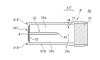
- the taper angle ⁇ of the tapered portion 31T is, for example, about 5 degrees.
- the flavor source container 31 can be formed of, for example, a resin.
- a resin for example, one or more resins selected from polypropylene, polyethylene terephthalate, polyethylene resin and ABS resin can be used. From the viewpoint of moldability and texture, the resin is preferably polypropylene.
- the flavor source container 31 can be formed by mold molding or injection molding.
- the tubular portion 31B and the bottom wall 31C may be integrally formed, or may be a separate tubular portion 31B and a bottom wall 31C, respectively.
- the bottom wall 31C of the present embodiment has a mesh portion 32 including a plurality of openings 32A.
- Each of the plurality of openings 32A is not limited to the substantially rectangular shape shown in FIG. 7C, and may have any shape such as a circle, an ellipse, a square, a rhombus, a hexagon, and an octagon. From the viewpoint of arrangement efficiency and ease of manufacture of the plurality of openings 32A, it is preferable that each of the plurality of openings 32A has a quadrangular shape. It is preferable that the plurality of openings 32A are arranged so that the sides of the openings 32A adjacent to each other are parallel to each other. Further, the distance between the openings 32A adjacent to each other is preferably 0.15 mm or more and 0.30 mm or less. In such a case, the thickness of the mesh portion 32 is preferably 0.1 mm or more and 1 mm or less.
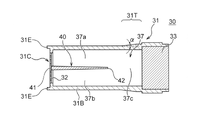
- the cartridge 30 has a flavor source accommodating space 37 in order to prevent the flavor source from being biased according to the usage mode of the flavor aspirator 1. It has a partition wall 40 provided inside.
- the partition wall 40 has a first end portion 41 on the upstream side, a second end portion 42 on the downstream side, and at least two side end portions 43.
- the first end portion 41 is configured to be in contact with at least a part of the bottom wall 31C, and both ends thereof are in contact with the tubular portion 31B.
- the first end 41 of the partition wall 40 may not be in contact with the bottom wall 31C but may be in close proximity to the bottom wall 31C.
- the second end portion 42 is an end portion facing the first end portion 41, and at least a part thereof is configured to be separated from the filter 33.
- the two side end portions 43 are at least partially in contact with the tubular portion 31B at at least two different positions in the circumferential direction, respectively.
- the partition wall 40 has two side end portions 43, and the two side end portions 43 are in contact with the tubular portion 31B at positions facing each other. That is, in the illustrated example, the partition wall 40 is a flat plate-like body, and the thickness of the partition wall 40 is constant in the entire partition wall 40. It is preferable that each of the side end portions 43 is in contact with the tubular portion 31B over the entire length thereof.
- the partition wall 40 may be integrally formed with the tubular portion 31B. Further, the partition wall 40 may be formed integrally with the bottom wall 31C.
- the partition wall 40 may be a separate member from the tubular portion 31B and / or the bottom wall 31C. When the partition wall 40 is a separate member from the tubular portion 31B and the bottom wall 31C, the partition wall 40 may be inserted into the tubular portion 31B. In this case, the tubular portion 31B may have a groove on the inner surface thereof into which the partition wall 40 is inserted and guides the partition wall 40.
- FIG. 7A the partition wall 40 is arranged in the flavor source accommodating space 37, so that the first space 37a and the second space 37b are formed between the partition wall 40 and the tubular portion 31B. Further, a third space 37c communicating with the first space 37a and the second space 37b is formed between the partition wall 40 and the filter 33.
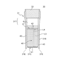
- FIG. 8 is a cross-sectional view of the flavor source accommodating body 31 in a state where the flavor source 31A is accommodated in the flavor source accommodating space 37.
- FIG. 8 shows a state in which the flavor source accommodating body 31 accommodating the flavor source 31A is arranged so as to face the horizontal direction in the first space 37a and the second space 37b.
- the cartridge 30 of the present embodiment has a partition wall 40 in the flavor source accommodating space 37, as shown in FIG. 8, even if the flavor source accommodating body 31 is arranged sideways, a part of the flavor source 31A is a partition wall 40. Supported by. As a result, it is possible to prevent the flavor source 31A in the cartridge 30 from being biased downward in the vertical direction.
- the first space at the time of manufacturing the cartridge 30 It is necessary to adjust the amount of the flavor source 31A, such as equalizing the amount of the flavor source 31A contained in the 37a and the second space 37b.
- the flavor source 31A passes through the third space 37c to the first space 37a and the second space 37b. You can move between and.
- the first end portion 41 of the partition wall 40 is in contact with the bottom wall 31C over its entire length.
- the flavor source 31A is in the vertical direction.
- the downward bias can be suppressed.
- the flavor source 31A located in the vicinity of the bottom wall 31C can be suppressed from moving between the first space 37a and the second space 37b.
- the first end portion 41 of the partition wall 40 since there is a step on the bottom wall 31C near the connection point between the bottom wall 31C and the tubular portion 31B, the first end portion 41 of the partition wall 40 also corresponds to the step on the bottom wall 31C. Then, it is in contact with the bottom wall 31C over its entire length.
- the second end portion 42 of the partition wall 40 is separated from the filter 33 over the entire length thereof.
- the area through which the flavor source 31A passes between the partition wall 40 and the filter 33 can be widened.
- the bias of the flavor source 31A can be easily eliminated by shaking the cartridge 30.
- the partition wall 40 extends in parallel with the axial direction (predetermined direction A) of the tubular portion 31B.
- the partition wall 40 preferably extends on the central axis CL of the tubular portion 31B.
- the partition wall 40 has a length L1 in the axial direction of the tubular portion 31B.
- the flavor source accommodating space 37 has a length L2 in the axial direction of the tubular portion 31B.
- the length L1 of the partition wall 40 may be 10% or more, preferably 20% or more, and more preferably 30% or more of the length L2 of the flavor source accommodating space 37.
- the length L1 of the partition wall 40 may be 70% or less, preferably 60% or less, and more preferably 50% or less of the length L2 of the flavor source accommodating space 37. Therefore, the length L1 of the partition wall 40 is preferably 10% or more and 70% or less of the length L2 of the flavor source accommodating space 37.
- the flavor source 31A When the length L1 of the partition wall 40 is less than 10% of the length L2 of the flavor source accommodating space 37, the flavor source 31A is tilted from the vertically oriented state to the horizontally oriented state. It may not be possible to sufficiently suppress the downward bias in the vertical direction. Further, if the length L1 of the partition wall 40 is more than 70% of the length L2 of the flavor source accommodating space 37, the flavor source accommodating space 37 may become small and the cartridge 30 may not be able to accommodate a sufficient amount of the flavor source 31A. be. Further, the fluidity of the flavor source 31A in the cartridge 30 may be deteriorated. As shown in FIG.
- the length L1 of the partition wall 40 and the length L2 of the flavor source accommodating space 37 are the length L1 of the cross section of the partition wall 40 and the flavor source accommodating space at the position corresponding to this cross section. It refers to the length L2 of 37.
- FIG. 9 is a cross-sectional view of the flavor source container 31 in a state where the flavor source 31A is housed in the flavor source storage space 37.
- FIG. 9 shows a state in which the flavor source accommodating body 31 is oriented so that the axial direction of the flavor source accommodating body 31 coincides with the vertical direction. That is, FIG. 9 shows a state in which the flavor source 31A is supported by the bottom wall 31C.
- the partition wall 40 has a maximum length L3 in the axial direction of the tubular portion 31B.
- the space in which the flavor source 31A exists has a maximum length L4 in the axial direction of the tubular portion 31B.
- the maximum length L4 of the space in which the flavor source 31A is present is preferably longer than the maximum length L3 of the partition wall 40.
- the flavor source 31A is housed in the flavor source container 31 so that the flavor source 31A has a height exceeding the second end portion 42 of the partition wall 40.
- the volume of the flavor source accommodating space 37 can be secured.
- the flavor source container 31 is filled with the flavor source 31A or when the cartridge 30 is used, it is possible to prevent the flavor source 31A from being biased toward the first space 37a or the second space 37b.
- FIGS. 10B and 10C show a cross-sectional view at the same position as FIG. 7B.
- the partition wall 40 of the cartridge 30 has irregularities on its wall surface 45.
- the partition wall 40 may have irregularities formed on the wall surface 45 by having at least one convex portion 45a on the wall surface 45.
- the cartridge 30 when the cartridge 30 is directed from the vertical direction to the horizontal direction, the movement of the flavor source 31A is suppressed by the unevenness, and the flavor source 31A can be effectively supported by the partition wall 40. Further, due to the unevenness of the wall surface 45 of the partition wall 40, it is possible to suppress the movement of the flavor source 31A from the first space 37a or the second space 37b located upward in the vertical direction to the third space 37c at the time of suction by the user. You can expect it.
- the partition wall 40 of the cartridge 30 has a groove 45b (slit) on the wall surface 45 thereof.
- the groove 45b extends to the second end 42 and is substantially notched.
- the partition wall 40 of the cartridge 30 has an opening 45c in its wall surface 45.
- 11A and 11B are cross-sectional views showing the flavor source accommodating body 31 of the cartridge 30 according to each of the other embodiments. 11A and 11B show cross-sectional views at positions similar to FIG. 7C.
- the partition wall 40 has a central portion 46 located separated from the two side end portions 43.
- the cartridge 30 shown in FIG. 7C had a partition wall 40 having a constant thickness as a whole.
- at least one of the two side end portions 43 of the partition wall 40 is thicker than the central portion 46.
- the two side end portions 43 are formed to be thicker than the central portion 46.
- the partition wall 40 has a portion whose thickness gradually decreases from the side end portion 43 toward the central portion 46.
- the partition wall 40 has a portion whose thickness continuously decreases from the side end portion 43 toward the central portion 46.
- the side end portion 43 in contact with the tubular portion 31B is formed to be relatively thick, so that when the tubular portion 31B and the side end portion 43 are integrally formed, etc. , The connection point between the partition wall 40 and the tubular portion 31B can be suppressed from being broken.
- FIG. 12 is a cross-sectional view showing a flavor source accommodating body 31 of the cartridge 30 according to another embodiment.
- FIG. 12 shows a cross-sectional view at the same position as in FIG. 7C.
- the partition wall 40 has a curved surface 45d on its wall surface 45.
- the wall surface 45 refers to the surface of the partition wall 40 extending between the two side end portions 43.
- the partition wall 40 is formed in a curved plate shape as a whole because the two facing wall surfaces 45 have a curved surface 45d.
- 13A to 13C are cross-sectional views showing a flavor source accommodating body 31 of the cartridge 30 according to another embodiment.
- 13A to 13C show cross-sectional views at the same positions as in FIG. 7A.
- the thickness of the partition wall 40 was constant in the entire partition wall 40.
- the partition wall 40 is formed so that the thickness of the partition wall 40 decreases from the first end portion 41 toward the second end portion 42. Since the thickness of the partition wall 40 is relatively thick at the connection point of the partition wall 40 with the bottom wall 31C, the strength of the connection point between the partition wall 40 and the bottom wall 31C can be improved.
- the second end portion 42 of the partition wall 40 is thinner than the first end portion 41, the volume of the flavor source accommodating space 37 can be increased as compared with the case where the length of the partition wall 40 is constant.
- the second end portion 42 of the partition wall 40 is formed in a square shape. Specifically, in the embodiment shown in FIG. 13B, the cross section of the second end portion 42 of the partition wall 40 on the plane parallel to the axial direction of the tubular portion 31B is angular. In the embodiment shown in FIG. 13C, the second end portion 42 of the partition wall 40 is formed in a round shape. Specifically, in the embodiment shown in FIG. 13C, the cross section of the second end portion 42 of the partition wall 40 on the plane parallel to the axial direction of the tubular portion 31B is round.
- 14A and 14B are cross-sectional views showing a flavor source accommodating body 31 of the cartridge 30 according to another embodiment. 14A and 14B show cross-sectional views at the same positions as FIG. 7B.
- the second end 42 of the bulkhead 40 extends non-linearly from one of the two side ends 43 towards the other of the two side ends 43.
- the second end portion 42 of the partition wall 40 is formed in a non-linear manner in the plan view of the partition wall 40 shown in FIGS. 14A and 14B.
- the second end portion 42 extends from one of the two side end portions 43 toward the other of the two side end portions 43 in a substantially arc shape.
- FIG. 14A the second end portion 42 extends from one of the two side end portions 43 toward the other of the two side end portions 43 in a substantially arc shape.
- the second end portion 42 extends substantially angularly from one of the two side end portions 43 toward the other of the two side end portions 43.
- non-linear means that the linear shape is not linear, and as in the example shown in FIG. 14B, there are a plurality of spaces between one side end portion 43 and the other side end portion 43 (in FIG. 14B).
- the case of connecting with two) straight lines is also called “non-straight line”.
- FIG. 15 is a cross-sectional view showing a flavor source accommodating body 31 of the cartridge 30 according to another embodiment.
- the cartridge 30 has two bulkheads 40.
- the flavor source 31A is supported by the respective partition walls 40, and it is possible to further suppress the flavor source 31A from being biased downward in the vertical direction.
- the cartridge 30 preferably has one or more and three or less partition walls 40. When the number of partition walls 40 exceeds 4, the effect of suppressing the flavor source 31A from being biased downward in the vertical direction is not significantly improved, while the flavor source accommodating space 37 becomes smaller and the cartridge 30 has a sufficient amount of flavor source 31A. May not be able to be accommodated.
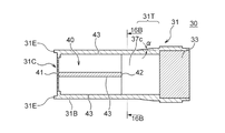
- FIG. 16A is a cross-sectional view showing a flavor source accommodating body 31 of the cartridge 30 according to another embodiment.
- FIG. 16B is a cross-sectional view (16B-16B cross-sectional view shown in FIG. 16A) showing the cartridge 30 according to the present embodiment.
- the partition wall 40 has four side end portions 43. The four side end portions 43 are in contact with the tubular portion 31B at different positions in the circumferential direction. Specifically, the four side end portions 43 are in contact with the tubular portion 31B in different circumferential directions by 90 °.
- the partition wall 40 has a cross-shaped second end portion 42 when viewed from the axial direction.
- the partition wall 40 can support the flavor source 31A even if the cartridge 30 is tilted in any direction when the cartridge 30 is oriented from the vertical direction to the horizontal direction. It is possible to further suppress the flavor source 31A from being biased downward in the vertical direction.
- Flavor aspirator 30 Cartridge 31: Flavor source accommodating body 31A: Flavor source 31B: Cylindrical portion 31C: Bottom wall 37: Flavor source accommodating space 40: Partition wall 41: First end portion 42: Second end portion 43: Side end 45: Wall surface 45b: Groove 45c: Opening 45d: Curved surface 46: Central CL: Central axis
Landscapes
- Cigarettes, Filters, And Manufacturing Of Filters (AREA)
Priority Applications (2)
| Application Number | Priority Date | Filing Date | Title |
|---|---|---|---|
| PCT/JP2020/045631 WO2022123650A1 (ja) | 2020-12-08 | 2020-12-08 | カートリッジ |
| JP2022567920A JPWO2022123650A1 (https=) | 2020-12-08 | 2020-12-08 |
Applications Claiming Priority (1)
| Application Number | Priority Date | Filing Date | Title |
|---|---|---|---|
| PCT/JP2020/045631 WO2022123650A1 (ja) | 2020-12-08 | 2020-12-08 | カートリッジ |
Publications (1)
| Publication Number | Publication Date |
|---|---|
| WO2022123650A1 true WO2022123650A1 (ja) | 2022-06-16 |
Family
ID=81973374
Family Applications (1)
| Application Number | Title | Priority Date | Filing Date |
|---|---|---|---|
| PCT/JP2020/045631 Ceased WO2022123650A1 (ja) | 2020-12-08 | 2020-12-08 | カートリッジ |
Country Status (2)
| Country | Link |
|---|---|
| JP (1) | JPWO2022123650A1 (https=) |
| WO (1) | WO2022123650A1 (https=) |
Citations (6)
| Publication number | Priority date | Publication date | Assignee | Title |
|---|---|---|---|---|
| JP2018516536A (ja) * | 2015-03-31 | 2018-06-28 | ブリティッシュ アメリカン タバコ (インヴェストメンツ) リミテッドBritish American Tobacco (Investments) Limited | 喫煙材を加熱するための装置に使用する物品 |
| JP2018527888A (ja) * | 2015-08-17 | 2018-09-27 | フィリップ・モーリス・プロダクツ・ソシエテ・アノニム | エアロゾル発生システムおよびそのシステムにおける使用のためのエアロゾル発生物品 |
| JP2018528788A (ja) * | 2015-08-21 | 2018-10-04 | フィリップ・モーリス・プロダクツ・ソシエテ・アノニム | エアロゾル発生システム用カートリッジ組立品およびカートリッジ組立品を含むエアロゾル発生システム |
| WO2018216430A1 (ja) * | 2017-05-26 | 2018-11-29 | 日本たばこ産業株式会社 | 香味源ユニット及び香味吸引器 |
| JP2019526242A (ja) * | 2016-07-29 | 2019-09-19 | フィリップ・モーリス・プロダクツ・ソシエテ・アノニム | ゲルを収容するカートリッジを備えるエアロゾル発生システム |
| JP2019526233A (ja) * | 2016-07-29 | 2019-09-19 | フィリップ・モーリス・プロダクツ・ソシエテ・アノニム | 加熱式ゲル容器を備えるエアロゾル発生システム |
-
2020
- 2020-12-08 WO PCT/JP2020/045631 patent/WO2022123650A1/ja not_active Ceased
- 2020-12-08 JP JP2022567920A patent/JPWO2022123650A1/ja active Pending
Patent Citations (6)
| Publication number | Priority date | Publication date | Assignee | Title |
|---|---|---|---|---|
| JP2018516536A (ja) * | 2015-03-31 | 2018-06-28 | ブリティッシュ アメリカン タバコ (インヴェストメンツ) リミテッドBritish American Tobacco (Investments) Limited | 喫煙材を加熱するための装置に使用する物品 |
| JP2018527888A (ja) * | 2015-08-17 | 2018-09-27 | フィリップ・モーリス・プロダクツ・ソシエテ・アノニム | エアロゾル発生システムおよびそのシステムにおける使用のためのエアロゾル発生物品 |
| JP2018528788A (ja) * | 2015-08-21 | 2018-10-04 | フィリップ・モーリス・プロダクツ・ソシエテ・アノニム | エアロゾル発生システム用カートリッジ組立品およびカートリッジ組立品を含むエアロゾル発生システム |
| JP2019526242A (ja) * | 2016-07-29 | 2019-09-19 | フィリップ・モーリス・プロダクツ・ソシエテ・アノニム | ゲルを収容するカートリッジを備えるエアロゾル発生システム |
| JP2019526233A (ja) * | 2016-07-29 | 2019-09-19 | フィリップ・モーリス・プロダクツ・ソシエテ・アノニム | 加熱式ゲル容器を備えるエアロゾル発生システム |
| WO2018216430A1 (ja) * | 2017-05-26 | 2018-11-29 | 日本たばこ産業株式会社 | 香味源ユニット及び香味吸引器 |
Also Published As
| Publication number | Publication date |
|---|---|
| JPWO2022123650A1 (https=) | 2022-06-16 |
Similar Documents
| Publication | Publication Date | Title |
|---|---|---|
| KR102414585B1 (ko) | 향미원 유닛 및 향미 흡인기 | |
| TWI594704B (zh) | 匣體及非燃燒型香味吸嚐器 | |
| TWI578922B (zh) | 非燃燒型香味吸嚐器 | |
| CN110338466B (zh) | 电子雾化装置及其雾化器、发热组件和多孔陶瓷体 | |
| US8997753B2 (en) | Electronic smoking article | |
| CN107072319B (zh) | 非燃烧式香味吸引器及包装 | |
| JP2019076101A (ja) | 非燃焼型香味吸引器及び制御方法 | |
| KR102768918B1 (ko) | 에어로졸 발생 장치의 세라믹 무화기 | |
| US20220202082A1 (en) | Atomizing unit and non-combustion-heating-type flavor inhaling mechanism | |
| JP7853751B1 (ja) | 加熱式タバコ用の支持部材 | |
| JP7203246B2 (ja) | 霧化ユニット及び非燃焼加熱型香味吸引器具 | |
| WO2022123650A1 (ja) | カートリッジ | |
| JP7256110B2 (ja) | 香味源容器及び非燃焼式吸引器 | |
| JP7789869B2 (ja) | カートリッジ及び非燃焼型香味吸引器 | |
| WO2022123649A1 (ja) | カートリッジ | |
| JP6913193B2 (ja) | カートリッジ及び非燃焼型香味吸引器 | |
| HK1239472A1 (en) | Non-combusting flavor inhaler | |
| HK1239473A1 (en) | Cartridge and non-combusting flavor inhaler |
Legal Events
| Date | Code | Title | Description |
|---|---|---|---|
| 121 | Ep: the epo has been informed by wipo that ep was designated in this application |
Ref document number: 20965035 Country of ref document: EP Kind code of ref document: A1 |
|
| ENP | Entry into the national phase |
Ref document number: 2022567920 Country of ref document: JP Kind code of ref document: A |
|
| NENP | Non-entry into the national phase |
Ref country code: DE |
|
| 122 | Ep: pct application non-entry in european phase |
Ref document number: 20965035 Country of ref document: EP Kind code of ref document: A1 |