WO2022123641A1 - レール検出装置及びレール検出方法 - Google Patents
レール検出装置及びレール検出方法 Download PDFInfo
- Publication number
- WO2022123641A1 WO2022123641A1 PCT/JP2020/045568 JP2020045568W WO2022123641A1 WO 2022123641 A1 WO2022123641 A1 WO 2022123641A1 JP 2020045568 W JP2020045568 W JP 2020045568W WO 2022123641 A1 WO2022123641 A1 WO 2022123641A1
- Authority
- WO
- WIPO (PCT)
- Prior art keywords
- rail
- area
- correction
- region
- rails
- Prior art date
- Legal status (The legal status is an assumption and is not a legal conclusion. Google has not performed a legal analysis and makes no representation as to the accuracy of the status listed.)
- Ceased
Links
Images









Classifications
-
- G—PHYSICS
- G06—COMPUTING OR CALCULATING; COUNTING
- G06V—IMAGE OR VIDEO RECOGNITION OR UNDERSTANDING
- G06V10/00—Arrangements for image or video recognition or understanding
- G06V10/20—Image preprocessing
- G06V10/255—Detecting or recognising potential candidate objects based on visual cues, e.g. shapes
-
- B—PERFORMING OPERATIONS; TRANSPORTING
- B60—VEHICLES IN GENERAL
- B60R—VEHICLES, VEHICLE FITTINGS, OR VEHICLE PARTS, NOT OTHERWISE PROVIDED FOR
- B60R21/00—Arrangements or fittings on vehicles for protecting or preventing injuries to occupants or pedestrians in case of accidents or other traffic risks
-
- B—PERFORMING OPERATIONS; TRANSPORTING
- B61—RAILWAYS
- B61L—GUIDING RAILWAY TRAFFIC; ENSURING THE SAFETY OF RAILWAY TRAFFIC
- B61L23/00—Control, warning or like safety means along the route or between vehicles or trains
-
- G—PHYSICS
- G06—COMPUTING OR CALCULATING; COUNTING
- G06T—IMAGE DATA PROCESSING OR GENERATION, IN GENERAL
- G06T7/00—Image analysis
- G06T7/60—Analysis of geometric attributes
-
- G—PHYSICS
- G06—COMPUTING OR CALCULATING; COUNTING
- G06V—IMAGE OR VIDEO RECOGNITION OR UNDERSTANDING
- G06V10/00—Arrangements for image or video recognition or understanding
- G06V10/20—Image preprocessing
- G06V10/26—Segmentation of patterns in the image field; Cutting or merging of image elements to establish the pattern region, e.g. clustering-based techniques; Detection of occlusion
- G06V10/267—Segmentation of patterns in the image field; Cutting or merging of image elements to establish the pattern region, e.g. clustering-based techniques; Detection of occlusion by performing operations on regions, e.g. growing, shrinking or watersheds
-
- G—PHYSICS
- G06—COMPUTING OR CALCULATING; COUNTING
- G06V—IMAGE OR VIDEO RECOGNITION OR UNDERSTANDING
- G06V10/00—Arrangements for image or video recognition or understanding
- G06V10/40—Extraction of image or video features
- G06V10/44—Local feature extraction by analysis of parts of the pattern, e.g. by detecting edges, contours, loops, corners, strokes or intersections; Connectivity analysis, e.g. of connected components
- G06V10/457—Local feature extraction by analysis of parts of the pattern, e.g. by detecting edges, contours, loops, corners, strokes or intersections; Connectivity analysis, e.g. of connected components by analysing connectivity, e.g. edge linking, connected component analysis or slices
-
- G—PHYSICS
- G06—COMPUTING OR CALCULATING; COUNTING
- G06V—IMAGE OR VIDEO RECOGNITION OR UNDERSTANDING
- G06V20/00—Scenes; Scene-specific elements
- G06V20/50—Context or environment of the image
-
- G—PHYSICS
- G06—COMPUTING OR CALCULATING; COUNTING
- G06V—IMAGE OR VIDEO RECOGNITION OR UNDERSTANDING
- G06V20/00—Scenes; Scene-specific elements
- G06V20/50—Context or environment of the image
- G06V20/56—Context or environment of the image exterior to a vehicle by using sensors mounted on the vehicle
-
- G—PHYSICS
- G06—COMPUTING OR CALCULATING; COUNTING
- G06V—IMAGE OR VIDEO RECOGNITION OR UNDERSTANDING
- G06V20/00—Scenes; Scene-specific elements
- G06V20/50—Context or environment of the image
- G06V20/56—Context or environment of the image exterior to a vehicle by using sensors mounted on the vehicle
- G06V20/588—Recognition of the road, e.g. of lane markings; Recognition of the vehicle driving pattern in relation to the road
Definitions
- the rail can be detected accurately even if there is an obstacle such as a shadow around the rail.
- the rail detection device 110 is a device that detects a rail from an image shown by moving image data obtained from the image pickup device 101. For example, the rail detection device 110 detects a rail portion by detecting a rail portion which is a rail portion from an image and connecting the rail portions. Specifically, the rail detection device 110 divides an image including two rails into a plurality of regions, and detects a plurality of rail portions, which are a plurality of portions of the two rails, from the plurality of regions. Then, the rail detection device 110 detects two rails by connecting the plurality of rail portions.
- the moving image input unit 130 accepts the input of moving image data from the image pickup device 101.
- the rail detection area designation unit 131 designates the area including the two rails as the rail detection area from the image including the two rails.
- the rail detection area designation unit 131 designates a rail detection area from a one-frame image shown by moving image data.
- the rail detection area designation unit 131 designates a predetermined area of the image as the rail detection area. For example, since the rail does not exist at the upper part of the image due to the position and orientation of the image pickup apparatus 101, the rail detection area designation unit 131 designates a certain area at the lower part of the image as the rail detection area.
- the rail detection area division unit 132 divides the rail detection area into a plurality of division areas in the vertical direction. Then, the rail detection area division unit 132 includes three or more consecutive division areas, and generates a plurality of rail candidate detection areas so that two adjacent rail candidate detection areas overlap in at least one division area. ..
- the rail detection area dividing unit 132 generates six or more divided areas by dividing the rail detection area into at least six or more. Then, it is desirable that the rail detection area division unit 132 generate at least two or more rail candidate detection areas by at least three or more division areas so that at least one division area overlaps.
- the target distance can be calculated by the above equation (1).
- the target position x coordinate (pixel) can be calculated by the equation (2).
- the rail gauge and the rail head width are also fixed and known, the x-coordinates and y-coordinates of the four points as the starting points of the rail in the starting region can be calculated.
- the start area rail selection unit 135 selects the rail candidate whose lowest end is closest to the start point specified by the start area rail start point designation unit 134 as the temporary rail portion which is the temporary rail portion of the start region. do.
- FIG. 6 is a schematic diagram for explaining a processing example for determining whether or not the temporary rail portion in the start region has disappeared.
- the start area rail disappearance determination unit 136 selects one start point as the target start point TP in order from the four start points P1 to P4. Then, the temporary rail portion that is the rail candidate closest to the target start point TP is referred to as the target temporary rail portion TT.
- the start region rail disappearance determination unit 136 reaches the target temporary rail at the target start point.
- the part is not fixed as the rail part.
- the threshold value here may be determined based on the width of the rail head. For example, by setting the threshold value to the rail head width, it can be determined that the rail portion is not properly detected when the width is equal to or larger than such a width. This is the case, for example, as shown in FIG. 6, when the lowermost end of the target temporary rail portion TT does not exist inside the circle C indicating the threshold value centered on the target start point TP. It is shown that the target temporary rail part does not become the rail part.
- start area rail disappearance determination unit 136 determines that the rail has disappeared
- start area rail start point redesignation unit 137 shifts the start area to the next rail candidate detection area and newly sets the start point. specify.
- the start area rail start point redesignation unit 137 shifts the start area upward when both parts of the two rails are not detected by the rail part.
- the start area shifted upward is also referred to as a correction start area.
- the start area rail start point redesignation unit 137 designates a point at a predetermined position on the lower side of the correction start area as the start point of the two rails.
- the starting point specified here is also called the correction starting point.
- FIG. 7 is a schematic diagram for explaining a process of redesignating the start point of the start region.
- the start area rail start point redesignation unit 137 designates the next rail candidate detection area R12 as the start area when it is determined that the rail has disappeared when the rail candidate detection area R11 is designated as the start area SR. Then, the start area rail start point redesignation unit 137 designates four start points in the designated start area, similarly to the start area rail start point designation unit 134.
- the start region rail start point redesignation unit 137 shifts the start region in order from the bottom to the top of the plurality of rail candidate detection regions when it is determined that the rail has disappeared. This makes it possible to avoid the effects of obstacles.
- the rail candidate detection unit 133 uses the start region or the correction start region as the front region and the rail candidate detection region immediately above the front region as the next region. Then, the rail candidate detection unit 133 detects a plurality of lines that are candidates for the edges of the two rails as a plurality of rail candidates in the next region.
- the rail candidate detected here is also referred to as a next rail candidate.
- the rail candidate detection unit 133 sets the next region as the previous region, and also sets the rail candidate detection region one above the next region, in other words, the next region.
- the rail candidate detection area that overlaps and the rail portion has not been determined is defined as the next area. Then, the rail candidate detection unit 133 detects a plurality of lines that are candidates for the edges of the two rails as a plurality of rail candidates in the next region.
- the next region rail selection unit 138 selects rail candidates in the next region. For example, the next region rail selection unit 138 designates the intersection of the lower side of the next region and the rail portion or the modified rail portion as the starting point of the rail. The starting point specified here is also referred to as the next starting point. Then, the next area rail selection unit 138 selects the next rail candidate whose inclination difference from the rail portion or the modified rail portion is less than the second threshold value among the plurality of next rail candidates as the selected next rail candidate. Further, the next region rail selection unit 138 selects, among the selection next rail candidates, the selection next rail candidate whose lowest end is closest to the next start point as the provisional rail portion.
- next region rail selection unit 138 compares the inclination difference between the rail candidate detected in the next region and the rail portion determined in the previous region using a threshold value, and the rail candidate in the next region is compared. Narrow down.
- the narrowed-down rail candidate is also referred to as a selected rail candidate or a selected next rail candidate.
- FIG. 8 is a schematic diagram for explaining a process of narrowing down rail candidates.
- reference numeral DT indicates a fixed rail portion in the front region.
- Reference numerals CT1 and CT2 indicate rail candidates detected in the next region.
- the rail candidate CT1 and the rail candidate CT2 are excluded from the selected rail candidate or the selected next rail candidate because the inclination difference thereof is equal to or more than the threshold value with respect to the rail portion DT.
- the threshold value at this time may be calculated from the maximum curvature of the curve of the rail (radius R: 160 m).
- the starting point and the lowermost end of the narrowed rail candidates are the farthest distance from the narrowed down rail candidates, with the intersection of the rail portion determined in the previous region and the lowest side of the next region as the starting point.
- the rail candidate that is close to is the temporary rail part.
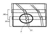
- FIG. 9 is a schematic diagram for explaining a process of specifying a starting point in the next region. As shown in FIG. 9, the intersection P between the rail portion DT determined in the previous region RT and the lowermost end of the next region NR is specified as the starting point.
- next region rail disappearance determination unit 139 determines the temporary rail portion as the rail portion when the distance between the lowermost end of the temporary rail portion and the next start point is less than the first threshold value. do.
- the rail portion determined here is also referred to as the next rail portion. Then, the next region rail disappearance determination unit 139 determines whether or not both portions of the two rails are detected by the next rail portion.
- next region rail start point redesignation unit 140 shifts the next region downward when both portions of the two rails are not detected by the next rail portion.
- the next area shifted here is also referred to as a modified next area.
- the next region rail start point redesignation unit 140 may set the modified next region so that the divided region immediately below the next region is included. In this case, since one rail candidate detection area moves down by the amount of one division area, the rail detection area division unit 132 resets the rail candidate detection area again. Then, the next region rail start point redesignation unit 140 designates the intersection of the lower side of the modified next region and the rail portion or the modified rail portion as the starting point.
- the starting point specified here is also called the modified next starting point.
- next region rail selection unit 138 selects, among the selection correction next rail candidates, the selection correction next rail candidate whose lowest end is closest to the correction next start point as the temporary rail portion.
- the temporary rail part selected here is also referred to as a temporary correction next rail part.
- the next region rail disappearance determination unit 139 determines the provisional correction next rail portion as the rail portion. do.
- the rail portion determined here is also referred to as a modified next rail portion.
- the next region rail disappearance determination unit 139 determines whether or not both portions of the two rails are detected by the modified next rail portion.
- FIG. 12 is a block diagram schematically showing a hardware configuration of the rail detection device 110.
- the rail detection device 110 includes a processor 151 such as a CPU (Central Processing Unit), a memory 152, an auxiliary storage device 153 such as an HDD (Hard Disk Drive) or SSD (Solid State Drive), and an interface (hereinafter, I / F). It can be realized by a computer 150 equipped with 154 and I / F 155.
- a processor 151 such as a CPU (Central Processing Unit)
- a memory 152 such as a RAM (Central Processing Unit)
- an auxiliary storage device 153 such as an HDD (Hard Disk Drive) or SSD (Solid State Drive)
- I / F interface
- rail detection area designation unit 131 For example, rail detection area designation unit 131, rail detection area division unit 132, rail candidate detection unit 133, start area rail start point designation unit 134, start area rail selection unit 135, start area rail disappearance determination unit 136, start area rail start.
- the processor 151 is stored in the auxiliary storage device 153. This can be realized by reading the read program into the memory 152 and executing the read program.
- the moving image input unit 130 can be realized by the I / F 154.
- the I / F 154 is, for example, an interface for exchanging data with the image pickup apparatus 101.
- the rail detection result output unit 142 can be realized by the I / F 155.
- the I / F 155 is, for example, an interface for exchanging data with the display device 102.
- the storage unit 120 can be realized by the auxiliary storage device 153.
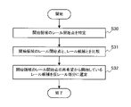
- FIG. 13 and 14 are flowcharts showing a process of detecting a rail in an image of a certain frame. When a moving image is input, the following processing is repeated.
- start area rail start point designation unit 134 designates the start point of the rail in the start area (S14).
- the start area rail selection unit 135 selects the rail candidate closest to the designated start point as the temporary rail portion of the start area (S15).
- step S18 the rail candidate detection unit 133, the start area rail selection unit 135, and the start area rail start point redesignation unit 137 perform rail reselection processing in the start area.
- the processing here will be described in detail with reference to FIG.
- next region rail selection unit 138 specifies the previous region and the next region, selects rail candidates in the next region, and specifies the temporary rail portion in the next region.
- next region rail disappearance determination unit 139 identifies a temporary rail portion that satisfies the rail condition of the next region, and determines whether or not the rail has disappeared in the next region based on the temporary rail portion (S21). If the rail disappears (Yes in S21), the process proceeds to step S22, and if the rail has not disappeared (No in S21), the process proceeds to step S24.
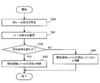
- step S43 the start area rail disappearance determination unit 136 determines that the rail has disappeared in the start area.
- step S44 the start region rail disappearance determination unit 136 determines that the rail has not disappeared in the start region.
- FIG. 18 is a flowchart showing the processing in the next area rail selection unit 138.
- the next region rail selection unit 138 identifies the rail portion determined in the previous region (S60).
- the next region rail selection unit 138 compares the inclination of the rail portion determined in the previous region with the inclination of the rail candidate in the next region (S61).
- the next area rail selection unit 138 excludes rail candidates whose inclination difference between the inclination of the rail portion determined in the previous area and the inclination of the rail candidate in the next area is equal to or larger than a predetermined threshold value from the selected rail candidates. (S62).
- the next region rail disappearance determination unit 139 determines whether or not the distance between the start point and the lowermost end of the temporary rail portion corresponding to the start point is equal to or greater than a predetermined threshold value, so that the distance can be determined.
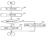
- a temporary rail portion less than the threshold value is specified as a rail portion (S71).
- next area rail disappearance determination unit 139 determines whether or not the disappearance condition is satisfied (S72). If the disappearance condition is satisfied (Yes in S72), the process proceeds to step S73, and if the disappearance condition is not satisfied (No in S72), the process proceeds to step S74.
Landscapes
- Engineering & Computer Science (AREA)
- Physics & Mathematics (AREA)
- General Physics & Mathematics (AREA)
- Theoretical Computer Science (AREA)
- Multimedia (AREA)
- Computer Vision & Pattern Recognition (AREA)
- Mechanical Engineering (AREA)
- Geometry (AREA)
- Image Analysis (AREA)
- Train Traffic Observation, Control, And Security (AREA)
- Electric Propulsion And Braking For Vehicles (AREA)
- Image Processing (AREA)
Abstract
Description
レール検出システム100は、撮像装置101と、表示装置102と、レール検出装置110とを備える。
表示装置102は、レール検出装置110での検出結果を示す画面画像を表示する。
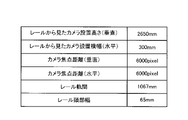
例えば、記憶部120は、レール検出領域指定部131及び開始領域レール開始点指定部134で用いるカメラ設置位置情報、カメラ内部パラメータ及びレール情報を記憶する。
図2に示されているように、記憶部120は、レールから見たカメラ設置高さ(垂直)、レールから見たカメラ設置横幅(水平)、カメラ焦点距離(垂直)、カメラ焦点距離(水平)、レール軌間及びレール頭部幅を記憶している。これらの数値は、事前に取得されているものとする。
ここで、レールから見たカメラ設置高さ(垂直)及びレールから見たカメラ設置横幅(水平)をカメラ設置位置ともいい、カメラ焦点距離(垂直)及びカメラ焦点距離(水平)を、単に、カメラ焦点距離ともいう。
レール軌間は、二本のレールの間の幅であり、レール頭部幅は、一本のレールの頭部の幅である。
レール検出領域指定部131は、二本のレールを含む画像から、その二本のレールが含まれている領域をレール検出領域として指定する。
例えば、レール検出領域指定部131は、動画データで示される一フレームの画像から、レール検出領域を指定する。ここでは、撮像装置101の位置が固定であるため、画像においてレールが含まれる領域はある程度決まっている。このため、レール検出領域指定部131は、画像の予め定められた領域をレール検出領域として指定する。例えば、撮像装置101の位置及び向きから、画像の上部にレールが存在することはないので、レール検出領域指定部131は、画像の下部のある一定領域を、レール検出領域に指定する。
まず、レール検出領域分割部132は、一フレームの画像におけるレール検出領域DAを、その上下方向において、予め定められた数の領域である分割領域R01~R07に分割する。ここでは、分割領域R01~R07の各々は、同じ大きさとする。
図3では、レール検出領域分割部132は、三つの分割領域R01~R03により、レール候補検出領域R11を生成し、三つの分割領域R03~R05により、レール候補検出領域R12を生成し、三つの分割領域R05~R07により、レール候補検出領域R13を生成する。
これについては、例えば、下記の文献に詳細に記載されている。
R.O.Duda and P. E. Hart,“Use of the Hough transformation to detect lines and curves in pictures,” Comm.Assoc. Comput.March. 15, 1972, pp.11-15
記憶部120に記憶されている情報を用いると、画像中のターゲットのxy座標が以下(1)式及び(2)式で算出できる。
垂直画角÷2-((ターゲット高さ-カメラ高さ)÷ターゲット距離)×焦点距離(垂直) (1)
水平画角÷2+((ターゲット水平位置-カメラ中心水平位置)÷ターゲット距離)×焦点距離(水平) (2)
図4は、レールとカメラとの関係を説明するための概略図である。
図4には、左レールLRと、右レールRRと、撮像装置101としてのカメラ101#が示されている。
ターゲット高さは、レールの高さで、ここでは、レールの頭部を基準にカメラ101#の高さを決めているため、「0」となる。
カメラ中心水平位置w1は、記憶部120に記憶されているレールから見たカメラ設置横幅(水平)である。
ターゲット水平位置w2は、記憶部120に記憶されているレール頭部幅である。
また、レール軌間、レール頭部幅も固定で既知であるため、開始領域のレールの開始点とする4点のx座標及びy座標が算出できる。
Gideon P. Stein、“Vision-based ACC with a Single Camera:Bounds on Range and Rang Rate Accuracy,” MobileEye 2003 IEEE, 2003
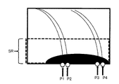
図5は、開始領域においてレールが消失する例を説明するための概略図である。
図5に示されているように、カメラ設置位置によって、開始領域SRにおいて、開始領域レール開始点指定部134で指定した開始点P1~P4が、車体又は影等の障害物で隠れる場合がある。
このような場合に、開始領域レール消失判断部136は、開始領域SRの仮レール部分が消失したと判断する。
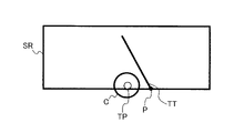
まず、開始領域レール消失判断部136は、四つの開始点P1~P4から順番に、一つの開始点を対象開始点TPとして選択する。
そして、対象開始点TPに最も距離の近いレール候補である仮レール部分を、対象仮レール部分TTとする。
次に、開始領域レール消失判断部136は、対象開始点TPと、対象仮レール部分TTとの距離を、下記の(3)式で算出する。
距離=|(対象仮レール部分の最下端のx座標)-(対象開始点のx座標)| (3)
なお、ここでは、開始点と、対象仮レール部分の最下端との距離を、x座標だけを用いて簡略的に算出しているが、本実施の形態は、このような例に限定されない。例えば、x座標及びy座標を用いて、2点間の距離が算出されてもよい。
これは、例えば、図6に示されているように、対象開始点TPを中心として、閾値を示す円Cの内部に、対象仮レール部分TTの最下端が存在しない場合には、そのような対象仮レール部分は、レール部分とはならないことを示している。
条件1:レール部分が一つ以下、言い換えると、レール部分の数が、0又は1であること。
条件2:レール部分が二つの場合には、レール部分の最下端のx座標の間の距離が、予め定められた閾値(第三の閾値)未満であること。
ここで、条件2の閾値(第三の閾値)は、レール軌間に基づいて、左右の二本のレールが検出されているか否かを判断できる値とすればよい。例えば、レール軌間又はレール軌間よりも予め定められた長さだけ短い値を閾値とすればよい。
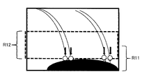
例えば、開始領域レール開始点再指定部137は、レール候補検出領域R11を開始領域SRに指定した場合に、レール消失と判断されたときには、次のレール候補検出領域R12を開始領域に指定する。
そして、開始領域レール開始点再指定部137は、指定した開始領域において、開始領域レール開始点指定部134と同様に、四つの開始点を指定する。
そして、開始領域レール選定部135は、複数の修正レール候補の内、修正開始点と最下端が最も近い修正レール候補をレール部分として選定する。ここで選定されるレール部分を仮修正レール部分ともいう。
また、開始領域レール消失判断部136は、仮修正レール部分の最下端と、修正開始点との間の距離が第一の閾値未満の場合に、その仮修正レール部分をレール部分として確定する。ここで確定されるレール部分を修正レール部分ともいう。
さらに、開始領域レール消失判断部136は、修正レール部分により二本のレールの両方の部分が検出されたか否かを判断する。
なお、開始領域でレール部分が確定された場合、レール候補検出部133は、開始領域又は修正開始領域を前領域とし、その前領域の一つ上のレール候補検出領域を次領域とする。そして、レール候補検出部133は、次領域において二本のレールのエッジの候補となる複数の線を複数のレール候補として検出する。ここで検出されるレール候補を次レール候補ともいう。
さらに、レール候補検出部133は、次領域でレール部分が確定した場合に、その次領域を前領域とするとともに、その次領域の一つ上のレール候補検出領域、言い換えると、その次領域と重複し、レール部分の確定が行われていないレール候補検出領域を、次領域とする。そして、レール候補検出部133は、次領域において二本のレールのエッジの候補となる複数の線を複数のレール候補として検出する。
例えば、次領域レール選定部138は、次領域の下辺と、レール部分又は修正レール部分との交点をレールの開始点として指定する。ここで指定された開始点を次開始点ともいう。
そして、次領域レール選定部138は、複数の次レール候補の内、レール部分又は修正レール部分との傾きの差が第二の閾値未満の次レール候補を選択次レール候補とする。
さらに、次領域レール選定部138は、選択次レール候補の内、次開始点と最下端が最も近い選択次レール候補を仮次レール部分として選定する。
例えば、次領域レール選定部138は、下記の(4)式のようにして算出される、前領域のレール部分に対応する直線と、レール候補に対応する直線との傾きの差である傾き差を、閾値と比較することで、レール候補を絞り込む。
傾き差=|(前領域のレール部分の傾き)-(次領域でのレール候補の傾き)| (4)
図8において、符号DTは、前領域において確定されたレール部分を示している。符号CT1及びCT2は、次領域において検出されているレール候補を示している。
図8においては、レール部分DTに対して、レール候補CT1及びレール候補CT2は、その傾き差が閾値以上であるため、選択レール候補又は選択次レール候補から除外される。この時の閾値は、レールのカーブの最大曲率(半径R:160m)から算出されてもよい。
図9に示されているように、前領域RTで確定されたレール部分DTと、次領域NRの最下端との交点Pが、開始点として特定される。
そして、次領域レール消失判断部139は、次レール部分により二本のレールの両方の部分が検出されたか否かを判断する。
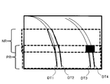
図10は、次領域のレールが消失する例を説明するための概略図である。
図10に示されているように、前領域PRで確定されたレール部分DT1~DT4と、次領域NRの最下辺との交点を開始点とする場合、開始点が影又はレール周辺の電気設備等の障害物で隠れる場合がある。消失条件は、例えば、開始領域レール消失判断部136と同様に、開始点に対して予め定められた閾値の範囲内を仮レール部分が通るか否かを、距離差から判断すればよい。
そして、次領域レール開始点再指定部140は、修正次領域の下辺と、レール部分又は修正レール部分との交点を開始点として指定する。ここで指定される開始点を修正次開始点ともいう。
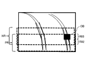
図11は、次領域と、前領域との間の重複領域を増やす処理を説明するための概略図である。
図11に示されているように、前領域PRに対して、一つの分割領域分(図11では、分割領域R02)、次領域NRが前領域PR側にずらされている。これにより、前領域PRと、次領域NRと重複領域に障害物OBがあったとしても、その障害物OBを避けて、次領域の開始点を指定することができる。
また、次領域レール選定部138は、複数の修正次レール候補の内、レール部分又は修正レール部分との傾きの差が第二の閾値未満の修正次レール候補を選択レール候補として選択する。ここで選択される選択レール候補を選択修正次レール候補ともいう。
さらに、次領域レール選定部138は、選択修正次レール候補の内、修正次開始点と最下端が最も近い選択修正次レール候補を仮レール部分として選定する。ここで選定される仮レール部分を仮修正次レール部分ともいう。
そして、次領域レール消失判断部139は、仮修正次レール部分の最下端と、修正次開始点との間の距離が第一の閾値未満の場合に、仮修正次レール部分をレール部分として確定する。ここで確定されるレール部分を修正次レール部分ともいう。
次領域レール消失判断部139は、修正次レール部分により二本のレールの両方の部分が検出されたか否かを判断する。
レール検出結果出力部142は、レール検出結果を表示装置102に出力する。
レール検出装置110は、CPU(Central Processing Unit)等のプロセッサ151と、メモリ152と、HDD(Hard Disc Drive)又はSSD(Solid State Drive)等の補助記憶装置153と、インターフェース(以下、I/Fという)154と、I/F155とを備えるコンピュータ150により実現することができる。
レール検出結果出力部142は、I/F155により実現することができる。I/F155は、例えば、表示装置102との間でデータをやりとりするインターフェースである。
なお、記憶部120は、補助記憶装置153により実現することができる。
動画像が入力される場合は、以下処理が繰り返し行われる。
次に、レール検出領域指定部131は、入力された画像においてレール検出領域を指定する(S11)。
レール候補検出部133は、生成されたレール候補検出領域において、レール候補を検出する(S13)。
開始領域レール選定部135は、指定された開始点に最も近いレール候補を、開始領域の仮レール部分として選定する(S15)。
次に、次領域レール消失判断部139は、次領域のレール条件を満たす仮レール部分を特定し、仮レール部分に基づいて、次領域においてレールが消失したか否かを判断する(S21)。レールが消失した場合(S21でYes)には、処理はステップS22に進み、レールが消失していない場合(S21でNo)には、処理はステップS24に進む。
開始領域レール選定部135は、開始領域において、開始領域レール開始点指定部134で指定された開始領域の開始点を特定する(S30)。
次に、開始領域レール選定部135は、開始領域の開始点と、開始領域におけるレール候補とを比較する(S31)。
まず、開始領域レール消失判断部136は、開始領域レール選定部135で選定された仮レール部分を開始領域において特定する(S40)。
一方、ステップS44では、開始領域レール消失判断部136は、開始領域においてレールが消失していないと判断する。
まず、開始領域レール開始点再指定部137は、開始領域を、一つ上のレール候補検出領域にずらし、ずらされた開始領域において、開始点を新たに指定する(S50)。
次に、レール候補検出部133は、開始領域においてレール候補を検出する(S51)。
次領域レール選定部138は、前領域で確定されたレール部分を特定する(S60)。
次に、次領域レール選定部138は、前領域で確定されたレール部分の傾きと、次領域のレール候補の傾きとを比較する(S61)。
まず、次領域レール消失判断部139は、次領域レール選定部138で選定された仮レール部分を次領域において特定する(S70)。
一方、ステップS74では、次領域レール消失判断部139は、次領域においてレールが消失していないと判断する。
まず、次領域レール開始点再指定部140は、次領域を、一つ下の分割領域を含むようにずらし、ずらされた次領域において、開始点を新たに指定する(S81)。
次に、レール候補検出部133は、次領域においてレール候補を検出する(S82)。
次領域レール選定部138は、前領域で確定されたレール部分の傾きと、次領域のレール候補の傾きとの傾き差が、予め定められた閾値以上のレール候補を、選択レール候補から除外する(S84)。
Claims (8)
- 二本のレールを含む画像から、前記二本のレールが含まれている領域をレール検出領域として指定するレール検出領域指定部と、
前記レール検出領域を上下方向において分割し、隣接する二つが重複するように複数のレール候補検出領域を生成するレール検出領域分割部と、
前記複数のレール候補検出領域の内、最も下のレール候補検出領域を開始領域に設定し、前記開始領域の下辺の予め定められた位置の点を前記二本のレールの開始点として指定する開始領域レール開始点指定部と、
前記開始領域において前記二本のレールのエッジの候補となる複数の線を複数のレール候補として検出するレール候補検出部と、
前記複数のレール候補の内、前記開始点と最下端が最も近いレール候補を仮レール部分として選定する開始領域レール選定部と、
前記仮レール部分の最下端と、前記開始点との間の距離が第一の閾値未満の場合に、前記仮レール部分をレール部分として確定し、前記レール部分により前記二本のレールの両方の部分が検出されたか否かを判断する開始領域レール消失判断部と、
前記レール部分により前記二本のレールの両方の部分が検出されていない場合に、前記開始領域を上方にずらすことで、修正開始領域を設定し、前記修正開始領域の下辺の予め定められた位置の点を前記二本のレールの開始点である修正開始点として指定する開始領域レール開始点再指定部と、を備え、
前記レール候補検出部は、前記修正開始領域において、前記二本のレールのエッジの候補となる複数の線を複数の修正レール候補として検出し、
前記開始領域レール選定部は、前記複数の修正レール候補の内、前記修正開始点と最下端が最も近い修正レール候補を仮修正レール部分として選定し、
前記開始領域レール消失判断部は、前記仮修正レール部分の最下端と、前記修正開始点との間の距離が前記第一の閾値未満の場合に、前記仮修正レール部分を修正レール部分として確定し、前記修正レール部分により前記二本のレールの両方の部分が検出されたか否かを判断すること
を特徴とするレール検出装置。 - 前記開始領域レール開始点再指定部は、前記複数のレール候補検出領域の内、前記開始領域の一つ上のレール候補検出領域を前記修正開始領域として設定すること
を特徴とする請求項1に記載のレール検出装置。 - 前記レール候補検出部は、前記レール部分又は前記修正レール部分により、前記二本のレールが検出された場合に、前記開始領域又は前記修正開始領域を前領域とし、前記複数のレール候補検出領域の内、前記前領域の一つ上のレール候補検出領域を次領域として、前記次領域において前記二本のレールのエッジの候補となる複数の線を複数の次レール候補として検出し、
前記次領域の下辺と、前記レール部分又は前記修正レール部分との交点を次開始点として指定し、前記複数の次レール候補の内、前記レール部分又は前記修正レール部分との傾きの差が第二の閾値未満の次レール候補を選択次レール候補とし、前記選択次レール候補の内、前記次開始点と最下端が最も近い選択次レール候補を仮次レール部分として選定する次領域レール選定部と、
前記仮次レール部分の最下端と、前記次開始点との間の距離が前記第一の閾値未満の場合に、前記仮次レール部分をレール部分である次レール部分として確定し、前記次レール部分により前記二本のレールの両方の部分が検出されたか否かを判断する次領域レール消失判断部と、
前記次レール部分により前記二本のレールの両方の部分が検出されていない場合に、前記次領域を下方にずらすことで、修正次領域を設定し、前記修正次領域の下辺と、前記レール部分又は前記修正レール部分との交点を修正次開始点として指定する次領域レール開始点再指定部と、をさらに備え、
前記レール候補検出部は、前記修正次領域において前記二本のレールのエッジの候補となる複数の線を複数の修正次レール候補として検出し、
前記次領域レール選定部は、前記複数の修正次レール候補の内、前記レール部分又は前記修正レール部分との傾きの差が前記第二の閾値未満の修正次レール候補を選択修正次レール候補とし、前記選択修正次レール候補の内、前記修正次開始点と最下端が最も近い選択修正次レール候補を仮修正次レール部分として選定し、
次領域レール消失判断部は、前記仮修正次レール部分の最下端と、前記修正次開始点との間の距離が前記第一の閾値未満の場合に、前記仮修正次レール部分をレール部分である修正次レール部分として確定し、前記修正次レール部分により前記二本のレールの両方の部分が検出されたか否かを判断すること
を特徴とする請求項1又は2に記載のレール検出装置。 - 前記レール検出領域分割部は、前記レール検出領域を上下方向において複数の分割領域に分割し、前記複数の分割領域から、連続する三つ以上の分割領域を含み、隣接する二つのレール候補検出領域が、少なくとも一つの分割領域において重複するように前記複数のレール候補検出領域を生成することを特徴とする請求項3に記載のレール検出装置。
- 前記次領域レール開始点再指定部は、前記複数の分割領域の内、前記次領域の一つ下の分割領域が含まれるように前記修正次領域を設定すること
を特徴とする請求項4に記載のレール検出装置。 - 前記開始領域レール消失判断部は、
二本以上の前記レール部分が確定し、二本の前記レール部分の間隔が第三の閾値以上である場合に、前記レール部分により前記二本のレールの両方の部分が検出されたと判断し、
二本以上の前記修正レール部分が確定し、二本の前記修正レール部分の間隔が前記第三の閾値以上である場合に、前記修正レール部分により前記二本のレールの両方の部分が検出されたと判断すること
を特徴とする請求項1又は2に記載のレール検出装置。 - 前記次領域レール消失判断部は、
二本以上の前記次レール部分が確定し、二本の前記次レール部分の間隔が第三の閾値以上である場合に、前記次レール部分により前記二本のレールの両方の部分が検出されたと判断し、
二本以上の前記修正次レール部分が確定し、二本の前記修正次レール部分の間隔が前記第三の閾値以上である場合に、前記修正次レール部分により前記二本のレールの両方の部分が検出されたと判断すること
を特徴とする請求項3から5の何れか一項に記載のレール検出装置。 - 二本のレールを含む画像から、前記二本のレールが含まれている領域をレール検出領域として指定し、
前記レール検出領域を上下方向において分割し、隣接する二つが重複するように複数のレール候補検出領域を生成し、
前記複数のレール候補検出領域の内、最も下のレール候補検出領域を開始領域に設定し、前記開始領域の下辺の予め定められた位置の点を前記二本のレールの開始点として指定し、
前記開始領域において前記二本のレールのエッジの候補となる複数の線を複数のレール候補として検出し、
前記複数のレール候補の内、前記開始点と最下端が最も近いレール候補を仮レール部分として選定し、
前記仮レール部分の最下端と、前記開始点との間の距離が第一の閾値未満の場合に、前記仮レール部分をレール部分として確定し、前記レール部分により前記二本のレールの両方の部分が検出されたか否かを判断し、
前記レール部分により前記二本のレールの両方の部分が検出されていない場合に、前記開始領域を上方にずらすことで、修正開始領域を設定し、前記修正開始領域の下辺の予め定められた位置の点を前記二本のレールの開始点である修正開始点として指定し、
前記修正開始領域において、前記二本のレールのエッジの候補となる複数の線を複数の修正レール候補として検出し、
前記複数の修正レール候補の内、前記修正開始点と最下端が最も近い修正レール候補を仮修正レール部分として選定し、
前記仮修正レール部分の最下端と、前記修正開始点との間の距離が前記第一の閾値未満の場合に、前記仮修正レール部分を修正レール部分として確定し、前記修正レール部分により前記二本のレールの両方の部分が検出されたか否かを判断すること
を特徴とするレール検出方法。
Priority Applications (4)
| Application Number | Priority Date | Filing Date | Title |
|---|---|---|---|
| PCT/JP2020/045568 WO2022123641A1 (ja) | 2020-12-08 | 2020-12-08 | レール検出装置及びレール検出方法 |
| DE112020007667.9T DE112020007667T5 (de) | 2020-12-08 | 2020-12-08 | Schienenerfassungsvorrichtung und schienenerfassungsverfahren |
| JP2022567739A JP7209916B2 (ja) | 2020-12-08 | 2020-12-08 | レール検出装置及びレール検出方法 |
| US18/137,660 US12417612B2 (en) | 2020-12-08 | 2023-04-21 | Rail detecting device and rail detection method |
Applications Claiming Priority (1)
| Application Number | Priority Date | Filing Date | Title |
|---|---|---|---|
| PCT/JP2020/045568 WO2022123641A1 (ja) | 2020-12-08 | 2020-12-08 | レール検出装置及びレール検出方法 |
Related Child Applications (1)
| Application Number | Title | Priority Date | Filing Date |
|---|---|---|---|
| US18/137,660 Continuation US12417612B2 (en) | 2020-12-08 | 2023-04-21 | Rail detecting device and rail detection method |
Publications (1)
| Publication Number | Publication Date |
|---|---|
| WO2022123641A1 true WO2022123641A1 (ja) | 2022-06-16 |
Family
ID=81973339
Family Applications (1)
| Application Number | Title | Priority Date | Filing Date |
|---|---|---|---|
| PCT/JP2020/045568 Ceased WO2022123641A1 (ja) | 2020-12-08 | 2020-12-08 | レール検出装置及びレール検出方法 |
Country Status (4)
| Country | Link |
|---|---|
| US (1) | US12417612B2 (ja) |
| JP (1) | JP7209916B2 (ja) |
| DE (1) | DE112020007667T5 (ja) |
| WO (1) | WO2022123641A1 (ja) |
Citations (5)
| Publication number | Priority date | Publication date | Assignee | Title |
|---|---|---|---|---|
| JP2002008019A (ja) * | 2000-06-21 | 2002-01-11 | Fuji Heavy Ind Ltd | 軌道認識装置及び軌道認識装置を用いた鉄道車両 |
| JP2002175534A (ja) * | 2000-12-06 | 2002-06-21 | Sumitomo Electric Ind Ltd | 道路の白線検出方法 |
| JP2008158673A (ja) * | 2006-12-21 | 2008-07-10 | Toyota Motor Corp | 道路区画線認識装置 |
| US20150248837A1 (en) * | 2014-02-28 | 2015-09-03 | Core Logic, Inc. | System and Method for Warning Lane Departure |
| JP2019209734A (ja) * | 2018-05-31 | 2019-12-12 | 株式会社東芝 | 軌道識別装置 |
Family Cites Families (8)
| Publication number | Priority date | Publication date | Assignee | Title |
|---|---|---|---|---|
| IL117279A (en) | 1996-02-27 | 2000-01-31 | Israel Aircraft Ind Ltd | System for detecting obstacles on a railway track |
| US11767016B2 (en) * | 2002-06-04 | 2023-09-26 | Transportation Ip Holdings, Llc | Optical route examination system and method |
| FR3019508B1 (fr) * | 2014-04-08 | 2017-12-08 | Alstom Transp Tech | Procede de detection de rails sur lesquels circule un vehicule ferroviaire |
| JP6572411B2 (ja) | 2014-11-11 | 2019-09-11 | 株式会社明電舎 | レール検出装置 |
| US11021177B2 (en) | 2016-10-20 | 2021-06-01 | Rail Vision Ltd | System and method for object and obstacle detection and classification in collision avoidance of railway applications |
| JP6903477B2 (ja) | 2017-04-21 | 2021-07-14 | 株式会社東芝 | 軌道識別装置、およびプログラム |
| US10679505B2 (en) * | 2018-02-22 | 2020-06-09 | Alstom Transport Technologies | Automatic vehicle control apparatus able to determine track occupancy of a vehicle, and corresponding method for automatically controlling the vehicle |
| CN112508892B (zh) * | 2020-11-27 | 2024-10-18 | 中国铁路南宁局集团有限公司 | 基于机器视觉的铁路轨道面微小异物检测方法及系统 |
-
2020
- 2020-12-08 JP JP2022567739A patent/JP7209916B2/ja active Active
- 2020-12-08 DE DE112020007667.9T patent/DE112020007667T5/de active Pending
- 2020-12-08 WO PCT/JP2020/045568 patent/WO2022123641A1/ja not_active Ceased
-
2023
- 2023-04-21 US US18/137,660 patent/US12417612B2/en active Active
Patent Citations (5)
| Publication number | Priority date | Publication date | Assignee | Title |
|---|---|---|---|---|
| JP2002008019A (ja) * | 2000-06-21 | 2002-01-11 | Fuji Heavy Ind Ltd | 軌道認識装置及び軌道認識装置を用いた鉄道車両 |
| JP2002175534A (ja) * | 2000-12-06 | 2002-06-21 | Sumitomo Electric Ind Ltd | 道路の白線検出方法 |
| JP2008158673A (ja) * | 2006-12-21 | 2008-07-10 | Toyota Motor Corp | 道路区画線認識装置 |
| US20150248837A1 (en) * | 2014-02-28 | 2015-09-03 | Core Logic, Inc. | System and Method for Warning Lane Departure |
| JP2019209734A (ja) * | 2018-05-31 | 2019-12-12 | 株式会社東芝 | 軌道識別装置 |
Also Published As
| Publication number | Publication date |
|---|---|
| DE112020007667T5 (de) | 2023-09-07 |
| JP7209916B2 (ja) | 2023-01-20 |
| US12417612B2 (en) | 2025-09-16 |
| JPWO2022123641A1 (ja) | 2022-06-16 |
| US20230260246A1 (en) | 2023-08-17 |
Similar Documents
| Publication | Publication Date | Title |
|---|---|---|
| US11928805B2 (en) | Information processing apparatus, information processing method, and storage medium for defect inspection and detection | |
| JP5699633B2 (ja) | 画像処理装置、画素補間方法およびプログラム | |
| JP5404263B2 (ja) | 視差算出方法、および視差算出装置 | |
| US11733174B2 (en) | Information processing apparatus, information processing method, and storage medium | |
| JP6307873B2 (ja) | 対象線検出装置、方法、及びプログラム | |
| KR102225620B1 (ko) | 카메라 모델링 시스템 | |
| JP4296617B2 (ja) | 画像処理装置および画像処理方法、並びに記録媒体 | |
| KR20140056790A (ko) | 영상 인식 장치 및 그 방법 | |
| US20230260159A1 (en) | Information processing apparatus, information processing method, and non-transitory computer readable medium | |
| WO2022123641A1 (ja) | レール検出装置及びレール検出方法 | |
| US20240013420A1 (en) | Image processing apparatus, image processing method, and storage medium | |
| JP5114290B2 (ja) | 信号処理装置 | |
| JP4018950B2 (ja) | ステレオカメラの位置ずれ検査装置および位置ずれ検査方法 | |
| JP4107273B2 (ja) | 移動体検出装置 | |
| JP4468019B2 (ja) | 画像処理装置 | |
| JP7263983B2 (ja) | 撮影漏れ検出装置、及び、撮影漏れ検出方法 | |
| JP5703777B2 (ja) | 画像処理装置、画素補間方法およびプログラム | |
| JP4351090B2 (ja) | 画像処理装置および画像処理方法 | |
| JP5579297B2 (ja) | 視差算出方法、および視差算出装置 | |
| JP6464706B2 (ja) | 物体検出方法、物体検出プログラムおよび物体検出装置 | |
| CN115937235B (zh) | 边缘位置检测方法及装置 | |
| JP2021022208A (ja) | 画像処理システム | |
| JP2007206963A (ja) | 画像処理装置及び画像処理方法及びプログラム及び記憶媒体 | |
| JP2007141167A (ja) | 車線検出装置、車線検出方法、及び車線検出プログラム | |
| JP7066580B2 (ja) | 画像処理装置 |
Legal Events
| Date | Code | Title | Description |
|---|---|---|---|
| 121 | Ep: the epo has been informed by wipo that ep was designated in this application |
Ref document number: 20965027 Country of ref document: EP Kind code of ref document: A1 |
|
| ENP | Entry into the national phase |
Ref document number: 2022567739 Country of ref document: JP Kind code of ref document: A |
|
| WWE | Wipo information: entry into national phase |
Ref document number: 202347038423 Country of ref document: IN |
|
| 122 | Ep: pct application non-entry in european phase |
Ref document number: 20965027 Country of ref document: EP Kind code of ref document: A1 |