WO2022123622A1 - 音声信号処理装置及び方法 - Google Patents
音声信号処理装置及び方法 Download PDFInfo
- Publication number
- WO2022123622A1 WO2022123622A1 PCT/JP2020/045443 JP2020045443W WO2022123622A1 WO 2022123622 A1 WO2022123622 A1 WO 2022123622A1 JP 2020045443 W JP2020045443 W JP 2020045443W WO 2022123622 A1 WO2022123622 A1 WO 2022123622A1
- Authority
- WO
- WIPO (PCT)
- Prior art keywords
- sampling frequency
- acoustic signal
- functional block
- output
- signal processing
- Prior art date
- Legal status (The legal status is an assumption and is not a legal conclusion. Google has not performed a legal analysis and makes no representation as to the accuracy of the status listed.)
- Ceased
Links
Images



Classifications
-
- G—PHYSICS
- G10—MUSICAL INSTRUMENTS; ACOUSTICS
- G10L—SPEECH ANALYSIS TECHNIQUES OR SPEECH SYNTHESIS; SPEECH RECOGNITION; SPEECH OR VOICE PROCESSING TECHNIQUES; SPEECH OR AUDIO CODING OR DECODING
- G10L21/00—Speech or voice signal processing techniques to produce another audible or non-audible signal, e.g. visual or tactile, in order to modify its quality or its intelligibility
- G10L21/003—Changing voice quality, e.g. pitch or formants
-
- G—PHYSICS
- G10—MUSICAL INSTRUMENTS; ACOUSTICS
- G10L—SPEECH ANALYSIS TECHNIQUES OR SPEECH SYNTHESIS; SPEECH RECOGNITION; SPEECH OR VOICE PROCESSING TECHNIQUES; SPEECH OR AUDIO CODING OR DECODING
- G10L21/00—Speech or voice signal processing techniques to produce another audible or non-audible signal, e.g. visual or tactile, in order to modify its quality or its intelligibility
- G10L21/02—Speech enhancement, e.g. noise reduction or echo cancellation
- G10L21/0316—Speech enhancement, e.g. noise reduction or echo cancellation by changing the amplitude
- G10L21/0324—Details of processing therefor
-
- G—PHYSICS
- G10—MUSICAL INSTRUMENTS; ACOUSTICS
- G10L—SPEECH ANALYSIS TECHNIQUES OR SPEECH SYNTHESIS; SPEECH RECOGNITION; SPEECH OR VOICE PROCESSING TECHNIQUES; SPEECH OR AUDIO CODING OR DECODING
- G10L21/00—Speech or voice signal processing techniques to produce another audible or non-audible signal, e.g. visual or tactile, in order to modify its quality or its intelligibility
- G10L21/02—Speech enhancement, e.g. noise reduction or echo cancellation
- G10L21/0208—Noise filtering
- G10L2021/02082—Noise filtering the noise being echo, reverberation of the speech
-
- G—PHYSICS
- G10—MUSICAL INSTRUMENTS; ACOUSTICS
- G10L—SPEECH ANALYSIS TECHNIQUES OR SPEECH SYNTHESIS; SPEECH RECOGNITION; SPEECH OR VOICE PROCESSING TECHNIQUES; SPEECH OR AUDIO CODING OR DECODING
- G10L21/00—Speech or voice signal processing techniques to produce another audible or non-audible signal, e.g. visual or tactile, in order to modify its quality or its intelligibility
- G10L21/02—Speech enhancement, e.g. noise reduction or echo cancellation
- G10L21/0208—Noise filtering
Definitions
- the present invention relates to an audio signal processing device and a method.
- each functional block is installed to realize various functions such as voice recognition, hands-free calling, so-called "In-Car Communication".
- Signal processing in each functional block is performed on the acoustic signal in digital signal format, and each functional block defines an internal sampling frequency for signal processing.
- the delay of the acoustic signal becomes large. This is because a sound buffer is indispensable before and after the sampling frequency converter of the software, and a delay occurs by the time of passing through the sound buffer. An increase in the delay time leads to a deterioration in the performance of each function. Depending on the degree of increase in delay time, the required specifications cannot be met, and the product itself including the audio signal processing device cannot be put on the market.
- an object of the present invention is to provide an audio signal processing device and a method that contributes to the suppression of signal delay time.
- the voice signal processing device includes a sampling frequency converter that converts a sampling frequency of an input voice signal, a plurality of functional blocks that perform signal processing on the voice signal whose sampling frequency has been converted, and the above-mentioned.
- the sampling frequency converter includes a function selection unit for selecting one of a plurality of functional blocks, and the sampling frequency converter determines the sampling frequency of the input audio signal according to the internal sampling frequency used in the selected functional block. It is a configuration to be converted (first configuration).
- the sampling frequency converter converts the sampling frequency of the input audio signal to the same sampling frequency as the internal sampling frequency used in the selected functional block. (Second configuration) may be used.
- the voice signal processing method includes a sampling frequency conversion step for converting a sampling frequency of an input voice signal, a plurality of functional steps for performing signal processing on the voice signal whose sampling frequency has been converted, and the above-mentioned.
- the sampling frequency conversion step comprises a function selection step for selecting one of a plurality of function steps, and the sampling frequency conversion step sets the sampling frequency of the input audio signal according to the internal sampling frequency used in the selected function step. It is a configuration to be converted (third configuration).
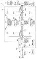
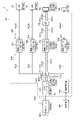
- FIG. 1 It is a figure which shows the state of the inside of the vehicle which concerns on embodiment of this invention. It is an internal block diagram of the head unit which focused on the function realized in cooperation with a microphone which concerns on embodiment of this invention. It is an operation flowchart of a head unit which focused on the function realized in cooperation with a microphone which concerns on embodiment of this invention. Reference It is an internal block diagram of a head unit. It is a deformation internal block diagram about the head unit of FIG.
- FIG. 1 schematically shows the inside of the vehicle CR according to the embodiment of the present invention.
- the inside of the vehicle or the inside of the vehicle refers to the interior of the vehicle CR.
- a vehicle autonomous or the like
- the vehicle CR may be any kind of vehicle.
- Multiple occupants can board the vehicle CR.
- Seats ST1 to ST3 are provided in the vehicle CR.
- the seat ST1 is a driver's seat on which the driver of the vehicle CR sits.
- the occupant PS1 represents the driver of the vehicle CR. Therefore, the occupant PS1 may be referred to as the driver PS1.
- occupants other than the driver may be referred to as passengers.
- the direction from the driver's seat ST1 toward the steering wheel STR of the vehicle CR is defined as "forward", and the direction from the steering wheel STR of the vehicle CR toward the driver's seat ST1 is defined as “rear”.
- the terms left and right refer to the left and right as seen from the driver PS1 who sits facing forward in the driver's seat ST1 unless otherwise specified.
- Seat ST2 (passenger seat) is installed on the left side of seat ST1, and seat ST3 (hereinafter, may be referred to as rear seat ST3) is provided behind seats ST1 and ST2.
- Crew members that is, passengers
- the seat ST3 is a wide seat in which a plurality of occupants can sit.
- the occupants PS2 and PS3 are passengers sitting in the rear seat ST3.
- the head unit 1 is installed in the passenger compartment of the vehicle CR.
- the head unit 1 is installed in front of the driver's seat ST1 so that the driver PS1 can easily see the display unit provided on the head unit 1.
- an in-vehicle speaker SP is installed at an appropriate position in the vehicle interior of the vehicle CR.
- the head unit 1 and the in-vehicle speaker SP are wirelessly or wiredly connected, and a signal can be transmitted from the head unit 1 to the in-vehicle speaker SP.
- a signal can be transmitted from the head unit 1 to the in-vehicle speaker SP.
- FIG. 1 Although only one in-vehicle speaker SP is shown in FIG. 1, a plurality of in-vehicle speaker SPs may be installed in the vehicle interior, or an in-vehicle speaker SP may be assigned to each occupant.
- the in-vehicle speaker SP is a speaker for realizing so-called "In-Car Communication".
- the code "TM" represents a terminal device possessed by the driver PS1.
- the terminal device TM is, for example, an information terminal such as a mobile phone (including one classified as a smart phone) or a tablet.
- the terminal device TM has a telephone function. That is, in the telephone function, the terminal device TM and the other party device (not shown) are connected through a predetermined line, and the driver PS1 who is the user of the terminal device TM and the user of the other party device make a call through the terminal device TM and the other party device. can.
- the head unit 1 is wirelessly connected to the terminal device TM in accordance with a short-range wireless communication standard such as Bluetooth (registered trademark), and the driver PS1 can make a so-called hands-free call by cooperating with the head unit 1 and the terminal device TM. It is possible.
- a short-range wireless communication standard such as Bluetooth (registered trademark)
- the head unit 1 includes a microphone, a display unit, a CPU (Central Processing Unit), a memory, a DSP (Digital Signal Processor), an operation unit, a communication processing unit, and the like, and can realize many functions.
- the functions realized by the head unit 1 include a navigation function that supports the movement of the vehicle CR to the destination, a driving support function that supports the driving operation of the vehicle CR, and a moving image reproduction function that reproduces an arbitrary moving image.
- An audio function for reproducing an acoustic signal such as music is included, but in the following, attention will be paid to a function realized in cooperation with a microphone, and a configuration and an operation related to the attention function will be described.
- FIG. 2 shows the configuration related to the attention function among the configurations of the head unit 1.
- the head unit 1 includes a front end 10, a CPU (Central Processing Unit) 20, a voice recognition processing unit 30, a voice recognition processing unit 40, and an operation unit 50 as components related to the above-mentioned attention function.
- CPU Central Processing Unit
- the microphone MIC is a microphone installed in the passenger compartment of the vehicle CR, and is installed at a position where it is easy to collect the utterance content of the driver PS1 (for example, a predetermined position on the steering wheel STR).
- the microphone MIC may be understood to be included in the components of the head unit 1 or may be understood to be an external device connected to the head unit 1.
- the microphone MIC picks up its own ambient sound, converts the picked up sound into an acoustic signal, and outputs it.
- the front end 10 generates a digital acoustic signal AS0 by sampling an analog acoustic signal output from the microphone MIC at a predetermined sampling frequency f0 (that is, the analog acoustic signal from the microphone MIC is a digital acoustic signal). Convert to AS0).
- the front end 10 is configured to include, for example, a DSP (Digital Signal Processor) for an acoustic signal, and necessary signal processing may be performed in the process of generating the acoustic signal AS0.
- the sampling frequency f0 is assumed to be 48 kHz (kilohertz) here. The sampling frequency may be read as the sampling rate.
- the CPU 20 includes an SRC 210, a sound buffer 220, a functional block group 230, a sound buffer group 240, and a function selection unit 250.
- the functional block group 230 is composed of two or more arbitrary number of functional blocks
- the sound buffer group 240 is composed of sound buffers for the number of functional blocks provided in the functional block group 230.
- a total of four functional blocks 231 to 234 are provided in the functional block group 230
- a total of four sound buffers 241 to 244 associated with the functional blocks 231 to 234 on a one-to-one basis are sound buffer groups. It is provided in 240.
- Each sound buffer is configured by a data memory (not shown) provided in the CPU 20.
- the CPU 20 is equipped with a hardware function and a software function.
- the hardware function is realized by a single piece of hardware such as a semiconductor integrated circuit formed in the CPU 20.
- the software function is realized by executing a program stored in a predetermined program memory (not shown) in a calculation block.
- the program memory is built in the CPU 20 or externally connected to the CPU 20. Since the arithmetic block itself is composed of hardware (semiconductor integrated circuit, etc.) in the CPU 20, the software function is strictly realized by a combination of hardware and software (program).
- the SRC210 is configured by the hardware function. That is, the SRC210 is realized by a single piece of hardware such as a semiconductor integrated circuit.
- the software function includes a sound buffer 220, a functional block group 230, a sound buffer group 240, and a function selection unit 250. Each component of the CPU 20 will be described.
- the acoustic signal AS0 from the front end 10 is input to the SRC210.
- the SRC210 generates an output acoustic signal having an output sampling frequency f OUT from an input acoustic signal having an input sampling frequency f IN .
- the input sampling frequency f IN is the sampling frequency f0 of the acoustic signal AS0.
- the input acoustic signal of the SRC210 consists of a sequence of digital data discretized at intervals of the reciprocal of the input sampling frequency f IN .
- the SRC210 is a hardware sampling frequency converter that converts the sampling frequency of the input acoustic signal AS0 into the output sampling frequency f OUT .
- the acoustic signal having the output sampling frequency f OUT obtained by this conversion is the output acoustic signal of the SRC 210.
- the output acoustic signal of the SRC210 consists of a sequence of digital data discretized at intervals of the reciprocal of the output sampling frequency f OUT .
- all the acoustic signals handled in the subsequent stage after the SRC210 are digital acoustic signals (acoustic signals expressed in the digital signal format).
- the SRC 210 is configured so that any one of a plurality of output candidate frequencies can be selectively set to the output sampling frequency f OUT .
- the number of output candidate frequencies is arbitrary as long as it is 2 or more, but here, it is assumed that a plurality of output candidate frequencies are three frequencies f1, f2, and f3.
- the frequencies f1, f2 and f3 are three different frequencies, the frequency f1 multiplied by the first integer, the frequency f2 multiplied by the second integer, and the frequency f3 multiplied by the third integer. Each of these values coincides with the input sampling frequency f IN (that is, frequency f0).
- the SRC210 can generate an output acoustic signal having an output sampling frequency f OUT by thinning out a part of the digital signal indicating the input acoustic signal AS0 according to the ratio between the frequencies f IN and f OUT .
- the state in which the frequency f1 is set as the output sampling frequency f OUT is referred to as a first frequency setting state, and the output acoustic signal of the SRC210 in the first frequency setting state is referred to as an acoustic signal AS1. Therefore, the sampling frequency of the acoustic signal AS1 coincides with the frequency f1. That is, the acoustic signal AS1 consists of a sequence of digital data discretized at intervals of the reciprocal of the frequency f1.
- the state in which the frequency f2 is set as the output sampling frequency f OUT is referred to as a second frequency setting state, and the output acoustic signal of the SRC210 in the second frequency setting state is referred to as an acoustic signal AS2.
- the sampling frequency of the acoustic signal AS2 coincides with the frequency f2. That is, the acoustic signal AS2 consists of a sequence of digital data discretized at intervals of the reciprocal of the frequency f2.
- the state in which the frequency f3 is set as the output sampling frequency f OUT is referred to as a third frequency setting state, and the output acoustic signal of the SRC210 in the third frequency setting state is referred to as an acoustic signal AS3. Therefore, the sampling frequency of the acoustic signal AS3 coincides with the frequency f3. That is, the acoustic signal AS3 consists of a sequence of digital data discretized at intervals of the reciprocal of the frequency f3. Under the control of the function selection unit 250, the output sampling frequency f OUT is switched and set to any of the frequencies f1 to f3.
- the sound buffer 220 stores digital data (digital values) of the output acoustic signal of the SRC 210 for a predetermined number of NUM 220 minutes.
- the predetermined number may be read as a predetermined amount of data.
- the digital data of the output acoustic signal of the SRC210 represents the individual digital values discretized in time series that constitute the output acoustic signal of the SRC210. Therefore, for example, in the first frequency setting state in which the acoustic signal AS1 is output from the SRC210, the digital data of the acoustic signal AS1 for "NUM 220 / f1" seconds can be stored in the sound buffer 220, and the acoustic signal AS2 is output from the SRC210. In the second frequency setting state, the digital data of the acoustic signal AS2 for "NUM 220 / f2" seconds can be stored in the sound buffer 220.
- new digital data new digital data in the output acoustic signal of SRC210
- the digital data of the output acoustic signal of SRC210 is stored in the sound buffer 220 for a predetermined number of NUM 220 minutes
- a sound is produced.
- the new digital data may be overwritten and recorded with respect to the digital data at the oldest time. That is, the digital data at the oldest time may be erased from the sound buffer 220, and the new digital data may be stored in the sound buffer 220 instead.
- Each functional block included in the functional block group 230 receives digital data of the acoustic signal stored in the sound buffer 220 as input data, and performs predetermined signal processing on the software for the acoustic signal represented by the input data. Then, each functional block included in the functional block group 230 outputs the digital data of the acoustic signal obtained by performing the signal processing to the sound buffer corresponding to itself.
- the sound buffers corresponding to the functional blocks 231 to 234 are sound buffers 241 to 244, respectively.
- Each functional block has a predetermined internal sampling frequency, and each functional block receives digital data (digital data of acoustic signals) with a sampling frequency that matches its own internal sampling frequency as input data. Further, the function selection unit 250 selects any one of the functional blocks 231 to 234 as the operation target block, and only the functional block selected as the operation target block among the functional blocks 231 to 234 is significant. Operate.
- the internal sampling frequency of the functional block 231 is frequency f2. Therefore, the functional block 231 operates significantly only in the second frequency setting state in which the acoustic signal AS2 having the sampling frequency f2 is output from the SRC210.
- the output sampling frequency f OUT of the SRC 210 is set to the frequency f2 under the control of the function selection unit 250.
- the functional block 231 receives the digital data of the acoustic signal AS2 stored in the sound buffer 220 as input data, and processes the input data with a predetermined first signal. To execute.
- the output acoustic signal of the functional block 231 that is, the acoustic signal obtained by performing the first signal processing on the acoustic signal AS2 (that is, the acoustic signal AS2 after the first signal processing) is referred to as an acoustic signal AS2a.
- the sampling frequency of the acoustic signal AS2a also matches the internal sampling frequency of the functional block 231 (that is, the frequency f2).
- the functional block 231 outputs the digital data of the acoustic signal AS2a to the sound buffer 241 corresponding to itself.
- the sound buffer 241 stores the digital data (digital value) of the output acoustic signal AS2a of the functional block 231 for a predetermined number of NUM 241 minutes.
- the predetermined number may be read as a predetermined amount of data.
- the output acoustic signal AS2a of the functional block 231 is composed of a sequence of digital data discretized at intervals of the reciprocals of the internal sampling frequency of the functional block 231.
- the digital data of the output acoustic signal AS2a represents individual digital values discretized in time series that constitute the output acoustic signal AS2a.
- the digital data of the acoustic signal AS2a for "NUM 241 / f2" seconds can be stored in the sound buffer 241.
- the functional block 231 is digital data of the acoustic signal AS2 input from the sound buffer 220, and is digital data of the acoustic signal AS2a by performing the first signal processing on the digital data for a certain amount of data.
- a certain amount of digital data is output to the sound buffer 241.
- the digital data of the acoustic signal AS2a and a certain amount of digital data are sequentially updated to the latest ones and stored in the sound buffer 241.
- the internal sampling frequency of the functional block 232 is frequency f2. Therefore, the functional block 232 operates significantly only in the second frequency setting state in which the acoustic signal AS2 having the sampling frequency f2 is output from the SRC210.
- the output sampling frequency f OUT of the SRC 210 is set to the frequency f2 under the control of the function selection unit 250.
- the functional block 232 receives the digital data of the acoustic signal AS2 stored in the sound buffer 220 as input data, and processes the input data with a predetermined second signal. To execute.
- the output acoustic signal of the functional block 232 that is, the acoustic signal obtained by performing the second signal processing on the acoustic signal AS2 (that is, the acoustic signal AS2 after the second signal processing) is referred to as an acoustic signal AS2b.
- the sampling frequency of the acoustic signal AS2b also coincides with the internal sampling frequency of the functional block 232 (that is, the frequency f2).
- the functional block 232 outputs the digital data of the acoustic signal AS2b to the sound buffer 242 corresponding to itself.
- the sound buffer 242 stores the digital data (digital value) of the output acoustic signal AS2b of the functional block 232 for a predetermined number of NUM 242 minutes.
- the predetermined number may be read as a predetermined amount of data.
- the output acoustic signal AS2b of the functional block 232 is composed of a sequence of digital data discretized at intervals of the reciprocals of the internal sampling frequency of the functional block 232.
- the digital data of the output acoustic signal AS2b represents the individual digital values discretized in time series constituting the output acoustic signal AS2b.
- the functional block 232 is the digital data of the acoustic signal AS2 input from the sound buffer 220, and is the digital data of the acoustic signal AS2b by performing the second signal processing on the digital data for a certain amount of data.
- a certain amount of digital data is output to the sound buffer 242.
- the digital data of the acoustic signal AS2b and a certain amount of digital data are sequentially updated to the latest ones and stored in the sound buffer 242.
- a plurality of internal candidate frequencies are defined as candidates for the internal sampling frequency, and any one of the plurality of internal candidate frequencies is set as the internal sampling frequency of the functional block 233.
- the number of the plurality of internal candidate frequencies is arbitrary, but each internal candidate frequency matches any of the candidates for the output sampling frequency f OUT of the SRC 210 (that is, any of the above-mentioned plurality of output candidate frequencies).
- the plurality of internal candidate frequencies are three frequencies f1, f2, and f3.
- the functional block 233 itself may be the main body to determine its own internal sampling frequency, but here, it is considered that the internal sampling frequency of the functional block 233 is set under the control of the function selection unit 250.
- the function selection unit 250 also sets the internal sampling frequency of the function block 233, and in conjunction with this, the output sampling frequency f OUT of the SRC 210 is inside the function block 233.
- the output sampling frequency f OUT of the SRC210 is also set so as to match the sampling frequency.
- the output sampling frequency f OUT of the SRC 210 is also set to the frequency f1 and the functional block 233 is set.
- the output sampling frequency f OUT of the SRC210 is also set to the frequency f2.
- the functional block 233 When the functional block 233 is set as the operation target block, the functional block 233 receives digital data of an acoustic signal (AS1, AS2 or AS3) stored in the sound buffer 220 as input data, and receives the digital data with respect to the input data. Perform the predetermined third signal processing.
- the third signal processing is performed on the acoustic signal AS1.
- the acoustic signal that is, the acoustic signal AS1 after the third signal processing
- AS1c an acoustic signal AS1c.
- the third signal processing is performed on the acoustic signal AS2.
- the acoustic signal (that is, the acoustic signal AS2 after the third signal processing) obtained through the third signal processing with respect to the acoustic signal AS2 is referred to as an acoustic signal AS2c.
- the third signal processing is performed on the acoustic signal AS3.
- the acoustic signal obtained through the third signal processing with respect to the acoustic signal AS3 (that is, the acoustic signal AS3 after the third signal processing) is referred to as an acoustic signal AS3c.
- the sampling frequencies of the acoustic signals AS1c, AS2c, and AS3c coincide with the frequencies f1, f2, and f3, respectively.
- the functional block 233 outputs the digital data of the acoustic signal (AS1c, AS2c or AS3c) obtained through the third signal processing to the sound buffer 243 corresponding to itself.
- the sound buffer 243 stores digital data (digital values) of the output acoustic signals (AS1c, AS2c or AS3c) of the functional block 233 for a predetermined number of NUM 243 minutes.
- the predetermined number may be read as a predetermined amount of data.
- the output acoustic signal of the functional block 233 is composed of a sequence of digital data discretized at intervals of the reciprocal of the internal sampling frequency of the functional block 233.
- the digital data of the output acoustic signal of the functional block 233 represents the individual digital values discretized in time series constituting the output acoustic signal of the functional block 233.
- the functional block 233 is the digital data of the acoustic signals (AS1, AS2, AS3) input from the sound buffer 220, and is subjected to the third signal processing on the digital data corresponding to a certain amount of data, whereby the functional block 233 of the functional block 233 Output Sound signals (AS1c, AS2c, AS3c) digital data and a certain amount of digital data are output to the sound buffer 243.
- the digital data of the output acoustic signals (AS1c, AS2c, AS3c) of the functional block 233, and the digital data for a certain amount of data are sequentially updated to the latest ones and stored in the sound buffer 243.
- the internal sampling frequency of the functional block 234 is frequency f1. Therefore, the functional block 234 operates significantly only in the first frequency setting state in which the acoustic signal AS1 having the sampling frequency f1 is output from the SRC210.
- the output sampling frequency f OUT of the SRC 210 is set to the frequency f1 under the control of the function selection unit 250.
- the functional block 234 receives the digital data of the acoustic signal AS1 stored in the sound buffer 220 as input data, and processes the input data with a predetermined fourth signal. To execute.
- the output acoustic signal of the functional block 234, that is, the acoustic signal obtained by subjecting the acoustic signal AS1 to the fourth signal processing (that is, the acoustic signal AS1 after the fourth signal processing) is referred to as an acoustic signal AS1d.
- the sampling frequency of the acoustic signal AS1d also coincides with the internal sampling frequency of the functional block 234 (that is, the frequency f1).
- the functional block 234 outputs the digital data of the acoustic signal AS1d to the sound buffer 244 corresponding to itself.
- the sound buffer 244 stores the digital data (digital value) of the output acoustic signal AS1d of the functional block 234 for a predetermined number of NUM 244 minutes.
- the predetermined number may be read as a predetermined amount of data.
- the output acoustic signal AS1d of the functional block 234 is composed of a sequence of digital data discretized at intervals of the reciprocals of the internal sampling frequency of the functional block 234.
- the digital data of the output acoustic signal AS1d represents the individual digital values discretized in time series constituting the output acoustic signal AS1d.
- the functional block 234 is the digital data of the acoustic signal AS1 input from the sound buffer 220, and is the digital data of the acoustic signal AS1d by performing the fourth signal processing on the digital data for a certain amount of data.
- a certain amount of digital data is output to the sound buffer 244.
- the digital data of the acoustic signal AS1d and a certain amount of digital data are sequentially updated to the latest ones and stored in the sound buffer 244.
- the number of digital data (data amount) NUM 220 and NUM 241 to NUM 244 that can be stored in the sound buffers 220 and 241 to 244 are arbitrary, and they may or may not match.
- the first to fourth signal processes executed in the functional blocks 231 to 234 are different signal processes from each other. However, among the first to fourth signal processing, any two or more signal processing may be substantially the same signal processing.
- the first to fourth signal processing may be arbitrary signal processing required for the subsequent processing of the functional blocks 231 to 234.
- the first to fourth signal processings are the first ECNR processing, the second ECNR processing, the third ECNR processing, and the ICC processing, respectively.
- the first to third ECNR processes belong to the ECNR process, and the ECNR process includes an echo cancel process and a noise reduction process.
- the sound collection target of the microphone MIC is mainly the voice of the driver PS1's speech, and voice recognition or hands-free call is performed based on the sound collection result of the microphone MIC, or the driver PS1 is performed by "In-Car Communication".
- the content of the speech is output from the in-vehicle speaker SP.
- the sound output from the in-vehicle speaker SP or the speaker (not shown) provided in the head unit 1 also reaches the microphone MIC.
- These sounds function as noise for the spoken voice of the driver PS1, and are particularly called echoes.
- the echo cancellation process reduces the echo.
- noise reduction processing for reducing noise other than echo is also executed. Since the methods of echo cancellation processing and noise reduction processing themselves are known, detailed description of these processing contents will be omitted.
- the first ECNR process executed by the functional block 231 is an ECNR process designed suitable for the first speech recognition process executed by the speech recognition processing unit 30 in the subsequent stage, and is for a specific country (for example, for China).
- the second ECNR process executed by the functional block 232 is an ECNR process designed suitable for the second voice recognition process executed by the voice recognition processing unit 40 in the subsequent stage, and is for a country other than a specific country (for example,). ECNR processing for any country other than China).
- the third ECNR process executed by the functional block 233 is an ECNR process designed suitable for hands-free calling.
- the ICC processing executed by the functional block 234 is a signal processing designed to output the utterance voice of the driver PS1 from the in-vehicle speaker SP with good quality.
- outputting the utterance voice of the driver PS1 from the in-vehicle speaker SP is referred to as ICC voice output.
- the voice recognition processing unit 30 is based on the digital data stored in the sound buffer 241 (that is, based on the acoustic signal AS2a) when the functional block 231 is selected as the operation target block, and the speaker (here, the driver PS1) ),
- the first voice recognition process for recognizing the utterance content is executed.
- the utterance content of the speaker is converted into text data.
- the head unit 1 may perform response processing for understanding the intention of the speaker based on the text data obtained by the conversion and performing a necessary response.
- the response process may be included in the first speech recognition process.
- the response processing for example, information such as weather information, news, stores or tourist spots is provided to the speaker by voice response or display response according to the utterance content of the speaker (here, driver PS1). Further, for example, when the speaker makes an utterance instructing the setting of the destination, in the response processing, the destination in the navigation operation is set according to the instruction. In the navigation operation, a planned travel route from the current location of the vehicle CR to the destination is set, and an image in which the planned travel route is superimposed on the map image is displayed on the display unit of the head unit 1. Further, for example, the head unit 1 may have a function of controlling the device to be controlled, and in this case, the response processing may include the control of the device to be controlled.
- the control target device is a device mounted on the vehicle CR (however, different from the unit 1 and the in-vehicle speaker SP), and the operation is controlled by the head unit 1.
- an exterior lighting device headlights, etc.
- an interior lighting device that illuminates the interior of the vehicle
- a wiper for wiping water and dirt adhering to the windshield of the vehicle CR
- the air conditioner to be controlled may correspond to the device to be controlled.
- the voice recognition processing unit 40 is based on the digital data stored in the sound buffer 242 (that is, based on the acoustic signal AS2b) when the functional block 232 is selected as the operation target block, and the speaker (here, the driver PS1) ),
- the second voice recognition process for recognizing the utterance content is executed.
- the utterance content of the speaker is converted into text data.
- the head unit 1 may perform response processing for understanding the intention of the speaker based on the text data obtained by the conversion and performing a necessary response.
- the response process may be included in the second speech recognition process. Specific examples of response processing are as described above.
- an acoustic signal indicating the spoken voice of the driver PS1 is transmitted to the terminal device TM through the SRC210, the sound buffer 220, the functional block 233 and the sound buffer 243. Then, it is further transmitted from the terminal device TM to the other party device via a predetermined base station or the like. As a result, the utterance voice of the driver PS1 is output by the other party's device.
- the voice spoken by the user of the other device is output from the in-vehicle speaker SP or a speaker (not shown) provided in the head unit 1 through a configuration not shown in FIG.
- the acoustic signal indicating the utterance voice of the driver PS1 is transmitted to the in-vehicle speaker SP through the SRC210, the sound buffer 220, the functional block 234 and the sound buffer 244.
- the utterance voice of the driver PS1 is output from the in-vehicle speaker SP.
- the driver PS1 who is a user of the head unit 1 can request the head unit 1 to perform voice recognition, hands-free call, or ICC voice output by operating the operation unit 50.
- the operation unit 50 may be configured by the touch panel.
- the operation unit 50 may be composed of an operation member other than the touch panel.
- the operation target block and the output sampling frequency f OUT are selected and set according to the request received by the head unit 1. A method of selecting and setting the operation target block and the output sampling frequency f OUT will be described with reference to FIG.
- step S13 When the head unit 1 is used in a specific country and an operation requesting the execution of voice recognition is input to the operation unit 50, the process proceeds to step S13 via steps S11 and S12, and the function selection unit 250 determines.
- the functional block 231 is selected as the operation target block, and the output sampling frequency f OUT of the SRC 210 is set to the internal sampling frequency (that is, frequency f2) of the operation target block (steps S13 and S14).
- step S15 When the head unit 1 is used in a country other than a specific country and an operation requesting the execution of voice recognition is input to the operation unit 50, the process proceeds to step S15 via steps S11 and S12 to select a function.
- the functional block 232 is selected as the operation target block by the unit 250, and the output sampling frequency f OUT of the SRC 210 is set to the internal sampling frequency (that is, the frequency f2) of the operation target block (steps S15 and S16).
- step S22 the function selection unit 250 selects the function block 233 as the operation target block.
- step S23 the function selection unit 250 sets the internal sampling frequency of the functional block 233 to any of frequencies f1 to f3 according to the radio wave environment between the head unit 1 and the terminal device TM, the specifications of the terminal device TM, and the like. do.
- the sampling frequency of the acoustic signal transmitted / received between the head unit 1 and the terminal device TM in the hands-free call may be agreed between the head unit 1 and the terminal device TM before the execution of the hands-free call.
- the same frequency as the internal sampling frequency of the functional block 233 set in step S23 is set in the output sampling frequency f OUT .
- step S32 When an operation requesting the execution of ICC voice output is input to the operation unit 50 instead of voice recognition and hands-free call, the process proceeds to step S32 via steps S11, S21 and S31, and the function block by the function selection unit 250. 234 is selected as the operation target block, and the output sampling frequency f OUT of the SRC 210 is set to the internal sampling frequency (that is, frequency f1) of the operation target block (steps S32 and S33).
- the CPU 20 may be provided with a keyword detection unit (not shown) that determines whether or not the speaker has spoken a predetermined wake-up keyword based on the acoustic signal AS0. In this case, when it is detected that the wake-up keyword has been spoken, it is considered that the operation requesting the execution of voice recognition (voice operation) has been input to the operation unit 50.
- a keyword detection unit not shown
- FIG. 4 shows the configuration of the reference head unit 1r used for comparison with the head unit 1 of FIG.
- a CPU 20r is provided as a CPU.
- the output sampling frequency f OUT of the SRC210 is fixed to the frequency f1
- the sampling buffer 290 stores a predetermined number of digital data (digital values) of the output acoustic signal of the SRC210. Therefore, in the reference head unit 1r, SRC281 and 282 are provided as sampling frequency converters by software for converting the sampling frequency of the acoustic signal from the frequency f1 to the frequency f2.
- the SRC 281 and 282 are inserted between the sampling buffer 290 and the functional blocks 231 and 232. Since the sound buffer is indispensable before and after the block (sampling frequency converter or functional block) for performing some signal processing by the software, the sound buffers 291 and 292 are inserted on the output side of the SRC 281 and 282.
- the internal sampling frequency of the functional block 233 is fixed to the frequency f1. Therefore, in the reference head unit 1r, the SRC283 is provided as a sampling frequency converter by software for keeping the sampling frequency of the output acoustic signal of the functional block 233 as the frequency f1 or converting it to the frequency f2 or the frequency f3. In the reference head unit 1r, sound buffers 293 and 243 are provided before and after the SRC283.
- the output sampling frequency f OUT of the SRC210 by hardware is set to a large frequency.
- the sampling frequency converter of the software converts the sampling frequency into a required one.
- the time (delay time) required for the acoustic signal based on the input acoustic signal to the microphone MIC to reach the voice recognition processing unit 30, the terminal device TM, or the like becomes large. The delay time occurs every time the sound buffer is inserted, and the time it takes to pass through the sound buffer leads to deterioration of the performance of each function.
- the following first to third changes are added starting from the reference head unit 1r of FIG.
- the first change is that the output sampling frequency f OUT of the SRC210 by hardware is switched and set according to the functional block used.
- the second change is that the internal sampling frequency of the functional block 233 is switched in conjunction with the switching of the output sampling frequency f OUT of the SRC210 (in other words, the internal sampling frequency of the functional block 233 is switched in conjunction with the switching of the SRC210. Output sampling frequency f OUT switching point).
- the third change is the SRC (281, 282, 283) and the sound buffer (291, 292, 293) that existed in the reference head unit 1r in the front stage of the function blocks 231 and 232 and the rear stage of the function block 233. Is the point that was deleted.
- the delay time in the head unit 1 is shortened in comparison with the reference head unit 1r. For example, if it is necessary to store 256 digital data having a sampling frequency of 24 kHz in the sound buffer in order to perform ECNR processing, “(1/24000) ⁇ 256 ⁇ 10. From 64 ", a time of about 10.64 milliseconds is required, but by deleting one sound buffer, the delay time is shortened by that amount.
- a speaker driven by an acoustic signal having a sampling frequency f2 may be used as the in-vehicle speaker SP.
- the internal sampling frequency of the functional block 234 may be set to the frequency f2
- the output sampling frequency of the SRC 210 may be set.
- f OUT may be set to the frequency f2.
- the output acoustic signal of the functional block 234 in this case that is, the acoustic signal obtained by subjecting the acoustic signal AS2 to the fourth signal processing (that is, the acoustic signal AS1 after the fourth signal processing) is referred to as an acoustic signal AS2d.
- the digital data of the acoustic signal AS2d of the functional block 234 is output to the in-vehicle speaker SP via the sound buffer 244.
- the voice signal processing device (referred to as a voice signal processing device WA for convenience) according to the present invention is a sampling frequency converter (210) that converts the sampling frequency of the input voice signal ( AS0 ), and the sampling frequency is converted.
- the sampling frequency converter comprises a plurality of functional blocks (231 to 234) that perform signal processing on the voice signal, and a function selection unit (250) that selects one of the plurality of functional blocks. , Converts the sampling frequency of the input audio signal according to the internal sampling frequency used by the selected functional block.
- the headset 1 of FIG. 2 includes an audio signal processing device WA .
- the CPU 20 in FIG. 2 corresponds to the audio signal processing device WA .
- the front end 10 of FIG. 2 is also included in the components of the audio signal processing device WA .
- the output acoustic signal generation unit includes a function selection unit (250), and the output acoustic signal generation unit sets the output sampling frequency according to the internal sampling frequency used in the selected functional block.
- the headset 1 of FIG. 2 includes an audio signal processing device WB .
- the CPU 20 in FIG. 2 corresponds to the audio signal processing device WB .
- the front end 10 of FIG. 2 is also included in the components of the audio signal processing device WB .
- the output acoustic signal generation unit corresponds to the SRC210 in the configuration of FIG.
- the output acoustic signal generation unit is based on hardware capable of setting any one of a plurality of output candidate frequencies (frequency f1 to f3 in SRC210) as the output sampling frequency.
- the output sampling frequency may be set to the same output candidate frequency as the internal sampling frequency used in the selected functional block, which is composed of a sampling frequency converter.
- the signal processing of each functional block may be executed by software.
- the voice signal processing device WB specific signal processing is performed by using any of a plurality of internal candidate frequencies (frequency f1 to f3 in the functional block 233) as the internal sampling frequency for the plurality of functional blocks.
- the output acoustic signal generation unit is the specific functional block among the plurality of internal candidate frequencies. Therefore, the output sampling frequency may be set according to the internal candidate frequency used as the internal sampling frequency.
- sampling frequency converter (corresponding to SRC283 in FIG. 4) dedicated to a specific functional block, and suppresses an increase in delay time caused by providing the sampling frequency converter.
- the headset 1 and the audio signal processing devices WA and WB are not limited to the vehicle-mounted application and may be applied to various applications.
Landscapes
- Engineering & Computer Science (AREA)
- Quality & Reliability (AREA)
- Computational Linguistics (AREA)
- Signal Processing (AREA)
- Health & Medical Sciences (AREA)
- Audiology, Speech & Language Pathology (AREA)
- Human Computer Interaction (AREA)
- Physics & Mathematics (AREA)
- Acoustics & Sound (AREA)
- Multimedia (AREA)
- Fittings On The Vehicle Exterior For Carrying Loads, And Devices For Holding Or Mounting Articles (AREA)
Priority Applications (4)
| Application Number | Priority Date | Filing Date | Title |
|---|---|---|---|
| CN202080105570.0A CN116325796A (zh) | 2020-12-07 | 2020-12-07 | 音频信号处理装置和方法 |
| US18/027,718 US20230386496A1 (en) | 2020-12-07 | 2020-12-07 | Audio signal processing device and method |
| JP2022567726A JPWO2022123622A1 (https=) | 2020-12-07 | 2020-12-07 | |
| PCT/JP2020/045443 WO2022123622A1 (ja) | 2020-12-07 | 2020-12-07 | 音声信号処理装置及び方法 |
Applications Claiming Priority (1)
| Application Number | Priority Date | Filing Date | Title |
|---|---|---|---|
| PCT/JP2020/045443 WO2022123622A1 (ja) | 2020-12-07 | 2020-12-07 | 音声信号処理装置及び方法 |
Publications (1)
| Publication Number | Publication Date |
|---|---|
| WO2022123622A1 true WO2022123622A1 (ja) | 2022-06-16 |
Family
ID=81974304
Family Applications (1)
| Application Number | Title | Priority Date | Filing Date |
|---|---|---|---|
| PCT/JP2020/045443 Ceased WO2022123622A1 (ja) | 2020-12-07 | 2020-12-07 | 音声信号処理装置及び方法 |
Country Status (4)
| Country | Link |
|---|---|
| US (1) | US20230386496A1 (https=) |
| JP (1) | JPWO2022123622A1 (https=) |
| CN (1) | CN116325796A (https=) |
| WO (1) | WO2022123622A1 (https=) |
Families Citing this family (1)
| Publication number | Priority date | Publication date | Assignee | Title |
|---|---|---|---|---|
| US12552391B2 (en) * | 2022-03-17 | 2026-02-17 | Honda Motor Co., Ltd. | Information processing system mounted on a vehicle and including connected dashboard camera, in-vehicle infotainment, microphone, and speaker, and information processing method |
Citations (4)
| Publication number | Priority date | Publication date | Assignee | Title |
|---|---|---|---|---|
| JPH05249954A (ja) * | 1992-03-06 | 1993-09-28 | Yamaha Corp | 効果付与装置 |
| WO2009093421A1 (ja) * | 2008-01-21 | 2009-07-30 | Panasonic Corporation | 音響再生装置 |
| JP2018173442A (ja) * | 2017-03-31 | 2018-11-08 | ブラザー工業株式会社 | 効果付与装置及び効果付与プログラム |
| JP2020177060A (ja) * | 2019-04-16 | 2020-10-29 | オンキヨー株式会社 | 音声認識システム、及び、音声認識方法 |
Family Cites Families (8)
| Publication number | Priority date | Publication date | Assignee | Title |
|---|---|---|---|---|
| JP2002247137A (ja) * | 2000-04-25 | 2002-08-30 | Canon Inc | 通信装置及び通信方法 |
| JP2003058194A (ja) * | 2001-08-16 | 2003-02-28 | Sony Corp | 符号化装置、伝送装置、記録装置、復号化装置、再生装置、付加情報付加装置、記録媒体、符号化方法、伝送方法、記録方法、復号化方法、再生方法および付加情報付加方法 |
| JP2004304536A (ja) * | 2003-03-31 | 2004-10-28 | Ricoh Co Ltd | 半導体装置及びその半導体装置を使用した携帯電話装置 |
| KR101381513B1 (ko) * | 2008-07-14 | 2014-04-07 | 광운대학교 산학협력단 | 음성/음악 통합 신호의 부호화/복호화 장치 |
| US9236064B2 (en) * | 2012-02-15 | 2016-01-12 | Microsoft Technology Licensing, Llc | Sample rate converter with automatic anti-aliasing filter |
| US10489103B1 (en) * | 2016-11-15 | 2019-11-26 | Philip A Gruebele | Wearable audio recorder and retrieval software applications |
| WO2019044664A1 (ja) * | 2017-08-28 | 2019-03-07 | 株式会社ソニー・インタラクティブエンタテインメント | 音声信号処理装置 |
| US12273692B2 (en) * | 2020-07-09 | 2025-04-08 | Toa Corporation | Public address device, howling suppression device, and howling suppression method |
-
2020
- 2020-12-07 US US18/027,718 patent/US20230386496A1/en not_active Abandoned
- 2020-12-07 CN CN202080105570.0A patent/CN116325796A/zh active Pending
- 2020-12-07 WO PCT/JP2020/045443 patent/WO2022123622A1/ja not_active Ceased
- 2020-12-07 JP JP2022567726A patent/JPWO2022123622A1/ja active Pending
Patent Citations (4)
| Publication number | Priority date | Publication date | Assignee | Title |
|---|---|---|---|---|
| JPH05249954A (ja) * | 1992-03-06 | 1993-09-28 | Yamaha Corp | 効果付与装置 |
| WO2009093421A1 (ja) * | 2008-01-21 | 2009-07-30 | Panasonic Corporation | 音響再生装置 |
| JP2018173442A (ja) * | 2017-03-31 | 2018-11-08 | ブラザー工業株式会社 | 効果付与装置及び効果付与プログラム |
| JP2020177060A (ja) * | 2019-04-16 | 2020-10-29 | オンキヨー株式会社 | 音声認識システム、及び、音声認識方法 |
Also Published As
| Publication number | Publication date |
|---|---|
| CN116325796A (zh) | 2023-06-23 |
| US20230386496A1 (en) | 2023-11-30 |
| JPWO2022123622A1 (https=) | 2022-06-16 |
Similar Documents
| Publication | Publication Date | Title |
|---|---|---|
| JP3815388B2 (ja) | 音声認識システムおよび端末 | |
| US8019454B2 (en) | Audio processing system | |
| US8214219B2 (en) | Speech communications system for a vehicle and method of operating a speech communications system for a vehicle | |
| EP2842123B1 (en) | Speech communication system for combined voice recognition, hands-free telephony and in-car-communication | |
| JP2016161754A (ja) | 車載装置 | |
| WO2012162182A1 (en) | Vehicle hands free telephone system with active noise cancellation | |
| US20220095046A1 (en) | Hybrid in-car speaker and headphone based acoustical augmented reality system | |
| US20200312344A1 (en) | Cancellation of vehicle active sound management signals for handsfree systems | |
| US11521615B2 (en) | Vehicular apparatus, vehicle, operation method of vehicular apparatus, and storage medium | |
| JP4297186B2 (ja) | 通信型ロードノイズ制御システム、車載ロードノイズ制御装置及びサーバ | |
| WO2022123622A1 (ja) | 音声信号処理装置及び方法 | |
| JPWO2015040886A1 (ja) | 音声処理システム、車両、音声処理ユニット、ステアリングホイールユニット、音声処理方法、ならびに音声処理プログラム | |
| JP2000231399A (ja) | 騒音低減装置 | |
| JP5979303B2 (ja) | 音声制御システム、音声制御方法、音声制御用プログラムおよび耐雑音音声出力用プログラム | |
| US20220189450A1 (en) | Audio processing system and audio processing device | |
| CN212010364U (zh) | 车载语音智能蓝牙集成装置 | |
| JP2005247181A (ja) | 車載ハンズフリー装置 | |
| JP2020514171A (ja) | 自動車運転者の支援のための方法及び装置 | |
| US20200068310A1 (en) | Brought-in devices ad hoc microphone network | |
| JP7557542B2 (ja) | 車載装置及び車載システム | |
| JP2004309536A (ja) | 音声処理装置 | |
| US20230396925A1 (en) | In-vehicle communication device and non-transitory computer-readable storage medium | |
| CN112075095B (zh) | 用于车辆的信息娱乐系统的主单元、系统和方法 | |
| US20250299689A1 (en) | Method and system for controlling sound output in vehicle | |
| KR20190084152A (ko) | 차량 및 그 방법 |
Legal Events
| Date | Code | Title | Description |
|---|---|---|---|
| 121 | Ep: the epo has been informed by wipo that ep was designated in this application |
Ref document number: 20965008 Country of ref document: EP Kind code of ref document: A1 |
|
| ENP | Entry into the national phase |
Ref document number: 2022567726 Country of ref document: JP Kind code of ref document: A |
|
| WWE | Wipo information: entry into national phase |
Ref document number: 18027718 Country of ref document: US |
|
| NENP | Non-entry into the national phase |
Ref country code: DE |
|
| 122 | Ep: pct application non-entry in european phase |
Ref document number: 20965008 Country of ref document: EP Kind code of ref document: A1 |