WO2022118575A1 - トランスデューサ - Google Patents
トランスデューサ Download PDFInfo
- Publication number
- WO2022118575A1 WO2022118575A1 PCT/JP2021/039628 JP2021039628W WO2022118575A1 WO 2022118575 A1 WO2022118575 A1 WO 2022118575A1 JP 2021039628 W JP2021039628 W JP 2021039628W WO 2022118575 A1 WO2022118575 A1 WO 2022118575A1
- Authority
- WO
- WIPO (PCT)
- Prior art keywords
- body portion
- film
- piezoelectric element
- transducer according
- protective film
- Prior art date
Links
- 239000000758 substrate Substances 0.000 claims abstract description 73
- 229910052710 silicon Inorganic materials 0.000 claims abstract description 10
- 239000010703 silicon Substances 0.000 claims abstract description 10
- 230000001681 protective effect Effects 0.000 claims description 106
- 239000012528 membrane Substances 0.000 claims description 22
- 230000003014 reinforcing effect Effects 0.000 claims description 11
- 239000004065 semiconductor Substances 0.000 claims description 11
- BOTDANWDWHJENH-UHFFFAOYSA-N Tetraethyl orthosilicate Chemical compound CCO[Si](OCC)(OCC)OCC BOTDANWDWHJENH-UHFFFAOYSA-N 0.000 claims description 10
- PNEYBMLMFCGWSK-UHFFFAOYSA-N aluminium oxide Inorganic materials [O-2].[O-2].[O-2].[Al+3].[Al+3] PNEYBMLMFCGWSK-UHFFFAOYSA-N 0.000 claims description 6
- 239000010408 film Substances 0.000 description 294
- 239000010410 layer Substances 0.000 description 56
- 230000007935 neutral effect Effects 0.000 description 18
- 238000010586 diagram Methods 0.000 description 17
- 238000004519 manufacturing process Methods 0.000 description 16
- 238000009826 distribution Methods 0.000 description 13
- 238000005530 etching Methods 0.000 description 13
- 239000011229 interlayer Substances 0.000 description 12
- 238000000034 method Methods 0.000 description 12
- 239000007789 gas Substances 0.000 description 10
- XUIMIQQOPSSXEZ-UHFFFAOYSA-N Silicon Chemical compound [Si] XUIMIQQOPSSXEZ-UHFFFAOYSA-N 0.000 description 8
- 239000000463 material Substances 0.000 description 8
- 230000015572 biosynthetic process Effects 0.000 description 6
- 238000006073 displacement reaction Methods 0.000 description 5
- 238000005452 bending Methods 0.000 description 4
- 230000007423 decrease Effects 0.000 description 4
- 238000000206 photolithography Methods 0.000 description 3
- 229910018072 Al 2 O 3 Inorganic materials 0.000 description 2
- KRHYYFGTRYWZRS-UHFFFAOYSA-N Fluorane Chemical compound F KRHYYFGTRYWZRS-UHFFFAOYSA-N 0.000 description 2
- QAOWNCQODCNURD-UHFFFAOYSA-N Sulfuric acid Chemical compound OS(O)(=O)=O QAOWNCQODCNURD-UHFFFAOYSA-N 0.000 description 2
- 239000000853 adhesive Substances 0.000 description 2
- 230000001070 adhesive effect Effects 0.000 description 2
- 238000005229 chemical vapour deposition Methods 0.000 description 2
- 238000001312 dry etching Methods 0.000 description 2
- 229910052451 lead zirconate titanate Inorganic materials 0.000 description 2
- 238000005268 plasma chemical vapour deposition Methods 0.000 description 2
- 238000001020 plasma etching Methods 0.000 description 2
- BASFCYQUMIYNBI-UHFFFAOYSA-N platinum Chemical compound [Pt] BASFCYQUMIYNBI-UHFFFAOYSA-N 0.000 description 2
- 239000000126 substance Substances 0.000 description 2
- 238000002230 thermal chemical vapour deposition Methods 0.000 description 2
- 239000010409 thin film Substances 0.000 description 2
- PIGFYZPCRLYGLF-UHFFFAOYSA-N Aluminum nitride Chemical compound [Al]#N PIGFYZPCRLYGLF-UHFFFAOYSA-N 0.000 description 1
- 238000012935 Averaging Methods 0.000 description 1
- ZOKXTWBITQBERF-UHFFFAOYSA-N Molybdenum Chemical compound [Mo] ZOKXTWBITQBERF-UHFFFAOYSA-N 0.000 description 1
- BLRPTPMANUNPDV-UHFFFAOYSA-N Silane Chemical compound [SiH4] BLRPTPMANUNPDV-UHFFFAOYSA-N 0.000 description 1
- VYPSYNLAJGMNEJ-UHFFFAOYSA-N Silicium dioxide Chemical compound O=[Si]=O VYPSYNLAJGMNEJ-UHFFFAOYSA-N 0.000 description 1
- RTAQQCXQSZGOHL-UHFFFAOYSA-N Titanium Chemical compound [Ti] RTAQQCXQSZGOHL-UHFFFAOYSA-N 0.000 description 1
- XLOMVQKBTHCTTD-UHFFFAOYSA-N Zinc monoxide Chemical compound [Zn]=O XLOMVQKBTHCTTD-UHFFFAOYSA-N 0.000 description 1
- QVGXLLKOCUKJST-UHFFFAOYSA-N atomic oxygen Chemical compound [O] QVGXLLKOCUKJST-UHFFFAOYSA-N 0.000 description 1
- 230000008602 contraction Effects 0.000 description 1
- 238000000151 deposition Methods 0.000 description 1
- NKZSPGSOXYXWQA-UHFFFAOYSA-N dioxido(oxo)titanium;lead(2+) Chemical compound [Pb+2].[O-][Ti]([O-])=O NKZSPGSOXYXWQA-UHFFFAOYSA-N 0.000 description 1
- 230000005484 gravity Effects 0.000 description 1
- 238000009413 insulation Methods 0.000 description 1
- 239000012212 insulator Substances 0.000 description 1
- 229910052741 iridium Inorganic materials 0.000 description 1
- GKOZUEZYRPOHIO-UHFFFAOYSA-N iridium atom Chemical compound [Ir] GKOZUEZYRPOHIO-UHFFFAOYSA-N 0.000 description 1
- 238000010030 laminating Methods 0.000 description 1
- HFGPZNIAWCZYJU-UHFFFAOYSA-N lead zirconate titanate Chemical compound [O-2].[O-2].[O-2].[O-2].[O-2].[Ti+4].[Zr+4].[Pb+2] HFGPZNIAWCZYJU-UHFFFAOYSA-N 0.000 description 1
- 229910052751 metal Inorganic materials 0.000 description 1
- 239000002184 metal Substances 0.000 description 1
- 229910052750 molybdenum Inorganic materials 0.000 description 1
- 239000011733 molybdenum Substances 0.000 description 1
- 230000003647 oxidation Effects 0.000 description 1
- 238000007254 oxidation reaction Methods 0.000 description 1
- 239000001301 oxygen Substances 0.000 description 1
- 229910052760 oxygen Inorganic materials 0.000 description 1
- 238000000059 patterning Methods 0.000 description 1
- 229910052697 platinum Inorganic materials 0.000 description 1
- 229910000077 silane Inorganic materials 0.000 description 1
- 229910052814 silicon oxide Inorganic materials 0.000 description 1
- 229910052719 titanium Inorganic materials 0.000 description 1
- 239000010936 titanium Substances 0.000 description 1
- 238000001039 wet etching Methods 0.000 description 1
Images


Classifications
-
- H—ELECTRICITY
- H04—ELECTRIC COMMUNICATION TECHNIQUE
- H04R—LOUDSPEAKERS, MICROPHONES, GRAMOPHONE PICK-UPS OR LIKE ACOUSTIC ELECTROMECHANICAL TRANSDUCERS; DEAF-AID SETS; PUBLIC ADDRESS SYSTEMS
- H04R17/00—Piezoelectric transducers; Electrostrictive transducers
-
- H—ELECTRICITY
- H04—ELECTRIC COMMUNICATION TECHNIQUE
- H04R—LOUDSPEAKERS, MICROPHONES, GRAMOPHONE PICK-UPS OR LIKE ACOUSTIC ELECTROMECHANICAL TRANSDUCERS; DEAF-AID SETS; PUBLIC ADDRESS SYSTEMS
- H04R17/00—Piezoelectric transducers; Electrostrictive transducers
- H04R17/02—Microphones
-
- B—PERFORMING OPERATIONS; TRANSPORTING
- B81—MICROSTRUCTURAL TECHNOLOGY
- B81B—MICROSTRUCTURAL DEVICES OR SYSTEMS, e.g. MICROMECHANICAL DEVICES
- B81B3/00—Devices comprising flexible or deformable elements, e.g. comprising elastic tongues or membranes
-
- H—ELECTRICITY
- H04—ELECTRIC COMMUNICATION TECHNIQUE
- H04R—LOUDSPEAKERS, MICROPHONES, GRAMOPHONE PICK-UPS OR LIKE ACOUSTIC ELECTROMECHANICAL TRANSDUCERS; DEAF-AID SETS; PUBLIC ADDRESS SYSTEMS
- H04R7/00—Diaphragms for electromechanical transducers; Cones
- H04R7/02—Diaphragms for electromechanical transducers; Cones characterised by the construction
- H04R7/04—Plane diaphragms
-
- H—ELECTRICITY
- H10—SEMICONDUCTOR DEVICES; ELECTRIC SOLID-STATE DEVICES NOT OTHERWISE PROVIDED FOR
- H10N—ELECTRIC SOLID-STATE DEVICES NOT OTHERWISE PROVIDED FOR
- H10N30/00—Piezoelectric or electrostrictive devices
- H10N30/20—Piezoelectric or electrostrictive devices with electrical input and mechanical output, e.g. functioning as actuators or vibrators
-
- H—ELECTRICITY
- H10—SEMICONDUCTOR DEVICES; ELECTRIC SOLID-STATE DEVICES NOT OTHERWISE PROVIDED FOR
- H10N—ELECTRIC SOLID-STATE DEVICES NOT OTHERWISE PROVIDED FOR
- H10N30/00—Piezoelectric or electrostrictive devices
- H10N30/30—Piezoelectric or electrostrictive devices with mechanical input and electrical output, e.g. functioning as generators or sensors
-
- H—ELECTRICITY
- H10—SEMICONDUCTOR DEVICES; ELECTRIC SOLID-STATE DEVICES NOT OTHERWISE PROVIDED FOR
- H10N—ELECTRIC SOLID-STATE DEVICES NOT OTHERWISE PROVIDED FOR
- H10N30/00—Piezoelectric or electrostrictive devices
- H10N30/80—Constructional details
- H10N30/85—Piezoelectric or electrostrictive active materials
- H10N30/853—Ceramic compositions
-
- H—ELECTRICITY
- H10—SEMICONDUCTOR DEVICES; ELECTRIC SOLID-STATE DEVICES NOT OTHERWISE PROVIDED FOR
- H10N—ELECTRIC SOLID-STATE DEVICES NOT OTHERWISE PROVIDED FOR
- H10N30/00—Piezoelectric or electrostrictive devices
- H10N30/80—Constructional details
- H10N30/88—Mounts; Supports; Enclosures; Casings
-
- H—ELECTRICITY
- H04—ELECTRIC COMMUNICATION TECHNIQUE
- H04R—LOUDSPEAKERS, MICROPHONES, GRAMOPHONE PICK-UPS OR LIKE ACOUSTIC ELECTROMECHANICAL TRANSDUCERS; DEAF-AID SETS; PUBLIC ADDRESS SYSTEMS
- H04R2201/00—Details of transducers, loudspeakers or microphones covered by H04R1/00 but not provided for in any of its subgroups
- H04R2201/003—Mems transducers or their use
-
- H—ELECTRICITY
- H04—ELECTRIC COMMUNICATION TECHNIQUE
- H04R—LOUDSPEAKERS, MICROPHONES, GRAMOPHONE PICK-UPS OR LIKE ACOUSTIC ELECTROMECHANICAL TRANSDUCERS; DEAF-AID SETS; PUBLIC ADDRESS SYSTEMS
- H04R7/00—Diaphragms for electromechanical transducers; Cones
- H04R7/16—Mounting or tensioning of diaphragms or cones
- H04R7/18—Mounting or tensioning of diaphragms or cones at the periphery
Definitions
- This embodiment relates to a transducer.
- the MEMS transducer includes a piezoelectric element and a film body driven by the piezoelectric element, and is housed as a speaker or a microphone in, for example, a portable electronic device case (see Patent Document 1).
- the membrane that constitutes the transducer may be formed as a cantilever. That is, one end (that is, the base end) of the film body is supported by the support member as a fixed end, and the other end (that is, the tip) of the film body is formed as a free end.
- the outer edge of the film body other than the portion supported by the support member is slightly separated from the support member. Gas flows from the gap between the outer edge of the membrane and a member such as a support member facing the outer edge due to the vibration of the membrane.
- the change in pressure due to the flow of the gas has a phase opposite to the change in sound pressure generated by the membrane body, and acts to cancel this sound pressure. Therefore, if the above-mentioned gas flow is excessively large, the sound pressure that should be originally obtained cannot be obtained, and the sound reproducibility may decrease.
- the film body formed as a cantilever is liable to warp due to the film stress of the piezoelectric element provided on the surface thereof and the protective film thereof. If this warp is excessively large, the amplitude of vibration of the film body (piezoelectric element) is limited. Therefore, in this case as well, the sound pressure that should be originally obtained cannot be obtained, and the reproducibility of the sound may deteriorate.
- the present embodiment aims to provide a transducer capable of improving sound reproducibility.
- One aspect of this embodiment is a transducer, which includes a substrate containing silicon and a piezoelectric element arranged on the substrate.
- the substrate has a film body portion having a first surface and a second surface facing in opposite directions in the thickness direction, and a frame body portion surrounding the film body portion when the substrate is viewed from the thickness direction.
- the piezoelectric element is arranged on the first surface of the film body portion, and a part of the outer edge of the film body portion when viewed from the thickness direction forms a connection portion connected to the frame body portion, other than the connection portion.
- the rest of the outer edge of the frame is separated from the frame.
- the substrate has protrusions that project in the thickness direction from a region that includes at least a portion of the rest of the outer edge of the second surface.
- the substrate may have a semiconductor layer and an oxide layer laminated on each other in the thickness direction.
- the transducer may further include a lid attached to the frame to cover the first surface of the membrane at a distance from the first surface of the membrane.
- the lid may have an opening that overlaps with at least a portion of the piezoelectric element when viewed from the thickness direction.
- the protruding portion may be arranged on the facing portion of the outer edge facing the connecting portion in the remaining portion of the outer edge.
- the substrate may have a reinforcing portion that protrudes in the thickness direction from the second surface and is connected to the protruding portion.
- the overhangs may be located over the rest of the outer edge.
- the overhang may have a plurality of overhang cells divided along the outer edge.
- the planar shape of the protruding portion viewed from the thickness direction may be a line-symmetrical shape having a straight line connecting the center of the connecting portion and the center of the facing portion of the outer edge facing the connecting portion as the axis of symmetry.
- the height of the protrusion in the thickness direction may be 3 ⁇ m or more.
- the maximum length of the protrusion in the direction parallel to the second surface of the membrane portion may be 10 ⁇ m to 100 ⁇ m.
- the piezoelectric element may be installed on the frame body portion and the film body portion so as to straddle the connection portion. When the film body portion is viewed from the thickness direction, a part of the oxide layer may overlap with the protruding portion. A part of the oxide layer may be contained in the protrusion.
- the lid may be attached to the frame portion via a protective film formed on the substrate.
- the protective film includes a first protective film that covers the surface of the piezoelectric element and the surrounding frame portion, and a second protective film that covers a region on the surface of the frame portion other than the region including the film body portion and the piezoelectric element. And may have.
- the first protective film may contain alumina as a component.
- the second protective film may contain tetraethoxysilane as a component.
- FIG. 1A is a top view of the transducer according to the first embodiment.
- FIG. 1B is a cross-sectional view taken along the line IB-IB in FIG. 1A.
- FIG. 1C is an exploded view showing a simplified configuration of FIG. 1B.
- FIG. 1D is a cross-sectional view taken along the line ID-ID in FIG. 1B.
- FIG. 2 is a cross-sectional view taken along the line II-II in FIG. 1A.
- FIG. 3A is a rear view of the substrate according to the first embodiment.
- FIG. 3B is a rear view of the substrate according to the first embodiment.
- FIG. 3C is a rear view of the substrate according to the first embodiment.
- FIG. 4A is a diagram showing a manufacturing process of the transducer according to the first embodiment.
- FIG. 4B is a diagram showing a manufacturing process of the transducer according to the first embodiment.
- FIG. 4C is a diagram showing a manufacturing process of the transducer according to the first embodiment.
- FIG. 4D is a diagram showing a manufacturing process of the transducer according to the first embodiment.
- FIG. 4E is a diagram showing a manufacturing process of the transducer according to the first embodiment.
- FIG. 4F is a diagram showing a manufacturing process of the transducer according to the first embodiment.
- FIG. 4G is a diagram showing a manufacturing process of the transducer according to the first embodiment.
- FIG. 4H is a diagram showing a manufacturing process of the transducer according to the first embodiment.
- FIG. 4I is a diagram showing a manufacturing process of the transducer according to the first embodiment.
- FIG. 4J is a diagram showing a manufacturing process of the transducer according to the first embodiment.
- FIG. 5 is a diagram for explaining the tendency of the film body portion to warp due to the oxide film.
- FIG. 6 is a diagram for explaining a change in the amount of warpage of the film body portion due to the piezoelectric element and the protective film, and FIG. 6A shows a change in the neutral position of the facing portion according to the area of the piezoelectric element.
- FIG. 6 (b) is a diagram showing changes in the neutral position of the facing portion according to the film thickness of the protective film.
- FIG. 7 is a diagram showing the amount of warpage of the film body portion and the neutral position of the facing portion of the film body portion according to the second embodiment.
- FIG. 8A is a top view of the substrate according to the first example of the second embodiment.
- FIG. 8B is a cross-sectional view taken along the line VIIIB-VIIIB in FIG. 8A.
- FIG. 9A is a top view of the substrate according to the second example of the second embodiment.
- 9B is a cross-sectional view taken along the line IXB-IXB in FIG. 9A.
- FIG. 9C is a partially enlarged view of a cross section of the film body portion and the protective film shown in FIG. 9B.
- Each embodiment is a MEMS (Micro Electro Mechanical Systems) having a film body portion configured to be displaceable (defleable, distorable), and displacement (deflection, distortion, vibration) of the film body portion using a piezoelectric element. ) Can be applied to transducers such as speakers and microphones that control or detect).
- MEMS Micro Electro Mechanical Systems
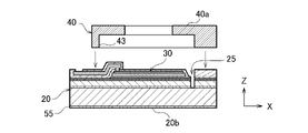
- FIG. 1A is a top view of the transducer 10A
- FIG. 1B is a cross-sectional view taken along the line IB-IB in FIG. 1A
- 1C is an exploded view showing a simplified configuration of FIG. 1B
- FIG. 1D is a cross-sectional view taken along the line ID-ID in FIG. 1B.
- the transducer 10A includes a substrate 20 containing silicon, a piezoelectric element 30 arranged on the substrate 20, and a lid 40. Further, the substrate 20 is provided around the film body portion 21 having a front surface (first surface) 21a and a back surface (second surface) 21b facing in opposite directions in the thickness direction, and around the film body portion 21. It has a frame body portion (support portion) 22 connected to a part of the outer edge 21c of the film body portion 21. The frame body portion 22 surrounds the film body portion 21 when the film body portion 21 is viewed from the thickness direction of the film body portion 21.
- the piezoelectric element 30 is arranged on the first surface of the film body portion 21 to control or detect the displacement of the film body portion 21 in the Z direction. That is, when the transducer 10A is used as a speaker, the piezoelectric element 30 vibrates the film body portion 21 in the Z direction. On the other hand, when the transducer 10A is used as a microphone, the piezoelectric element 30 detects the displacement of the film body portion 21.
- the substrate 20 includes an active layer 51 which is a semiconductor layer, a support layer 52 which is a semiconductor layer, and an SOI (BOX layer, an oxide layer) 53 arranged between the active layer 51 and the support layer 52. Silicon on Insulator) board. Further, the active layer 51, the interlayer insulating layer 53, and the support layer 52 are laminated in order in the Z direction. That is, the semiconductor layer and the oxide layer are laminated with each other in the Z direction.
- the film body portion 21 is formed of, for example, the active layer 51, and the frame body portion 22 is formed of, for example, the active layer 51, the interlayer insulating layer 53, and the support layer 52.
- the substrate 20 may be a substrate containing silicon and is not limited to the SOI substrate.
- the substrate 20 may be a silicon substrate having no interlayer insulating layer.
- An oxide film 54 is formed on the front surface 20a of the substrate 20 which is the outer surface of the active layer 51, and the oxide film 55 is formed on the back surface 20b of the substrate 20 which is the outer surface of the support layer 52 (see FIG. 4A). ..
- the stacking directions of the active layer 51, the support layer 52, and the interlayer insulating layer 53 are the Z direction, and the two directions orthogonal to the Z direction and orthogonal to each other are the X direction and the Y direction.
- the Z direction is also the thickness direction of each of the substrate 20, the piezoelectric element 30, and the film body portion 21, and is also the direction in which the substrate 20 and the lid 40 are laminated.
- the film body portion 21, the frame body portion 22, and the projecting portion 24 described later are integrally formed from the substrate 20 which is a single member.
- the film body portion 21 is a thin film that develops in the X direction and the Y direction, and has a thickness (for example, 2 to 3 ⁇ m) that can be displaced (flexible and distorted) in the Z direction. Further, the film body portion 21 has a front surface (first surface) 21a and a back surface (second surface) 21b facing in opposite directions in the Z direction. The front surface 21a faces the lid 40, and the back surface 21b faces the space 23. When the substrate 20 is an SOI substrate, the back surface 21b of the film body portion 21 may remain covered with the interlayer insulating layer 53 (see FIG. 1B).
- a part of the outer edge 21c of the film body portion 21 when viewed from the Z direction forms a connecting portion 21d connected to the frame body portion 22.
- the remaining portion of the outer edge 21c other than the connecting portion 21d is separated from the frame body portion 22.
- a slit 25 is interposed between the remaining portion of the outer edge 21c and the frame body portion.
- the remaining portion of the outer edge 21c includes the facing portion 21e facing the connecting portion 21d. That is, the film body portion 21 includes the connecting portion 21d as a fixed end and the facing portion 21e as a free end, and functions as a cantilever that is displaced (vibrated) in the Z direction.
- the film body portion 21 is formed together with the space 23 by, for example, etching the back surface 22b of the frame body portion 22 (substrate 20).
- the frame body portion 22 has a frame-like shape that surrounds the film body portion 21 when the substrate 20 is viewed from the Z direction.
- the frame body portion 22 has an inner surface 22c facing the outer edge 21c of the film body portion 21 across the slit 25.
- the inner surface 22c faces the outer edge 21c of the film body portion 21 across the slit 25.
- the substrate 20 is formed with a space 23 surrounded by the back surface 21b of the film body portion 21 and the inner surface 22c of the frame body portion 22. That is, the substrate 20 has a recess having the back surface 21b of the film body portion 21 as the bottom surface and the inner surface 22c of the frame body portion 22 as the side surface.
- the slit 25 penetrates the substrate 20 in the Z direction through the space 23.
- the width of the slit 25 is, for example, 10 ⁇ m.
- the slit 25 is formed by etching one surface of the substrate 20 including the front surface (first surface) 21a of the film body portion 21. Therefore, the width of the slit 25 can be set with high accuracy.
- the front surface 21a of the film body portion 21 and the front surface 22a of the frame body portion 22 are also formed from one surface of the substrate 20 with the formation of the slit 25. If the bending of the film body portion 21 is not taken into consideration, the heights of the two in the Z direction are the same.
- the lid 40 is attached to the frame 22 by adhesive, and covers the front surface 21a of the film 21 with a space (interval) 41 described later in between.
- the lid 40 is made of a semiconductor material containing, for example, silicon (Si).
- the lid 40 has a front surface 40a and a back surface 40b facing in opposite directions in the Z direction.
- An opening 43 is formed on the back surface 40b of the lid 40.
- the inner surface (recess) 44 of the opening 43 forms a space 41 in the lid 40.
- the space 41 communicates with the external space of the transducer 10A through the through hole 42 formed in the front surface 40a.
- the through hole 42 overlaps with at least a part of the piezoelectric element 30 when viewed from the Z direction.
- the opening area of the through hole 42 is smaller than the area of the membrane body portion 21, and the opening area of the opening 43 and the space 41 is larger than the area of the membrane body portion 21.
- the inner surface 44 of the opening 43 comes into contact with the film body 21 when the film body 21 is deformed. This prevents excessive bending of the film body portion 21. It also suppresses gas leakage from the slit 25, which will be described later. However, it is also possible to omit the lid 40 according to the specifications of the transducer.
- the piezoelectric element 30 is arranged on the front surface 21a of the film body portion 21 so as to face the opening 43 of the lid body 40.
- the piezoelectric element 30 may be installed on the front surface 22a of the frame body portion 22 and the front surface 21a of the film body portion 21 so as to straddle the outer edge 21c of the film body portion 21.
- the piezoelectric element 30 includes a pair of electrodes 31 and 33 and a piezoelectric film 32 sandwiched between the pair of electrodes 31 and 33.
- the pair of electrodes 31, 33 and the piezoelectric film 32 have a shape corresponding to the shape of the film body portion 21.
- the electrode 31, the piezoelectric film 32, and the electrode 33 are sequentially laminated along the Z direction on the front surface 21a of the film body portion 21.
- the piezoelectric element 30 is formed on the film body portion 21 before the lid body 40 is attached to the frame body portion 22.
- the film body portion 21 is displaced due to the expansion and contraction of the piezoelectric film 32. Specifically, the tip end side of the film body portion 21 is displaced so as to warp along the Z direction.
- the film body portion 21 By repeatedly applying the drive voltage to the pair of electrodes 31 and 33, the film body portion 21 alternately repeats the displacement toward the space 23 side and the displacement toward the space 41 side. That is, the film body portion 21 vibrates in the Z direction. Such vibration of the membrane body portion 21 causes the air around the membrane body portion 21 to vibrate, and a sound wave is generated. This sound wave propagates to the external space of the transducer 10A through the through hole 42 of the lid 40.
- the electrodes 31 and 33 are formed of a conductive metal thin film such as platinum, molybdenum, iridium, or titanium.
- the electrode 31 is located on the upper surface of the piezoelectric film 32, and the electrode 33 is located on the lower surface of the piezoelectric film 32.
- the piezoelectric film 32 is made of, for example, lead zirconate titanate (PZT).
- PZT lead zirconate titanate
- the piezoelectric film 32 may be made of aluminum nitride (AlN), zinc oxide (ZnO), lead titanate (PbTIO 3 ), or the like.
- the front surface 22a of the piezoelectric element 30 and the frame body portion 22 around the piezoelectric element 30 is covered with a protective film (first protective film) 57 containing, for example, alumina as a protective film 56.
- first protective film a protective film
- second protective film containing, for example, tetraethoxysilane (TEOS) as a protective film 56.
- TEOS tetraethoxysilane
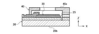
- FIG. 2 is a cross-sectional view taken along the line II-II in FIG. 1A, which is an enlarged view of the periphery of the facing portion 21e of the film body portion 21.
- 3A to 3C are rear views of the substrate 20.
- the substrate 20 has a protrusion 24.
- the projecting portion 24 projects from the region of the back surface 21b of the film body portion 21 including at least a part of the remaining portion of the outer edge 21c in the thickness direction of the film body portion 21.
- the projecting portion 24 is integrally formed with the film body portion 21, and projects from the outer edge 21c of the film body portion 21 toward the space 23 in the frame body portion 22.
- the gap between the protruding portion 24 and the inner surface 22c of the frame body portion 22 is continuous with the slit 25.
- the protruding portion 24 is arranged on the facing portion 21e facing the connecting portion 21d among the remaining portions of the outer edge 21c of the film body portion 21 other than the connecting portion 21d. Further, the protruding portion 24 may be extended along the outer edge 21c. Further, when the film body portion 21 is viewed from the Z direction, a part of the interlayer insulating layer 53 overlaps with the protruding portion 24. When the thickness of the film body portion 21 is smaller than the original thickness of the active layer 51, a part of the interlayer insulating layer 53 is included in the protruding portion 24.
- the height of the protruding portion 24 in the Z direction is set in consideration of the maximum amplitude of the film body portion 21 and the value of the width w1 of the slit 25. Its height is, for example, 3 ⁇ m to several hundred ⁇ m. Further, the thickness of the protruding portion 24 is set in consideration of the mechanical strength of the protruding portion 24 and the weight of the film body portion 21. Its thickness is, for example, 10 ⁇ m to 100 ⁇ m. The thickness referred to here is the maximum length of the protruding portion 24 in the direction parallel to the back surface 21b of the film body portion 21.
- the protrusion 24 extends the gap of the width w1 defined by the slit 25 in the Z direction. Therefore, as compared with the case where the protrusion 24 is not provided, the change in the width of the slit 25 at the time of vibration is suppressed, and the flow of gas between the space 23 and the space 41 is suppressed. As a result, the above-mentioned cancellation of sound pressure is suppressed. For example, it is possible to increase the sound pressure in the bass range where the sound pressure is likely to be offset. That is, the reproducibility of the sound that should be originally obtained can be improved.
- the substrate 20 may have at least one reinforcing portion 26.
- the reinforcing portion 26 projects from the back surface 21b of the film body portion 21 in the Z direction (in other words, toward the space 23) and connects to the protruding portion 24. Further, the reinforcing portion 26 extends from the protruding portion 24 toward the connecting portion 21d of the film body portion 21.
- the reinforcing portion 26 is provided on the straight line 12 of the membrane body portion 21 extending from the connecting portion 21d of the membrane body portion 21 to the facing portion 21e of the membrane body portion 21.
- the straight line 12 connects the center of the connecting portion 21d and the center of the facing portion 21e of the outer edge 21c facing the connecting portion 21d.
- the length of the reinforcing portion 26 may be equal to or less than the length from the facing portion 21e to the connecting portion 21d.
- the reinforcing portion 26 functions as a rib for preventing damage due to excessive deformation of the protruding portion 24. Further, the reinforcing portion 26 prevents the film body portion 21 from bending, which generates unnecessary harmonics. Therefore, the amplitude of the film body portion 21 can be increased.
- the protruding portion 24 may be provided on the entire remaining portion of the outer edge 21c of the film body portion 21 other than the connecting portion 21d. In this case, the above-mentioned gas leakage is further suppressed. Further, as shown in FIG. 3C, the projecting portion 24 may have a plurality of projecting cells 24a divided along the outer edge 21c of the film body portion 21. In this case, the weight of the film body portion 21 is reduced and the elasticity of the film body portion 21 is improved as compared with the above-mentioned example provided in the entire remaining portion of the outer edge 21c.
- the planar shape of the protruding portion 24 seen from the Z direction is symmetrical with a straight line 12 connecting the center of the connecting portion 21d and the center of the facing portion 21e of the outer edge 21c facing the connecting portion 21d. It may have a line-symmetrical shape as an axis. In this case, it is possible to suppress the asymmetrical bending of the film body portion 21 and the generation of unnecessary harmonics associated therewith.
- FIGS. 4A to 4J are views showing a manufacturing process of the transducer 10A.
- FIG. 4A shows the substrate 20 before the piezoelectric element 30 is formed.
- the substrate 20 is arranged with a support base (not shown) in a state where the back surface 20b is in contact with the support base (not shown) of the manufacturing apparatus.
- a conductive layer to be an electrode 33, a piezoelectric material to be a piezoelectric film 32, and a conductive layer to be an electrode 31 are placed in a setting region 38 of the piezoelectric element 30 defined on the front surface 20a of the substrate 20.
- the piezoelectric element 30 is formed by laminating in order while appropriately etching or the like.
- the protective film 57 is formed on the piezoelectric element 30 and the front surface 20a around the piezoelectric element 30.
- the protective film 57 is, for example, a film containing alumina (Al 2 O 3 ), and its thickness is, for example, 80 nm.
- the protective film 58 and the wiring 34 are formed on the protective film 57.
- the protective film 58 is, for example, a film (TEOS film) containing tetraethoxysilane (TEOS).
- the protective film 58 is formed before and after the formation of the wiring 34, and its thickness is, for example, 1.5 ⁇ m.
- a chemical vapor deposition method such as a thermal CVD method or a plasma CVD method can be used.
- the wiring 34 and the electrode 33 are electrically connected by forming a contact between them.
- the region of the protective film 58 including the formation positions of the piezoelectric element 30 and the slit 25 is removed by etching.
- the vibrating portion including the film body portion 21 becomes thinner, and the weight can be reduced.
- the protective film 58 may be etched using a resist patterned by a general photolithography method as a mask. Remove the resist with oxygen plasma, sulfuric acid, etc.
- As an etching method for the protective film 58 wet etching using hydrofluoric acid or dry etching such as reactive ion etching can be used.
- the active layer 51 at the position where the slit 25 is formed is etched to form the slit 25. This etching is performed until the slit 25 reaches a predetermined depth (for example, a depth reaching the interlayer insulating layer 53).
- a silicon oxide film as a mask material is deposited on the active layer 51.
- a deposition method a thermal CVD method or a plasma CVD method can be used.
- the resist is patterned on the mask material.
- a patterning method a general photolithography method can be used.
- the mask material is etched using the patterned resist as a mask.
- the mask material has an opening in the portion where the slit 25 is formed.
- dry etching such as reactive ion etching can be used.
- the lid 40 is attached to the substrate 20 by adhesive or the like.
- the protective film 56 is located between the lid 40 and the substrate 20.
- the lid 40 faces the region where the opening 43 includes the piezoelectric element 30 and the slit 25 with respect to the substrate 20. Positioned to do so.
- the support base (not shown) is separated from the back surface 20b of the substrate 20. Then, as shown in FIG. 4G, the oxide film 55 formed on the back surface 20b is removed by etching.
- the resist 61 is applied to the back surface 20b. Then, using a general photolithography method, the resist 61 is removed from the region 70 corresponding to the film body portion 21 and the slit 25.
- the support layer 52 of the substrate 20 is etched (removed) using the patterned resist 61 until a thickness substantially equal to the height of the protrusion 24 is obtained. Further, the resist 61 is reapplied to the surface 20c of the substrate 20 formed by this etching, and the resist 61 is patterned so as to remain only at the position corresponding to the protrusion 24. Then, the surface 20c is etched using the patterned resist 61 to remove the support layer 52 and the interlayer insulating layer 53 to form the protruding portion 24 (see FIG. 4J). In this etching, a part of the active layer 51 may be removed depending on the thickness of the film body portion 21. Alternatively, the interlayer insulating layer 53 may be left.
- the second embodiment will be described.
- the configuration of the transducer 10B according to the second embodiment is the same as the configuration of the transducer 10A according to the first embodiment. Therefore, in the following description, the differences from the first embodiment will be described, and the same reference numerals will be given to the configurations common to both embodiments, and the description thereof will be omitted.
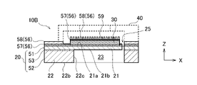
- the transducer 10B according to the second embodiment may or may not have a protrusion 24 (see FIG. 1B). In the figure according to the second embodiment, the protrusion 24 and the wiring 34 are omitted for convenience of explanation.
- FIG. 5 is a diagram for explaining the tendency of the cantilever 80 to warp.
- the Z direction in the figure is defined as the vertical direction
- the X direction is defined as the horizontal direction
- the upper side of the figure is defined as the upper side
- the lower side of the figure is defined as the lower side.
- gravity and the internal stress of the cantilever 80 are not taken into consideration.
- the cantilever 80 has the same thickness as the film body portion 21, and has an upper surface 80a and a lower surface 80b facing in opposite directions in the Z direction.
- the cantilever 80 extends in the X direction, and only one end thereof is connected to the support portion 82, and the portion other than the one end portion is separated from all members such as the support portion 82. That is, the cantilever 80 has a fixed end 80c connected to the support portion 82 and a free end 80d that is freely displaced in the Z direction.
- the support portion 82 surrounds the cantilever 80 in the same manner as the frame body portion 22. Further, the cantilever 80 and the support portion 82 are integrally formed from a substrate containing silicon, which is a single member. If there is no external force applied to the cantilever 80, the upper surface 80a of the cantilever 80 and the upper surface 80a of the support portion 82 are located in the same reference surface 86.
- an oxide film 84 as a protective film is formed on the upper surface 80a of the cantilever 80.
- the oxide film 84 is formed at the time of manufacturing the cantilever 80. Since the cantilever 80 is heated when the oxide film 84 is formed, when the temperature of the cantilever 80 drops to room temperature, a film stress (internal stress) is generated in the oxide film 84, and the force contracts in the plane direction. The cantilever 80 is warped with the upper surface 80a inside.
- the free end 80d of the cantilever 80 is displaced above the position when there is no film stress (that is, the position of the reference surface 86).
- an object 88 having an inner surface 88a facing the cantilever 80 is installed on the support portion 82 as in the lid 40 (see FIG. 1B)
- the distance between the inner surface 88a and the free end 80d in the Z direction is the cantilever 80.
- the maximum amplitude of the cantilever 80 is limited by the warp of the cantilever 80.
- the amount of warping (degree of warping) of the cantilever 80 changes depending on the magnitude of the film stress of the film formed on the surface thereof. For example, there was a significant difference in the amount of warpage of the cantilever 80 between the case where the oxide film 84 was formed by the thermal oxidation method and the case where the oxide film 84 was formed by the CVD method. This suggests that it is possible to adjust the amount of warpage of the cantilever 80 by controlling the film stress of the formed film.
- the amount of warpage of the film body portion 21 is adjusted by controlling the film stress of the substance formed on the front surface (first surface) 21a of the film body portion 21. I know I can do it.
- this substance is the piezoelectric element 30 and the protective film 56.
- the protective film 56 is formed on the front surface 20a of the piezoelectric element 30 and the substrate 20 around it, and contains the protective film 57 containing alumina (Al 2 O 3 ), or the protective film 57 and tetraethoxy. Includes a protective film 58 containing silane (TEOS).
- TEOS silane
- the protective film 58 on the piezoelectric element 30 is removed. However, as described later, it may remain in the second embodiment.
- the material of the protective film 56 is not limited to the above-mentioned one, and the protective film 56 may include a film having three or more layers.
- 6 (a) and 6 (b) are views showing a change in the neutral position of the facing portion 21e of the membrane body portion 21 due to a change in the warp of the membrane body portion 21.
- the neutral position of the facing portion 21e is a position (height) of the facing portion 21e in the Z direction in a state where the film body portion 21 is not subjected to an external force by the piezoelectric element 30 (neutral state).
- FIG. 6A is a diagram showing a change in the neutral position of the facing portion 21e according to the area of the piezoelectric element 30.
- the vertical axis indicates the neutral position of the facing portion 21e along the Z direction
- the horizontal axis indicates the area of the piezoelectric element 30.
- the area of the piezoelectric element 30 is the edge portion 30b (see FIG. 8A) of the piezoelectric element 30 close to the facing portion 21e with the position of the edge portion 30a (see FIG. 8A) of the piezoelectric element 30 close to the connecting portion 21d fixed. It is changed by changing the position along the X direction. However, in any area, the width of the piezoelectric element 30 along the connection portion 21d is constant, and the thickness of the piezoelectric element 30 is also constant.
- the degree of uneven distribution is an index showing how close the piezoelectric element 30 is to the connection portion 21d, and is defined by, for example, the ratio of the distance g2 to the distance g1 along the X direction (see FIG. 8A). ..
- the interval g1 is the interval from the center 38c of the setting region 38 of the piezoelectric element 30 set on the substrate 20 including the front surface 21a to the edge portion 30a of the piezoelectric element 30.
- the interval g2 is an interval from the center 38c of the setting region 38 to the center 30c of the piezoelectric element 30. For example, when the degree of uneven distribution is zero, the piezoelectric element 30 is formed over the entire setting region 38.
- the center 30c of the piezoelectric element 30 is located at a position close to the connection portion 21d from the center 38c of the setting region 38.
- the neutral position of the facing portion 21e rises as the degree of uneven distribution decreases.
- FIG. 6B is a diagram showing a change in the neutral position of the facing portion 21e according to the film thickness of the protective film 56 (see FIGS. 8B, 9B, etc.) covering the piezoelectric element 30.
- the above-mentioned film thickness is a value obtained by spatially averaging the film thickness of the protective film 56 on the film body portion 21.
- the neutral position of the facing portion 21e descends as the film thickness of the protective film 56 increases.
- the piezoelectric element 30 when the area of the piezoelectric element 30 (unevenness of the piezoelectric element 30) increases, the neutral position of the facing portion 21e rises, and when the film thickness of the protective film 56 increases, the neutral position of the facing portion 21e descends. That is, the piezoelectric element 30 has a film stress that warps the film body 21 with the back surface 21b inside, while the protective film 56 has a film stress that warps the film body 21 with the front surface 21a inside. In other words, these film stresses act on the film body portion 21 so as to warp in opposite directions. Therefore, by changing the combination of the area (uneven distribution) of the piezoelectric element 30 and the film thickness of the protective film 56, it is possible to control the amount of warpage and the direction of warpage of the film body portion 21 in the neutral state.
- the degree of uneven distribution of the piezoelectric element 30 is set, and the film thickness of the protective film 56 is set in consideration of this degree of uneven distribution.
- the film thickness of the protective film 56 may be set, and the degree of uneven distribution of the piezoelectric element 30 may be set in consideration of this film thickness.
- the thickness of the protective film 56 is such that the protective film 56 is linearly directed from the connecting portion 21d toward the facing portion 21e or the back surface 21b due to the resultant force of the film stress of the protective film 56 and the film stress of the piezoelectric element 30. It will be set to a value that stretches while warping sideways (with the back surface 21b inside).
- the film body portion 21 coincides with the front surface 22 a of the frame body portion 22, or the film body portion 21 warps with the back surface 22 b inside. It warps in the space 23 in the frame body portion 22). Since the neutral position of the facing portion 21e is located in the space 23 in the frame body portion 22, the neutral position of the facing portion 21e and the lid 40 are compared with the case where the film body portion 21 is warped with the front surface 21a inside. The spacing between the inner surfaces 44 increases. Therefore, the movable range of the film body portion 21 can be improved.
- the transducer 10B when the transducer 10B is used as a speaker, the maximum amplitude of the film body portion 21 according to the voltage applied to the piezoelectric element 30 can be increased, the dynamic range can be improved, and the sound reproducibility can be improved. Further, when the transducer 10B is used as a microphone, the maximum amplitude of the film body portion 21 can be expanded, and the dynamic range of the detected sound pressure can be improved.
- the piezoelectric element 30 projects (exposes) toward the lid 40 with respect to the front surface 22a of the frame body portion 22.
- the part is reduced. Therefore, it is possible to avoid contacting the lid body 40 with the piezoelectric element 30 or the like or reduce the contact probability when the lid body 40 is adhered to the frame body portion 22.
- the height of the lid 40 in the Z direction can be reduced. That is, the transducer 10B can be miniaturized.
- FIG. 8A is a top view of the substrate 20 according to the first example of the present embodiment.
- FIG. 8B is a cross-sectional view taken along the line VIIIB-VIIIB in FIG. 8A.
- the piezoelectric element 30 is unevenly distributed in the region 39 of the front surface 21a of the film body portion 21 near the connecting portion 21d.
- the protective film 56 includes the unevenly distributed piezoelectric element 30 and the front surface 21a of the film body portion 21 around it (in other words, the portion of the front surface 21a where the piezoelectric element 30 is not arranged). cover.
- the piezoelectric element 30 is formed on the front surface 20a of the substrate 20 at a position having a desired uneven distribution degree.
- the increase of the degree of uneven distribution suppresses the increase of the facing portion 21e, and the film body portion 21 is linearly stretched or the back surface.
- the film thickness of the protective film 56 required to obtain a warped state with the 21b inside is reduced. Therefore, the weight of the film body portion 21, the piezoelectric element 30, and the protective film 56 as a whole can be reduced.
- only the protective film 57 is formed in the setting region 38 as the protective film 56.
- a protective film 58 having a desired film thickness may be formed (remained) on the protective film 57 according to the set film stress.
- FIG. 9A is a top view of the substrate 20 according to the second example of the present embodiment.
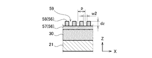
- 9B is a cross-sectional view taken along the line IXB-IXB in FIG. 9A.
- FIG. 9C is a partially enlarged view of a cross section of the film body portion 21 and the protective film 56 shown in FIG. 9B.
- the piezoelectric element 30 is formed on the entire surface of the setting region 38.
- the protective film 56 on the piezoelectric element 30 includes a plurality of recesses 59.
- the plurality of recesses 59 are spaced from the connecting portion 21d of the outer edge 21c of the film body portion 21 toward the facing portion 21e of the outer edge 21c (for example, in the X direction), and the facing portion from the connecting portion 21d of the outer edge 21c to the outer edge 21c. It extends in a direction intersecting the direction toward 21e (for example, the Y direction). That is, as shown in FIG. 9A, the plurality of recesses 59 are formed in stripes on the piezoelectric element 30.
- the recess 59 is formed by forming a resist patterned on the protective film 56 and etching. For example, when the protective film 58 shown in FIG. 4D is removed, a patterned resist is formed on the protective film 58, and the protective film 58 at the portion to be the recess 59 is etched.
- the average value of the film thickness of the protective film 56 decreases due to the formation of the recess 59. That is, the film stress of the protective film 56 can be changed only by forming the recess 59.
- the reduction width of the average value of the film thickness can be appropriately adjusted by setting the depth dz, the width w2, or the pitch p (FIG. 9C) of the recess 59.
- the protective film 56 includes a plurality of protective films made of materials having different etching rates, such as the protective film 57 and the protective film 58, the protective film 58 on the outermost surface (in this example, the protective film 58) A recess 59 is formed so that the protective film (protective film 57 in this example) under the protective film is exposed.
- the depth dz of the recess 59 is equal to the film thickness of the outermost protective film, it becomes easy to control the etching of the outermost protective film.
- the piezoelectric elements 30 may be unevenly distributed as in the first example. Due to the uneven distribution of the piezoelectric element 30 and the formation of the recess 59, the variable width of the resultant force of the respective film stresses of the piezoelectric element 30 and the protective film 56 is expanded, and the resultant force can be easily set according to the dimensions of the film body such as the film thickness. Become.
- the piezoelectric element 30 and the protective film 56 viewed from the Z direction may be positioned line-symmetrically with the straight line 12 as the axis of symmetry. In this case, it becomes easy to apply the resultant force of the film stresses of the piezoelectric element 30 and the protective film 56 to the film body portion 21 in a line symmetry with the straight line 12 as the axis of symmetry, and the warp of the line symmetric film body portion 21 becomes easy. It will be easier to obtain.
- the plurality of recesses 59 may be positioned line-symmetrically with the straight line 12 as the axis of symmetry. Also in this case, it becomes easy to apply the resultant force of the film stresses of the piezoelectric element 30 and the protective film 56 to the film body portion 21 in a line symmetry with the straight line 12 as the axis of symmetry, and the warp of the line symmetric film body portion 21. Is easy to obtain.
- each recess 59 are not limited to a shape that extends in one direction with a constant width. That is, as long as the desired warp of the film body portion 21 can be obtained, each recess 59 may have a shape such as a circle, an ellipse, a rectangle, or another polygon when viewed from the Z direction.
- the transducer 10B includes a substrate 20 containing silicon and a piezoelectric element 30 arranged on the substrate 20.
- the substrate 20 has a film body portion 21 having a first surface (front surface) 21a and a second surface (back surface) 21b facing in opposite directions in the thickness direction (Z direction), and a film body portion from the thickness direction. It has a frame body portion 22 that surrounds the film body portion 21 when the 21 is viewed.
- the piezoelectric element 30 is arranged on at least a part of the first surface 21a of the film body portion 21.
- the piezoelectric element 30 and the first surface 21a around the piezoelectric element 30 are covered with a protective film 56.
- a part of the outer edge 21c of the film body portion 21 when viewed from the thickness direction forms a connecting portion 21d connected to the support portion 82, and the rest of the outer edge 21c other than the connecting portion 21d is separated from the frame body portion 22 and The facing portion 21e facing the connecting portion 21d is included.
- the film thickness of the protective film 56 is such that the protective film 56 linearly or the second surface 21b from the connecting portion 21d toward the facing portion 21e by the resultant force of the film stress of the protective film 56 and the film stress of the piezoelectric element 30. It is set to a value that stretches while warping inward.
- the substrate 20 may have a semiconductor layer and an oxide layer laminated on each other in the Z direction.
- the semiconductor layer constitutes the active layer 51 and the support layer 52
- the oxide layer constitutes the interlayer insulating layer 53.
- the piezoelectric element 30 may be unevenly distributed in a region close to the connection portion 21d on the first surface 21a.
- the protective film 56 may include a plurality of recesses 59.
- the plurality of recesses 59 extend in a direction intersecting the direction from the connecting portion 21d of the outer edge 21c toward the facing portion 21e of the outer edge 21c at intervals in the direction from the connecting portion 21d of the outer edge 21c toward the facing portion 21e of the outer edge 21c. You may.
- the piezoelectric element 30 and the protective film 56 viewed from the thickness direction are positioned line-symmetrically with the straight line 12 connecting the center of the connecting portion 21d and the center of the facing portion 21e of the outer edge 21c facing the connecting portion 21d as the axis of symmetry. May be good.
- the transducer 10B may further include a lid 40, which is adhered to the frame body 22 and covers the first surface 21a of the film body 21 with a space 41 in between.
- the lid 40 may have an opening that overlaps with at least a part of the piezoelectric element 30 when viewed from the thickness direction.
- the protective film 56 includes a protective film (first protective film) 57 that covers the surface of the piezoelectric element 30 and the frame portion 22 around the piezoelectric element 30, and a protective film (second protective film) 58 that covers the protective film 57. But it may be.
- the protective film 58 may cover a region other than the region including the film body portion 21 and the piezoelectric element 30 (for example, the region facing the setting region 38 or the opening 34) in the region covered with the protective film 57. ..
- the protective film 57 may contain alumina as a component.
- the protective film 58 may contain tetraethoxysilane as a component.
- each recess 59 may have a depth equal to the film thickness of the protective film 58.
- the piezoelectric element 30 may be installed on the frame body portion 22 and on the film body portion 21 so as to straddle the connecting portion 21d of the film body portion 21.
- the substrate 20 may have a protrusion 24 protruding in the Z direction from a region including at least a part of the remaining portion of the outer edge 21c described above.
Landscapes
- Engineering & Computer Science (AREA)
- Physics & Mathematics (AREA)
- Acoustics & Sound (AREA)
- Signal Processing (AREA)
- Multimedia (AREA)
- Computer Hardware Design (AREA)
- Microelectronics & Electronic Packaging (AREA)
- Chemical & Material Sciences (AREA)
- Ceramic Engineering (AREA)
- Micromachines (AREA)
- Piezo-Electric Transducers For Audible Bands (AREA)
- Transducers For Ultrasonic Waves (AREA)
Abstract
Description
第1実施形態に係るトランスデューサ10Aの構成について説明する。
図1Aはトランスデューサ10Aの上面図、図1Bは図1A中のIB-IB断面図である。図1Cは図1Bの構成を簡略化して示した分解図、図1Dは図1B中のID-ID断面図である。
図2は、図1A中のII-II断面図であり、膜体部21の対向部21eの周囲を拡大した図である。図3A~図3Cは、基板20の背面図である。
第2実施形態について説明する。
第2実施形態に係るトランスデューサ10Bの構成は、第1実施形態に係るトランスデューサ10Aの構成と同様である。従って、以下の説明では、第1実施形態と相違する点について述べ、両実施形態に共通の構成については同一の符号を付して、その説明を割愛する。なお、第2実施形態に係るトランスデューサ10Bは突出部24(図1B参照)を有していてもよく、有さなくともよい。第2実施形態に係る図では、説明の便宜上、突出部24、配線34を省略している。
12 直線(中心線)
20 基板
21 膜体部
21a 前面(第1の面)
21b 背面(第2の面)
21c 外縁
21d 接続部
21e 対向部
22 枠体部(支持部)
23 空間
24 突出部
24a 突出セル
25 スリット
26 補強部
30 圧電素子
40 蓋体
42 貫通孔
51 活性層(半導体層)
52 支持層(半導体層)
53 層間絶縁層(BOX層、酸化物層)
Claims (18)
- シリコンを含む基板と、
前記基板上に配置された圧電素子と、を備え、
前記基板は、
厚さ方向において互いに反対方向に面した第1の面及び第2の面を有する膜体部と、
前記厚さ方向から前記膜体部を見た時に前記膜体部を取り囲んでいる枠体部と、を有し、
前記圧電素子は、前記膜体部の前記第1の面上に配置され、
前記厚さ方向から見た時の前記膜体部の外縁の一部は前記枠体部に接続された接続部を成し、前記接続部以外の前記外縁の残部は前記枠体部から離れており、
前記基板は、前記第2の面のうちの前記外縁の前記残部の少なくとも一部分を含む領域から、前記厚さ方向に突出する突出部を有する
トランスデューサ。 - 前記基板は、前記厚さ方向に互いに積層された半導体層と酸化物層とを有する
請求項1に記載のトランスデューサ。 - 前記枠体部に取り付けられた、前記膜体部の前記第1の面と間隔を置いて前記膜体部の前記第1の面を覆う蓋体を更に備える
請求項1又は2に記載のトランスデューサ。 - 前記蓋体は、前記厚さ方向から見た時に、前記圧電素子の少なくとも一部と重畳する開口を有する
請求項3に記載のトランスデューサ。 - 前記突出部は、前記外縁の前記残部のうち、前記接続部に対向する前記外縁の対向部に配置されている請求項1~4のいずれか一項に記載のトランスデューサ。
- 前記基板は、前記第2の面から前記厚さ方向に突出し、前記突出部に接続されている補強部を有する請求項5に記載のトランスデューサ。
- 前記突出部は、前記外縁の前記残部全体に配置されている請求項1~4のいずれか一項に記載のトランスデューサ。
- 前記突出部は、前記外縁に沿って分割された複数の突出セルを有する請求項1~7のいずれか一項に記載のトランスデューサ。
- 前記厚さ方向から見た前記突出部の平面形状は、前記接続部の中心と前記接続部に対向する前記外縁の対向部の中心とを結ぶ直線を対称軸とする線対称な形状である請求項1~8のいずれか一項に記載のトランスデューサ。
- 前記突出部の前記厚さ方向の高さは、3μm以上である
請求項1~8のうちのいずれか一項に記載のトランスデューサ。 - 前記膜体部の前記第2の面と平行な方向における前記突出部の最大長さは10μm~100μmである
請求項1~8のうちのいずれか一項に記載のトランスデューサ。 - 前記圧電素子は、前記接続部を跨ぐように、前記枠体部上と前記膜体部上に設置されている
請求項1~11のうちのいずれか一項に記載のトランスデューサ。 - 前記厚さ方向から前記膜体部を見た時、前記酸化物層の一部は、前記突出部と重なっている
請求項2に記載のトランスデューサ。 - 前記酸化物層の一部は前記突出部に含まれている
請求項13に記載のトランスデューサ。 - 前記蓋体は、前記基板上に形成された保護膜を介して前記枠体部に取り付けられている
請求項3又は4に記載のトランスデューサ。 - 前記保護膜は、前記圧電素子とその周囲の前記枠体部の表面を覆う第1の保護膜と、前記枠体部の前記表面において、前記膜体部と前記圧電素子を含む領域以外の領域を覆う第2の保護膜とを有する
請求項15に記載のトランスデューサ。 - 前記第1の保護膜はアルミナを成分として含む
請求項16に記載のトランスデューサ。 - 前記第2の保護膜はテトラエトキシシランを成分として含む
請求項16又は17に記載のトランスデューサ。
Priority Applications (3)
| Application Number | Priority Date | Filing Date | Title |
|---|---|---|---|
| CN202180081004.5A CN116547231A (zh) | 2020-12-01 | 2021-10-27 | 换能器 |
| JP2022566785A JPWO2022118575A1 (ja) | 2020-12-01 | 2021-10-27 | |
| US18/319,234 US20230292055A1 (en) | 2020-12-01 | 2023-05-17 | Transducer |
Applications Claiming Priority (2)
| Application Number | Priority Date | Filing Date | Title |
|---|---|---|---|
| JP2020199459 | 2020-12-01 | ||
| JP2020-199459 | 2020-12-01 |
Related Child Applications (1)
| Application Number | Title | Priority Date | Filing Date |
|---|---|---|---|
| US18/319,234 Continuation US20230292055A1 (en) | 2020-12-01 | 2023-05-17 | Transducer |
Publications (1)
| Publication Number | Publication Date |
|---|---|
| WO2022118575A1 true WO2022118575A1 (ja) | 2022-06-09 |
Family
ID=81853637
Family Applications (1)
| Application Number | Title | Priority Date | Filing Date |
|---|---|---|---|
| PCT/JP2021/039628 WO2022118575A1 (ja) | 2020-12-01 | 2021-10-27 | トランスデューサ |
Country Status (4)
| Country | Link |
|---|---|
| US (1) | US20230292055A1 (ja) |
| JP (1) | JPWO2022118575A1 (ja) |
| CN (1) | CN116547231A (ja) |
| WO (1) | WO2022118575A1 (ja) |
Citations (3)
| Publication number | Priority date | Publication date | Assignee | Title |
|---|---|---|---|---|
| JPS5961698U (ja) * | 1982-10-18 | 1984-04-23 | オムロン株式会社 | 電気音響変換器 |
| JP2001069596A (ja) * | 1999-08-25 | 2001-03-16 | Hosiden Corp | 半導体エレクトレットコンデンサマイクロホンの製造方法及び半導体エレクトレットコンデンサマイクロホン |
| JP2019161030A (ja) * | 2018-03-14 | 2019-09-19 | 新日本無線株式会社 | 圧電素子 |
-
2021
- 2021-10-27 CN CN202180081004.5A patent/CN116547231A/zh active Pending
- 2021-10-27 JP JP2022566785A patent/JPWO2022118575A1/ja active Pending
- 2021-10-27 WO PCT/JP2021/039628 patent/WO2022118575A1/ja active Application Filing
-
2023
- 2023-05-17 US US18/319,234 patent/US20230292055A1/en active Pending
Patent Citations (3)
| Publication number | Priority date | Publication date | Assignee | Title |
|---|---|---|---|---|
| JPS5961698U (ja) * | 1982-10-18 | 1984-04-23 | オムロン株式会社 | 電気音響変換器 |
| JP2001069596A (ja) * | 1999-08-25 | 2001-03-16 | Hosiden Corp | 半導体エレクトレットコンデンサマイクロホンの製造方法及び半導体エレクトレットコンデンサマイクロホン |
| JP2019161030A (ja) * | 2018-03-14 | 2019-09-19 | 新日本無線株式会社 | 圧電素子 |
Also Published As
| Publication number | Publication date |
|---|---|
| US20230292055A1 (en) | 2023-09-14 |
| CN116547231A (zh) | 2023-08-04 |
| JPWO2022118575A1 (ja) | 2022-06-09 |
Similar Documents
| Publication | Publication Date | Title |
|---|---|---|
| KR101414531B1 (ko) | 전기기계 변환장치 및 그 제조방법 | |
| US8509462B2 (en) | Piezoelectric micro speaker including annular ring-shaped vibrating membranes and method of manufacturing the piezoelectric micro speaker | |
| EP2320678B1 (en) | Microphone device with accelerometer for vibration compensation | |
| EP1953839B1 (en) | Piezoelectric Element, Ink Jet Head, and Ink Jet Recording Device | |
| KR101561662B1 (ko) | 곡선형 리드선들을 가진 압전형 마이크로 스피커 및 그 제조 방법 | |
| WO2013121640A1 (ja) | 静電容量型センサ及びその製造方法 | |
| TWI738804B (zh) | Mems裝置與製程 | |
| US20110075867A1 (en) | Piezoelectric micro speaker including weight attached to vibrating membrane and method of manufacturing the same | |
| JP2008098524A (ja) | 振動センサ及びその製造方法 | |
| KR20080008246A (ko) | 실리콘 마이크 및 그의 제조 방법 | |
| US20150230011A1 (en) | Acoustic transducer | |
| US20090190782A1 (en) | Vibration transducer | |
| CN108419189A (zh) | 压电传感器 | |
| WO2022118575A1 (ja) | トランスデューサ | |
| JP4273438B2 (ja) | マイクロフォン | |
| JP5708290B2 (ja) | Memsデバイスの製造方法、memsデバイス、圧力センサー、及び超音波トランスデューサー | |
| US8136399B2 (en) | Angular rate sensor with vibrator | |
| JP4944494B2 (ja) | 静電容量型センサ | |
| CN113545108B (zh) | 为达更高信噪比的电容式麦克风传感器设计及制造方法 | |
| KR101703379B1 (ko) | 막을 갖는 멤스 장치 및 그 제조 방법 | |
| WO2022110349A1 (zh) | 一种压电式麦克风及其制作方法 | |
| GB2551796A (en) | MEMS device and process | |
| WO2022264654A1 (ja) | トランスデューサおよびその製造方法 | |
| WO2022075114A1 (ja) | 積層構造体および積層構造体の製造方法 | |
| KR101066102B1 (ko) | 마이크로 스피커 및 그의 제조 방법 |
Legal Events
| Date | Code | Title | Description |
|---|---|---|---|
| 121 | Ep: the epo has been informed by wipo that ep was designated in this application |
Ref document number: 21900330 Country of ref document: EP Kind code of ref document: A1 |
|
| ENP | Entry into the national phase |
Ref document number: 2022566785 Country of ref document: JP Kind code of ref document: A |
|
| WWE | Wipo information: entry into national phase |
Ref document number: 202180081004.5 Country of ref document: CN |
|
| NENP | Non-entry into the national phase |
Ref country code: DE |
|
| 122 | Ep: pct application non-entry in european phase |
Ref document number: 21900330 Country of ref document: EP Kind code of ref document: A1 |