WO2022118559A1 - 光照射医療装置 - Google Patents
光照射医療装置 Download PDFInfo
- Publication number
- WO2022118559A1 WO2022118559A1 PCT/JP2021/038866 JP2021038866W WO2022118559A1 WO 2022118559 A1 WO2022118559 A1 WO 2022118559A1 JP 2021038866 W JP2021038866 W JP 2021038866W WO 2022118559 A1 WO2022118559 A1 WO 2022118559A1
- Authority
- WO
- WIPO (PCT)
- Prior art keywords
- window
- shaft
- tubular member
- light
- medical device
- Prior art date
- Legal status (The legal status is an assumption and is not a legal conclusion. Google has not performed a legal analysis and makes no representation as to the accuracy of the status listed.)
- Ceased
Links
Images






Classifications
-
- A—HUMAN NECESSITIES
- A61—MEDICAL OR VETERINARY SCIENCE; HYGIENE
- A61M—DEVICES FOR INTRODUCING MEDIA INTO, OR ONTO, THE BODY; DEVICES FOR TRANSDUCING BODY MEDIA OR FOR TAKING MEDIA FROM THE BODY; DEVICES FOR PRODUCING OR ENDING SLEEP OR STUPOR
- A61M25/00—Catheters; Hollow probes
- A61M25/01—Introducing, guiding, advancing, emplacing or holding catheters
- A61M25/02—Holding devices, e.g. on the body
- A61M25/04—Holding devices, e.g. on the body in the body, e.g. expansible
-
- A—HUMAN NECESSITIES
- A61—MEDICAL OR VETERINARY SCIENCE; HYGIENE
- A61N—ELECTROTHERAPY; MAGNETOTHERAPY; RADIATION THERAPY; ULTRASOUND THERAPY
- A61N5/00—Radiation therapy
- A61N5/06—Radiation therapy using light
Definitions
- the present invention relates to a light irradiation medical device for irradiating tissues such as cancer cells with light in internal lumens such as blood vessels and gastrointestinal tracts.
- a photosensitizer is administered into the body by intravenous injection or intraperitoneal administration, and the photosensitizer is accumulated in the target tissue such as cancer cells, resulting in light of a specific wavelength.
- the photosensitizer is excited by irradiating with. When the excited photosensitizer returns to the ground state, energy transformation occurs, generating reactive oxygen species.
- the target tissue can be removed by the active oxygen species attacking the target tissue. Further, in ablation (tissue cauterization) using laser light, the target tissue is irradiated with laser light and cauterized.
- an optical fiber is arranged in the catheter tube to irradiate the target tissue with light.
- Patent Document 1 discloses a device including a balloon catheter having a specified treatment window that supplies irradiation to a specified area.
- the device includes a central channel and an outer sleeve.
- the central channel is transparent into which the fiber optic probe can be inserted.
- the outer sleeve is an outer sleeve having a proximal end and a distal end used to inflate the balloon, further comprising an inflatable balloon in the vicinity of the distal end, wherein the balloon is treated at both ends. It is coated with a reflective material to define the window.
- Patent Document 2 discloses an ablation device including a shaft, a balloon, a first lumen, a second lumen, a light guide material, a diffusion member, and a tubular member.
- the balloon is provided on the tip end side of the shaft and is elastically inflatable.
- the first lumen is formed along the shaft and is for allowing fluid to flow into the balloon.
- the second lumen is formed along the shaft and is for draining the fluid from the balloon.
- the light guide material is provided along the shaft and guides the laser beam into the balloon.
- the diffusing member reflects or diffuses the laser light emitted from the light guide material in the balloon in a direction intersecting the first direction in which the light guide material is extended.
- the tubular member is provided in the balloon and surrounds the diffusion member, and has a reflective layer on the inner surface side thereof that reflects or blocks the laser light reflected or diffused by the diffusion member, and the laser light is transmitted. It has a transmission window that allows light to pass through to the outside of the reflective layer.
- Patent Document 3 discloses that a photosensitizer is administered using a delivery device in photodynamic therapy for treating a prostate disorder.
- the delivery device includes a channel inside which the guide wire is insertably received.
- the activation energy is delivered utilizing an irradiation device that includes an energy source and a channel within which a guide wire can be inserted and received.
- the guide wire is used to position the delivery device and / or the irradiation device.
- Patent Document 3 also discloses that the irradiation device can be slid, that is, rotated in the lateral direction along the guide wire.
- the irradiation position of light is determined by the treatment window provided on the balloon. Therefore, in order to change the irradiation position after expanding the balloon and fixing it in the body, it is necessary to contract the balloon and then move or rotate the catheter to the distal side or the proximal side, which is complicated. there were.
- the light irradiation position is determined by the transmission window provided in the tubular member connected to the light guide material (optical fiber). Therefore, in order to adjust the irradiation position, it is necessary to move or rotate the light guide material to the distal side or the proximal side, and this operation may damage the light guide material.
- an object of the present invention is to provide a light irradiation medical device capable of adjusting the irradiation position and irradiation range of the emitted light while preventing damage to the optical fiber.
- One embodiment of the light irradiation medical device of the present invention that has achieved the above object is a shaft having a first end and a second end in the longitudinal direction, and a cavity extending in the longitudinal direction.
- a first cylinder that is arranged in the cavity of the shaft and is rotatable around a rotation axis parallel to the longitudinal direction of the shaft, and has a first window provided in a part of the peripheral wall at the distal portion.
- a second window which is arranged in the lumen of the member and the first cylindrical member, is rotatable around a rotation axis parallel to the longitudinal direction of the shaft, and has a second window on a part of the peripheral wall at the distal portion.
- a two-cylindrical member and a light guide device arranged in the cavity of the second tubular member and movable in the longitudinal axis direction of the shaft are provided, and the light guide device is an optical fiber extending in the longitudinal axis direction.
- the optical fiber has a core and a clad that covers the radial outer side of the core, and has a non-existent portion of the clad in a part of the distal portion of the core, and is a light guide device.
- the gist is that the emitted light from the cylinder passes through the first window and the second window.
- the irradiation position of the emitted light can be adjusted by adjusting the positions where the first window and the second window overlap in the circumferential direction and the longitudinal axis direction of the shaft.
- the irradiation range of the emitted light can be adjusted by adjusting how the first window and the second window overlap. Since the irradiation position and range can be adjusted without rotating the light guide device in this way, damage to the optical fiber can be prevented.
- the first window may be longer than the second window in the circumferential direction of the shaft. Further, the first window may be longer than the second window in the longitudinal axis direction of the shaft.
- the first tubular member may be made of a material having a lower emission light passage than the first window
- the second tubular member may be made of a material having a lower emission light passage than the second window.
- a first transparent member that transmits emitted light may be arranged in the first window.
- a second transparent member that transmits emitted light may be arranged in the second window.
- the length of the first window and the second window in the longitudinal axis direction of the shaft may be larger than the length in the circumferential direction of the shaft, respectively.
- the first window and the second window may be provided within a range of a quarter length of the entire circumference of the shaft in the circumferential direction of the shaft, respectively.
- the first window and the second window may be longer than the non-existent portion of the clad.
- An expansion portion that expands outward in the radial direction of the shaft may be further provided at the distal portion of the shaft.
- the extension may be a balloon, a basket with multiple elastic wires, or a self-expandable stent.
- the first cylindrical member and the second tubular member may each have a first section in which a reinforcing material containing metal is arranged.
- the first tubular member is located distal to the first section of the first tubular member and further has a second section in which no reinforcing material is arranged, and the second tubular member is a second tubular member. It is located on the distal side of the first section of the above and further has a second section in which no reinforcing material is arranged, the first window is arranged in the second section of the first tubular member, and the first tubular member.
- the second window may not be arranged in the first section of the second tubular member, and may not be arranged in the second section of the second tubular member.
- the first tubular member is located proximal to the first section of the first tubular member and further has a third section composed of metal pipes
- the second tubular member is the second cylinder. It may further have a third section, which is located proximal to the first section of the shaped member and is composed of a metal pipe.
- a support portion for supporting the distal portion of the light guide device may be further provided at the distal end portion of the shaft.
- a reflective material that refracts the emitted light from the core toward the second window may be arranged on the inner surface of the second tubular member.
- the light guide device may have a protective tube that covers the optical fiber and has light transmission.
- the first cylindrical member has a position display portion indicating the position of the first window at its distal end
- the second tubular member has a position display portion indicating the position of the second window at its distal end. You may be doing it.
- the light guide device may not rotate about an axis parallel to the longitudinal axis of the shaft with respect to the shaft.
- the irradiation position of the emitted light can be adjusted by adjusting the position where the first window and the second window overlap in the circumferential direction and the longitudinal axis direction of the shaft.
- the irradiation range of the emitted light can be adjusted by adjusting how the first window and the second window overlap. Since the irradiation position and range can be adjusted without rotating the light guide device in this way, damage to the optical fiber can be prevented.
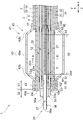
- FIG. 1 shows an enlarged cross-sectional view of the distal side of the light irradiation medical device shown in FIG.
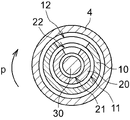
- FIG. 2 shows a sectional view taken along line III-III of the light irradiation medical device shown in FIG.
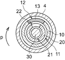
- a cross-sectional view showing a modified example of the light irradiation medical device shown in FIG. 3 is shown.
- a cross-sectional view showing another modification of the light irradiation medical device shown in FIG. 3 is shown.
- a perspective view of the first cylindrical member shown in FIG. 1 is shown.
- the perspective view of the 2nd cylindrical member shown in FIG. 1 is shown.
- a perspective view showing a modified example of the first tubular member shown in FIG. 6 is shown.
- a perspective view showing a modified example of the second tubular member shown in FIG. 7 is shown.
- FIG. 8 shows a perspective view showing a modified example of the first tubular member shown in FIG.
- a perspective view showing a modified example of the second tubular member shown in FIG. 9 is shown.
- a cross-sectional view (partial side view) showing a modified example of the light irradiation medical device shown in FIG. 2 is shown.
- a cross-sectional view showing another modification of the light irradiation medical device shown in FIG. 2 is shown.
- One embodiment of the light irradiation medical device of the present invention is a shaft having a first end and a second end in the longitudinal axis direction, a shaft having a lumen extending in the longitudinal axis direction, and the inside of the shaft.
- a second cylindrical member which is located in the cavity of the member, is rotatable around a rotation axis parallel to the longitudinal axis of the shaft, and has a second window on a part of the peripheral wall at the distal end.
- the light guide device is arranged in the lumen of the two cylindrical members and is movable in the longitudinal axis direction of the shaft, and the light guide device has an optical fiber extending in the longitudinal axis direction. It has a core and a clad that covers the radial outer side of the core, and has a non-existent part of the clad in a part of the distal portion of the core, and the emitted light from the light guide device is the first. It has a gist in that it passes through the window and the second window.
- the irradiation position of the emitted light can be adjusted by adjusting the positions where the first window and the second window overlap in the circumferential direction and the longitudinal axis direction of the shaft.
- the irradiation range of the emitted light can be adjusted by adjusting how the first window and the second window overlap. Since the irradiation position and range can be adjusted without rotating the light guide device in this way, damage to the optical fiber can be prevented.
- the light irradiation medical device is used in PDT and optical ablation to irradiate a treated portion, which is a target tissue such as a cancer cell, with light of a specific wavelength in an internal lumen such as a blood vessel or a digestive tract.
- the light irradiation medical device may be delivered to the treatment unit alone, or may be used together with a delivery catheter or an endoscope.
- endoscopic treatment a light-irradiated medical device is placed in the body through the forceps channel of the endoscope and delivered to the treatment site.
- the light irradiation medical device may be simply referred to as a device.
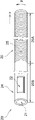
- FIG. 1 shows a side view (partial sectional view) of a light irradiation medical device according to an embodiment of the present invention.
- FIG. 2 shows an enlarged cross-sectional view of the distal side of the device shown in FIG.
- FIG. 3 represents a III-III cross-sectional view of the apparatus shown in FIG.
- the light irradiation medical device 1 includes a shaft 2, a first cylindrical member 10, a second tubular member 20, and a light guide device 30.
- the distal side of the device 1 refers to the first end side of the shaft 2 in the longitudinal axis direction x and the treatment target side.
- the proximal side of the device 1 is the second end side of the shaft 2 in the longitudinal axis direction x and refers to the hand side of the user (operator).
- the proximal side may be referred to as a proximal portion and the distal side may be referred to as a distal portion.
- each member constituting the device 1 has biocompatibility.
- the shaft 2 has a longitudinal axis direction x, a radial direction y, and a circumferential direction p.
- the shaft 2 has a first end and a second end in the longitudinal axis direction x, and has a lumen 3 extending in the longitudinal axis direction x.
- the first end may correspond to the distal end of the shaft 2 and the second end may correspond to the proximal end of the shaft 2.
- the shaft 2 has a tubular structure for arranging the first tubular member 10, the second tubular member 20, and the light guide device 30 in the lumen 3. Further, since the shaft 2 is inserted into the body, it preferably has flexibility.
- the shaft 2 is, for example, a polyolefin resin (for example, polyethylene or polypropylene), a polyamide resin (for example, nylon), a polyester resin (for example, PET), an aromatic polyether ketone resin (for example, PEEK), a polyether polyamide resin, or a polyurethane. It can be composed of a synthetic resin such as a resin, a polyimide resin, a fluororesin (for example, PTFE, PFA, ETFE), or a metal such as stainless steel, carbon steel, or nickel-titanium alloy. These may be used alone or in combination of two or more.
- a synthetic resin such as a resin, a polyimide resin, a fluororesin (for example, PTFE, PFA, ETFE), or a metal such as stainless steel, carbon steel, or nickel-titanium alloy. These may be used alone or in combination of two or more.
- the shaft 2 preferably contains a light-transmitting material.
- the light-transmitting material include (meth) acrylic resin (for example, polymethylmethacrylate (PMMA)), polycarbonate resin (for example, polydiethylene glycol bisallyl carbonate (PC)), and polystyrene-based resin (for example, both methylmethacrylate and styrene).
- acrylic resin for example, polymethylmethacrylate (PMMA)
- polycarbonate resin for example, polydiethylene glycol bisallyl carbonate (PC)
- polystyrene-based resin for example, both methylmethacrylate and styrene
- synthetic resins such as polymerized resin (MS), acrylic nitrile styrene resin (SAN)), polyamide resin (for example, nylon), and polyolefin resin.
- the shaft 2 preferably contains a light diffusing material.
- the light from the light guide device 30 is appropriately diffused when passing through the shaft 2, so that the target tissue can be evenly irradiated with the light.
- the light diffusible material include inorganic particles such as titanium oxide, barium sulfate and calcium carbonate, and organic particles such as crosslinked acrylic particles and crosslinked styrene particles.
- a first handle 71 for the operator to grip the device 1 is connected to the proximal portion of the shaft 2.
- a fluid feeder may be connected to the first handle 71.
- the fluid feeder is for supplying fluid to the inside of the balloon 41 through the lumen 3, and examples thereof include a syringe.
- the first tubular member 10 is arranged in the lumen 3 of the shaft 2 and is rotatable around a rotation axis parallel to the longitudinal axis direction x.
- a first window 12 is provided on a part of the peripheral wall at the distal portion of the first tubular member 10.
- the second tubular member 20 is arranged in the lumen 11 of the first tubular member 10 and is rotatable around a rotation axis parallel to the longitudinal axis direction x of the shaft 2.
- a second window 22 is provided on a part of the peripheral wall at the distal portion of the second tubular member 20.
- the light guide device 30 is arranged in the lumen 21 of the second tubular member 20 and is movable in the longitudinal axis direction x of the shaft 2.
- the light guide device 30 has an optical fiber 31 extending in the longitudinal direction x of the shaft 2.
- the optical fiber 31 has a core 32 and a clad 33 that covers the radial outer side of the core 32, and has a clad non-existent portion 34 in a part of the distal portion of the core 32.
- the emitted light from the light guide device 30 passes through the first window 12 and the second window 22.
- the irradiation position of the emitted light can be adjusted by adjusting the positions where the first window 12 and the second window 22 overlap in the longitudinal axis direction x and the circumferential direction p of the shaft 2.
- the irradiation range of the emitted light can be adjusted by adjusting the way in which the first window 12 and the second window 22 overlap. Since the irradiation position and range can be adjusted without rotating the light guide device 30 in this way, damage to the optical fiber 31 can be prevented.
- a guide wire can be inserted into the lumen 21 of the second tubular member 20 before the light guide device 30 is inserted.
- the guide wire is used to deliver the shaft 2 to the target tissue. That is, the device 1 may include a guide wire that extends in the longitudinal axis direction x of the shaft 2 and can be inserted into the lumen 21 of the second tubular member 20. The guide wire may be removed before the light guide device 30 is inserted into the lumen 21 of the second tubular member 20.
- the optical fiber 31 of the light guide device 30 is a transmission line that transmits an optical signal to the target tissue.
- the connector 35 provided at the proximal end of the light guide device 30 is connected to a light source such as a semiconductor laser.
- the optical fiber 31 has a core 32 and a clad 33 that covers the radial outer side of the core 32, and has a clad non-existent portion 34 in a part of the distal portion of the core 32.
- the material constituting the core 32 and the clad 33 is not particularly limited, and glass such as plastic, quartz glass, and fluoride glass can be used.
- the non-existent portion 34 of the clad refers to a portion where the clad 33 does not exist at least in a part of the circumferential direction of the core 32, and is a light emitting area of the optical fiber 31.
- the non-existent portion 34 of the clad may be simply referred to as a portion 34.
- the side irradiation type device 1 can be configured.
- the position where the non-existing portion 34 of the clad is provided in the longitudinal axis direction x of the shaft 2 is not particularly limited as long as it is a part of the distal portion of the core 32, but is provided at the portion including the distal end 32a of the core 32. It is preferable to have. This facilitates the formation of the portion 34 and also enhances the flexibility at the distal end of the light guide 30.
- the position of the distal end 34a of the portion 34 coincides with the position of the distal end 32a of the core 32. This eliminates the difficult step of forming the portion 34 while leaving the clad 33 of the portion including the distal end of the optical fiber 31, so that the step of forming the light emitting area of the optical fiber 31 can be facilitated.
- the non-existent portion 34 of the clad can be formed by peeling the clad 33, for example, by etching or polishing. It is more preferable to roughen the outer surface of the portion 34 by a method such as sanding. This makes it possible to improve the light diffusivity.
- the light guide device 30 does not rotate about an axis parallel to the longitudinal axis direction x of the shaft 2 with respect to the shaft 2. As a result, it is not necessary to rotate the optical fiber 31 when adjusting the light irradiation position, so that damage to the optical fiber 31 can be prevented.
- the first tubular member 10 is formed in a cylindrical shape having a distal portion and a proximal portion.
- the first tubular member 10 can have one or more lumens 11. In order to reduce the outer diameter of the first tubular member 10, it is preferable that the first tubular member 10 is provided with only one lumen 11.
- the second tubular member 20 is formed in a cylindrical shape having a distal portion and a proximal portion.
- the second tubular member 20 can have one or more lumens 21. In order to reduce the outer diameter of the second tubular member 20, it is preferable that the second tubular member 20 is provided with only one lumen 21.
- the first tubular member 10 and the second tubular member 20 are, for example, a polyolefin resin (for example, polyethylene or polypropylene), a polyamide resin (for example, nylon), a polyester resin (for example, PET), or an aromatic polyether ketone resin (for example).
- a polyolefin resin for example, polyethylene or polypropylene
- a polyamide resin for example, nylon
- a polyester resin for example, PET
- aromatic polyether ketone resin for example
- synthetic resins such as PEEK
- polyether polyamide resin polyurethane resin
- polyimide resin polyimide resin
- fluororesin for example, PTFE, PFA, ETFE
- metals such as stainless steel, carbon steel, and nickel-titanium alloy.
- the constituent materials of the shaft 2, the first cylindrical member 10, and the second tubular member 20 may be the same or different from each other.
- the first tubular member 10 is made of a material having a lower permeability of emitted light than the first window 12.
- the second tubular member 20 is made of a material having a lower permeability of emitted light than the second window 22.
- the emitted light is less likely to pass through the portion of each tubular member without a window than the portion with a window, so that the irradiation position and irradiation range of the emitted light can be adjusted by the window.
- a mode of opening the window and a mode of arranging a transparent member in the window can be mentioned.
- the first window 12 and the second window 22 are opened, respectively, the inside and outside of the first cylindrical member 10 communicate with each other by the first window 12, and the second window 22 communicates with the inside and outside.
- the inside and outside of the tubular member 20 may communicate with each other. Since the non-existent portion 34 of the clad can be exposed to the outside when the first window 12 and the second window 22 are overlapped with each other, light is easily emitted directly from the portion 34.
- the opening of the window means that no other member is arranged in the window.
- FIG. 4 is a cross-sectional view showing a modified example of the device 1 shown in FIG.
- the first transparent member 13 that transmits the emitted light is arranged in the first window 12.
- the second transparent member 23 that transmits the emitted light is arranged in the second window 22. This makes it possible to prevent liquids such as body fluids from entering the shaft 2.
- the first transparent member 13 is arranged in the entire first window 12.
- the second transparent member 23 is arranged in the entire second window 22. This makes it possible to enhance the effect of preventing the liquid from entering the shaft 2.
- FIG. 5 is a cross-sectional view showing a modified example of the device 1 shown in FIG.
- the first transparent member 13 may be arranged in the first window 12, and the second window 22 may be open. That is, the second transparent member 23 may not be arranged in the second window 22.
- the first window 12 may be open (that is, the first transparent member 13 is not arranged), and the second transparent member 23 may be arranged in the second window 22. Even if a transparent member is provided on either the first window 12 or the second window 22, the liquid infiltration prevention effect can be obtained.
- the first transparent member 13 may have a higher transmittance than the portion of the first tubular member 10 without the first window 12. Further, the second transparent member 23 may have a higher transmittance than the portion of the second tubular member 20 without the second window 22.
- PMMA polymethylmethacrylate
- Resins eg, polydiethylene glycol bisallyl carbonate (PC)
- polystyrene-based resins eg, methylmethacrylate / styrene copolymer resin (MS), acrylic nitrile styrene resin (SAN)
- polyamide resins eg, nylon
- polyolefin resins etc. It can be composed of the synthetic resin of. These may be used alone or in combination of two or more.
- the constituent materials of the first transparent member 13 and the second transparent member 23 may be the same or different from each other.
- One or more first windows 12 can be provided for one first cylindrical member 10. Further, one or a plurality of second windows 22 can be provided for one second tubular member 20. In order to facilitate the adjustment of the irradiation position of the emitted light, only one first window 12 is provided in one first cylindrical member 10, and one second window 22 is provided in one second tubular member 20. It is preferable that only one is provided.
- the first window 12 is arranged on the proximal side of the distal end 10a of the first tubular member 10.
- the distal end 12a of the first window 12 may be located within 10 cm of the distal end 10a.
- the second window 22 is preferably arranged proximal to the distal end 20a of the second tubular member 20.
- the distal end 22a of the second window 22 may be located within 10 cm of the distal end 20a.
- FIG. 6 shows a perspective view showing the overall configuration of the first tubular member 10 shown in FIG. 1
- FIG. 7 shows a perspective view showing the overall configuration of the second tubular member 20 shown in FIG. 1.
- the first window 12 is provided only in a part of the circumferential direction p of the shaft 2. That is, it is preferable that the first window 12 is not provided in the entire circumferential direction p of the shaft 2.
- the first window 12 is more preferably provided within a half circumference of the shaft 2, and further preferably within a quarter length of the entire circumference of the shaft 2.
- the second window 22 is provided only in a part of the circumferential direction p of the shaft 2.
- the second window 22 is not provided in the entire circumferential direction p of the shaft 2. It is more preferable that the second window 22 is provided within the range of half the circumference of the shaft 2. It is more preferable that the shaft 2 is provided within a quarter length of the entire circumference. This makes it possible to selectively irradiate the emitted light in the circumferential direction of the shaft 2.
- the length of the longitudinal axis direction x of the shaft 2 is larger than the length of the circumferential direction p of the shaft 2.
- the length of the shaft 2 in the longitudinal axis direction x of the second window 22 is larger than the length of the circumferential direction p of the shaft 2. This makes it easier to irradiate the treated portion such as a lesion extending in the longitudinal axis direction of the biological tube wall.
- the first window 12 is longer than the non-existent portion 34 of the clad in the longitudinal axis direction x of the shaft 2. Further, in the longitudinal direction x, it is preferable that the second window 22 is longer than the non-existent portion 34 of the clad. As a result, the emitted light can be emitted from a wide range in the longitudinal axis direction x. For the same reason, when the expansion portion 40 is the balloon 41, it is preferable that the first window 12 and the second window 22 are longer than the straight pipe portion 43a of the balloon 41 in the longitudinal direction x, respectively.
- the shape of the first window 12 or the second window 22 when the tubular member is viewed from the radial direction is not particularly limited, but may be a circular shape, an oval shape, a polygonal shape, or a shape obtained by combining these. ..
- the oval shape includes an elliptical shape, an egg shape, and a rectangular shape with rounded corners. The same applies to the following description.
- the shape of the first window 12 and the shape of the second window 22 may be the same or different from each other. Further, the shape of the first window 12 and the shape of the second window 22 may be similar.
- the sizes of the first window 12 and the second window 22 may be the same or different from each other.
- the first window 12 is longer than the second window 22 in the longitudinal axis direction x of the shaft 2. Further, as shown in FIG. 3, it is preferable that the first window 12 is longer than the second window 22 in the circumferential direction p of the shaft 2. This makes it easier for the emitted light that has passed through the first window 12 to pass through the second window 22, so that irradiation can be performed efficiently.
- a reflective material that refracts the emitted light from the core 32 toward the second window 22 is arranged on the inner surface of the second tubular member 20. It is more preferable that the reflective material is arranged on the inner peripheral wall surface of the second tubular member 20.
- a method of coating the inner surface of the second tubular member 20 with a coating agent containing a reflective material can be mentioned. Since the emitted light is easily collected due to the presence of the reflective material, the emitted light can be efficiently irradiated.
- the material of the reflective material include aluminum, gold, silver, copper, tin, titanium dioxide, tantalum pentoxide, aluminum oxide, silicon dioxide, magnesium fluoride or a combination thereof.
- the first cylindrical member 10 may be composed of the resin tube 14 over the entire longitudinal axis direction. This makes it easier to form the first tubular member 10. Further, in order to facilitate the formation of the second tubular member 20, as shown in FIG. 7, the second tubular member 20 may be composed of the resin tube 24 over the entire longitudinal axis direction.
- FIG. 8 shows a perspective view showing a modified example of the first tubular member 10 shown in FIG.
- FIG. 9 shows a perspective view showing a modified example of the second tubular member 20 shown in FIG. 7.
- the first tubular member 10 has a first section 10A in which the reinforcing member 15 containing metal is arranged.
- the second tubular member 20 has a first section 20A in which the reinforcing member 25 containing metal is arranged.
- the first section 10A extends in the longitudinal axis direction of the first tubular member 10
- the first section 20A extends in the longitudinal axis direction of the second tubular member 20.
- the reinforcing material may be formed in layers, or may be a single wire or stranded wire arranged in a specific pattern, braided, or wound in a coil shape. As a result, the strength and torque of the shaft 2 can be increased.
- the first section may be formed by arranging a reinforcing material on the outer surface, the inner surface, or the wall of the resin tube.
- the cross-sectional shape of the wire rod constituting the reinforcing material may be, for example, a circular shape, an oval shape, a polygonal shape, or a shape in which these are combined.
- the material constituting the reinforcing material the description of the metal constituting the shaft 2 can be referred to.
- the type of reinforcing material arrangement pattern is not particularly limited, and the number of coil turns and the density are not particularly limited.
- the mesh structure and the coil may be formed at a constant density over the entire longitudinal axis direction of each tubular member, or may be formed at different densities depending on the position of the tubular member in the longitudinal axis direction.
- the first cylindrical member 10 may be a coil member 16 formed by spirally winding one or a plurality of wire rods.
- the second tubular member 20 may be a coil member 26 formed by spirally winding one or a plurality of wire rods.
- the first section may be formed from the wire rod that functions as a reinforcing material in this way.
- the first section can be formed by twisting a plurality of wires and forming a coreless coil.
- the coil member is preferably a multi-layer coil in which a plurality of coils are stacked.
- the multi-layer coil can be formed, for example, by winding a first wire around a core material to form a base coil, and then winding a second wire on the base coil.
- the first tubular member 10 further has a second section 10B located distal to the first section 10A and to which the reinforcing member 15 is not arranged, and the first window 12 has. It is preferable that they are arranged in the second section 10B and not in the first section 10A.
- the second tubular member 20 further has a second section 20B located on the distal side of the first section 20A and on which the reinforcing member 25 is not arranged, and has a second window. It is preferable that 22 is arranged in the second section 20B and not in the first section 20A.
- the reinforcing material can enhance the torque transmission of the tubular member. Since no reinforcing material is arranged in the second section, it becomes easy to form a window.
- the second section can be composed of, for example, a resin tube.
- FIG. 10 shows a perspective view showing a modified example of the first tubular member 10 shown in FIG. 8, and FIG. 11 shows a perspective view showing a modified example of the second tubular member 20 shown in FIG.
- the first tubular member 10 is located proximal to the first section 10A and further has a third section 10C composed of a metal pipe 17.
- the second tubular member 20 is located proximal to the first section 20A and further has a third section 20C composed of a metal pipe 27. preferable.
- the rigidity of the tubular member can be gradually increased toward the hand side.
- a plurality of annular grooves or spiral grooves may be formed on the outer surface thereof.
- the groove is preferably formed on the outer surface on the distal side of the center in the longitudinal axis direction of the pipe.
- a second handle 72 for the operator to grip is connected to the proximal portion of the first tubular member 10.
- a third handle 73 for the operator to grip is connected to the proximal portion of the second tubular member 20.
- the first cylindrical member 10 has a position display portion 18 indicating the position of the first window 12 at its distal end.
- the second tubular member 20 has a position display portion 28 indicating the position of the second window 22 at its distal end. Since it is easy to grasp the position of the window by using the position display portion as a clue, it is possible to reliably irradiate the treatment target portion such as a lesion with the emitted light.
- the position display unit examples include scales, letters, numbers, symbols, and figures.
- the scale is an axis extending along the longitudinal direction or the circumferential direction of the tubular member provided with the position display portion, and at least one of a straight line, a curve, a diagonal line, and a point intersecting the axis. It may be a combination.
- the position display unit 18 of the first cylindrical member 10 and the position display unit 28 of the second tubular member 20 may have different types of figures.
- the position display portion may be a colored portion of the outer surface of the tubular member, or may be a portion in which a dye such as a pigment is mixed with the resin constituting the tubular member.
- Only one position display unit may be provided for one cylindrical member, or a plurality of position display units may be provided.
- the position display portions are provided on both sides of the window in the longitudinal axis direction of the tubular member. This makes it easier to grasp the position of the window in the longitudinal axis direction of the tubular member.
- the position display unit may be provided at a position overlapping the window in the longitudinal axis direction of the tubular member. Further, the position display units may be provided on both sides of the window in the circumferential direction. This makes it easier to grasp the position of the window in the circumferential direction of the tubular member.
- the position display unit indicating the position of the first window 12 or the second window 22 may be provided in the proximal portion of the device 1.
- a position display unit indicating the position of the first window 12 may be provided on the second handle 72
- a position display unit indicating the position of the second window 22 may be provided on the third handle 73.
- a position display portion indicating the position of the first window 12 is provided in the proximal portion of the first tubular member 10
- a position display portion indicating the position of the second window 22 is provided in the proximal portion of the second tubular member 20. It may be provided.
- the light guide device 30 has a protective cylinder 36 that covers the optical fiber 31 and has light transmission.
- the protective cylinder 36 makes it possible to reinforce the optical fiber 31, improve the light diffusivity, and reduce uneven irradiation.
- the protective cylinder 36 is a tubular member extending in the longitudinal axis direction of the optical fiber 31.
- the protective cylinder 36 covers the entire longitudinal direction of the optical fiber 31.
- damage, deformation, and breakage of the core 32 can be suppressed over the entire optical fiber 31.
- the protective cylinder 36 covers the entire circumferential direction of the optical fiber 31.
- the distal end 36a of the protective tube 36 is preferably located distal to the distal end of the optical fiber 31, and more preferably located distal to the distal end 32a of the core 32. preferable. This makes it possible to prevent deformation or damage at the distal end of the optical fiber 31.
- the protective cylinder 36 may have light transmittance, but is preferably made of resin.
- the resin constituting the protective cylinder 36 include a polyamide resin, a polyester resin, a polyurethane resin, a polyolefin resin, a fluororesin, a vinyl chloride resin, a silicone resin, and a natural rubber. Only one of these may be used, or two or more thereof may be used in combination. Of these, polyamide-based resins, polyester-based resins, polyurethane-based resins, polyolefin-based resins, and fluorine-based resins are preferably used.
- a light diffusing material of inorganic particles such as titanium oxide, barium sulfate and calcium carbonate, and organic particles such as crosslinked acrylic particles and crosslinked styrene particles can be added to the resin constituting the protective cylinder 36. .. Since the light emitted from the non-existent portion 34 of the clad can be further diffused, the irradiation unevenness can be reduced.
- the protective cylinder 36 preferably has an inner diameter of a certain size in the longitudinal axis direction of the optical fiber 31 so that the optical fiber 31 can be easily inserted into the lumen 37 of the protective cylinder 36.
- the outer diameter of the protective cylinder 36 is set so that the light guide device 30 can easily move in the longitudinal axis direction of the optical fiber 31 in the lumen 3 of the shaft 2.
- the protective cylinder 36 may have an outer diameter that decreases toward the distal end, or may have an outer diameter of a certain size in the longitudinal axis direction of the optical fiber 31.
- the non-existent portion 34 of the clad is preferably covered with the protective cylinder 36, and the portion 34 is more preferably covered with the protective cylinder 36 over the entire longitudinal axis direction of the optical fiber 31.
- the range corresponding to the portion 34 of the core 32 is protected, so that damage, deformation, and breakage of the core 32 in that range can be suppressed.
- a resin chip may be provided at the distal end of the protective cylinder 36.
- the resin chip can be formed into, for example, a hemispherical shape, a semi-oval spherical shape, a columnar shape, or a polygonal columnar shape. It is preferable that a part of the resin chip is arranged in the lumen 37 of the protective cylinder 36.
- the resin chip may have a plug shape inserted into the lumen 37.
- the constituent material of the resin chip the description of the constituent material of the protective cylinder 36 can be referred to.
- the distal portion of the shaft 2 is further provided with an expansion portion 40 that expands outward in the radial direction y of the shaft 2.
- expansion unit 40 By expanding the expansion unit 40, it becomes easier to fix the device 1 in the body, for example, to the wall of the biological tube, so that it is possible to prevent the device 1 from being displaced in the body.
- FIG. 12 shows a cross-sectional view (partial side view) showing a modified example of the device 1 shown in FIG. 2
- FIG. 13 shows a cross-sectional view showing another modified example of the device 1 shown in FIG.
- the expansion portion 40 is preferably a balloon, a basket with a plurality of elastic wires, or a stent
- the expansion portion 40 is a balloon 41 (FIG. 2), a basket 45 with a plurality of elastic wires (FIG. 12), and the expansion portion 40.
- it is more preferably a self-expandable stent 49 (FIG. 13).
- the expansion portion 40 is a balloon 41, even if the expansion portion 40 comes into contact with the living tube wall, the position in the body can be fixed without damaging the living tube wall. Further, since the expansion portion 40 is a basket or a stent, the wire rod constituting the basket or the stent can easily bite into the wall of the living tube, so that the device 1 can be firmly fixed in the body.
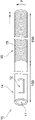
- the outer shape of the self-expandable stent 49 is schematically shown in FIG.
- the balloon 41 has a distal side fixing portion 42 fixed to the shaft 2, an expansion portion 43 not fixed to the shaft 2, and a proximity fixed to the shaft 2. It may have a position side fixing portion 44.
- the shaft 2 is composed of an inner tube 4 and an outer tube 5.
- the inner tube 4 extends from the distal end of the outer tube 5 and penetrates the balloon 41 in the longitudinal axis direction x of the shaft 2. Is preferable. As a result, the balloon 41 is joined to the shaft 2.
- the expansion portion 40 is a balloon 41
- a fluid feeder (not shown) is connected to the proximal portion of the shaft 2.
- the balloon 41 is configured such that a pressure fluid is supplied from the fluid feeder to the inside of the balloon 41 through the shaft 2.
- the balloon 41 expands, and when the pressure fluid is pulled out, the balloon 41 contracts.
- the outer surface of the balloon 41 comes into contact with the wall of a biological tube such as a blood vessel or a digestive tract, so that the shaft 2 can be fixed inside the body.
- the shaft 2 may have a plurality of lumens 3.
- the shaft 2 has a first lumen 3a through which a first tubular member 10, a second tubular member 20, and a light guide device 30 are inserted, and a second lumen 3b communicating with the inside of a balloon 41.
- the first lumen 3a having the above functions as an insertion passage for the light guide device 30, and the second lumen 3b functions as a passage for the pressure fluid.
- the shaft 2 is composed of an inner tube 4 and an outer tube 5
- the lumen of the inner tube 4 is the first lumen 3a
- the space between the inner tube 4 and the outer tube 5 is the second lumen 3b. good.
- the inflated portion 43 of the balloon 41 may have a straight pipe portion 43a and a tapered portion 43b formed in the distal portion and the proximal portion of the straight pipe portion 43a, respectively.
- the balloon 41 is preferably made of resin.
- the resin constituting the balloon 41 include polyamide-based resin, polyester-based resin, polyurethane-based resin, polyolefin-based resin, vinyl chloride-based resin, silicone-based resin, and natural rubber. Only one of these may be used, or two or more thereof may be used in combination. Of these, polyamide-based resins, polyester-based resins, and polyurethane-based resins are preferably used. An elastomer resin can be used from the viewpoint of thinning the balloon 41 and flexibility.
- the type of fluid supplied into the balloon 41 is not particularly limited, but for example, a liquid such as physiological saline, a contrast medium, or a mixed solution thereof, or a gas such as air, nitrogen, or carbon dioxide can be used. It is preferable that a gas is supplied into the balloon 41 in order to facilitate the transmission of the emitted light.
- the basket 45 is formed by binding a plurality of elastic wires 46 at a first binding portion and a second binding portion proximal to the first binding portion.
- the elastic wire 46 may be bent or spirally twisted between the first binding portion and the second binding portion.
- the basket is generally used for catching foreign substances such as stones, but in the device 1, it is used for fixing the position of the device 1 in the body.
- the elastic wire 46 is a wire having elasticity, and is preferably composed of a shape memory alloy or a shape memory resin.
- the elastic wire 46 is a single wire or twist made of, for example, stainless steel such as SUS304 or SUS316, platinum, nickel, cobalt, chromium, titanium, tungsten, aluminum, gold, silver, Ni—Ti alloy, Co—Cr alloy or the like. It may be a metal wire rod.
- the number of elastic wires 46 is not particularly limited and can be selected according to the inner diameter of the living tube wall and the like.
- the elastic wire is fixed to the shaft 2.
- Distal ends or proximal ends of the plurality of elastic wires 46 are arranged apart in the circumferential direction p, and the distal ends or proximal ends of the elastic wires are brazed or bonded to the shaft 2, or the elastic wires.
- the elastic wire can be fixed to the shaft 2 by covering the distal end portion or the proximal end portion of the above with a tubular connector and crimping the connector.
- the distal end of the elastic wire 46 is fixed to the shaft 2 by the first connector 47
- the proximal end of the elastic wire 46 is fixed to the shaft 2 by the second connector 48.
- the first connector 47 may also serve as the support portion 50.
- the stent is a structure that can be expanded in diameter and is composed of a mesh structure such as a mesh, and includes a plurality of columns. Stents can be formed from patterns of interconnected structural elements that stretch, for example, circumferentially and axially.
- the stent is a coil type made of one linear metal or polymer material, a type made by cutting out a metal tube or a tube made of a polymer material with a laser, etc., a type assembled by welding a linear part, Examples include a type made by weaving a plurality of linear metals.
- Stents can be classified into balloon expansion type and self-expansion type from the viewpoint of expansion mechanism.
- a stent is attached on the outer surface of the balloon and transported to the treatment site such as a lesion, and the stent is expanded at the treatment site using the balloon.
- the stent is transported to the lesion by a catheter having a member that suppresses expansion, and the stent expands by itself by removing the member that suppresses expansion at the treatment site.
- the stent is preferably a self-expanding stent. Since it is not necessary to provide a balloon inside the self-expanding type, the diameter in the reduced diameter state can be made smaller than that of the balloon expanding type.
- the description of the constituent material of the elastic wire 46 of the basket 45 can be referred to.
- the dilated portion 40 is a self-expandable stent 49 as shown in FIG. 13, it is preferable that the proximal end portion of the self-expandable stent 49 is fixed to the distal end portion of the shaft 2.
- the device 1 can be fixed in the body without the stent obstructing the emission of light.
- the distal end is not fixed to the distal end of the shaft 2.
- the shaft 2 can be fixed in the body by bringing the distal end of the stent into contact with the living tube wall.
- the stent can be fixed to the shaft 2 in the same manner as the elastic wire of the basket is fixed to the shaft 2.
- multiple struts are placed so as to be spaced apart in the circumferential direction p and brazed or glued to the shaft 2, or covered with a tubular connector over the proximal end of the struts.
- a method such as crimping the connector can be adopted.
- the device 1 When the expansion unit 40 is a basket or a stent, it is preferable that the device 1 further has a third tubular member (not shown) capable of accommodating the expansion unit 40 in the lumen.
- a third tubular member (not shown) capable of accommodating the expansion unit 40 in the lumen.
- the expansion portion 40 may be arranged at a position overlapping the non-existent portion 34 of the clad in the longitudinal axis direction x. As shown in FIG. 13, the extension portion 40 may be arranged distal to the non-existent portion 34 of the clad in the longitudinal axis direction x.
- the expansion portion 40 When the expansion portion 40 is provided at a position overlapping the non-existing portion 34 of the clad in the longitudinal axis direction x, it is preferable that the expansion portion 40 contains a light transmitting material. In that case, it is more preferable that both the portion of the shaft 2 covered by the expansion portion 40 and the expansion portion 40 are made of a light-transmitting material.
- the portion 34 When the portion 34 is located inside the expansion portion 40, the target tissue can be efficiently irradiated with light at the position corresponding to the balloon 41.
- the description of the shaft 2 can be referred to.
- the expansion portion 40 When the expansion portion 40 is provided at a position overlapping the non-existing portion 34 of the clad in the longitudinal axis direction x, it is preferable that the expansion portion 40 contains a light diffusing material. In that case, it is more preferable that both the portion of the shaft 2 covered by the expansion portion 40 and the expansion portion 40 are made of a light diffusing material. As a result, the target tissue can be evenly irradiated with light.
- the light diffusing material the description of the material of the shaft 2 can be referred to.
- a support portion 50 for supporting the distal portion of the light guide device 30 is further provided at the distal end portion of the shaft 2.
- the support portion 50 can suppress the hanging of the distal portion of the light guide device 30 due to gravity. As a result, it becomes easy to perform the rotation operation of the first tubular member 10, the rotation operation of the second tubular member 20, and the movement operation of the light guide device 30 in the longitudinal axis direction x.
- the support portion 50 may be provided outside the radial direction y of the shaft 2, or may be arranged in the lumen 3 of the shaft 2 as shown in FIG. .. In order to reliably support the light guide device 30 with the support portion 50, a part of the support portion 50 may be arranged on the distal side of the distal end 2a of the shaft 2 as shown in FIG.
- the support portion 50 can be formed in a cylindrical shape. As shown in FIG. 13, the cylindrical support portion 50 may have a constant inner diameter in the longitudinal axis direction x. As shown in FIGS. 1 and 2, the cylindrical support portion 50 may have a different inner diameter depending on the position in the longitudinal axis direction x. For example, the tubular support portion 50 is located on the distal side of the large diameter portion 51 that supports the shaft 2 and the large diameter portion 51 to support the light guide device 30 and is larger than the large diameter portion 51. It may have a small diameter portion 52 having a small inner diameter. As a result, the effect of suppressing the sagging of the light guide device 30 due to gravity can be further enhanced. For the same reason, the tubular support portion 50 may be formed in a tapered shape in which the inner diameter decreases toward the distal side.
- the description of the material constituting the shaft 2 can be referred to.
- the distal end 50a of the support portion 50 is from the distal end 40a of the expansion portion 40. Is preferably located on the distal side. Further, as shown in FIG. 13, when the expansion portion 40 is located distal to the non-existent portion 34 of the clad in the longitudinal direction x, the distal end 50a of the support portion 50 is far from the expansion portion 40. It may be located proximal to the position end 40a.
- Each member constituting the device 1 may be provided with a radiation opaque marker.
- the first marker 61 may be arranged at the distal portion of the shaft 2.
- the position of the shaft 2 can be specified under fluoroscopy, so that the shaft 2 can be aligned with the position of the tissue to be irradiated.
- the second marker 62 may be arranged on the protective cylinder 36 on the distal side of the distal end of the core 32.
- the third marker 63 may be arranged on the protective cylinder 36 on the proximal side of the proximal end of the non-existent portion 34 of the clad.
- the radiation opaque markers are arranged on both sides of the non-existent portion 34 of the clad that becomes the light emitting area in the longitudinal axis direction of the protective cylinder 36, so that the position of the light emitting area can be more easily specified under fluoroscopy.
- a fourth marker 64 may be further arranged on the proximal side of the shaft 2 with respect to the first marker 61. This makes it easier to identify the position of the longitudinal axis direction x under fluoroscopy.
- the fifth marker 65 is arranged at the distal portion of the first tubular member 10, and it is more preferable that the fifth marker 65 is arranged on the distal side of the first window 12. Further, it is preferable that the sixth marker 66 is arranged at the distal portion of the first tubular member 10 and proximal to the first window 12. This makes it easier to grasp the position of the first window 12 in the longitudinal axis direction of the first tubular member 10, and thus makes it easier to specify the position of the light emitting area under fluoroscopy.
- the seventh marker 67 is arranged at the distal portion of the second tubular member 20, and it is more preferable that the seventh marker 67 is arranged on the distal side of the second window 22. Further, the eighth marker 68 may be arranged at the distal portion of the second tubular member 20 and proximal to the second window 22. This makes it easier to grasp the position of the second window 22 in the longitudinal axis direction of the second tubular member 20.
- the distal end of the second marker 62 and the fifth marker are arranged in order from the distal side to the proximal side. It is preferred that the distal end of the marker 65, the distal end of the seventh marker 67, and the distal end of the first marker 61 are located. By locating the markers in this way, it becomes easy to grasp the positions of the shaft 2, the non-existent portion 34 of the clad, and the first window 12.
- the third marker 63 is sequentially provided from the proximal side to the distal side for the same reason as described above. It is preferable that the proximal end of the marker 66, the proximal end of the sixth marker 66, the proximal end of the eighth marker 68, and the proximal end of the fourth marker 64 are located.
- the shape of the marker is not particularly limited and may be annular or rod-shaped.
- the marker may have a coil shape or may have a C-shaped cross section having a slit in the ring. If the marker is annular or coiled, it will be easier to attach the marker. When the marker is rod-shaped or coil-shaped, it becomes easy to place the marker in the lumen of each member.
- the marker is preferably composed of a material containing a metal material such as platinum, gold, silver, tungsten, tantalum, iridium, palladium and alloys thereof.
- the marker may be a metal marker composed of the above-mentioned metal material, or may be a resin marker composed of the above-mentioned metal material.
Landscapes
- Health & Medical Sciences (AREA)
- Engineering & Computer Science (AREA)
- Life Sciences & Earth Sciences (AREA)
- Biomedical Technology (AREA)
- Veterinary Medicine (AREA)
- Animal Behavior & Ethology (AREA)
- General Health & Medical Sciences (AREA)
- Public Health (AREA)
- Anesthesiology (AREA)
- Pulmonology (AREA)
- Heart & Thoracic Surgery (AREA)
- Hematology (AREA)
- Biophysics (AREA)
- Pathology (AREA)
- Nuclear Medicine, Radiotherapy & Molecular Imaging (AREA)
- Radiology & Medical Imaging (AREA)
- Radiation-Therapy Devices (AREA)
Priority Applications (1)
| Application Number | Priority Date | Filing Date | Title |
|---|---|---|---|
| JP2022566781A JPWO2022118559A1 (https=) | 2020-12-01 | 2021-10-21 |
Applications Claiming Priority (2)
| Application Number | Priority Date | Filing Date | Title |
|---|---|---|---|
| JP2020199449 | 2020-12-01 | ||
| JP2020-199449 | 2020-12-01 |
Publications (1)
| Publication Number | Publication Date |
|---|---|
| WO2022118559A1 true WO2022118559A1 (ja) | 2022-06-09 |
Family
ID=81853108
Family Applications (1)
| Application Number | Title | Priority Date | Filing Date |
|---|---|---|---|
| PCT/JP2021/038866 Ceased WO2022118559A1 (ja) | 2020-12-01 | 2021-10-21 | 光照射医療装置 |
Country Status (2)
| Country | Link |
|---|---|
| JP (1) | JPWO2022118559A1 (https=) |
| WO (1) | WO2022118559A1 (https=) |
Cited By (2)
| Publication number | Priority date | Publication date | Assignee | Title |
|---|---|---|---|---|
| WO2024177102A1 (ja) * | 2023-02-21 | 2024-08-29 | 古河電気工業株式会社 | 光拡散装置 |
| WO2025070318A1 (ja) * | 2023-09-28 | 2025-04-03 | テルモ株式会社 | 光照射デバイス |
Citations (8)
| Publication number | Priority date | Publication date | Assignee | Title |
|---|---|---|---|---|
| JPH01135901U (https=) * | 1988-03-11 | 1989-09-18 | ||
| US5409483A (en) * | 1993-01-22 | 1995-04-25 | Jeffrey H. Reese | Direct visualization surgical probe |
| JPH0736101U (ja) * | 1993-12-20 | 1995-07-04 | 株式会社モリテックス | 光ファイバレーザ導光拡散プローブ |
| JPH10286309A (ja) * | 1997-04-15 | 1998-10-27 | Terumo Corp | 医療用チューブ |
| JPH11509436A (ja) * | 1995-06-07 | 1999-08-24 | アベラ レーザー システムズ,インコーポレイテッド | 光ファイバーカテーテルおよびその方法 |
| JP2001505443A (ja) * | 1996-05-17 | 2001-04-24 | キュウエルティー フォトセラピュウティクス,インコーポレイテッド | 光力学治療のためのバルーンカテーテル |
| JP2005237827A (ja) * | 2004-02-27 | 2005-09-08 | Terumo Corp | 治療用カテーテルおよび治療装置 |
| WO2020144799A1 (ja) * | 2019-01-10 | 2020-07-16 | オリンパス株式会社 | 光治療装置 |
-
2021
- 2021-10-21 WO PCT/JP2021/038866 patent/WO2022118559A1/ja not_active Ceased
- 2021-10-21 JP JP2022566781A patent/JPWO2022118559A1/ja active Pending
Patent Citations (8)
| Publication number | Priority date | Publication date | Assignee | Title |
|---|---|---|---|---|
| JPH01135901U (https=) * | 1988-03-11 | 1989-09-18 | ||
| US5409483A (en) * | 1993-01-22 | 1995-04-25 | Jeffrey H. Reese | Direct visualization surgical probe |
| JPH0736101U (ja) * | 1993-12-20 | 1995-07-04 | 株式会社モリテックス | 光ファイバレーザ導光拡散プローブ |
| JPH11509436A (ja) * | 1995-06-07 | 1999-08-24 | アベラ レーザー システムズ,インコーポレイテッド | 光ファイバーカテーテルおよびその方法 |
| JP2001505443A (ja) * | 1996-05-17 | 2001-04-24 | キュウエルティー フォトセラピュウティクス,インコーポレイテッド | 光力学治療のためのバルーンカテーテル |
| JPH10286309A (ja) * | 1997-04-15 | 1998-10-27 | Terumo Corp | 医療用チューブ |
| JP2005237827A (ja) * | 2004-02-27 | 2005-09-08 | Terumo Corp | 治療用カテーテルおよび治療装置 |
| WO2020144799A1 (ja) * | 2019-01-10 | 2020-07-16 | オリンパス株式会社 | 光治療装置 |
Cited By (2)
| Publication number | Priority date | Publication date | Assignee | Title |
|---|---|---|---|---|
| WO2024177102A1 (ja) * | 2023-02-21 | 2024-08-29 | 古河電気工業株式会社 | 光拡散装置 |
| WO2025070318A1 (ja) * | 2023-09-28 | 2025-04-03 | テルモ株式会社 | 光照射デバイス |
Also Published As
| Publication number | Publication date |
|---|---|
| JPWO2022118559A1 (https=) | 2022-06-09 |
Similar Documents
| Publication | Publication Date | Title |
|---|---|---|
| JP7408670B2 (ja) | 光照射医療装置 | |
| JP7384814B2 (ja) | 光照射医療装置 | |
| JP6879945B2 (ja) | カテーテル | |
| KR20030037233A (ko) | 방사선 치료용 카테테르 | |
| WO2022118559A1 (ja) | 光照射医療装置 | |
| JP7308123B2 (ja) | 光照射デバイス、及び、光照射システム | |
| JP2025532186A (ja) | 修復機能を有するバルーンカテーテルシステム | |
| WO2021019981A1 (ja) | カテーテル、及び、光照射システム | |
| US12434071B2 (en) | Light irradiation medical device | |
| JP7807328B2 (ja) | 光照射医療装置 | |
| JP7807329B2 (ja) | 光照射医療装置 | |
| WO2023047711A1 (ja) | 光照射医療装置 | |
| JP7687889B2 (ja) | 光照射医療装置 | |
| JP7718934B2 (ja) | 光照射医療装置 | |
| WO2022158075A1 (ja) | 光照射医療装置 | |
| JPH11188099A (ja) | バルーンカテーテル | |
| WO2023047709A1 (ja) | 光照射医療装置 | |
| WO2023281918A1 (ja) | 光照射医療装置 | |
| WO2022181133A1 (ja) | 内視鏡用光照射装置 | |
| JP2024136905A (ja) | 光照射医療装置 | |
| WO2023281917A1 (ja) | 光照射医療装置 | |
| JP2024136907A (ja) | 光照射医療装置 | |
| JP2025058699A (ja) | 光照射デバイス | |
| WO2025070409A1 (ja) | バルーン、光照射デバイス及び治療方法 | |
| WO2025028183A1 (ja) | カテーテル |
Legal Events
| Date | Code | Title | Description |
|---|---|---|---|
| 121 | Ep: the epo has been informed by wipo that ep was designated in this application |
Ref document number: 21900315 Country of ref document: EP Kind code of ref document: A1 |
|
| ENP | Entry into the national phase |
Ref document number: 2022566781 Country of ref document: JP Kind code of ref document: A |
|
| NENP | Non-entry into the national phase |
Ref country code: DE |
|
| 122 | Ep: pct application non-entry in european phase |
Ref document number: 21900315 Country of ref document: EP Kind code of ref document: A1 |