WO2022113634A1 - 鉛蓄電池 - Google Patents
鉛蓄電池 Download PDFInfo
- Publication number
- WO2022113634A1 WO2022113634A1 PCT/JP2021/039831 JP2021039831W WO2022113634A1 WO 2022113634 A1 WO2022113634 A1 WO 2022113634A1 JP 2021039831 W JP2021039831 W JP 2021039831W WO 2022113634 A1 WO2022113634 A1 WO 2022113634A1
- Authority
- WO
- WIPO (PCT)
- Prior art keywords
- electrode plate
- negative electrode
- group
- lead
- polymer compound
- Prior art date
- Legal status (The legal status is an assumption and is not a legal conclusion. Google has not performed a legal analysis and makes no representation as to the accuracy of the status listed.)
- Ceased
Links
Images

Classifications
-
- H—ELECTRICITY
- H01—ELECTRIC ELEMENTS
- H01M—PROCESSES OR MEANS, e.g. BATTERIES, FOR THE DIRECT CONVERSION OF CHEMICAL ENERGY INTO ELECTRICAL ENERGY
- H01M10/00—Secondary cells; Manufacture thereof
- H01M10/06—Lead-acid accumulators
- H01M10/12—Construction or manufacture
-
- H—ELECTRICITY
- H01—ELECTRIC ELEMENTS
- H01M—PROCESSES OR MEANS, e.g. BATTERIES, FOR THE DIRECT CONVERSION OF CHEMICAL ENERGY INTO ELECTRICAL ENERGY
- H01M4/00—Electrodes
- H01M4/02—Electrodes composed of, or comprising, active material
- H01M4/14—Electrodes for lead-acid accumulators
-
- H—ELECTRICITY
- H01—ELECTRIC ELEMENTS
- H01M—PROCESSES OR MEANS, e.g. BATTERIES, FOR THE DIRECT CONVERSION OF CHEMICAL ENERGY INTO ELECTRICAL ENERGY
- H01M4/00—Electrodes
- H01M4/02—Electrodes composed of, or comprising, active material
- H01M4/62—Selection of inactive substances as ingredients for active masses, e.g. binders, fillers
-
- Y—GENERAL TAGGING OF NEW TECHNOLOGICAL DEVELOPMENTS; GENERAL TAGGING OF CROSS-SECTIONAL TECHNOLOGIES SPANNING OVER SEVERAL SECTIONS OF THE IPC; TECHNICAL SUBJECTS COVERED BY FORMER USPC CROSS-REFERENCE ART COLLECTIONS [XRACs] AND DIGESTS
- Y02—TECHNOLOGIES OR APPLICATIONS FOR MITIGATION OR ADAPTATION AGAINST CLIMATE CHANGE
- Y02E—REDUCTION OF GREENHOUSE GAS [GHG] EMISSIONS, RELATED TO ENERGY GENERATION, TRANSMISSION OR DISTRIBUTION
- Y02E60/00—Enabling technologies; Technologies with a potential or indirect contribution to GHG emissions mitigation
- Y02E60/10—Energy storage using batteries
Definitions
- the present invention relates to a lead storage battery.
- Lead-acid batteries are used for various purposes such as in-vehicle use, industrial use, and so on.
- Lead-acid batteries include a negative electrode plate, a positive electrode plate, a separator (or mat), an electrolytic solution, and the like.
- Each electrode plate comprises a current collector and an electrode material.
- Additives may be added to the constituent members of the lead-acid battery from the viewpoint of imparting various functions.
- Patent Document 1 an aqueous emulsion of silicone is impregnated into an electrode obtained by filling a support with a kneaded product of an active material obtained by adding and kneading a dispersion of a fluororesin to form fibers of the fluororesin.
- a method for manufacturing an electrode for a lead storage battery, which comprises a step and a step of drying next, is described.
- Patent Document 2 describes a plate in which a paste containing lead oxide, dilute sulfuric acid, and water as main components is filled in a lattice, and then the paste before aging and drying has plasticity.
- a method for manufacturing a closed-type lead-acid battery which comprises using an electrode plate whose surface is smoothed by pressing while spraying an aqueous solution of silica powder.
- Patent Document 2 proposes that the average roughness of the surface of the electrode plate after pressing is 50 ⁇ m or less.
- Lead-acid batteries may be used in an undercharged state called a partially charged state (PSOC).
- PSOC partially charged state
- lead-acid batteries mounted on vehicles controlled by idling stop (IS) are used in PSOC.
- IS idling stop
- stratification tends to proceed in which the specific gravity of the electrolytic solution in the upper part of the battery is gradually lowered and the specific gravity of the electrolytic solution in the lower part of the battery is gradually increased.
- lead sulfate accumulates significantly in the lower part of the negative electrode plate, and sulfation in which lead sulfate crystals are formed is likely to occur.
- the capacity is reduced, and the electrode plate is deteriorated due to the non-uniform charge / discharge reaction, so that the life of the lead storage battery is shortened.
- One aspect of the present invention includes a electrode plate group, an electrolytic solution, and an electric tank for accommodating the electrode plate group and the electrolytic solution, and the electrode plate group includes a positive electrode plate, a negative electrode plate, and a positive electrode plate.
- a separator interposed between the electrode plate and the negative electrode plate is provided, and the withdrawal load when the electrode plate group is pulled out from the electric tank is 1.5 times or more the own weight of the electrode plate group, and the negative electrode plate is provided.
- the surface roughness is 0.4 mm or less
- the negative electrode plate contains a negative electrode material
- the negative electrode material contains a polymer compound
- the polymer compound is measured using heavy chloroform as a solvent.
- the present invention relates to a lead storage battery having a peak in the range of 3.2 ppm or more and 3.8 ppm or less in the chemical shift of the NMR spectrum.
- Another aspect of the present invention includes a electrode plate group, an electrolytic solution, and an electric tank for accommodating the electrode plate group and the electrolytic solution, and the electrode plate group includes a positive electrode plate, a negative electrode plate, and a positive electrode.
- a separator interposed between the plate and the negative electrode plate is provided, and the pull-out load when the electrode plate group is pulled out from the electric tank is 1.5 times or more the own weight of the electrode plate group, and the negative electrode plate is used.
- the surface roughness of the negative electrode plate is 0.4 mm or less, the negative electrode plate contains a negative electrode material, the negative electrode material contains a polymer compound, and the polymer compound has a repeating structure of an oxyC 2-4 alkylene unit.
- the lead storage battery that has.
- the lead-acid battery according to the embodiment of the present invention includes a plate group, an electrolytic solution, and an electric tank for accommodating the electrode plate group and the electrolytic solution.
- the electrode plate group includes a positive electrode plate, a negative electrode plate, and a separator interposed between the positive electrode plate and the negative electrode plate.
- the negative electrode plate contains the negative electrode material.
- the positive electrode plate contains a positive electrode material. Each electrode material of the negative electrode material and the positive electrode material is usually held in the current collector.
- the electrode material is a plate from which the current collector is removed. Members such as mats and pacing papers may be attached to the electrode plate. Since such a member (also referred to as a sticking member) is used integrally with the plate, it is included in the plate. When the electrode plate includes a sticking member (mat, pacing paper, etc.), the electrode material excludes the current collector and the sticking member.
- the negative electrode material contains a polymer compound.
- the polymer compound has a peak in the range of 3.2 ppm or more and 3.8 ppm or less in the chemical shift of 1 H-NMR spectrum measured using deuterated chloroform as a solvent.
- the polymer compound may have a repeating structure of oxyC 2-4 alkylene units. In the above 1 H-NMR spectrum, the peak appearing in the chemical shift range of 3.2 ppm or more and 3.8 ppm or less is derived from the oxyC 2-4 alkylene unit.
- the polymer compound By including the polymer compound in the negative electrode material, it is expected that the amount of overcharge electricity (reduced amount) will be reduced.
- the reason is as follows. First, the polymer compound tends to have a linear structure, and the lead surface in the negative electrode electrode material is thinly and widely covered with the polymer compound. Since the polymer compound contained in the negative electrode electrode material is present in the vicinity of lead, it is considered that the oxyC 2-4 alkylene unit exhibits a high adsorptive action on lead. It is considered that the hydrogen overvoltage rises by covering a wide area of the lead surface with the polymer compound, hydrogen generation is less likely to occur during overcharging, and the liquid reduction can be reduced. In order to effectively exert the effect of the polymer compound, it is important that the negative electrode material contains the polymer compound regardless of whether or not the components of the lead storage battery other than the negative electrode material contain the polymer compound. Is.
- the polymer compound is eluted from the negative electrode material, the effect of suppressing the amount of overcharge electricity (reduced amount) is reduced. Even if the amount of the polymer compound added to the negative electrode material is increased, the amount of the polymer compound eluted from the negative electrode material increases, so that the effect of suppressing the amount of overcharged electricity (reduced amount) can be sufficiently restored. Have difficulty.
- the pull-out load when the electrode plate group is pulled out from the electric tank (hereinafter, simply referred to as “pull-out load”) is 1.5 times or more the own weight of the electrode plate group, and the surface roughness of the negative electrode plate is 0.
- the cycle life of the lead storage battery can be remarkably improved while suppressing the amount of overcharged electricity (reduced amount) even when used in PSOC.
- the pull-out load is 1.5 times or more the own weight of the electrode plate group and the surface roughness of the negative electrode plate is 0.4 mm or less, stratification is remarkably suppressed and the negative electrode material is used. It is considered that the elution of the polymer compound is remarkably suppressed.
- the polymer compound is contained in the negative electrode material, stratification can be suppressed only slightly if the pull-out load is 1.5 times or more the own weight of the electrode plate group, and the polymer compound is electrolyzed. It is also difficult to suppress elution into the liquid. Normally, the surface of the negative electrode plate has considerable unevenness, so even if the withdrawal load is increased, the degree of adhesion between the separator and the negative electrode plate is low, and it is not possible to suppress the stratification of the electrolytic solution and the elution of the polymer compound. It is enough.
- the elution and oxidative decomposition of the polymer compound are promoted, the charge acceptability is lowered, and the cycle life is remarkably shortened. Further, since the polymer compound elutes from the negative electrode material, the effect of reducing the amount of overcharge electricity is reduced.
- the unevenness of the surface of the negative electrode plate is formed in the manufacturing process of the negative electrode plate.
- the negative electrode paste is pressed against the negative electrode current collector by a predetermined jig from the viewpoint of facilitating the filling.
- irregularities are formed on the surface of the negative electrode electrode material, and a negative electrode plate having a surface roughness of more than 0.4 mm is formed.
- the negative electrode material contains the polymer compound
- simply setting the surface roughness of the negative electrode plate to 0.4 mm or less does not have the effect of suppressing stratification, and elution of the polymer compound into the electrolytic solution is not possible. It is also difficult to suppress. Even if the surface roughness of the negative electrode plate is reduced without increasing the pull-out load, the degree of adhesion between the separator and the negative electrode plate cannot be increased, and it is not possible to suppress the stratification of the electrolytic solution and the elution of the polymer compound. It is enough.
- the pull-out load may be 1.5 times or more of its own weight, but preferably 1.8 times or more, 2.8 times or more, or 3.5 times or more. Since it is difficult to manufacture the pull-out load to be 10 times or more of its own weight, the upper limit of the pull-out load is 10 times its own weight.
- the surface roughness of the negative electrode plate may be 0.4 mm or less, but may be 0.3 mm or less, 0.2 mm or less, or 0.15 mm or less.
- the lead-acid battery may be either a control valve type (sealed type) lead-acid battery (VRLA) or a liquid type (vent type) lead-acid battery.
- the pull-out load when pulling out the electrode plate group from the electric tank, the surface roughness of the negative electrode plate, and the content of the polymer compound in the negative electrode electrode material are the lead-acid battery in a fully charged state and the electrode taken out from the lead-acid battery, respectively. It is required for the negative electrode plate in the plate group.
- the fully charged state of a liquid lead-acid battery is defined by the definition of JIS D 5301: 2019. More specifically, in a water tank at 25 ° C ⁇ 2 ° C, charging is performed every 15 minutes with a current (A) 0.2 times the value described as the rated capacity (value whose unit is Ah). The state in which the lead-acid battery is charged is regarded as a fully charged state until the terminal voltage (V) of No. 1 or the electrolyte density converted into temperature at 20 ° C. shows a constant value with three valid digits three times in a row.
- V terminal voltage
- the fully charged state is 0.2 times the current (value with Ah as the unit) described in the rated capacity in the air tank at 25 ° C ⁇ 2 ° C (the unit is Ah).
- A) constant current constant voltage charging of 2.23 V / cell is performed, and the charging current at the time of constant voltage charging is 0.005 times the value (value with the unit being Ah) described in the rated capacity (A). When it becomes, charging is completed.
- a fully charged lead-acid battery is a fully charged lead-acid battery.
- the lead-acid battery may be fully charged after the chemical conversion, immediately after the chemical conversion, or after a lapse of time from the chemical conversion (for example, after the chemical conversion, the lead-acid battery in use (preferably at the initial stage of use) is fully charged. May be).
- An initial use battery is a battery that has not been used for a long time and has hardly deteriorated.
- the self-weight of the electrode plate group is measured by the following procedure. First, after cutting the top lid of the lead-acid battery and disassembling the lead-acid battery, all the electrolytic solution in the battery case is drained, and the electrode plate group is taken out. Next, the weight (W1) of the taken-out electrode plate group is measured using a scale in a state where the electrolytic solution is soaked (the electrode plate is wet). In this way, the self-weight (W1) of the electrode plate group is measured.
- the electrode plate group for measuring its own weight includes a positive electrode plate, a negative electrode plate, and other components of the electrode plate group (for example, a separator and a strap).
- ⁇ Pull-out load> The pull-out load when pulling out the electrode plate group from the electric tank is measured by the following procedure. First, the electrode plate group whose own weight is measured as described above is returned to the electric tank, and a hook is hooked on a part of the electrode plate group (for example, the strap portion) to pull out the electrode plate group. At this time, the load when the electrode plate group is pulled out from the electric tank is measured by using the digital force gauge. The maximum value of the measured load is taken as the pull-out load (W2) of the electrode plate group. Then, the ratio of the pull-out load (W2) to the own weight (W1) of the electrode plate group (hereinafter, also referred to as “pull-out load ratio”) is obtained.
- ⁇ Surface roughness of negative electrode plate> It is measured by the following procedure. First, the electrode plate group taken out from the fully charged lead storage battery as described above is disassembled, and the negative electrode plate is taken out. The obtained negative electrode plate is washed with water to remove sulfuric acid from the negative electrode plate. Wash with water by pressing the pH test paper against the surface of the negative electrode plate washed with water until it is confirmed that the color of the test paper does not change. However, the time for washing with water shall be within 2 hours. The negative electrode plate washed with water is dried at 60 ⁇ 5 ° C. for about 6 hours in a reduced pressure environment. If the negative electrode plate contains a sticking member, the surface roughness is measured without removing the sticking member.
- the shape of the negative electrode plate 3 is generally quadrangular, and the first side 31 and the second side 32 facing each other and the third side 33 and the fourth side intersecting with each other and facing each other are formed. With 34.
- the portion of the negative electrode plate 3 having the negative electrode material is formed by two straight lines L1 and L2 extending from the third side toward the fourth side and two straight lines L3 extending from the first side toward the second side.
- L4 divides into 9 sections of 3 rows x 3 columns of approximately the same size.
- the maximum height roughness Rz is measured in a rectangular region of 5 mm ⁇ 7.5 mm (the short side is parallel to L1 and L2, and the long side is parallel to L3 and L4) A1 to A9 in the center of each section.
- the maximum height roughness Rz means the difference (Rv + Rp) from the most concave part (maximum valley depth Rv) to the most protruding part (maximum mountain height Rp).
- the maximum height roughness Rz is measured with a microscope (for example, VK-X100 series manufactured by KEYENCE CORPORATION).
- the surface roughness of the negative electrode plate is obtained as the average value of 18 maximum height roughness Rz measured on both sides of A1 to A9.
- the electrode plate group has two or more negative electrode plates
- at least one negative electrode plate may satisfy the above conditions.
- the ratio of the negative electrode plates satisfying the above conditions is 100% or less. It is preferable that all of the negative electrode plates included in the electrode plate group satisfy the above conditions.
- the lead storage battery has two or more plate groups
- at least one plate group may satisfy the above conditions.
- 50% or more (more preferably 80% or more or 90% or more) of the number of electrode plates contained in the lead storage battery satisfies the above conditions.
- the electrode plate groups contained in the lead storage battery the ratio of the electrode plate group satisfying the above conditions is 100% or less. It is preferable that all of the electrode plates included in the lead-acid battery satisfy the above conditions.
- the negative electrode plate usually includes a negative electrode current collector in addition to the negative electrode material.
- the negative electrode plate can be formed by applying or filling a negative electrode paste to a negative electrode current collector, aging and drying to produce an unchemical negative electrode plate, and then forming an unchemical negative electrode plate.
- the negative electrode paste is prepared, for example, by kneading lead powder, a polymer compound, other additives if necessary, water and sulfuric acid (or an aqueous solution of sulfuric acid).
- the unchemical negative electrode plate may be aged at a temperature higher than room temperature and a high humidity.
- the negative electrode paste When applying or filling the negative electrode paste to the negative electrode current collector, press the negative electrode paste against the negative electrode collector with a jig that has as little unevenness as possible so that the surface roughness of the negative electrode plate is 0.4 mm or less. do. Thereby, the surface roughness of the negative electrode electrode material can be controlled to 0.4 mm or less.
- the method for controlling the surface roughness is not particularly limited, and for example, the surface roughness of the ripened negative electrode plate after aging may be polished to control the surface roughness.
- Chemical formation can be performed by charging the electrode plate group in a state where the electrode plate group including the unchemical negative electrode plate is immersed in the electrolytic solution containing sulfuric acid in the electric tank of the lead storage battery. However, the chemical formation may be performed before assembling the lead-acid battery or the electrode plate group. The formation produces spongy lead.
- the negative electrode current collector may be formed by casting lead (Pb) or a lead alloy, or may be formed by processing a lead sheet or a lead alloy sheet. Examples of the processing method include expanding processing and punching processing. It is preferable to use a grid-shaped current collector as the negative electrode current collector because it is easy to support the negative electrode material.
- the lead alloy used for the negative electrode current collector may be any of Pb—Sb-based alloys, Pb-Ca-based alloys, and Pb-Ca—Sn-based alloys. These leads or lead alloys may further contain, as an additive element, at least one selected from the group consisting of Ba, Ag, Al, Bi, As, Se, Cu and the like.
- the negative electrode current collector may include a surface layer. The surface layer and the inner layer of the negative electrode current collector may have different compositions. The surface layer may be formed on a part of the negative electrode current collector. The surface layer may be formed on the selvage portion of the negative electrode current collector. The surface layer of the selvage portion may contain Sn or a Sn alloy.
- the negative electrode electrode material contains a negative electrode active material (specifically, lead or lead sulfate) and a polymer compound that develop a capacity by a redox reaction.
- the negative electrode material may further contain an additive. Examples of the additive include, but are not limited to, an organic shrinkage proofing agent, a carbonaceous material, and barium sulfate.
- the negative electrode active material in the charged state is spongy lead.
- the polymer compound satisfies at least one of the following conditions (i) and (ii).
- Condition (i) The polymer compound has a peak in the range of 3.2 ppm or more and 3.8 ppm or less in the chemical shift of 1 H-NMR spectrum measured using deuterated chloroform as a solvent.
- Condition (ii) The polymer compound comprises a repeating structure of oxyC 2-4 alkylene units.
- the oxy-C 2-4 alkylene unit is a unit represented by -O-R1- (R1 represents a C 2-4 alkylene group).
- condition (i) the peak of 3.2 ppm or more and 3.8 ppm or less is derived from the oxyC 2-4 alkylene unit. That is, the polymer compound satisfying the condition (ii) is also a polymer compound satisfying the condition (i). However, the polymer compound satisfying the condition (i) may contain a repeating structure of a monomer unit other than the oxyC 2-4 alkylene unit, and may have a certain molecular weight.
- the number average molecular weight (Mn) of the polymer compound satisfying the above (i) or (ii) may be, for example, 300 or more.
- the polymer compound may contain an oxygen atom attached to a terminal group and an -CH 2 -group and / or -CH ⁇ group attached to the oxygen atom.
- the ratio to the total of the integrated value of the peak of the hydrogen atom of -CH ⁇ group bonded to is, for example, 50% or more, 80% or more, 85% or more, or 90% or more.
- Such polymer compounds contain a large amount of oxyC 2-4 alkylene unit in the molecule.
- the polymer compound is more likely to have a linear structure and is easier to cover the lead surface thinly. Therefore, the liquid reduction can be reduced more effectively.
- the polymer compound has a -OH group at the end and has a -CH 2 -group or -CH ⁇ group bonded to the oxygen atom of this -OH group, 1 -CH 2 -group in the H-NMR spectrum.
- the peak of the hydrogen atom of the -CH ⁇ group has a chemical shift in the range of more than 3.8 ppm and 4.0 ppm or less.
- the polymer compound preferably contains a repeating structure of oxyC 2-4 alkylene units.
- a polymer compound containing a repeating structure of an oxyC 2-4 alkylene unit it is considered that the polymer compound is more easily adsorbed to lead and easily has a linear structure, so that the lead surface can be easily covered thinly.
- the repeating structure may contain one type of oxyC 2-4 alkylene unit, or may contain two or more types of oxy C 2-4 alkylene unit.
- Polymer compounds having a repeating structure of oxyC 2-4 alkylene units also include those classified as surfactants (eg, nonionic surfactants).
- the oxyC 2-4 alkylene unit includes an oxyethylene unit, an oxypropylene unit, an oxytrimethylene unit, an oxy2-methyl-1,3-propylene unit, an oxy1,4-butylene unit, and an oxy1,3-butylene unit. And so on.
- the polymer compound may have one kind of such oxyC 2-4 alkylene unit, or may have two or more kinds.
- the oxyC 2-4 alkylene unit may be, for example, an oxypropylene unit (-O-CH (-CH 3 ) -CH 2- ). That is, the polymer compound may contain a repeating structure of oxypropylene units. Such polymer compounds have high adsorptivity to lead, but do not adhere excessively to the lead surface. Therefore, the liquid reduction can be effectively reduced.
- the oxyC 2-4 alkylene unit may be, for example, an oxyethylene unit (-O-CH 2 -CH 2- ). That is, the polymer compound may contain a repeating structure of oxyethylene units. Since the repeating structure of the oxyethylene unit has high hydrophilicity, it can be selectively adsorbed to lead. Therefore, it becomes easy to control the adsorptivity of the polymer compound to lead.
- the polymer compound is at least selected from the group consisting of a hydroxy compound having a repeating structure of an oxyC 2-4 alkylene unit (hereinafter, also referred to as hydroxy compound C), an etherified product of the hydroxy compound C, and an esterified product of the hydroxy compound C. It may contain one kind.
- the hydroxy compound C is selected from the group consisting of a poly C 2-4 alkylene glycol, a copolymer containing a repeating structure of an oxy C 2-4 alkylene unit, and a poly C 2-4 alkylene oxide adduct of a polyol. It may be at least one kind. When such a polymer compound is used, liquid reduction can be suppressed more effectively.
- Examples of the copolymer containing the repeating structure of the oxyC 2-4 alkylene unit include a copolymer containing different oxy C 2-4 alkylene units, a poly C 2-4 alkylene glycol alkyl ether, and a carboxylic acid poly C 2-4 . Examples thereof include alkylene glycol esters.
- the copolymer may be a block copolymer.
- Examples of the polyol constituting the poly C 2-4 alkylene oxide adduct of the polyol include an aliphatic polyol, an alicyclic polyol, an aromatic polyol, and a heterocyclic polyol.
- Aliphatic polyols, alicyclic polyols (for example, polyhydroxycyclohexane, polyhydroxynorbornane, etc.) and the like are preferable, and aliphatic polyols are particularly preferable because the polymer compound is thin and easily spreads on the lead surface.
- Examples of the aliphatic polyol include an aliphatic diol and a polyol having more than triol (for example, glycerin, trimethylolpropane, pentaerythritol, sugar or sugar alcohol).
- Examples of the aliphatic diol include alkylene glycols having 5 or more carbon atoms.
- the alkylene glycol may be, for example, C 5-14 alkylene glycol or C 5-10 alkylene glycol.
- Examples of the sugar or sugar alcohol include sucrose, erythritol, xylitol, mannitol, sorbitol and the like.
- the sugar or sugar alcohol may have either a chain structure or a cyclic structure.
- the alkylene oxide corresponds to the oxyC 2-4 alkylene unit of the polymer compound and comprises at least C 2-4 alkylene oxide.
- the polyol is preferably a diol.
- -OH groups (-OH groups composed of a hydrogen atom of the terminal group and an oxygen atom bonded to this hydrogen atom) at least a part of the terminal of hydroxy compound C are etherified.
- -Has an OR2 group (in the formula, R2 is an organic group).
- R2 is an organic group.
- ends of the polymer compound some ends may be etherified, or all ends may be etherified.
- one end of the main chain of the linear polymer compound may be a —OH group and the other end may be a —OR2 group.
- R3 is an organic group.
- some ends may be esterified or all ends may be esterified.
- Examples of the organic groups R2 and R3 include hydrocarbon groups.
- the hydrocarbon group may have a substituent (hydroxy group, alkoxy group, carboxy group, etc.).
- the hydrocarbon group may be any of an aliphatic, alicyclic and aromatic group.
- the aromatic hydrocarbon group and the alicyclic hydrocarbon group may have an aliphatic hydrocarbon group (alkyl group, alkenyl group, alkynyl group, etc.) as a substituent.
- the number of carbon atoms of the aliphatic hydrocarbon group as a substituent may be, for example, 1 to 30, 1 to 20, 1 to 10, 1 to 6 or 1 to 4.
- Examples of the aromatic hydrocarbon group include an aromatic hydrocarbon group having 6 or more and 24 or less carbon atoms. The number of carbon atoms of the aromatic hydrocarbon group may be 20 or less, and may be 14 or less or 12 or less.
- Examples of the aromatic hydrocarbon group include an aryl group and a bisaryl group. Examples of the aryl group include a phenyl group and a naphthyl group. Examples of the bisaryl group include a monovalent group corresponding to bisarene. Examples of the bisarene include biphenyl and bisarylalkane (for example, bisC 6-10aryl C 1-4 alkane (for example, 2,2-bisphenylpropane)).
- Examples of the alicyclic hydrocarbon group include an alicyclic hydrocarbon group having 16 or less carbon atoms.
- the alicyclic hydrocarbon group may be a crosslinked cyclic hydrocarbon group.
- the alicyclic hydrocarbon group may have 10 or less or 8 or less carbon atoms.
- the alicyclic hydrocarbon group has, for example, 5 or more carbon atoms, and may be 6 or more carbon atoms.
- Examples of the alicyclic hydrocarbon group include a cycloalkyl group (cyclopentyl group, cyclohexyl group, cyclooctyl group, etc.), a cycloalkenyl group (cyclohexenyl group, cyclooctenyl group, etc.) and the like.
- the alicyclic hydrocarbon group also includes hydrogenated additives of aromatic hydrocarbon groups.
- an aliphatic hydrocarbon group is preferable from the viewpoint that the polymer compound is thin and easily adheres to the lead surface.
- Aliphatic hydrocarbon groups may be saturated or unsaturated. Examples of the aliphatic hydrocarbon group include an alkyl group, an alkenyl group, an alkynyl group, a dienyl group having two carbon-carbon double bonds, and a trienyl group having three carbon-carbon double bonds.
- the aliphatic hydrocarbon group may be linear or branched.
- the aliphatic hydrocarbon group may have, for example, 30 or less, 26 or less or 22 or less, 20 or less or 16 or less, 14 or less or 10 or less. It may be 8 or less or 6 or less.
- the lower limit of the number of carbon atoms is 1 or more for an alkyl group, 2 or more for an alkenyl group and an alkynyl group, 3 or more for a dienyl group, and 4 or more for a trienyl group, depending on the type of the aliphatic hydrocarbon group.
- Alkyl groups and alkenyl groups are particularly preferable because the polymer compound is thin and easily adheres to the lead surface.
- alkyl group examples include methyl, ethyl, n-propyl, i-propyl, n-butyl, i-butyl, s-butyl, t-butyl, n-pentyl, neopentyl, i-pentyl, and s-pentyl.
- alkenyl group examples include vinyl, 1-propenyl, allyl, cis-9-heptadecene-1-yl, palmitrail, oleyl and the like.
- the alkenyl group may be, for example, a C 2-30 alkenyl group or a C 2-26 alkenyl group, a C 2-22 alkenyl group or a C 2-20 alkenyl group, or a C 10-20 alkenyl group.
- polymer compounds at least one selected from the group consisting of an etherified product of hydroxy compound C and an esterified product of hydroxy compound C is preferable, and these polymer compounds have a repeating structure of an oxypropylene unit or a repeating structure of an oxyethylene unit. It is preferable to have.
- the polymer compound may have one or more hydrophobic groups.
- the hydrophobic group include aromatic hydrocarbon groups, alicyclic hydrocarbon groups, long-chain aliphatic hydrocarbon groups and the like among the hydrocarbon groups exemplified as the organic group R2 or R3.
- At least one of the hydrophobic groups may be a long-chain aliphatic hydrocarbon group having 8 or more carbon atoms. The action of such hydrophobic groups suppresses excessive coating of the polymer compound on the lead surface.
- Examples of the long-chain aliphatic hydrocarbon group include those having 8 or more carbon atoms among alkyl groups and alkenyl groups, preferably 12 or more, and more preferably 16 or more.
- the polymer compound having a long-chain aliphatic hydrocarbon group is less likely to cause excessive adsorption to lead, and the effect of suppressing an increase in resistance during discharge is further enhanced.
- At least one of the hydrophobic groups may be a long-chain aliphatic hydrocarbon group.
- the carbon number of the long-chain aliphatic hydrocarbon group may be 30 or less, 26 or less, or 22 or less.
- the polymer compound having a hydrophilic group and a hydrophobic group corresponds to a nonionic surfactant.
- the hydrophilic group may have a repeating structure of oxyethylene units.
- the repeating structure of the oxyethylene unit has high hydrophilicity.
- the balance between the hydrophobic group and the repeating structure of the oxyethylene unit makes it possible to suppress excessive coverage of the lead surface while selectively adsorbing to lead.
- Examples of the polymer compound corresponding to such a nonionic surfactant include a polyoxypropylene-polyoxyethylene block copolymer, an etherified product of a hydroxy compound having a repeating structure of an oxyethylene unit, and a repeating structure of an oxyethylene unit. Examples thereof include esterified products of hydroxy compounds.
- polyoxypropylene-polyoxyethylene block copolymers and the like the repeating structure of the oxyethylene unit corresponds to a hydrophilic group, and the repeating structure of the oxypropylene unit corresponds to a hydrophobic group.
- Such copolymers are also included in the polymer compound having a hydrophobic group.
- Examples of the polymer compound corresponding to the nonionic surfactant include an etherified product of polyethylene glycol (alkyl ether, etc.), an esterified product of polyethylene glycol (carboxylic acid ester, etc.), and an etherified product of the polyethylene oxide adduct of the above polyol (alkyl ether, etc.).
- An esterified product (carboxylic acid ester or the like) of the polyethylene oxide adduct of the above-mentioned polyol may be used.
- More specific examples include polyethylene glycol oleate, polyethylene glycol dioleate, polyethylene glycol dilaurate, polyethylene glycol distearate, polyoxyethylene coconut oil fatty acid sorbitan, polyoxyethylene sorbitan oleate, polyoxyethylene sorbitan stearate, and polyoxy.
- examples thereof include, but are not limited to, ethylene lauryl ether, polyoxyethylene tetradecyl ether, and polyoxyethylene cetyl ether.
- the HLB of the polymer compound classified as a surfactant is preferably 4 or more, and more preferably 4.3 or more, in that it is easy to further reduce the decrease in the electrolytic solution. From the viewpoint of suppressing an increase in resistance during discharge, the HLB of the polymer compound is preferably 18 or less, more preferably 10 or less or 9 or less, and even more preferably 8.5 or less.
- the repeating structure of Oxy C 2-4 alkylene contains at least the repeating structure of the oxypropylene unit.
- Polymer compounds containing oxypropylene units have peaks from -CH ⁇ and -CH 2- of the oxypropylene units in the range of 3.2 ppm to 3.8 ppm in a chemical shift of 1 H-NMR spectrum. Since the electron densities around the nuclei of hydrogen atoms in these groups are different, the peaks are split.
- Such a polymer compound has peaks in the chemical shift of 1 H-NMR spectrum, for example, in the range of 3.2 ppm or more and 3.42 ppm or less, and in the range of 3.42 ppm or more and 3.8 ppm or less.
- Peaks in the range of 3.2 ppm or more and 3.42 ppm or less are derived from -CH 2- , and peaks in the range of more than 3.42 ppm and 3.8 ppm or less are derived from -CH ⁇ and -CH 2- .
- Examples of the polymer compound containing the repeating structure of the oxypropylene unit include polypropylene glycol, a copolymer containing the repeating structure of the oxypropylene unit, a polypropylene oxide adduct of the above-mentioned polyol, an etherified product or an esterified product thereof.
- Examples of the copolymer include an oxypropylene-oxyalkylene copolymer (however, the oxyalkylene is C 2-4 alkylene other than oxypropylene).
- Examples of the oxypropylene-oxyalkylene copolymer include an oxypropylene-oxyethylene copolymer and an oxypropylene-oxytrimethylene copolymer.
- the oxypropylene-oxyalkylene copolymer may be referred to as a polyoxypropylene-polyoxyalkylene copolymer (for example, a polyoxypropylene-polyoxyethylene copolymer).
- the oxypropylene-oxyalkylene copolymer may be a block copolymer (for example, a polyoxypropylene-polyoxyethylene block copolymer).
- Examples of the etherified product include polypropylene glycol alkyl ether, alkyl ether of an oxypropylene-oxyalkylene copolymer (alkyl ether of a polyoxypropylene-polyoxyethylene copolymer, etc.) and the like.
- esterified product examples include polypropylene glycol ester of carboxylic acid, carboxylic acid ester of oxypropylene-oxyalkylene copolymer (carboxylic acid ester of polyoxypropylene-polyoxyethylene copolymer, etc.) and the like.
- Examples of the polymer compound containing the repeating structure of the oxypropylene unit include polypropylene glycol, polyoxypropylene-polyoxyethylene copolymer (polyoxypropylene-polyoxyethylene block copolymer, etc.), and polyoxyethylene-polyoxypropylene.
- Alkyl ether such as alkyl ether (such as butyl ether) in which R2 is an alkyl having 10 or less carbon atoms (or 8 or less or 6 or less)
- R3 is 10 or less carbon atoms (or 8 or less or 6 or less)).
- Polypropylene glycol carboxylate polypropylene glycol acetate, etc.
- polypropylene oxide adducts of triol or higher polyols polypropylene oxide adducts of glycerin, etc.
- the proportion of the oxypropylene unit is, for example, 5 mol% or more, and may be 10 mol% or more or 20 mol% or more.
- the proportion of the oxypropylene unit is, for example, 100 mol% or less.
- the proportion of the oxypropylene unit may be 90 mol% or less, 75 mol% or less, or 60 mol% or less.
- the content of the polymer compound in the negative electrode electrode material is preferably 500 ppm or less on a mass basis. Further, from the viewpoint of further suppressing the liquid reduction, the content of the polymer compound in the negative electrode electrode material is preferably 30 ppm or more on a mass basis.
- the content (mass basis) of the polymer compound in the negative electrode electrode material is 30 ppm or more and 500 ppm or less, 30 ppm or more and 400 ppm or less, 30 ppm or more and 200 ppm or less, 50 ppm or more and 500 ppm or less, 50 ppm or more and 400 ppm or less, 50 ppm or more and 200 ppm or less, 80 ppm or more and 500 ppm or less. , 80 ppm or more and 400 ppm or less, or 80 ppm or more and 200 ppm or less.
- the polymer compound preferably contains a compound having a number average molecular weight (Mn) of 10,000 or less. In this case, the thickness of the film of the polymer compound covering the surfaces of lead and lead sulfate can be further reduced.
- the polymer compound preferably contains a polymer compound having Mn of 500 or more.
- Mn Mn of 500 or more.
- higher adsorptivity to lead can be ensured, and the lead surface can be easily covered with the polymer compound.
- the amount of overcharged electricity can be further reduced. Therefore, the effect of suppressing the progress of liquid reduction is enhanced.
- the negative electrode material may contain one kind of polymer compound or two or more kinds. Further, as the negative electrode electrode material, two or more kinds of polymer compounds having different Mns may be used. That is, the molecular weight distribution of the polymer compound may have a plurality of Mn peaks.
- the Mn of the polymer compound is 500 or more (or 1000 or more) 10000 or less, 500 or more (or 1000 or more) 5000 or less, 500 or more (or 1000 or more) 4000 or less, 500 or more (or 1000 or more) 3000 or less, or 500 or more. It may be 2500 or less (or 1000 or more).
- Mn number average molecular weight
- GPC gel permeation chromatography
- the organic shrinkage proofing agent refers to an organic compound among compounds having a function of suppressing the shrinkage of lead, which is a negative electrode active material, when the lead storage battery is repeatedly charged and discharged.
- the organic shrinkage proofing agent for example, at least one selected from the group consisting of a lignin compound and a synthetic organic shrinkage proofing agent may be used.
- Examples of the lignin compound include lignin and lignin derivatives.
- Examples of the lignin derivative include lignin sulfonic acid or a salt thereof (alkali metal salt (sodium salt, etc.), etc.).
- Synthetic organic shrinkage proofing agents used in lead-acid batteries are usually organic condensates (hereinafter, simply referred to as condensates).
- the condensate is a compound that can be obtained by utilizing a condensation reaction.
- the condensate may contain a unit of an aromatic compound (hereinafter, also referred to as an aromatic compound unit).
- the aromatic compound unit refers to a unit derived from an aromatic compound incorporated in a condensate. That is, the aromatic compound unit is a residue of the aromatic compound.
- the condensate may contain one unit of the aromatic compound, or may contain two or more units.
- the condensate examples include a condensate made of an aldehyde compound of an aromatic compound.
- a condensate can be synthesized by reacting an aromatic compound with an aldehyde compound.
- the sulfur element is contained by carrying out the reaction between the aromatic compound and the aldehyde compound in the presence of a sulfite, or by using an aromatic compound containing a sulfur element (for example, bisphenol S) as the aromatic compound.
- a condensate can be obtained.
- the sulfur element content in the condensate can be adjusted by adjusting at least one of the amount of sulfites and the amount of aromatic compounds containing sulfur elements. When other raw materials are used, this method may be followed.
- the aromatic compound to be condensed to obtain a condensate may be one kind or two or more kinds.
- the aldehyde compound may be an aldehyde (for example, formaldehyde), a condensate (or a polymer) of an aldehyde, or the like.
- Examples of the aldehyde condensate (or polymer) include paraformaldehyde, trioxane, tetraoxymethylene and the like.
- the aldehyde compound one kind may be used alone, or two or more kinds may be used in combination.
- Formaldehyde is preferable from the viewpoint of high reactivity with aromatic compounds.
- the aromatic compound may have a sulfur-containing group. That is, the condensate may be an organic polymer containing a plurality of aromatic rings in the molecule and also containing a sulfur element as a sulfur-containing group.
- the sulfur-containing group may be directly bonded to the aromatic ring of the aromatic compound, or may be bonded to the aromatic ring as an alkyl chain having a sulfur-containing group, for example.
- a sulfonic acid group or a sulfonyl group which is a stable form, is preferable.
- the sulfonic acid group may be present in acid form or may be present in salt form such as Na salt.
- Examples of the aromatic ring contained in the aromatic compound include a benzene ring and a naphthalene ring.
- the aromatic compound has a plurality of aromatic rings
- the plurality of aromatic rings may be directly bonded or linked by a linking group (for example, an alkylene group (including an alkylidene group), a sulfone group) or the like.
- a linking group for example, an alkylene group (including an alkylidene group), a sulfone group
- Examples of such a structure include a bisarene structure (biphenyl, bisphenylalkane, bisphenylsulfone, etc.).
- the aromatic compound examples include the above-mentioned aromatic ring and a compound having a functional group (hydroxy group, amino group, etc.).
- the functional group may be directly bonded to the aromatic ring, or may be bonded as an alkyl chain having a functional group.
- the hydroxy group also includes a salt of the hydroxy group (-OMe).
- Amino groups also include salts of amino groups (salts with anions).
- Me include alkali metals (Li, K, Na, etc.), Group 2 metals of the periodic table (Ca, Mg, etc.) and the like.
- the aromatic compound may have a sulfur-containing group and a substituent other than the above functional groups (for example, an alkyl group and an alkoxy group) in the aromatic ring.
- the aromatic compound that is the source of the aromatic compound unit may be at least one selected from the group consisting of bisarene compounds and monocyclic aromatic compounds.
- bis-alene compound examples include bisphenol compounds, hydroxybiphenyl compounds, and bis-alene compounds having an amino group (bisarylalkane compounds having an amino group, bisarylsulfone compounds having an amino group, biphenyl compounds having an amino group, etc.). Of these, bisphenol compounds are preferable.
- the bisphenol compound bisphenol A, bisphenol S, bisphenol F and the like are preferable.
- the bisphenol compound may contain at least one selected from the group consisting of bisphenol A and bisphenol S.
- the bisphenol compound may have a bisphenol skeleton, and the bisphenol skeleton may have a substituent. That is, the bisphenol A may have a bisphenol A skeleton, and the skeleton may have a substituent.
- the bisphenol S may have a bisphenol S skeleton, and the skeleton may have a substituent.
- a hydroxymonoarene compound As the monocyclic aromatic compound, a hydroxymonoarene compound, an aminomonoarene compound and the like are preferable. Of these, hydroxymonoarene compounds are preferable.
- hydroxymonoarene compound examples include hydroxynaphthalene compounds and phenol compounds.
- a phenol sulfonic acid compound which is a phenol compound (such as phenol sulfonic acid or a substitute thereof).
- the phenolic hydroxy group also includes a salt (-OMe) of the phenolic hydroxy group.
- aminomonoarene compound examples include aminonaphthalene compounds and aniline compounds (aminobenzenesulfonic acid, alkylaminobenzenesulfonic acid, etc.).
- the content of the organic shrinkage barrier in the negative electrode electrode material is preferably 0.005% by mass or more, for example.
- the content of the organic shrinkage barrier in the negative electrode electrode material is preferably 0.3% by mass or less.
- Carbonate material As the carbonaceous material contained in the negative electrode electrode material, carbon black, graphite, hard carbon, soft carbon and the like can be used. Examples of carbon black include acetylene black, furnace black, and lamp black. Furness Black also includes Ketjen Black (trade name).
- the graphite may be any carbonaceous material containing a graphite-type crystal structure, and may be either artificial graphite or natural graphite.
- the negative electrode material may contain one kind of carbonaceous material, or may contain two or more kinds.
- the content of the carbonaceous material in the negative electrode electrode material is, for example, 0.05% by mass or more, and may be 0.10% by mass or more.
- the content of the carbonaceous material is, for example, 5% by mass or less, and may be 3% by mass or less.
- barium sulfate The content of barium sulfate in the negative electrode material is 0.05% by mass or more and 3% by mass or less, 0.05% by mass or more and 2% by mass or less, 0.10% by mass or more and 3% by mass or less, or 0.10% by mass. It may be% or more and 2% by mass or less.
- a fully charged lead-acid battery is disassembled to obtain a negative electrode plate to be analyzed.
- the obtained negative electrode plate is washed with water to remove sulfuric acid from the negative electrode plate. Wash with water by pressing the pH test paper against the surface of the negative electrode plate washed with water until it is confirmed that the color of the test paper does not change. However, the time for washing with water shall be within 2 hours.
- the negative electrode plate washed with water is dried at 60 ⁇ 5 ° C. for about 6 hours in a reduced pressure environment. If the negative electrode plate contains a sticking member after drying, the sticking member is removed by peeling.
- sample A a sample (hereinafter referred to as sample A) is obtained by separating the negative electrode material from the negative electrode plate. Sample A is pulverized as needed and subjected to analysis.
- Chloroform-soluble components are recovered from the chloroform solution in which the polymer compound obtained by extraction is dissolved by distilling off chloroform under reduced pressure.
- the chloroform-soluble component is dissolved in deuterated chloroform, and the 1 H-NMR spectrum is measured under the following conditions. From this 1 H-NMR spectrum, a peak with a chemical shift in the range of 3.2 ppm or more and 3.8 ppm or less is confirmed. Further, the type of oxyC 2-4 alkylene unit is specified from the peak in this range.
- the integral value of the peak in the 1 H-NMR spectrum when the integral value of the peak in the 1 H-NMR spectrum is obtained, two points in the 1 H-NMR spectrum having no significant signal so as to sandwich the corresponding peak are determined, and these two points are determined.
- Each integrated value is calculated using the straight line connecting the intervals as the baseline. For example, for a peak in which the chemical shift is in the range of 3.2 ppm to 3.8 ppm, the straight line connecting the two points of 3.2 ppm and 3.8 ppm in the spectrum is used as the baseline. For example, for a peak in which the chemical shift exceeds 3.8 ppm and exists in the range of 4.0 ppm or less, the straight line connecting the two points of 3.8 ppm and 4.0 ppm in the spectrum is used as the baseline.
- the obtained mixture is analyzed by thermal decomposition GC-MS under the following conditions to identify the hydrophobic group contained in the esterified product.
- Analyzer High-performance general-purpose gas chromatogram GC-2014 manufactured by Shimadzu Corporation Column: DEGS (diethylene glycol succinate) 2.1m Oven temperature: 180-120 ° C Injection port temperature: 240 ° C Detector temperature: 240 ° C Carrier gas: He (flow rate: 50 mL / min) Injection volume: 1 ⁇ L to 2 ⁇ L
- Na and Ma are values obtained by averaging the Na value and Ma value of each monomer unit using the molar ratio (mol%) of each monomer unit contained in the repeating structure.
- the integrated value of the peak in the 1 H-NMR spectrum is obtained by using the data processing software "ALICE” manufactured by JEOL Ltd.
- the infrared spectroscopic spectrum measured using the sample B of the organic shrinkage proofing agent thus obtained the ultraviolet visible absorption spectrum measured by diluting the sample B with distilled water or the like and measuring with an ultraviolet visible absorptiometer, and the sample B being used as heavy water or the like.
- the organic shrinkage proofing agent can be obtained. Identify the type.
- the separation is performed as follows. First, the extract is measured by infrared spectroscopy, NMR, and / or GC-MS to determine whether or not it contains a plurality of organic shrink proofing agents. Next, the molecular weight distribution is measured by GPC analysis of the extract, and if a plurality of organic shrink-proofing agents can be separated by molecular weight, the organic shrinkage-proofing agents are separated by column chromatography based on the difference in molecular weight.
- the organic shrinkage proofing agent is separated by a precipitation separation method by utilizing the difference in solubility which differs depending on the type of functional group and / or the amount of the functional group of the organic shrinkage proofing agent.
- a precipitation separation method by utilizing the difference in solubility which differs depending on the type of functional group and / or the amount of the functional group of the organic shrinkage proofing agent.
- one of the organic shrinkage proofing agents is aggregated by adding a sulfuric acid aqueous solution to a mixture in which the above extract is dissolved in an aqueous NaOH solution to adjust the pH of the mixture. ,To separate.
- the insoluble component is removed by filtration from the solution in which the separated product is dissolved again in the aqueous NaOH solution.
- the remaining solution after separating one of the organic shrink proofing agents is concentrated.
- the obtained concentrate contains the other organic shrink-proofing agent, and the insoluble component is removed from the concentrate by filtration as described above.
- the structural formula of the organic shrinkage proofing agent cannot be specified exactly, so that the same organic shrinkage proofing is applied to the calibration curve.
- the agent may not be available.
- calibration is performed using an organic shrink-proof agent extracted from the negative electrode of the battery and a separately available organic polymer having a similar shape in the ultraviolet-visible absorption spectrum, the infrared spectroscopic spectrum, the NMR spectrum, and the like. By creating a line, the content of the organic shrinkage proofing agent shall be measured using the ultraviolet-visible absorption spectrum.
- the obtained solid content is dispersed in water to form a dispersion liquid
- carbonaceous materials and components other than barium sulfate for example, reinforcing material
- the dispersion liquid is suction-filtered using a membrane filter whose mass has been measured in advance, and the membrane filter is dried together with the filtered sample in a dryer at 110 ° C. ⁇ 5 ° C.
- the filtered sample is a mixed sample of a carbonaceous material and barium sulfate.
- the mass (Mm) of the sample C is measured by subtracting the mass of the membrane filter from the total mass of the dried mixed sample (hereinafter referred to as sample C) and the membrane filter.
- the sample C is put into a crucible together with a membrane filter and incinerated at 1300 ° C. or higher.
- the remaining residue is barium oxide.
- the mass of barium oxide is converted into the mass of barium sulfate to obtain the mass (MB) of barium sulfate.
- the mass of the carbonaceous material is calculated by subtracting the mass MB from the mass Mm.
- the positive electrode plate can be classified into a paste type, a clad type and the like. Either a paste type or a clad type positive electrode plate may be used.
- the paste type positive electrode plate includes a positive electrode material and a positive current collector.
- the positive electrode plate can be formed by applying or filling a positive electrode paste to a positive electrode current collector, aging and drying to produce an unchemical positive electrode plate, and then forming an unchemical positive electrode plate.
- the positive electrode paste is prepared, for example, by kneading lead powder, an additive if necessary, and water and sulfuric acid (or an aqueous solution of sulfuric acid).
- the unchemical positive electrode plate may be aged at a temperature higher than room temperature and a high humidity.
- the clad type positive electrode plate is filled in a plurality of porous tubes, a core metal inserted in each tube, a current collector connecting the plurality of core metal pieces, and a tube in which the core metal is inserted. It includes a positive electrode material and a collective punishment for connecting a plurality of tubes.
- Chemical formation can be performed by charging the electrode plate group in a state where the electrode plate group including the unchemical positive electrode plate is immersed in the electrolytic solution containing sulfuric acid in the electric tank of the lead storage battery. However, the chemical formation may be performed before assembling the lead-acid battery or the electrode plate group.
- the positive electrode current collector of the paste type positive electrode plate may be formed by casting lead (Pb) or a lead alloy, or may be formed by processing a lead sheet or a lead alloy sheet. Examples of the processing method include expanding processing and punching processing. It is preferable to use a grid-shaped current collector as the positive electrode current collector because it is easy to support the positive electrode material.
- the positive electrode current collector may include a surface layer. The composition of the surface layer and the inner layer of the positive electrode current collector may be different. The surface layer may be formed on a part of the positive electrode current collector. The surface layer may be formed only on the lattice portion of the positive electrode current collector, only the ear portion, or only the frame bone portion.
- the combination of the core metal and the current collector corresponds to the positive electrode current collector.
- Pb-Sb-based alloys As the lead alloy used for the positive electrode current collector, Pb-Sb-based alloys, Pb-Ca-based alloys, and Pb-Ca-Sn-based alloys are preferable.
- the positive electrode material contains a positive electrode active material (lead dioxide or lead sulfate) that develops a capacity by a redox reaction.
- the positive electrode material may contain additives, if necessary.
- the positive electrode material is a portion of the positive electrode plate excluding the tube, the core metal, the current collector, and the collective punishment.
- the electrolytic solution is an aqueous solution containing sulfuric acid, and may be gelled if necessary.
- the above polymer compound may be contained in the electrolytic solution.
- the electrolytic solution may contain a cation (for example, a metal cation) and / or an anion (for example, an anion other than the sulfate anion (for example, a phosphate ion)), if necessary.
- a cation for example, a metal cation
- an anion for example, an anion other than the sulfate anion (for example, a phosphate ion)
- the metal cation include at least one selected from the group consisting of Na ion, Li ion, Mg ion, and Al ion.
- the specific gravity of the electrolytic solution in a fully charged lead storage battery at 20 ° C. is, for example, 1.20 or more, and may be 1.25 or more.
- the specific gravity of the electrolytic solution at 20 ° C. is 1.35 or less, preferably 1.32 or less.
- the specific gravity of the electrolytic solution at 20 ° C. may be 1.20 or more and 1.35 or less, 1.20 or more and 1.32 or less, 1.25 or more and 1.35 or less, or 1.25 or more and 1.32 or less. ..
- a separator can be arranged between the negative electrode plate and the positive electrode plate.
- As the separator at least one selected from a non-woven fabric and a microporous membrane is used.
- Nonwoven fabric is a mat that is entwined without weaving fibers, and is mainly composed of fibers.
- 60% by mass or more of the non-woven fabric is made of fibers.
- the fiber glass fiber, polymer fiber (polyolefin fiber, acrylic fiber, polyester fiber (polyethylene terephthalate fiber, etc.), etc.), pulp fiber, and the like can be used. Of these, glass fiber is preferable.
- the non-woven fabric may contain components other than fibers, such as an acid-resistant inorganic powder, a polymer as a binder, and the like.
- the microporous film is a porous sheet mainly composed of components other than fiber components.
- a composition containing a pore-forming agent is extruded into a sheet and then the pore-forming agent is removed to form pores. can get.
- the microporous membrane is preferably composed of a material having acid resistance, and is preferably composed mainly of a polymer component.
- polymer component polyolefin (polyethylene, polypropylene, etc.) is preferable.
- the pore-forming agent include at least one selected from the group consisting of polymer powders and oils.
- the separator may be composed of only a non-woven fabric or only a microporous membrane. Further, the separator may be a laminate of a non-woven fabric and a microporous film, a material obtained by laminating different or similar materials, or a material in which irregularities are engaged with different or similar materials, as required.
- the separator may be in the shape of a sheet or in the shape of a bag.
- a sheet-shaped separator may be sandwiched between the positive electrode plate and the negative electrode plate.
- the electrode plate may be arranged so as to sandwich the electrode plate with one sheet-shaped separator in a bent state.
- the positive electrode plate sandwiched between the bent sheet-shaped separators and the negative electrode plate sandwiched between the bent sheet-shaped separators may be overlapped, and one of the positive electrode plate and the negative electrode plate may be sandwiched between the bent sheet-shaped separators. , May be overlapped with the other electrode plate.
- the sheet-shaped separator may be bent in a bellows shape, and the positive electrode plate and the negative electrode plate may be sandwiched between the bellows-shaped separators so that the separator is interposed between them.
- the separator may be arranged so that the bent portion is along the horizontal direction of the lead storage battery (for example, the bent portion is parallel to the horizontal direction), or along the vertical direction. (For example, the separator may be arranged so that the bent portion is parallel to the vertical direction).
- recesses are alternately formed on both main surface sides of the separator.
- the positive electrode plate is formed only in the concave portion on one main surface side of the separator.
- a negative electrode plate is arranged (that is, a double separator is interposed between the adjacent positive electrode plate and the negative electrode plate).
- the separator is arranged so that the bent portion is along the vertical direction of the lead storage battery, the positive electrode plate can be accommodated in the recess on one main surface side and the negative electrode plate can be accommodated in the recess on the other main surface side (that is,).
- the separator can be in a single interposition between the adjacent positive electrode plate and the negative electrode plate).
- the bag-shaped separator may accommodate a positive electrode plate or a negative electrode plate.
- the vertical direction of the lead-acid battery or the component of the lead-acid battery means the vertical direction of the lead-acid battery in the state where the lead-acid battery is used. ..
- Each electrode plate of the positive electrode plate and the negative electrode plate is provided with an ear portion for connecting to an external terminal.
- the ears are provided so as to project laterally to the sides of the plate, but in many lead-acid batteries, the ears are usually made of the plate. It is provided so as to project upward at the top.
- the lead-acid battery can be obtained by a manufacturing method including a step of accommodating a group of plates and an electrolytic solution in a cell chamber of an electric tank.
- Each cell of the lead-acid battery includes a group of plates and an electrolytic solution housed in each cell chamber.
- the electrode plate group is assembled by laminating the positive electrode plate, the negative electrode plate and the separator so that the separator is interposed between the positive electrode plate and the negative electrode plate prior to the accommodation in the cell chamber.
- the positive electrode plate, the negative electrode plate, the electrolytic solution, and the separator are each prepared prior to the assembly of the electrode plate group.
- the method for manufacturing a lead-acid battery may include, if necessary, a step of forming at least one of a positive electrode plate and a negative electrode plate after a step of accommodating a group of electrode plates and an electrolytic solution in a cell chamber.
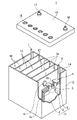
- FIG. 1 shows the appearance of an example of a lead storage battery according to an embodiment of the present invention.
- the lead-acid battery 1 includes an electric tank 12 for accommodating a plate group 11 and an electrolytic solution (not shown).
- the inside of the electric tank 12 is partitioned into a plurality of cell chambers 14 by a partition wall 13.
- One electrode plate group 11 is housed in each cell chamber 14.
- the opening of the battery case 12 is closed by a lid 15 including a positive electrode terminal 16 and a negative electrode terminal 17.
- the lid 15 is provided with a liquid spout 18 for each cell chamber. At the time of refilling water, the liquid spout 18 is removed and the refilling liquid is replenished.
- the liquid spout 18 may have a function of discharging the gas generated in the cell chamber 14 to the outside of the battery.
- the electrode plate group 11 is configured by alternately laminating a plurality of negative electrode plates 3 and a plurality of positive electrode plates 2 via a separator 4.
- the separator 4 has a bag shape, and the positive electrode plates 2 are packaged one by one.
- the positive electrode shelf portion 6 for connecting the ear portions 2a of the plurality of positive electrode plates 2 in parallel is connected to the through connection body 8, and the ear portions of the plurality of negative electrode plates 3 are connected.
- the negative electrode shelf portion 5 that connects 3a in parallel is connected to the negative electrode column 7.
- the negative electrode column 7 is connected to the negative electrode terminal 17 outside the lid 15.
- the positive electrode column 9 is connected to the positive electrode shelf 6 and the through-connecting body 8 is connected to the negative electrode shelf 5.
- the positive electrode column 9 is connected to the positive electrode terminal 16 outside the lid 15.
- Each through-connecting body 8 passes through a through-hole provided in the partition wall 13 and connects the electrode plates 11 of the adjacent cell chambers 14 in series.
- the positive electrode shelf portion 6 is formed by welding the selvage portions 2a provided on the upper part of each positive electrode plate 2 by a cast-on-strap method or a burning method.
- the negative electrode shelf portion 5 is also formed by welding the selvage portions 3a provided on the upper portions of the negative electrode plates 3 to each other, as in the case of the positive electrode shelf portion 6.
- the lid 15 of the lead storage battery has a single structure (single lid), but is not limited to the case shown in the illustrated example.
- the lid 15 may have, for example, a double structure including an inner lid and an outer lid (or upper lid).
- the lid having a double structure is provided with a reflux structure between the inner lid and the outer lid for returning the electrolytic solution to the inside of the battery (inside the inner lid) from the reflux port provided in the inner lid. May be good.
- the test battery used for the evaluation has a rated voltage of 2 V / cell and a rated 20-hour rate capacity of 60 Ah.
- the electrode plate group has seven positive electrode plates and eight negative electrode plates that are alternately laminated, and the positive electrode plates are housed in a bag-shaped separator.
- ⁇ PSOC cycle test ⁇ In a water tank at 25 ° C. ⁇ 3 ° C., the following steps 1 to 7 are repeated until the life is determined. The number of cycles until the life is determined is measured with the combination of step 2 and step 3 as one cycle. When the discharge end voltage becomes 1.67 V / cell or less in step 1 or step 3, the life is determined. The larger the number of cycles in the combination of step 2 and step 3, the better the cycle life in PSOC.
- Step 1 Discharge for 2.5 hours at a constant current of 12.0
- Step 2 Charge for 40 minutes under the conditions of constant voltage 2.4 V / cell and maximum current 21.0
- Step 3 30 minutes at a constant current of 21.0
- Discharging step 4 Repeating the combination of step 2 and step 3 85 times
- Step 5 Charging for 18 hours under the condition of constant voltage 2.67V / cell and maximum current 6.0A:
- Step 6 1 at constant current 3.0A
- Step 7 to discharge to .75V / cell Return to step 1 after step 7 to charge for 24 hours under the condition of constant voltage 2.67V / cell and maximum current 15.0A.
- Step A Discharge at a constant current of 25 A
- Step B Charge for 10 minutes under the conditions of a constant voltage of 2.47 V / cell and a maximum current of 25 A.
- the amount of overcharged electricity (Ah) per cycle is obtained by summing and averaging the amount of overcharged electricity (charged electricity amount-discharged electricity amount) in each cycle up to 1220 cycles.
- control valve type lead acid battery according to the present invention is collectively described below.
- the electrode plate group includes a positive electrode plate, a negative electrode plate, and a separator interposed between the positive electrode plate and the negative electrode plate.
- the pull-out load when pulling out the electrode plate group from the electric tank is 1.5 times or more the own weight of the electrode plate group.
- the surface roughness of the negative electrode plate is 0.4 mm or less, and the surface roughness is 0.4 mm or less.
- the negative electrode plate contains a negative electrode material and contains a negative electrode material.
- the negative electrode material contains a polymer compound and contains.
- the polymer compound is a lead-acid battery having a peak in the range of 3.2 ppm or more and 3.8 ppm or less in a chemical shift of 1 H-NMR spectrum measured using deuterated chloroform as a solvent.
- the electrode plate group includes a positive electrode plate, a negative electrode plate, and a separator interposed between the positive electrode plate and the negative electrode plate.
- the pull-out load when pulling out the electrode plate group from the electric tank is 1.5 times or more the own weight of the electrode plate group.
- the surface roughness of the negative electrode plate is 0.4 mm or less, and the surface roughness is 0.4 mm or less.
- the negative electrode plate contains a negative electrode material and contains a negative electrode material.
- the negative electrode material contains a polymer compound and contains.
- the polymer compound is a lead-acid battery having a repeating structure of an oxyC 2-4 alkylene unit.
- the hydroxy compound is selected from the group consisting of a poly C 2-4 alkylene glycol, a copolymer containing a repeating structure of an oxy C 2-4 alkylene unit, and a poly C 2-4 alkylene oxide adduct of a polyol.
- the polymer compound contains an oxygen atom bonded to the terminal group and -CH 2 -group and / or -CH ⁇ group bonded to the oxygen atom.
- the integral value of the peak, the integral value of the peak of the -CH2 -group hydrogen atom, and the integral value of the peak of the -CH ⁇ group hydrogen atom account for the sum of the peak.
- the lead storage battery according to any one of (1) to (7) above, wherein the ratio of the integrated value is 85% or more.
- the polymer compound has one or more hydrophobic groups and has one or more hydrophobic groups.
- the polymer compound is polyethylene glycol, polypropylene glycol, polyethylene glycol oleate, polyethylene glycol dioleate, polyethylene glycol dilaurate, polyethylene glycol distearate, polyoxyethylene coconut oil fatty acid sorbitan, polyoxyethylene sorbitan oleate, stearer. Any one of (1) to (9) above, which is at least one selected from the group consisting of polyoxyethylene sorbitan acid, polyoxyethylene lauryl ether, polyoxyethylene tetradecyl ether and polyoxyethylene cetyl ether. Lead storage battery described in.
- Lead-acid batteries R1 to R5 >> (1) Preparation of lead-acid battery (a) Preparation of negative electrode plate Lead powder as a raw material, a predetermined amount of sodium lignin sulfonate (organic shrink-proofing agent), barium sulfate, carbon black, and polyethylene oleate which is a polymer compound, respectively. Glycol (PEG oleate) and an appropriate amount of aqueous sulfuric acid are mixed to obtain a negative electrode paste.
- the content of the polymer compound in the negative electrode electrode material obtained by the above procedure is the value shown in Table 1, the content of sodium lignin sulfonate is 0.1% by mass, and the content of barium sulfate is 0.4% by mass.
- Each component is mixed so that the content of carbon black is 0.2% by mass.
- the concentration and amount of the sulfuric acid aqueous solution are adjusted so that the density of the negative electrode material contained in the fully charged lead-acid battery after chemical conversion is 3.6 g / cm 3 .
- the negative electrode paste is filled in the mesh portion of the expanded lattice made of Pb—Ca—Sn alloy and aged and dried to obtain an unchemicald negative electrode plate.
- the negative electrode paste When filling the mesh part of the expanded grid with the negative electrode paste, the negative electrode paste is pressed with a conventional general jig.
- the surface roughness of the negative electrode plate measured by the procedure described above is larger than 0.4 mm (0.5 mm).
- the test battery has a rated voltage of 2 V / cell and a rated 20-hour rate capacity of 60 Ah.
- the electrode plate group of the test battery has a positive electrode plate housed in a bag-shaped separator, and is composed of 7 positive electrode plates and 8 negative electrode plates.
- As the bag-shaped separator one formed of a polyethylene microporous membrane is used.
- a group of electrode plates is housed in a polypropylene electric tank together with an electrolytic solution (sulfuric acid aqueous solution) and chemically formed in the electric tank to produce a liquid-type lead-acid battery.
- the withdrawal load ratio obtained by the method described above: W2 / W1 is 1.0, and the specific gravity of the electrolytic solution in the fully charged lead-acid battery at 20 ° C. is 1.28.
- the pull-out load ratio: W2 / W1 is set together with the spacer when the electrode plate group is housed in the battery case so that the W2 / W1 value of the lead-acid battery measured after disassembly becomes the value shown in Tables 1 to 8. Adjust by inserting the electrode plate group or pressing the electrode plate group with a predetermined jig.
- Lead-acid batteries R6 to R10 When filling the mesh portion of the expanded lattice with the negative electrode paste, the negative electrode paste has irregularities so that the surface roughness of the negative electrode plate measured by the above procedure is 0.4 mm or less (0.1 mm).
- a lead-acid battery is produced and evaluated in the same manner as the lead-acid batteries R1 to R5, except that the lead-acid battery is pressed with a jig having no surface.
- a peak derived from -CH 2- of the oxyethylene unit is observed in the range of the chemical shift of 3.2 ppm or more and 3.42 ppm or less.
- the ratio to the total value of is 96 to 100%.
- Lead-acid batteries R11-R15 Lead-acid batteries are produced and evaluated in the same manner as the lead-acid batteries R1 to R5, except that the withdrawal load ratio: W2 / W1 obtained by the method described above is set to 1.5 by the same method as described above. The results are shown in Table 2.
- Lead-acid batteries E1 to E5 >> Similarly, lead-acid batteries are produced and evaluated in the same manner as the lead-acid batteries R6 to R10, except that the withdrawal load ratio: W2 / W1 obtained by the above-mentioned method is 1.5. The results are shown in Table 2.
- Lead-acid batteries R16-R20 are produced and evaluated in the same manner as the lead-acid batteries R1 to R5, except that the withdrawal load ratio: W2 / W1 obtained by the above-mentioned method is set to 1.8. The results are shown in Table 3.
- Lead-acid batteries E6 to E12 are produced and evaluated in the same manner as the lead-acid batteries R6 to R10, except that the withdrawal load ratio: W2 / W1 obtained by the above-mentioned method is set to 1.8 and the surface roughness is shown in Table 3. implement. The results are shown in Table 3.
- Lead-acid batteries R21-R25 >> Similarly, lead-acid batteries are produced and evaluated in the same manner as the lead-acid batteries R1 to R5, except that the withdrawal load ratio: W2 / W1 obtained by the method described above is 3.5. The results are shown in Table 4.
- Lead-acid batteries E13 to E17 are produced and evaluated in the same manner as the lead-acid batteries R6 to R10, except that the withdrawal load ratio: W2 / W1 obtained by the method described above is 3.5. The results are shown in Table 4.
- Lead-acid batteries R26-R30 are produced and evaluated in the same manner as the lead-acid batteries R1 to R5, except that the withdrawal load ratio: W2 / W1 obtained by the above-mentioned method is 6.0. The results are shown in Table 5.
- Lead-acid batteries E18-E24 are produced and evaluated in the same manner as the lead-acid batteries R6 to R10, except that the withdrawal load ratio: W2 / W1 obtained by the above-mentioned method is 6.0 and the surface roughness is shown in Table 5. implement. The results are shown in Table 5.
- Lead-acid batteries R31-R35 >> Similarly, lead-acid batteries are produced and evaluated in the same manner as the lead-acid batteries R1 to R5, except that the withdrawal load ratio: W2 / W1 obtained by the above-mentioned method is 9.0. The results are shown in Table 6.
- Lead-acid batteries E25-E31 are produced and evaluated in the same manner as the lead-acid batteries R6 to R10, except that the withdrawal load ratio: W2 / W1 obtained by the above-mentioned method is 9.0 and the surface roughness is shown in Table 6. implement. The results are shown in Table 6.
- the pull-out load is 1.5 times or more the own weight of the electrode plate group, and the surface roughness of the negative electrode plate is 0.4 mm or less. Therefore, it is possible to improve the cycle life, but on the other hand, it can be seen that the amount of overcharged electricity increases.
- Lead-acid battery E32-36 A lead-acid battery is prepared and evaluated in the same manner as E8, except that the polymer compound is changed from PEG to the following. The results are shown in Table 7.
- Lead-acid battery E37-E41 Lead-acid batteries are produced and evaluated in the same manner as the lead-acid batteries E32 to E36, except that the withdrawal load ratio: W2 / W1 obtained by the method described above is 6.0. The results are shown in Table 8.
- the lead-acid battery according to the present invention is suitable for use in an idling stop vehicle as, for example, a lead-acid battery for IS that is charged and discharged under PSOC conditions.
- the lead-acid battery can be suitably used, for example, as a power source for starting a vehicle (automobile, motorcycle, etc.) or an industrial power storage device (for example, a power source for an electric vehicle (forklift, etc.)). It should be noted that these uses are merely examples and are not limited to these uses.
Landscapes
- Chemical & Material Sciences (AREA)
- Chemical Kinetics & Catalysis (AREA)
- Electrochemistry (AREA)
- General Chemical & Material Sciences (AREA)
- Engineering & Computer Science (AREA)
- Manufacturing & Machinery (AREA)
- Secondary Cells (AREA)
Priority Applications (1)
| Application Number | Priority Date | Filing Date | Title |
|---|---|---|---|
| JP2022565151A JP7798037B2 (ja) | 2020-11-27 | 2021-10-28 | 鉛蓄電池 |
Applications Claiming Priority (2)
| Application Number | Priority Date | Filing Date | Title |
|---|---|---|---|
| JP2020-197588 | 2020-11-27 | ||
| JP2020197588 | 2020-11-27 |
Publications (1)
| Publication Number | Publication Date |
|---|---|
| WO2022113634A1 true WO2022113634A1 (ja) | 2022-06-02 |
Family
ID=81755739
Family Applications (1)
| Application Number | Title | Priority Date | Filing Date |
|---|---|---|---|
| PCT/JP2021/039831 Ceased WO2022113634A1 (ja) | 2020-11-27 | 2021-10-28 | 鉛蓄電池 |
Country Status (2)
| Country | Link |
|---|---|
| JP (1) | JP7798037B2 (https=) |
| WO (1) | WO2022113634A1 (https=) |
Citations (8)
| Publication number | Priority date | Publication date | Assignee | Title |
|---|---|---|---|---|
| JPS60182662A (ja) * | 1984-02-28 | 1985-09-18 | Japan Storage Battery Co Ltd | 鉛蓄電池 |
| JPH09147869A (ja) * | 1995-11-17 | 1997-06-06 | Shin Kobe Electric Mach Co Ltd | 鉛蓄電池 |
| JPH10162834A (ja) * | 1996-11-28 | 1998-06-19 | Japan Storage Battery Co Ltd | 鉛蓄電池 |
| JP2000030734A (ja) * | 1998-07-09 | 2000-01-28 | Shin Kobe Electric Mach Co Ltd | 密閉形鉛蓄電池 |
| JP2003346792A (ja) * | 2002-05-30 | 2003-12-05 | Matsushita Electric Ind Co Ltd | 鉛蓄電池用極板の製造方法 |
| JP2019071165A (ja) * | 2016-03-01 | 2019-05-09 | 日立化成株式会社 | 鉛蓄電池用樹脂、電極、鉛蓄電池及び自動車 |
| WO2020080420A1 (ja) * | 2018-10-16 | 2020-04-23 | 株式会社Gsユアサ | 鉛蓄電池 |
| WO2020241884A1 (ja) * | 2019-05-31 | 2020-12-03 | 株式会社Gsユアサ | 鉛蓄電池 |
Family Cites Families (1)
| Publication number | Priority date | Publication date | Assignee | Title |
|---|---|---|---|---|
| EP4234630A3 (en) * | 2017-10-04 | 2023-10-04 | Mitsubishi Chemical Corporation | Rubber-containing graft polymer, resin composition containing rubber-containing graft polymer, and shaped article thereof |
-
2021
- 2021-10-28 WO PCT/JP2021/039831 patent/WO2022113634A1/ja not_active Ceased
- 2021-10-28 JP JP2022565151A patent/JP7798037B2/ja active Active
Patent Citations (8)
| Publication number | Priority date | Publication date | Assignee | Title |
|---|---|---|---|---|
| JPS60182662A (ja) * | 1984-02-28 | 1985-09-18 | Japan Storage Battery Co Ltd | 鉛蓄電池 |
| JPH09147869A (ja) * | 1995-11-17 | 1997-06-06 | Shin Kobe Electric Mach Co Ltd | 鉛蓄電池 |
| JPH10162834A (ja) * | 1996-11-28 | 1998-06-19 | Japan Storage Battery Co Ltd | 鉛蓄電池 |
| JP2000030734A (ja) * | 1998-07-09 | 2000-01-28 | Shin Kobe Electric Mach Co Ltd | 密閉形鉛蓄電池 |
| JP2003346792A (ja) * | 2002-05-30 | 2003-12-05 | Matsushita Electric Ind Co Ltd | 鉛蓄電池用極板の製造方法 |
| JP2019071165A (ja) * | 2016-03-01 | 2019-05-09 | 日立化成株式会社 | 鉛蓄電池用樹脂、電極、鉛蓄電池及び自動車 |
| WO2020080420A1 (ja) * | 2018-10-16 | 2020-04-23 | 株式会社Gsユアサ | 鉛蓄電池 |
| WO2020241884A1 (ja) * | 2019-05-31 | 2020-12-03 | 株式会社Gsユアサ | 鉛蓄電池 |
Also Published As
| Publication number | Publication date |
|---|---|
| JPWO2022113634A1 (https=) | 2022-06-02 |
| JP7798037B2 (ja) | 2026-01-14 |
Similar Documents
| Publication | Publication Date | Title |
|---|---|---|
| JP7173322B2 (ja) | 鉛蓄電池 | |
| WO2022113633A1 (ja) | 鉛蓄電池 | |
| JP7677347B2 (ja) | 鉛蓄電池 | |
| WO2020241547A1 (ja) | 鉛蓄電池 | |
| JP7661978B2 (ja) | 鉛蓄電池 | |
| WO2022113634A1 (ja) | 鉛蓄電池 | |
| JP7718427B2 (ja) | 鉛蓄電池 | |
| JP7786391B2 (ja) | 鉛蓄電池 | |
| JP7643017B2 (ja) | 制御弁式鉛蓄電池 | |
| WO2020241883A1 (ja) | 鉛蓄電池 | |
| JP7694582B2 (ja) | 鉛蓄電池 | |
| EP4254549B1 (en) | Lead-acid battery | |
| JP7679841B2 (ja) | 鉛蓄電池 | |
| JP7687348B2 (ja) | 鉛蓄電池 | |
| JP7819461B2 (ja) | 鉛蓄電池 | |
| JP7643016B2 (ja) | 鉛蓄電池 | |
| WO2020241880A1 (ja) | 鉛蓄電池 | |
| WO2022113627A1 (ja) | 鉛蓄電池 | |
| JP7661690B2 (ja) | 鉛蓄電池 | |
| JP7754108B2 (ja) | 鉛蓄電池 | |
| WO2020241879A1 (ja) | 鉛蓄電池 |
Legal Events
| Date | Code | Title | Description |
|---|---|---|---|
| 121 | Ep: the epo has been informed by wipo that ep was designated in this application |
Ref document number: 21897610 Country of ref document: EP Kind code of ref document: A1 |
|
| ENP | Entry into the national phase |
Ref document number: 2022565151 Country of ref document: JP Kind code of ref document: A |
|
| NENP | Non-entry into the national phase |
Ref country code: DE |
|
| 122 | Ep: pct application non-entry in european phase |
Ref document number: 21897610 Country of ref document: EP Kind code of ref document: A1 |