WO2022113164A1 - Optical fiber sensing system, optical fiber sensing method, and optical fiber sensing device - Google Patents
Optical fiber sensing system, optical fiber sensing method, and optical fiber sensing device Download PDFInfo
- Publication number
- WO2022113164A1 WO2022113164A1 PCT/JP2020/043629 JP2020043629W WO2022113164A1 WO 2022113164 A1 WO2022113164 A1 WO 2022113164A1 JP 2020043629 W JP2020043629 W JP 2020043629W WO 2022113164 A1 WO2022113164 A1 WO 2022113164A1
- Authority
- WO
- WIPO (PCT)
- Prior art keywords
- optical fiber
- state information
- status information
- specified
- sensing data
- Prior art date
Links
- 239000013307 optical fiber Substances 0.000 title claims abstract description 138
- 238000000034 method Methods 0.000 title claims description 32
- 238000004458 analytical method Methods 0.000 claims abstract description 90
- 230000003287 optical effect Effects 0.000 claims abstract description 51
- 238000004891 communication Methods 0.000 claims abstract description 41
- 238000012544 monitoring process Methods 0.000 claims description 49
- 230000007717 exclusion Effects 0.000 claims description 41
- 239000000284 extract Substances 0.000 claims description 8
- 239000000835 fiber Substances 0.000 claims description 5
- 230000006866 deterioration Effects 0.000 description 10
- 238000005259 measurement Methods 0.000 description 4
- 238000012545 processing Methods 0.000 description 3
- 241001465754 Metazoa Species 0.000 description 2
- 230000006399 behavior Effects 0.000 description 2
- 238000010586 diagram Methods 0.000 description 2
- 230000000694 effects Effects 0.000 description 2
- 230000006870 function Effects 0.000 description 2
- 230000001052 transient effect Effects 0.000 description 2
- 230000005540 biological transmission Effects 0.000 description 1
- 238000005352 clarification Methods 0.000 description 1
- 238000010276 construction Methods 0.000 description 1
- 230000003628 erosive effect Effects 0.000 description 1
- 238000004880 explosion Methods 0.000 description 1
- 230000008014 freezing Effects 0.000 description 1
- 238000007710 freezing Methods 0.000 description 1
- 239000004973 liquid crystal related substance Substances 0.000 description 1
- 238000001556 precipitation Methods 0.000 description 1
- 206010037844 rash Diseases 0.000 description 1
- 230000000717 retained effect Effects 0.000 description 1
- 150000003839 salts Chemical class 0.000 description 1
- 239000013049 sediment Substances 0.000 description 1
- 239000004065 semiconductor Substances 0.000 description 1
- 239000007787 solid Substances 0.000 description 1
Images


Classifications
-
- G—PHYSICS
- G01—MEASURING; TESTING
- G01H—MEASUREMENT OF MECHANICAL VIBRATIONS OR ULTRASONIC, SONIC OR INFRASONIC WAVES
- G01H9/00—Measuring mechanical vibrations or ultrasonic, sonic or infrasonic waves by using radiation-sensitive means, e.g. optical means
- G01H9/004—Measuring mechanical vibrations or ultrasonic, sonic or infrasonic waves by using radiation-sensitive means, e.g. optical means using fibre optic sensors
-
- G—PHYSICS
- G01—MEASURING; TESTING
- G01H—MEASUREMENT OF MECHANICAL VIBRATIONS OR ULTRASONIC, SONIC OR INFRASONIC WAVES
- G01H9/00—Measuring mechanical vibrations or ultrasonic, sonic or infrasonic waves by using radiation-sensitive means, e.g. optical means
-
- G—PHYSICS
- G06—COMPUTING; CALCULATING OR COUNTING
- G06Q—INFORMATION AND COMMUNICATION TECHNOLOGY [ICT] SPECIALLY ADAPTED FOR ADMINISTRATIVE, COMMERCIAL, FINANCIAL, MANAGERIAL OR SUPERVISORY PURPOSES; SYSTEMS OR METHODS SPECIALLY ADAPTED FOR ADMINISTRATIVE, COMMERCIAL, FINANCIAL, MANAGERIAL OR SUPERVISORY PURPOSES, NOT OTHERWISE PROVIDED FOR
- G06Q50/00—Systems or methods specially adapted for specific business sectors, e.g. utilities or tourism
- G06Q50/10—Services
Definitions
- the present disclosure relates to an optical fiber sensing system, an optical fiber sensing method, and an optical fiber sensing device.
- the state information is, for example, the behavior of a person, a vehicle, or an animal, the state of a structure such as a utility pole, the state of a railroad track, a road, the state of weather, or the like. Further, the optical fiber is laid, for example, on a structure such as a utility pole, a road, a railroad track, a seabed, or the like.
- state information is preferably provided only to a specific service provider.
- the privacy status information of a company should be provided only to the service provider of the company, and should be avoided from being leaked to other service providers. Therefore, there is a need to provide status information according to the service provider to the service provider.
- Examples of the related technique include the technique described in Patent Document 1.
- the privacy protection mode and the normal mode are switched according to the position of the subject. For example, when the subject moves to a privacy space such as a toilet, the subject switches to the privacy protection mode, and the measurement is interrupted or the measurement data is not recorded during that time.
- an object of the present disclosure is to provide an optical fiber sensing system, an optical fiber sensing method, and an optical fiber sensing device that can solve the above-mentioned problems and provide state information according to a service provider to the service provider. It is in.
- the optical fiber sensing system is Fiber optic networks that detect sensing data and A communication unit that receives an optical signal from the optical fiber network, From a plurality of status information, a specific part that identifies the status information according to the service provider, and An analysis unit that analyzes the specified state information based on the sensing data superimposed on the optical signal by using the analysis method related to the specified state information among the plurality of analysis methods.
- a provider that provides the specified status information to the service provider, and To prepare for.
- the optical fiber sensing method is It is an optical fiber sensing method using an optical fiber sensing device.
- a reception step that receives an optical signal from an optical fiber network that detects sensing data,
- An analysis step for analyzing the specified state information based on the sensing data superimposed on the optical signal by using the analysis method related to the specified state information among the plurality of analysis methods.
- the optical fiber sensing device is A communication unit that receives optical signals from an optical fiber network that detects sensing data, From a plurality of status information, a specific part that identifies the status information according to the service provider, and An analysis unit that analyzes the specified state information based on the sensing data superimposed on the optical signal by using the analysis method related to the specified state information among the plurality of analysis methods.
- a provider that provides the specified status information to the service provider, and To prepare for.
- an optical fiber sensing system an optical fiber sensing method, and an optical fiber sensing device that can provide state information according to the service provider to the service provider.
- FIG. 1 It is a figure which shows the structural example of the optical fiber sensing system which concerns on Embodiment 1.
- FIG. It is a figure which shows the example of the area DB held by the analysis part which concerns on Embodiment 1.
- FIG. It is a flow diagram which shows the example of the operation flow of the optical fiber sensing system which concerns on Embodiment 1.
- FIG. It is a figure which shows the structural example of the optical fiber sensing system which concerns on Embodiment 2.
- FIG. It is a figure which shows the example of the vibration pattern extracted by the analysis part which concerns on Embodiment 2.
- FIG. 1 It is a figure which shows the example of the electric pole DB held by the analysis part which concerns on Embodiment 2.
- FIG. It is a figure which shows the example of the monitoring exclusion target DB held by the specific part which concerns on Embodiment 2.
- FIG. It is a figure which shows the structural example of the optical fiber sensing system which concerns on other embodiment.
- the optical fiber sensing system includes an optical fiber network 10 and an optical fiber sensing device 20. Further, the optical fiber sensing device 20 includes a communication unit 21, a specific unit 22, an analysis unit 23, and a provision unit 24.
- the optical fiber network 10 is composed of one or more optical fibers 11.
- the optical fiber 11 may be an optical fiber dedicated to sensing, or may be an optical fiber for both communication and sensing. Further, the optical fiber 11 may be an existing optical fiber or a newly installed optical fiber.
- the places where the optical fiber 11 can be laid are as follows, for example. ⁇ Structures / railroads, roads / underground, seabed such as utility poles, bridges, tunnels, pipes, dams, etc.
- the state information that can be analyzed by the optical fiber sensing system according to the first embodiment is, for example, a plurality of state information as follows. ⁇ Conditions including deterioration of structures such as electric poles, bridges, tunnels, pipes, dams ⁇ Conditions including deterioration of railroads and roads ⁇ Conditions of railroads and roads ⁇ Behavior of people, vehicles, animals, etc.
- the communication unit 21 receives an optical signal from the optical fiber network 10. For example, the communication unit 21 sends pulsed light to the optical fiber 11 constituting the optical fiber network 10, and receives the backward scattered light generated by the pulsed light being transmitted through the optical fiber 11 as an optical signal. ..
- the optical fiber 11 can detect sensing data including vibration data, sound data, temperature data, and the like, and this sensing data is superimposed on the optical signal transmitted through the optical fiber 11.
- the analysis unit 23 can use a plurality of analysis methods related to the above-mentioned plurality of state information.
- the analysis unit 23 uses an analysis method related to the state information to obtain the state information based on the sensing data superimposed on the optical signal received by the communication unit 21. To analyze.
- the sensing data superimposed on the optical signal is vibration data, sound data, temperature data, etc., as described above, but vibration data alone is a unique pattern of vibration related to various state information.
- vibration data when the optical fiber 11 is laid on a utility pole, the sensing data (vibration data) has a unique pattern of vibration according to the deterioration state of the utility pole and a unique pattern of vibration according to the traffic condition of a vehicle traveling near the utility pole. It includes patterns, unique patterns of vibration according to weather conditions, etc.
- the eigenpattern related to a certain state information is a eigenpattern that dynamically changes according to the state indicated by the state information.
- the analysis unit 23 analyzes the state information by using an analysis method related to the state information as described above.
- this analysis method for example, a unique pattern related to the state information is extracted from the sensing data superimposed on the optical signal received by the communication unit 21, and the extracted unique pattern is analyzed to obtain the state information. It is a method of analyzing.
- some status information is preferably provided only to a specific service provider.
- the privacy status information of a company should be provided only to the service provider of the company, and should be avoided from being leaked to other service providers.
- the specifying unit 22 specifies the state information according to the service provider from the plurality of state information. At this time, the specifying unit 22 identifies the status information of the monitoring exclusion target from the plurality of status information, and obtains the status information obtained by excluding the monitoring exclusion target status information from the plurality of status information according to the service provider. It may be specified as state information.
- the state information to be excluded from monitoring is, for example, state information related to confidentiality of the national and local governments, state information related to privacy of individuals and companies, and the like.
- the status information of the monitoring exclusion target may be defined for each service providing destination according to the policy of the service providing destination, or the status information of the monitoring exclusion target common to the service providing destinations may be defined. ..
- the analysis unit 23 uses an analysis method related to the state information specified by the specific unit 22, and uses a unique pattern related to the specified state information from the sensing data superimposed on the optical signal received by the communication unit 21. And analyze the identified state information by analyzing the extracted unique pattern.
- the sensing data includes all data such as vibration generated around the optical fiber 11. Therefore, some sensing data are not appropriate for analysis of state information.
- the analysis unit 23 excludes the sensing data to be monitored and excluded from the sensing data superimposed on the optical signal received by the communication unit 21, and uses the remaining sensing data to specify the state specified by the specific unit 22. You may analyze the information.
- Sensing data subject to monitoring exclusion includes sensing data detected at national and local government facilities, and sensing data related to personal information of individuals and companies.
- the sensing data to be excluded from monitoring may be the sensing data detected in a specific position or region, the sensing data detected in a specific time zone, or the sensing data of a specific frequency. ..
- the analysis unit 23 is based on the time difference between the time when the pulsed light is sent to the optical fiber 11 by the communication unit 21 and the time when the optical signal is received from the optical fiber 11 by the communication unit 21.
- the position (distance from the communication unit 21) on the optical fiber 11 in which the sensing data superimposed on the signal is detected can be specified.
- the analysis unit 23 creates an area DB (DataBase) in which the position on the optical fiber 11 (distance from the communication unit 21) and the identifier of each area on the map are associated with each other. It may be held in advance.
- the analysis unit 23 can determine in which region on the map the sensing data is detected, that is, in which region the state information is being analyzed.
- the providing unit 24 provides the service provider with the state information specified by the specifying unit 22 and analyzed by the analysis unit 23.
- the optical fiber network 10 detects sensing data (step S11).
- the communication unit 21 receives an optical signal on which sensing data is superimposed from the optical fiber network 10 (optical fiber 11) (step S12).
- the specifying unit 22 specifies the state information according to the service provider from the plurality of state information that can be analyzed by the optical fiber sensing system according to the first embodiment (step S13).
- this specification may be performed by a method of specifying the state information of the monitoring exclusion target.
- the analysis unit 23 uses the analysis method related to the state information specified by the specific unit 22 among the plurality of analysis methods, and is based on the sensing data superimposed on the optical signal received by the communication unit 21. Then, the specified state information is analyzed (step S14). As described above, this analysis may be performed by a method of extracting a unique pattern related to the specified state information from the sensing data and analyzing the extracted unique pattern. After that, the providing unit 24 provides the service providing destination with the state information specified by the specifying unit 22 and analyzed by the analysis unit 23 (step S15).
- the specifying unit 22 specifies the state information according to the service providing destination from the plurality of state information.
- the analysis unit 23 analyzes the specified state information based on the sensing data superimposed on the received optical signal by using the analysis method related to the specified state information among the plurality of analysis methods. Thereby, the state information according to the service providing destination can be provided to the service providing destination.
- the specifying unit 22 identifies the status information of the monitoring exclusion target from the plurality of status information, and responds to the service provider based on the status information of the monitoring exclusion target. You may specify the state information. As a result, it is possible to prevent the state information of the monitoring exclusion target, such as the state information related to the privacy of the company, from being leaked to the service provider of another company.
- the analysis unit 23 may exclude the sensing data to be monitored and excluded from the sensing data and analyze the specified state information based on the remaining sensing data. As a result, it is possible to prevent the sensing data to be excluded from monitoring, such as the sensing data detected at the national facility, from being used for the analysis of the state information.
- the optical fiber sensing system according to the second embodiment is an example in which the optical fiber sensing system according to the first embodiment described above is more embodied.
- the optical fiber network 10 is configured by the optical fiber 11 laid on the utility pole P, and the three service providers X, Y, and Z are configured. Existing.
- -Status information A Deterioration status of utility pole
- P-Status information B Traffic status of vehicles traveling near utility pole
- C Weather status
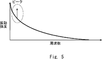
- the analysis unit 23 extracts a vibration pattern as shown in FIGS. 5 and 6 from the sensing data superimposed on the optical signal received by the communication unit 21.
- 5 and 6 are vibration patterns after FFT (Fast Fourier Transform) of a vibration pattern in which the horizontal axis indicates time and the vertical axis indicates vibration intensity.
- FFT Fast Fourier Transform
- a peak of vibration intensity occurs in the vibration patterns shown in FIGS. 5 and 6, a peak of vibration intensity occurs.
- the magnitude of the peak of the vibration intensity and the frequency at which this peak occurs differ depending on the deterioration state of the utility pole P. Specifically, in the state where the utility pole P is deteriorated (FIG. 6), the magnitude of the peak of the vibration intensity is larger than that in the state where the utility pole P is normal (FIG. 5), and this peak is larger.
- the generated frequency is shifted to the high frequency side.
- the analysis unit 23 determines the deterioration state of the utility pole P based on the magnitude of the peak of the vibration intensity and the frequency at which this peak occurs. As shown in FIG. 7, the analysis unit 23 holds in advance a utility pole DB in which a position on the optical fiber 11 (distance from the communication unit 21) and an identifier of each utility pole P are associated with each other. Is also good. As a result, the analysis unit 23 can determine which utility pole P has detected the sensing data, that is, which utility pole P is analyzing the deterioration state.
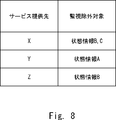
- the state information of the monitoring exclusion target is defined for each of the service providing destinations X, Y, and Z, and the specific unit 22 is as shown in FIG. It is assumed that the monitoring exclusion target DB in which the identifiers of the service providing destinations X, Y, and Z and the status information of the monitoring exclusion target of each service providing destination X, Y, Z are associated with each other is stored in advance.
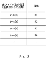
- the sensing data to be excluded from monitoring is defined as the sensing data detected in the region R1 (see FIG. 2), and the analysis unit 23 monitors the sensing data. It is assumed that the information (not shown) of the sensing data to be excluded is retained in advance.
- the operation flow of the optical fiber sensing system according to the second embodiment is the same as that of FIG. 3 of the first embodiment described above. Specifically, it is as follows.
- Step S11 First, the optical fiber network 10 (optical fiber 11) detects sensing data.
- Step S12 Subsequently, the communication unit 21 receives an optical signal on which sensing data is superimposed from the optical fiber network 10 (optical fiber 11).
- Step S13 Subsequently, the specifying unit 22 refers to the monitoring exclusion target DB of FIG. 8 and specifies the state information according to each of the service providing destinations X, Y, and Z in no particular order.
- the monitoring exclusion target of the service providing destination X is the status information B and C. Therefore, the specific unit 22 has state information A, B. That can be analyzed by the optical fiber sensing system according to the second embodiment.
- the state information A excluding the state information B and C from C is specified as the state information according to the service providing destination X.
- the specifying unit 22 specifies the state information B and C according to the service providing destination Y, and specifies the state information A and C according to the service providing destination Z.
- Step S14 Subsequently, the analysis unit 23 analyzes the state information A, B, and C in no particular order.
- the state information A indicating the deterioration state of the utility pole P is analyzed as follows.
- the analysis unit 23 acquires the sensing data superimposed on the optical signal received by the communication unit 21.
- the sensing data detected in the region R1 is defined as the sensing data to be excluded from monitoring.
- the analysis unit 23 removes the sensing data detected in the region R1 from the sensing data acquired above.
- the sensing data after this removal will be referred to as the remaining sensing data.
- the analysis unit 23 analyzes the state information A by using the analysis method related to the state information A. Specifically, the analysis unit 23 extracts a vibration pattern as shown in FIGS. 5 and 6 from the remaining sensing data, and the magnitude of the peak of the vibration intensity and the occurrence of this peak in the extracted vibration pattern. The deterioration state of the utility pole P is analyzed based on the frequency. At this time, the analysis unit 23 can determine which utility pole P is being analyzed by referring to the utility pole DB shown in FIG. 7. This completes the analysis of the state information A. The analysis unit 23 also analyzes the other state information B and C by using the analysis method related to the state information B and C.
- Step S15 After that, the providing unit 24 provides the state information A to the service providing destination X, provides the state information B and C to the service providing destination Y, and provides the service providing destination Z in no particular order. State information A and C are provided.
- the optical fiber sensing system according to the second embodiment is an example in which the optical fiber sensing system according to the first embodiment described above is more embodied. Therefore, according to the second embodiment, the same effect as that of the first embodiment described above can be obtained.
- the specific effects obtained in the second embodiment are as follows.
- -Status information corresponding to the service providing destinations X, Y, and Z can be provided to those service providing destinations X, Y, and Z, respectively.
- -It is possible to prevent the status information B and C of the monitoring exclusion target for the service providing destination X from leaking to the service providing destination X.
- the state information A is possible to prevent the state information A from leaking to the service providing destination Y, and it is possible to prevent the state information B from leaking to the service providing destination Z.
- -It is possible to prevent the sensing data to be excluded from monitoring, which is the sensing data detected in the region R1 (see FIG. 2), from being used for analysis.
- the communication unit 21 is provided inside the optical fiber sensing device 20, but the present invention is not limited to this.
- the communication unit 21 may be separated from the optical fiber sensing device 20.
- FIG. 9 shows a configuration example of an optical fiber sensing system in which the communication unit 21 is separated from the optical fiber sensing device 20.
- the optical fiber sensing device 20 can be installed at a location away from the communication unit 21, for example, on the cloud.
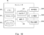
- the computer 30 includes a processor 301, a memory 302, a storage 303, an input / output interface (input / output I / F) 304, a communication interface (communication I / F) 305, and the like.
- the processor 301, the memory 302, the storage 303, the input / output interface 304, and the communication interface 305 are connected by a data transmission line for transmitting and receiving data to and from each other.
- the processor 301 is, for example, an arithmetic processing unit such as a CPU (Central Processing Unit) or a GPU (Graphics Processing Unit).
- the memory 302 is, for example, a memory such as a RAM (RandomAccessMemory) or a ROM (ReadOnlyMemory).
- the storage 303 is, for example, a storage device such as an HDD (Hard Disk Drive), an SSD (Solid State Drive), or a memory card. Further, the storage 303 may be a memory such as a RAM or a ROM.
- the storage 303 stores a program that realizes the functions of the components included in the optical fiber sensing device 20. By executing each of these programs, the processor 301 realizes the functions of the components included in the optical fiber sensing device 20.
- the processor 301 may read these programs onto the memory 302 and then execute the programs, or may execute the programs without reading them onto the memory 302. Further, the memory 302 and the storage 303 also play a role of storing information and data held by the components included in the optical fiber sensing device 20.
- Non-temporary computer-readable media include various types of tangible storage mediums.
- Examples of non-temporary computer-readable media include magnetic recording media (eg, flexible discs, magnetic tapes, hard disk drives), optomagnetic recording media (eg, optomagnetic discs), CD-ROMs (Compact Disc-ROMs), CDs. -R (CD-Recordable), CD-R / W (CD-ReWritable), semiconductor memory (for example, mask ROM, PROM (Programmable ROM), EPROM (Erasable PROM), flash ROM, RAM.
- transient computer readable medium May be supplied to the computer by various types of transient computer readable medium.
- transient computer readable media include electrical signals, optical signals, and electromagnetic waves.
- the computer-readable medium can supply the program to the computer via a wired communication path such as an electric wire and an optical fiber, or a wireless communication path.
- the input / output interface 304 is connected to a display device 3041, an input device 3042, a sound output device 3043, and the like.
- the display device 3041 is a device that displays a screen corresponding to drawing data processed by the processor 301, such as an LCD (Liquid Crystal Display), a CRT (Cathode Ray Tube) display, and a monitor.
- the input device 3042 is a device that receives an operator's operation input, and is, for example, a keyboard, a mouse, a touch sensor, and the like.
- the display device 3041 and the input device 3042 may be integrated and realized as a touch panel.
- the sound output device 3043 is a device such as a speaker that acoustically outputs sound corresponding to acoustic data processed by the processor 301.
- the communication interface 305 sends and receives data to and from an external device.
- the communication interface 305 communicates with an external device via a wired communication path or a wireless communication path.
- (Appendix 1) Fiber optic networks that detect sensing data and A communication unit that receives an optical signal from the optical fiber network, From a plurality of status information, a specific part that identifies the status information according to the service provider, and An analysis unit that analyzes the specified state information based on the sensing data superimposed on the optical signal by using the analysis method related to the specified state information among the plurality of analysis methods.
- the specific unit identifies the status information of the monitoring exclusion target from the plurality of status information, and specifies the status information according to the service provider based on the identified status information of the monitoring exclusion target.
- the optical fiber sensing system according to Appendix 1. (Appendix 3) The specific unit identifies the status information of the monitoring exclusion target according to the service providing destination from the plurality of status information, and responds to the service providing destination based on the identified status information of the monitoring exclusion target. Identify the status information
- the optical fiber sensing system according to Appendix 1. (Appendix 4) The analysis unit excludes the sensing data to be monitored and excluded from the sensing data superimposed on the optical signal, and analyzes the specified state information based on the remaining sensing data.
- the optical fiber sensing system according to any one of Supplementary note 1 to 3.
- the analysis method related to the specified state information extracts a pattern related to the specified state information from the sensing data superimposed on the optical signal, and is specified based on the extracted pattern.
- a method for analyzing state information The optical fiber sensing system according to any one of Supplementary note 1 to 4. (Appendix 6) It is an optical fiber sensing method using an optical fiber sensing device.
- a reception step that receives an optical signal from an optical fiber network that detects sensing data, A specific step to specify the status information according to the service provider from multiple status information, An analysis step for analyzing the specified state information based on the sensing data superimposed on the optical signal by using the analysis method related to the specified state information among the plurality of analysis methods.
- the state information of the monitoring exclusion target is specified from the plurality of state information, and the state information corresponding to the service provider is specified based on the specified state information of the monitoring exclusion target.
- the optical fiber sensing method according to Appendix 6.
- the state information of the monitoring exclusion target according to the service providing destination is specified from the plurality of state information, and based on the specified monitoring exclusion target state information, the service is provided according to the service providing destination. Identify the status information
- the sensing data to be excluded from monitoring is excluded from the sensing data superimposed on the optical signal, and the specified state information is analyzed based on the remaining sensing data.
- the optical fiber sensing method according to any one of Supplementary note 6 to 8.
- the analysis method related to the specified state information extracts a pattern related to the specified state information from the sensing data superimposed on the optical signal, and is specified based on the extracted pattern.
- a method for analyzing state information The optical fiber sensing method according to any one of Supplementary note 6 to 9.
- (Appendix 11) A communication unit that receives optical signals from an optical fiber network that detects sensing data, From a plurality of status information, a specific part that identifies the status information according to the service provider, and An analysis unit that analyzes the specified state information based on the sensing data superimposed on the optical signal by using the analysis method related to the specified state information among the plurality of analysis methods.
- the specific unit identifies the status information of the monitoring exclusion target from the plurality of status information, and specifies the status information according to the service provider based on the identified status information of the monitoring exclusion target.
- the optical fiber sensing device according to Appendix 11. The specific unit identifies the status information of the monitoring exclusion target according to the service providing destination from the plurality of status information, and responds to the service providing destination based on the identified status information of the monitoring exclusion target. Identify the status information
- the optical fiber sensing device according to Appendix 11. The analysis unit excludes the sensing data to be monitored and excluded from the sensing data superimposed on the optical signal, and analyzes the specified state information based on the remaining sensing data.
- the optical fiber sensing device according to any one of Supplementary note 11 to 13.
- the analysis method related to the specified state information extracts a pattern related to the specified state information from the sensing data superimposed on the optical signal, and is specified based on the extracted pattern.
- a method for analyzing state information The optical fiber sensing device according to any one of Supplementary note 11 to 14.
Abstract
Description
また、光ファイバは、例えば、電柱等の構造物、道路、線路、海底等に敷設される。 The state information is, for example, the behavior of a person, a vehicle, or an animal, the state of a structure such as a utility pole, the state of a railroad track, a road, the state of weather, or the like.
Further, the optical fiber is laid, for example, on a structure such as a utility pole, a road, a railroad track, a seabed, or the like.
そのため、サービス提供先に応じた状態情報を、そのサービス提供先に提供したいというニーズが存在する。 However, some state information is preferably provided only to a specific service provider. For example, the privacy status information of a company should be provided only to the service provider of the company, and should be avoided from being leaked to other service providers.
Therefore, there is a need to provide status information according to the service provider to the service provider.
しかし、特許文献1に記載の技術では、プライバシー保護モードの間の計測を中断又は計測データを記録しないため、所望の状態情報をそもそも得ることができず、上述したニーズに対応することはできない。 As described above, there is a need to provide status information according to a service provider to the service provider.
However, in the technique described in Patent Document 1, since the measurement during the privacy protection mode is interrupted or the measurement data is not recorded, the desired state information cannot be obtained in the first place, and the above-mentioned needs cannot be met.
センシングデータを検出する光ファイバネットワークと、
前記光ファイバネットワークから光信号を受信する通信部と、
複数の状態情報の中から、サービス提供先に応じた状態情報を特定する特定部と、
複数の解析手法のうち、前記特定された状態情報に関連する解析手法を用いて、前記光信号に重畳されたセンシングデータに基づいて、前記特定された状態情報を解析する解析部と、
前記サービス提供先に対し、前記特定された状態情報を提供する提供部と、
を備える。 The optical fiber sensing system according to one aspect is
Fiber optic networks that detect sensing data and
A communication unit that receives an optical signal from the optical fiber network,
From a plurality of status information, a specific part that identifies the status information according to the service provider, and
An analysis unit that analyzes the specified state information based on the sensing data superimposed on the optical signal by using the analysis method related to the specified state information among the plurality of analysis methods.
A provider that provides the specified status information to the service provider, and
To prepare for.
光ファイバセンシング装置による光ファイバセンシング方法であって、
センシングデータを検出する光ファイバネットワークから光信号を受信する受信ステップと、
複数の状態情報の中から、サービス提供先に応じた状態情報を特定する特定ステップと、
複数の解析手法のうち、前記特定された状態情報に関連する解析手法を用いて、前記光信号に重畳されたセンシングデータに基づいて、前記特定された状態情報を解析する解析ステップと、
前記サービス提供先に対し、前記特定された状態情報を提供する提供ステップと、
を含む。 The optical fiber sensing method according to one aspect is
It is an optical fiber sensing method using an optical fiber sensing device.
A reception step that receives an optical signal from an optical fiber network that detects sensing data,
A specific step to specify the status information according to the service provider from multiple status information,
An analysis step for analyzing the specified state information based on the sensing data superimposed on the optical signal by using the analysis method related to the specified state information among the plurality of analysis methods.
A provision step for providing the specified state information to the service provider, and
including.
センシングデータを検出する光ファイバネットワークから光信号を受信する通信部と、
複数の状態情報の中から、サービス提供先に応じた状態情報を特定する特定部と、
複数の解析手法のうち、前記特定された状態情報に関連する解析手法を用いて、前記光信号に重畳されたセンシングデータに基づいて、前記特定された状態情報を解析する解析部と、
前記サービス提供先に対し、前記特定された状態情報を提供する提供部と、
を備える。 The optical fiber sensing device according to one aspect is
A communication unit that receives optical signals from an optical fiber network that detects sensing data,
From a plurality of status information, a specific part that identifies the status information according to the service provider, and
An analysis unit that analyzes the specified state information based on the sensing data superimposed on the optical signal by using the analysis method related to the specified state information among the plurality of analysis methods.
A provider that provides the specified status information to the service provider, and
To prepare for.
まず、図1を参照して、本実施の形態1に係る光ファイバセンシングシステムの構成例について説明する。 <Embodiment 1>
First, a configuration example of the optical fiber sensing system according to the first embodiment will be described with reference to FIG. 1.
・電柱、橋梁、トンネル、配管、ダム等の構造物
・線路、道路
・地中、海底 The places where the
・ Structures / railroads, roads / underground, seabed such as utility poles, bridges, tunnels, pipes, dams, etc.
・電柱、橋梁、トンネル、配管、ダム等の構造物の劣化を含む状態
・線路、道路の劣化を含む状態
・線路、道路の状況
・人物、車両、動物等の行動
・火山の噴火、地震、土砂災害、地盤沈下、陥没・落盤、侵食、湖水爆発、風水害、風害、水害、塩害、雪害、吹雪、凍結害、雷、高温(熱波、猛暑、暖冬)、低温(厳冬、冷夏)、自然火災等の自然災害の発生、自然災害による被害状態
・停電、工事等の発生
・天候、気温、地温、風量、降水量
・通信障害 The state information that can be analyzed by the optical fiber sensing system according to the first embodiment is, for example, a plurality of state information as follows.
・ Conditions including deterioration of structures such as electric poles, bridges, tunnels, pipes, dams ・ Conditions including deterioration of railroads and roads ・ Conditions of railroads and roads ・ Behavior of people, vehicles, animals, etc. ・ Volcanic eruptions, earthquakes, Sediment disaster, ground subsidence, depression / falling, erosion, lake explosion, wind and flood damage, wind damage, flood damage, salt damage, snow damage, snowstorm, freezing damage, lightning, high temperature (heat wave, intense heat, warm winter), low temperature (severe winter, cold summer), nature Occurrence of natural disasters such as fires, damage caused by natural disasters / power outages, occurrence of construction / weather, temperature, ground temperature, air volume, precipitation / communication failure
図3に示されるように、まず、光ファイバネットワーク10(光ファイバ11)は、センシングデータを検出する(ステップS11)。
続いて、通信部21は、光ファイバネットワーク10(光ファイバ11)から、センシングデータが重畳された光信号を受信する(ステップS12)。 Subsequently, an example of the operation flow of the optical fiber sensing system according to the first embodiment will be described with reference to FIG.
As shown in FIG. 3, first, the optical fiber network 10 (optical fiber 11) detects sensing data (step S11).
Subsequently, the
その後、提供部24は、サービス提供先に対し、特定部22により特定され、解析部23により解析された状態情報を提供する(ステップS15)。 Subsequently, the
After that, the providing
次に、図4を参照して、本実施の形態2に係る光ファイバセンシングシステムの構成例について説明する。
図4に示されるように、本実施の形態2に係る光ファイバセンシングシステムは、上述した実施の形態1に係る光ファイバセンシングシステムをより具体化した例である。 <Embodiment 2>
Next, a configuration example of the optical fiber sensing system according to the second embodiment will be described with reference to FIG.
As shown in FIG. 4, the optical fiber sensing system according to the second embodiment is an example in which the optical fiber sensing system according to the first embodiment described above is more embodied.
・状態情報A:電柱Pの劣化状態
・状態情報B:電柱P付近を走行する車両のトラフィック状況
・状態情報C:天候の状態 Further, it is assumed that the state information that can be analyzed by the optical fiber sensing system according to the second embodiment is the following three.
-Status information A: Deterioration status of utility pole P-Status information B: Traffic status of vehicles traveling near utility pole P-Status information C: Weather status
まず、光ファイバネットワーク10(光ファイバ11)は、センシングデータを検出する。 Step S11:
First, the optical fiber network 10 (optical fiber 11) detects sensing data.
続いて、通信部21は、光ファイバネットワーク10(光ファイバ11)から、センシングデータが重畳された光信号を受信する。 Step S12:
Subsequently, the
続いて、特定部22は、図8の監視除外対象DBを参照して、順不同に、サービス提供先X,Y,Zのそれぞれに応じた状態情報を特定する。 Step S13:
Subsequently, the specifying
続いて、解析部23は、順不同に、状態情報A,B,Cをそれぞれ解析する。例えば、電柱Pの劣化状態を示す状態情報Aは、以下の通りに、解析する。 Step S14:
Subsequently, the
以上で状態情報Aの解析が終了する。解析部23は、他の状態情報B,Cについても、状態情報B,Cに関連する解析手法を用いて、解析を行う。 Subsequently, the
This completes the analysis of the state information A. The
その後、提供部24は、順不同に、サービス提供先Xに対して、状態情報Aを提供し、サービス提供先Yに対して、状態情報B,Cを提供し、サービス提供先Zに対して、状態情報A,Cを提供する。 Step S15:
After that, the providing
・サービス提供先Xにとっての監視除外対象の状態情報B,Cが、サービス提供先Xに漏洩することを回避できる。同様に、状態情報Aがサービス提供先Yに漏洩することを回避でき、状態情報Bがサービス提供先Zに漏洩することを回避できる。
・領域R1(図2参照)で検出されたセンシングデータである監視除外対象のセンシングデータが、解析に使用されることを回避できる。 -Status information corresponding to the service providing destinations X, Y, and Z can be provided to those service providing destinations X, Y, and Z, respectively.
-It is possible to prevent the status information B and C of the monitoring exclusion target for the service providing destination X from leaking to the service providing destination X. Similarly, it is possible to prevent the state information A from leaking to the service providing destination Y, and it is possible to prevent the state information B from leaking to the service providing destination Z.
-It is possible to prevent the sensing data to be excluded from monitoring, which is the sensing data detected in the region R1 (see FIG. 2), from being used for analysis.
上述した実施の形態1,2では、光ファイバセンシング装置20の内部に通信部21が設けられているが、これには限定されない。通信部21は、光ファイバセンシング装置20から分離されても良い。図9は、光ファイバセンシング装置20から通信部21が分離された光ファイバセンシングシステムの構成例を示している。なお、図9に示される光ファイバセンシングシステムにおいては、光ファイバセンシング装置20は、通信部21から離れた場所に設置することができ、例えば、クラウド上に配置することができる。 <Other embodiments>
In the above-described first and second embodiments, the
続いて、図10を参照して、上述した実施の形態1,2に係る光ファイバセンシング装置20を実現するコンピュータ30のハードウェア構成について説明する。 <Hardware configuration of optical fiber sensing device>
Subsequently, with reference to FIG. 10, the hardware configuration of the
(付記1)
センシングデータを検出する光ファイバネットワークと、
前記光ファイバネットワークから光信号を受信する通信部と、
複数の状態情報の中から、サービス提供先に応じた状態情報を特定する特定部と、
複数の解析手法のうち、前記特定された状態情報に関連する解析手法を用いて、前記光信号に重畳されたセンシングデータに基づいて、前記特定された状態情報を解析する解析部と、
前記サービス提供先に対し、前記特定された状態情報を提供する提供部と、
を備える、光ファイバセンシングシステム。
(付記2)
前記特定部は、前記複数の状態情報の中から、監視除外対象の状態情報を特定し、特定された監視除外対象の状態情報に基づいて、前記サービス提供先に応じた状態情報を特定する、
付記1に記載の光ファイバセンシングシステム。
(付記3)
前記特定部は、前記複数の状態情報の中から、前記サービス提供先に応じた監視除外対象の状態情報を特定し、特定された監視除外対象の状態情報に基づいて、前記サービス提供先に応じた状態情報を特定する、
付記1に記載の光ファイバセンシングシステム。
(付記4)
前記解析部は、前記光信号に重畳されたセンシングデータの中から、監視除外対象のセンシングデータを除外し、残りのセンシングデータに基づいて、前記特定された状態情報を解析する、
付記1から3のいずれか1項に記載の光ファイバセンシングシステム。
(付記5)
前記特定された状態情報に関連する解析手法は、前記光信号に重畳されたセンシングデータから、前記特定された状態情報に関連するパターンを抽出し、抽出されたパターンに基づいて、前記特定された状態情報を解析する手法である、
付記1から4のいずれか1項に記載の光ファイバセンシングシステム。
(付記6)
光ファイバセンシング装置による光ファイバセンシング方法であって、
センシングデータを検出する光ファイバネットワークから光信号を受信する受信ステップと、
複数の状態情報の中から、サービス提供先に応じた状態情報を特定する特定ステップと、
複数の解析手法のうち、前記特定された状態情報に関連する解析手法を用いて、前記光信号に重畳されたセンシングデータに基づいて、前記特定された状態情報を解析する解析ステップと、
前記サービス提供先に対し、前記特定された状態情報を提供する提供ステップと、
を含む、光ファイバセンシング方法。
(付記7)
前記特定ステップでは、前記複数の状態情報の中から、監視除外対象の状態情報を特定し、特定された監視除外対象の状態情報に基づいて、前記サービス提供先に応じた状態情報を特定する、
付記6に記載の光ファイバセンシング方法。
(付記8)
前記特定ステップでは、前記複数の状態情報の中から、前記サービス提供先に応じた監視除外対象の状態情報を特定し、特定された監視除外対象の状態情報に基づいて、前記サービス提供先に応じた状態情報を特定する、
付記6に記載の光ファイバセンシング方法。
(付記9)
前記解析ステップでは、前記光信号に重畳されたセンシングデータの中から、監視除外対象のセンシングデータを除外し、残りのセンシングデータに基づいて、前記特定された状態情報を解析する、
付記6から8のいずれか1項に記載の光ファイバセンシング方法。
(付記10)
前記特定された状態情報に関連する解析手法は、前記光信号に重畳されたセンシングデータから、前記特定された状態情報に関連するパターンを抽出し、抽出されたパターンに基づいて、前記特定された状態情報を解析する手法である、
付記6から9のいずれか1項に記載の光ファイバセンシング方法。
(付記11)
センシングデータを検出する光ファイバネットワークから光信号を受信する通信部と、
複数の状態情報の中から、サービス提供先に応じた状態情報を特定する特定部と、
複数の解析手法のうち、前記特定された状態情報に関連する解析手法を用いて、前記光信号に重畳されたセンシングデータに基づいて、前記特定された状態情報を解析する解析部と、
前記サービス提供先に対し、前記特定された状態情報を提供する提供部と、
を備える、光ファイバセンシング装置。
(付記12)
前記特定部は、前記複数の状態情報の中から、監視除外対象の状態情報を特定し、特定された監視除外対象の状態情報に基づいて、前記サービス提供先に応じた状態情報を特定する、
付記11に記載の光ファイバセンシング装置。
(付記13)
前記特定部は、前記複数の状態情報の中から、前記サービス提供先に応じた監視除外対象の状態情報を特定し、特定された監視除外対象の状態情報に基づいて、前記サービス提供先に応じた状態情報を特定する、
付記11に記載の光ファイバセンシング装置。
(付記14)
前記解析部は、前記光信号に重畳されたセンシングデータの中から、監視除外対象のセンシングデータを除外し、残りのセンシングデータに基づいて、前記特定された状態情報を解析する、
付記11から13のいずれか1項に記載の光ファイバセンシング装置。
(付記15)
前記特定された状態情報に関連する解析手法は、前記光信号に重畳されたセンシングデータから、前記特定された状態情報に関連するパターンを抽出し、抽出されたパターンに基づいて、前記特定された状態情報を解析する手法である、
付記11から14のいずれか1項に記載の光ファイバセンシング装置。 Further, a part or all of the above embodiments may be described as in the following appendix, but the present invention is not limited to the following.
(Appendix 1)
Fiber optic networks that detect sensing data and
A communication unit that receives an optical signal from the optical fiber network,
From a plurality of status information, a specific part that identifies the status information according to the service provider, and
An analysis unit that analyzes the specified state information based on the sensing data superimposed on the optical signal by using the analysis method related to the specified state information among the plurality of analysis methods.
A provider that provides the specified status information to the service provider, and
An optical fiber sensing system.
(Appendix 2)
The specific unit identifies the status information of the monitoring exclusion target from the plurality of status information, and specifies the status information according to the service provider based on the identified status information of the monitoring exclusion target.
The optical fiber sensing system according to Appendix 1.
(Appendix 3)
The specific unit identifies the status information of the monitoring exclusion target according to the service providing destination from the plurality of status information, and responds to the service providing destination based on the identified status information of the monitoring exclusion target. Identify the status information
The optical fiber sensing system according to Appendix 1.
(Appendix 4)
The analysis unit excludes the sensing data to be monitored and excluded from the sensing data superimposed on the optical signal, and analyzes the specified state information based on the remaining sensing data.
The optical fiber sensing system according to any one of Supplementary note 1 to 3.
(Appendix 5)
The analysis method related to the specified state information extracts a pattern related to the specified state information from the sensing data superimposed on the optical signal, and is specified based on the extracted pattern. A method for analyzing state information,
The optical fiber sensing system according to any one of Supplementary note 1 to 4.
(Appendix 6)
It is an optical fiber sensing method using an optical fiber sensing device.
A reception step that receives an optical signal from an optical fiber network that detects sensing data,
A specific step to specify the status information according to the service provider from multiple status information,
An analysis step for analyzing the specified state information based on the sensing data superimposed on the optical signal by using the analysis method related to the specified state information among the plurality of analysis methods.
A provision step for providing the specified state information to the service provider, and
Fiber optic sensing methods, including.
(Appendix 7)
In the specific step, the state information of the monitoring exclusion target is specified from the plurality of state information, and the state information corresponding to the service provider is specified based on the specified state information of the monitoring exclusion target.
The optical fiber sensing method according to Appendix 6.
(Appendix 8)
In the specific step, the state information of the monitoring exclusion target according to the service providing destination is specified from the plurality of state information, and based on the specified monitoring exclusion target state information, the service is provided according to the service providing destination. Identify the status information
The optical fiber sensing method according to Appendix 6.
(Appendix 9)
In the analysis step, the sensing data to be excluded from monitoring is excluded from the sensing data superimposed on the optical signal, and the specified state information is analyzed based on the remaining sensing data.
The optical fiber sensing method according to any one of Supplementary note 6 to 8.
(Appendix 10)
The analysis method related to the specified state information extracts a pattern related to the specified state information from the sensing data superimposed on the optical signal, and is specified based on the extracted pattern. A method for analyzing state information,
The optical fiber sensing method according to any one of Supplementary note 6 to 9.
(Appendix 11)
A communication unit that receives optical signals from an optical fiber network that detects sensing data,
From a plurality of status information, a specific part that identifies the status information according to the service provider, and
An analysis unit that analyzes the specified state information based on the sensing data superimposed on the optical signal by using the analysis method related to the specified state information among the plurality of analysis methods.
A provider that provides the specified status information to the service provider, and
An optical fiber sensing device.
(Appendix 12)
The specific unit identifies the status information of the monitoring exclusion target from the plurality of status information, and specifies the status information according to the service provider based on the identified status information of the monitoring exclusion target.
The optical fiber sensing device according to
(Appendix 13)
The specific unit identifies the status information of the monitoring exclusion target according to the service providing destination from the plurality of status information, and responds to the service providing destination based on the identified status information of the monitoring exclusion target. Identify the status information
The optical fiber sensing device according to
(Appendix 14)
The analysis unit excludes the sensing data to be monitored and excluded from the sensing data superimposed on the optical signal, and analyzes the specified state information based on the remaining sensing data.
The optical fiber sensing device according to any one of
(Appendix 15)
The analysis method related to the specified state information extracts a pattern related to the specified state information from the sensing data superimposed on the optical signal, and is specified based on the extracted pattern. A method for analyzing state information,
The optical fiber sensing device according to any one of
11 光ファイバ
20 光ファイバセンシング装置
21 通信部
22 特定部
23 解析部
24 提供部
30 コンピュータ
301 プロセッサ
302 メモリ
303 ストレージ
304 入出力インタフェース
3041 表示装置
3042 入力装置
3043 音出力装置
305 通信インタフェース 10
Claims (15)
- センシングデータを検出する光ファイバネットワークと、
前記光ファイバネットワークから光信号を受信する通信部と、
複数の状態情報の中から、サービス提供先に応じた状態情報を特定する特定部と、
複数の解析手法のうち、前記特定された状態情報に関連する解析手法を用いて、前記光信号に重畳されたセンシングデータに基づいて、前記特定された状態情報を解析する解析部と、
前記サービス提供先に対し、前記特定された状態情報を提供する提供部と、
を備える、光ファイバセンシングシステム。 Fiber optic networks that detect sensing data and
A communication unit that receives an optical signal from the optical fiber network,
From a plurality of status information, a specific part that identifies the status information according to the service provider, and
An analysis unit that analyzes the specified state information based on the sensing data superimposed on the optical signal by using the analysis method related to the specified state information among the plurality of analysis methods.
A provider that provides the specified status information to the service provider, and
An optical fiber sensing system. - 前記特定部は、前記複数の状態情報の中から、監視除外対象の状態情報を特定し、特定された監視除外対象の状態情報に基づいて、前記サービス提供先に応じた状態情報を特定する、
請求項1に記載の光ファイバセンシングシステム。 The specific unit identifies the status information of the monitoring exclusion target from the plurality of status information, and specifies the status information according to the service provider based on the identified status information of the monitoring exclusion target.
The optical fiber sensing system according to claim 1. - 前記特定部は、前記複数の状態情報の中から、前記サービス提供先に応じた監視除外対象の状態情報を特定し、特定された監視除外対象の状態情報に基づいて、前記サービス提供先に応じた状態情報を特定する、
請求項1に記載の光ファイバセンシングシステム。 The specific unit identifies the status information of the monitoring exclusion target according to the service providing destination from the plurality of status information, and responds to the service providing destination based on the identified status information of the monitoring exclusion target. Identify the status information
The optical fiber sensing system according to claim 1. - 前記解析部は、前記光信号に重畳されたセンシングデータの中から、監視除外対象のセンシングデータを除外し、残りのセンシングデータに基づいて、前記特定された状態情報を解析する、
請求項1から3のいずれか1項に記載の光ファイバセンシングシステム。 The analysis unit excludes the sensing data to be monitored and excluded from the sensing data superimposed on the optical signal, and analyzes the specified state information based on the remaining sensing data.
The optical fiber sensing system according to any one of claims 1 to 3. - 前記特定された状態情報に関連する解析手法は、前記光信号に重畳されたセンシングデータから、前記特定された状態情報に関連するパターンを抽出し、抽出されたパターンに基づいて、前記特定された状態情報を解析する手法である、
請求項1から4のいずれか1項に記載の光ファイバセンシングシステム。 The analysis method related to the specified state information extracts a pattern related to the specified state information from the sensing data superimposed on the optical signal, and is specified based on the extracted pattern. A method for analyzing state information,
The optical fiber sensing system according to any one of claims 1 to 4. - 光ファイバセンシング装置による光ファイバセンシング方法であって、
センシングデータを検出する光ファイバネットワークから光信号を受信する受信ステップと、
複数の状態情報の中から、サービス提供先に応じた状態情報を特定する特定ステップと、
複数の解析手法のうち、前記特定された状態情報に関連する解析手法を用いて、前記光信号に重畳されたセンシングデータに基づいて、前記特定された状態情報を解析する解析ステップと、
前記サービス提供先に対し、前記特定された状態情報を提供する提供ステップと、
を含む、光ファイバセンシング方法。 It is an optical fiber sensing method using an optical fiber sensing device.
A reception step that receives an optical signal from an optical fiber network that detects sensing data,
A specific step to specify the status information according to the service provider from multiple status information,
An analysis step for analyzing the specified state information based on the sensing data superimposed on the optical signal by using the analysis method related to the specified state information among the plurality of analysis methods.
A provision step for providing the specified state information to the service provider, and
Fiber optic sensing methods, including. - 前記特定ステップでは、前記複数の状態情報の中から、監視除外対象の状態情報を特定し、特定された監視除外対象の状態情報に基づいて、前記サービス提供先に応じた状態情報を特定する、
請求項6に記載の光ファイバセンシング方法。 In the specific step, the state information of the monitoring exclusion target is specified from the plurality of state information, and the state information corresponding to the service provider is specified based on the specified state information of the monitoring exclusion target.
The optical fiber sensing method according to claim 6. - 前記特定ステップでは、前記複数の状態情報の中から、前記サービス提供先に応じた監視除外対象の状態情報を特定し、特定された監視除外対象の状態情報に基づいて、前記サービス提供先に応じた状態情報を特定する、
請求項6に記載の光ファイバセンシング方法。 In the specific step, the state information of the monitoring exclusion target according to the service providing destination is specified from the plurality of state information, and based on the specified monitoring exclusion target state information, the service is provided according to the service providing destination. Identify the status information
The optical fiber sensing method according to claim 6. - 前記解析ステップでは、前記光信号に重畳されたセンシングデータの中から、監視除外対象のセンシングデータを除外し、残りのセンシングデータに基づいて、前記特定された状態情報を解析する、
請求項6から8のいずれか1項に記載の光ファイバセンシング方法。 In the analysis step, the sensing data to be excluded from monitoring is excluded from the sensing data superimposed on the optical signal, and the specified state information is analyzed based on the remaining sensing data.
The optical fiber sensing method according to any one of claims 6 to 8. - 前記特定された状態情報に関連する解析手法は、前記光信号に重畳されたセンシングデータから、前記特定された状態情報に関連するパターンを抽出し、抽出されたパターンに基づいて、前記特定された状態情報を解析する手法である、
請求項6から9のいずれか1項に記載の光ファイバセンシング方法。 The analysis method related to the specified state information extracts a pattern related to the specified state information from the sensing data superimposed on the optical signal, and is specified based on the extracted pattern. A method for analyzing state information,
The optical fiber sensing method according to any one of claims 6 to 9. - センシングデータを検出する光ファイバネットワークから光信号を受信する通信部と、
複数の状態情報の中から、サービス提供先に応じた状態情報を特定する特定部と、
複数の解析手法のうち、前記特定された状態情報に関連する解析手法を用いて、前記光信号に重畳されたセンシングデータに基づいて、前記特定された状態情報を解析する解析部と、
前記サービス提供先に対し、前記特定された状態情報を提供する提供部と、
を備える、光ファイバセンシング装置。 A communication unit that receives optical signals from an optical fiber network that detects sensing data,
From a plurality of status information, a specific part that identifies the status information according to the service provider, and
An analysis unit that analyzes the specified state information based on the sensing data superimposed on the optical signal by using the analysis method related to the specified state information among the plurality of analysis methods.
A provider that provides the specified status information to the service provider, and
An optical fiber sensing device. - 前記特定部は、前記複数の状態情報の中から、監視除外対象の状態情報を特定し、特定された監視除外対象の状態情報に基づいて、前記サービス提供先に応じた状態情報を特定する、
請求項11に記載の光ファイバセンシング装置。 The specific unit identifies the status information of the monitoring exclusion target from the plurality of status information, and specifies the status information according to the service provider based on the identified status information of the monitoring exclusion target.
The optical fiber sensing device according to claim 11. - 前記特定部は、前記複数の状態情報の中から、前記サービス提供先に応じた監視除外対象の状態情報を特定し、特定された監視除外対象の状態情報に基づいて、前記サービス提供先に応じた状態情報を特定する、
請求項11に記載の光ファイバセンシング装置。 The specific unit identifies the status information of the monitoring exclusion target according to the service providing destination from the plurality of status information, and responds to the service providing destination based on the identified status information of the monitoring exclusion target. Identify the status information
The optical fiber sensing device according to claim 11. - 前記解析部は、前記光信号に重畳されたセンシングデータの中から、監視除外対象のセンシングデータを除外し、残りのセンシングデータに基づいて、前記特定された状態情報を解析する、
請求項11から13のいずれか1項に記載の光ファイバセンシング装置。 The analysis unit excludes the sensing data to be monitored and excluded from the sensing data superimposed on the optical signal, and analyzes the specified state information based on the remaining sensing data.
The optical fiber sensing device according to any one of claims 11 to 13. - 前記特定された状態情報に関連する解析手法は、前記光信号に重畳されたセンシングデータから、前記特定された状態情報に関連するパターンを抽出し、抽出されたパターンに基づいて、前記特定された状態情報を解析する手法である、
請求項11から14のいずれか1項に記載の光ファイバセンシング装置。 The analysis method related to the specified state information extracts a pattern related to the specified state information from the sensing data superimposed on the optical signal, and is specified based on the extracted pattern. A method for analyzing state information,
The optical fiber sensing device according to any one of claims 11 to 14.
Priority Applications (3)
| Application Number | Priority Date | Filing Date | Title |
|---|---|---|---|
| US18/037,497 US20230417593A1 (en) | 2020-11-24 | 2020-11-24 | Optical fiber sensing system, optical fiber sensing method, and optical fiber sensing device |
| JP2022564719A JPWO2022113164A1 (en) | 2020-11-24 | 2020-11-24 | |
| PCT/JP2020/043629 WO2022113164A1 (en) | 2020-11-24 | 2020-11-24 | Optical fiber sensing system, optical fiber sensing method, and optical fiber sensing device |
Applications Claiming Priority (1)
| Application Number | Priority Date | Filing Date | Title |
|---|---|---|---|
| PCT/JP2020/043629 WO2022113164A1 (en) | 2020-11-24 | 2020-11-24 | Optical fiber sensing system, optical fiber sensing method, and optical fiber sensing device |
Publications (1)
| Publication Number | Publication Date |
|---|---|
| WO2022113164A1 true WO2022113164A1 (en) | 2022-06-02 |
Family
ID=81754099
Family Applications (1)
| Application Number | Title | Priority Date | Filing Date |
|---|---|---|---|
| PCT/JP2020/043629 WO2022113164A1 (en) | 2020-11-24 | 2020-11-24 | Optical fiber sensing system, optical fiber sensing method, and optical fiber sensing device |
Country Status (3)
| Country | Link |
|---|---|
| US (1) | US20230417593A1 (en) |
| JP (1) | JPWO2022113164A1 (en) |
| WO (1) | WO2022113164A1 (en) |
Citations (6)
| Publication number | Priority date | Publication date | Assignee | Title |
|---|---|---|---|---|
| JP2005182181A (en) * | 2003-12-16 | 2005-07-07 | Ntt Docomo Inc | Context filtering device, context filtering method and context filtering program |
| JP2008250686A (en) * | 2007-03-30 | 2008-10-16 | Matsushita Electric Ind Co Ltd | Watching system and masking processing method |
| WO2014041826A1 (en) * | 2012-09-12 | 2014-03-20 | オムロン株式会社 | Device for generating data flow control instruction, and sensor management device |
| WO2018110095A1 (en) * | 2016-12-15 | 2018-06-21 | オムロン株式会社 | Control device, sensor management device, control method, sensor management method and program |
| WO2020044660A1 (en) * | 2018-08-30 | 2020-03-05 | 日本電気株式会社 | State identification system, state identification device, state identification method, and non-transitory computer readable medium |
| WO2020116032A1 (en) * | 2018-12-06 | 2020-06-11 | 日本電気株式会社 | Road monitoring system, road monitoring device, road monitoring method, and non-transitory computer-readable medium |
-
2020
- 2020-11-24 US US18/037,497 patent/US20230417593A1/en active Pending
- 2020-11-24 JP JP2022564719A patent/JPWO2022113164A1/ja active Pending
- 2020-11-24 WO PCT/JP2020/043629 patent/WO2022113164A1/en active Application Filing
Patent Citations (6)
| Publication number | Priority date | Publication date | Assignee | Title |
|---|---|---|---|---|
| JP2005182181A (en) * | 2003-12-16 | 2005-07-07 | Ntt Docomo Inc | Context filtering device, context filtering method and context filtering program |
| JP2008250686A (en) * | 2007-03-30 | 2008-10-16 | Matsushita Electric Ind Co Ltd | Watching system and masking processing method |
| WO2014041826A1 (en) * | 2012-09-12 | 2014-03-20 | オムロン株式会社 | Device for generating data flow control instruction, and sensor management device |
| WO2018110095A1 (en) * | 2016-12-15 | 2018-06-21 | オムロン株式会社 | Control device, sensor management device, control method, sensor management method and program |
| WO2020044660A1 (en) * | 2018-08-30 | 2020-03-05 | 日本電気株式会社 | State identification system, state identification device, state identification method, and non-transitory computer readable medium |
| WO2020116032A1 (en) * | 2018-12-06 | 2020-06-11 | 日本電気株式会社 | Road monitoring system, road monitoring device, road monitoring method, and non-transitory computer-readable medium |
Also Published As
| Publication number | Publication date |
|---|---|
| JPWO2022113164A1 (en) | 2022-06-02 |
| US20230417593A1 (en) | 2023-12-28 |
Similar Documents
| Publication | Publication Date | Title |
|---|---|---|
| AU2022100039A4 (en) | Method and system for distributed acoustic sensing | |
| WO2021070222A1 (en) | Optical fiber sensing system, optical fiber sensing method, and optical fiber sensing device | |
| Cerrudo | An emerging US (and world) threat: Cities wide open to cyber attacks | |
| JP2019529952A5 (en) | ||
| JP2024014948A (en) | Road monitoring system, road monitoring device, road monitoring method, and program | |
| US20190236477A1 (en) | Fiber sensing on roadside applications | |
| Xia et al. | Field trial of abnormal activity detection and threat level assessment with fiber optic sensing for telecom infrastructure protection | |
| WO2022113164A1 (en) | Optical fiber sensing system, optical fiber sensing method, and optical fiber sensing device | |
| JP7471470B2 (en) | Anomaly detection based on statistical image processing to prevent cable cuts | |
| CN108180398B (en) | A kind of anti-damage from third-party detection method of gas pipeline and detection system | |
| US20160261992A1 (en) | Public service awareness of crowd movement and concentration | |
| WO2021176581A1 (en) | Monitoring system, monitoring device, and monitoring method | |
| WO2021010407A1 (en) | Optical fiber sensing system, optical fiber sensing device, and method for detecting pipe deterioration | |
| Wang et al. | Employing fiber sensing and on-premise ai solutions for cable safety protection over telecom infrastructure | |
| WO2021176683A1 (en) | Optical fiber sensing system, optical fiber sensing method, and optical fiber sensing device | |
| WO2021152787A1 (en) | Structure deterioration detection system, structure deterioration detection method, and structure deterioration detection device | |
| WO2024004119A1 (en) | Sensing system, sensing device, and sensing method | |
| WO2021240667A1 (en) | Scheduling system, scheduling device, scheduling method, and computer readable medium | |
| WO2021059477A1 (en) | Optical fiber sensing system, monitoring method, and non-transient computer-readable medium | |
| CN117686021A (en) | Intelligent pipeline cable management and control system based on data analysis |
Legal Events
| Date | Code | Title | Description |
|---|---|---|---|
| 121 | Ep: the epo has been informed by wipo that ep was designated in this application |
Ref document number: 20963429 Country of ref document: EP Kind code of ref document: A1 |
|
| ENP | Entry into the national phase |
Ref document number: 2022564719 Country of ref document: JP Kind code of ref document: A |
|
| WWE | Wipo information: entry into national phase |
Ref document number: 18037497 Country of ref document: US |
|
| NENP | Non-entry into the national phase |
Ref country code: DE |
|
| 122 | Ep: pct application non-entry in european phase |
Ref document number: 20963429 Country of ref document: EP Kind code of ref document: A1 |