WO2020116032A1 - Road monitoring system, road monitoring device, road monitoring method, and non-transitory computer-readable medium - Google Patents
Road monitoring system, road monitoring device, road monitoring method, and non-transitory computer-readable medium Download PDFInfo
- Publication number
- WO2020116032A1 WO2020116032A1 PCT/JP2019/040708 JP2019040708W WO2020116032A1 WO 2020116032 A1 WO2020116032 A1 WO 2020116032A1 JP 2019040708 W JP2019040708 W JP 2019040708W WO 2020116032 A1 WO2020116032 A1 WO 2020116032A1
- Authority
- WO
- WIPO (PCT)
- Prior art keywords
- road
- state
- optical fiber
- optical signal
- detected
- Prior art date
Links
- 238000012544 monitoring process Methods 0.000 title claims abstract description 54
- 238000000034 method Methods 0.000 title claims description 38
- 238000012806 monitoring device Methods 0.000 title claims description 26
- 239000013307 optical fiber Substances 0.000 claims abstract description 99
- 238000004891 communication Methods 0.000 claims abstract description 81
- 238000001514 detection method Methods 0.000 claims abstract description 65
- 230000002159 abnormal effect Effects 0.000 claims abstract description 64
- 230000003287 optical effect Effects 0.000 claims abstract description 39
- 239000000835 fiber Substances 0.000 description 64
- 230000005856 abnormality Effects 0.000 description 20
- 238000013480 data collection Methods 0.000 description 12
- 230000000694 effects Effects 0.000 description 10
- 230000006866 deterioration Effects 0.000 description 7
- 238000010801 machine learning Methods 0.000 description 7
- 238000012545 processing Methods 0.000 description 7
- 241000282412 Homo Species 0.000 description 6
- 241001465754 Metazoa Species 0.000 description 6
- 230000006870 function Effects 0.000 description 6
- 230000005540 biological transmission Effects 0.000 description 5
- 230000008859 change Effects 0.000 description 5
- 230000009545 invasion Effects 0.000 description 4
- 230000033001 locomotion Effects 0.000 description 4
- XLYOFNOQVPJJNP-UHFFFAOYSA-N water Substances O XLYOFNOQVPJJNP-UHFFFAOYSA-N 0.000 description 4
- 230000008014 freezing Effects 0.000 description 3
- 238000007710 freezing Methods 0.000 description 3
- 239000011435 rock Substances 0.000 description 3
- 229910000831 Steel Inorganic materials 0.000 description 2
- 238000005516 engineering process Methods 0.000 description 2
- 230000007613 environmental effect Effects 0.000 description 2
- 230000010287 polarization Effects 0.000 description 2
- 230000008569 process Effects 0.000 description 2
- 239000010959 steel Substances 0.000 description 2
- 206010039203 Road traffic accident Diseases 0.000 description 1
- 238000013459 approach Methods 0.000 description 1
- 239000011248 coating agent Substances 0.000 description 1
- 238000000576 coating method Methods 0.000 description 1
- 239000012141 concentrate Substances 0.000 description 1
- 238000013135 deep learning Methods 0.000 description 1
- 230000003111 delayed effect Effects 0.000 description 1
- 238000011161 development Methods 0.000 description 1
- 238000010586 diagram Methods 0.000 description 1
- 230000029087 digestion Effects 0.000 description 1
- 238000007689 inspection Methods 0.000 description 1
- 239000004973 liquid crystal related substance Substances 0.000 description 1
- 238000012423 maintenance Methods 0.000 description 1
- 230000007257 malfunction Effects 0.000 description 1
- 238000012986 modification Methods 0.000 description 1
- 230000004048 modification Effects 0.000 description 1
- 230000002250 progressing effect Effects 0.000 description 1
- 239000004065 semiconductor Substances 0.000 description 1
- 238000000926 separation method Methods 0.000 description 1
- 239000007787 solid Substances 0.000 description 1
- 238000001931 thermography Methods 0.000 description 1
- 230000000007 visual effect Effects 0.000 description 1
Images


Classifications
-
- G—PHYSICS
- G01—MEASURING; TESTING
- G01D—MEASURING NOT SPECIALLY ADAPTED FOR A SPECIFIC VARIABLE; ARRANGEMENTS FOR MEASURING TWO OR MORE VARIABLES NOT COVERED IN A SINGLE OTHER SUBCLASS; TARIFF METERING APPARATUS; MEASURING OR TESTING NOT OTHERWISE PROVIDED FOR
- G01D5/00—Mechanical means for transferring the output of a sensing member; Means for converting the output of a sensing member to another variable where the form or nature of the sensing member does not constrain the means for converting; Transducers not specially adapted for a specific variable
- G01D5/26—Mechanical means for transferring the output of a sensing member; Means for converting the output of a sensing member to another variable where the form or nature of the sensing member does not constrain the means for converting; Transducers not specially adapted for a specific variable characterised by optical transfer means, i.e. using infrared, visible, or ultraviolet light
- G01D5/32—Mechanical means for transferring the output of a sensing member; Means for converting the output of a sensing member to another variable where the form or nature of the sensing member does not constrain the means for converting; Transducers not specially adapted for a specific variable characterised by optical transfer means, i.e. using infrared, visible, or ultraviolet light with attenuation or whole or partial obturation of beams of light
- G01D5/34—Mechanical means for transferring the output of a sensing member; Means for converting the output of a sensing member to another variable where the form or nature of the sensing member does not constrain the means for converting; Transducers not specially adapted for a specific variable characterised by optical transfer means, i.e. using infrared, visible, or ultraviolet light with attenuation or whole or partial obturation of beams of light the beams of light being detected by photocells
- G01D5/353—Mechanical means for transferring the output of a sensing member; Means for converting the output of a sensing member to another variable where the form or nature of the sensing member does not constrain the means for converting; Transducers not specially adapted for a specific variable characterised by optical transfer means, i.e. using infrared, visible, or ultraviolet light with attenuation or whole or partial obturation of beams of light the beams of light being detected by photocells influencing the transmission properties of an optical fibre
- G01D5/35338—Mechanical means for transferring the output of a sensing member; Means for converting the output of a sensing member to another variable where the form or nature of the sensing member does not constrain the means for converting; Transducers not specially adapted for a specific variable characterised by optical transfer means, i.e. using infrared, visible, or ultraviolet light with attenuation or whole or partial obturation of beams of light the beams of light being detected by photocells influencing the transmission properties of an optical fibre using other arrangements than interferometer arrangements
- G01D5/35354—Sensor working in reflection
- G01D5/35358—Sensor working in reflection using backscattering to detect the measured quantity
-
- G—PHYSICS
- G08—SIGNALLING
- G08G—TRAFFIC CONTROL SYSTEMS
- G08G1/00—Traffic control systems for road vehicles
- G08G1/01—Detecting movement of traffic to be counted or controlled
- G08G1/0104—Measuring and analyzing of parameters relative to traffic conditions
- G08G1/0108—Measuring and analyzing of parameters relative to traffic conditions based on the source of data
- G08G1/0116—Measuring and analyzing of parameters relative to traffic conditions based on the source of data from roadside infrastructure, e.g. beacons
-
- G—PHYSICS
- G08—SIGNALLING
- G08G—TRAFFIC CONTROL SYSTEMS
- G08G1/00—Traffic control systems for road vehicles
- G08G1/01—Detecting movement of traffic to be counted or controlled
- G08G1/0104—Measuring and analyzing of parameters relative to traffic conditions
- G08G1/0125—Traffic data processing
- G08G1/0133—Traffic data processing for classifying traffic situation
-
- G—PHYSICS
- G08—SIGNALLING
- G08G—TRAFFIC CONTROL SYSTEMS
- G08G1/00—Traffic control systems for road vehicles
- G08G1/01—Detecting movement of traffic to be counted or controlled
- G08G1/0104—Measuring and analyzing of parameters relative to traffic conditions
- G08G1/0137—Measuring and analyzing of parameters relative to traffic conditions for specific applications
- G08G1/0141—Measuring and analyzing of parameters relative to traffic conditions for specific applications for traffic information dissemination
-
- G—PHYSICS
- G08—SIGNALLING
- G08G—TRAFFIC CONTROL SYSTEMS
- G08G1/00—Traffic control systems for road vehicles
- G08G1/01—Detecting movement of traffic to be counted or controlled
- G08G1/02—Detecting movement of traffic to be counted or controlled using treadles built into the road
-
- G—PHYSICS
- G08—SIGNALLING
- G08G—TRAFFIC CONTROL SYSTEMS
- G08G1/00—Traffic control systems for road vehicles
- G08G1/01—Detecting movement of traffic to be counted or controlled
- G08G1/04—Detecting movement of traffic to be counted or controlled using optical or ultrasonic detectors
-
- G—PHYSICS
- G08—SIGNALLING
- G08G—TRAFFIC CONTROL SYSTEMS
- G08G1/00—Traffic control systems for road vehicles
- G08G1/09—Arrangements for giving variable traffic instructions
- G08G1/0962—Arrangements for giving variable traffic instructions having an indicator mounted inside the vehicle, e.g. giving voice messages
- G08G1/0967—Systems involving transmission of highway information, e.g. weather, speed limits
- G08G1/096708—Systems involving transmission of highway information, e.g. weather, speed limits where the received information might be used to generate an automatic action on the vehicle control
- G08G1/096716—Systems involving transmission of highway information, e.g. weather, speed limits where the received information might be used to generate an automatic action on the vehicle control where the received information does not generate an automatic action on the vehicle control
-
- G—PHYSICS
- G08—SIGNALLING
- G08G—TRAFFIC CONTROL SYSTEMS
- G08G1/00—Traffic control systems for road vehicles
- G08G1/09—Arrangements for giving variable traffic instructions
- G08G1/0962—Arrangements for giving variable traffic instructions having an indicator mounted inside the vehicle, e.g. giving voice messages
- G08G1/0967—Systems involving transmission of highway information, e.g. weather, speed limits
- G08G1/096733—Systems involving transmission of highway information, e.g. weather, speed limits where a selection of the information might take place
- G08G1/096741—Systems involving transmission of highway information, e.g. weather, speed limits where a selection of the information might take place where the source of the transmitted information selects which information to transmit to each vehicle
-
- G—PHYSICS
- G08—SIGNALLING
- G08G—TRAFFIC CONTROL SYSTEMS
- G08G1/00—Traffic control systems for road vehicles
- G08G1/09—Arrangements for giving variable traffic instructions
- G08G1/0962—Arrangements for giving variable traffic instructions having an indicator mounted inside the vehicle, e.g. giving voice messages
- G08G1/0967—Systems involving transmission of highway information, e.g. weather, speed limits
- G08G1/096766—Systems involving transmission of highway information, e.g. weather, speed limits where the system is characterised by the origin of the information transmission
- G08G1/096783—Systems involving transmission of highway information, e.g. weather, speed limits where the system is characterised by the origin of the information transmission where the origin of the information is a roadside individual element
Definitions
- the present disclosure relates to a road monitoring system, a road monitoring device, a road monitoring method, and a non-transitory computer-readable medium.
- an object of the present disclosure is to provide a road monitoring system, a road monitoring device, a road monitoring method, and a non-transitory computer-readable medium that can solve the above problems and detect an abnormal state of a road with high accuracy. Especially.
- a road monitoring system A cable including a communication optical fiber laid on the road, A receiving unit for receiving an optical signal from at least one communication optical fiber included in the cable, Based on the optical signal, detects a pattern according to the state of the road, based on the pattern according to the detected state of the road, a detection unit for detecting an abnormal state of the road, Equipped with.
- a road monitoring method using a road monitoring device, Receiving an optical signal from at least one communication optical fiber included in a cable laid on the road, A pattern according to the state of the road is detected based on the optical signal, and an abnormal state of the road is detected based on the pattern according to the detected state of the road.
- a non-transitory computer-readable medium comprises On the computer, A procedure for receiving an optical signal from at least one communication optical fiber included in a cable laid on a road; Based on the optical signal, to detect a pattern according to the state of the road, based on the pattern according to the detected state of the road, a procedure for detecting an abnormal state of the road, It is a non-transitory computer-readable medium that stores a program for executing.
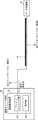
- the road monitoring system detects an abnormal state of the road 10, and includes an optical fiber cable 20 and a road monitoring device 33.
- the optical fiber cable 20 is laid along the road 10. Although the optical fiber cable 20 is laid under the road 10 in FIG. 1, it is not limited to this and may be laid on the side of the road 10 or the like. At this time, the optical fiber cables 20 may be densely installed at a position where the state of the road 10 is particularly desired to be detected, for example, by laying the optical fiber cables 20 while forming a loop. Thereby, the detection rate of abnormality of the road 10 can be improved.
- the optical fiber cable 20 is a cable formed by coating one or more communication optical fibers, and one end thereof is routed inside the communication carrier station 30.
- the road monitoring system detects an abnormal state of the road 10 by using an optical fiber sensing technology that uses an optical fiber as a sensor. Specifically, inside the communication carrier station 30, pulse light is incident on the communication optical fiber included in the optical fiber cable 20. Then, as the pulsed light is transmitted through the communication optical fiber in the direction of the road 10, backscattered light is generated for each transmission distance. The backscattered light returns to the inside of the communication carrier station building 30 via the same communication optical fiber.
- the road 10 vibrates when a landslide occurs, and the vibration of the road 10 is transmitted to the communication optical fiber. Further, the temperature of the road 10 rises when a fire or the like occurs, and the temperature change of the road 10 is also transmitted to the communication optical fiber. Further, on the road 10, when a road surface deterioration or the like occurs, a sound corresponding to the road surface deterioration is generated, and the change in the sound is also transmitted to the communication optical fiber. Therefore, in the communication optical fiber, the pattern in which the vibration, temperature, and sound of the road 10 are transmitted is the state of the road 10 (for example, whether there is an abnormality in the road surface temperature, whether landslides or rockfalls have occurred, highway, etc.).
- the backscattered light returning to the inside of the communication carrier station 30 includes a pattern according to the state of the road 10.
- the backscattered light returning to the inside of the communication carrier station 30 includes patterns corresponding to the states of various positions on the road 10.
- the road monitoring system utilizes the fact that the backscattered light returning to the inside of the communication carrier station building 30 includes a pattern corresponding to the state of the road 10, and thus the road 10 is in an abnormal state.
- abnormal road temperature, landslides and rockfalls, invasion of animals and humans into expressways, fires, earthquakes, strong winds (including typhoons and tornadoes), road surface deterioration, etc. Is detected.
- the road monitoring device 33 described above is provided inside the communication carrier station building 30.
- the road monitoring device 33 is a newly installed facility for realizing the present embodiment.
- the road monitoring device 33 is a device having a function as an optical fiber sensing device and a function of detecting an abnormal state of the road 10.
- the road monitoring device 33 includes a fiber sensing unit 331 and a detection unit 332.
- the fiber sensing unit 331 is an example of a receiving unit.
- the fiber sensing unit 331 makes pulsed light incident on at least one communication optical fiber included in the optical fiber cable 20. This pulsed light is transmitted in the direction of the road 10. Further, the fiber sensing unit 331 receives the backscattered light for the pulsed light from the same communication optical fiber as the communication optical fiber on which the pulsed light is incident. This backscattered light is received from the direction of the road 10.
- the backscattered light received by the fiber sensing unit 331 includes a pattern according to the state of the road 10. Further, in the example of FIG. 1, the fiber sensing unit 331 receives backscattered light generated at various positions on the road 10 in time series.
- the fiber sensing unit 331 when receiving the backscattered light, the fiber sensing unit 331 first identifies the position of the road 10 where the backscattered light is generated. Further, the fiber sensing unit 331 detects a vibration state, a temperature state, a sound state, etc. at the specified position. Then, the detection unit 332 detects a pattern according to the state of the identified position of the road 10 based on the processing result of the backscattered light by the fiber sensing unit 331, and based on the detected pattern, the road An abnormal state of 10 specified positions is detected.
- the fiber sensing unit 33 based on the time difference between the time when the pulsed light enters the communication optical fiber and the time when the backscattered light is received from the same communication optical fiber, the backscattering thereof.
- the position where the light is generated is specified.
- the fiber sensing unit 331 specifies the generation position so that the fiber sensing unit 331 is closer to the fiber sensing unit 331 as the above-mentioned time difference is smaller.
- the fiber sensing unit 331 performs a process of identifying the position of the road 10 in which the backscattered light received from the communication optical fiber is generated. Furthermore, the fiber sensing unit 331 detects the backscattered light with a distributed acoustic sensor, a distributed vibration sensor, a distributed temperature sensor, or the like. , The state of vibration, the state of temperature, the state of sound, etc. at the specified position of the road 10 are detected. Therefore, the detection unit 332 detects a pattern according to the state of the road 10 based on the processing result of the backscattered light by the fiber sensing unit 331.
- the detection unit 332 holds a correspondence table in which a pattern according to the state of the road 10 and the state of the road 10 are associated with each other. Therefore, when detecting the abnormal state of the road 10, the detection unit 332 first detects a pattern according to the state of the road 10. Subsequently, the detection unit 332 uses the above-mentioned correspondence table to identify the state of the road 10 corresponding to the pattern corresponding to the state of the road 10 acquired above, and thus whether the road 10 is in an abnormal state. Determine whether or not.
- a machine learning method in the method B will be described.
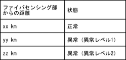
- a method will be described in which, on the road 10, a pattern at three distances from the fiber sensing unit 331, xx [km], yy [km], and zz [km], is learned as teacher data.
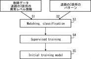
- the detection unit 332 inputs teacher data, which is abnormality level information indicating the degree of abnormality at three points on the road 10, and patterns corresponding to the states of the three points (steps S1 and S2). ).
- FIG. 3 shows an example of the abnormality level information that becomes the teacher data. Note that, in FIG. 3, the larger the numerical value of the abnormality level, the more the degree of abnormality is progressing. Further, the abnormal level information is held by the detection unit 332.
- step S5 This initial learning model is a model in which the state of the road 10 is output when a pattern according to the state of the road 10 is input.
- the detecting unit 332 When detecting the abnormal state of the road 10, the detecting unit 332 first detects a pattern according to the state of the road 10, as in the method A described above. Then, the detection unit 332 inputs the pattern into the initial learning model. Thereby, the detection unit 332 determines whether or not the road 10 is in an abnormal state because the state of the road 10 is obtained as the output result of the initial learning model.
- this method B the pattern according to the state of the road 10 is machine-learned, and the abnormal state of the road 10 is detected using the learning result of the machine learning. It may be difficult for human analysis to extract a feature for detecting the state of the road 10 from the data. In this method B, by constructing the learning model from a large number of patterns, it is possible to detect the abnormal state of the road 10 with high accuracy even if it is difficult for human analysis.
- a learning model in the initial state, may be generated based on two or more teacher data. Further, this learning model may newly learn a newly detected pattern. At that time, the detailed condition for detecting the abnormal state of the road 10 may be adjusted from the new learning model.
- the computer 40 includes a processor 401, a memory 402, a storage 403, an input/output interface (input/output I/F) 404, a communication interface (communication I/F) 405, and the like.
- the processor 401, the memory 402, the storage 403, the input/output interface 404, and the communication interface 405 are connected by a data transmission path for transmitting and receiving data mutually.
- the processor 401 is an arithmetic processing unit such as a CPU (Central Processing Unit) or a GPU (Graphics Processing Unit).
- the memory 402 is a memory such as a RAM (Random Access Memory) or a ROM (Read Only Memory).
- the storage 403 is a storage device such as a HDD (Hard Disk Drive), an SSD (Solid State Drive), or a memory card. Further, the storage 403 may be a memory such as a RAM or a ROM.
- the storage 403 stores a program that realizes the functions of the fiber sensing unit 331 and the detection unit 332 included in the road monitoring device 33.
- the processor 401 implements the functions of the fiber sensing unit 331 and the detection unit 332 by executing each of these programs.
- the processor 401 may execute these programs after reading them on the memory 402, or may execute them without reading them on the memory 402.
- the memory 402 and the storage 403 also play a role of storing information and data held by the fiber sensing unit 331 and the detection unit 332.
- Non-transitory computer readable media include various types of tangible storage media.
- Examples of non-transitory computer readable media are magnetic recording media (eg, flexible disk, magnetic tape, hard disk drive), magneto-optical recording media (eg, magneto-optical disk), CD-ROM (Compact-Disc-Read-Only Memory). , CD-R (CD-Recordable), CD-R/W (CD-ReWritable), semiconductor memory (for example, mask ROM, PROM (Programmable ROM), EPROM (Erasable PROM), flash ROM, RAM (RandomAccess Memory) )including.
- the program may be supplied to the computer by various types of transitory computer readable media.
- Examples of transitory computer-readable media include electrical signals, optical signals, and electromagnetic waves.
- the transitory computer-readable medium can supply the program to the computer via a wired communication path such as an electric wire and an optical fiber, or a wireless communication path.
- the input/output interface 404 is connected to the display device 4041, the input device 4042, and the like.
- the display device 4041 is a device such as an LCD (Liquid Crystal Display) or a CRT (Cathode Ray Tube) display that displays a screen corresponding to the drawing data processed by the processor 401.
- the input device 4042 is a device that receives an operation input of an operator, and is, for example, a keyboard, a mouse, a touch sensor, or the like.
- the display device 4041 and the input device 4042 may be integrated and realized as a touch panel.
- the computer 40 may also include sensors (not shown) including a distributed acoustic sensor, a distributed vibration sensor, and a distributed temperature sensor, and the sensor may be connected to the input/output interface 404.
- the communication interface 405 transmits/receives data to/from an external device.
- the communication interface 405 communicates with an external device via a wired communication path or a wireless communication path.
- the fiber sensing unit 331 makes pulsed light incident on at least one communication optical fiber included in the optical fiber cable 20 (step S11). Then, the fiber sensing unit 331 receives the backscattered light from the same communication optical fiber as the communication optical fiber on which the pulsed light is incident (step S12).
- the fiber sensing unit 331 identifies the position of the road 10 that generated the backscattered light received in step S12 (step S13). At this time, the fiber sensing unit 331 may specify the position where the backscattered light is generated, using the method based on the time difference described above. Further, the fiber sensing unit 331 detects a vibration state, a temperature state, a sound state, and the like at a specified position on the road 10.
- the detection unit 332 detects a pattern according to the state of the position of the road 10 specified in step S13, based on the backscattered light received in step S12. More specifically, the pattern is detected based on the processing result of the backscattered light by the fiber sensing unit 331. Then, the detection unit 332 detects an abnormal state of the position of the road 10 identified in step S13 based on the detected pattern (step S14). At this time, the detection unit 332 may detect the abnormal state by using one of the methods A and B described above.
- steps S13 and S14 may be performed each time the backscattered light is received in step S12. Alternatively, after a plurality of backscattered lights are received in step S12, the processes of steps S13 and S14 may be performed for each backscattered light.
- the backscattered light (optical signal) is received from at least one communication optical fiber included in the optical fiber cable 20, and the road 10 is received based on the received backscattered light.
- the pattern corresponding to the state of is detected, and the abnormal state of the road 10 is detected based on the detected pattern. Therefore, the abnormal state of the road 10 can be detected with high accuracy.
- the road monitoring system in order to detect the abnormal state of the road 10, it is sufficient to use an existing communication optical fiber, and as described in Patent Document 1, a steel wire for preventing external damage is used as the optical fiber cable. Need not be coated. Therefore, a dedicated structure for detecting an abnormal state of the road 10 is not required, so that the road monitoring system can be constructed at low cost.
- the optical fiber sensing technology using the optical fiber as the sensor is used. Therefore, advantages such as being unaffected by electromagnetic noise, requiring no power supply to the sensor, being excellent in environmental resistance, and facilitating maintenance are obtained.
- the detection unit 332 holds the abnormal state of the road 10 detected above for each position of the road 10 and detects the abnormal state of the position periodically (for example, every year). Then, the state change over time of the abnormal state at that position may be detected.
- the detection unit 332 may detect a sign of abnormality or breakage of the position of the road 10 based on a change in state of the position of the road 10 over time.
- the analyst may actually disassemble the portion of the position of the road 10 detected as abnormal by the detection unit 332 to determine the actual abnormality level.
- the difference may be fed back to the detection unit 332.
- the detection unit 332 subsequently detects the abnormal state of the road 10 so as to approach the actual abnormal level, so that the detection accuracy can be improved.
- the detection unit 332 machine-learns a pattern according to the state of the road 10 by the above method B, it is considered that the state of the road 10 is different depending on the area. For example, it is considered that the conditions are different between a warm region and a cold region. Therefore, the detection unit 332 may perform machine learning for each area using teacher data according to the area.
- the existing optical fiber cable 20 is used, but as shown in FIG. 7, the optical fiber cable 20 is newly installed, and the data collection unit 34 is installed in the newly installed optical fiber cable 20. May be connected.
- the data collection unit 34 also collects data on the pattern of the road 10 (for example, sound, temperature, vibration, etc.), and transmits the collected data to the detection unit 332.
- data transmission from the data collection unit 34 to the detection unit 332 may be performed via the optical fiber cable 20 or may be performed via a separately provided wireless device.
- the detection unit 332 detects an abnormal state of the road 10 based on the data collected by the data collection unit 34 and the fiber sensing unit 331. Therefore, the detection accuracy can be improved.
- a traffic control system 50 that manages the traffic of vehicles on the road 10 based on the detection result by the road monitoring device 33 may be provided.
- the traffic control system 50 is an example of a distribution unit.
- the traffic control system 50 informs the driver of the vehicle that the abnormality of the road 10 is detected by a highway radio, an information board on the road 10, the Internet, You may deliver via an application etc.
- the traffic control system 50 may deliver a warning or the like for driving the vehicle to the driver of the vehicle when an abnormal state of the road 10 is detected.
- the traffic control system 50 may deliver the road closure information to the driver of the vehicle when the road 10 in which the abnormality is detected is closed.
- the traffic control system 50 may present, to the system administrator or the like, an abnormal state of the road 10, a state change of the abnormal state of the road 10 over time, a sign of abnormal or damaged road 10, and the like. Further, the traffic control system 50 may calculate the pavement timing of the road 10 based on the detection result of the road monitoring device 33, and may present the pavement timing of the road 10 to the system administrator or the like. Further, although the traffic control system 50 is provided outside the communication carrier station building 30, a part of the functions (for example, the function of the distribution unit) may be provided inside the communication carrier station building 30. When the traffic control system 50 is provided outside the communication carrier station building 30, the single traffic control system 50 concentrates on the road 10 connected to each of the plurality of communication carrier station buildings 30 by the optical fiber cable 20. You may monitor it.
- the fiber sensing unit 331 and the detection unit 332 of the road monitoring device 33 may be provided separately from each other.
- only the fiber sensing unit 331 may be provided inside the communication carrier station 30 and the road monitoring device 33 including the detection unit 332 may be provided outside the communication carrier station 30.
- the fiber sensing unit 331 shares the optical fiber cable 20 with the existing communication equipment 31. Further, since the fiber sensing unit 331 and the existing communication equipment 31 share the optical fiber cable 20, a filter 32 for signal separation is provided.
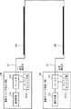
- one fiber sensing unit 331 is provided in each of the plurality of communication carrier station buildings 30 (two communication carrier station buildings 30A and 30Z in FIG. 10). Specifically, fiber sensing units 331A and 331Z are provided inside the communication carrier stations 30A and 30Z, respectively.
- the road 10A is connected to the communication carrier station 30A by the optical fiber cable 20
- the road 10B is connected to the communication carrier station 30Z by the optical fiber cable 20
- the roads 10A and 10B are connected.
- the communication equipment 31A, 31Z corresponds to the communication equipment 31
- the filters 32A, 32Z correspond to the filter 32.
- the fiber sensing units 331A and 331Z both monitor the roads 10A and 10B.
- the data collection unit 34 is provided near the road 10A.
- the roads 10A and 10B are provided for a predetermined number of roads 10 or a predetermined road length of the road 10 is provided. It is sufficient to provide one for each of them, and one or more may be provided.
- each data collection unit 34 collects data of a pattern (for example, sound, temperature, vibration, etc.) of the corresponding road 10, and the detection unit 332 collects the data collected by each data collection unit 34. Summarize. At this time, the data transmission from each data collection unit 34 to the detection unit 332 may be performed via the optical fiber cable 20 or may be performed via a separately provided wireless device. The detection unit 332 detects an abnormal state of the road 10 for which the data collection unit 34 has collected data, based on the data.
- a pattern for example, sound, temperature, vibration, etc.
- the monitoring section of one fiber sensing unit 331 is shortened, and the number of monitored roads 10 and the road length are reduced. Since the monitoring section of the fiber sensing unit 331 is short, the transmission distance of the pulsed light and the backscattered light is short, and the fiber loss is small. Thereby, the S/N ratio (signal-to-noise ratio) of the received backscattered light is improved, and the monitor accuracy can be improved. Further, the number of roads 10 to be monitored by the fiber sensing unit 331 and the length of the roads are reduced, so that the monitoring cycle can be improved.
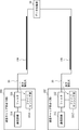
- one communication carrier station 30AZ is provided with a plurality of fiber sensing units 331 (two fiber sensing units 331A and 331Z in FIG. 12).
- the road 10A is connected to the fiber sensing unit 331A by the optical fiber cable 20
- the road 10B is connected to the fiber sensing unit 331Z by the optical fiber cable 20
- the roads 10A and 10B are optical. It is connected by a fiber cable 20.
- the communication equipment 31A, 31Z corresponds to the communication equipment 31, and the filters 32A, 32Z correspond to the filter 32.
- the fiber sensing units 331A and 331Z both monitor the roads 10A and 10B.
- the fiber sensing unit 331A enters the pulsed light in the clockwise direction to monitor the roads 10A and 10B
- the fiber sensing unit 331Z enters the pulsed light in the counterclockwise direction to detect the roads 10A and 10B. Monitor 10B.
- one road monitoring device 33 including a detection unit 332 may be provided for the plurality of fiber sensing units 331. Then, the state of the road 10 connected to each of the plurality of fiber sensing units 331 by the optical fiber cable 20 may be intensively detected by one road monitoring device 33.
- the road monitoring device 33 may be provided inside any one of the communication carrier station buildings 30 or outside the communication carrier station buildings 30.
- the optical fiber cable 20 laid on the road 10 may be broken. Therefore, the operation of the fiber sensing unit 331 when the optical fiber cable 20 is disconnected in the road monitoring system according to another embodiment will be described with reference to FIGS. 13 to 15. Note that the detection unit 332 is not shown in FIGS. 13 to 15.
- FIG. 13 is an example in which the optical fiber cable 20 of the road 10 is broken in the configuration of FIG.
- the fiber sensing unit 331 keeps the pulsed light incident on the optical fiber cable 20 even when the optical fiber cable 20 is broken.
- the communication carrier station 30 can continuously monitor the section up to the disconnected position.
- FIG. 14 is an example in which the optical fiber cable 20 of the road 10A is broken in the configuration of FIG.
- the fiber sensing units 331A and 331Z keep the pulsed light incident on the optical fiber cable 20 even when the optical fiber cable 20 is broken.
- the road 10 is always connected to two or more communication carrier station buildings 30 (two communication carrier station buildings 30A and 30Z in FIG. 14). Therefore, by the communication carrier stations 30A and 30Z monitoring in both directions, it is possible to construct a redundant configuration capable of continuously monitoring the entire section in the case of a single failure.
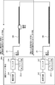
- the example of FIG. 15 is an example in which the optical fiber cable 20 of the road 10A is broken in the configuration of FIG.
- the fiber sensing units 331A and 331Z keep the pulsed light incident on the optical fiber cable 20 even when the optical fiber cable 20 is broken.
- a ring configuration in which the optical fiber cables 20 are connected in a ring shape is constructed. Therefore, by monitoring from one communication carrier station 30AZ bidirectionally in the ring, it is possible to construct a redundant configuration capable of continuously monitoring the entire section in the case of a single failure.
- a cable including a communication optical fiber laid on the road A receiving unit for receiving an optical signal from at least one communication optical fiber included in the cable, Based on the optical signal, detects a pattern according to the state of the road, based on the pattern according to the detected state of the road, a detection unit for detecting an abnormal state of the road, Road monitoring system.
- the receiving unit Based on the optical signal, to identify the position of the road where the optical signal is generated, The detection unit, Based on a pattern according to the detected state of the road, to detect an abnormal state of the specified position of the road, The road monitoring system according to attachment 1.
- the detected information of the abnormal state of the road is further provided with a distribution unit that distributes to the driver of the vehicle, The road monitoring system according to appendix 1 or 2.
- the receiving unit Based on the optical signal, to identify the position of the road where the optical signal is generated, The detection unit, Based on a pattern according to the detected state of the road, to detect an abnormal state of the specified position of the road, The road monitoring device according to attachment 4.
- a road monitoring method using a road monitoring device Receiving an optical signal from at least one communication optical fiber included in a cable laid on the road, Based on the optical signal, to detect a pattern according to the state of the road, based on the pattern according to the detected state of the road, to detect an abnormal state of the road, Road monitoring method.
Landscapes
- Physics & Mathematics (AREA)
- General Physics & Mathematics (AREA)
- Chemical & Material Sciences (AREA)
- Analytical Chemistry (AREA)
- Life Sciences & Earth Sciences (AREA)
- Atmospheric Sciences (AREA)
- Traffic Control Systems (AREA)
- Optical Transform (AREA)
Abstract
Description
そのため、最近は、道路の異常を、光ファイバを用いて監視するシステムが提案されている(例えば、特許文献1)。 Conventionally, road abnormality detection is often performed manually, and for example, a worker visually or using a thermography camera or the like monitors road surface temperature abnormality (for example, road surface freezing, etc.), They used visual observation or a camera to monitor the occurrence of landslides and the intrusion of animals and humans into expressways. However, when a road abnormality is detected manually, it takes a lot of time and cost, and the detection and handling of the abnormality may be delayed.
Therefore, recently, a system for monitoring a road abnormality using an optical fiber has been proposed (for example, Patent Document 1).
したがって、道路への落石等の極端な状態は検出することができるものの、光ファイバへの応力にほとんど影響しないような状態の検出は困難であるという課題がある。 In the technique described in Patent Document 1, a road abnormality is detected by monitoring the polarization state of an optical signal when strong stress is applied to an optical fiber.
Therefore, although an extreme state such as a rock fall on the road can be detected, there is a problem that it is difficult to detect a state that hardly affects the stress on the optical fiber.
道路に敷設された通信用光ファイバを含むケーブルと、
前記ケーブルに含まれる少なくとも1つの通信用光ファイバから、光信号を受信する受信部と、
前記光信号に基づいて、前記道路の状態に応じたパターンを検出し、検出された前記道路の状態に応じたパターンに基づいて、前記道路の異常状態を検出する検出部と、
を備える。 A road monitoring system according to one aspect,
A cable including a communication optical fiber laid on the road,
A receiving unit for receiving an optical signal from at least one communication optical fiber included in the cable,
Based on the optical signal, detects a pattern according to the state of the road, based on the pattern according to the detected state of the road, a detection unit for detecting an abnormal state of the road,
Equipped with.
道路に敷設されたケーブルに含まれる少なくとも1つの通信用光ファイバから、光信号を受信する受信部と、
前記光信号に基づいて、前記道路の状態に応じたパターンを検出し、検出された前記道路の状態に応じたパターンに基づいて、前記道路の異常状態を検出する検出部と、
を備える。 The road monitoring device according to one aspect,
A receiver for receiving an optical signal from at least one communication optical fiber included in a cable laid on a road;
Based on the optical signal, detects a pattern according to the state of the road, based on the pattern according to the detected state of the road, a detection unit for detecting an abnormal state of the road,
Equipped with.
道路監視装置による道路監視方法であって、
道路に敷設されたケーブルに含まれる少なくとも1つの通信用光ファイバから、光信号を受信し、
前記光信号に基づいて、前記道路の状態に応じたパターンを検出し、検出された前記道路の状態に応じたパターンに基づいて、前記道路の異常状態を検出する。 A road monitoring method according to one aspect,
A road monitoring method using a road monitoring device,
Receiving an optical signal from at least one communication optical fiber included in a cable laid on the road,
A pattern according to the state of the road is detected based on the optical signal, and an abnormal state of the road is detected based on the pattern according to the detected state of the road.
コンピュータに、
道路に敷設されたケーブルに含まれる少なくとも1つの通信用光ファイバから、光信号を受信する手順と、
前記光信号に基づいて、前記道路の状態に応じたパターンを検出し、検出された前記道路の状態に応じたパターンに基づいて、前記道路の異常状態を検出する手順と、
を実行させるためのプログラムを格納した非一時的なコンピュータ可読媒体である。 A non-transitory computer-readable medium according to one aspect comprises
On the computer,
A procedure for receiving an optical signal from at least one communication optical fiber included in a cable laid on a road;
Based on the optical signal, to detect a pattern according to the state of the road, based on the pattern according to the detected state of the road, a procedure for detecting an abnormal state of the road,
It is a non-transitory computer-readable medium that stores a program for executing.
<実施の形態>
<実施の形態の構成>
まず、図1を参照して、本実施の形態に係る道路監視システムの構成について説明する。 Hereinafter, embodiments of the present disclosure will be described with reference to the drawings.
<Embodiment>
<Structure of Embodiment>
First, the configuration of the road monitoring system according to the present embodiment will be described with reference to FIG.
光ファイバケーブル20は、1以上の通信用光ファイバを被覆して構成されるケーブルであり、一端は通信キャリア局舎30の内部に引き回されている。 The
The
具体的には、通信キャリア局舎30の内部では、光ファイバケーブル20に含まれる通信用光ファイバにパルス光を入射する。すると、パルス光が道路10の方向に通信用光ファイバを伝送されることに伴い、伝送距離毎に後方散乱光が発生する。この後方散乱光は、同じ通信用光ファイバを経由して通信キャリア局舎30の内部に戻ってくる。 The road monitoring system according to the present embodiment detects an abnormal state of the
Specifically, inside the
その上で、検出部332は、ファイバセンシング部331による後方散乱光の処理結果に基づいて、道路10の特定された位置の状態に応じたパターンを検出し、検出されたパターンに基づいて、道路10の特定された位置の異常状態を検出する。 Therefore, when receiving the backscattered light, the
Then, the
(A)方法A
まず、道路10の異常状態を検出する方法Aについて説明する。
ファイバセンシング部331は、通信用光ファイバから受信された後方散乱光が発生した道路10の位置を特定する処理を行う。さらに、ファイバセンシング部331は、その後方散乱光を分散型音響センサ(Distributed Acoustic Sensor)、分散型振動センサ(Distributed Vibration Sensor)、及び分散型温度センサ(Distributed Temperature Sensor)等にて検出することで、道路10の特定された位置での振動の状態、温度の状態、音の状態等を検出する処理を行う。
そのため、検出部332は、ファイバセンシング部331による後方散乱光の処理結果に基づいて、道路10の状態に応じたパターンを検出する。 Subsequently, a method of detecting an abnormal state of the
(A) Method A
First, a method A for detecting an abnormal state of the
The
Therefore, the
続いて、道路10の異常状態を検出する方法Bについて説明する。
本方法Bでは、検出部332は、道路10の状態に応じたパターンを機械学習(例えば、深層学習等)し、機械学習の学習結果(初期学習モデル)を用いて、道路10の異常状態を検出する。 (B) Method B
Subsequently, a method B for detecting an abnormal state of the
In this method B, the
図2に示されるように、検出部332は、道路10の3箇所の異常度合いを示す異常レベル情報である教師データと、3箇所の状態に応じたパターンと、を入力する(ステップS1,S2)。図3に、教師データとなる異常レベル情報の一例を示す。なお、図3において、異常レベルは、数値が大きいほど、異常度合いが進行していることを示している。また、異常レベル情報は、検出部332が保持する。 First, with reference to FIG. 2, a machine learning method in the method B will be described. Here, a method will be described in which, on the
As shown in FIG. 2, the
検出部332は、道路10の異常状態を検出する場合、上述の方法Aと同様に、まず、道路10の状態に応じたパターンを検出する。続いて、検出部332は、そのパターンを初期学習モデルに入力する。これにより、検出部332は、初期学習モデルの出力結果として、道路10の状態が得られるため、道路10が異常状態であるか否かを判定する。 Subsequently, a method of detecting an abnormal state of the
When detecting the abnormal state of the
データから道路10の状態を検出するための特徴を抽出することが、人間による解析では困難な場合がある。本方法Bでは、大量のパターンから学習モデルを構築することにより、人間での解析では困難であった場合でも、道路10の異常状態を高精度に検出することができる。 As described above, in this method B, the pattern according to the state of the
It may be difficult for human analysis to extract a feature for detecting the state of the
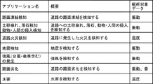
検出部332により検出された道路10の異常状態に基づいて、例えば、以下の(a)~(g)のアプリケーションを実現することが可能である。以下、各アプリケーションについて説明する。 Subsequently, an application that can be realized based on the abnormal state of the
Based on the abnormal state of the
課題及び効果:
道路10の路面凍結は、交通事故につながる可能性があるため、どの区間でどこまで路面が凍結しているのか適切に把握することが必要となる。
動作概要:
道路10の表面温度を、道路10の下に敷設された光ファイバケーブル20を介してモニタし、特定温度以下の場合を路面凍結として検知する。 (A) Road surface freezing detection Issues and effects:
The freezing of the road surface of the
Operation overview:
The surface temperature of the
課題及び効果:
土砂崩れ、落石の発生及び動物や人間等の侵入等をリモートからリアルタイムで検知することにより、車両(自動車)の運転者への適切な通知、危険区域への対処を迅速に行うことが可能となる。
動作概要:
土砂崩れ、落石、動物や人間等の侵入等で発生する振動を、道路10の下に敷設された光ファイバケーブル20を介してモニタし、振動のパターンの特徴により異常を検知する。
また、フェンスや山の斜面へ光ファイバケーブル20を敷設する形態でも良い。 (B) Landslides, rockfall detection, intrusion detection of animals and humans Challenges and effects:
By remotely detecting the occurrence of landslides, falling rocks, and invasion of animals, humans, etc., in real time, it is possible to appropriately notify the driver of the vehicle (automobile) and quickly deal with the dangerous area. .
Operation overview:
Vibrations caused by landslides, rockfalls, invasion of animals, humans, etc. are monitored through an
Alternatively, the
課題及び効果:
火災が発生した状況をリモートからリアルタイムでモニタすることにより、迅速な消化活動が可能となる。
動作概要:
道路10の表面温度を、道路10の下に敷設された光ファイバケーブル20を介してモニタし、特定温度以上であった場合を火災として検知する。 (C) Road fire detection Issues and effects:
By remotely monitoring the situation of a fire in real time, it is possible to carry out a quick digestion activity.
Operation overview:
The surface temperature of the
課題及び効果:
広域の振動状況をモニタすることにより、地震の発生位置及び地震の伝搬を把握することが可能となる。地震の速報や迅速な状況把握することが可能となる。
動作概要:
道路10に埋設された光ファイバケーブル20の振動をモニタし、広域の振動状況を分析することにより震源地や地震到達速度を検知する。 (D) Earthquake detection Issues and effects:
By monitoring the vibration conditions in a wide area, it becomes possible to grasp the location of the earthquake and the propagation of the earthquake. It will be possible to get a quick report of the earthquake and a quick grasp of the situation.
Operation overview:
The vibration of the
課題及び効果:
道路10全体の風速をリモートから検知することにより、危険区域への車両の進行を回避する。
動作概要:
道路10沿いに敷設された光ファイバケーブル20の振動から風速をモニタする。
風速が閾値を超えた場合を強風として検知する。 (E) Generation of strong winds (including typhoons and tornados) Issues and effects:
By remotely detecting the wind speed of the
Operation overview:
The wind speed is monitored from the vibration of the
When the wind speed exceeds the threshold value, it is detected as a strong wind.
課題及び効果:
道路10全域で路面のひび割れ、劣化状態を監視することにより、人手で行っていた検査の軽減が可能となる。
動作概要:
道路10で発生した音や振動をモニタする。
振動のパターンの特徴により路面劣化を検知する。 (F) Road surface deterioration
Issues and effects:
By monitoring cracks and deterioration of the road surface in the entire area of the
Operation overview:
Sounds and vibrations generated on the
Road surface deterioration is detected by the characteristics of the vibration pattern.
課題及び効果:
道路10全体の水害状況をリモートから検知することにより、危険区域への車両の進行を回避する。
動作概要:
道路10全体の温度状況から温度の変化が顕著に変化している位置を特定し、特定された位置に水害が発生していると判定する。 (G) Water damage Issues and effects:
By remotely detecting the water damage condition of the
Operation overview:
From the temperature condition of the
図5に示されるように、コンピュータ40は、プロセッサ401、メモリ402、ストレージ403、入出力インタフェース(入出力I/F)404、及び通信インタフェース(通信I/F)405などを備える。プロセッサ401、メモリ402、ストレージ403、入出力インタフェース404、及び通信インタフェース405は、相互にデータを送受信するためのデータ伝送路で接続されている。 Subsequently, the hardware configuration of the
As shown in FIG. 5, the
以下、本実施の形態に係る道路監視システムの動作について説明する。ここでは、図6を参照して、本実施の形態に係る道路監視システムの動作フローについて説明する。 <Operation of Embodiment>
The operation of the road monitoring system according to this embodiment will be described below. Here, the operation flow of the road monitoring system according to the present embodiment will be described with reference to FIG.
続いて、ファイバセンシング部331は、パルス光を入射した通信用光ファイバと同じ通信用光ファイバから後方散乱光を受信する(ステップS12)。 As shown in FIG. 6, first, the
Then, the
上述したように本実施の形態によれば、光ファイバケーブル20に含まれる少なくとも1つの通信用光ファイバから後方散乱光(光信号)を受信し、受信された後方散乱光に基づいて、道路10の状態に応じたパターンを検出し、検出されたパターンに基づいて、道路10の異常状態を検出する。そのため、道路10の異常状態を高精度に検出することができる。 <Effects of the embodiment>
As described above, according to the present embodiment, the backscattered light (optical signal) is received from at least one communication optical fiber included in the
なお、検出部332は、道路10の位置毎に、上記で検出された道路10の異常状態を保持することとし、定期的に(例えば、1年毎)、その位置の異常状態を検出することで、その位置の異常状態の経時的な状態変化を検出しても良い。 <Other Embodiments>
The
図10の例では、ファイバセンシング部331A,331Zが共に、道路10A,10Bをモニタする。 In the example of FIG. 10, one
In the example of FIG. 10, the
(付記1)
道路に敷設された通信用光ファイバを含むケーブルと、
前記ケーブルに含まれる少なくとも1つの通信用光ファイバから、光信号を受信する受信部と、
前記光信号に基づいて、前記道路の状態に応じたパターンを検出し、検出された前記道路の状態に応じたパターンに基づいて、前記道路の異常状態を検出する検出部と、
を備える道路監視システム。
(付記2)
前記受信部は、
前記光信号に基づいて、前記光信号が発生した前記道路の位置を特定し、
前記検出部は、
前記検出された前記道路の状態に応じたパターンに基づいて、前記特定された前記道路の位置の異常状態を検出する、
付記1に記載の道路監視システム。
(付記3)
前記検出された前記道路の異常状態の情報を、車両の運転者に配信する配信部をさらに備える、
付記1又は2に記載の道路監視システム。
(付記4)
道路に敷設されたケーブルに含まれる少なくとも1つの通信用光ファイバから、光信号を受信する受信部と、
前記光信号に基づいて、前記道路の状態に応じたパターンを検出し、検出された前記道路の状態に応じたパターンに基づいて、前記道路の異常状態を検出する検出部と、
を備える道路監視装置。
(付記5)
前記受信部は、
前記光信号に基づいて、前記光信号が発生した前記道路の位置を特定し、
前記検出部は、
前記検出された前記道路の状態に応じたパターンに基づいて、前記特定された前記道路の位置の異常状態を検出する、
付記4に記載の道路監視装置。
(付記6)
道路監視装置による道路監視方法であって、
道路に敷設されたケーブルに含まれる少なくとも1つの通信用光ファイバから、光信号を受信し、
前記光信号に基づいて、前記道路の状態に応じたパターンを検出し、検出された前記道路の状態に応じたパターンに基づいて、前記道路の異常状態を検出する、
道路監視方法。
(付記7)
コンピュータに、
道路に敷設されたケーブルに含まれる少なくとも1つの通信用光ファイバから、光信号を受信する手順と、
前記光信号に基づいて、前記道路の状態に応じたパターンを検出し、検出された前記道路の状態に応じたパターンに基づいて、前記道路の異常状態を検出する手順と、
を実行させるためのプログラムを格納した非一時的なコンピュータ可読媒体。 The whole or part of the exemplary embodiments disclosed above can be described as, but not limited to, the following supplementary notes.
(Appendix 1)
A cable including a communication optical fiber laid on the road,
A receiving unit for receiving an optical signal from at least one communication optical fiber included in the cable,
Based on the optical signal, detects a pattern according to the state of the road, based on the pattern according to the detected state of the road, a detection unit for detecting an abnormal state of the road,
Road monitoring system.
(Appendix 2)
The receiving unit,
Based on the optical signal, to identify the position of the road where the optical signal is generated,
The detection unit,
Based on a pattern according to the detected state of the road, to detect an abnormal state of the specified position of the road,
The road monitoring system according to attachment 1.
(Appendix 3)
The detected information of the abnormal state of the road is further provided with a distribution unit that distributes to the driver of the vehicle,
The road monitoring system according to appendix 1 or 2.
(Appendix 4)
A receiver for receiving an optical signal from at least one communication optical fiber included in a cable laid on a road;
Based on the optical signal, to detect a pattern according to the state of the road, based on the pattern according to the detected state of the road, a detection unit for detecting an abnormal state of the road,
Road monitoring device.
(Appendix 5)
The receiving unit,
Based on the optical signal, to identify the position of the road where the optical signal is generated,
The detection unit,
Based on a pattern according to the detected state of the road, to detect an abnormal state of the specified position of the road,
The road monitoring device according to attachment 4.
(Appendix 6)
A road monitoring method using a road monitoring device,
Receiving an optical signal from at least one communication optical fiber included in a cable laid on the road,
Based on the optical signal, to detect a pattern according to the state of the road, based on the pattern according to the detected state of the road, to detect an abnormal state of the road,
Road monitoring method.
(Appendix 7)
On the computer,
A procedure for receiving an optical signal from at least one communication optical fiber included in a cable laid on a road;
Based on the optical signal, to detect a pattern according to the state of the road, based on the pattern according to the detected state of the road, a procedure for detecting an abnormal state of the road,
A non-transitory computer-readable medium that stores a program for executing.
20 光ファイバケーブル
30,30A,30Z,30AZ 通信キャリア局舎
31,31A,31Z 通信設備
32,32A,32Z フィルタ
33 道路監視装置
331,331A,331Z ファイバセンシング部
332 検出部
34 データ収集部
40 コンピュータ
401 プロセッサ
402 メモリ
403 ストレージ
404 入出力インタフェース
4041 表示装置
4042 入力装置
405 通信インタフェース
50 交通管制システム 10, 10A,
Claims (7)
- 道路に敷設された通信用光ファイバを含むケーブルと、
前記ケーブルに含まれる少なくとも1つの通信用光ファイバから、光信号を受信する受信部と、
前記光信号に基づいて、前記道路の状態に応じたパターンを検出し、検出された前記道路の状態に応じたパターンに基づいて、前記道路の異常状態を検出する検出部と、
を備える道路監視システム。 A cable including a communication optical fiber laid on the road,
A receiving unit for receiving an optical signal from at least one communication optical fiber included in the cable,
Based on the optical signal, detects a pattern according to the state of the road, based on the pattern according to the detected state of the road, a detection unit for detecting an abnormal state of the road,
Road monitoring system. - 前記受信部は、
前記光信号に基づいて、前記光信号が発生した前記道路の位置を特定し、
前記検出部は、
前記検出された前記道路の状態に応じたパターンに基づいて、前記特定された前記道路の位置の異常状態を検出する、
請求項1に記載の道路監視システム。 The receiving unit,
Based on the optical signal, to identify the position of the road where the optical signal is generated,
The detection unit,
Based on a pattern according to the detected state of the road, to detect an abnormal state of the specified position of the road,
The road monitoring system according to claim 1. - 前記検出された前記道路の異常状態の情報を、車両の運転者に配信する配信部をさらに備える、
請求項1又は2に記載の道路監視システム。 The detected information of the abnormal state of the road is further provided with a distribution unit that distributes to the driver of the vehicle,
The road monitoring system according to claim 1. - 道路に敷設されたケーブルに含まれる少なくとも1つの通信用光ファイバから、光信号を受信する受信部と、
前記光信号に基づいて、前記道路の状態に応じたパターンを検出し、検出された前記道路の状態に応じたパターンに基づいて、前記道路の異常状態を検出する検出部と、
を備える道路監視装置。 A receiver for receiving an optical signal from at least one communication optical fiber included in a cable laid on a road;
Based on the optical signal, detects a pattern according to the state of the road, based on the pattern according to the detected state of the road, a detection unit for detecting an abnormal state of the road,
Road monitoring device. - 前記受信部は、
前記光信号に基づいて、前記光信号が発生した前記道路の位置を特定し、
前記検出部は、
前記検出された前記道路の状態に応じたパターンに基づいて、前記特定された前記道路の位置の異常状態を検出する、
請求項4に記載の道路監視装置。 The receiving unit,
Based on the optical signal, to identify the position of the road where the optical signal is generated,
The detection unit,
Based on a pattern according to the detected state of the road, to detect an abnormal state of the specified position of the road,
The road monitoring device according to claim 4. - 道路監視装置による道路監視方法であって、
道路に敷設されたケーブルに含まれる少なくとも1つの通信用光ファイバから、光信号を受信し、
前記光信号に基づいて、前記道路の状態に応じたパターンを検出し、検出された前記道路の状態に応じたパターンに基づいて、前記道路の異常状態を検出する、
道路監視方法。 A road monitoring method using a road monitoring device,
Receiving an optical signal from at least one communication optical fiber included in a cable laid on the road,
Based on the optical signal, to detect a pattern according to the state of the road, based on the pattern according to the detected state of the road, to detect an abnormal state of the road,
Road monitoring method. - コンピュータに、
道路に敷設されたケーブルに含まれる少なくとも1つの通信用光ファイバから、光信号を受信する手順と、
前記光信号に基づいて、前記道路の状態に応じたパターンを検出し、検出された前記道路の状態に応じたパターンに基づいて、前記道路の異常状態を検出する手順と、
を実行させるためのプログラムを格納した非一時的なコンピュータ可読媒体。 On the computer,
A procedure for receiving an optical signal from at least one communication optical fiber included in a cable laid on a road;
Based on the optical signal, to detect a pattern according to the state of the road, based on the pattern according to the detected state of the road, a procedure for detecting an abnormal state of the road,
A non-transitory computer-readable medium that stores a program for executing.
Priority Applications (6)
| Application Number | Priority Date | Filing Date | Title |
|---|---|---|---|
| US17/299,049 US20220044552A1 (en) | 2018-12-06 | 2019-10-16 | Road monitoring system, road monitoring device, road monitoring method, and non-transitory computer-readable medium |
| JP2020559765A JPWO2020116032A1 (en) | 2018-12-06 | 2019-10-16 | Road monitoring systems, road monitoring devices, road monitoring methods, and programs |
| CN201980091147.7A CN113366545A (en) | 2018-12-06 | 2019-10-16 | Road monitoring system, road monitoring device, road monitoring method, and non-transitory computer readable medium |
| MX2021006516A MX2021006516A (en) | 2018-12-06 | 2019-10-16 | Road monitoring system, road monitoring device, road monitoring method, and non-transitory computer-readable medium. |
| EP19893897.9A EP3893216A4 (en) | 2018-12-06 | 2019-10-16 | Road monitoring system, road monitoring device, road monitoring method, and non-transitory computer-readable medium |
| JP2023194247A JP2024014948A (en) | 2018-12-06 | 2023-11-15 | Road monitoring system, road monitoring device, road monitoring method, and program |
Applications Claiming Priority (2)
| Application Number | Priority Date | Filing Date | Title |
|---|---|---|---|
| JP2018-229185 | 2018-12-06 | ||
| JP2018229185 | 2018-12-06 |
Publications (1)
| Publication Number | Publication Date |
|---|---|
| WO2020116032A1 true WO2020116032A1 (en) | 2020-06-11 |
Family
ID=70974532
Family Applications (1)
| Application Number | Title | Priority Date | Filing Date |
|---|---|---|---|
| PCT/JP2019/040708 WO2020116032A1 (en) | 2018-12-06 | 2019-10-16 | Road monitoring system, road monitoring device, road monitoring method, and non-transitory computer-readable medium |
Country Status (6)
| Country | Link |
|---|---|
| US (1) | US20220044552A1 (en) |
| EP (1) | EP3893216A4 (en) |
| JP (2) | JPWO2020116032A1 (en) |
| CN (1) | CN113366545A (en) |
| MX (1) | MX2021006516A (en) |
| WO (1) | WO2020116032A1 (en) |
Cited By (6)
| Publication number | Priority date | Publication date | Assignee | Title |
|---|---|---|---|---|
| JP2022020231A (en) * | 2020-07-20 | 2022-02-01 | 日本電信電話株式会社 | Optical fiber cable sensing system, optical fiber cable sensing method, and optical fiber cable |
| JP2022020232A (en) * | 2020-07-20 | 2022-02-01 | 日本電信電話株式会社 | Optical fiber cable sensing device, optical fiber cable sensing method, and program |
| WO2022113164A1 (en) * | 2020-11-24 | 2022-06-02 | 日本電気株式会社 | Optical fiber sensing system, optical fiber sensing method, and optical fiber sensing device |
| US11754424B2 (en) | 2021-09-30 | 2023-09-12 | Fujitsu Limited | Computer-readable non-transitory medium, estimation device and estimation method |
| WO2024157489A1 (en) * | 2023-01-27 | 2024-08-02 | 日本電信電話株式会社 | Abnormality monitoring system, abnormality monitoring method, computation device, and program |
| JP7555496B2 (en) | 2021-01-15 | 2024-09-24 | エヌイーシー ラボラトリーズ アメリカ インク | Road traffic extraction for unknown anomaly detection using distributed optical fiber sensing |
Families Citing this family (2)
| Publication number | Priority date | Publication date | Assignee | Title |
|---|---|---|---|---|
| JP2023050257A (en) * | 2021-09-30 | 2023-04-11 | 富士通株式会社 | Abnormality detection program, abnormality detector, and method for detecting abnormality |
| CN116895147B (en) * | 2023-06-21 | 2024-03-12 | 清华大学 | Road condition monitoring method, device, sensor and computer equipment |
Citations (4)
| Publication number | Priority date | Publication date | Assignee | Title |
|---|---|---|---|---|
| JP2000180219A (en) | 1998-12-10 | 2000-06-30 | Hitachi Cable Ltd | Rock fall detecting system |
| JP2001221684A (en) * | 2000-02-08 | 2001-08-17 | Fujikura Ltd | Method and apparatus for detection and judgment of vibration using optical fiber cable, and as system for detection and judgment of vibration |
| JP2003232043A (en) * | 2002-02-06 | 2003-08-19 | Oki Electric Ind Co Ltd | Detector for abnormal soil, detection system for abnormal soil, and its detection method |
| JP2014222485A (en) * | 2013-05-14 | 2014-11-27 | 株式会社東芝 | Information display board |
Family Cites Families (28)
| Publication number | Priority date | Publication date | Assignee | Title |
|---|---|---|---|---|
| US5457994A (en) * | 1992-11-06 | 1995-10-17 | Southwest Research Institute | Nondestructive evaluation of non-ferromagnetic materials using magnetostrictively induced acoustic/ultrasonic waves and magnetostrictively detected acoustic emissions |
| FI108084B (en) * | 1995-09-08 | 2001-11-15 | Vaisala Oyj | Method and apparatus for measuring road surface characteristics |
| JPH09166666A (en) * | 1995-12-19 | 1997-06-24 | Hitachi Cable Ltd | Estimation method for freezing of road surface |
| JP3528435B2 (en) * | 1996-06-27 | 2004-05-17 | トヨタ自動車株式会社 | Road object detection device |
| JP2001296189A (en) * | 2000-04-14 | 2001-10-26 | Sumitomo Electric Ind Ltd | System for measuring road surface temperature |
| JP2003307564A (en) * | 2002-02-15 | 2003-10-31 | Mitsubishi Electric Corp | Inclination angle measuring instrument |
| US20080125984A1 (en) * | 2006-09-25 | 2008-05-29 | Veselin Skendzic | Spatially Assisted Fault Reporting Method, System and Apparatus |
| CN101706997A (en) * | 2009-08-17 | 2010-05-12 | 昆山敏通光纤传感技术研发中心有限公司 | Distributed optical fiber vehicle comprehensive information detection system and processing method thereof |
| CN101915606B (en) * | 2010-07-27 | 2012-02-22 | 南京信息工程大学 | Device and method for detecting icy pavement of highway |
| EP2828781B1 (en) * | 2012-03-22 | 2019-05-08 | Tata Consultancy Services Limited | A system and a method for improved car prognosis |
| US10499477B2 (en) * | 2013-03-18 | 2019-12-03 | Signify Holding B.V. | Methods and apparatus for information management and control of outdoor lighting networks |
| GB201507114D0 (en) * | 2015-04-27 | 2015-06-10 | Fotech Solutions Ltd | Distributed optical fibre sensor |
| US20160328654A1 (en) * | 2015-05-04 | 2016-11-10 | Agt International Gmbh | Anomaly detection for context-dependent data |
| US10229231B2 (en) * | 2015-09-11 | 2019-03-12 | Ford Global Technologies, Llc | Sensor-data generation in virtual driving environment |
| GB201519202D0 (en) * | 2015-10-30 | 2015-12-16 | Optasense Holdings Ltd | Monitoring traffic flow |
| CN105740802A (en) * | 2016-01-28 | 2016-07-06 | 北京中科慧眼科技有限公司 | Disparity map-based obstacle detection method and device as well as automobile driving assistance system |
| NL2016744B1 (en) * | 2016-05-09 | 2017-11-16 | Fugro Tech Bv | Fiber-optic based traffic and infrastructure monitoring system |
| US20170349148A1 (en) * | 2016-06-03 | 2017-12-07 | GM Global Technology Operations LLC | Method and apparatus for detecting road condition data and weather condition data using vehicular crowd-sensing |
| CN109477906B (en) * | 2016-06-30 | 2022-04-12 | 株式会社普利司通 | Road surface state discrimination method and road surface state discrimination device |
| JP6620787B2 (en) * | 2016-08-11 | 2019-12-18 | 株式会社デンソー | Road surface condition estimation device |
| CN106600979A (en) * | 2016-12-20 | 2017-04-26 | 浙江中电智能科技有限公司 | Traffic status monitoring system and monitoring method based on distributed fiber sensor |
| GB2558294B (en) * | 2016-12-23 | 2020-08-19 | Aiq Dienstleistungen Ug Haftungsbeschraenkt | Calibrating a distributed fibre optic sensing system |
| WO2018122586A1 (en) * | 2016-12-30 | 2018-07-05 | 同济大学 | Method of controlling automated driving speed based on comfort level |
| CN107425906B (en) * | 2017-07-25 | 2019-09-27 | 电子科技大学 | Distributing optical fiber sensing signal processing method towards underground pipe network safety monitoring |
| BR102017017613B1 (en) * | 2017-08-16 | 2023-12-26 | Velsis Sistemas E Tecnologia Viaria S/A | DYNAMIC WEIGHING AND VEHICLE SPEED MONITORING SYSTEM ON TRACK |
| US10719720B2 (en) * | 2017-12-18 | 2020-07-21 | Korea Institute Of Civil Engineering And Building Technology | Artificial intelligence system for providing road surface risk information and method thereof |
| US10696257B2 (en) * | 2018-07-17 | 2020-06-30 | Denso International America, Inc. | Automatic crowd sensing and reporting system for road incidents |
| US11421974B2 (en) * | 2018-07-20 | 2022-08-23 | Teijin Limited | Sensor device with improved stability |
-
2019
- 2019-10-16 CN CN201980091147.7A patent/CN113366545A/en active Pending
- 2019-10-16 EP EP19893897.9A patent/EP3893216A4/en active Pending
- 2019-10-16 WO PCT/JP2019/040708 patent/WO2020116032A1/en active Application Filing
- 2019-10-16 MX MX2021006516A patent/MX2021006516A/en unknown
- 2019-10-16 US US17/299,049 patent/US20220044552A1/en not_active Abandoned
- 2019-10-16 JP JP2020559765A patent/JPWO2020116032A1/en active Pending
-
2023
- 2023-11-15 JP JP2023194247A patent/JP2024014948A/en active Pending
Patent Citations (4)
| Publication number | Priority date | Publication date | Assignee | Title |
|---|---|---|---|---|
| JP2000180219A (en) | 1998-12-10 | 2000-06-30 | Hitachi Cable Ltd | Rock fall detecting system |
| JP2001221684A (en) * | 2000-02-08 | 2001-08-17 | Fujikura Ltd | Method and apparatus for detection and judgment of vibration using optical fiber cable, and as system for detection and judgment of vibration |
| JP2003232043A (en) * | 2002-02-06 | 2003-08-19 | Oki Electric Ind Co Ltd | Detector for abnormal soil, detection system for abnormal soil, and its detection method |
| JP2014222485A (en) * | 2013-05-14 | 2014-11-27 | 株式会社東芝 | Information display board |
Non-Patent Citations (1)
| Title |
|---|
| See also references of EP3893216A4 |
Cited By (8)
| Publication number | Priority date | Publication date | Assignee | Title |
|---|---|---|---|---|
| JP2022020231A (en) * | 2020-07-20 | 2022-02-01 | 日本電信電話株式会社 | Optical fiber cable sensing system, optical fiber cable sensing method, and optical fiber cable |
| JP2022020232A (en) * | 2020-07-20 | 2022-02-01 | 日本電信電話株式会社 | Optical fiber cable sensing device, optical fiber cable sensing method, and program |
| JP7406767B2 (en) | 2020-07-20 | 2023-12-28 | 日本電信電話株式会社 | Fiber optic cable sensing system, fiber optic cable sensing method, and fiber optic cable |
| JP7406768B2 (en) | 2020-07-20 | 2023-12-28 | 日本電信電話株式会社 | Optical fiber cable sensing device, optical fiber cable sensing method, and program |
| WO2022113164A1 (en) * | 2020-11-24 | 2022-06-02 | 日本電気株式会社 | Optical fiber sensing system, optical fiber sensing method, and optical fiber sensing device |
| JP7555496B2 (en) | 2021-01-15 | 2024-09-24 | エヌイーシー ラボラトリーズ アメリカ インク | Road traffic extraction for unknown anomaly detection using distributed optical fiber sensing |
| US11754424B2 (en) | 2021-09-30 | 2023-09-12 | Fujitsu Limited | Computer-readable non-transitory medium, estimation device and estimation method |
| WO2024157489A1 (en) * | 2023-01-27 | 2024-08-02 | 日本電信電話株式会社 | Abnormality monitoring system, abnormality monitoring method, computation device, and program |
Also Published As
| Publication number | Publication date |
|---|---|
| MX2021006516A (en) | 2021-10-26 |
| JPWO2020116032A1 (en) | 2021-10-07 |
| CN113366545A (en) | 2021-09-07 |
| US20220044552A1 (en) | 2022-02-10 |
| JP2024014948A (en) | 2024-02-01 |
| EP3893216A4 (en) | 2022-01-26 |
| EP3893216A1 (en) | 2021-10-13 |
Similar Documents
| Publication | Publication Date | Title |
|---|---|---|
| WO2020116032A1 (en) | Road monitoring system, road monitoring device, road monitoring method, and non-transitory computer-readable medium | |
| WO2020116030A1 (en) | Road monitoring system, road monitoring device, road monitoring method, and non-transitory computer-readable medium | |
| JP7124876B2 (en) | State identification system, state identification device, state identification method, and program | |
| JP7124875B2 (en) | Utility pole location identification system, utility pole location identification device, utility pole location identification method, and program | |
| EP1552490B1 (en) | A system and a method for detecting, locating and discerning an approach towards a linear installation | |
| JP7533946B2 (en) | Optical fiber sensing system, behavior identification device, behavior identification method, and program | |
| JP2023099542A (en) | Utility pole deterioration detection system, utility pole deterioration detection device, utility pole deterioration detection method, and program | |
| US20070096896A1 (en) | System and method for securing an infrastructure | |
| JP2023538474A (en) | Anomaly detection based on statistical image processing to prevent cable breakage | |
| JP2023550091A (en) | Vertical distance prediction of vibrations using distributed fiber optic sensing | |
| KR101353387B1 (en) | Communication tower-structure status monitoring system using displacement sensor | |
| JP2019079303A (en) | Road facility inspection system, road facility inspection method, and server used therefor | |
| JP2003232043A (en) | Detector for abnormal soil, detection system for abnormal soil, and its detection method | |
| CN117686021B (en) | Intelligent pipeline cable management and control system based on data analysis | |
| WO2020116031A1 (en) | Railroad monitoring system, railroad monitoring device, railroad monitoring method, and non-transitory computer-readable medium | |
| US20210372828A1 (en) | Civil engineering structure monitoring system, civil engineering structure monitoring apparatus, civil engineering structure monitoring method, and non-transitory computer-readable medium | |
| US20230070029A1 (en) | Detection system, detection device, and detection method | |
| RU66834U1 (en) | MASKABLE SECURITY SYSTEM FOR UNDERGROUND PIPELINES FROM AN UNAUTHORIZED PIPE | |
| KR101372893B1 (en) | Method for fence security using consumption communication devices | |
| CN117723025A (en) | High-precision power transmission line pole tower inclination prediction system |
Legal Events
| Date | Code | Title | Description |
|---|---|---|---|
| 121 | Ep: the epo has been informed by wipo that ep was designated in this application |
Ref document number: 19893897 Country of ref document: EP Kind code of ref document: A1 |
|
| ENP | Entry into the national phase |
Ref document number: 2020559765 Country of ref document: JP Kind code of ref document: A |
|
| NENP | Non-entry into the national phase |
Ref country code: DE |
|
| ENP | Entry into the national phase |
Ref document number: 2019893897 Country of ref document: EP Effective date: 20210706 |
|
| WWE | Wipo information: entry into national phase |
Ref document number: 521422189 Country of ref document: SA |
|
| WWE | Wipo information: entry into national phase |
Ref document number: 521422189 Country of ref document: SA |