WO2022113155A1 - 車載用制御システム - Google Patents
車載用制御システム Download PDFInfo
- Publication number
- WO2022113155A1 WO2022113155A1 PCT/JP2020/043581 JP2020043581W WO2022113155A1 WO 2022113155 A1 WO2022113155 A1 WO 2022113155A1 JP 2020043581 W JP2020043581 W JP 2020043581W WO 2022113155 A1 WO2022113155 A1 WO 2022113155A1
- Authority
- WO
- WIPO (PCT)
- Prior art keywords
- state
- list
- control
- vehicle
- unit
- Prior art date
- Legal status (The legal status is an assumption and is not a legal conclusion. Google has not performed a legal analysis and makes no representation as to the accuracy of the status listed.)
- Ceased
Links
Images


Classifications
-
- B—PERFORMING OPERATIONS; TRANSPORTING
- B60—VEHICLES IN GENERAL
- B60R—VEHICLES, VEHICLE FITTINGS, OR VEHICLE PARTS, NOT OTHERWISE PROVIDED FOR
- B60R16/00—Electric or fluid circuits specially adapted for vehicles and not otherwise provided for; Arrangement of elements of electric or fluid circuits specially adapted for vehicles and not otherwise provided for
- B60R16/02—Electric or fluid circuits specially adapted for vehicles and not otherwise provided for; Arrangement of elements of electric or fluid circuits specially adapted for vehicles and not otherwise provided for electric constitutive elements
- B60R16/023—Electric or fluid circuits specially adapted for vehicles and not otherwise provided for; Arrangement of elements of electric or fluid circuits specially adapted for vehicles and not otherwise provided for electric constitutive elements for transmission of signals between vehicle parts or subsystems
- B60R16/0231—Circuits relating to the driving or the functioning of the vehicle
- B60R16/0232—Circuits relating to the driving or the functioning of the vehicle for measuring vehicle parameters and indicating critical, abnormal or dangerous conditions
-
- G—PHYSICS
- G06—COMPUTING OR CALCULATING; COUNTING
- G06F—ELECTRIC DIGITAL DATA PROCESSING
- G06F11/00—Error detection; Error correction; Monitoring
- G06F11/30—Monitoring
- G06F11/3055—Monitoring arrangements for monitoring the status of the computing system or of the computing system component, e.g. monitoring if the computing system is on, off, available, not available
-
- G—PHYSICS
- G06—COMPUTING OR CALCULATING; COUNTING
- G06F—ELECTRIC DIGITAL DATA PROCESSING
- G06F11/00—Error detection; Error correction; Monitoring
- G06F11/07—Responding to the occurrence of a fault, e.g. fault tolerance
- G06F11/0703—Error or fault processing not based on redundancy, i.e. by taking additional measures to deal with the error or fault not making use of redundancy in operation, in hardware, or in data representation
- G06F11/0706—Error or fault processing not based on redundancy, i.e. by taking additional measures to deal with the error or fault not making use of redundancy in operation, in hardware, or in data representation the processing taking place on a specific hardware platform or in a specific software environment
- G06F11/0736—Error or fault processing not based on redundancy, i.e. by taking additional measures to deal with the error or fault not making use of redundancy in operation, in hardware, or in data representation the processing taking place on a specific hardware platform or in a specific software environment in functional embedded systems, i.e. in a data processing system designed as a combination of hardware and software dedicated to performing a certain function
- G06F11/0739—Error or fault processing not based on redundancy, i.e. by taking additional measures to deal with the error or fault not making use of redundancy in operation, in hardware, or in data representation the processing taking place on a specific hardware platform or in a specific software environment in functional embedded systems, i.e. in a data processing system designed as a combination of hardware and software dedicated to performing a certain function in a data processing system embedded in automotive or aircraft systems
-
- G—PHYSICS
- G06—COMPUTING OR CALCULATING; COUNTING
- G06F—ELECTRIC DIGITAL DATA PROCESSING
- G06F11/00—Error detection; Error correction; Monitoring
- G06F11/30—Monitoring
- G06F11/3003—Monitoring arrangements specially adapted to the computing system or computing system component being monitored
- G06F11/3013—Monitoring arrangements specially adapted to the computing system or computing system component being monitored where the computing system is an embedded system, i.e. a combination of hardware and software dedicated to perform a certain function in mobile devices, printers, automotive or aircraft systems
-
- G—PHYSICS
- G07—CHECKING-DEVICES
- G07C—TIME OR ATTENDANCE REGISTERS; REGISTERING OR INDICATING THE WORKING OF MACHINES; GENERATING RANDOM NUMBERS; VOTING OR LOTTERY APPARATUS; ARRANGEMENTS, SYSTEMS OR APPARATUS FOR CHECKING NOT PROVIDED FOR ELSEWHERE
- G07C5/00—Registering or indicating the working of vehicles
- G07C5/08—Registering or indicating performance data other than driving, working, idle, or waiting time, with or without registering driving, working, idle or waiting time
- G07C5/0808—Diagnosing performance data
-
- B—PERFORMING OPERATIONS; TRANSPORTING
- B60—VEHICLES IN GENERAL
- B60W—CONJOINT CONTROL OF VEHICLE SUB-UNITS OF DIFFERENT TYPE OR DIFFERENT FUNCTION; CONTROL SYSTEMS SPECIALLY ADAPTED FOR HYBRID VEHICLES; ROAD VEHICLE DRIVE CONTROL SYSTEMS FOR PURPOSES NOT RELATED TO THE CONTROL OF A PARTICULAR SUB-UNIT
- B60W50/00—Details of control systems for road vehicle drive control not related to the control of a particular sub-unit, e.g. process diagnostic or vehicle driver interfaces
- B60W50/04—Monitoring the functioning of the control system
Definitions
- This application relates to an in-vehicle control system.
- the vehicle is equipped with a plurality of control devices called ECUs (Electronic Control Units), and each ECU is connected to a network capable of communication by wire or wirelessly. If the wired or wireless communication means and the network of the communication network fall into an abnormal state for some reason and the control program of the ECU performs an abnormal process, the user of the vehicle suffers an unintended disadvantage.
- ECUs Electronic Control Units
- Patent Document 1 in the control of an in-vehicle electronic device, the execution state of the control program of the in-vehicle electronic device is monitored, and even when an abnormal execution state is detected in the control program, the in-vehicle electronic device is used.
- a dedicated program execution monitoring circuit consisting of an execution time monitoring timer circuit, an execution order monitoring circuit, a setting register, and other accessory circuits connected to the control device of the in-vehicle electronic device is provided.
- the execution order of the tasks executed by the control program of the in-vehicle electronic device and / or the execution time from the start address to the end address of the task executed by the control program is monitored, and the execution order and / or the execution time is abnormal. If it is detected, it is proposed to continue controlling the in-vehicle electronic device by performing an alternative process.
- the present application has been made to alleviate the above-mentioned problems, and an object thereof is to provide an in-vehicle control system capable of suppressing redundant monitoring.
- the in-vehicle control system of the present application has a state management unit that acquires information on the operating state of the system, a storage unit that stores information on the operating state of the system acquired by the state management unit, and a control unit having a plurality of control functions.
- a list management unit that holds a list that defines the correspondence between the control function of the control unit and the normal operating state of the control function, and the list management unit based on the operation state stored in the storage unit.
- a monitoring unit that selects the possessed list, compares the normal operating state of the control function defined in the list with the execution state of the control unit, and monitors whether or not the operation of the control function is normal. It is characterized by being equipped with.
- redundant monitoring can be suppressed by selecting a list for comparing execution states according to the state in which the in-vehicle control system is placed.
- Embodiment 1 An ADAS (Advanced Driver Assistance System) control device as an in-vehicle control system will be described as an example.
- ADAS Advanced Driver Assistance System
- FIG. 1 is a diagram showing an example of the configuration of the ADAS control device according to the first embodiment.
- the ADAS control device 100 includes a state management unit 110, a storage unit 111, a monitoring unit 112, a list management unit 113, and a control unit 114.
- the list management unit 113 includes a list (list A120, list B121, list C122).
- the control unit 114 includes an EPS (Electric Power Steering) control function 130, a brake control function 131, and a self-diagnosis function 132 as control functions.
- the configuration shown in FIG. 1 is an example, and if it includes a state management unit 110, a storage unit 111, a monitoring unit 112, a list management unit 113, and a control unit 114, it is not necessarily the same as that shown in FIG. You may.
- the state management unit 110 expresses the state (operating state) in which the ADAS control device 100 is placed by a numerical value, acquires a numerical value according to the state, and writes the acquired value in the storage unit 111. That is, the ADAS control device 100 is, for example, an ECU, and the state in which the ADAS control device 100 is placed is, for example, a state during initialization, operation, failure, diagnosis, or the like. Therefore, the state management unit 110 determines the operating state based on the state of the in-vehicle control system (ADAS control device 100).
- the storage unit 111 stores a value indicating the state in which the ADAS control device 100 is placed, which is acquired by the state management unit 110, and continuously holds the storage until a new value is written.
- the monitoring unit 112 selects a list (list A120, list B121, list C122) to be referenced from the list management unit 113 based on the state in which the ADAS control device 100 stored in the storage unit 111 is placed. Further, the monitoring unit 112 acquires and refers to the functions (EPS control function 130, brake control function 131, self-diagnosis function 132) being executed in the control unit 114 of the ADAS control device 100 and information related to the operation of the functions. Compare the features and actions that meet the conditions in the list.
- the main elements to be compared are, for example, the execution time of the function, the execution order, and the number of executions in a predetermined period.
- the list management unit 113 has a plurality of lists (list A120, list B121, list C122) corresponding to each state, and provides the list according to the request from the monitoring unit 112.
- the holding unit of the list may be a state acquired by the state management unit 110, or the list may be divided into functional units so that the monitoring unit 112 refers to a plurality of lists for each state. good.
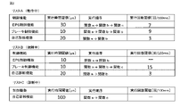
- list A120, list B121, list C122 The configuration of a plurality of lists (list A120, list B121, list C122) held by the list management unit 113 according to the first embodiment will be described with reference to FIG.
- the control functions EPS control function 130, brake control function 131, self-diagnosis function 132
- control functions of the control unit 114 to be monitored are normal. The operation is described.
- control function In list A120, list B121, and list C122, "control function", "execution time threshold value”, and “execution order” in the normal case are predetermined as factors for determining that the operation state of the control function is normal. Items such as “threshold of the number of executions” in the period are set. These items are optional, and other items may be used as long as they can specify the operation of the program.
- the "execution time threshold” is the time from the start to the end of the execution of the function as the execution time, and in addition to the execution time, the processing delay caused by the interrupt of the high-priority function is taken into consideration. Set by the designer or learning algorithm. Further, even if the functions are the same, the threshold value of the execution time to be set changes depending on the state in which the vehicle is placed, when the processing is not executed or when the processing delay is not allowed. ..
- the threshold value of the execution time to be set changes depending on the state in which the vehicle is placed, when the processing is not executed or when the processing delay is not allowed. ..
- the automatic steering process is performed while the control function is in operation. However, in the state of failure, it is dangerous to leave the steering to the system, so the automatic steering process is stopped and the driver switches to the manual steering. In this case, the execution time changes depending on the presence or absence of the automatic steering process during the failure and the operation.
- the "execution order" is the order of the processes executed in the function, and may be, for example, the order of the functions to be executed or the order of the addresses of the instructions to be executed.
- the set execution order changes when the process includes the process to be executed only in a specific state or when the order of the processes executed changes according to the state. ..
- the self-diagnosis function in the operating state, the function related to vehicle control is prioritized over the self-diagnosis function. Therefore, a process with a large resource usage or a process with a large processing load is not executed in the operating state, but is executed only in the diagnostic state. In this case, the execution order changes during operation and diagnosis.
- the "threshold value of the number of executions" in a predetermined period sets the minimum number of times to be executed in a predetermined period in the control function that is periodically activated.
- the number of executions in a predetermined period may occur when the start timing is changed due to a change in the priority of the control function or when the start is not periodic depending on the state.
- the threshold of changes For example, in the self-diagnosis function, the minimum processing is executed by periodic activation in the operating or failure state, so by monitoring the number of executions in a predetermined period, the control function is activated correctly. Monitor whether or not.
- the number of executions in a predetermined period cannot be monitored.
- the monitoring unit 112 manages the list by associating the division unit of the list stored in the list management unit 113 with the state acquired by the state management unit 110. Reference is made to the list A120 from the unit 113, and only the control functions described in the list A120 and the operation of these control functions are monitored.
- the control unit 114 includes a plurality of control functions (EPS control function 130, brake control function 131, self-diagnosis function 132) for controlling the ADAS control device 100.
- EPS control function 130 brake control function 131
- self-diagnosis function 132 self-diagnosis function
- step S201 the state management unit 110 acquires a value indicating the state in which the ADAS control device 100 is placed.
- the timing of acquiring the value may be acquired at a predetermined cycle, or may be acquired each time the state changes.
- step S202 the state management unit 110 writes a value indicating the state acquired in step S201 to the storage unit 111.
- the storage unit 111 stores the written value until the state management unit 110 newly acquires and writes a value indicating the state.
- step S203 the monitoring unit 112 selects a list (list A120, list B121, list C122) to be referenced from the list management unit 113 based on the state stored in the storage unit 111. Specifically, in FIG. 2, when the storage unit 111 stores a value indicating an operating state, the monitoring unit 112 refers to the list A120.
- step S204 the monitoring unit 112 acquires information related to the operation of the running control function (EPS control function 130, brake control function 131, self-diagnosis function 132) and the control function from the control unit 114.
- EPS control function 130 EPS control function 130
- brake control function 131 brake control function 131
- self-diagnosis function 132 the control function from the control unit 114.
- step S205 the monitoring unit 112 compares the list selected in step S203 with the information related to the running control function acquired in step S204 and the operation of the controlling function, so that the running control function is normal or abnormal. Is determined. Specifically, first, it is compared whether the acquired control function during execution is described in the referenced list. When the control function being executed is listed in the list, the operation of the control function being executed is compared with the normal operation of the control function in the list, and if all the conditions are satisfied, it is normal, even one item. If the conditions are not met, it is judged to be abnormal.
- step S205 If it is determined in step S205 that the control function being executed is normal (no abnormality), the monitoring process is repeated. If it is determined in step S205 that the control function being executed is abnormal (abnormality exists), the monitoring process is terminated. After the monitoring process is completed, the list referred to in the monitoring process is used to perform the action after the abnormality detection, such as the status information of the ADAS control device 100 at the time of abnormality detection, the information of the control function determined to be abnormal, and the operation information. It may be passed to a function or a module.
- the vehicle-mounted control system As described above, according to the vehicle-mounted control system according to the first embodiment, it is possible to monitor the control function and operation of the vehicle-mounted control system according to the state of the ADAS control device 100. Further, since only the control function that needs to be monitored can be monitored according to the state of the ADAS control device 100, redundant monitoring can be suppressed.
- the normal operation of the control function can be determined for each state, so that the permissible range of the threshold value is suppressed from expanding and the control function can be controlled. Normal operation can be determined more strictly, and security resistance can be improved.
- the abnormality occurrence location and the abnormality spread location can be specified from the information on the state of the ADAS control device 100 at the time of abnormality detection, the information on the control function determined to be abnormal, and the operation information. In addition, by using the specified information, it is possible to connect to the treatment and analysis after the abnormality is detected.
- Embodiment 2 Next, the ADAS control device according to the second embodiment will be described with reference to FIGS. 4 to 6.
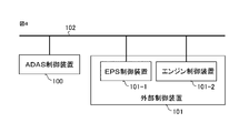
- FIG. 4 is a diagram showing an example of the configuration of the ADAS control device according to the second embodiment.
- the ADAS control device 100 is connected to the EPS control device 101-1 and the engine control device 101-2 of the external control device 101, respectively, through the vehicle-mounted network 102.
- the in-vehicle network 102 may be CAN (Control Area Network), Ethernet, or the like, but is not limited thereto.
- the configuration shown in FIG. 4 is an example, and any form may be used as long as the ADAS control device 100 and the external control device 101 are connected by a communication line capable of transmitting the information of the device.
- the ADAS control device 100 has the same configuration as shown in FIG.
- the ADAS control device 100 includes a state management unit 110, a storage unit 111, a monitoring unit 112, a list management unit 113, and a control unit 114.
- the state management unit 110 includes a list A120, a list B121, and a list C122
- the control unit 114 includes an EPS control function 130, a brake control function 131, and a self-diagnosis function 132.
- the configuration shown in FIGS. 1 and 4 is an example, and includes a state management unit 110, a storage unit 111, a monitoring unit 112, a list management unit 113, and a control unit 114, and includes one or more external control devices 101. As long as it is connected through the in-vehicle network 102, it does not necessarily have to be as shown in FIGS. 1 and 4.
- the second embodiment is different from the first embodiment in that the ADAS control device 100 is connected to the EPS control device 101-1 and the engine control device 101-2 of the external control device 101 through the vehicle-mounted network 102.
- the external control device 101 may be, for example, an ECU or a device having a sensing function.
- the state management unit 110 acquires sensor values or failure information of the EPS control device 101-1 and the engine control device 101-2 via the in-vehicle network 102, in addition to the value indicating the state of the ADAS control device 100. do.
- the sensor values are, for example, vehicle speed, steering angle, engine speed, and the like.
- the state management unit 110 determines a value corresponding to the current vehicle state based on the acquired value and information, and writes a value indicating the current vehicle state in the storage unit 111.
- the state of the vehicle is, for example, stopped, normal running, degenerate running, diagnosis, and the like.
- the storage unit 111 stores a value indicating the current state of the vehicle determined by the state management unit 110, and continuously maintains the storage until a new value is written. Further, when the state of the vehicle changes during a predetermined period and the state management unit 110 determines a new state different from the previous one, the value before the state change is not overwritten and is combined with the value before the state change. A value indicating a new state is stored as a state transition in a predetermined period.
- the predetermined period is set within a range in which the state of the vehicle determined by the state management unit 110 differs depending on the state transition in that period. For example, when the current state of the vehicle is determined to be stopped, the required control function and the required monitoring differ depending on whether the previous state is normal driving or degenerate driving. , Even if the vehicle is stopped at the same level, it is regarded as a different vehicle condition.
- the monitoring unit 112 selects a list (list A120, list B121, list C122) to be referenced from the list management unit 113 based on the state stored in the storage unit 111.
- the monitoring unit 112 may select the list based on the current state of the vehicle stored in the storage unit 111, or may select it based on the state transition in a predetermined period.
- the list management unit 113 stores a plurality of lists (list A120, list B121, list C122), and provides the list according to a request from the monitoring unit 112.
- the stored list is divided into the current vehicle state stored in the storage unit 111, the vehicle state based on the state transition in a predetermined period, or the list is divided into functional units, and the vehicle is divided. You may refer to multiple lists for each state.
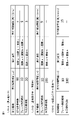
- list A120, list B121, list C122 The configuration of a plurality of lists (list A120, list B121, list C122) stored in the list management unit 113 according to the second embodiment will be described with reference to FIG.
- the list A120, the list B121, and the list C122 are functions of the control unit 114 (EPS control function 130) to be monitored in the state stored in the storage unit 111 or the state transition in a predetermined period.
- EPS control function 130 EPS control function 130
- Brake control function 131, self-diagnosis function 132 Brake control function 131, self-diagnosis function 132) and normal operation of the function are described.
- List A120, List B121, and List C122 in FIG. 5 are examples, and may not necessarily be as shown in FIG.
- the list management unit 113 refers to the list B121, and monitors only the functions described in the list B121 and the operations of these functions.
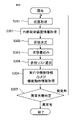
- step S201 the state management unit 110 acquires a value indicating the state of the ADAS control device 100.
- the timing of acquiring the value may be acquired at a predetermined cycle, or may be acquired each time the state changes.
- step S301 the EPS control device 101-1 and the engine control device 101-2 transmit their own sensor values or failure information to the ADAS control device 100 via the vehicle-mounted network 102, and the ADAS control device 100 Receives this.
- step S302 the state management unit 110 has a value indicating the state acquired in step S201 and communication data (sensor value, failure information, etc.) from the EPS control device 101-1 and the engine control device 101-2 received in step S301. Based on, the current state of the vehicle is determined.
- step S303 the state management unit 110 writes the current state of the vehicle determined in step S302 to the storage unit 111.
- the storage unit 111 stores the written value until the state management unit 110 newly acquires and writes a value indicating the state. Or, when acquiring and writing a new state during a predetermined period, the value before the state change is not overwritten, and the value indicating the new state is used as the state transition in the predetermined period together with the value before the state change.
- step S202 in FIG. 3 it stores not only the current state of the vehicle but also the state transition of the operating state in the past predetermined period.
- step S304 the monitoring unit 112 selects a list (list A120, list B121, list C122) to be referenced from the list management unit 113 based on the state stored in the storage unit 111. Specifically, in FIG. 5, a value indicating a stopped state is stored in the storage unit 111, and a value indicating a normal running state is stored as a state immediately before in a predetermined period. In this case, the monitoring unit 112 refers to the list B121. It differs from step S203 in FIG. 3 in that the list to be referred to is selected based not only on the current state of the vehicle but also on the state transition in the past predetermined period of the operating state.
- step S204 the monitoring unit 112 acquires information related to the operation of the running control function (EPS control function 130, brake control function 131, self-diagnosis function 132) and the control function from the control unit 114.
- EPS control function 130 EPS control function 130
- brake control function 131 brake control function 131
- self-diagnosis function 132 the control function from the control unit 114.
- step S205 the monitoring unit 112 compares the list selected in step S304 with the information related to the running control function acquired in step S204 and the operation of the controlling function, so that the running control function is normal or abnormal. Is determined. Specifically, first, it is compared whether the acquired control function during execution is described in the referenced list. When the control function being executed is listed in the list, the operation of the control function being executed is compared with the normal operation of the control function in the list. If it is not satisfied, it is judged as abnormal.
- step S205 If it is determined in step S205 that the control function being executed is normal (no abnormality), the monitoring process is repeated. If it is determined in step S205 that the control function being executed is abnormal (abnormality exists), the monitoring process is terminated. After the monitoring process is completed, using the list referenced in the monitoring process, information on the vehicle status, state transitions, control functions and operations determined to be abnormal at the time of abnormality detection, functions or modules that take measures after abnormality detection, etc. You may pass it to.
- the vehicle-mounted control device According to the vehicle-mounted control device according to the second embodiment, it is possible to monitor the control function and the operation of the control function of the vehicle-mounted control device according to the state of the vehicle. Further, since the state of the vehicle is determined in consideration of not only the current state of the vehicle but also the state transition of the operating state in the past predetermined period, the state of the vehicle can be determined in more detail.
- control function that needs to be monitored can be monitored according to the state of the vehicle, redundant monitoring can be suppressed.
- the normal operation of the control function can be determined for each state, so that the permissible range of the threshold value is suppressed and the normal operation of the control function is suppressed. Can be determined more strictly, and security resistance can be improved.
- the location where the abnormality occurs and the location where the abnormality spreads can be identified from the state of the vehicle at the time of abnormality detection, the state transition, and the control function and operation determined to be abnormal.
- the specified information it is possible to connect to the treatment and analysis after the abnormality is detected.
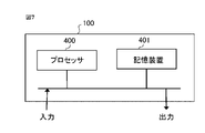
- the ADAS control device 100 is composed of a processor 400 and a storage device 401, as shown in FIG. 7 as an example of hardware.
- the storage device includes a volatile storage device such as a random access memory and a non-volatile auxiliary storage device such as a flash memory. Further, the auxiliary storage device of the hard disk may be provided instead of the flash memory.
- the processor 400 executes the program input from the storage device 401. In this case, a program is input from the auxiliary storage device to the processor 400 via the volatile storage device. Further, the processor 400 may output data such as a calculation result to the volatile storage device of the storage device 401, or may store the data in the auxiliary storage device via the volatile storage device.
- ADAS control device 101 external control device, 101-1 EPS control device, 101-2 engine control device, 102 in-vehicle network, 110 status management unit, 111 storage unit, 112 monitoring unit, 113 list management unit, 114 control unit, 120 list A, 121 list B, 122 list C, 130 EPS control function, 131 brake control function, 132 self-diagnosis function, 400 processor, 401 storage device
Landscapes
- Engineering & Computer Science (AREA)
- Theoretical Computer Science (AREA)
- Physics & Mathematics (AREA)
- General Physics & Mathematics (AREA)
- General Engineering & Computer Science (AREA)
- Quality & Reliability (AREA)
- Computing Systems (AREA)
- Automation & Control Theory (AREA)
- Mechanical Engineering (AREA)
- Mathematical Physics (AREA)
- Testing And Monitoring For Control Systems (AREA)
- Debugging And Monitoring (AREA)
- Steering Control In Accordance With Driving Conditions (AREA)
- Power Steering Mechanism (AREA)
Abstract
Description
有線または無線通信手段および通信網のネットワークが何らかの理由によって異常な状態に陥って、ECUの制御プログラムが異常な処理を行った場合には車両のユーザが意図しない不利益を被ることになる。
しかし、車載用の電子機器では、車両の状態の変化に対応してプログラムの実行状態が変化するため、複数の状態における様々な動作を予め登録し、実行中の動作と登録された全ての動作と比較を行うことによって動作の異常の有無の監視が行われていたため、監視が冗長となるという問題があった。
車載用制御システムとしてADAS(Advanced Driver Assistance System)制御装置を例として取り上げて説明する。
状態管理部110は、ADAS制御装置100の置かれている状態(運用状態)を数値によって表現して、状態に応じた数値を取得し、記憶部111に取得した値を書き込む。すなわち、ADAS制御装置100は、例えばECUであり、ADAS制御装置100の置かれている状態とは、例えば初期化中、動作中、故障中、診断中などの状態である。
したがって、状態管理部110は、車載用制御システム(ADAS制御装置100)の状態に基づいて運用状態を決定するということになる。
監視部112は、記憶部111に記憶されているADAS制御装置100の置かれている状態に基づいて、リスト管理部113から参照するリスト(リストA120、リストB121、リストC122)を選択する。また、監視部112は、ADAS制御装置100の制御部114において実行中の機能(EPS制御機能130、ブレーキ制御機能131、自己診断機能132)および機能の動作に関連する情報を取得し、参照しているリスト内の条件を満たす機能および動作が行われているかを比較する。比較対象とする主な要素は、例えば機能の実行時間、実行順序、予め定めた期間における実行回数である。
図2に示すように、リストA120、リストB121、リストC122には、監視対象となる制御部114の制御機能(EPS制御機能130、ブレーキ制御機能131、自己診断機能132)および制御機能の正常な動作が記載されている。
図3において、ステップS201において、状態管理部110は、ADAS制御装置100の置かれている状態を示す値を取得する。値を取得するタイミングは、予め定めた周期で取得してもよいし、あるいは状態が変化する都度取得してもよい。
ステップS205において、実行中の制御機能を異常と判定した場合(異常有)、監視処理を終了する。監視処理終了後、監視処理において参照したリストを用いて、異常検知時のADAS制御装置100の状態の情報、異常と判定された制御機能の情報および動作の情報を、異常検知後の処置を行う機能あるいはモジュールなどに渡してもよい。
さらに、ADAS制御装置100の状態に応じて、監視が必要な制御機能のみを監視することができるため、冗長な監視を抑えることができる。
次に、実施の形態2に係るADAS制御装置について、図4から図6までに基づいて説明する。
ADAS制御装置100は、状態管理部110、記憶部111、監視部112、リスト管理部113、制御部114を備えて構成されている。また、状態管理部110は、リストA120、リストB121、リストC122を備えており、制御部114は、EPS制御機能130、ブレーキ制御機能131、自己診断機能132を備えて構成されている。なお、図1および図4に示す構成は一例であり、状態管理部110と記憶部111と監視部112とリスト管理部113と制御部114を備えており、一つ以上の外部制御装置101と車載ネットワーク102を通して繋がっていれば、必ずしも図1および図4の通りでなくてもよい。
状態管理部110は、ADAS制御装置100の持つ状態を示す値に加えて、車載ネットワーク102を経由して、EPS制御装置101-1とエンジン制御装置101-2のセンサー値あるいは故障情報等を取得する。センサー値は、例えば車速、操舵角、エンジン回転数などである。
図5に示すように、リストA120、リストB121、リストC122は、記憶部111に記憶されている状態あるいは予め定めた期間における状態遷移において、監視対象となる制御部114の機能(EPS制御機能130、ブレーキ制御機能131、自己診断機能132)および機能の正常な動作が記載されている。図5のリストA120、リストB121、リストC122は一例であり、必ずしも図5の通りでなくてもよい。
図6において、ステップS201において、状態管理部110は、ADAS制御装置100の持つ状態を示す値を取得する。値を取得するタイミングは、予め定めた周期で取得してもよいし、あるいは状態が変化する都度取得してもよい。
ステップS302において、状態管理部110は、ステップS201において取得した状態を示す値とステップS301において受信したEPS制御装置101-1およびエンジン制御装置101-2からの通信データ(センサー値あるいは故障情報等)に基づいて、現在の車両の状態を決定する。
ステップS205において、実行中の制御機能を異常と判定した場合(異常有)、監視処理を終了する。監視処理終了後、監視処理において参照したリストを用いて、異常検知時の車両の状態、状態遷移、異常と判定された制御機能および動作の情報を、異常検知後の処置を行う機能あるいはモジュールなどに渡してもよい。
さらに、現在の車両の状態だけでなく、運用状態の過去の予め定めた期間における状態遷移を考慮して車両の状態を定めるため、より詳細に車両の状態を定めることができる。
さらに、車両の状態に応じて動作が変化する制御機能に対して、制御機能の正常な動作を状態ごとに定めることができるため、閾値の許容範囲が広がるのを抑え、制御機能の正常な動作をより厳密に定めることができ、セキュリティ耐性を向上させることができる。
Claims (10)
- システムの運用状態の情報を取得する状態管理部、前記状態管理部によって取得された前記システムの運用状態の情報を記憶する記憶部、複数の制御機能を有する制御部、前記制御部の制御機能と前記制御機能の正常な動作状態との対応関係が定められたリストを保有するリスト管理部、および前記記憶部に記憶された前記運用状態に基づいて前記リスト管理部に保有されている前記リストを選択し、前記リストに定められた制御機能の正常な動作状態と前記制御部の実行状態とを比較して前記制御機能の動作が正常か否かを監視する監視部を備えたことを特徴とする車載用制御システム。
- 前記リストには、前記制御機能の動作状態が正常であるとの判断要素に、前記制御機能の実行時間の閾値が設定されていることを特徴とする請求項1に記載の車載用制御システム。
- 前記リストには、前記制御機能の動作状態が正常であるとの判断要素に、正常な場合の前記制御機能の実行順序が含められていることを特徴とする請求項1または2に記載の車載用制御システム。
- 前記リストには、前記制御機能の動作状態が正常であるとの判断要素に、正常な場合の前記制御機能の予め定めた期間における実行回数の閾値が含められていることを特徴とする請求項1から3のいずれか1項に記載の車載用制御システム。
- 前記状態管理部は、前記システムの状態に基づいて前記運用状態を決定することを特徴とする請求項1から4のいずれか1項に記載の車載用制御システム。
- 前記状態管理部は、前記制御部とは異なる外部制御装置から通信データを取得し、前記通信データを用いて、前記運用状態を決定することを特徴とする請求項1から4のいずれか1項に記載の車載用制御システム。
- 前記記憶部は、前記状態管理部で取得された運用状態と前記運用状態の過去の予め定めた期間における状態遷移を記憶することを特徴とする請求項1から6いずれか1項に記載の車載用制御システム。
- 前記監視部は、前記運用状態の過去の予め定めた期間における状態遷移に基づいて前記リストを選択することを特徴とする請求項7に記載の車載用制御システム。
- 前記リスト管理部は、前記記憶部に記憶される運用状態ごとのリストを保有していることを特徴とする請求項1から8のいずれか1項に記載の車載用制御システム。
- 前記システムは車両に搭載され、前記状態管理部で取得される運用状態は車両の状態であることを特徴とする請求項1から9のいずれか1項に記載の車載用制御システム。
Priority Applications (5)
| Application Number | Priority Date | Filing Date | Title |
|---|---|---|---|
| CN202080107153.XA CN116438521A (zh) | 2020-11-24 | 2020-11-24 | 车载用控制系统 |
| US18/028,279 US12491829B2 (en) | 2020-11-24 | 2020-11-24 | In-vehicle use control system |
| DE112020007796.9T DE112020007796T5 (de) | 2020-11-24 | 2020-11-24 | In-fahrzeug-verwendung-steuersystem |
| PCT/JP2020/043581 WO2022113155A1 (ja) | 2020-11-24 | 2020-11-24 | 車載用制御システム |
| JP2022564710A JP7504222B2 (ja) | 2020-11-24 | 2020-11-24 | 車載用制御システム |
Applications Claiming Priority (1)
| Application Number | Priority Date | Filing Date | Title |
|---|---|---|---|
| PCT/JP2020/043581 WO2022113155A1 (ja) | 2020-11-24 | 2020-11-24 | 車載用制御システム |
Publications (1)
| Publication Number | Publication Date |
|---|---|
| WO2022113155A1 true WO2022113155A1 (ja) | 2022-06-02 |
Family
ID=81754080
Family Applications (1)
| Application Number | Title | Priority Date | Filing Date |
|---|---|---|---|
| PCT/JP2020/043581 Ceased WO2022113155A1 (ja) | 2020-11-24 | 2020-11-24 | 車載用制御システム |
Country Status (5)
| Country | Link |
|---|---|
| US (1) | US12491829B2 (ja) |
| JP (1) | JP7504222B2 (ja) |
| CN (1) | CN116438521A (ja) |
| DE (1) | DE112020007796T5 (ja) |
| WO (1) | WO2022113155A1 (ja) |
Families Citing this family (1)
| Publication number | Priority date | Publication date | Assignee | Title |
|---|---|---|---|---|
| CN119126757B (zh) * | 2024-09-09 | 2025-04-22 | 镁佳(武汉)科技有限公司 | 用于车辆远程控制的方法、装置、设备和存储介质 |
Citations (5)
| Publication number | Priority date | Publication date | Assignee | Title |
|---|---|---|---|---|
| JPH04268931A (ja) * | 1991-02-25 | 1992-09-24 | Mazda Motor Corp | 機器の制御方法および装置 |
| JP2007251722A (ja) * | 2006-03-17 | 2007-09-27 | Fujitsu Ten Ltd | 通信装置、車載システム、データ保存方法及びプログラム |
| JP2008254507A (ja) * | 2007-04-02 | 2008-10-23 | Toyota Motor Corp | 車両用情報記録システム |
| JP2012089073A (ja) * | 2010-10-22 | 2012-05-10 | Denso Corp | 電子制御装置、及び、これを用いた電動パワーステアリング装置 |
| WO2016047575A1 (ja) * | 2014-09-25 | 2016-03-31 | 日本精工株式会社 | 車載用電子機器の制御装置及び制御方法 |
Family Cites Families (9)
| Publication number | Priority date | Publication date | Assignee | Title |
|---|---|---|---|---|
| JPH0445885Y2 (ja) | 1986-07-09 | 1992-10-28 | ||
| KR100693891B1 (ko) * | 2004-07-10 | 2007-03-12 | 최낙봉 | 실시간 열차고장 관리시스템 |
| JP5230557B2 (ja) * | 2009-08-03 | 2013-07-10 | 日立オートモティブシステムズ株式会社 | 車両故障判定装置、車両故障判定装置設計プログラム |
| WO2016046931A1 (ja) | 2014-09-25 | 2016-03-31 | 日本精工株式会社 | 車載用電子機器の制御装置及び制御方法 |
| JP6164374B2 (ja) | 2014-09-25 | 2017-07-26 | 日本精工株式会社 | 車載用電子機器の制御装置及び制御方法 |
| JP6223380B2 (ja) * | 2015-04-03 | 2017-11-01 | 三菱電機ビルテクノサービス株式会社 | 中継装置及びプログラム |
| JP2018018251A (ja) * | 2016-07-27 | 2018-02-01 | ファナック株式会社 | 数値制御装置 |
| US20190217869A1 (en) * | 2018-01-12 | 2019-07-18 | Panasonic Intellectual Property Management Co., Ltd. | Control apparatus, control method, and program |
| CN108803581B (zh) * | 2018-08-17 | 2021-01-12 | 广州瑞修得信息科技有限公司 | 一种基于专家模板的故障远程诊断方法 |
-
2020
- 2020-11-24 WO PCT/JP2020/043581 patent/WO2022113155A1/ja not_active Ceased
- 2020-11-24 US US18/028,279 patent/US12491829B2/en active Active
- 2020-11-24 CN CN202080107153.XA patent/CN116438521A/zh active Pending
- 2020-11-24 DE DE112020007796.9T patent/DE112020007796T5/de active Pending
- 2020-11-24 JP JP2022564710A patent/JP7504222B2/ja active Active
Patent Citations (5)
| Publication number | Priority date | Publication date | Assignee | Title |
|---|---|---|---|---|
| JPH04268931A (ja) * | 1991-02-25 | 1992-09-24 | Mazda Motor Corp | 機器の制御方法および装置 |
| JP2007251722A (ja) * | 2006-03-17 | 2007-09-27 | Fujitsu Ten Ltd | 通信装置、車載システム、データ保存方法及びプログラム |
| JP2008254507A (ja) * | 2007-04-02 | 2008-10-23 | Toyota Motor Corp | 車両用情報記録システム |
| JP2012089073A (ja) * | 2010-10-22 | 2012-05-10 | Denso Corp | 電子制御装置、及び、これを用いた電動パワーステアリング装置 |
| WO2016047575A1 (ja) * | 2014-09-25 | 2016-03-31 | 日本精工株式会社 | 車載用電子機器の制御装置及び制御方法 |
Also Published As
| Publication number | Publication date |
|---|---|
| JP7504222B2 (ja) | 2024-06-21 |
| US20230398955A1 (en) | 2023-12-14 |
| CN116438521A (zh) | 2023-07-14 |
| US12491829B2 (en) | 2025-12-09 |
| DE112020007796T5 (de) | 2023-09-28 |
| JPWO2022113155A1 (ja) | 2022-06-02 |
Similar Documents
| Publication | Publication Date | Title |
|---|---|---|
| JP6714611B2 (ja) | 車両の電子制御システムに冗長性を付与する方法及び装置 | |
| CN102741818B (zh) | 故障诊断系统、用于车辆的电子控制单元、故障诊断方法 | |
| JP6147356B2 (ja) | 監視装置、制御システム及び監視プログラム | |
| JP2010285001A (ja) | 電子制御システム、機能代行方法 | |
| JP6140448B2 (ja) | 制御装置内の監視構想 | |
| CN106965805A (zh) | 基于风险的车辆控制 | |
| WO2015045507A1 (ja) | 車両用制御装置 | |
| WO2022113155A1 (ja) | 車載用制御システム | |
| US10296322B2 (en) | Controller and control program updating method | |
| JP5582748B2 (ja) | 車両用電子制御装置 | |
| CN109709849B (zh) | 单片机安全运行控制方法与装置 | |
| JP6345447B2 (ja) | 自動車用電子制御装置 | |
| JP2018134964A (ja) | 自動車用電子制御装置 | |
| Suwatthikul | Fault detection and diagnosis for in-vehicle networks | |
| JP6349444B2 (ja) | 車両用制御装置 | |
| KR20160097593A (ko) | 차량 제어 장치 및 차량 제어 방법 | |
| JP6522550B2 (ja) | 電子制御装置 | |
| CN111149088A (zh) | 用于运行控制器的方法以及具有对应的控制器的设备 | |
| JPH0717337A (ja) | 電子制御ユニットの故障判定方法及び故障判定装置 | |
| JP7070206B2 (ja) | 車載制御装置 | |
| JP6533489B2 (ja) | 車載用制御装置 | |
| JP2011126327A (ja) | 車載制御装置 | |
| JP2007283788A (ja) | 車両用電子制御装置 | |
| JP6887277B2 (ja) | 自動車用電子制御装置 | |
| JP7803720B2 (ja) | 制御装置及び電子制御装置 |
Legal Events
| Date | Code | Title | Description |
|---|---|---|---|
| 121 | Ep: the epo has been informed by wipo that ep was designated in this application |
Ref document number: 20963420 Country of ref document: EP Kind code of ref document: A1 |
|
| ENP | Entry into the national phase |
Ref document number: 2022564710 Country of ref document: JP Kind code of ref document: A |
|
| WWE | Wipo information: entry into national phase |
Ref document number: 112020007796 Country of ref document: DE |
|
| 122 | Ep: pct application non-entry in european phase |
Ref document number: 20963420 Country of ref document: EP Kind code of ref document: A1 |