WO2022107553A1 - 基板保持装置 - Google Patents
基板保持装置 Download PDFInfo
- Publication number
- WO2022107553A1 WO2022107553A1 PCT/JP2021/039279 JP2021039279W WO2022107553A1 WO 2022107553 A1 WO2022107553 A1 WO 2022107553A1 JP 2021039279 W JP2021039279 W JP 2021039279W WO 2022107553 A1 WO2022107553 A1 WO 2022107553A1
- Authority
- WO
- WIPO (PCT)
- Prior art keywords
- polishing
- polishing head
- power generation
- generation device
- substrate holding
- Prior art date
- Legal status (The legal status is an assumption and is not a legal conclusion. Google has not performed a legal analysis and makes no representation as to the accuracy of the status listed.)
- Ceased
Links
Images




Classifications
-
- B—PERFORMING OPERATIONS; TRANSPORTING
- B24—GRINDING; POLISHING
- B24B—MACHINES, DEVICES, OR PROCESSES FOR GRINDING OR POLISHING; DRESSING OR CONDITIONING OF ABRADING SURFACES; FEEDING OF GRINDING, POLISHING, OR LAPPING AGENTS
- B24B37/00—Lapping machines or devices; Accessories
- B24B37/27—Work carriers
- B24B37/30—Work carriers for single side lapping of plane surfaces
-
- B—PERFORMING OPERATIONS; TRANSPORTING
- B24—GRINDING; POLISHING
- B24B—MACHINES, DEVICES, OR PROCESSES FOR GRINDING OR POLISHING; DRESSING OR CONDITIONING OF ABRADING SURFACES; FEEDING OF GRINDING, POLISHING, OR LAPPING AGENTS
- B24B49/00—Measuring or gauging equipment for controlling the feed movement of the grinding tool or work; Arrangements of indicating or measuring equipment, e.g. for indicating the start of the grinding operation
- B24B49/08—Measuring or gauging equipment for controlling the feed movement of the grinding tool or work; Arrangements of indicating or measuring equipment, e.g. for indicating the start of the grinding operation involving liquid or pneumatic means
-
- B—PERFORMING OPERATIONS; TRANSPORTING
- B24—GRINDING; POLISHING
- B24B—MACHINES, DEVICES, OR PROCESSES FOR GRINDING OR POLISHING; DRESSING OR CONDITIONING OF ABRADING SURFACES; FEEDING OF GRINDING, POLISHING, OR LAPPING AGENTS
- B24B49/00—Measuring or gauging equipment for controlling the feed movement of the grinding tool or work; Arrangements of indicating or measuring equipment, e.g. for indicating the start of the grinding operation
- B24B49/10—Measuring or gauging equipment for controlling the feed movement of the grinding tool or work; Arrangements of indicating or measuring equipment, e.g. for indicating the start of the grinding operation involving electrical means
-
- B—PERFORMING OPERATIONS; TRANSPORTING
- B24—GRINDING; POLISHING
- B24B—MACHINES, DEVICES, OR PROCESSES FOR GRINDING OR POLISHING; DRESSING OR CONDITIONING OF ABRADING SURFACES; FEEDING OF GRINDING, POLISHING, OR LAPPING AGENTS
- B24B49/00—Measuring or gauging equipment for controlling the feed movement of the grinding tool or work; Arrangements of indicating or measuring equipment, e.g. for indicating the start of the grinding operation
- B24B49/14—Measuring or gauging equipment for controlling the feed movement of the grinding tool or work; Arrangements of indicating or measuring equipment, e.g. for indicating the start of the grinding operation taking regard of the temperature during grinding
-
- H—ELECTRICITY
- H10—SEMICONDUCTOR DEVICES; ELECTRIC SOLID-STATE DEVICES NOT OTHERWISE PROVIDED FOR
- H10P—GENERIC PROCESSES OR APPARATUS FOR THE MANUFACTURE OR TREATMENT OF DEVICES COVERED BY CLASS H10
- H10P52/00—Grinding, lapping or polishing of wafers, substrates or parts of devices
Definitions
- the present invention relates to a substrate holding device for holding a substrate such as a wafer, and particularly to a substrate holding device used for a polishing device.
- This type of polishing device includes a polishing table that supports a polishing pad having a polishing surface, a substrate holding device that includes at least a polishing head for holding a wafer, and a polishing liquid supply nozzle that supplies the polishing liquid to the polishing surface. ing.
- the polishing device polishes the wafer as follows. While rotating the polishing table together with the polishing pad, the polishing liquid is supplied to the polishing surface from the polishing liquid supply nozzle. The wafer is held by the substrate holding device, and the wafer is further rotated about its axis. In this state, the polishing head rotates to press the surface of the wafer against the polishing surface of the polishing pad, and the surface of the wafer is brought into sliding contact with the polishing surface in the presence of the polishing liquid. The surface of the wafer is polished by the mechanical action of the abrasive grains contained in the polishing liquid and the chemical action of the polishing liquid. Such a polishing device is also called a CMP (chemical mechanical polishing) device.
- CMP chemical mechanical polishing
- the polishing state changes depending on the state of the pad (individual difference, usage history, dressing state), the state of the polishing liquid (slurry) (individual difference, concentration, temperature), and the state of the wafer film to be polished. Finely controlling the polishing conditions with respect to changes in the polishing state is indispensable for improving the polishing performance, but it is necessary to accurately grasp the polishing state in order to make a judgment.
- a sensor that indirectly measures the polishing state may be provided so as to rotate integrally with the polishing head, such as by fixing it to the polishing head.
- a component that requires electric power such as a sensor that indirectly measures the polishing state
- the above component is equipped with a secondary battery (battery) or is powered via a rotary connector. Needed to be supplied.
- the polishing head is provided with a retainer ring arranged so as to surround the wafer and an elastic film having a pressing surface for pressing the wafer, and the retainer ring and the elastic film need to be replaced regularly.
- a retainer ring arranged so as to surround the wafer and an elastic film having a pressing surface for pressing the wafer, and the retainer ring and the elastic film need to be replaced regularly.
- the polishing head is required to rotate and mechanically move up and down, and to be waterproof and chemical resistant to a polishing liquid (slurry), a cleaning liquid, and pure water. Therefore, it is difficult to supply electric power to a component that rotates integrally with the polishing head via the rotary connector.
- the elastic membrane forms many pressure areas (pressure chambers) to improve controllability.
- a large number of rotary joint systems for example, 12
- the present invention has been made in view of the above-mentioned conventional problems, and an object of the present invention is to provide a substrate holding device capable of easily supplying electric power to a component that rotates integrally with a polishing head.
- a substrate holding device used for a polishing device for polishing a substrate, and is a polishing head that presses the substrate against a polishing surface, a polishing head shaft connected to the head, the polishing head, and the polishing head.
- a substrate holding device comprising a power generation device that generates electric power in a rotating system including at least a shaft is provided.
- the substrate holding device further comprises a gas transfer line extending inside the polishing head, the power generation device is connected to the gas transfer line, and the power generation device flows through the gas transfer line. It is a wind power generation device that uses compressed gas to generate electric power.
- the power generation device is a stator that is arranged outside the rotation system side coil and forms a magnetic field between the rotation system side coil forming a part of the rotation system side coil and the rotation system side coil.
- the power generation device is a power generation device that generates power by utilizing the magnetic field formed by the stator and the electromagnetic induction generated by the rotation of the rotation system side coil.
- the substrate holding device further comprises a capacitor that stores the power generated by the power generation device.
- the storage is either a nickel metal hydride secondary battery, a lithium ion secondary battery, or a capacitor.
- the substrate holding device further includes a polishing state measuring sensor that constitutes a part of the rotating system, and the power generation device is configured to supply electric power to the polishing state measuring sensor.
- the polishing state measuring sensor is a temperature sensor that measures the temperature of the polishing head and / or the ambient temperature of the polishing head, a sound sensor that measures the sound pressure during polishing, and a vibration sensor that measures the vibration of the polishing head.
- a pressure sensor that measures the pressure of the compressed gas supplied to the pressure chamber formed in the polishing head, a flow sensor that measures the flow rate of the compressed gas, or a strain sensor that measures the strain of the polishing head.
- the substrate holding device further comprises an on-off valve that opens and closes a flow path of compressed gas supplied to a pressure chamber formed in the polishing head, and the power generation device supplies electric power to the on-off valve.
- the on-off valve constitutes a part of the rotary system.
- the substrate holding device further includes a wireless unit that transmits a measured value of a physical quantity measured by the polishing state measurement sensor to an operation control unit of the polishing device, and the wireless unit is one of the rotation systems. It constitutes a part.
- the power generation device generates electric power in the rotating system to supply electric power to the parts that rotate integrally with the polishing head. Therefore, electric power can be easily supplied to the component that rotates integrally with the polishing head.
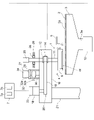
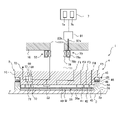
- FIG. 1 is a schematic view showing an embodiment of a polishing device provided with a substrate holding device according to an embodiment of the present invention.
- the polishing apparatus includes a substrate holding device 1 that holds and rotates a wafer W, which is an example of a substrate, a polishing table 3 that supports the polishing pad 2, and a polishing liquid (slurry) on the polishing pad 2.
- the polishing liquid supply nozzle 5 for supplying the polishing liquid and the operation control unit 7 for controlling the operation of each component of the polishing device are provided.
- a polishing pad 2 is attached to the upper surface of the polishing table 3, and the upper surface of the polishing pad 2 constitutes a polishing surface 2a for polishing the wafer W.
- the polishing pad 2 is configured to rotate integrally with the polishing table 3.
- the substrate holding device 1 includes a polishing head 9 that presses the wafer W against the polishing surface 2a, and a polishing head shaft 11 connected to the polishing head 9.
- the polishing head 9 is configured to hold the wafer W on the lower surface thereof by vacuum suction.
- the polishing table 3 is connected to a table rotation motor 13 arranged below the table shaft 3a via a table shaft 3a, and is rotatable around the table shaft 3a.
- the table rotation motor 13 constitutes a polishing surface moving mechanism that moves the polishing surface 2a in the horizontal direction.
- the polishing head shaft 11 moves up and down with respect to the polishing head swing arm 16 by the vertical movement mechanism 27. By moving the polishing head shaft 11 up and down, the entire polishing head 9 is moved up and down with respect to the polishing head swing arm 16 for positioning.
- a rotary joint 25 is attached to the upper end of the polishing head shaft 11.
- the vertical movement mechanism 27 that moves the polishing head shaft 11 and the polishing head 9 up and down includes a bridge 28 that rotatably supports the polishing head shaft 11 via a bearing 26, a ball screw 32 attached to the bridge 28, and a support column 30.
- a support base 29 supported by the support base 29 and a servomotor 34 provided on the support base 29 are provided.
- the support base 29 that supports the servomotor 34 is fixed to the polishing head swing arm 16 via the support column 30.
- the ball screw 32 includes a screw shaft 32a connected to the servomotor 34 and a nut 32b into which the screw shaft 32a is screwed.
- the polishing head shaft 11 moves up and down integrally with the bridge 28. Therefore, when the servomotor 34 is driven, the bridge 28 moves up and down via the ball screw 32, whereby the polishing head shaft 11 and the polishing head 9 move up and down.
- the polishing head shaft 11 is connected to the rotary cylinder 12 via a key (not shown).
- the rotary cylinder 12 is provided with a timing pulley 14 on the outer peripheral portion thereof.
- a polishing head motor 18 is fixed to the polishing head swing arm 16, and the timing pulley 14 is connected to a timing pulley 20 provided in the polishing head motor 18 via a timing belt 19. Therefore, by rotationally driving the polishing head motor 18, the rotary cylinder 12 and the polishing head shaft 11 rotate integrally via the timing pulley 20, the timing belt 19, and the timing pulley 14, and the polishing head 9 rotates its axis. Rotate as the center.
- the polishing head motor 18, the timing pulley 20, the timing belt 19, and the timing pulley 14 constitute a rotation mechanism for rotating the polishing head 9 about its axis.
- the polishing head swing arm 16 is supported by a support shaft 21 rotatably supported by a frame (not shown).
- the substrate holding device 1 can hold a substrate such as a wafer W on the lower surface of the polishing head 9.
- the polishing head swing arm 16 is configured to be rotatable around a support shaft 21.
- the polishing head motor 18 is connected to a rotation speed detector 23 that detects the rotation speed (rotation speed) of the polishing head motor 18, that is, the rotation speed of the polishing head 9.
- a rotation speed detector 23 is a rotary encoder.
- the polishing liquid supply nozzle 5, the table rotation motor 13, the vertical movement mechanism 27, the rotation speed detector 23, and the polishing head motor 18 are electrically connected to the operation control unit 7.
- the operation of the polishing liquid supply nozzle 5, the table rotation motor 13, the vertical movement mechanism 27, the rotation speed detector 23, and the polishing head motor 18 is controlled by the operation control unit 7.
- the operation control unit 7 includes a storage device 7a in which the program is stored and a processing device 7b that executes an operation according to an instruction included in the program.
- the processing device 7b includes a CPU (central processing unit) or a GPU (graphic processing unit) that performs operations according to instructions included in a program stored in the storage device 7a.
- the storage device 7a includes a main storage device (eg, a random access memory) accessible to the processing device 7b, and an auxiliary storage device (eg, a hard disk drive or a solid state drive) for storing data and programs.
- the motion control unit 7 is composed of at least one computer.
- Wafer W is polished as follows.
- the polishing head 9 and the polishing table 3 are rotated, respectively, and the polishing liquid is supplied onto the polishing pad 2 from the polishing liquid supply nozzle 5 provided above the polishing table 3.
- the polishing head 9 holding the wafer W on the lower surface is moved above the polishing table 3 from the receiving position of the wafer W by turning the polishing head swing arm 16.
- the polishing head 9 is lowered to press the wafer W against the polishing surface 2a of the polishing pad 2.
- the wafer W is slidably contacted with the polishing surface 2a in the presence of the polishing liquid, and the surface of the wafer W is polished by the mechanical action of the abrasive grains contained in the polishing liquid and the chemical action of the polishing liquid.
- the polishing head 9 and the polishing table 3 rotate in the same direction.
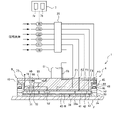
- FIG. 2 is a schematic view of the substrate holding device 1.
- the polishing head 9 is shown as a cross-sectional view.
- the polishing head 9 has an elastic film (membrane) 38 for pressing the wafer W against the polishing surface 2a of the polishing pad 2, a polishing head main body 10 for holding the elastic film 38, an annular drive ring 50, and an annular shape. It is equipped with a retainer ring 36.
- the elastic film 38 is attached to the lower part of the polishing head main body 10, and the lower surface of the elastic film 38 constitutes a pressing surface 38a that presses the wafer W against the polishing surface 2a.
- the polishing head body 10 is fixed to the end of the polishing head shaft 11, and the polishing head body 10, the elastic film 38, the drive ring 50, and the retainer ring 36 are integrally rotated by the rotation of the polishing head shaft 11. It is configured in.
- the retainer ring 36 and the drive ring 50 are configured to be movable up and down relative to the polishing head main body 10.
- the polishing head body 10 is made of a resin such as engineering plastic (for example, PEEK).
- pressure chambers 40, 41, 42, 43 are provided between the elastic film 38 and the polishing head main body 10.
- the pressure chambers 40, 41, 42, 43 are formed by the elastic film 38 and the polishing head main body 10.
- the central pressure chamber 40 is circular, and the other pressure chambers 41, 42, 43 are annular. These pressure chambers 40, 41, 42, 43 are concentrically arranged.
- Gas transfer lines F1, F2, F3 and F4 are connected to the pressure chambers 40, 41, 42 and 43, respectively.
- One end of the gas transfer lines F1, F2, F3, F4 is connected to a compressed gas supply source (not shown) as a utility provided in the factory where the polishing device is installed.
- a flow path for compressed gas is formed inside the gas transfer lines F1, F2, F3, and F4.
- a part of the gas transfer lines F1, F2, F3, F4 extends inside the polishing head 9 (specifically, the inside of the polishing head main body 10), and the compressed gas such as compressed air is the gas transfer line F1, It is supplied to the pressure chambers 40, 41, 42, 43 through F2, F3, and F4.
- the gas transfer line F3 communicating with the pressure chamber 42 is connected to a vacuum line (not shown), and it is possible to form a vacuum in the pressure chamber 42.
- An opening is formed in the portion of the elastic film 38 constituting the pressure chamber 42, and the wafer W is adsorbed and held by the polishing head 9 by forming a vacuum in the pressure chamber 42. Further, by supplying the compressed gas to the pressure chamber 42, the wafer W is released from the polishing head 9.
- the elastic film 38 is made of a rubber material having excellent strength and durability, such as ethylene propylene rubber (EPDM), polyurethane rubber, and silicone rubber.
- the retainer ring 36 is an annular member arranged around the elastic film 38 and in contact with the polishing surface 2a of the polishing pad 2.
- the retainer ring 36 is arranged so as to surround the pressing surface 38a and the outer peripheral edge of the wafer W, and prevents the wafer W from popping out from the polishing head 9 during polishing of the wafer W.
- the drive ring 50 is fixed to the upper surface of the retainer ring 36, and the upper portion of the drive ring 50 is connected to the annular retainer ring pressing mechanism 45.
- the retainer ring pressing mechanism 45 applies a downward load to the entire upper surface of the retainer ring 36 via the drive ring 50, thereby pressing the lower surface of the retainer ring 36 against the polishing surface 2a of the polishing pad 2.
- the retainer ring pressing mechanism 45 includes an annular piston 46 fixed to the upper part of the drive ring 50 and an annular rolling diaphragm 48 connected to the upper surface of the piston 46.
- a pressure chamber (retainering pressure chamber) 49 is formed inside the rolling diaphragm 48.
- the pressure chamber 49 is connected to the compressed gas supply source via a gas transfer line F5. The compressed gas is supplied into the pressure chamber 49 through the gas transfer line F5.
- the rolling diaphragm 48 pushes down the piston 46, the piston 46 pushes down the drive ring 50, and the drive ring 50 pushes down the entire retainer ring 36 downward. ..
- the retainer ring pressing mechanism 45 presses the lower surface of the retainer ring 36 against the polishing surface 2a of the polishing pad 2.
- the gas transfer lines F1, F2, F3, F4, F5 extend via the rotary joint 25 attached to the polishing head shaft 11.
- Pressure regulators R1, R2, R3, R4 and R5 are provided in the gas transfer lines F1, F2, F3, F4 and F5 communicating with the pressure chambers 40, 41, 42, 43 and 49, respectively.
- the compressed gas from the compressed gas supply source is independently supplied into the pressure chambers 40 to 43 and the pressure chamber 49 through the pressure regulators R1 to R5.
- the pressure regulators R1 to R5 are configured to regulate the pressure of the compressed gas in the pressure chambers 40 to 43 and the pressure chamber 49.
- the pressure regulators R1 to R5 are electrically connected to the operation control unit 7, and the operation of the pressure regulators R1 to R5 is controlled by the operation control unit 7.
- the pressure regulators R1 to R5 can change the internal pressures of the pressure chambers 40 to 43 and the pressure chamber 49 independently of each other, whereby the corresponding four regions of the wafer W, that is, the central portion, can be changed.
- the polishing pressure on the inner middle portion, the outer middle portion, and the edge portion, and the pressing pressure on the polishing pad 2 of the retainer ring 36 can be independently adjusted.
- the gas transfer lines F1, F2, F3, F4, and F5 are also connected to an air release valve (not shown), and the pressure chambers 40 to 43 and the pressure chamber 49 can be opened to the atmosphere.
- the elastic membrane 38 forms four pressure chambers 40 to 43, but in one embodiment, the elastic membrane 38 may form less than four pressure chambers or more than four pressure chambers. good.
- the substrate holding device 1 is measured by a power generation device 55 that generates electric power, a polishing state measurement sensor 52 that indirectly measures a physical quantity that indirectly represents the polishing state of the wafer W, and a polishing state measurement sensor 52.
- a wireless unit 68 for transmitting the measured value of the physical quantity is further provided.
- the power generation device 55 is configured to generate electric power in the rotation system 4 including the polishing head 9 and the polishing head shaft 11.
- the rotation system 4 is an assembly of components that are integrally formed with the polishing head 9 and the polishing head 9 so as to be rotatable around the axis of the polishing head 9.
- the rotation system 4 includes at least a polishing head 9 and a polishing head shaft 11.
- the power generation device 55, the polishing state measurement sensor 52, and the wireless unit 68 form a part of the rotation system 4.
- Examples of physical quantities that indirectly represent the polishing state of the wafer W are the temperature of the polishing head 9, the ambient temperature of the polishing head 9, the pressure and flow rate of the compressed gas, the sound pressure during polishing, the vibration of the polishing head 9, and the polishing head. 9 distortions and the like can be mentioned.
- Examples of the polishing state measuring sensor 52 include a temperature sensor, a pressure sensor, a flow rate sensor, a sound sensor, a vibration sensor, a strain sensor, and the like.
- the power generation device 55 is a device that converts kinetic energy into electric energy to generate electric power, and is a wind power generation device that generates electric power by using wind power.
- the substrate holding device 1 further includes a gas transfer line F6.
- One end of the gas transfer line F6 is connected to a compressed gas supply source (not shown) as a utility provided in a factory where a polishing device is installed, and the other end is open to the atmosphere.
- At least a part of the gas transfer line F6 extends inside the polishing head shaft 11 and inside the polishing head 9 (specifically, inside the polishing head main body 10), and the gas transfer line F6 extends to the polishing head shaft 11. It extends via the attached rotary joint 25. In other words, the gas transfer line F6 extends from the non-rotating system toward the rotating system 4 via the rotary joint 25.
- the power generation device 55 is connected to the gas transfer line F6, and the gas transfer line F6 is provided with a pressure regulator R6.
- a flow path of the compressed gas is formed inside the gas transfer line F6, and the compressed gas from the compressed gas supply source is discharged to the atmosphere through the pressure regulator R6 and the power generation device 55.
- the pressure regulator R6 is configured to regulate the pressure of the compressed gas in the gas transfer line F6.
- the pressure regulator R6 is electrically connected to the operation control unit 7, and the operation of the pressure regulator R6 is controlled by the operation control unit 7.
- the power generation device 55 is provided on the polishing head 9. Specifically, the power generation device 55 is arranged inside the polishing head main body 10.
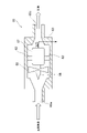
- FIG. 3 is a schematic diagram of the power generation device 55.
- the power generation device 55 includes a motor 57, a fan 60 that receives compressed gas, and a casing 63 that houses the motor 57 and the fan 60 inside.
- the fan 60 and the motor 57 are fixed to the inner surface of the casing 63 via a plurality of fixing members 62.
- the fan 60 is fixed to the rotating shaft 58 of the motor 57 and is arranged concentrically with the rotating shaft 58.
- An intake port 65a and an exhaust port 65b are formed in the casing 63, and the compressed gas from the compressed gas supply source flows into the inside of the casing 63 from the intake port 65a and is exhausted from the exhaust port 65b.
- the compressed gas exhausted from the exhaust port 65b is released into the atmosphere through the gas transfer line F6 (see FIG. 2).
- the rotating shaft 58 of the motor 57 extends in the flow direction of the compressed gas.
- the motor 57 generates electric power by rotating the rotating shaft 58. That is, the power generation device 55 is configured to generate electric power by using the compressed gas flowing through the gas transfer line F6.
- the compressed gas supplied to the power generation device 55 also cools the polishing head.
- the temperature of the polishing head 9 rises due to frictional heat during polishing and heat generated by a chemical reaction, and some parts of the polishing head 9 thermally expand and deform.
- the retainer ring 36 it is important to keep the temperature constant because the polishing rate of the outer peripheral portion of the wafer W changes depending on how it hits the polishing pad 2.
- the gas transfer line F6 needs to be cooled while in contact with parts requiring cooling (some of the parts requiring cooling are not shown) such as the retainer ring 36 in the polishing head main body 10. It is connected to the power generation device 55 while extending in the vicinity of various parts.
- the power generation device 55 may include a filter that allows the compressed gas to be exhausted to pass through. Particles generated by a brush (not shown) of the motor 57 may be mixed in the compressed gas that has passed through the power generation device 55, and when the compressed gas containing the particles is released into the atmosphere, the particles are polished. There is a risk of falling to 2. By exhausting the compressed gas through the filter, it is possible to prevent the particles from falling onto the polishing pad 2.
- the polishing state measuring sensor 52 is provided on the polishing head 9. Specifically, the polishing state measuring sensor 52 is arranged in the pressure chamber 40 and is fixed to the lower part of the polishing head main body 10.
- the polishing state measurement sensor 52 is a temperature sensor that measures the temperature of the polishing head 9 and / or the ambient temperature of the polishing head 9.
- the polishing state measuring sensor 52 may be a sound sensor that measures the sound pressure during polishing, or may be a vibration sensor that measures the vibration of the polishing head 9 generated during polishing. Examples of the sound sensor include an AE (Acoustic Emission) sensor and an acoustic sensor. An example of a vibration sensor is an accelerometer. Such sensors are available on the market.
- the position of the polishing state measuring sensor 52 is not limited to this embodiment as long as the polishing state measuring sensor 52 constitutes a part of the rotation system 4.
- the polishing state measurement sensor 52 may be fixed to the outer peripheral surface of the polishing head 9. During polishing of the wafer W, frictional heat due to friction between the wafer W and the polishing pad 2 and chemical reaction heat due to a chemical reaction between the wafer W and the polishing liquid (slurry) are generated, so that the polishing state measurement sensor 52 is heated.
- the polishing state measuring sensor 52 is arranged in the vicinity of the wafer W.
- the polishing state measuring sensor 52 is a pressure sensor that measures the pressure of the compressed gas supplied to any of the pressure chambers 40, 41, 42, 43, 49, as shown in FIG. It may be a flow sensor that measures the flow rate of the compressed gas supplied to any of the pressure chambers 40, 41, 42, 43, 49.
- the substrate holding device 1 includes a plurality of polishing state measuring sensors 52, and the plurality of polishing state measuring sensors 52 are connected to gas transfer lines F1, F2, F3, F4, F5, respectively. Specifically, each polishing state measurement sensor 52 is arranged on the downstream side of the rotary joint 25 with respect to the flow direction of the compressed gas.
- the plurality of polishing state measurement sensors 52 connected to the gas transfer lines F1, F2, F3, F4, F5 may be referred to as sensors S1, S2, S3, S4, S5, respectively.
- the substrate holding device 1 may include at least one of the sensors S1, S2, S3, S4, S5. Further, in one embodiment, the substrate holding device 1 may include both a polishing state measuring sensor 52 as a pressure sensor and a polishing state measuring sensor 52 as a flow rate sensor.
- the polishing state measuring sensor 52 may be a strain sensor that measures the strain of the polishing head 9 as shown in FIG.
- the polishing state measurement sensor 52 is attached to the outer periphery of the retainer ring 36. During polishing, the wafer W comes into contact with the downstream side of the retainer ring 36. As a result, the frictional force generated between the wafer W and the polishing pad 2 during polishing acts on the retainer ring 36, and the retainer ring 36 is distorted. In one example of this embodiment, the polishing state measuring sensor 52 measures the strain of the retainer ring 36.
- the polishing state measuring sensor 52 may measure the distortion of a part of the polishing head 9 due to the thermal expansion of a part of the polishing head 9 due to the temperature rise of the polishing head 9 during polishing.
- the polishing state measurement sensor 52 as a strain sensor is arranged in contact with a portion susceptible to the thermal expansion of the polishing head 9 or close to a portion susceptible to the thermal expansion of the polishing head 9.
- a strain sensor includes an element such as a piezoelectric element or a metal resistor capable of detecting the strain.
- the wireless unit 68 includes a wireless unit main body 69 and an antenna 73.
- the wireless unit 68 is provided on the polishing head 9.
- the wireless unit main body 69 is arranged inside the polishing head main body 10, but the position of the wireless unit 68 is in the present embodiment as long as the wireless unit 68 constitutes a part of the rotation system 4.
- the wireless unit 68 may be fixed to the outer peripheral surface of the polishing head 9.
- the power generation device 55 is connected to the polishing state measurement sensor 52 and the wireless unit 68, and the power generation device 55 supplies electric power to the polishing state measurement sensor 52 and the wireless unit 68. In other words, the electric power generated by the power generation device 55 is used to drive the polishing state measuring sensor 52 and the wireless unit 68.
- the polishing state measurement sensor 52 transmits the measured value of the physical quantity to the wireless unit 68.
- the wireless unit 68 has a function of transmitting and receiving a wireless signal, and transmits a measured value of a physical quantity output from the polishing state measurement sensor 52 to the operation control unit 7 by wireless communication with the operation control unit 7.
- the wireless unit main body 69 includes an AD converter 70 that converts an analog signal from the polishing state measurement sensor 52 into a digital signal, and a CPU (central processing) that compresses measurement data including measurement values of physical quantities output from the polishing state measurement sensor 52.
- the antenna 73 is connected to the transceiver 71, and the measured value of the physical quantity is transmitted to the operation control unit 7 via the antenna 73.
- the operation control unit 7 determines the polishing state and determines the polishing end point based on the measured value of the physical quantity measured by the polishing state measurement sensor 52. For example, the sound generated by the friction between the wafer W and the polishing pad 2 during polishing and the vibration of the polishing head 9 change depending on the polishing state (for example, the state of the polishing surface 2a and the state of the film of the wafer W). Therefore, in one embodiment, the motion control unit 7 may determine the polishing end point based on the change in sound pressure and the change in vibration measured by the polishing state measurement sensor 52.
- the motion control unit 7 compares the physical quantity (temperature, vibration, sound pressure, vibration, strain) measured by the polishing state measurement sensor 52 with a predetermined threshold value, and the physical quantity is predetermined. When it is larger than the specified threshold value, it may be determined that the polishing state is abnormal.
- the operation control unit 7 issues a command to the pressure regulators R1, R2, R3, R4, R5 based on the measured values of the pressures of the sensors S1, S2, S3, S4, S5, and the pressure chamber 40. , 41, 42, 43, 49 may be adjusted for the pressure of the compressed gas. Further, in one embodiment, the operation control unit 7 is connected to each of the gas transfer lines F1, F2, F3, F4, F5 based on the measured values of the flow rates of the sensors S1, S2, S3, S4, S5. A command may be issued to a control valve (not shown) to control the flow rate of the compressed gas supplied to the pressure chambers 40, 41, 42, 43, 49. As a result, the polishing head 9 can stably press the wafer W against the polishing surface 2a.
- the motion control unit 7 may determine the polishing end point based on the change in strain measured by the polishing state measurement sensor 52. Further, in one embodiment, the motion control unit 7 may determine the phase of the wafer W based on the periodic change of strain.
- the wireless unit 68 is also configured to receive a signal including a command from the operation control unit 7. As an example of such a command, there is a command to stop the operation of the polishing state measurement sensor 52. In one embodiment, if the polishing state measurement sensor 52 has a function of transmitting a measured value of a physical quantity, the wireless unit 68 may be omitted.
- FIG. 6 is a schematic diagram showing another embodiment of the substrate holding device 1. Since the configuration and operation of the present embodiment not particularly described are the same as those of the embodiments described with reference to FIGS. 1 to 3, the overlapping description thereof will be omitted.
- the substrate holding device 1 of the present embodiment further includes a capacitor 75 for storing the electric power generated by the power generation device 55.
- the capacitor 75 is connected to the power generation device 55, and the power generation device 55 generates electric power to charge the capacitor 75.
- the capacitor 75 is provided on the polishing head 9, and the capacitor 75 constitutes a part of the rotation system 4. Specifically, the capacitor 75 is arranged inside the polishing head main body 10, but the position of the capacitor 75 is not limited to this embodiment as long as the capacitor 75 constitutes a part of the rotation system 4.
- the capacitor 75 is connected to the polishing state measuring sensor 52 and the wireless unit 68, and is configured to be able to supply the electric power stored in the capacitor 75 to the polishing state measuring sensor 52 and the wireless unit 68. Therefore, it is possible to stably supply electric power to the polishing state measurement sensor 52 and the wireless unit 68 even when the power generation device 55 does not generate sufficient electric power as at the start of operation of the polishing apparatus.
- the storage device 75 include a nickel hydrogen secondary battery, a lithium ion secondary battery, and a capacitor. The configuration of this embodiment can also be applied to the embodiments described with reference to FIGS. 4 and 5.
- the power consumption of the wireless unit 68 is about 0.5 W, and the power consumption of the polishing state measurement sensor 52 is about 0.5 W. Therefore, assuming that the charging power to the storage battery 75 is 1 W, the total power generation capacity is 2 W. Is required.
- the substrate holding device 1 may include a voltmeter 76 for measuring the charge amount of the capacitor 75 (voltage of the capacitor 75).
- the voltmeter 76 is connected to the wireless unit 68, and the measured value of the voltage measured by the voltmeter 76 (the voltage of the capacitor 75, that is, the charge amount of the capacitor 75) is transmitted to the operation control unit 7.
- the operation control unit 7 may issue a command to the polishing state measuring sensor 52 based on the measured value of the voltage measured by the voltmeter 76 (the amount of charge of the capacitor 75). For example, the operation control unit 7 compares the charge amount of the capacitor 75 with a predetermined threshold value, and when the charge amount of the capacitor 75 is smaller than the predetermined threshold value, in order to suppress the power consumption. A command may be issued to the polishing state measuring sensor 52 to stop the operation of the polishing state measuring sensor 52.
- FIG. 8 is a schematic view showing still another embodiment of the substrate holding device 1. Since the configuration and operation of the present embodiment not particularly described are the same as those of the embodiments described with reference to FIGS. 1 and 2, the duplicate description thereof will be omitted.
- the substrate holding device 1 does not include the gas transfer line F6 and the pressure regulator R6.
- the power generation device 55 of the present embodiment is via a rotation system side coil 78 arranged on the rotation system 4 side, a stator 79 arranged outside the rotation system side coil 78, and power lines 82a and 82b. It has a power supply 81 connected to the stator 79.
- the power supply 81 is arranged inside the polishing head swing arm 16, but the position of the power supply 81 is not limited to this embodiment.
- the power supply 81 is electrically connected to the operation control unit 7, and the operation of the power supply 81 is controlled by the operation control unit 7.
- the rotation system side coil 78 is fixed to the polishing head shaft 11 and surrounds the polishing head shaft 11.
- the rotation system side coil 78 constitutes a part of the rotation system 4.
- the rotation system side coil 78 is an aggregate of a plurality of coils.
- the stator 79 is arranged so as to surround the rotation system side coil 78, and the rotation system side coil 78 and the stator 79 are separated from each other. Specifically, the stator 79 is fixed to the polishing head swing arm 16.
- the rotation system side coil 78 rotates integrally with the polishing head shaft 11, but the polishing head swing arm 16 does not rotate. That is, the stator 79 does not form a part of the rotation system 4, and the relative position of the stator 79 with respect to the polishing head swing arm 16 does not change.
- the stator 79 is configured to form a magnetic field between the stator 79 and the rotation system side coil 78.
- the stator 79 includes a stator core 79a and a stator-side coil 79b wound around the stator core 79a.
- the stator side coil 79b is an aggregate of a plurality of coils.
- the stator side coil 79b is connected to the power lines 82a and 82b, and the stator 79 and the rotation system side coil 78 are connected by passing a current from the power supply 81 to the stator side coil 79b via the power lines 82a and 82b. A magnetic field is formed between them.
- the stator 79 of the present embodiment is a so-called electromagnet.
- stator 79 As an electromagnet, a magnetic field is not generated when power is not supplied to the stator 79, so that it is possible to avoid the risk that the tool at the time of maintenance is attracted to the stator 79 by the magnetic force. ..
- the power generation device 55 of the present embodiment is a power generation device that generates electric power by utilizing the electromagnetic induction generated by the rotation of the magnetic field formed by the stator 79 and the rotation system side coil 78.
- the rotation system side coil 78 constitutes a part of the rotation system 4. Therefore, also in this embodiment, the power generation device 55 generates electric power in the rotation system 4.
- the stator 79 may be a permanent magnet. In this case, the board holding device 1 does not have to include the power supply 81.
- the substrate holding device 1 may include an electromagnetic shield 83 arranged below the rotation system side coil 78 and the stator 79.
- the electromagnetic shield 83 is arranged so as to surround the polishing head shaft 11 below the rotary system side coil 78 and the stator 79, and is configured to block electromagnetic waves downward from the rotary system side coil 78 and the stator 79. Has been done. Thereby, when the film pressure of the wafer W is measured by using the eddy current sensor, it is possible to prevent the adverse effect of the electromagnetic wave of the power generation device 55 on the eddy current sensor.
- the configuration of this embodiment can also be applied to the embodiment described with reference to FIG.
- the motion control unit 7 receives the measured value of the rotation speed of the polishing head motor 18 (that is, the rotation speed of the polishing head 9) from the rotation speed detector 23, and the rotation speed of the polishing head motor 18
- the current supplied from the power supply 81 to the stator side coil 79b may be controlled based on the above. For example, the operation control unit 7 compares the rotation speed with a predetermined lower limit threshold value, and when the rotation speed is smaller than the lower limit threshold value, issues a command to the power supply 81 and the stator side coil.
- the current supplied to 79b may be increased, and the operation control unit 7 compares the rotation speed with a predetermined upper limit threshold value, and when the rotation speed is larger than the upper limit threshold value, the power supply is supplied.
- a command may be issued to 81 to reduce the current supplied to the stator-side coil 79b.
- the operation control unit 7 is supplied from the power supply 81 to the stator side coil 79b based on the measured value of the voltage measured by the voltmeter 76 (see FIG. 7) (charge amount of the capacitor 75).
- the current may be controlled.
- the operation control unit 7 compares the charge amount of the capacitor 75 with a predetermined threshold value, and when the rotation speed is smaller than the threshold value, issues a command to the power supply 81 to the stator side.
- the current supplied to the coil 79b may be increased.
- FIG. 11 is a schematic diagram showing still another embodiment of the substrate holding device 1. Since the configuration and operation of the present embodiment not particularly described are the same as those of the embodiments described with reference to FIGS. 1 and 2, the duplicate description thereof will be omitted.
- the substrate holding device 1 does not include the gas transfer line F6 and the pressure regulator R6.
- the power generation device 55 is a power generation device that utilizes vibration energy. Specifically, the power generation device 55 of the present embodiment is a vibration power generation device that generates electric power in the rotation system 4 by utilizing the vibration during polishing.
- the power generation device 55 includes a piezoelectric element 85 that converts pressure due to vibration into electric power. Also in this embodiment, the power generation device 55 generates electric power in the rotation system 4.
- the power generation device 55 is provided on the polishing head 9. Specifically, the power generation device 55 is arranged inside the polishing head main body 10.
- the power generation device 55 of the present embodiment constitutes a part of the rotation system 4. As long as the power generation device 55 constitutes a part of the rotation system 4, the position of the power generation device 55 as the vibration power generation device is not limited to this embodiment. In one embodiment, the power generation device 55 may be fixed to the upper surface of the polishing head main body 10. The configuration of this embodiment can also be applied to the embodiments described with reference to FIGS. 4 to 7.
- FIG. 12 is a schematic view showing still another embodiment of the substrate holding device 1. Since the configuration and operation of the present embodiment not particularly described are the same as those of the embodiments described with reference to FIGS. 1 and 2, the duplicate description thereof will be omitted.
- the substrate holding device 1 does not include the gas transfer line F6 and the pressure regulator R6.
- the power generation device 55 is a power generation device that utilizes thermal energy. Specifically, the power generation device 55 of the present embodiment is during polishing such as frictional heat due to friction between the wafer W and the polishing pad 2 and chemical reaction heat due to a chemical reaction between the wafer W and the polishing liquid (slurry). It is a thermal power generation device that generates electric power in the rotary system 4 by using the generated heat.
- the power generation device 55 includes a Seebeck element 87 that converts thermal energy into electrical energy by the Seebeck effect. Also in this embodiment, the power generation device 55 generates electric power in the rotation system 4.
- the power generation device 55 is provided on the polishing head 9. Specifically, the power generation device 55 is arranged outside the polishing head 9. More specifically, the power generation device 55 is fixed to the upper surface of the polishing head main body 10. Due to the heat generated during polishing, the temperature of the polishing head 9 rises during polishing.
- the Zeebeck element 87 converts the temperature difference between the temperature of the polishing head 9 during polishing and the temperature of the atmosphere into a voltage. As a result, the power generation device 55 generates electric power.
- the power generation device 55 of this embodiment constitutes a part of the rotation system 4.
- the position of the power generation device 55 as a thermal power generation device is not limited to the present embodiment as long as it is arranged outside the polishing head 9 and in contact with the polishing head 9.
- the configuration of this embodiment can also be applied to the embodiments described with reference to FIGS. 4 to 7.
- FIG. 13 is a schematic view showing still another embodiment of the substrate holding device 1. Since the configuration and operation of the present embodiment not particularly described are the same as those of the embodiments described with reference to FIGS. 1 and 2, the duplicate description thereof will be omitted.
- the substrate holding device 1 does not include the gas transfer line F6 and the pressure regulator R6.
- the power generation device 55 is a power generation device (photovoltaic power generation device) using light energy.
- the power generation device 55 of the present embodiment includes a photoelectric conversion element 88 and a light source 89 that irradiates the photoelectric conversion element 88 with light.
- the photoelectric conversion element 88 By irradiating the photoelectric conversion element 88 with light from the light source 89, the photoelectric conversion element 88 converts the light energy from the light source 89 into electrical energy. As a result, the power generation device 55 generates electric power.
- An example of the photoelectric conversion element 88 is a solar cell.
- the power generation device 55 generates electric power in the rotation system 4.
- the photoelectric conversion element 88 is provided on the polishing head 9. Specifically, the power generation device 55 is arranged outside the polishing head 9. More specifically, the power generation device 55 is fixed to the upper surface of the polishing head main body 10.
- the photoelectric conversion element 88 constitutes a part of the rotation system 4.
- the light source 89 is arranged outside the polishing head 9, and its position is fixed. Therefore, the light source 89 does not form a part of the rotation system 4.
- the light source 89 is configured to be able to irradiate the entire upper surface of the polishing head main body 10. Therefore, the photoelectric conversion element 88 can be irradiated with light regardless of the position of the photoelectric conversion element 88 being polished.
- the configuration of this embodiment can also be applied to the embodiments described with reference to FIGS. 4 to 7.
- FIG. 14 is a schematic view showing still another embodiment of the substrate holding device 1. Since the configuration and operation of the present embodiment not particularly described are the same as those of the embodiments described with reference to FIGS. 1 to 3, the overlapping description thereof will be omitted.
- the substrate holding device 1 further includes on-off valves V1, V2, V3, V4, V5 that open and close the flow path of the compressed gas formed inside the gas transfer lines F1, F2, F3, F4, F5. I have.
- the on-off valves V1, V2, V3, V4, V5 are electrically driven (requires electric power) valves, and an electromagnetic valve is an example of the on-off valves V1, V2, V3, V4, V5.
- the on-off valves V1, V2, V3, V4, V5 are attached to the gas transfer lines F1, F2, F3, F4, F5, respectively.
- the on-off valves V1, V2, V3, V4, V5 are arranged on the downstream side of the rotary joint 25 in the flow direction of the compressed gas. Therefore, the on-off valves V1, V2, V3, V4, V5 form a part of the rotation system 4.
- the on-off valves V1, V2, V3, V4, V5 are connected to the power generation device 55, and the power generation device 55 supplies electric power to the on-off valves V1, V2, V3, V4, V5. In other words, the electric power generated by the power generation device 55 is used for the operation of the on-off valves V1, V2, V3, V4, V5.
- the on-off valves V1, V2, V3, V4, V5 are connected to the wireless unit 68. In one embodiment, the operation of the on-off valves V1, V2, V3, V4, V5 is controlled by the operation control unit 7. The configuration of this embodiment can also be applied to the embodiments described with reference to FIGS. 4 to 13.
- FIG. 15 is a schematic view showing still another embodiment of the substrate holding device 1. Since the configuration and operation of the present embodiment not particularly described are the same as those of the embodiment described with reference to FIG. 7, the duplicated description thereof will be omitted.
- the substrate holding device 1 of the present embodiment further includes a rotation system side control unit 91 provided on the polishing head 9.
- the rotation system side control unit 91 is connected to the power generation device 55, and the electric power generated by the power generation device 55 is used for the operation of the rotation system side control unit 91.
- the rotation system side control unit 91 constitutes a part of the rotation system 4.
- the rotation system side control unit 91 is arranged inside the polishing head main body 10.
- the rotation system side control unit 91 constitutes a part of the rotation system 4.
- the position of the rotation system side control unit 91 is not limited to this embodiment.
- the rotation system side control unit 91 includes a storage device 91a in which the program is stored and a processing device 91b that executes an operation according to an instruction included in the program.
- the processing device 91b includes a CPU (central processing unit) or a GPU (graphic processing unit) that performs operations according to instructions included in a program stored in the storage device 91a.
- the storage device 91a includes a main storage device (for example, a random access memory) accessible to the processing device 91b and an auxiliary storage device (for example, a hard disk drive or a solid state drive) for storing data and programs.
- the rotation system side control unit 91 is composed of at least one computer.
- the rotation system side control unit 91 is connected to the voltmeter 76, and the voltmeter 76 transmits a measured voltage value (charge amount of the capacitor 75) to the rotation system side control unit 91.
- the rotation system side control unit 91 manages energy based on the charge amount of the capacitor 75.
- the rotation system side control unit 91 compares the charge amount of the capacitor 75 with a predetermined threshold value, and if the charge amount of the capacitor 75 is smaller than the predetermined threshold value, it consumes it.
- a command may be issued to the polishing state measuring sensor 52 to stop the operation of the polishing state measuring sensor 52.
- the configuration of this embodiment can also be applied to the embodiments described with reference to FIGS. 1 to 6 and 8 to 14.
- the rotation system side control unit 91 is connected to the wireless unit 68.
- the rotation system side control unit 91 may perform control related to power generation on the main body side by wireless communication with the main body side (a portion of the board holding device 1 excluding the rotation system 4).
- the rotation system side control unit 91 may determine the rotation speed of the polishing head motor 18 and transmit the determined rotation speed to the polishing head motor 18.
- the rotation system side control unit 91 may control the current supplied from the power supply 81 to the stator side coil 79b based on the charge amount of the capacitor 75.
- the operation control unit 7 compares the charge amount of the capacitor 75 with a predetermined threshold value, and when the rotation speed is smaller than the threshold value, issues a command to the power supply 81 (see FIG. 8).
- the current supplied to the stator side coil 79b may be increased.
- the rotation system side control unit 91 receives the measured value of the rotation speed of the polishing head motor 18 (that is, the rotation speed of the polishing head 9) from the rotation speed detector 23, and receives the measured value of the polishing head motor 18.
- the current supplied from the power supply 81 to the stator-side coil 79b may be controlled based on the rotation speed. For example, the rotation system side control unit 91 compares the rotation speed with a predetermined lower limit threshold value, and when the rotation speed is smaller than the lower limit threshold value, issues a command to the power supply 81 and a stator.
- the current supplied to the side coil 79b may be increased, and the rotation system side control unit 91 compares the rotation speed with a predetermined upper limit threshold value, and the rotation speed is larger than the upper limit threshold value. At this time, a command may be issued to the power supply 81 to reduce the current supplied to the stator side coil 79b.
- the power generation device 55 of each embodiment described with reference to FIGS. 1 to 15 constitutes a part of the rotation system 4.
- the power generation device 55 described with reference to FIGS. 1 to 15 supplies electric power to a component (polishing state measuring sensor 52, on-off valves V1 to V5, etc.) that rotates integrally with the polishing head 9 in the rotating system 4. generate. Therefore, it is possible to easily supply electric power to a component that rotates integrally with the polishing head 9 and requires electric power. Further, when power is supplied to the above parts via the rotary joint 25, it is possible to avoid risks such as poor contact of the rotary connector of the rotary joint 25, failure of the rotary connector, and electric leakage.
- the present invention can be used for a substrate holding device for holding a substrate such as a wafer, and particularly can be used for a substrate holding device used for a polishing device.
Landscapes
- Engineering & Computer Science (AREA)
- Mechanical Engineering (AREA)
- Finish Polishing, Edge Sharpening, And Grinding By Specific Grinding Devices (AREA)
- Mechanical Treatment Of Semiconductor (AREA)
- Constituent Portions Of Griding Lathes, Driving, Sensing And Control (AREA)
Abstract
本発明は、ウェハなどの基板を保持する基板保持装置に関し、特に研磨装置に使用される基板保持装置に関するものである。基板保持装置(1)は、基板(W)を研磨面に押し付ける研磨ヘッド(9)と、研磨ヘッド(9)に連結された研磨ヘッドシャフト(11)と、研磨ヘッド(9)および研磨ヘッドシャフト(11)を少なくとも含む回転系(4)内で電力を発生させる発電装置(55)と、を備えている。
Description
本発明は、ウェハなどの基板を保持する基板保持装置に関し、特に研磨装置に使用される基板保持装置に関する。
半導体デバイスの製造工程では、ウェハの表面を研磨するために研磨装置が広く使用されている。この種の研磨装置は、研磨面を有する研磨パッドを支える研磨テーブルと、ウェハを保持するための研磨ヘッドを少なくとも含む基板保持装置と、研磨液を研磨面に供給する研磨液供給ノズルとを備えている。
研磨装置は次のようにしてウェハを研磨する。研磨パッドとともに研磨テーブルを回転させながら、研磨液供給ノズルから研磨液を研磨面に供給する。基板保持装置によりウェハを保持し、さらにウェハをその軸心を中心として回転させる。この状態で、研磨ヘッドは回転しながらウェハの表面を研磨パッドの研磨面に押し付け、研磨液の存在下でウェハの表面を研磨面に摺接させる。ウェハの表面は、研磨液に含まれる砥粒の機械的作用と、研磨液の化学的作用により研磨される。このような研磨装置はCMP(化学機械研磨)装置とも呼ばれる。
研磨状態はパッドの状態(個体差、使用履歴、ドレッシング状態)、研磨液(スラリー)の状態(個体差、濃度、温度)、被研磨物であるウェハ膜の状態によって変化する。研磨状態の変化に対して研磨条件を細かく制御することが研磨性能の向上に不可欠であるが、その判断には研磨状態を精度よく把握することが必要である。研磨状態を精度よく把握するために、研磨状態を間接的に測定するセンサを、研磨ヘッドに固定するなど、研磨ヘッドと一体に回転するように設ける場合がある。
研磨状態を間接的に測定するセンサなどの電力を必要とする部品を研磨ヘッドと一体に回転するように設ける場合、上記部品は二次電池(バッテリー)を搭載するか、ロータリーコネクタを介して電力を供給される必要があった。
研磨ヘッドは、ウェハを囲むように配置されたリテーナリングやウェハを押圧する押圧面を有する弾性膜を備えており、リテーナリングや弾性膜は定期的に交換される必要がある。ロータリーコネクタを介して電力を必要とする部品に電力を供給する場合、リテーナリング等の交換時の電力線の脱着時のロータリーコネクタの接触不良や、ロータリーコネクタの故障や、ロータリーコネクタの故障による漏電が発生する可能性がある。また、研磨ヘッドは回転と上下の機械的な運動と、研磨液(スラリー)、洗浄液、純水に対する防水性、耐薬品性が求められている。そのため、ロータリーコネクタを介して研磨ヘッドと一体に回転する部品に電力を供給することは困難であった。
また、制御性向上のために弾性膜は、多くの加圧エリア(圧力室)を形成する。各エリアを個別に加圧するために、多くのロータリージョイントの系統数(例えば12個)が必要となり、電力を供給するロータリーコネクタを追加することが困難である。
本発明は、上述した従来の問題点に鑑みてなされたもので、研磨ヘッドと一体に回転する部品に容易に電力を供給することができる基板保持装置を提供することを目的とする。
一態様では、基板を研磨する研磨装置に使用される基板保持装置であって、前記基板を研磨面に押し付ける研磨ヘッドと、前記ヘッドに連結された研磨ヘッドシャフトと、前記研磨ヘッドおよび前記研磨ヘッドシャフトを少なくとも含む回転系内で電力を発生させる発電装置と、を備えている、基板保持装置が提供される。
一態様では、前記基板保持装置は、前記研磨ヘッドの内部を延びる気体移送ラインをさらに備え、前記発電装置は、前記気体移送ラインに接続されており、前記発電装置は、前記気体移送ラインを流れる圧縮気体を利用して電力を発生させる風力発電装置である。
一態様では、前記発電装置は、前記回転系の一部を構成する回転系側コイルと、前記回転側コイルの外側に配置され、かつ前記回転系側コイルとの間に磁界を形成する固定子を備え、前記発電装置は、前記固定子が形成する磁界と、前記回転系側コイルの回転とによって発生する電磁誘導を利用して電力を発生させる発電装置である。
一態様では、前記発電装置の少なくとも一部は、前記回転系の一部を構成し、前記発電装置は、振動エネルギー、熱エネルギー、または光エネルギーのいずれかを利用した発電装置である。
一態様では、前記基板保持装置は、前記発電装置が発生させた電力を蓄える蓄電器をさらに備えている。
一態様では、前記蓄電器は、ニッケル水素二次電池、リチウムイオン二次電池、またはキャパシタのいずれかである。
一態様では、前記基板保持装置は、前記回転系の一部を構成する研磨状態測定センサをさらに備え、前記発電装置は、前記研磨状態測定センサに電力を供給するように構成されている。
一態様では、前記研磨状態測定センサは、研磨ヘッドの温度および/または研磨ヘッドの周囲温度を測定する温度センサ、研磨中の音圧を測定する音センサ、前記研磨ヘッドの振動を測定する振動センサ、前記研磨ヘッドに形成された圧力室に供給される圧縮気体の圧力を測定する圧力センサ、前記圧縮気体の流量を測定する流量センサ、または前記研磨ヘッドの歪を測定する歪センサのいずれかである。
一態様では、前記基板保持装置は、前記研磨ヘッドに形成された圧力室に供給される圧縮気体の流路を開閉する開閉弁をさらに備え、前記発電装置は、前記開閉弁に電力を供給するように構成されており、前記開閉弁は、前記回転系の一部を構成している。
一態様では、前記基板保持装置は、前記研磨状態測定センサが測定した物理量の測定値を、前記研磨装置の動作制御部に送信する無線ユニットをさらに備え、前記無線ユニットは、前記回転系の一部を構成している。
一態様では、前記発電装置は、前記回転系の一部を構成する回転系側コイルと、前記回転側コイルの外側に配置され、かつ前記回転系側コイルとの間に磁界を形成する固定子を備え、前記発電装置は、前記固定子が形成する磁界と、前記回転系側コイルの回転とによって発生する電磁誘導を利用して電力を発生させる発電装置である。
一態様では、前記発電装置の少なくとも一部は、前記回転系の一部を構成し、前記発電装置は、振動エネルギー、熱エネルギー、または光エネルギーのいずれかを利用した発電装置である。
一態様では、前記基板保持装置は、前記発電装置が発生させた電力を蓄える蓄電器をさらに備えている。
一態様では、前記蓄電器は、ニッケル水素二次電池、リチウムイオン二次電池、またはキャパシタのいずれかである。
一態様では、前記基板保持装置は、前記回転系の一部を構成する研磨状態測定センサをさらに備え、前記発電装置は、前記研磨状態測定センサに電力を供給するように構成されている。
一態様では、前記研磨状態測定センサは、研磨ヘッドの温度および/または研磨ヘッドの周囲温度を測定する温度センサ、研磨中の音圧を測定する音センサ、前記研磨ヘッドの振動を測定する振動センサ、前記研磨ヘッドに形成された圧力室に供給される圧縮気体の圧力を測定する圧力センサ、前記圧縮気体の流量を測定する流量センサ、または前記研磨ヘッドの歪を測定する歪センサのいずれかである。
一態様では、前記基板保持装置は、前記研磨ヘッドに形成された圧力室に供給される圧縮気体の流路を開閉する開閉弁をさらに備え、前記発電装置は、前記開閉弁に電力を供給するように構成されており、前記開閉弁は、前記回転系の一部を構成している。
一態様では、前記基板保持装置は、前記研磨状態測定センサが測定した物理量の測定値を、前記研磨装置の動作制御部に送信する無線ユニットをさらに備え、前記無線ユニットは、前記回転系の一部を構成している。
発電装置は、研磨ヘッドと一体に回転する部品に供給する電力を、回転系内で発生させる。したがって、研磨ヘッドと一体に回転する部品に容易に電力を供給することができる。
以下、本発明の実施形態について図面を参照して説明する。図1は、本発明の一実施形態に係る基板保持装置を備えた研磨装置の一実施形態を示す模式図である。図1に示すように、研磨装置は、基板の一例であるウェハWを保持して回転させる基板保持装置1と、研磨パッド2を支持する研磨テーブル3と、研磨パッド2に研磨液(スラリー)を供給する研磨液供給ノズル5と、研磨装置の各構成要素の動作を制御する動作制御部7とを備えている。研磨テーブル3の上面には研磨パッド2が貼付されており、研磨パッド2の上面は、ウェハWを研磨する研磨面2aを構成している。研磨パッド2は、研磨テーブル3と一体に回転するように構成されている。
基板保持装置1は、ウェハWを研磨面2aに押し付ける研磨ヘッド9と、研磨ヘッド9に連結された研磨ヘッドシャフト11を備えている。研磨ヘッド9は、その下面に真空吸着によりウェハWを保持できるように構成されている。
研磨テーブル3は、テーブル軸3aを介してその下方に配置されるテーブル回転モータ13に連結されており、そのテーブル軸3a周りに回転可能になっている。テーブル回転モータ13により研磨テーブル3を回転させることにより、研磨面2aは研磨ヘッド9に対して相対的に回転する。したがって、テーブル回転モータ13は、研磨面2aを水平方向に移動させる研磨面移動機構を構成する。
研磨ヘッドシャフト11は、上下動機構27により研磨ヘッド揺動アーム16に対して上下動するようになっている。この研磨ヘッドシャフト11の上下動により、研磨ヘッド揺動アーム16に対して研磨ヘッド9の全体を昇降させ位置決めするようになっている。研磨ヘッドシャフト11の上端にはロータリージョイント25が取り付けられている。
研磨ヘッドシャフト11および研磨ヘッド9を上下動させる上下動機構27は、軸受26を介して研磨ヘッドシャフト11を回転可能に支持するブリッジ28と、ブリッジ28に取り付けられたボールねじ32と、支柱30により支持された支持台29と、支持台29上に設けられたサーボモータ34とを備えている。サーボモータ34を支持する支持台29は、支柱30を介して研磨ヘッド揺動アーム16に固定されている。
ボールねじ32は、サーボモータ34に連結されたねじ軸32aと、このねじ軸32aが螺合するナット32bとを備えている。研磨ヘッドシャフト11は、ブリッジ28と一体となって上下動するようになっている。したがって、サーボモータ34を駆動すると、ボールねじ32を介してブリッジ28が上下動し、これにより研磨ヘッドシャフト11および研磨ヘッド9が上下動する。
また、研磨ヘッドシャフト11はキー(図示せず)を介して回転筒12に連結されている。この回転筒12はその外周部にタイミングプーリ14を備えている。研磨ヘッド揺動アーム16には研磨ヘッド用モータ18が固定されており、上記タイミングプーリ14は、タイミングベルト19を介して研磨ヘッド用モータ18に設けられたタイミングプーリ20に接続されている。したがって、研磨ヘッド用モータ18を回転駆動することによってタイミングプーリ20、タイミングベルト19、およびタイミングプーリ14を介して回転筒12および研磨ヘッドシャフト11が一体に回転し、研磨ヘッド9がその軸心を中心として回転する。研磨ヘッド用モータ18、タイミングプーリ20、タイミングベルト19、およびタイミングプーリ14は、研磨ヘッド9をその軸心を中心として回転させる回転機構を構成する。研磨ヘッド揺動アーム16は、フレーム(図示せず)に回転可能に支持された支軸21によって支持されている。基板保持装置1は、研磨ヘッド9の下面にウェハWなどの基板を保持できるようになっている。研磨ヘッド揺動アーム16は支軸21を中心として旋回可能に構成されている。
研磨ヘッド用モータ18には、研磨ヘッド用モータ18の回転速度(回転数)、すなわち、研磨ヘッド9の回転速度を検出する回転速度検出器23が連結されている。回転速度検出器23の一例として、ロータリーエンコーダが挙げられる。
研磨液供給ノズル5、テーブル回転モータ13、上下動機構27、回転速度検出器23、および研磨ヘッド用モータ18は、動作制御部7に電気的に接続されている。研磨液供給ノズル5、テーブル回転モータ13、上下動機構27、回転速度検出器23、および研磨ヘッド用モータ18の動作は、動作制御部7によって制御される。
動作制御部7は、プログラムが格納された記憶装置7aと、プログラムに含まれる命令に従って演算を実行する処理装置7bを備えている。処理装置7bは、記憶装置7aに格納されているプログラムに含まれる命令に従って演算を行うCPU(中央処理装置)またはGPU(グラフィックプロセッシングユニット)などを含む。記憶装置7aは、処理装置7bがアクセス可能な主記憶装置(例えばランダムアクセスメモリ)と、データおよびプログラムを格納する補助記憶装置(例えば、ハードディスクドライブまたはソリッドステートドライブ)を備えている。動作制御部7は、少なくとも1台のコンピュータから構成されている。
ウェハWの研磨は次のようにして行われる。研磨ヘッド9および研磨テーブル3をそれぞれ回転させ、研磨テーブル3の上方に設けられた研磨液供給ノズル5から研磨パッド2上に研磨液を供給する。下面にウェハWを保持した研磨ヘッド9は、研磨ヘッド揺動アーム16の旋回によりウェハWの受取位置から研磨テーブル3の上方に移動される。そして、研磨ヘッド9を下降させてウェハWを研磨パッド2の研磨面2aに押し付ける。ウェハWは、研磨液の存在下で研磨面2aに摺接され、ウェハWの表面は、研磨液に含まれる砥粒の機械的作用と、研磨液の化学的作用により研磨される。研磨ヘッド9および研磨テーブル3は、同じ方向に回転する。
次に基板保持装置1について説明する。図2は、基板保持装置1の模式図である。図2では、研磨ヘッド9は断面図として図示されている。研磨ヘッド9は、ウェハWを研磨パッド2の研磨面2aに対して押し付けるための弾性膜(メンブレン)38と、弾性膜38を保持する研磨ヘッド本体10と、環状のドライブリング50と、環状のリテーナリング36とを備えている。
弾性膜38は、研磨ヘッド本体10の下部に取り付けられており、弾性膜38の下面は、ウェハWを研磨面2aに押圧する押圧面38aを構成している。研磨ヘッド本体10は、研磨ヘッドシャフト11の端部に固定されており、研磨ヘッド本体10、弾性膜38、ドライブリング50、およびリテーナリング36は、研磨ヘッドシャフト11の回転により一体に回転するように構成されている。リテーナリング36およびドライブリング50は、研磨ヘッド本体10に対して相対的に上下動可能に構成されている。研磨ヘッド本体10は、エンジニアリングプラスティック(例えば、PEEK)などの樹脂により形成されている。
弾性膜38と研磨ヘッド本体10との間には、4つの圧力室40,41,42,43が設けられている。圧力室40,41,42,43は弾性膜38と研磨ヘッド本体10によって形成されている。中央の圧力室40は円形であり、他の圧力室41,42,43は環状である。これらの圧力室40,41,42,43は、同心上に配列されている。
圧力室40,41,42,43にはそれぞれ気体移送ラインF1,F2,F3,F4が接続されている。気体移送ラインF1,F2,F3,F4の一端は、研磨装置が設置されている工場に設けられたユーティリティとしての圧縮気体供給源(図示せず)に接続されている。気体移送ラインF1,F2,F3,F4の内部には圧縮気体の流路が形成されている。気体移送ラインF1,F2,F3,F4の一部は研磨ヘッド9の内部(具体的には、研磨ヘッド本体10の内部)を延びており、圧縮空気等の圧縮気体は、気体移送ラインF1,F2,F3,F4を通じて圧力室40,41,42,43に供給されるようになっている。
圧力室42に連通する気体移送ラインF3は、図示しない真空ラインに接続されており、圧力室42内に真空を形成することが可能となっている。圧力室42を構成する、弾性膜38の部位には開口が形成されており、圧力室42に真空を形成することによりウェハWが研磨ヘッド9に吸着保持される。また、この圧力室42に圧縮気体を供給することにより、ウェハWが研磨ヘッド9からリリースされる。弾性膜38は、エチレンプロピレンゴム(EPDM)、ポリウレタンゴム、シリコーンゴム等の強度および耐久性に優れたゴム材によって形成されている。
リテーナリング36は、弾性膜38の周囲に配置されており、研磨パッド2の研磨面2aに接触する環状の部材である。リテーナリング36は、押圧面38aおよびウェハWの外周縁を囲むように配置されており、ウェハWの研磨中にウェハWが研磨ヘッド9から飛び出してしまうことを防止する。
ドライブリング50は、リテーナリング36の上面に固定されており、ドライブリング50の上部は、環状のリテーナリング押圧機構45に連結されている。リテーナリング押圧機構45は、ドライブリング50を介してリテーナリング36の上面全体に下向きの荷重を与え、これによりリテーナリング36の下面を研磨パッド2の研磨面2aに対して押圧する。
リテーナリング押圧機構45は、ドライブリング50の上部に固定された環状のピストン46と、ピストン46の上面に接続された環状のローリングダイヤフラム48とを備えている。ローリングダイヤフラム48の内部には圧力室(リテーナリング圧力室)49が形成されている。圧力室49は、気体移送ラインF5を介して上記圧縮気体供給源に連結されている。圧縮気体は、気体移送ラインF5を通じて圧力室49内に供給される。
上記圧縮気体供給源から圧力室49に圧縮気体を供給すると、ローリングダイヤフラム48がピストン46を下方に押し下げ、ピストン46はドライブリング50を押し下げ、さらにドライブリング50はリテーナリング36の全体を下方に押し下げる。このようにして、リテーナリング押圧機構45は、リテーナリング36の下面を研磨パッド2の研磨面2aに対して押圧する。
気体移送ラインF1,F2,F3,F4,F5は、研磨ヘッドシャフト11に取り付けられたロータリージョイント25を経由して延びている。圧力室40,41,42,43,49に連通する気体移送ラインF1,F2,F3,F4,F5には、それぞれ圧力レギュレータR1,R2,R3,R4,R5が設けられている。圧縮気体供給源からの圧縮気体は、圧力レギュレータR1~R5を通って圧力室40~43、および圧力室49内にそれぞれ独立に供給される。圧力レギュレータR1~R5は、圧力室40~43、および圧力室49内の圧縮気体の圧力を調節するように構成されている。圧力レギュレータR1~R5は、動作制御部7に電気的に接続されており、圧力レギュレータR1~R5の動作は、動作制御部7によって制御される。
圧力レギュレータR1~R5は、圧力室40~43、および圧力室49の内部圧力を互いに独立して変化させることが可能であり、これにより、ウェハWの対応する4つの領域、すなわち、中央部、内側中間部、外側中間部、およびエッジ部に対する研磨圧力、およびリテーナリング36の研磨パッド2への押圧力を独立に調節することができる。気体移送ラインF1,F2,F3,F4,F5は大気開放弁(図示せず)にもそれぞれ接続されており、圧力室40~43、および圧力室49を大気開放することも可能である。本実施形態では、弾性膜38は、4つの圧力室40~43を形成するが、一実施形態では、弾性膜38は4つよりも少ない、または4つよりも多い圧力室を形成してもよい。
図2に示すように、基板保持装置1は、電力を発生させる発電装置55と、ウェハWの研磨状態を間接的に表す物理量を測定する研磨状態測定センサ52と、研磨状態測定センサ52が測定した物理量の測定値を送信する無線ユニット68を、さらに備えている。発電装置55は、研磨ヘッド9および研磨ヘッドシャフト11を含む回転系4内で電力を発生させるように構成されている。回転系4は、研磨ヘッド9および研磨ヘッド9と一体に、研磨ヘッド9の軸心を中心に回転可能に構成された構成要素の集合体である。回転系4は、研磨ヘッド9および研磨ヘッドシャフト11を少なくとも含む。本実施形態では、発電装置55、研磨状態測定センサ52、および無線ユニット68は、回転系4の一部を構成している。
ウェハWの研磨状態を間接的に表す物理量の例として、研磨ヘッド9の温度、研磨ヘッド9の周囲温度、上記圧縮気体の圧力および流量、研磨中の音圧、研磨ヘッド9の振動、研磨ヘッド9の歪などが挙げられる。研磨状態測定センサ52の例として、温度センサ、圧力センサ、流量センサ、音センサ、振動センサ、歪センサなどが挙げられる。
本実施形態では、発電装置55は、運動エネルギーを電気エネルギーに変換して電力を発生させる装置であり、風力を利用して電力を発生させる風力発電装置である。基板保持装置1は、気体移送ラインF6をさらに備えている。気体移送ラインF6の一端は、研磨装置が設置されている工場に設けられたユーティリティとしての圧縮気体供給源(図示せず)に接続されており、他端は、大気開放されている。気体移送ラインF6の少なくとも一部は、研磨ヘッドシャフト11内および研磨ヘッド9の内部(具体的には、研磨ヘッド本体10の内部)を延びており、気体移送ラインF6は、研磨ヘッドシャフト11に取り付けられたロータリージョイント25を経由して延びている。言い換えれば、気体移送ラインF6は、非回転系からロータリージョイント25を経由して回転系4に向かって延びている。
発電装置55は気体移送ラインF6に接続されており、気体移送ラインF6には圧力レギュレータR6が設けられている。気体移送ラインF6の内部には圧縮気体の流路が形成されており、圧縮気体供給源からの圧縮気体は、圧力レギュレータR6および発電装置55を通って大気に放出される。圧力レギュレータR6は、気体移送ラインF6内の圧縮気体の圧力を調節するように構成されている。圧力レギュレータR6は、動作制御部7に電気的に接続されており、圧力レギュレータR6の動作は、動作制御部7によって制御される。本実施形態では、発電装置55は、研磨ヘッド9に設けられている。具体的には、発電装置55は、研磨ヘッド本体10の内部に配置されている。
図3は、発電装置55の模式図である。発電装置55は、モータ57と、圧縮気体を受けるファン60と、モータ57およびファン60を内部に収容するケーシング63を備えている。ファン60およびモータ57は、複数の固定部材62を介してケーシング63の内面に固定されている。
ファン60は、モータ57の回転軸58に固定されており、回転軸58と同心状に配置されている。ケーシング63には、吸気口65aおよび排気口65bが形成されており、圧縮気体供給源からの圧縮気体は、吸気口65aからケーシング63の内部に流入し、排気口65bから排気される。排気口65bから排気された圧縮気体は、気体移送ラインF6(図2参照)を通って大気に放出される。
モータ57の回転軸58は、圧縮気体の流れ方向に延びている。ファン60が、ケーシング63の内部に流入した圧縮気体を受けるとファン60および回転軸58が回転する。回転軸58が回転することにより、モータ57は電力を発生する。すなわち、発電装置55は、気体移送ラインF6を流れる圧縮気体を利用して電力を発生させるように構成されている。
発電装置55に供給される圧縮気体は、研磨ヘッドの冷却も兼ねている。研磨時の摩擦熱や化学反応に伴う発熱で研磨ヘッド9は温度が上昇し、研磨ヘッド9の一部の部品は熱膨張し、変形する。特にリテーナリング36に関しては研磨パッド2への当たり方でウェハWの外周部の研磨レートが変化するため、温度を一定に保つことは重要である。具体的には、気体移送ラインF6は、研磨ヘッド本体10内でリテーナリング36等の冷却の必要な部品(冷却が必要な部品のいくつかは図示せず)に接触しながら、または冷却の必要な部品の近傍を延びながら発電装置55に接続される。
一実施形態では、発電装置55は、排気される圧縮気体を通過させるフィルタを備えていてもよい。発電装置55を通過した圧縮気体には、モータ57のブラシ(図示せず)などで発生するパーティクルが混入する場合があり、パーティクルを含んだ圧縮気体が大気に放出されると、パーティクルが研磨パッド2に落下するおそれがある。圧縮気体をフィルタを介して排気することにより、研磨パッド2へのパーティクルの落下を防止することができる。
図2に示すように、研磨状態測定センサ52は、研磨ヘッド9に設けられている。具体的には、研磨状態測定センサ52は、圧力室40内に配置されており、研磨ヘッド本体10の下部に固定されている。本実施形態では、研磨状態測定センサ52は、研磨ヘッド9の温度および/または研磨ヘッド9の周囲温度を測定する温度センサである。一実施形態では、研磨状態測定センサ52は、研磨中の音圧を測定する音センサでもよく、研磨中に発生する研磨ヘッド9の振動を測定する振動センサであってもよい。音センサの例として、AE(Acoustic Emission)センサや、音響センサが挙げられる。振動センサの例として加速度センサが挙げられる。このようなセンサは市場で入手可能である。
研磨状態測定センサ52が回転系4の一部を構成する限りにおいて研磨状態測定センサ52の位置は、本実施形態に限定されない。一実施形態では、研磨状態測定センサ52は、研磨ヘッド9の外周面に固定されていてもよい。ウェハWの研磨中は、ウェハWと研磨パッド2との摩擦などによる摩擦熱や、ウェハWと研磨液(スラリー)との化学反応による化学反応熱が発生するため、研磨状態測定センサ52が温度センサの場合、研磨状態測定センサ52は、ウェハWの近傍に配置されることが好ましい。
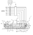
さらに一実施形態では、研磨状態測定センサ52は、図4に示すように、圧力室40,41,42,43,49のいずれかに供給される圧縮気体の圧力を測定する圧力センサであってもよく、圧力室40,41,42,43,49のいずれかに供給される圧縮気体の流量を測定する流量センサであってもよい。本実施形態では、基板保持装置1は複数の研磨状態測定センサ52を備えており、複数の研磨状態測定センサ52は、気体移送ラインF1,F2,F3,F4,F5にそれぞれ接続されている。具体的には、各研磨状態測定センサ52は、圧縮気体の流れ方向に関してロータリージョイント25の下流側に配置されている。
以下、本明細書では、気体移送ラインF1,F2,F3,F4,F5に接続される複数の研磨状態測定センサ52をそれぞれ、センサS1,S2,S3,S4,S5と呼ぶことがある。一実施形態では、基板保持装置1は、センサS1,S2,S3,S4,S5のうちの少なくとも1つを備えていてもよい。さらに一実施形態では、基板保持装置1は、圧力センサとしての研磨状態測定センサ52と流量センサとしての研磨状態測定センサ52の両方を備えていてもよい。
さらに一実施形態では、研磨状態測定センサ52は、図5に示すように研磨ヘッド9の歪を測定する歪センサであってもよい。本実施形態の一例では、研磨状態測定センサ52は、リテーナリング36の外周に取り付けられている。研磨中、ウェハWは、リテーナリング36の下流側に接触する。これにより、研磨中にウェハWと研磨パッド2との間で発生する摩擦力がリテーナリング36に作用し、リテーナリング36が歪む。本実施形態の一例では、研磨状態測定センサ52は、このリテーナリング36の歪を測定する。一実施形態では、研磨状態測定センサ52は、研磨中の研磨ヘッド9の温度上昇に伴う研磨ヘッド9の一部の部品の熱膨張による研磨ヘッド9の一部の歪を測定してもよい。この場合、歪センサとしての研磨状態測定センサ52は、研磨ヘッド9の熱膨張の影響を受けやすい箇所に接触して、または研磨ヘッド9の熱膨張の影響を受けやすい箇所に近接して配置される。このような歪センサは、歪を感知することができる圧電素子や金属抵抗体などの素子を備えている。
図2に示すように、無線ユニット68は、無線ユニット本体69と、アンテナ73を備えている。無線ユニット68は、研磨ヘッド9に設けられている。具体的には、無線ユニット本体69は、研磨ヘッド本体10の内部に配置されているが、無線ユニット68が回転系4の一部を構成する限りにおいて無線ユニット68の位置は、本実施形態に限定されない。一実施形態では、無線ユニット68は、研磨ヘッド9の外周面に固定されていてもよい。
発電装置55は、研磨状態測定センサ52および無線ユニット68に接続されており、発電装置55は、研磨状態測定センサ52および無線ユニット68に電力を供給する。言い換えれば、発電装置55が発生させた電力は、研磨状態測定センサ52および無線ユニット68の駆動に使用される。
研磨状態測定センサ52は、物理量の測定値を無線ユニット68に送信する。無線ユニット68は、無線信号の送受信機能を有し、動作制御部7との間で無線通信によって研磨状態測定センサ52から出力された物理量の測定値を動作制御部7に送信する。無線ユニット本体69は、研磨状態測定センサ52からのアナログ信号をデジタル信号に変換するADコンバータ70と、研磨状態測定センサ52から出力された物理量の測定値を含む測定データを圧縮するCPU(中央処理装置)72と、無線信号の送受信を行う送受信機71を備えている。アンテナ73は、送受信機71に接続されており、上記物理量の測定値は、アンテナ73を介して動作制御部7に送信される。
動作制御部7は、研磨状態測定センサ52が測定した物理量の測定値に基づいて、研磨状態の判定や、研磨終点の決定を行う。例えば、研磨中のウェハWと研磨パッド2との摩擦によって発生する音や、研磨ヘッド9の振動は、研磨状態(例えば、研磨面2aの状態や、ウェハWの膜の状態)によって変化する。したがって、一実施形態では、動作制御部7は研磨状態測定センサ52によって測定された音圧の変化や振動の変化に基づいて研磨終点を決定してもよい。一実施形態では、動作制御部7は、研磨状態測定センサ52で測定された物理量(温度、振動、音圧、振動、歪)を予め定められたしきい値と比較し、上記物理量が予め定められたしきい値よりも大きいときに、研磨状態が異常であると判定してもよい。
さらに一実施形態では、動作制御部7は、センサS1,S2,S3,S4,S5の圧力の測定値に基づいて、圧力レギュレータR1,R2,R3,R4,R5に指令を発し、圧力室40,41,42,43,49内の圧縮気体の圧力を調整させてもよい。さらに一実施形態では、動作制御部7は、センサS1,S2,S3,S4,S5の流量の測定値に基づいて、気体移送ラインF1,F2,F3,F4,F5のそれぞれに接続された流量制御弁(図示せず)に指令を発し、圧力室40,41,42,43,49に供給される圧縮気体の流量を制御させてもよい。これにより、研磨ヘッド9は、安定してウェハWを研磨面2aに押し付けることができる。
リテーナリング36に作用する摩擦力は、研磨状態(例えば、研磨面2aの状態や、ウェハWの膜の状態)によって変化する。したがって、一実施形態では、動作制御部7は研磨状態測定センサ52によって測定された歪の変化に基づいて研磨終点を決定してもよい。さらに一実施形態では、動作制御部7は、歪の周期的な変化に基づいてウェハWの位相を決定してもよい。
無線ユニット68は、また動作制御部7からの指令を含む信号を受信するようにも構成されている。このような指令の一例として、研磨状態測定センサ52の動作を停止する指令が挙げられる。一実施形態では、研磨状態測定センサ52が物理量の測定値を送信する機能を有している場合、無線ユニット68を省略してもよい。
図6は、基板保持装置1の他の実施形態を示す模式図である。特に説明しない本実施形態の構成および動作は、図1乃至図3を参照して説明した実施形態と同じであるので、その重複する説明を省略する。図6に示すように、本実施形態の基板保持装置1は、発電装置55が発生させた電力を蓄える蓄電器75をさらに備えている。蓄電器75は、発電装置55に接続されており、発電装置55は、電力を発生させて、蓄電器75を充電する。
蓄電器75は、研磨ヘッド9に設けられており、蓄電器75は、回転系4の一部を構成する。具体的には、蓄電器75は、研磨ヘッド本体10の内部に配置されているが、蓄電器75が回転系4の一部を構成する限りにおいて蓄電器75の位置は、本実施形態に限定されない。
蓄電器75は、研磨状態測定センサ52および無線ユニット68に接続されており、蓄電器75に蓄えられた電力を研磨状態測定センサ52および無線ユニット68に供給可能に構成されている。したがって、研磨装置の運転開始時のように発電装置55が十分な電力を発生させていないときでも安定して研磨状態測定センサ52および無線ユニット68に電力を供給することができる。蓄電器75の例として、ニッケル水素二次電池、リチウムイオン二次電池、およびキャパシタが挙げられる。本実施形態の構成は、図4および図5を参照して説明した実施形態にも適用することができる。
一例として、無線ユニット68の消費電力は約0.5Wであり、研磨状態測定センサ52の消費電力は約0.5Wであるので、蓄電池75への充電電力を1Wとすると、合計2Wの発電容量が必要となる。
一実施形態では、図7に示すように、基板保持装置1は蓄電器75の充電量(蓄電器75の電圧)を測定する電圧計76を備えていてもよい。電圧計76は、無線ユニット68に接続され、電圧計76で測定された電圧の測定値(蓄電器75の電圧、すなわち蓄電器75の充電量)は動作制御部7に送信される。
一実施形態では、動作制御部7は、電圧計76で測定された電圧の測定値(蓄電器75の充電量)に基づいて、研磨状態測定センサ52に指令を発してもよい。例えば、動作制御部7は、蓄電器75の充電量を予め定められたしきい値と比較し、蓄電器75の充電量が予め定められたしきい値よりも小さい場合は、消費電力を抑えるために研磨状態測定センサ52に指令を発して研磨状態測定センサ52の動作を停止させてもよい。
図8は、基板保持装置1のさらに他の実施形態を示す模式図である。特に説明しない本実施形態の構成および動作は、図1および図2を参照して説明した実施形態と同じであるので、その重複する説明を省略する。本実施形態では、基板保持装置1は、気体移送ラインF6と、圧力レギュレータR6を備えていない。本実施形態の発電装置55は、回転系4側に配置された回転系側コイル78と、回転系側コイル78の外側に配置された固定子(ステータ)79と、電力線82a,82bを介して固定子79に接続された電源81を備えている。
本実施形態では、電源81は、研磨ヘッド揺動アーム16の内部に配置されているが、電源81の位置は本実施形態に限定されない。電源81は、動作制御部7に電気的に接続されており、電源81の動作は動作制御部7によって制御される。
回転系側コイル78は、研磨ヘッドシャフト11に固定されており、研磨ヘッドシャフト11の周囲を囲んでいる。回転系側コイル78は、回転系4の一部を構成している。回転系側コイル78は複数のコイルの集合体である。固定子79は回転系側コイル78を囲むように配置されており、回転系側コイル78と固定子79は互いに離間している。具体的には、固定子79は、研磨ヘッド揺動アーム16に固定されている。回転系側コイル78は、研磨ヘッドシャフト11と一体に回転するが、研磨ヘッド揺動アーム16は回転しない。すなわち、固定子79は、回転系4の一部を構成せず、研磨ヘッド揺動アーム16に対する固定子79の相対的な位置は変化しない。
固定子79は、固定子79と回転系側コイル78との間に磁界を形成するように構成されている。具体的には、固定子79は、ステータコア79aと、ステータコア79aに巻かれた固定子側コイル79bとを備えている。固定子側コイル79bは複数のコイルの集合体である。固定子側コイル79bは、電力線82a,82bに接続されており、電源81から電力線82a,82bを介して固定子側コイル79bに電流を流すことにより、固定子79と回転系側コイル78との間に磁界が形成される。本実施形態の固定子79は、いわゆる電磁石である。固定子79を電磁石とすることで、固定子79に電力が供給されていない状態では磁界が発生しないため、メンテナンス時の工具が磁力によって固定子79に引き寄せられる等のリスクを回避することができる。
固定子79と回転系側コイル78との間に磁界が形成されている状態で、研磨ヘッドシャフト11を回転させることにより、回転系側コイル78は固定子79が形成する磁界の中を移動する。これにより、電磁誘導が発生し、回転系側コイル78に電流が流れる(回転系側コイル78に電力が発生する)。すなわち、本実施形態の発電装置55は、固定子79が形成する磁界と、回転系側コイル78との回転によって発生する電磁誘導を利用して電力を発生させる発電装置である。
上述のように、回転系側コイル78は、回転系4の一部を構成している。したがって、本実施形態においても、発電装置55は、回転系4内で電力を発生させる。一実施形態では、図9に示すように、固定子79は、永久磁石でもよい。この場合、基板保持装置1は、電源81を備えなくてもよい。
さらに一実施形態では、図10に示すように、基板保持装置1は、回転系側コイル78および固定子79の下方に配置された電磁シールド83を備えていてもよい。電磁シールド83は、回転系側コイル78および固定子79の下方で研磨ヘッドシャフト11を囲むように配置されており、回転系側コイル78および固定子79の下方への電磁波を遮断するように構成されている。これにより、渦電流センサを用いてウェハWの膜圧を測定する場合に、発電装置55の電磁波が渦電流センサに与える悪影響を防止することができる。本実施形態の構成は、図9を参照して説明した実施形態にも適用することができる。
さらに一実施形態では、動作制御部7は、回転速度検出器23から研磨ヘッド用モータ18の回転速度(すなわち、研磨ヘッド9の回転速度)の測定値を受け取り、研磨ヘッド用モータ18の回転速度に基づいて、電源81から固定子側コイル79bに供給される電流を制御してもよい。例えば、動作制御部7は、上記回転速度と、予め定められた下限しきい値を比較し、上記回転速度が下限しきい値よりも小さいときは、電源81に指令を発し、固定子側コイル79bに供給する電流を増加させてもよく、動作制御部7は、上記回転速度と、予め定められた上限しきい値を比較し、上記回転速度が上限しきい値よりも大きいときは、電源81に指令を発し、固定子側コイル79bに供給する電流を減少させてもよい。これにより、回転系4内で発生される電力を均一にすることが可能となり、安定した電力の供給が可能となる。
図8乃至図10を参照して説明した実施形態の構成は、図4乃至図7を参照して説明した実施形態にも適用することができる。一実施形態では、動作制御部7は、電圧計76(図7参照)で測定された電圧の測定値(蓄電器75の充電量)に基づいて、電源81から固定子側コイル79bに供給される電流を制御してもよい。例えば、動作制御部7は、蓄電器75の充電量と、予め定められたしきい値を比較し、上記回転速度が上記しきい値よりも小さいときは、電源81に指令を発し、固定子側コイル79bに供給する電流を増加させてもよい。
図11は、基板保持装置1のさらに他の実施形態を示す模式図である。特に説明しない本実施形態の構成および動作は、図1および図2を参照して説明した実施形態と同じであるので、その重複する説明を省略する。本実施形態では、基板保持装置1は、気体移送ラインF6と、圧力レギュレータR6を備えていない。本実施形態では、発電装置55は、振動エネルギーを利用した発電装置である。具体的には、本実施形態の発電装置55は、研磨中の振動を利用して回転系4内で電力を発生させる振動発電装置である。発電装置55は、振動による圧力を電力に変換する圧電素子85を備えている。本実施形態においても、発電装置55は、回転系4内で電力を発生させる。
発電装置55は、研磨ヘッド9に設けられている。具体的には、発電装置55は、研磨ヘッド本体10の内部に配置されている。本実施形態の発電装置55は、回転系4の一部を構成している。発電装置55が回転系4の一部を構成する限りにおいて、振動発電装置としての発電装置55の位置は本実施形態に限定されない。一実施形態では、発電装置55は、研磨ヘッド本体10の上面に固定されていてもよい。本実施形態の構成は、図4乃至図7を参照して説明した実施形態にも適用することができる。
図12は、基板保持装置1のさらに他の実施形態を示す模式図である。特に説明しない本実施形態の構成および動作は、図1および図2を参照して説明した実施形態と同じであるので、その重複する説明を省略する。本実施形態では、基板保持装置1は、気体移送ラインF6と、圧力レギュレータR6を備えていない。本実施形態では、発電装置55は、熱エネルギーを利用した発電装置である。具体的には、本実施形態の発電装置55は、ウェハWと研磨パッド2との摩擦などによる摩擦熱や、ウェハWと研磨液(スラリー)との化学反応による化学反応熱などの研磨中に発生する熱を利用して回転系4内で電力を発生させる熱発電装置である。
発電装置55は、ゼーベック効果によって熱エネルギーを電気エネルギーに変換するゼーベック素子87を備えている。本実施形態においても、発電装置55は、回転系4内で電力を発生させる。発電装置55は、研磨ヘッド9に設けられている。具体的には、発電装置55は、研磨ヘッド9の外側に配置されている。より具体的には、発電装置55は、研磨ヘッド本体10の上面に固定されている。研磨中に発生する熱により、研磨中、研磨ヘッド9の温度は上昇する。ゼーベック素子87は、研磨中の研磨ヘッド9の温度と、大気の温度との温度差を電圧に変換する。これにより、発電装置55は電力を発生させる。
本実施形態の発電装置55は、回転系4の一部を構成している。熱発電装置としての発電装置55の位置は、研磨ヘッド9の外側かつ研磨ヘッド9に接触して配置される限りにおいて、本実施形態に限定されない。本実施形態の構成は、図4乃至図7を参照して説明した実施形態にも適用することができる。
図13は、基板保持装置1のさらに他の実施形態を示す模式図である。特に説明しない本実施形態の構成および動作は、図1および図2を参照して説明した実施形態と同じであるので、その重複する説明を省略する。本実施形態では、基板保持装置1は、気体移送ラインF6と、圧力レギュレータR6を備えていない。本実施形態では、発電装置55は、光エネルギーを利用した発電装置(光発電装置)である。本実施形態の発電装置55は、光電変換素子88と、光電変換素子88に光を照射する光源89を備えている。
光源89から光電変換素子88に光を照射することによって、光電変換素子88は、光源89からの光エネルギーを電気エネルギーに変換する。これにより、発電装置55は、電力を発生させる。光電変換素子88の一例として、太陽電池が挙げられる。
本実施形態においても、発電装置55は、回転系4内で電力を発生させる。光電変換素子88は、研磨ヘッド9に設けられている。具体的には、発電装置55は、研磨ヘッド9の外側に配置されている。より具体的には、発電装置55は、研磨ヘッド本体10の上面に固定されている。光電変換素子88は、回転系4の一部を構成している。一方、光源89は研磨ヘッド9の外側に配置されており、その位置は固定されている。したがって、光源89は、回転系4の一部を構成しない。光源89は、研磨ヘッド本体10の上面全体を照射可能に構成されている。したがって、研磨中の光電変換素子88の位置に関わらず、光電変換素子88に光を照射することができる。本実施形態の構成は、図4乃至図7を参照して説明した実施形態にも適用することができる。
図14は、基板保持装置1のさらに他の実施形態を示す模式図である。特に説明しない本実施形態の構成および動作は、図1乃至図3を参照して説明した実施形態と同じであるので、その重複する説明を省略する。本実施形態では、基板保持装置1は、気体移送ラインF1,F2,F3,F4,F5の内部に形成された圧縮気体の流路を開閉する開閉弁V1,V2,V3,V4,V5をさらに備えている。開閉弁V1,V2,V3,V4,V5は、電気で駆動する(電力を必要とする)弁であり、開閉弁V1,V2,V3,V4,V5の一例として電磁弁が挙げられる。開閉弁V1,V2,V3,V4,V5は、気体移送ラインF1,F2,F3,F4,F5にそれぞれ取り付けられている。
開閉弁V1,V2,V3,V4,V5は、圧縮気体の流れ方向においてロータリージョイント25の下流側に配置されている。したがって、開閉弁V1,V2,V3,V4,V5は、回転系4の一部を構成する。開閉弁V1,V2,V3,V4,V5は、発電装置55に接続されており、発電装置55は、開閉弁V1,V2,V3,V4,V5に電力を供給する。言い換えれば、発電装置55が発生させた電力は、開閉弁V1,V2,V3,V4,V5の動作に使用される。開閉弁V1,V2,V3,V4,V5は、無線ユニット68に接続されている。一実施形態では、開閉弁V1,V2,V3,V4,V5の動作は動作制御部7によって制御される。本実施形態の構成は、図4乃至図13を参照して説明した実施形態にも適用することができる。
図15は、基板保持装置1のさらに他の実施形態を示す模式図である。特に説明しない本実施形態の構成および動作は、図7を参照して説明した実施形態と同じであるので、その重複する説明を省略する。本実施形態の基板保持装置1は、研磨ヘッド9に設けられた回転系側制御部91をさらに備えている。回転系側制御部91は、発電装置55に接続されており、発電装置55が発生させた電力は、回転系側制御部91の動作に使用される。
回転系側制御部91は、回転系4の一部を構成している。回転系側制御部91は、研磨ヘッド本体10の内部に配置されている。回転系側制御部91は、回転系4の一部を構成している。回転系側制御部91が回転系4を構成する限りにおいて、回転系側制御部91の位置は本実施形態に限定されない。
回転系側制御部91は、プログラムが格納された記憶装置91aと、プログラムに含まれる命令に従って演算を実行する処理装置91bを備えている。処理装置91bは、記憶装置91aに格納されているプログラムに含まれる命令に従って演算を行うCPU(中央処理装置)またはGPU(グラフィックプロセッシングユニット)などを含む。記憶装置91aは、処理装置91bがアクセス可能な主記憶装置(例えばランダムアクセスメモリ)と、データおよびプログラムを格納する補助記憶装置(例えば、ハードディスクドライブまたはソリッドステートドライブ)を備えている。回転系側制御部91は、少なくとも1台のコンピュータから構成されている。
回転系側制御部91は、電圧計76に接続されており、電圧計76は電圧の測定値(蓄電器75の充電量)を回転系側制御部91に送信する。回転系側制御部91は、蓄電器75の充電量に基づいてエネルギー管理を行う。一実施形態では、回転系側制御部91は、蓄電器75の充電量を予め定められたしきい値と比較し、蓄電器75の充電量が予め定められたしきい値よりも小さい場合は、消費電力を抑えるために研磨状態測定センサ52に指令を発して研磨状態測定センサ52の動作を停止させてもよい。
本実施形態の構成は、図1乃至図6および図8乃至図14を参照して説明した実施形態にも適用することができる。回転系側制御部91は、無線ユニット68に接続されている。回転系側制御部91は、本体側(基板保持装置1の回転系4を除く部分)との無線通信により、本体側の発電に関わる制御を行ってもよい。例えば、回転系側制御部91は、研磨ヘッド用モータ18の回転速度を決定し、決定した回転速度を研磨ヘッド用モータ18に送信してもよい。さらに一実施形態では、回転系側制御部91は、蓄電器75の充電量に基づいて電源81から固定子側コイル79bに供給される電流を制御してもよい。動作制御部7は、蓄電器75の充電量と、予め定められたしきい値を比較し、上記回転速度が上記しきい値よりも小さいときは、電源81(図8参照)に指令を発し、固定子側コイル79bに供給する電流を増加させてもよい。
さらに一実施形態では、回転系側制御部91は、回転速度検出器23から研磨ヘッド用モータ18の回転速度(すなわち、研磨ヘッド9の回転速度)の測定値を受け取り、研磨ヘッド用モータ18の回転速度に基づいて、電源81から固定子側コイル79bに供給される電流を制御してもよい。例えば、回転系側制御部91は、上記回転速度と、予め定められた下限しきい値を比較し、上記回転速度が下限しきい値よりも小さいときは、電源81に指令を発し、固定子側コイル79bに供給する電流を増加させてもよく、回転系側制御部91は、上記回転速度と、予め定められた上限しきい値を比較し、上記回転速度が上限しきい値よりも大きいときは、電源81に指令を発し、固定子側コイル79bに供給する電流を減少させてもよい。
上述したように、図1乃至図15を参照して説明した各実施形態の発電装置55の少なくとも一部は、回転系4の一部を構成している。図1乃至図15を参照して説明した発電装置55は、研磨ヘッド9と一体に回転する部品(研磨状態測定センサ52や開閉弁V1~V5など)に供給する電力を、回転系4内で発生させる。したがって、研磨ヘッド9と一体に回転し、かつ電力を必要とする部品に容易に電力を供給することができる。また、ロータリージョイント25を介して上記部品に電力を供給した場合の、ロータリージョイント25のロータリーコネクタの接触不良、ロータリーコネクタの故障、漏電等のリスクを回避することができる。
上述した実施形態は、本発明が属する技術分野における通常の知識を有する者が本発明を実施できることを目的として記載されたものである。上記実施形態の種々の変形例は、当業者であれば当然になしうることであり、本発明の技術的思想は他の実施形態にも適用しうる。したがって、本発明は、記載された実施形態に限定されることはなく、特許請求の範囲によって定義される技術的思想に従った最も広い範囲に解釈されるものである。
本発明は、ウェハなどの基板を保持する基板保持装置に利用可能であり、特に研磨装置に使用される基板保持装置に利用可能である。
1 基板保持装置
2 研磨パッド
2a 研磨面
3 研磨テーブル
3a テーブル軸
4 回転系
5 研磨液供給ノズル
7 動作制御部
9 研磨ヘッド
10 研磨ヘッド本体
11 研磨ヘッドシャフト
12 回転筒
13 テーブル回転モータ
14 タイミングプーリ
16 研磨ヘッド揺動アーム
18 研磨ヘッド用モータ
19 タイミングベルト
20 タイミングプーリ
21 支軸
23 回転速度検出器
25 ロータリージョイント
26 軸受
27 上下動機構
28 ブリッジ
29 支持台
30 支柱
32 ボールねじ
32a ねじ軸
32b ナット
34 サーボモータ
36 リテーナリング
38 弾性膜
38a 押圧面
40~43 圧力室
45 リテーナリング押圧機構
46 ピストン
48 ローリングダイヤフラム
49 圧力室(リテーナリング圧力室)
50 ドライブリング
52 研磨状態測定センサ
55 発電装置
57 モータ
58 回転軸
60 ファン
62 固定部材
63 ケーシング
65a 吸気口
65b 排気口
68 無線ユニット
69 無線ユニット本体
70 ADコンバータ
71 送受信機
72 CPU
73 アンテナ
75 蓄電器
76 電圧計
78 回転系側コイル
79 固定子
79a ステータコア
79b 固定子側コイル
81 電源
82a,82b 電力線
83 電磁シールド
85 圧電素子
87 ゼーベック素子
88 光電変換素子
89 光源
91 回転系側制御部
F1,F2,F3,F4,F5,F6 気体移送ライン
V1,V2,V3,V4,V5 開閉弁
2 研磨パッド
2a 研磨面
3 研磨テーブル
3a テーブル軸
4 回転系
5 研磨液供給ノズル
7 動作制御部
9 研磨ヘッド
10 研磨ヘッド本体
11 研磨ヘッドシャフト
12 回転筒
13 テーブル回転モータ
14 タイミングプーリ
16 研磨ヘッド揺動アーム
18 研磨ヘッド用モータ
19 タイミングベルト
20 タイミングプーリ
21 支軸
23 回転速度検出器
25 ロータリージョイント
26 軸受
27 上下動機構
28 ブリッジ
29 支持台
30 支柱
32 ボールねじ
32a ねじ軸
32b ナット
34 サーボモータ
36 リテーナリング
38 弾性膜
38a 押圧面
40~43 圧力室
45 リテーナリング押圧機構
46 ピストン
48 ローリングダイヤフラム
49 圧力室(リテーナリング圧力室)
50 ドライブリング
52 研磨状態測定センサ
55 発電装置
57 モータ
58 回転軸
60 ファン
62 固定部材
63 ケーシング
65a 吸気口
65b 排気口
68 無線ユニット
69 無線ユニット本体
70 ADコンバータ
71 送受信機
72 CPU
73 アンテナ
75 蓄電器
76 電圧計
78 回転系側コイル
79 固定子
79a ステータコア
79b 固定子側コイル
81 電源
82a,82b 電力線
83 電磁シールド
85 圧電素子
87 ゼーベック素子
88 光電変換素子
89 光源
91 回転系側制御部
F1,F2,F3,F4,F5,F6 気体移送ライン
V1,V2,V3,V4,V5 開閉弁
Claims (10)
- 基板を研磨する研磨装置に使用される基板保持装置であって、
前記基板を研磨面に押し付ける研磨ヘッドと、
前記ヘッドに連結された研磨ヘッドシャフトと、
前記研磨ヘッドおよび前記研磨ヘッドシャフトを少なくとも含む回転系内で電力を発生させる発電装置と、を備えている、基板保持装置。 - 前記研磨ヘッドの内部を延びる気体移送ラインをさらに備え、
前記発電装置は、前記気体移送ラインに接続されており、
前記発電装置は、前記気体移送ラインを流れる圧縮気体を利用して電力を発生させる風力発電装置である、請求項1に記載の基板保持装置。 - 前記発電装置は、
前記回転系の一部を構成する回転系側コイルと、
前記回転側コイルの外側に配置され、かつ前記回転系側コイルとの間に磁界を形成する固定子を備え、
前記発電装置は、前記固定子が形成する磁界と、前記回転系側コイルの回転とによって発生する電磁誘導を利用して電力を発生させる発電装置である、請求項1に記載の基板保持装置。 - 前記発電装置の少なくとも一部は、前記回転系の一部を構成し、
前記発電装置は、振動エネルギー、熱エネルギー、または光エネルギーのいずれかを利用した発電装置である、請求項1に記載の基板保持装置。 - 前記発電装置が発生させた電力を蓄える蓄電器をさらに備えている、請求項1乃至4のいずれか一項に記載の基板保持装置。
- 前記蓄電器は、ニッケル水素二次電池、リチウムイオン二次電池、またはキャパシタのいずれかである、請求項5に記載の基板保持装置。
- 前記回転系の一部を構成する研磨状態測定センサをさらに備え、
前記発電装置は、前記研磨状態測定センサに電力を供給するように構成されている、請求項1乃至6のいずれか一項に記載の基板保持装置。 - 前記研磨状態測定センサは、研磨ヘッドの温度および/または研磨ヘッドの周囲温度を測定する温度センサ、研磨中の音圧を測定する音センサ、前記研磨ヘッドの振動を測定する振動センサ、前記研磨ヘッドに形成された圧力室に供給される圧縮気体の圧力を測定する圧力センサ、前記圧縮気体の流量を測定する流量センサ、または前記研磨ヘッドの歪を測定する歪センサのいずれかである、請求項7に記載の基板保持装置。
- 前記研磨ヘッドに形成された圧力室に供給される圧縮気体の流路を開閉する開閉弁をさらに備え、
前記発電装置は、前記開閉弁に電力を供給するように構成されており、
前記開閉弁は、前記回転系の一部を構成している、請求項1乃至6のいずれか一項に記載の基板保持装置。 - 前記研磨状態測定センサが測定した物理量の測定値を、前記研磨装置の動作制御部に送信する無線ユニットをさらに備え、
前記無線ユニットは、前記回転系の一部を構成している、請求項7または8に記載の基板保持装置。
Applications Claiming Priority (2)
| Application Number | Priority Date | Filing Date | Title |
|---|---|---|---|
| JP2020191381A JP2022080370A (ja) | 2020-11-18 | 2020-11-18 | 基板保持装置 |
| JP2020-191381 | 2020-11-18 |
Publications (1)
| Publication Number | Publication Date |
|---|---|
| WO2022107553A1 true WO2022107553A1 (ja) | 2022-05-27 |
Family
ID=81708941
Family Applications (1)
| Application Number | Title | Priority Date | Filing Date |
|---|---|---|---|
| PCT/JP2021/039279 Ceased WO2022107553A1 (ja) | 2020-11-18 | 2021-10-25 | 基板保持装置 |
Country Status (3)
| Country | Link |
|---|---|
| JP (1) | JP2022080370A (ja) |
| TW (1) | TW202224857A (ja) |
| WO (1) | WO2022107553A1 (ja) |
Families Citing this family (2)
| Publication number | Priority date | Publication date | Assignee | Title |
|---|---|---|---|---|
| US20240139900A1 (en) | 2022-10-27 | 2024-05-02 | Applied Materials, Inc. | Acoustic carrier head monitoring |
| CN117381659B (zh) * | 2023-10-13 | 2025-05-06 | 苏州铼铂机电科技有限公司 | 压力可测量可控制调节的半导体材料研磨加工夹具及加工方法 |
Citations (10)
| Publication number | Priority date | Publication date | Assignee | Title |
|---|---|---|---|---|
| JPH10337654A (ja) * | 1997-06-04 | 1998-12-22 | Ebara Corp | ポリッシング装置 |
| JP2000094312A (ja) * | 1998-09-29 | 2000-04-04 | Ebara Corp | ポリッシング装置 |
| US20060258263A1 (en) * | 2005-05-10 | 2006-11-16 | Nikon Corporation | Chemical mechanical polishing end point detection apparatus and method |
| KR20120086077A (ko) * | 2011-01-25 | 2012-08-02 | 오찬권 | 광섬유케이블이 포함된 투과성시트, 이를 이용한 cmp공정에서의 연마종결점 검출방법 및 장치 |
| JP2014166678A (ja) * | 2014-04-18 | 2014-09-11 | Ebara Corp | 研磨装置 |
| JP2015100911A (ja) * | 2013-11-28 | 2015-06-04 | 株式会社荏原製作所 | 研磨装置 |
| KR20160145305A (ko) * | 2015-06-10 | 2016-12-20 | 주식회사 케이씨텍 | 화학 기계적 연마 장치 |
| JP2017528904A (ja) * | 2014-06-16 | 2017-09-28 | アプライド マテリアルズ インコーポレイテッドApplied Materials,Incorporated | 一体型センサを有する化学機械研磨保持リング |
| JP2018174230A (ja) * | 2017-03-31 | 2018-11-08 | 株式会社荏原製作所 | 基板処理装置 |
| JP2018186148A (ja) * | 2017-04-25 | 2018-11-22 | 株式会社荏原製作所 | 基板処理装置の運転方法 |
-
2020
- 2020-11-18 JP JP2020191381A patent/JP2022080370A/ja active Pending
-
2021
- 2021-10-25 WO PCT/JP2021/039279 patent/WO2022107553A1/ja not_active Ceased
- 2021-11-04 TW TW110141089A patent/TW202224857A/zh unknown
Patent Citations (10)
| Publication number | Priority date | Publication date | Assignee | Title |
|---|---|---|---|---|
| JPH10337654A (ja) * | 1997-06-04 | 1998-12-22 | Ebara Corp | ポリッシング装置 |
| JP2000094312A (ja) * | 1998-09-29 | 2000-04-04 | Ebara Corp | ポリッシング装置 |
| US20060258263A1 (en) * | 2005-05-10 | 2006-11-16 | Nikon Corporation | Chemical mechanical polishing end point detection apparatus and method |
| KR20120086077A (ko) * | 2011-01-25 | 2012-08-02 | 오찬권 | 광섬유케이블이 포함된 투과성시트, 이를 이용한 cmp공정에서의 연마종결점 검출방법 및 장치 |
| JP2015100911A (ja) * | 2013-11-28 | 2015-06-04 | 株式会社荏原製作所 | 研磨装置 |
| JP2014166678A (ja) * | 2014-04-18 | 2014-09-11 | Ebara Corp | 研磨装置 |
| JP2017528904A (ja) * | 2014-06-16 | 2017-09-28 | アプライド マテリアルズ インコーポレイテッドApplied Materials,Incorporated | 一体型センサを有する化学機械研磨保持リング |
| KR20160145305A (ko) * | 2015-06-10 | 2016-12-20 | 주식회사 케이씨텍 | 화학 기계적 연마 장치 |
| JP2018174230A (ja) * | 2017-03-31 | 2018-11-08 | 株式会社荏原製作所 | 基板処理装置 |
| JP2018186148A (ja) * | 2017-04-25 | 2018-11-22 | 株式会社荏原製作所 | 基板処理装置の運転方法 |
Also Published As
| Publication number | Publication date |
|---|---|
| TW202224857A (zh) | 2022-07-01 |
| JP2022080370A (ja) | 2022-05-30 |
Similar Documents
| Publication | Publication Date | Title |
|---|---|---|
| WO2022107553A1 (ja) | 基板保持装置 | |
| US10513008B2 (en) | Chemical mechanical polishing smart ring | |
| US6612900B2 (en) | Method and apparatus for wireless transfer of chemical-mechanical planarization measurements | |
| US10946496B2 (en) | Chemical mechanical polishing retaining ring with integrated sensor | |
| US9381614B2 (en) | Pressure regulator, polishing apparatus having the pressure regulator, and polishing method | |
| US9149903B2 (en) | Polishing apparatus having substrate holding apparatus | |
| US6926585B2 (en) | Pressure control system and polishing apparatus | |
| JP4484413B2 (ja) | 力制御方式研磨のためのスピンドル組立体 | |
| CN115741427B (zh) | 一种用于化学机械抛光的承载头、抛光系统和抛光方法 | |
| CN210499744U (zh) | 一种压力控制装置和化学机械抛光装置 | |
| CN112405333B (zh) | 一种化学机械抛光装置和抛光方法 | |
| CN115962936A (zh) | 一种高速滚动轴承高温环境模拟试验装置 | |
| WO2000045993A1 (en) | Wafer holder and polishing device | |
| TWI327091B (ja) | ||
| CN218658384U (zh) | 一种用于化学机械抛光的承载头和抛光系统 | |
| CN222553229U (zh) | 研磨垫修整器及化学机械研磨设备 | |
| JP2021137908A (ja) | 研磨ヘッドシステムおよび研磨装置 | |
| US20240066658A1 (en) | Polishing head system and polishing method | |
| TW202241640A (zh) | 具備檢測器的量測晶圓、及其使用方法 |
Legal Events
| Date | Code | Title | Description |
|---|---|---|---|
| 121 | Ep: the epo has been informed by wipo that ep was designated in this application |
Ref document number: 21894427 Country of ref document: EP Kind code of ref document: A1 |
|
| NENP | Non-entry into the national phase |
Ref country code: DE |
|
| 122 | Ep: pct application non-entry in european phase |
Ref document number: 21894427 Country of ref document: EP Kind code of ref document: A1 |