WO2022107259A1 - 情報処理システム、コントローラ、情報処理方法、情報処理プログラム - Google Patents
情報処理システム、コントローラ、情報処理方法、情報処理プログラム Download PDFInfo
- Publication number
- WO2022107259A1 WO2022107259A1 PCT/JP2020/043072 JP2020043072W WO2022107259A1 WO 2022107259 A1 WO2022107259 A1 WO 2022107259A1 JP 2020043072 W JP2020043072 W JP 2020043072W WO 2022107259 A1 WO2022107259 A1 WO 2022107259A1
- Authority
- WO
- WIPO (PCT)
- Prior art keywords
- viscosity
- initial position
- stick
- magnetic field
- information processing
- Prior art date
Links
- 230000010365 information processing Effects 0.000 title claims abstract description 78
- 238000003672 processing method Methods 0.000 title claims description 4
- 238000006073 displacement reaction Methods 0.000 claims abstract description 69
- 239000011554 ferrofluid Substances 0.000 claims abstract description 12
- 238000000034 method Methods 0.000 claims description 15
- 238000001514 detection method Methods 0.000 claims description 10
- 239000012530 fluid Substances 0.000 claims description 10
- 230000003247 decreasing effect Effects 0.000 claims description 3
- 230000033001 locomotion Effects 0.000 description 35
- 238000010586 diagram Methods 0.000 description 32
- 230000008859 change Effects 0.000 description 31
- 230000001276 controlling effect Effects 0.000 description 21
- 238000004891 communication Methods 0.000 description 10
- 238000012545 processing Methods 0.000 description 9
- 238000012937 correction Methods 0.000 description 7
- 230000014509 gene expression Effects 0.000 description 6
- 238000012546 transfer Methods 0.000 description 6
- 238000006243 chemical reaction Methods 0.000 description 5
- 230000006870 function Effects 0.000 description 5
- 230000007246 mechanism Effects 0.000 description 5
- 230000004043 responsiveness Effects 0.000 description 5
- 238000004364 calculation method Methods 0.000 description 4
- 230000007423 decrease Effects 0.000 description 4
- 238000011084 recovery Methods 0.000 description 3
- 230000033228 biological regulation Effects 0.000 description 2
- 230000005540 biological transmission Effects 0.000 description 2
- 239000011159 matrix material Substances 0.000 description 2
- 230000004044 response Effects 0.000 description 2
- 240000004050 Pentaglottis sempervirens Species 0.000 description 1
- 235000004522 Pentaglottis sempervirens Nutrition 0.000 description 1
- 230000006872 improvement Effects 0.000 description 1
- 230000004048 modification Effects 0.000 description 1
- 238000012986 modification Methods 0.000 description 1
- 230000003287 optical effect Effects 0.000 description 1
- 230000001105 regulatory effect Effects 0.000 description 1
- 239000007787 solid Substances 0.000 description 1
Images


Classifications
-
- G—PHYSICS
- G06—COMPUTING; CALCULATING OR COUNTING
- G06F—ELECTRIC DIGITAL DATA PROCESSING
- G06F3/00—Input arrangements for transferring data to be processed into a form capable of being handled by the computer; Output arrangements for transferring data from processing unit to output unit, e.g. interface arrangements
- G06F3/01—Input arrangements or combined input and output arrangements for interaction between user and computer
- G06F3/03—Arrangements for converting the position or the displacement of a member into a coded form
- G06F3/033—Pointing devices displaced or positioned by the user, e.g. mice, trackballs, pens or joysticks; Accessories therefor
- G06F3/038—Control and interface arrangements therefor, e.g. drivers or device-embedded control circuitry
-
- G—PHYSICS
- G06—COMPUTING; CALCULATING OR COUNTING
- G06F—ELECTRIC DIGITAL DATA PROCESSING
- G06F3/00—Input arrangements for transferring data to be processed into a form capable of being handled by the computer; Output arrangements for transferring data from processing unit to output unit, e.g. interface arrangements
- G06F3/01—Input arrangements or combined input and output arrangements for interaction between user and computer
- G06F3/03—Arrangements for converting the position or the displacement of a member into a coded form
- G06F3/033—Pointing devices displaced or positioned by the user, e.g. mice, trackballs, pens or joysticks; Accessories therefor
- G06F3/0338—Pointing devices displaced or positioned by the user, e.g. mice, trackballs, pens or joysticks; Accessories therefor with detection of limited linear or angular displacement of an operating part of the device from a neutral position, e.g. isotonic or isometric joysticks
-
- G—PHYSICS
- G05—CONTROLLING; REGULATING
- G05G—CONTROL DEVICES OR SYSTEMS INSOFAR AS CHARACTERISED BY MECHANICAL FEATURES ONLY
- G05G9/00—Manually-actuated control mechanisms provided with one single controlling member co-operating with two or more controlled members, e.g. selectively, simultaneously
- G05G9/02—Manually-actuated control mechanisms provided with one single controlling member co-operating with two or more controlled members, e.g. selectively, simultaneously the controlling member being movable in different independent ways, movement in each individual way actuating one controlled member only
- G05G9/04—Manually-actuated control mechanisms provided with one single controlling member co-operating with two or more controlled members, e.g. selectively, simultaneously the controlling member being movable in different independent ways, movement in each individual way actuating one controlled member only in which movement in two or more ways can occur simultaneously
- G05G9/047—Manually-actuated control mechanisms provided with one single controlling member co-operating with two or more controlled members, e.g. selectively, simultaneously the controlling member being movable in different independent ways, movement in each individual way actuating one controlled member only in which movement in two or more ways can occur simultaneously the controlling member being movable by hand about orthogonal axes, e.g. joysticks
-
- G—PHYSICS
- G06—COMPUTING; CALCULATING OR COUNTING
- G06F—ELECTRIC DIGITAL DATA PROCESSING
- G06F3/00—Input arrangements for transferring data to be processed into a form capable of being handled by the computer; Output arrangements for transferring data from processing unit to output unit, e.g. interface arrangements
- G06F3/01—Input arrangements or combined input and output arrangements for interaction between user and computer
- G06F3/016—Input arrangements with force or tactile feedback as computer generated output to the user
-
- G—PHYSICS
- G05—CONTROLLING; REGULATING
- G05G—CONTROL DEVICES OR SYSTEMS INSOFAR AS CHARACTERISED BY MECHANICAL FEATURES ONLY
- G05G9/00—Manually-actuated control mechanisms provided with one single controlling member co-operating with two or more controlled members, e.g. selectively, simultaneously
- G05G9/02—Manually-actuated control mechanisms provided with one single controlling member co-operating with two or more controlled members, e.g. selectively, simultaneously the controlling member being movable in different independent ways, movement in each individual way actuating one controlled member only
- G05G9/04—Manually-actuated control mechanisms provided with one single controlling member co-operating with two or more controlled members, e.g. selectively, simultaneously the controlling member being movable in different independent ways, movement in each individual way actuating one controlled member only in which movement in two or more ways can occur simultaneously
- G05G9/047—Manually-actuated control mechanisms provided with one single controlling member co-operating with two or more controlled members, e.g. selectively, simultaneously the controlling member being movable in different independent ways, movement in each individual way actuating one controlled member only in which movement in two or more ways can occur simultaneously the controlling member being movable by hand about orthogonal axes, e.g. joysticks
- G05G2009/04766—Manually-actuated control mechanisms provided with one single controlling member co-operating with two or more controlled members, e.g. selectively, simultaneously the controlling member being movable in different independent ways, movement in each individual way actuating one controlled member only in which movement in two or more ways can occur simultaneously the controlling member being movable by hand about orthogonal axes, e.g. joysticks providing feel, e.g. indexing means, means to create counterforce
-
- G—PHYSICS
- G06—COMPUTING; CALCULATING OR COUNTING
- G06F—ELECTRIC DIGITAL DATA PROCESSING
- G06F2203/00—Indexing scheme relating to G06F3/00 - G06F3/048
- G06F2203/01—Indexing scheme relating to G06F3/01
- G06F2203/015—Force feedback applied to a joystick
Definitions
- the present invention relates to an information processing system including at least a controller having an operator such as a button or a stick, a controller, an information processing method, and an information processing program.
- controllers equipped with controls such as buttons and sticks have been known.
- an object of the present invention is to provide an information processing system, a controller, an information processing method, and an information processing program that can improve the amount and feeling of information received by a user when operating an operator.
- An example of the configuration is a stick that is displaced from the initial position by user operation, a return force addition part that applies a return force that returns the displaced stick position to the initial position, and a stick whose viscosity changes according to the strength of the magnetic field.
- Controls a controller equipped with a resistance part using a magnetic viscous fluid that acts as a resistance when shifting from the initial position to the initial position, a magnetic field generating part that applies a magnetic field to the magnetic viscous fluid, and a magnetic field generating part. It is an information processing system equipped with a possible circuit. The circuit changes the strength of the magnetic field so that when the displacement direction of the stick is in the direction approaching the initial position, the viscosity is higher than in the case where the displacement direction is away from the initial position. Let me.
- the circuit may change the viscosity of the ferrofluid by controlling the amplitude, frequency, and application time of the current applied to the magnetic field. Further, when the displacement direction is a direction approaching the initial position, the viscosity may be controlled to be increased by increasing the amplitude or application time as compared with the case where the displacement direction is away from the initial position. good.
- the displacement direction of the stick is the direction approaching the initial position, it will be the same direction as the return force.
- the return force is applied in the opposite direction. Therefore, in the former case, it is possible to suppress the variation in the resistance feeling between the two by increasing the viscosity and increasing the resistance feeling as compared with the latter case.
- the return force adding means may be configured so that the return force increases as the position of the stick is farther from the initial position. Then, in the circuit, when the displacement direction of the stick is a direction away from the initial position, the amplitude or the application time may be reduced as the position of the stick becomes farther from the initial position.
- the viscosity can be balanced with the restoring force by reducing the viscosity as the distance from the initial position increases.
- the circuit may change the viscosity of the amplitude, frequency, and application time by changing the amplitude and / or the application time without changing the frequency.
- the viscosity of the magnetic viscous fluid when the viscosity of the magnetic viscous fluid is changed by using the amplitude, frequency, and application time of the current applied to the magnetic field, the current amplitude and / or the application time are adjusted while the frequency remains constant. By doing so, control is performed to change the viscosity.
- the operation feeling associated with the adjustment should be constant to some extent. It is possible to prevent the user from feeling a big change.
- the circuit may be changed so as to increase the viscosity by increasing the amplitude and keeping or decreasing the application time.
- the controller may further include a direction detection unit that detects the displacement direction of the stick. Then, the strength of the magnetic field may be changed based on the displacement direction detected by the direction detection unit.
- the controller is information output from system software for controlling an information processing system or a predetermined application operating on the information processing system, and specifies the viscous state of the magnetic viscous fluid.
- the viscosity designation information which is the information to be used, may be corrected based on the detection direction, and the strength of the magnetic field may be changed based on the corrected viscosity designation information.
- the controller may further include a library storage unit that stores a preset library in which a plurality of information indicating the viscosity in which a predetermined viscosity state is realized can be included as a preset. Further, based on the information for specifying one of the presets output from the system software for controlling the information processing system or the predetermined application running on the information processing system, the predetermined preset corresponding to the specified preset is specified. Information indicating the viscosity of the may be obtained from the preset library. Then, the acquired information may be corrected based on the detection direction, and the strength of the magnetic field may be changed based on the corrected viscosity designation information.
- the viscosity can be set simply by specifying a preset. As a result, the burden on the developer of the application or the like can be reduced.
- FIG. 1 is a diagram showing a configuration of an information processing system 1.
- FIG. 2 is a functional block diagram showing an example of the internal configuration of the information processing apparatus main body 2.
- FIG. 3 is a functional block diagram showing the internal configuration of the controller 4.
- FIG. 4 is a perspective view of the stick device.
- FIG. 5 is a schematic diagram showing the positional relationship of each part of the stick device.
- FIG. 6 is a schematic diagram showing the positional relationship of each part of the stick device.
- FIG. 7 is a schematic diagram showing the positional relationship of each part of the stick device.
- FIG. 8 is a schematic diagram for explaining a configuration example of the MRF unit.
- FIG. 9 is a functional block diagram showing the internal configuration of the analog stick 42.
- FIG. 10 is a diagram for explaining the software hierarchy.
- FIG. 10 is a diagram for explaining the software hierarchy.
- FIG. 11 is a diagram for explaining the range of motion information.
- FIG. 12 is a diagram for explaining the range of motion information.
- FIG. 13 is a diagram for explaining the control pattern A.
- FIG. 14 is a diagram for explaining the control pattern B.
- FIG. 15 is a diagram for explaining the control pattern C.
- FIG. 16 is a diagram for explaining the control pattern D.
- FIG. 17 is a diagram for explaining the principle of control in the first embodiment.
- FIG. 18 is a diagram for explaining the principle of control in the second embodiment.
- FIG. 19 is a diagram for explaining the principle of control in the second embodiment.
- FIG. 20 is a diagram for explaining the principle of control in the second embodiment.
- FIG. 21 is a diagram for explaining the principle of control in the second embodiment.
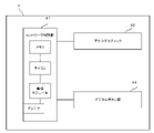
- FIG. 1 is a diagram schematically showing a configuration of an information processing system according to the present embodiment.
- the information processing system 1 includes an information processing apparatus main body 2, a monitor 3, and a controller 4.
- predetermined information processing is executed in the information processing apparatus main body 2, and predetermined images and sounds generated as a result of the processing are output to the monitor 3.
- the controller 4 has a built-in communication unit capable of wireless communication, and is used by being wirelessly connected to the information processing apparatus main body 2.
- the information processing apparatus main body 2 and the controller 4 may be connected by wire.
- Data indicating the contents of the user's operation performed on the controller 4 is transmitted from the controller 4 to the information processing apparatus main body 2. Further, data for controlling the operation of the controller 4 is also transmitted from the information processing apparatus main body 2 to the controller 4.
- the controller control unit (described later) built in the controller 4 performs various controls of the controller 4 including transmission / reception of such data.
- FIG. 2 is a functional block diagram showing an example of the internal configuration of the information processing apparatus main body 2.
- the information processing apparatus main body 2 includes a processor 11.
- the processor 11 is a circuit for controlling the information processing apparatus main body 2.
- the processor 11 executes various kinds of information processing executed in the information processing apparatus main body 2. For example, it may be configured only by a CPU (Central Processing Unit), or may be configured by a System (System-on-a-chip) including a plurality of functions such as a CPU function and a GPU (Graphics Processing Unit) function. ..
- the processor 11 executes various information processing by executing an information processing program (for example, a predetermined application program) stored in the storage unit 12.
- the storage unit 12 may be, for example, an internal storage medium such as a flash memory or a DRAM (Dynamic Random Access Memory), or may be configured to use an external storage medium or the like installed in a slot (not shown).
- the video / audio output unit 14 is electrically connected to the processor 11 and outputs various images and sounds generated as a result of information processing executed by the processor 11 to the monitor 3.
- the controller communication unit 13 is connected to the processor 11.
- the controller communication unit 13 is for transmitting and receiving various data to and from the controller 4 that is wirelessly connected.
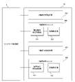
- FIG. 3 is a functional block diagram showing the internal configuration of the controller 4.
- the controller 4 includes a controller control unit 41, an analog stick 42, and a digital button unit 44.
- the controller 4 of the present embodiment will be described with an example of including only one analog stick 42, but in other embodiments, the controller 4 may be configured to include a plurality of analog sticks 42.
- the controller 4 also includes a battery and the like.
- the controller 4 may be provided with sensors such as an optical sensor and an inertial sensor.
- the controller control unit 41 is a circuit for controlling the controller 4, and includes a control microcomputer, a memory, a wireless module, an antenna, and the like.
- the controller control unit 41 controls a wireless module that wirelessly transmits transmission data to the information processing apparatus main body 2 while using the memory as a storage area during processing.
- data such as a preset library described later is also stored in the memory.
- the controller control unit 41 also controls the analog stick 42, which will be described later, according to the data from the information processing apparatus main body 2 received by the wireless module via the antenna.
- the analog stick 42 is an operator capable of inputting a direction. By tilting the analog stick 42, the user can input a direction according to the tilting direction (and input a size according to the tilting angle).
- the digital button unit 44 is one or more push-type buttons or trigger-type buttons.
- the analog stick 42 uses a magnetic viscous fluid (Magnetorheological fluid, hereinafter referred to as MRF).
- MRF Magnetic viscous fluid
- the MRF is a fluid when a magnetic field is not applied, and has the property of becoming semi-solid (generating viscosity) when a magnetic field is applied.
- the MRF also has the property of reacting to a magnetic field in a few ms.
- the viscosity of the MRF is controlled, and the MRF is caused to act on the movable axis of the analog stick 42 of the controller 4, and as a result, the ease of movement of the analog stick 42 is dynamically controlled.
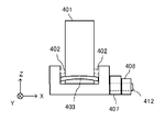
- FIG. 4 shows an example of the appearance of parts (hereinafter, stick devices) constituting the analog stick 42 assumed in the present embodiment.
- FIG. 4 is a perspective view of the stick device 400 constituting the analog stick 42.
- the stick device 400 includes a stick portion 401, an outer shell portion 404, an X-axis variable resistor 405, an X-axis MRF unit 406, a Y-axis variable resistor 407, and a Y-axis MRF unit 408.
- an X-axis drive component 402 is also provided so as to be adjacent to the stick portion 401.
- the stick device 400 also has a Y-axis return force adding portion 403, which will be described later.
- a stick portion 401 of the stick device 400 covered with a mushroom-shaped cover is used.
- the stick portion 401 is a rod-shaped movable part.
- the X-axis variable resistor 405 and the Y-axis variable resistor 407 are for detecting the inclination of the stick portion 401.
- the X-axis MRF unit 406 and the Y-axis MRF unit 408 are for causing the MRF to act on the movable axis of the analog stick 42 as described above.
- FIG. 5 shows a schematic diagram showing the positional relationship of each part when the stick device 400 is viewed from a bird's-eye view.
- FIGS. 6 and 7 show a schematic view (cross-sectional view) showing the positional relationship of each part when the stick device 400 is viewed from the side surface.
- FIG. 6 is a diagram assuming a case of being viewed from the left side in FIG. 5
- FIG. 7 is a diagram assuming a case of being viewed from the lower side of FIG.
- the stick portion 401 is arranged so that the center of the stick portion 401 is located at the center of the outer shell portion 404.
- the stick portion 401 is arranged so that the longitudinal direction is parallel to the Z axis.
- this center position is referred to as an initial position
- the posture in which the longitudinal direction of the stick portion 401 is parallel to the Z axis is referred to as an initial state.
- the X-axis drive component 402 and the Y-axis drive component 403 are provided adjacent to the stick portion 401.
- the X-axis drive component 402 moves the X-axis variable resistor 405 in conjunction with the movement of the stick portion 401 in the X-axis.
- the Y-axis drive component 403 moves the Y-axis variable resistor 407 in conjunction with the movement of the stick portion 401 on the Y-axis. Therefore, although not shown directly in these figures, the X-axis drive component 402 is coupled (inside the outer shell 404) to interlock with the X-axis variable resistor 405. Similarly, the Y-axis drive component is also connected so as to interlock with the Y-axis variable resistor 407.
- the circular opening also regulates the basic movable area of the stick portion 401 (analog stick 4).
- a regulation member having a similar function may be provided at the root portion of the stick portion 401.
- the housing of the controller 4 itself in the finished product of the controller 4 may be used as a regulating member. That is, in the housing, an opening having a predetermined shape may be provided at a position where the stick device 400 is attached so that the opening (shape) becomes the limit of the movable area of the analog stick 4.
- a return force adding section which is a mechanism for returning the stick section 401 to the initial position, is also provided below the stick section 401.
- the return force adding portion may be composed of a member or the like having an elastic body such as a coil spring inside and transmitting the return force to return to the initial position to return the stick portion 401 vertically.
- the larger the inclination of the stick portion 401 the greater the return force for returning to the initial position.
- the return force adding unit returns each of the above-mentioned drive parts interlocking with the stick unit 401 to the reference position.
- the mechanism for applying the restoring force is known, detailed description thereof will be omitted, but for example, the restoring force adding portion having the elastic body may be arranged so as to be perpendicular to the bottom surface of the outer shell portion 404. .. Then, a configuration is conceivable in which the drive body is kept in the reference state by directly or indirectly applying a force to the drive component.
- an example in which an elastic body is used is shown in this embodiment.
- a magnet may be used as long as it has the same function.
- a gear, a motor, or the like may be used in addition to or in place of the elastic body, the magnet, or the like.
- the stick device 400 is provided with a variable resistor 405 for the X-axis and a variable resistor 407 for the Y-axis so as to be adjacent to the outer shell portion 404. Since the variable resistor is a known technique, detailed description thereof will be omitted, but these are for detecting the inclination of the stick portion 401.
- Each variable resistor is provided with a rotating shaft connected to each of the driving components. The drive component rotates the rotating shaft in conjunction with the tilting / returning movement of the stick portion 401. Then, the resistance value corresponding to the rotation of the rotating shaft is detected.
- the processor 11 or the controller control unit 41 can determine the tilt angle and the like of the stick unit 401 in each of the X-axis and the Y-axis. That is, the direction in which the stick portion 401 is moving (hereinafter referred to as the displacement direction) and the inclination of the stick portion 401 (indicated position of the analog stick 42 on the XY plane: hereinafter simply referred to as “the position of the analog stick”) are calculated. It is possible to do.
- the displacement direction of the stick unit 401 is calculated by software by the processor 11 or the controller control unit 41, but the calculation subject is not limited to this.
- a configuration in which the displacement direction is mechanically detected by using a predetermined sensor may be adopted.
- the stick device 400 is provided with an X-axis MRF unit 406 so as to be adjacent to the outside of the X-axis variable resistor 405.
- the Y-axis MRF unit 408 is provided adjacent to the outside of the Y-axis variable resistor 407.
- the rotary shaft 411 used in the variable resistor 405 for the X axis is further extended outward, and the MRF unit 406 for the X axis is arranged so as to cover the rotary shaft 411.
- the rotary shaft 412 used in the Y-axis variable resistor 407 is also configured to extend further outward, and the Y-axis MRF unit 408 is arranged so as to cover the rotary shaft 412.
- the rotating shaft used in the variable resistor 405 for the X axis and the rotating shaft in the MRF unit may be connected so as to be interlocked with each other.
- the X-axis MRF unit 406 and the Y-axis MRF unit 408 may be collectively referred to as an MRF unit.
- FIG. 8 is a simplified schematic diagram for explaining a configuration example of the MRF unit.
- the rotation shaft 411 connected (or connected) to the variable resistor is arranged so as to pass through the MRF container 421 filled with the MRF.
- a magnetic field generating portion 422 is provided so as to cover the outside of the MRF container 421.
- the magnetic field generation unit 422 is, for example, a coil.
- the MRF unit is configured so that a current can flow through the magnetic field generating unit 422. A magnetic field can be generated by passing a predetermined amount of current through the magnetic field generating unit 422.
- By increasing the viscosity of the MRF it is possible to give resistance to the rotational force of the rotating shaft 411. Since the rotation shaft 411 is connected so as to be interlocked with the inclination of the stick portion 401 as described above, it is possible to give a resistance force to the force for tilting the stick portion 401 by the viscosity change of the MRF. That is, in the present embodiment, by controlling the viscosity of such an MRF, it is possible to control the ease of movement of the stick portion 401.
- FIG. 8 is a simplified drawing for convenience of explanation, a more specific configuration of the MRF unit will be supplemented.
- the basic mechanism is similar to that of a bicycle or automobile disc brake. In these disc brakes, the rotating wheel is directly sandwiched between mechanical parts and the rotation is stopped by the friction between the parts. However, when MRF is used as in this embodiment, the friction is controlled by controlling the viscosity of the fluid. Will be changed to regulate the movement in the direction of rotation.
- FIG. 9 is a functional block diagram showing the internal configuration of the analog stick 42.
- the analog stick 42 includes an X-axis variable resistor 405, an X-axis MRF unit 406, a Y-axis variable resistor 407, and a Y-axis MRF unit 408.
- Each of these components is electrically connected to the controller control unit 41, and can transmit and receive predetermined data.
- the controller control unit 41 can receive signals (for example, voltage values) from the variable resistor 405 for the X-axis and the variable resistor 407 for the Y-axis.
- the controller control unit 41 can calculate the position, displacement direction, and change speed (displacement speed) of the stick unit 401. Further, the controller control unit 41 can transmit the calculated result to the information processing apparatus main body 2.
- the position of the analog stick 42 is expressed as, for example, two-dimensional coordinates on a two-dimensional plane whose initial position (origin) is the center position. Further, the controller control unit 41 can transmit a signal for controlling the viscosity of the MRF unit to each MRF unit as described below based on the data transmitted from the information processing apparatus main body 2.
- the X-axis MRF unit 406 includes a voltage-current conversion circuit unit 431 and a magnetic field generation unit 422 as described above, both of which are electrically connected.
- a current based on the voltage can be output to the magnetic field generation unit 422.
- the viscosity of MRF can be changed as described above.
- the Y-axis MRF unit 408 also includes a voltage-current conversion circuit unit 431 and a magnetic field generation unit 422, and can be controlled in the same manner as described above.
- the X-axis and the Y-axis of the stick portion 401 can be individually affected by the change in the viscosity of the MRF.
- the ease of movement (viscosity) of the analog stick 42 is presented by the sum of the two axes of the X-axis and the Y-axis.
- the viscosity of the MRF of the Y-axis MRF unit 408 it is possible to create a state in which the stick portion 401 can be moved only in the X-axis direction.
- the viscosity of the MRF By controlling the viscosity of the MRF with the above configuration, in the present embodiment, it is possible to present various feelings to the user (finger) operating the analog stick 42. For example, by controlling the viscosity of the MRF according to a predetermined scene in the application, it is possible to give various feelings according to the scene to the fingertip of the user who operates the analog stick 42. Further, in the case of the controller 4 provided with a plurality of analog sticks 42, it is also possible to individually control the viscosity for each analog stick. This makes it possible to provide the user with a new feeling of operation that has never been seen before.
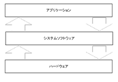
- FIG. 10 is a diagram for explaining the software hierarchy in the present embodiment.
- various applications can be executed. These applications basically have a software structure that operates (uses) on common system software.
- the system software is in charge of controlling various hardware constituting the information processing system 1.
- the hardware is, for example, the information processing apparatus main body 2 and the controller 4 including the MRF unit and the like.
- the parameters for controlling the above MRF will be described.
- the MRF control parameter is used, for example, as follows. First, the contents are set by the application, and this is transferred to the controller 4 via the system software. Then, there is a usage example in which the controller 4 controls the viscosity of the MRF based on the MRF control parameter.
- the viscosity parameter is a parameter that specifies three parameters of amplitude, frequency, and application time output from the controller control unit 41 to the voltage-current conversion circuit unit 431 (parameters P1 to P1 to be described later). Corresponds to P3).
- a voltage command value having a waveform having this parameter as a component is output to the voltage-current conversion circuit unit 431, and a current based on the voltage command value is output to the magnetic field generation unit 422.
- the resulting magnetic field can change the viscosity of the MRF.
- the range of motion information is information that defines the range of motion of the analog stick 42.
- the range of motion of the analog stick 42 is only in the Y-axis direction.
- the original range of motion hereinafter referred to as the basic range of motion
- this range of motion is to be limited only in the Y-axis direction as shown by the white portion in FIG.
- the content of the range of motion information is that the analog stick 42 tilts when the position of the analog stick 42 is within this area. It is a content that shows that there is no such thing.
- the specific data structure of the range of motion information is not limited to this, and any structure may be used as long as the range of motion can be defined.
- the range of motion (shape) of the analog stick 42 can be arbitrarily defined and treated as the range of motion information.
- the preset number is a number for designating a predefined preset.
- the preset is data in which what kind of viscosity parameter is set when the analog stick 42 is in which position (within the above basic movable range) is defined in advance. In other words, it is the data in which the viscosity parameter for each position in the basic movable range and the displacement speed of the analog stick 42 at that position is specified in advance.
- the controller control unit 41 As an example of the data structure, for example, it is conceivable to define presets in which viscosity parameters are set for each of a predetermined number of matrices as described above over the entire basic range of motion. Further, in the present embodiment, it is assumed that a plurality of presets are stored in advance as a "preset library" in the memory in the controller control unit 41. As an example of using the preset, an example in which the application transmits a predetermined preset number to the controller control unit 41 via the system software can be considered. In this case, the controller control unit 41 reads the corresponding preset number from the preset library. Further, the viscosity parameter is determined based on the content and the position and displacement speed of the analog stick 42 at that time. Then, the controller control unit 41 controls the MRF unit based on the viscosity parameter.
- the information to be held as a preset an example of having the position or displacement speed and the viscosity parameter associated with each other is given.
- the preset is not limited to such a data structure, and in other embodiments, for example, the data structure may have only a viscous parameter without information on the position and the displacement speed. That is, there may be a mode in which only some viscosity parameters are defined in advance and provided as a preset.
- the preset library may be configured to have a range of motion preset that defines only the range of motion and a preset that defines only the viscosity parameter as described above. For example, suppose you have a concentric range of motion preset. In this case, the viscosity of the MRF in the center circle and each ring surrounding the center circle may be quoted from a separately prepared viscosity parameter preset. This makes it possible to expand the range of expression using MRF, even though it has the appearance of a preset.
- the preset library stored in the controller control unit 41 may have an updatable configuration. For example, it may be configured to be updated periodically via the Internet. Alternatively, even if it is not connected to the Internet, it may be configured to be updatable via a predetermined storage medium. As an example, the memory card containing the update data may be read into the information processing apparatus main body 2 connected to the controller 4 and updated.
- the present embodiment mainly relates to the control of the controller 4 using the MRF unit, in other words, the control of the viscosity of the MRF.
- the control of the viscosity of the MRF As a place where this viscosity is independently controlled (designated / generated), in this embodiment, three patterns are assumed: an application, a system software, and a controller 4.
- three patterns can be used: mainly application-based control, system software-based control, and controller 4-based control.
- One of the reasons for assuming such a plurality of control patterns is the communication speed between the information processing device main body 2 and the controller 4, and the execution speed of the application executed in the information processing device main body 2. This is because the difference in response performance (in other words, the difference in response performance) is taken into consideration. These speeds may have a relationship of "communication speed between the analog stick 42 and the controller control unit 41> communication speed between the information processing device main body 2 and the controller control unit 41> application processing speed". In the present embodiment, for example, it is assumed that the communication speed between the analog stick 42 and the controller control unit 41 is 1 kHz, and the communication speed between the information processing apparatus main body 2 and the controller control unit 41 is 200 Hz. Further, regarding the processing speed of the application, it is assumed that the application operates at 60 Hz.
- the operation cycle on the controller side is faster than the operation cycle of the application. Therefore, when the application side mainly outputs the viscosity of the MRF, it is considered that the cycle in which the output reaches the controller control unit 41 is slower than the cycle in which the controller control unit 41 acquires the position of the analog stick 42. In this respect, especially when the control is performed so as to change the viscosity directly according to the position of the analog stick 42, the higher the responsiveness, the faster the change in viscosity can be realized and the range of expression of the feeling presentation is widened. it is conceivable that. For example, it is possible to suddenly change the feel and express the feel like an edge.
- control pattern A the control that the application outputs the viscosity parameter directly based on the execution state of the application will be described.
- the flow is shown in FIG. First, (A1) the controller control unit 41 receives a voltage value from the analog stick 42. Next, (A2) the controller control unit 41 calculates the position and displacement speed of the analog stick 42 based on this, and transfers it to the system software. Further, (A3) system software outputs the position and displacement speed of the analog stick 42 to the application. As a result, the application side can know the position and displacement speed of the analog stick 42.
- the application may be configured to generate and output a viscosity parameter, or may be configured to prepare a viscosity library in which a predetermined preset is stored on the application side. In the latter case, if the preset has a data structure that does not have information on the position or displacement speed of the analog stick but only has a viscous parameter, specify a predetermined preset number from this library and correspond to the preset number.
- the viscosity parameter to be used may be acquired and output.
- the preset has a data structure in which the data such as the application state and the viscosity parameter are associated with each other, the viscosity parameter may be acquired based on the preset number and the data such as the application state.
- the viscosity parameter is output based directly on the execution state of the application, but the viscosity parameter may be output directly based on the position of the analog stick.
- the position of the analog stick may be transmitted to the application side and the viscosity parameter may be generated based directly on the position of the analog stick. Then, the generated viscosity parameter may be output to the controller control unit 41.
- control uses the preset library stored in the controller control unit 41 as described above.
- this control is referred to as a control pattern B.
- the application specifies a predetermined preset number and transfers it to the system software.
- the system software transfers this preset number to the controller control unit 41.
- the controller control unit 41 calculates the position and displacement speed of the analog stick 42 based on the voltage value from the analog stick 42 at this time.
- the controller control unit 41 acquires the preset corresponding to the preset number from the preset library.
- the viscosity parameter is acquired based on the definition content of the preset and the calculated position and / or displacement speed of the analog stick 42. Then, the controller control unit 41 outputs the voltage command value based on the viscosity parameter to the MRF unit. In this way, the application simply specifies the preset number, and the viscosity control based on the corresponding preset is performed inside the controller 4.
- control pattern C As another example of the case where the controller 4 controls independently, the control as shown in FIG. 15 may be performed (hereinafter, this control is referred to as a control pattern C).
- This is intended for situations where the viscosity of the MRF is controlled independently of the application.
- the viscosity it is possible to set the viscosity to the user's preference.
- the user may specify an arbitrary viscosity from the "setting menu" of the information processing apparatus main body 2, and the specified contents may be stored as a preset. Then, the viscosity may be controlled according to the preset at all times or in an appropriate situation.
- FIG. 1 the control as shown in FIG.
- the system software transfers the stored preset number to the controller control unit 41.
- the controller control unit 41 calculates the position and displacement speed of the analog stick 42 based on the voltage value from the analog stick 42 at this time.
- the controller control unit 41 generates a viscosity parameter based on the preset number and the calculated position and displacement speed of the analog stick 42. Then, the controller control unit 41 outputs the voltage command value based on the viscosity parameter to the MRF unit. This allows the viscosity of the analog stick 42 to be controlled independently of the application.
- control may be performed without using the position or the like.
- the position (information indicating) of the analog stick 42 may not be used, and control may be performed so that the viscosity becomes uniformly predetermined over the entire movable range of the analog stick 42. That is, control may be performed so that a predetermined viscosity is always applied.
- control pattern D the system software controls independently
- the preset library is stored in the controller control unit 41, but in general, the storage capacity of the memory mounted in the controller control unit 41 is limited to some extent. Therefore, it is conceivable that the viscosity control pattern stored as the preset library is limited to some extent. Therefore, while ensuring a certain degree of responsiveness, it is also possible to use a pattern of controlling with system software in order to enable more expressions than those of the preset library as an expression of the feel by viscosity control. As an example of the control flow in this case, the flow as shown in FIG. 16 can be considered.
- the above-mentioned range of motion information is transferred from the application to the system software.
- the controller control unit 41 receives a voltage value from the analog stick 42.
- the controller control unit 41 calculates the position and displacement speed of the analog stick 42 based on this, and transfers it to the system software.
- the system software generates the viscous parameter based on the movable range information and the position and displacement speed of the analog stick 42, and transfers the viscous parameter to the controller control unit 41.
- the controller control unit 41 outputs the voltage command value based on the viscosity parameter to the MRF unit. In other words, it can be said that the flow of FIGS. 16 (D2) to (D5) is looped, and the application sends range of motion information to this loop at an arbitrary timing.
- control patterns are examples, and other control methods can be used depending on the use case of the application.
- the viscosity of the analog stick 42 is increased according to the position of the virtual object in the virtual space.
- the virtual object can be moved based on the position of the analog stick 42, but the viscosity is not controlled directly based on the position of the analog stick 42.
- the viscosity is controlled based directly on the position of the virtual object in the virtual space, in other words, the execution state of the application. Therefore, in such a case, the application side takes the initiative in the viscosity parameter.
- the viscosity parameter may be generated in the code of the application, or the preset of the viscosity parameter may be provided as a library in the application of the latter. In that case, for example, a preset corresponding to the terrain in the virtual space may be prepared and a predetermined preset may be specified based on the position of the virtual object. In this way, the application side independently prepares the viscosity parameter and outputs it. When doing so, the range of expression of the feeling given to the user can be expanded.
- the controller control unit 41 is the main body. It becomes possible to control the viscosity.
- the MRF acts like a brake, and as a result, the analog stick 42 remains tilted and does not return to the initial position, or It is possible that it will be very late even if it returns. Therefore, there is a possibility that the operation feeling that the user would expect from the analog stick 42 cannot be provided.
- the control of the current applied to the MRF is controlled as described below in order to achieve both the presentation of the feel using the MRF and the initial position return operation.
- FIG. 17 is a timing chart for explaining the control in the first embodiment.
- the vertical axis represents the amplitude (current amount) and the horizontal axis represents time.
- P1 indicates an amplitude and P2 indicates a period (frequency).
- P3 indicates a time for passing a current in one cycle (in other words, a time for applying a voltage, hereinafter referred to as an application time).
- the period P2 and the application time P3 can be controlled in units of 1 millisecond.
- the amplitude P1, the period P2, and the application time P3 correspond to the above-mentioned "viscosity parameter".
- the application time P3 may be controlled by designating the duty ratio (Duty) in addition to the control of designating the time. That is, by controlling the duty ratio as a parameter, the application time may be controlled as a result. In this case as well, it can be said that the application time is controlled. The same applies to other parameters, and if the target parameter is controlled as a result, various parameters used in the specific method and calculation may be appropriately adopted.
- the value of the amplitude P1 is such that the viscosity of the MRF becomes larger than the return force by the return force addition portion. That is, it is assumed that the value remains tilted even when the finger is released from the analog stick 42.
- the current having the strength indicated by P1 is first passed for the time indicated by the applied time P3, and the current is not passed thereafter.
- the viscosity of the MRF becomes a state in which the analog stick 42 does not autonomously return to the initial position even when the finger is released (hereinafter, referred to as a highly viscous state).
- the term "does not return to the initial position" here basically means a state in which the analog stick 42 does not move even if the finger is separated from the analog stick 42.
- the present invention is not limited to this, and in another embodiment, the highly viscous state may be a state in which the moving speed is very slow although the moving autonomously toward the initial position. For example, when it is not in a highly viscous state, it returns to the initial position within 1 second after releasing the finger, but in the case of a highly viscous state, the movement speed is slow, so it takes 5 seconds to return to the initial position. , Or it may take 10 seconds.
- the viscosity of the MRF also decreases in order to prevent the voltage from being applied (current does not flow), the recovery force exceeds the resistance due to the viscosity of the MRF, and the analog stick is autonomously initially initialized. It is in a state where it can return to the position (hereinafter, this state is referred to as a low viscosity state).
- this state is referred to as a low viscosity state.
- the period of the low viscosity state is set to a length equal to or longer than a predetermined period so as to guarantee the substantial start of the return operation.
- the above example illustrates the case where no voltage is applied, but in other examples, the analog stick 42 does not interfere with the initial position return operation even during the period of the low viscosity state.
- the voltage of may be applied.
- the specific values of the viscosity parameters for realizing the high viscosity state and the low viscosity state may be stored in the controller control unit 41 as presets as described above.
- the configuration is not limited to the configuration stored in the controller control unit 41, and a configuration in which such a preset is provided by the system software may be used.
- such a preset may be defined on the application side and may be configured to be included as a part of the application program.
- the application outputs the amplitude P1 and the period P2 to the system software as viscosity information.
- the system software calculates the application time P3 based on the amplitude P1 and the period P2. In this calculation, the system software applies the application time so that the amplitude P1 and the period P2 correspond to the high-viscosity state, while the period during which the analog stick 42 can return to the initial position (the low-viscosity state) can be secured. Calculate P3.
- the system software is configured to have data in which the amplitude P1 and the period P2 are associated with the values of the appropriate application time P3 corresponding thereto. Then, when the viscosity information is received from the application, the appropriate application time P3 is determined with reference to the data.
- a predetermined algorithm may be used for calculation. Then, the system software outputs the determined application time P3, the amplitude P1 and the period P2 from the application as the viscosity parameters to the controller control unit 41. With such control, it is possible to reduce the data size and the storage capacity as compared with the case where all three components constituting the viscosity parameter are stored as presets.
- a control of adjusting the viscosity of the MRF (correcting the viscosity parameter) according to the return force by the return force addition unit will be described. This takes into consideration the difference in the return force due to the individual difference of the controller 4. More specifically, in this control, a return force parameter indicating the strength and performance of the return force is acquired by a predetermined method. Then, it is assumed that the content of the viscosity parameter is corrected according to the return force parameter. When performing such control, it is first necessary to acquire the return force parameter. The following can be considered as a method for acquiring this return force parameter. First, it is conceivable to provide the controller 4 or the like with a sensor that directly measures the return force.
- the user is made to tilt the analog stick 42 to the movable limit position, for example, to the full right end and then release the finger, and after releasing the finger, until returning to the initial position.
- a method of measuring the return time is also conceivable. In this case, this return time may be used as it is as the return force parameter, or the return force parameter may be calculated separately based on the return time.
- the torque of the coil spring corresponding to the position of the analog stick 42 may be used as the return force parameter.
- the torque of the coil spring corresponding to the current position of the analog stick 42 may be calculated by a predetermined method, and control may be performed to correct the content of the viscosity parameter by using this as a recovery force parameter.
- control may be performed using the position of the analog stick 42. That is, the content of the viscosity parameter that realizes the high viscosity state or the low viscosity state may be adjusted according to the position of the analog stick 42. Further, control may be performed to change the period of the high viscosity state or the low viscosity state according to the position of the analog stick 42.
- At least one of the following controls may be performed as compared with the case where the return force is large.
- the control is performed to make it easier to return to the initial position. For example, control is assumed in which the viscosity in a highly viscous state is lowered as the restoring force becomes smaller.
- the return force indicated by the return force parameter is smaller than a predetermined reference value, it is determined that the return force is weakened, and control is performed to facilitate the return to the initial position. May be good.
- the viscosity parameter is passed from the application or system software to the controller control unit 41.
- the controller control unit 41 corrects the amplitude P1 and / or the application time P3 for this viscosity parameter according to the return force parameter.
- the viscosity is controlled using the corrected viscosity parameter.
- the controller control unit 41 can also correct the period P2.
- the viscosity is adjusted by changing the amplitude P1 or the application time P3, assuming that the period P2 is constant. It should be noted that the "constant" of the cycle does not have to be constant in a strict sense, and the cycle may have a slight fluctuation or fluctuation range as long as it can be said to be substantially constant.
- the amplitude P1 is increased and the application time P3 is controlled to be constant or decrease.
- the viscosity is increased by increasing the amplitude P1 instead of the application time P3.
- the application time P3 may not be changed (remains constant), or may be decreased to secure a longer period of the low viscosity state.
- the controller control unit 41 As the main body that adjusts the viscosity parameter according to the return force, the one assuming the controller control unit 41 is exemplified, but in other embodiments, the same processing is performed on the system software or the application side. You may.
- the high-viscosity state and the low-viscosity state are periodically and alternately changed.
- both the feeling presentation using the high viscosity state and the initial position return operation using the low viscosity state are achieved.
- the embodiment is mainly an example of control in consideration of the relationship between the displacement direction of the analog stick 42 and the return force by the return force addition unit. More specifically, it is an example of performing control so as to keep the resistance felt by the user at the fingertip constant regardless of the displacement direction of the analog stick 42.
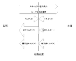
- FIG. 18 is a schematic diagram showing a locus when the analog stick 42 is displaced from the left end to the right end within the movable range. Further, FIG. 19 is a diagram schematically showing what the corrected torque will be when the control in the present embodiment described later is not performed. Further, FIG. 20 is a diagram schematically showing what the corrected torque will be when the control in the present embodiment is performed.
- the "displacement of the stick position” indicates the displacement of the position of the analog stick
- the "movement of the user's finger” indicates the actual movement of the user's finger.
- Torque is shown as an example of the return force, and is, for example, a constant generated by a spring or the like as described above.
- MRF torque indicates the resistance force due to MRF.
- corrected torque indicates a value obtained by correcting the above “torque” (due to a spring or the like) by the above “MRF torque”.
- FIG. 19 will be described.
- the displacement direction of the analog stick 42 (and the user's finger) is to the right. Therefore, the MRF torque basically becomes a resistance force toward the left.
- the torque becomes a rightward force from the left end to the initial position, and the torque becomes a leftward force from the initial position to the right end.
- the viscosity of the MRF does not change (is constant) until the position of the analog stick 42 moves from the left end to the right end. In this case, if the corrected value is not adjusted by the MRF torque, the corrected torque amount may change significantly.
- FIG. 19 the displacement direction of the analog stick 42 (and the user's finger) is to the right. Therefore, the MRF torque basically becomes a resistance force toward the left.
- the torque becomes a rightward force from the left end to the initial position
- the torque becomes a leftward force from the initial position to the right end.
- the viscosity of the MRF does not change (is constant) until the position of the analog stick 42 moves from the left
- the torque of the force of "3" facing to the right is offset by the MRF torque of the force of "1" facing to the left from the left end to the initial position, and the corrected torque. Turns to the left and becomes a force of "1".
- the MRF torque of the same force of "2” is added to the torque of the force of "3" in the left direction, and the corrected torque is the same in the left direction, but “ It becomes the power of "5".
- the force will change significantly (although there is no change in orientation) with the initial position as the boundary.
- the displacement direction of the analog stick 42 when the displacement direction of the analog stick 42 is a direction approaching the initial position, the displacement direction of the analog stick 42 is a direction away from the initial position. Control is performed so that the viscosity becomes larger than that. That is, the viscosity of the MRF is controlled so that the relationship "viscosity at the time of displacement toward the initial position> viscosity at the time of displacement away from the initial position" is satisfied.
- the value of the MRF torque in the former case is "7", and the value in the latter case is exemplified as "1".
- the corrected torque can be a force of "4" both when approaching the initial position and when moving away from the initial position, and it is possible to prevent the corrected torque from changing significantly. ..
- the corrected torque can be made (almost) constant regardless of the displacement direction of the analog stick 42. In the example of FIG. 20, even when the analog stick 42 is displaced straight from the left end to the right end, a substantially constant torque can be presented as the torque felt by the user's finger during this period.
- the analog stick 42 used in the second embodiment has a configuration in which the X-axis and the Y-axis have separate MRF units. Therefore, it is possible to separately control the viscosity of the X-axis and the Y-axis to generate a certain torque.
- the torque (viscosity) of the analog stick 42 is basically presented to the user as the sum of the viscosities of the X-axis and the Y-axis. At this time, if the torque calculated for each axis is used as it is and added up, the torque may be too strong.
- the torque in each direction of the X-axis and the Y-axis is calculated in consideration of the moving direction of the analog stick 42.
- the analog stick 42 is moving in a direction of 45 degrees diagonally upward to the right.
- the target (torque) force multiplied by 1 / ⁇ 2 is output to each of the X-axis and Y-axis.
- the torque is calculated separately for the X-axis and the Y-axis, and in another embodiment, if the above MRF unit (corresponding element) is only one. In that case, the above control is not always necessary.
- the control is also performed from the following viewpoints.
- the return force addition portion is an elastic body, it is considered that the return force increases as it is far from the initial position and decreases as it is closer to the initial position. Therefore, in the second embodiment, in addition to the above control, the MRF is controlled so that the viscosity of the MRF becomes larger when the distance from the initial position is short than when the distance is short. Considering the distance from the initial position, the magnitude of the viscosity of the MRF is indicated by the thickness of the arrow of the MRF torque, and the relationship is as shown in FIG. 21.
- a software-like method in which the controller control unit 41 calculates the displacement direction by comparing the change between the current position of the analog stick and the position detected immediately before is used. You may use it. Further, a hardware-like method may be used in which a predetermined sensor such as a pressure-sensitive sensor whose displacement direction can be detected is further mounted on the controller 4 and the detection result is used.
- the amplitude P1 and / or the application time P3 shall be corrected. That is, as in the first embodiment, the viscosity is adjusted by changing the amplitude P1 or the application time P3 while keeping the period P2 constant. This is because, as described above, when the period P2 is changed to change the viscosity, the change in the feel given to the user may become too large.
- the control shown in the second embodiment is basically mainly controlled by the controller 4. That is, in the control patterns B or C as shown in FIGS. 14 to 15, the controller control unit 41 detects the displacement direction of the stick unit 401 ((B3) in FIG. 14 and (C2) in FIG. 15). Then, the controller control unit 41 controls the viscosity of the MRF by correcting the viscosity parameter transferred from the application or the system software so that a constant sense of torque can be obtained based on the detected direction (the viscosity of the MRF is controlled by the controller control unit 41. 14 (B4), 15 (C3)). It should be noted that the reason why the controller 4 is the main control body is that when the viscosity control in consideration of the displacement direction is performed, higher responsiveness is required from the viewpoint of the difference in processing speed as described above. Because.
- the preset library is stored in the controller control unit 41. Therefore, when viewed from the application or system software side, in addition to directly specifying the viscosity parameter, it is also possible to specify the preset number registered in the preset library and transfer it to the controller control unit 41. Is. In this case, the controller control unit 41 reads the viscosity parameter corresponding to the designated preset number from the preset library, and corrects the viscosity parameter according to the displacement direction and the return force as described above. Then, the viscosity of the MRF is controlled by using the corrected viscosity parameter.
- the control is performed in consideration of the relationship between the displacement direction of the analog stick 42 and the return force by the return force addition portion. As a result, it is possible to suppress variations in the resistance force felt by the user regardless of the displacement direction of the analog stick 42, and to make the torque felt by the user substantially constant.
- the above MRF may be applied to an input device capable of changing the direction in three axes (three dimensions) of XYZ, and control as shown in the first embodiment may be performed.
- an example is described assuming a state in which the analog stick 42 does not substantially autonomously return to the initial position even if the finger is released as a highly viscous state.
- a state in which a larger current than in the low viscosity state may be applied may be applied regardless of whether or not the initial position is autonomously restored.
- an autonomous initial position return operation may be performed in either a high viscosity state or a low viscosity state, but there may be a difference in the speed of returning to the initial position. That is, the initial position return speed is faster in the low viscosity state than in the high viscosity state.
- the position of the above-mentioned MRF unit is an example, and is not limited to the above-mentioned one.
- a configuration may be adopted in which the stick portion 401 is in direct contact with the MRF, or any other position may be provided as long as it can affect the ease of movement of the stick portion 401.
- the system software or the controller control unit may finally correct the specified viscosity parameter according to the type of the controller and the preference of the user. For example, a control may be performed in which a correction for multiplying a specified viscosity parameter (one component thereof, for example, an amplitude) by 1.2 times is performed. Such a correction magnification may be calculated or preset based on the controller type. Alternatively, it may be determined based on the content specified by the user.
- control of MRF an example of control in which two viscous states, a high-viscosity state and a low-viscosity state, are periodically and alternately changed is given.
- control using three or more viscous states may be performed.
- control may be performed so that the states A, B, and C having different viscosities change periodically in a predetermined order.
- an information processing system in which the information processing device main body 2, the monitor 3, and the controller 4 are configured separately is illustrated, but in addition, the information processing device main body, a predetermined display unit, an analog stick, and a button are used.
- the above configuration and control can be applied to a portable information processing device or the like integrated with the above.
- the information processing system can provide a new operation feeling to the user, and is useful for applications such as a controller used in various information processing devices such as a personal computer.
- Information processing system 2 Monitor 3 Information processing device main body 4 Controller 11 Processor 12 Storage unit 13 Controller communication unit 14 Video / audio output unit 41 Controller control unit 42 Analog stick 44 Digital button unit 401 Stick unit 402 X-axis drive component 403 Y-axis Drive parts 404 Outer part 405 Variable resistor for X-axis 406 MRF unit for X-axis 407 Variable resistor for Y-axis 408 MRF unit for Y-axis
Abstract
Description
上記回路は、振幅、周波数、印加時間のうち、周波数は変化させずに、振幅および/または印加時間を変化させることで、粘性を変化させてもよい。
まず、アプリケーションが主体的に制御する場合(以下、制御パターンAと呼ぶ)について説明する。ここでは一例として、アプリケーションが、アプリケーションの実行状態に直接的に基づいて粘性パラメータを出力するという制御を説明する。この場合の制御の流れの一例としては、図13で示す流れとなる。まず、(A1)コントローラ制御部41はアナログスティック42から電圧値を受け取る。次に、(A2)コントローラ制御部41は、これに基づきアナログスティック42の位置や変位速度を算出し、システムソフトウェアに転送する。更に、(A3)システムソフトウェアは、このアナログスティック42の位置や変位速度をアプリケーションに出力する。これにより、アプリケーション側では、アナログスティック42の位置や変位速度を知ることができる。次に、(A4)アプリケーション側において、上記システムソフトウェアから出力されたアナログスティック42の位置や変位速度を反映したアプリケーション処理を行い、その結果を踏まえたアプリケーションの実行状態に基づいて、上記粘性パラメータを生成してシステムソフトウェアに転送する。このアプリケーションの実行状態とは、例えば、仮想空間内における仮想オブジェクトの位置や、当該仮想オブジェクトの状態、アプリケーションの進行状況が所定の場面であるか、等である。次に、(A5)システムソフトウェアは、当該粘性パラメータをコントローラ制御部41に転送する。そして、(A6)コントローラ制御部41は、当該粘性パラメータに基づく電圧指令値をMRFユニット出力する。このように、当該制御パターンでは、アプリケーションの状態に直接的に基づき、アプリケーションが粘性制御パラメータを主体的に出力する制御となっている。
次に、コントローラ4が主体的に制御する場合について説明する。本実施例では、一例として、、上述したようなコントローラ制御部41に記憶されているプリセットライブラリを利用する制御となっている。制御の流れの一例としては、図14に示すような制御の流れがある(以下、この制御のことを制御パターンBと呼ぶ)。まず、(B1)アプリケーションは、所定のプリセット番号を指定してシステムソフトウェアに転送する。(B2)システムソフトウェアは、このプリセット番号をコントローラ制御部41に転送する。(B3)コントローラ制御部41は、この時点におけるアナログスティック42からの電圧値に基づき、アナログスティック42の位置や変位速度を算出する。(B4)次に、コントローラ制御部41は、上記プリセット番号に対応するプリセットをプリセットライブラリから取得する。そして、当該プリセットの定義内容と当該算出したアナログスティック42の位置および/または変位速度とに基づいて、粘性パラメータを取得する。そして、コントローラ制御部41は、当該粘性パラメータに基づく電圧指令値をMRFユニットに出力する。このように、アプリケーションからはプリセット番号を指定するだけで、コントローラ4内部で対応するプリセットに基づく粘性制御が行われる。
次に、システムソフトウェアが主体的に制御する場合(以下、制御パターンDと呼ぶ)について説明する。上記のように、本実施形態ではコントローラ制御部41にプリセットライブラリを記憶する構成であるが、一般に、コントローラ制御部41に搭載されるメモリの記憶容量はある程度限られた容量である。そのため、プリセットライブラリとして記憶される粘性制御のパターンもある程度限られたものとなってしまうことも考えられる。そのため、ある程度の応答性を確保しつつも、粘性制御による感触の表現として、プリセットライブラリのものより多くの表現を可能とするために、システムソフトウェアで制御するというパターンも利用可能としている。この場合の制御の流れの一例としては、図16のような流れが考えられる。まず、(D1)アプリケーションからシステムソフトウェアに、上述した可動域情報を転送する。(D2)コントローラ制御部41はアナログスティック42から電圧値を受け取る。(D3)更に、コントローラ制御部41は、これに基づきアナログスティック42の位置や変位速度を算出し、システムソフトウェアに転送する。(D4)システムソフトウェアは、上記可動域情報とアナログスティック42の位置や変位速度に基づき、上記粘性パラメータを生成してコントローラ制御部41に転送する。(D5)そして、コントローラ制御部41は、当該粘性パラメータに基づく電圧指令値をMRFユニット出力する。換言すれば、図16の(D2)~(D5)の流れがループしており、このループに対してアプリケーションが可動域情報を任意のタイミングで送り込む、というような流れであるとも言える。
上記のような制御パターンの使い分けの一例として、「アナログスティック42の位置に直接的に応じた粘性制御」と、「アナログスティック42の位置に直接的には応じないの粘性制御」とを使い分ける例を説明する。これは、アナログスティック42の位置に直接的に応じた粘性制御をするか否かによって、より適切な制御を用いるというものである。例えば、仮想空間内で仮想オブジェクトを移動させることが可能なアプリケーションを想定する。このようなアプリケーションにおいて、仮想オブジェクトを移動させるにあたって、仮想空間内における当該仮想オブジェクトの場所に応じて上記粘性が変化する、という制御を行うことができる。この制御は、上記のアナログスティック42の位置に直接的には応じない粘性制御となる。一例を挙げると、アナログスティック42で仮想オブジェクトを操作できるアプリケーションにおいて、仮想オブジェクトの仮想空間内の位置に応じてアナログスティック42の粘性を高める、という場合が考えられる。この場合は、アナログスティック42の位置に基づいて仮想オブジェクトを移動できるものであるが、しかし、このアナログスティック42の位置に直接的に基づいて粘性を制御するものではない。あくまで、「仮想空間内の仮想オブジェクトの位置、換言すれば、アプリケーションの実行状態に直接的に基づいて粘性を制御するということになる。そのため、このような場合は、アプリケーション側が主体的に粘性パラメータを出力する制御を行う。この粘性パラメータの取得・出力手法については、アプリケーションのコード内で粘性パラメータを生成してもよいし、粘性パラメータのプリセットをアプリケーション内においてライブラリとして備える構成でもよい。後者の場合は、例えば仮想空間内の地形に応じたプリセットを用意して、仮想オブジェクトの位置に基づいて所定のプリセットを指定すればよい。このように、アプリケーション側が主体的に粘性パラメータを用意して出力する場合、ユーザに与える感触の表現の幅を広げることができる。
まず、本実施形態における第1の実施例について説明する。当該実施例は、上記MRFを用いるアナログスティックの制御において、「様々な感触の提示」と「アナログスティックに指が触れていない際の初期位置復帰」とを両立させることを主眼とした制御の例である。
まず、第1の実施例における制御の原理について説明する。一般的に、ユーザが求めるであろうアナログスティック42の操作感として、アナログスティック42から手や指を離したときには、アナログスティック42の位置が初期位置(初期状態)に復帰して欲しい、という操作感が考えられる。この点、上述のようなMRFをアナログスティック42に用いた場合、MRFの粘性を高めることで、ユーザに様々な感触を提示できる。その反面、粘性がある程度高い状態の場合、アナログスティック42から手や指を離したときでも、MRFがブレーキのような役割を果たす結果、アナログスティック42が傾いたまま初期位置に戻らない、あるいは、戻るとしても非常に遅くなる、ということが考えられる。そのため、ユーザがアナログスティック42に求めるであろう操作感が提供できない可能性がある。この点に関し、その解決策として、MRFによる抵抗力を小さくするか、あるいは復帰力自体を大きくすることが考えられる。しかし、抵抗力を小さくすると、当該抵抗力によって実現可能なユーザ体験やアプリケーションにおける表現が制約されることになってしまう。そこで第1の実施例では、上記MRFに与える電流の制御について以下に説明するような制御を行うことで、MRFを利用した感触の提示と初期位置復帰動作との両立を図っている。
(1)高粘性状態における粘性を低くする制御
(2)高粘性状態である期間を短くする制御
(3)低粘性状態における粘性を低くする制御(低粘性状態でもある程度電圧かけている場合を想定)
(4)低粘性状態である期間がより長くなるようにする制御
いずれの制御も、復帰力が小さい場合、初期位置に戻りやすくする制御を行うものとなっている。例えば、復帰力が小さくなるほど高粘性状態における粘性を低くする制御等が想定される。
次に、第2の実施例について説明する。当該実施例は、主に、アナログスティック42の変位方向と、上記復帰力付加部による復帰力との関係を考慮した制御の例である。より具体的には、アナログスティック42の変位方向に関わらず、ユーザが指先に感じる抵抗感を一定にするような制御を行う例である。
なお、上記第1の実施例に関して、X軸とY軸の2軸(2次元)の方向変化が検出可能なアナログスティック42にMRFを適用する例を挙げたが、この他、同じく2次元の方向変化が検出可能なスライドスティックに上記構成を適用することも可能である。また、他の実施例では、このような2軸の入力が可能なデバイスに限らず、1軸(1次元)での方向変化が可能な入力デバイスに上記のような構成を適用してもよい。例えば、所定の1軸周りに回転するダイヤル式の操作子に上記のようなMRFユニットに相当する要素を適用してもよい。この場合は、粘性変化により回転のしやすさについて影響を与えつつ、初期位置への復帰も実現することができる。あるいは、上記デジタルボタン部44のような押下式のボタン(これは、上下方向にのみ移動可能であるといえる)に適用してもよい。あるいは、トリガー式のボタンに適用してもよい。この場合は、ボタンの押しやすさ(押圧に対する抵抗感)について、MRFの粘性による影響を与えることができる。
2 モニタ
3 情報処理装置本体
4 コントローラ
11 プロセッサ
12 記憶部
13 コントローラ通信部
14 映像音声出力部
41 コントローラ制御部
42 アナログスティック
44 デジタルボタン部
401 スティック部
402 X軸用駆動部品
403 Y軸用駆動部品
404 外郭部
405 X軸用可変抵抗器
406 X軸用MRFユニット
407 Y軸用可変抵抗器
408 Y軸用MRFユニット
Claims (11)
- ユーザ操作によって初期位置から変位されるスティックと、
前記変位したスティックの位置を前記初期位置に戻す復帰力を加える復帰力付加部と、
磁場の強度に応じて粘性が変化し、前記スティックが前記初期位置から、および、前記初期位置へ変位する際の抵抗となる磁気粘性流体を用いた抵抗部と、
前記磁気粘性流体に対して磁場を与える磁場発生部とを備えるコントローラと、
前記磁場発生部を制御可能な回路と、を備える情報処理システムであって、
前記回路は、前記スティックの変位方向が前記初期位置に近づいていく方向である場合は、当該変位方向が当該初期位置から離れていく方向である場合よりも前記粘性が大きくなるように前記磁場の強度を変化させる、情報処理システム。 - 前記回路は、
前記磁場に印加する電流の振幅、周波数、印加時間を制御することで前記磁気粘性流体の粘性を変化させ、
前記変位方向が前記初期位置に近づいていく方向である場合は、当該初期位置から離れていく方向である場合よりも前記振幅または印加時間を大きくする、請求項1に記載の情報処理システム。 - 前記復帰力付加手段は、前記スティックの位置が前記初期位置から遠いほど復帰力が大きくなるよう構成されており、
前記回路は、前記スティックの変位方向が前記初期位置から離れていく方向である場合、当該スティックの位置が当該初期位置から遠くなるほど前記振幅または印加時間を小さくする、請求項2に記載の情報処理システム。 - 前記回路は、前記振幅、周波数、印加時間のうち、周波数は変化させずに、振幅および/または印加時間を変化させることで、前記粘性を変化させる、請求項2または3に記載の情報処理システム。
- 前記回路は、前記振幅については大きくし、前記印加時間については一定のままとするあるいは減少させることで、前記粘性が大きくなるように変化させる、請求項4に記載の情報処理システム。
- 前記コントローラは、
前記スティックの変位方向を検出する方向検出部を更に備え、
前記方向検出部によって検出された前記変位方向に基づいて前記磁場の強度を変化させる、請求項1乃至5のいずれかに記載の情報処理システム。 - 前記コントローラは、前記情報処理システムを制御するためのシステムソフトウェアまたは当該情報処理システム上で動作する所定のアプリケーションから出力された情報であって、前記磁気粘性流体の粘性の状態を指定する情報である粘性指定情報を前記検出方向に基づいて補正し、当該補正後の粘性指定情報に基づいて前記磁場の強度を変化させる、請求項6に記載の情報処理システム。
- 前記コントローラは、
所定の粘性状態が実現される粘性を示す情報がプリセットとして複数含まれ得るプリセットライブラリを記憶するライブラリ記憶部を更に含み、
前記情報処理システムを制御するためのシステムソフトウェアまたは当該情報処理システム上で動作する所定のアプリケーションから出力された前記プリセットのいずれかを指定する情報に基づいて、当該指定されたプリセットに対応した所定の粘性を示す情報を前記プリセットライブラリから取得し、当該取得した情報を前記検出方向に基づいて補正し、当該補正後の粘性指定情報に基づいて前記磁場の強度を変化させる、請求項6に記載の情報処理システム。 - ユーザ操作によって初期位置から変位されるスティックと、
前記変位したスティックの位置を前記初期位置に戻す復帰力を加える復帰力付加部と、
磁場の強度に応じて粘性が変化し、前記スティックが前記初期位置から、および、前記初期位置へ変位する際の抵抗となる磁気粘性流体を用いた抵抗部と、
磁気粘性流体に対して磁場を与える磁場発生部と、
磁場発生部を制御可能な回路とを備えるコントローラであって、
前記回路は、前記スティックの変位方向が前記初期位置に近づいていく方向である場合は、当該変位方向が当該初期位置から離れていく方向である場合よりも前記粘性が大きくなるように前記磁場の強度を変化させる、コントローラ。 - ユーザ操作によって初期位置から変位されるスティックと、
前記変位したスティックの位置を前記初期位置に戻す復帰力を加える復帰力付加部と、
磁場の強度に応じて粘性が変化し、前記スティックが前記初期位置から、および、前記初期位置へ変位する際の抵抗となる磁気粘性流体を用いた抵抗部と、
磁気粘性流体に対して磁場を与える磁場発生部とを備えるコントローラと、
磁場発生部を制御可能な回路と、を備える情報処理システムを制御する情報処理制御方法であって、
前記回路に、前記スティックの変位方向が前記初期位置に近づいていく方向である場合は、当該変位方向が当該初期位置から離れていく方向である場合よりも前記粘性が大きくなるように前記磁場の強度を変化させる、情報処理方法。 - ユーザ操作によって初期位置から変位されるスティックと、
前記変位したスティックの位置を前記初期位置に戻す復帰力を加える復帰力付加部と、
磁場の強度に応じて粘性が変化し、前記スティックが前記初期位置から、および、前記初期位置へ変位する際の抵抗となる磁気粘性流体を用いた抵抗部と、
前記磁気粘性流体に対して磁場を与える磁場発生部と
を備えるコントローラと、
磁場発生部を制御可能な回路と、を備える情報処理システムのコンピュータに実行させる情報処理プログラムであって、
前記コンピュータに、前記スティックの変位方向が前記初期位置に近づいていく方向である場合は、当該変位方向が当該初期位置から離れていく方向である場合よりも前記粘性が大きくなるように前記磁場の強度を変化させる、情報処理プログラム。
Priority Applications (5)
| Application Number | Priority Date | Filing Date | Title |
|---|---|---|---|
| JP2022563319A JPWO2022107259A1 (ja) | 2020-11-18 | 2020-11-18 | |
| EP20962423.8A EP4227770A1 (en) | 2020-11-18 | 2020-11-18 | Information processing system, controller, information processing method, and information processing program |
| PCT/JP2020/043072 WO2022107259A1 (ja) | 2020-11-18 | 2020-11-18 | 情報処理システム、コントローラ、情報処理方法、情報処理プログラム |
| CN202080107182.6A CN116529696A (zh) | 2020-11-18 | 2020-11-18 | 信息处理系统、控制器、信息处理方法、信息处理程序 |
| US18/316,008 US20230280848A1 (en) | 2020-11-18 | 2023-05-11 | Information processing system, controller, information processing method, and computer-readable non-transitory storage medium having stored therein information processing program |
Applications Claiming Priority (1)
| Application Number | Priority Date | Filing Date | Title |
|---|---|---|---|
| PCT/JP2020/043072 WO2022107259A1 (ja) | 2020-11-18 | 2020-11-18 | 情報処理システム、コントローラ、情報処理方法、情報処理プログラム |
Related Child Applications (1)
| Application Number | Title | Priority Date | Filing Date |
|---|---|---|---|
| US18/316,008 Continuation US20230280848A1 (en) | 2020-11-18 | 2023-05-11 | Information processing system, controller, information processing method, and computer-readable non-transitory storage medium having stored therein information processing program |
Publications (1)
| Publication Number | Publication Date |
|---|---|
| WO2022107259A1 true WO2022107259A1 (ja) | 2022-05-27 |
Family
ID=81708610
Family Applications (1)
| Application Number | Title | Priority Date | Filing Date |
|---|---|---|---|
| PCT/JP2020/043072 WO2022107259A1 (ja) | 2020-11-18 | 2020-11-18 | 情報処理システム、コントローラ、情報処理方法、情報処理プログラム |
Country Status (5)
| Country | Link |
|---|---|
| US (1) | US20230280848A1 (ja) |
| EP (1) | EP4227770A1 (ja) |
| JP (1) | JPWO2022107259A1 (ja) |
| CN (1) | CN116529696A (ja) |
| WO (1) | WO2022107259A1 (ja) |
Families Citing this family (1)
| Publication number | Priority date | Publication date | Assignee | Title |
|---|---|---|---|---|
| WO2022107258A1 (ja) * | 2020-11-18 | 2022-05-27 | 任天堂株式会社 | 情報処理システム、コントローラ、情報処理方法、情報処理プログラム |
Citations (4)
| Publication number | Priority date | Publication date | Assignee | Title |
|---|---|---|---|---|
| JP2003316514A (ja) * | 2002-04-23 | 2003-11-07 | Fujitsu Component Ltd | 入力装置 |
| JP2016007345A (ja) * | 2014-06-24 | 2016-01-18 | 株式会社ソニー・コンピュータエンタテインメント | ゲームシステム |
| JP2017004523A (ja) | 2015-06-12 | 2017-01-05 | 任天堂株式会社 | 情報処理システム、情報処理装置、操作装置、および、付属機器 |
| JP2020035376A (ja) * | 2018-08-31 | 2020-03-05 | Smk株式会社 | 粘性流体デバイスの駆動制御方法及び駆動制御装置 |
Family Cites Families (4)
| Publication number | Priority date | Publication date | Assignee | Title |
|---|---|---|---|---|
| US6339419B1 (en) * | 1998-11-10 | 2002-01-15 | Lord Corporation | Magnetically-controllable, semi-active haptic interface system and apparatus |
| FR3010548B1 (fr) * | 2013-09-09 | 2016-12-23 | Dav | Interface de commande a retour haptique |
| FR3056315B1 (fr) * | 2016-09-21 | 2018-09-28 | Commissariat A L'energie Atomique Et Aux Energies Alternatives | Interface haptique a au moins deux degres de liberte presentant un ressenti haptique ameliore |
| FR3056316B1 (fr) * | 2016-09-21 | 2018-09-28 | Commissariat A L'energie Atomique Et Aux Energies Alternatives | Interface haptique a stimulations kinesthesique et vibrotactile |
-
2020
- 2020-11-18 CN CN202080107182.6A patent/CN116529696A/zh active Pending
- 2020-11-18 EP EP20962423.8A patent/EP4227770A1/en active Pending
- 2020-11-18 WO PCT/JP2020/043072 patent/WO2022107259A1/ja active Application Filing
- 2020-11-18 JP JP2022563319A patent/JPWO2022107259A1/ja active Pending
-
2023
- 2023-05-11 US US18/316,008 patent/US20230280848A1/en active Pending
Patent Citations (4)
| Publication number | Priority date | Publication date | Assignee | Title |
|---|---|---|---|---|
| JP2003316514A (ja) * | 2002-04-23 | 2003-11-07 | Fujitsu Component Ltd | 入力装置 |
| JP2016007345A (ja) * | 2014-06-24 | 2016-01-18 | 株式会社ソニー・コンピュータエンタテインメント | ゲームシステム |
| JP2017004523A (ja) | 2015-06-12 | 2017-01-05 | 任天堂株式会社 | 情報処理システム、情報処理装置、操作装置、および、付属機器 |
| JP2020035376A (ja) * | 2018-08-31 | 2020-03-05 | Smk株式会社 | 粘性流体デバイスの駆動制御方法及び駆動制御装置 |
Also Published As
| Publication number | Publication date |
|---|---|
| CN116529696A (zh) | 2023-08-01 |
| JPWO2022107259A1 (ja) | 2022-05-27 |
| US20230280848A1 (en) | 2023-09-07 |
| EP4227770A1 (en) | 2023-08-16 |
Similar Documents
| Publication | Publication Date | Title |
|---|---|---|
| US20200159330A1 (en) | Systems and Methods for Multi-Level Closed Loop Control of Haptic Effects | |
| US20200233498A1 (en) | System and method for force feedback interface devices | |
| US20170361223A1 (en) | Game system, method, and non-transitory computer-readable storage medium with executable game program stored thereon, which can provide vibration to user | |
| US20180093178A1 (en) | Systems and Methods for Performing Haptic Conversion | |
| CN104049748B (zh) | 具有表面触觉感觉的用户接口装置 | |
| JP2007519099A (ja) | 複数の動作モードを有する触覚デバイスを制御するためのシステム及び方法 | |
| WO2022107259A1 (ja) | 情報処理システム、コントローラ、情報処理方法、情報処理プログラム | |
| JP2020013549A (ja) | 動的システム識別に基づく適応触覚効果レンダリング | |
| JP2021519976A (ja) | 抵抗ベースの触覚デバイス | |
| US20190385421A1 (en) | Systems and Methods for Controlling Actuator Drive Signals for Improving Transient Response Characteristics | |
| KR20220126561A (ko) | 사용자의 동작을 보조하기 위한 전자 장치 및 시스템 | |
| EP3040843B1 (en) | Techniques for dynamically changing tactile surfaces of a haptic controller to convey interactive system information | |
| WO2022107258A1 (ja) | 情報処理システム、コントローラ、情報処理方法、情報処理プログラム | |
| WO2022123737A1 (ja) | 情報処理システム、コントローラ、情報処理方法、情報処理プログラム | |
| JP4160843B2 (ja) | 力覚付与型入力装置 | |
| US20200033948A1 (en) | Haptic feedback device and program for virtual objects | |
| EP4360813A1 (en) | Method for generating motion control model for wearable apparatus, and electronic apparatus performing said method | |
| JPWO2022107259A5 (ja) | ||
| CN114008557B (zh) | 操作装置 | |
| JP7441325B2 (ja) | 情報処理システム、情報処理プログラムおよび情報処理方法 | |
| KR20230121681A (ko) | 제어 파라미터의 값을 결정하는 방법 및 그 방법을 수행하는 전자 장치 | |
| JP6823292B2 (ja) | 車両用制御装置 | |
| JP5213667B2 (ja) | 操作感触付与型入力装置 | |
| JPWO2022107258A5 (ja) | ||
| KR20240042953A (ko) | 웨어러블 장치 및 그 장치를 제어하는 방법 |
Legal Events
| Date | Code | Title | Description |
|---|---|---|---|
| 121 | Ep: the epo has been informed by wipo that ep was designated in this application |
Ref document number: 20962423 Country of ref document: EP Kind code of ref document: A1 |
|
| WWE | Wipo information: entry into national phase |
Ref document number: 202080107182.6 Country of ref document: CN |
|
| ENP | Entry into the national phase |
Ref document number: 2022563319 Country of ref document: JP Kind code of ref document: A |
|
| ENP | Entry into the national phase |
Ref document number: 2020962423 Country of ref document: EP Effective date: 20230512 |
|
| NENP | Non-entry into the national phase |
Ref country code: DE |