WO2022107205A1 - Jig for forming plate-shaped cooked rice and device for producing plate-shaped cooked rice - Google Patents
Jig for forming plate-shaped cooked rice and device for producing plate-shaped cooked rice Download PDFInfo
- Publication number
- WO2022107205A1 WO2022107205A1 PCT/JP2020/042800 JP2020042800W WO2022107205A1 WO 2022107205 A1 WO2022107205 A1 WO 2022107205A1 JP 2020042800 W JP2020042800 W JP 2020042800W WO 2022107205 A1 WO2022107205 A1 WO 2022107205A1
- Authority
- WO
- WIPO (PCT)
- Prior art keywords
- cooked rice
- plate
- shaped
- makisu
- molding
- Prior art date
Links
- 241000209094 Oryza Species 0.000 title claims abstract description 533
- 235000007164 Oryza sativa Nutrition 0.000 title claims abstract description 529
- 235000009566 rice Nutrition 0.000 title claims abstract description 529
- 230000002093 peripheral effect Effects 0.000 claims abstract description 18
- 235000017166 Bambusa arundinacea Nutrition 0.000 claims abstract description 16
- 235000017491 Bambusa tulda Nutrition 0.000 claims abstract description 16
- 235000015334 Phyllostachys viridis Nutrition 0.000 claims abstract description 16
- 239000011425 bamboo Substances 0.000 claims abstract description 15
- 238000000465 moulding Methods 0.000 claims description 223
- 238000009434 installation Methods 0.000 claims description 103
- 238000003860 storage Methods 0.000 claims description 66
- 238000002788 crimping Methods 0.000 claims description 24
- 238000000034 method Methods 0.000 claims description 18
- 239000004615 ingredient Substances 0.000 claims description 16
- 244000082204 Phyllostachys viridis Species 0.000 claims 1
- 241001330002 Bambuseae Species 0.000 abstract description 14
- 235000013305 food Nutrition 0.000 description 102
- 238000004519 manufacturing process Methods 0.000 description 26
- 230000008569 process Effects 0.000 description 16
- 238000003892 spreading Methods 0.000 description 13
- 230000007480 spreading Effects 0.000 description 13
- 230000000694 effects Effects 0.000 description 9
- 239000002699 waste material Substances 0.000 description 9
- 238000007599 discharging Methods 0.000 description 7
- 238000007493 shaping process Methods 0.000 description 7
- 230000005484 gravity Effects 0.000 description 5
- 230000001105 regulatory effect Effects 0.000 description 5
- 238000012546 transfer Methods 0.000 description 5
- 239000000463 material Substances 0.000 description 4
- 238000003825 pressing Methods 0.000 description 4
- 238000004804 winding Methods 0.000 description 4
- 238000005452 bending Methods 0.000 description 3
- 238000004140 cleaning Methods 0.000 description 3
- 235000013372 meat Nutrition 0.000 description 3
- 239000011347 resin Substances 0.000 description 3
- 229920005989 resin Polymers 0.000 description 3
- 241000512259 Ascophyllum nodosum Species 0.000 description 2
- 241001474374 Blennius Species 0.000 description 2
- 239000011248 coating agent Substances 0.000 description 2
- 238000000576 coating method Methods 0.000 description 2
- 230000006866 deterioration Effects 0.000 description 2
- 238000009499 grossing Methods 0.000 description 2
- 238000010438 heat treatment Methods 0.000 description 2
- 238000012423 maintenance Methods 0.000 description 2
- 230000007246 mechanism Effects 0.000 description 2
- 238000005192 partition Methods 0.000 description 2
- 239000000047 product Substances 0.000 description 2
- 238000005096 rolling process Methods 0.000 description 2
- 241000209128 Bambusa Species 0.000 description 1
- 241000616862 Belliella Species 0.000 description 1
- 235000004347 Perilla Nutrition 0.000 description 1
- 244000124853 Perilla frutescens Species 0.000 description 1
- 229910000831 Steel Inorganic materials 0.000 description 1
- 229910052782 aluminium Inorganic materials 0.000 description 1
- XAGFODPZIPBFFR-UHFFFAOYSA-N aluminium Chemical compound [Al] XAGFODPZIPBFFR-UHFFFAOYSA-N 0.000 description 1
- 239000000919 ceramic Substances 0.000 description 1
- 230000001276 controlling effect Effects 0.000 description 1
- 238000010411 cooking Methods 0.000 description 1
- 239000012467 final product Substances 0.000 description 1
- 238000011900 installation process Methods 0.000 description 1
- 238000009940 knitting Methods 0.000 description 1
- 229910052751 metal Inorganic materials 0.000 description 1
- 239000002184 metal Substances 0.000 description 1
- 230000000399 orthopedic effect Effects 0.000 description 1
- 238000007517 polishing process Methods 0.000 description 1
- 238000012545 processing Methods 0.000 description 1
- 230000009467 reduction Effects 0.000 description 1
- 235000021067 refined food Nutrition 0.000 description 1
- 238000010008 shearing Methods 0.000 description 1
- 229910001220 stainless steel Inorganic materials 0.000 description 1
- 239000010935 stainless steel Substances 0.000 description 1
- 239000010959 steel Substances 0.000 description 1
- 238000005303 weighing Methods 0.000 description 1
Images


Classifications
-
- A—HUMAN NECESSITIES
- A23—FOODS OR FOODSTUFFS; TREATMENT THEREOF, NOT COVERED BY OTHER CLASSES
- A23L—FOODS, FOODSTUFFS, OR NON-ALCOHOLIC BEVERAGES, NOT COVERED BY SUBCLASSES A21D OR A23B-A23J; THEIR PREPARATION OR TREATMENT, e.g. COOKING, MODIFICATION OF NUTRITIVE QUALITIES, PHYSICAL TREATMENT; PRESERVATION OF FOODS OR FOODSTUFFS, IN GENERAL
- A23L7/00—Cereal-derived products; Malt products; Preparation or treatment thereof
- A23L7/10—Cereal-derived products
- A23L7/196—Products in which the original granular shape is maintained, e.g. parboiled rice
- A23L7/1965—Cooked; Precooked; Fried or pre-fried in a non-aqueous liquid frying medium, e.g. oil
-
- A—HUMAN NECESSITIES
- A23—FOODS OR FOODSTUFFS; TREATMENT THEREOF, NOT COVERED BY OTHER CLASSES
- A23L—FOODS, FOODSTUFFS, OR NON-ALCOHOLIC BEVERAGES, NOT COVERED BY SUBCLASSES A21D OR A23B-A23J; THEIR PREPARATION OR TREATMENT, e.g. COOKING, MODIFICATION OF NUTRITIVE QUALITIES, PHYSICAL TREATMENT; PRESERVATION OF FOODS OR FOODSTUFFS, IN GENERAL
- A23L7/00—Cereal-derived products; Malt products; Preparation or treatment thereof
- A23L7/10—Cereal-derived products
Definitions
- the present invention relates to a plate-shaped cooked rice molding jig for molding cooked rice into a flat plate shape having a certain thickness, and a plate-shaped cooked rice manufacturing apparatus.
- plate-shaped rice balls are used to enclose various ingredients such as omelet and kanpyo placed at predetermined positions on the upper surface of the plate-shaped rice balls.
- the plate-shaped cooked rice used in such cooked rice is such that a certain amount of cooked rice placed on a fixed sheet-shaped food such as seaweed or kelp is spread over the entire surface of the sheet-shaped food so as not to protrude from the outer edge. By spreading it, it is molded into a constant thickness and a constant flat plate shape.
- the molding work of such plate-shaped cooked rice depends exclusively on the amount of experience and skill of the worker, and if the amount of spread of rice is insufficient or biased, the amount of cooked rice differs depending on the plate-shaped cooked rice to be molded. By forming uneven parts in places, "thickness spots" that make the plate thickness and shape uneven are formed.
- a shallow box-shaped molding frame with an upper opening connected at the tip of the grip is provided, and the molded rice ingot that is compacted and molded in the same molding frame is removed from the molding frame.
- a plate-shaped cooked rice molding device for example, refer to Patent Document 1 for molding a cooked rice plate that conforms to the inner shape of the molding frame has been proposed.
- Patent Document 2 a plate-shaped cooked rice manufacturing apparatus (for example,) having a cooked rice leveling mechanism composed of a plurality of rolling rollers arranged along the upper and lower sides of the cooked rice supply path in the housing, which is continuously provided under the hopper for storing cooked rice.
- Patent Document 2 a plate-shaped cooked rice manufacturing apparatus having a cooked rice leveling mechanism composed of a plurality of rolling rollers arranged along the upper and lower sides of the cooked rice supply path in the housing, which is continuously provided under the hopper for storing cooked rice.
- Patent Document 1 makes it difficult to remove the molded rice ingot from the molded frame, and cannot mold plate-shaped cooked rice having a constant thickness and shape along the inner shape of the molded frame, and also a plate. There was a risk that cooked rice could not be stably and repeatedly molded in large quantities.
- the molded rice ingot is molded into a mold shape so as to fill the inside of the mold by crushing the rice stored in the mold with a rice scoop or the like toward the bottom of the mold and spreading it evenly.
- a rice scoop or the like toward the bottom of the mold and spreading it evenly.
- due to its adhesiveness it may inadvertently stick to the bottom of the mold, making it difficult to quickly remove the molded rice lump from the mold.
- the molding utensil disclosed in Patent Document 1 is not suitable for the food and drink industry where a large amount of plate-shaped cooked rice having a constant shape must be stably supplied in a short time. Is.
- Patent Document 2 can stably and continuously mold plate-shaped cooked rice having a constant thickness and a constant shape, it is economically disadvantageous because the internal mechanism is complicated and the apparatus cost is high. Not only that, there is a risk of lack of maintainability such as cleaning and replacement of parts.
- the present invention has been made in view of such circumstances, and is excellent in economy and maintainability while simplifying the structure, and is a plate-shaped cooked rice capable of stably and continuously molding a plate-shaped cooked rice having a constant thickness and a constant shape.
- a cooked rice molding jig and a plate-shaped cooked rice manufacturing apparatus are provided.
- the plate-shaped cooked rice molding jig is (1) a plate-shaped cooked rice molding jig for storing cooked rice inside and molding into plate-shaped cooked rice.
- a molding frame having a through window formed by a side molding surface for molding the outer peripheral side portion of the plate-shaped cooked rice, and a base plate having a lower molding surface on the upper surface for molding the bottom side portion of the plate-shaped cooked rice.
- the plate-shaped cooked rice molding jig according to the present invention is also characterized in the following points.
- a molded frame fitting portion is formed on the upper surface of the base plate so that the molded frame can be fitted at a position above the makisu installation portion.
- the makisu installation portion has an inner side surface that abuts on the outer surface of the makisu to form a contact surface on which the makisu can be fitted, and an upper surface thereof as a mounting surface of the molded frame. It was composed of a step for installing a makisu that protruded from the upper surface of the base plate.
- the makisu crimping protrusion corresponding to the upper surface of the makisu is provided in a state where the makisu is installed in the makisu installation portion and the molded frame is placed on the base plate. Formed to protrude downward from the lower opening edge of the through window.
- the plate-shaped cooked rice manufacturing apparatus is (5) a transport unit for transporting the plate-shaped cooked rice molding jig according to any one of (1) to (4) above and the plate-shaped cooked rice molding jig. It is characterized by having a cooked rice supply unit which is installed at the start end portion or the middle portion of the cooked rice portion and discharges a predetermined amount of cooked rice from an upper position of the cooked rice portion to the inside of the plate-shaped cooked rice molding jig. And.
- the plate-shaped cooked rice producing apparatus is also characterized in the following points.
- the transport unit has a pair of transport rails laid at regular intervals, and supports both ends of the plate-shaped cooked rice molding jig between the transport rails to mold the plate-shaped cooked rice.
- the jig must be configured to be transportable.
- the transport rail extends in a direction orthogonal to the guide vertical wall portion of the vertical portion corresponding to the outer wall portion of the plate-shaped cooked rice molding jig and the guide vertical wall portion, and the plate-shaped cooked rice molding is performed. It shall be composed of a guide side wall part of the horizontal part corresponding to the contact with the outer bottom wall part of the jig.
- the guide side wall portion has a plurality of transport rollers rotatably supported along the extension direction of the transport rail.
- a molding frame having a through window formed by a side molding surface for molding the outer peripheral side portion of the plate-shaped cooked rice, and molding the bottom side portion of the plate-shaped cooked rice.
- a base plate having a lower molded surface on the upper surface thereof is provided, and a cooked rice storage space for storing cooked rice is formed by covering the through window from below with the base plate in a state where the molded frame is placed on the base plate.
- a makisu installation part for installing the makisu is provided between the molded frame and the base plate, the structure is simplified and the rice is economical and maintainable, and the plate-shaped rice of a certain thickness and a certain shape can be obtained. Can be molded stably and continuously.
- the plate-shaped cooked rice molding jig (hereinafter, also simply referred to as the present jig) according to the present invention can be molded on the outer peripheral side portion and the bottom side portion of the plate-shaped cooked rice, which are easily loaded with the pressing stress during the leveling work.
- the molded frame and the base plate are separated into a united detachable structure, and the frame removal work is ordered for each molding function of each unit element.
- the cooked rice stored in the cooked rice storage space formed with the molded frame placed on the base plate is substantially parallel to the upper surface of the molded frame so that the lower surface of the leveling spatula or the like is in contact with the upper surface of the molded frame.
- the entire rice rice storage space is filled with rice without gaps without letting the rice stick out of the molded frame, matching the thickness of the molded frame. It is possible to mold a rice ingot having a certain thickness and a certain shape that matches the shape of the cooked rice storage space.
- a makisu installation portion where a makisu can be installed in advance is provided between the molded frame and the base plate, the makisu is spread on the base plate in the makisu installation portion so as to be parallel to the upper surface of the base plate.
- a sheet-shaped food is placed on the same makisu, and the upper surface of the sheet-shaped food is used as a lower molded surface for molding the bottom portion of the plate-shaped rice.
- the molded frame in the cooked rice storage space in which the molded frame is placed on the base plate, most of the center of the upper surface of the sheet-shaped food is used as a lower molded surface for molding the bottom portion of the cooked rice, and the through window of the molded frame is provided.
- the inner peripheral surface of the molded frame to be formed is used as a side molding surface for molding the outer peripheral side portion of the plate-shaped cooked rice.
- cooked rice is placed and stored on the lower molded surface of the base plate, the cooked rice is leveled, and the cooked rice is stored while being pressed downward so as to be in contact with the side molded surface of the molded frame with a spatula or the like.
- a spatula or the like By simply spreading it evenly over the entire space, it is possible to mold an integral molded rice lump into a sheet-shaped food that follows the outer shape of the rice storage space.
- there is no misalignment such as rice sticking out from the sheet-shaped food during the leveling and spreading work.
- the plate-shaped rice integrated with the sheet-shaped food adhered to the bottom surface is placed on the makisu of the base plate and molded and manufactured. There is no need to place the plate-shaped rice on the makisu again, and various ingredients such as omelet and kanpyo are placed on the plate-shaped rice as it is, and the makisu is wound or bent through the makisu at the lower position. You can easily perform music work.
- the plate-shaped cooked rice with good moldability does not cause deterioration of workability or "thickness unevenness" during molding due to the binding force peculiar to cooked rice. Can be manufactured, and then shaping work such as winding and bending can be easily performed.
- the molding frame and the base plate which are the elements of each unit, can be removed separately for careful cleaning work, which has the effect of being able to be used repeatedly and hygienically at all times.
- the manufacturing cost can be reduced as much as possible, and even if the unit element of either the molded frame or the base plate is damaged, it is simply replaced with a new unit element. It has the effect of being excellent in economy and maintainability.
- the molding frame fitting portion that allows the molding frame to be fitted is formed on the upper surface of the base plate at a position above the makisu installation portion, the molding frame fitting portion is formed on the base plate. It is possible to save the trouble of alignment when placing the molded frame.
- the makisu installation portion has an inner side surface that abuts on the outer surface of the makisu to form a contact surface on which the makisu can be fitted, and the upper surface thereof. Since the makisu installation step portion is formed so as to form a mounting surface of the molded frame so as to form a protrusion from the upper surface of the base plate, it is possible to save the trouble of aligning the makisu when placing the makisu on the base plate.
- the left-right and front-back movements of the makisu placed on the base plate can be regulated by the step for installing the makisu to further improve the workability during the production of plate-shaped cooked rice and the moldability of the plate-shaped cooked rice. There is an effect that can be done.
- the molded frame abuts on the upper surface of the makisu in a state where the makisu is installed in the makisu installation portion and the molded frame is placed on the base plate. Since the corresponding makisu crimping protrusion is formed so as to protrude downward from the lower opening edge of the through window, it is possible to reliably close the gap that is inadvertently generated between the lower surface of the molded frame and the upper surface of the makisu.
- the makisu crimping protrusion formed by extending the inner peripheral wall of the molded frame downward so as to border the lower opening edge portion of the through window is wound by the downward pressing of the molded frame.
- the plate-shaped cooked rice molding jig according to any one of claims 1 to 4 and the transport for transporting the plate-shaped cooked rice molding jig.
- a cooked rice supply unit which is installed at the start end or the middle of the transport unit and discharges a predetermined amount of rice from the upper position of the transport unit to the inside of the plate-shaped rice molding jig.
- the structure can be simplified to reduce the cost of parts as much as possible, and anyone can easily mold plate-shaped cooked rice without the need for special techniques. It is possible to continuously produce cooked rice foods along the production line of cooked rice foods, which is a typical product form, and it is possible to dramatically improve work efficiency.
- a plate-shaped cooked rice molding jig consisting of a detachable molding frame and a base plate specialized for molding plate-shaped cooked rice having a constant shape and a constant thickness is made into one unit, and a plurality of units can be transported by a transport unit.
- a plurality of or a single worker By arranging a plurality of or a single worker on the side thereof along the transport direction, there is an effect that the production line for producing cooked rice food can be easily organized by the assembly line.
- a series of various processes up to the final form of the product such as the process of wrapping the ingredients placed on the plate-shaped cooked rice with the plate-shaped cooked rice via the makisu and shaping it into a bent form or a wound form, is conveyed by the transport unit. It can be carried out in sequence according to the plate-shaped cooked rice molding jig.
- the plate-shaped rice molding jig which is the contact center of the cooked rice, can be removed from the transport section to perform careful and simple cleaning work, and the device can be used in a hygienic state at all times. There is.
- the transport portion has a pair of transport rails laid at regular intervals, and the plate-shaped cooked rice molding process is performed between the transport rails. Since the plate-shaped cooked rice molding jig is configured to support both ends of the tool so that the plate-shaped cooked rice molding jig can be transported, the plate-shaped cooked rice molding jig is manually slid in the transport direction in which the rails are extended while being laid horizontally between the pair of transport rails. It can be transported, and has the effect of reducing cost and space without requiring a large drive source.
- the transport rail has a guide vertical wall portion of a vertical portion corresponding to contact with the outer wall portion of the plate-shaped cooked rice molding jig and the guide vertical wall portion. Since it is composed of a guide horizontal wall portion of a horizontal portion that extends in the orthogonal direction from the portion and abuts on the outer bottom wall portion of the plate-shaped cooked rice molding jig, the plate-shaped cooked rice molding jig is a transport rail during sliding transport. It has the effect of preventing it from accidentally falling off.
- the guide side wall portion is configured to have a plurality of transport rollers rotatably supported along the extension direction of the transport rail, the guide side wall portion is plate-shaped.
- the sliding frictional force between both ends of the cooked rice molding jig and the transport rail can be reduced as much as possible, and there is an effect that the sliding transport of the plate-shaped cooked rice molding jig can be performed more efficiently.
- the gist of the present invention is a plate-shaped cooked rice molding jig for storing cooked rice inside and molding it into a plate-shaped cooked rice, and the side molding surface for molding the outer peripheral side portion of the cooked rice.
- the base plate is provided with a molded frame having a through window and a base plate having a lower molded surface on the upper surface for molding the bottom side portion of the plate-shaped cooked rice, and the molded frame is placed on the base plate.
- a cooked rice storage space for storing cooked rice was formed, and a makisu installation portion for installing the makisu between the molded frame and the base plate was provided. It is to provide a characteristic plate-shaped cooked rice molding jig.
- a molded frame fitting portion is formed on the upper surface of the base plate so that the molded frame can be fitted at a position above the makisu installation portion.
- the makisu installation portion has an inner side surface that abuts on the outer surface of the makisu to form a contact surface on which the makisu can be fitted, and an upper surface thereof as a mounting surface of the molded frame. It is also characterized by being composed of a step for installing a makisu that is formed so as to protrude from the upper surface of the base plate.
- the molded frame penetrates the makisu crimping protrusion corresponding to the upper surface of the makisu in a state where the makisu is installed in the makisu installation portion and the molded frame is placed on the base plate. It is also characterized by being formed so as to project downward from the lower opening edge of the window.
- the plate-shaped cooked rice molding jig, the transport portion for transporting the plate-shaped cooked rice molding jig, and the start end portion or the middle portion of the transport portion are installed from above the transport portion. Also provided is a cooked rice molding apparatus provided with a cooked rice supply unit for discharging a predetermined amount of cooked rice to the inside of the cooked rice molding jig.
- the transport portion is composed of a pair of transport rails laid in parallel while maintaining a certain interval, and supports both ends of the plate-shaped cooked rice molding jig between the transport rails to form the molded plate. It is also characterized in that the cooked rice molding jig is configured to be slidable and conveyed along the extension direction of the pair of the transfer rails.
- the transport rail extends in a direction orthogonal to the guide vertical wall portion of the vertical portion corresponding to the outer wall portion of the plate-shaped cooked rice molding jig and the guide vertical wall portion, and the plate-shaped cooked rice molding cure. It is also characterized by being composed of a guide side wall portion of a horizontal portion corresponding to contact with the outer bottom wall portion of the tool.
- the guide side wall portion is also characterized in that it is configured to have a plurality of transport rollers rotatably supported along the extension direction of the transport rail.
- FIG. 1 is an exploded perspective view showing the configuration of a plate-shaped cooked rice molding jig
- FIG. 2 is an assembled perspective view showing the configuration of a plate-shaped cooked rice molding jig
- FIGS. 8 to 11 show the usage state of the plate-shaped cooked rice molding jig
- FIG. 12 is a schematic perspective view showing an overall perspective view showing the configuration of a plate-shaped cooked rice molding apparatus provided with a plate-shaped cooked rice molding jig.
- the plate-shaped cooked rice molding jig (hereinafter, simply referred to as the present jig) according to the present invention is a rolled sushi roll or a folded shape in which rice is stored inside and contains ingredients, for example.
- the present jig is used to continuously mold cooked rice, which is the state before the ingredients are placed and rolled or bent.
- the jig A1 is roughly a unit configured such that a molded frame 10 having a through window 30 and a base plate 20 on which the molded frame 10 is placed can be combined with each other as shown in FIGS. 1 and 2. It has a structure.
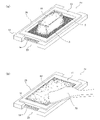
- the makisu 50 is first installed in the makisu installation portion 40 inside the base plate 20 as shown in FIG. 9 (a), and then as shown in FIG. 9 (b).
- the sheet-shaped food S is placed on the upper surface 51 of the makisu 50 from above, and then the molding frame 10 is placed on top of it as shown in FIGS. 2 and 10 (a) for molding.
- the lower opening of the through window 30 of the frame 10 is closed by the upper surface of the base plate 20, that is, the upper surface of the sheet-shaped food S placed on top of the makisu 50 to form the rice rice storage space 31.
- plan view shape of the molded frame 10 and the through window 30 inside the molded frame 10 can be appropriately determined according to the desired molded outer shape of the cooked rice plate, and can be, for example, substantially circular, trapezoidal, or triangular. ..
- sheet-shaped food S in addition to general processed foods such as seaweed and kelp board, natural foods such as perilla may be used, and those standardized so as to have a certain shape and dimensions should be used. Is preferable.
- the sheet-shaped food S standardized in this way is, for example, a substantially square in a plan view of 200 mm to 210 mm in length ⁇ 180 mm to 200 mm in width for “all types”, and all types for “two-cut (half-cut)”. Approximately 1/2 area of all types, 95 mm to 105 mm in length x 180 mm to 200 mm in width, and a rectangular shape in a plan view. 70 mm x 180 mm to 200 mm in width, "6 cuts in width (six cuts)" has a specific size and shape such as approximately 1/6 area of all types and 25 mm to 35 mm in length x 180 mm to 200 mm in width. , It is appropriately selected according to the desired form and size of the rice food.
- the jig A1 designs the molded frame 10 and the base plate 20 according to the dimensions and shapes of the sheet-shaped food S of a certain standard.
- the thickness of the molded frame 10 is substantially the same as the thickness of the plate-shaped cooked rice molded by the frame 10, it can be appropriately determined according to the desired thickness of the plate-shaped cooked rice.
- it is preferably 8 mm to 12 mm.
- the material of the molded frame 10 and the base plate 20 is not particularly limited, but maintenance can be improved by using, for example, resin.
- the inner side surface 13 of the molded frame 10, which is the contact surface with the cooked rice R1, that is, the lower molded surface 21a of the side molded surface 13 and the upper surface 21 of the base plate 20, is subjected to a sliding process that suppresses the adhesion of cooked rice as much as possible. It may be that.
- a metal coating such as ceramic, a slip resin coating such as a fluororesin, and a fine polishing process can be adopted.
- the cooked rice R1 stored in the cooked rice storage space 31 of the jig A1 is pressed downward with a leveling spatula 70 so that the lower surface abuts on the upper surface of the molded frame 10.
- a leveling spatula 70 By spreading it evenly over the entire space 31, it is molded into a molded rice lump R2 that follows the outer shape of the cooked rice storage space 31 and has the same thickness as the thickness of the molded frame 10.
- the plate-shaped cooked rice R3 thus obtained is obtained by placing an ingredient I such as luncheon meat or omelet on the upper surface thereof, and winding the plate-shaped cooked rice R3 as it is through a makisu 50. By folding it, it is shaped into a bent rice ball, that is, cooked rice food R4, which is provided at stores and the like.
- the plate-shaped cooked rice molding jig A1 has a unit structure of a special combination of the molding frame 10 and the base plate 20, and is wound or folded using the plate-shaped cooked rice R3 or the same plate-shaped cooked rice R3. It is an epoch-making jig that reduces the burden of a series of molding and manufacturing work on the cooked rice food R4 in the form of music, and allows anyone to continuously manufacture the cooked rice food R4 easily, stably and quickly.
- the cooked rice molding apparatus B of the present invention (hereinafter, also simply referred to as the present appliance B). ) Is installed at a transport unit 100 for transporting the plate-shaped cooked rice molding jig A1 and a start end portion or a middle portion of the transport unit 100 as shown in FIG. A cooked rice supply unit 200 for discharging a predetermined amount of cooked rice R1 to the inside of the jig A1 is provided.
- the apparatus B is in the transport direction of the cooked rice unit 100 in order to carry out each manufacturing process of the cooked rice R3 and the cooked rice food R4 via the cooked rice molding jig A1 transported by the cooked rice unit 100. It is a structure that allows a plurality of or a single worker to be placed on orthogonal sides, that is, a simple and compact structure that is the minimum necessary for molding plate-shaped cooked rice R3 and manufacturing cooked rice food R4.
- this device B functions as a "rice food production line" for carrying out each manufacturing process in an orderly manner by a worker, and can be installed in a limited narrow work space such as a kitchen in a store for work. It can be said that it is an epoch-making device for the restaurant and retail industry, which can dramatically improve the efficiency and can provide the rice food R4 freshly made in the store.
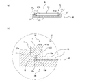
- FIGS. 5 (a) and 5 (b) are schematic cross-sectional views showing a fitted state between a base plate and a molded frame.
- the jig A1 includes a molded frame 10 having a through window 30 formed by a side molding surface 11 for molding the outer peripheral side portion of the plate-shaped cooked rice R3, and the plate-shaped cooked rice.
- a base plate 20 having a lower molding surface 21a on the upper surface 21 for molding the bottom side portion is provided.
- the jig A1 has a cooked rice storage space 31 for storing cooked rice R1 by covering the through window 30 from below with the base plate 20 in a state where the molded frame 10 is placed on the base plate 20.
- a makisu installation portion 40 for installing the makisu 50 between the molding frame 10 and the base plate 20 is formed.
- the base plate 20 is a flat plate having a predetermined thickness, and the central portion of the front and rear end edges of the flat surface of the base plate upper surface 21 is viewed in a plan view.
- the cutout portions 22 and 23 are formed in a substantially H-shape in a plan view.
- the dimensions of the base plate 20 are not particularly limited as long as the bottom portion of the plate-shaped cooked rice can be molded into a flat surface, for example, the width is 125 to 130 mm, the front-back length is 260 to 264 mm, and the thickness is 3 to 5 mm.
- the dimensions of the makisu installation portion 40 may be as long as the makisu 50 can be installed between the molded frame 10 and the base plate 20, for example, a width of 100 to 105 mm, a front-rear length of 260 to 264 mm, and a thickness of 3 to 5 mm.
- the thickness (height) of the makisu installation portion 40 is formed so as to be equal to or larger than the sum of the thickness of the makisu 50 and the thickness of the sheet-shaped food S.
- the height of the makisu setting portion 40 is such that the makisu crimping protrusion 18 is fitted into the makisu setting portion 40. Considering the clearance, the total thickness of the makisu 50, the sheet-shaped food S, and the makisu crimping protrusion 18 is substantially the same.
- the makisu installation portion 40 is a pair of makisu installation step portions 41, 41 having an inner side surface 42 as a contact surface that abuts on the outer surface 52 of the makisu 50 and an upper surface 43 as a mounting surface of the molding frame 10.
- the makisu installation step portions 41 and 41' contact and engage with the four-sided outer portions 52 of the makisu 50, respectively, on the left, right, front and back sides of the makisu 50.
- Anything that regulates movement for example, it may be formed in a protruding shape, and can be appropriately changed according to the size and shape of the makisu 50 to be used.
- the step portions 41 and 41'for installing the makisu of the present embodiment are each formed in an elongated and substantially U-shape in a plan view, and the U-shaped open side is inside the base plate 20.
- the left and right center lines C of the base plate 20 are arranged so as to face each other in a line symmetry with the center, and as shown in FIGS. 3 (c) and 3 (d), the left and right end edges and the front and rear end edges of the base plate 20 are arranged. It is formed so as to project from the upper surface 21 of the base plate to a step portion having an upward convex shape along the left and right ends.
- the stepped portions 41 and 41'for installing the rolls correspond to the vertical sides in a U-shape in a plan view, and are long squares extending in the front-rear direction along the left and right edges of the base plate 20. It corresponds to the rod-shaped central long side wall portions 42, 42'and the upper and lower horizontal sides in a plan view, and is bent at a right angle along the corners of the base plate 20 at the front and rear ends of the central long side wall portions 42, 42'. It is composed of a short square plate-shaped front short side wall portion 43, 43'and a rear side short side wall portion 44, 44'.
- the step portions 41, 41'for installing the makisu having such a configuration arrange the central long side wall portions 42, 42'at the left and right ends of the base plate upper surface 21, and also arrange the front short side wall portions 43, 43'and the rear side.
- the short side wall portions 44, 44' are arranged on the left and right sides of the front and rear ends of the base plate upper surface 21, and two of them are projected from the base plate upper surface 21.
- the dimensions of the stepped parts 41, 41'for installing the makisu are: width 3 to 7 mm, front and rear length 220 to 224 mm, thickness (height) 3 to 5 mm, front side short side wall part for the central long side wall parts 42, 42'.
- the thickness of the makisu installation step portions 41 and 41' is equal to the thickness of the makisu installation portion 40 described above. Further, the installation interval between the pair of makisu installation step portions 41, 41'may be such that the makisu installation portion 40, that is, the makisu 50 can be installed between them.
- the upper surfaces 41a, 41a'of the step portions 41, 41'for installing the makisu are parallel to the upper surface 21 of the base plate, and the upper surfaces of the central long side wall portions 42, 42', the front short side wall portions 43, 43', and the rear.
- the side short side wall portions 44 and 44' are formed as a horizontal flat surface with the upper surfaces flush with each other, and function as a mounting surface for the molded frame 10 in the molded frame fitting portion 60 described later.
- the inner side surfaces 41b and 41b'of the step portions 41 and 41'for installing the makisu are formed on a vertical flat surface orthogonal to the upper surfaces 41a and 41a', and the outer surfaces 52 and 52'of the makisu 50. It functions as a regulating surface that regulates the front-back and left-right movements of the makisu 50 fitted to the makisu installation portion 40 facing the surface.
- the inner side surfaces of the central long side wall portions 42 and 42' are each of the sheet-shaped food of the makisu 50 described later. It is formed on a contact surface that faces and abuts on the left and right outer surfaces of the placement portion 53.
- the inner side surfaces of the front and rear short side wall portions 43, 43', 44, 44' are the left and right front and rear end outer surfaces and the front and rear handle piece portions 54, 55 of the sheet-shaped food placing portion 53 of the makisu 50, respectively. It is formed on the contact surface that faces and abuts on the left and right outer surfaces of the above.
- the makisu 50 which is fitted to the makisu installation portion 40, is formed in a convex shape on the front-rear side in a plan view as shown in FIGS. 1 and 2, and can be bent and wound in the longitudinal direction. ing.
- the makisu 50 is made by bending a sheet-shaped food placing portion 53 for placing the sheet-shaped food S and a plate-shaped rice R3 molded on the makisu 50.
- the makisu 50 is composed of front and rear handle pieces 54 and 55 for picking up the makisu 50 from the makisu installation portion 40 with fingers when winding.
- the sheet-shaped food placing portion 53 has a plan-viewing square plate shape that occupies most of the area of the makisu installation portion 40 of the base plate 20, and has a fixed standard sheet-shaped food placing portion 53 on which the base plate 20 is placed and a plan view.
- the shapes are almost the same, with a width of 100 to 105 mm and a front-back length of 200 to 205 mm.
- the sheet-shaped food placing portion 53 When the sheet-shaped food placing portion 53 is installed by extending the makisu 50 to the makisu installing portion 40, the sheet-shaped food placing portion 53 is horizontally deployed on the horizontal base plate upper surface 21 so that the upper surface thereof is parallel to the base plate upper surface 21. It functions as a lower molded surface 21a.
- front-rear side handle pieces 54 and 55 are plan-view rectangular pieces corresponding to the plan-view shapes of the front-rear side notches 22 and 23 of the base plate upper surface 21 described above, and are the front-rear ends of the sheet-shaped food placing portion 53. It is formed in the central part so as to project outward in the front-rear direction, and has a width of 60 to 64 mm and a front-back length of 33 to 37 mm.
- the front and rear handle pieces 54 and 55 are exposed at the front and rear notches 22 and 23 of the base plate 20 when the makisu 50 is extended and placed on the makisu installation portion 40. It functions as a handle for picking with fingers from above and below.
- the makisu 50 is a mat-shaped cooking utensil that is laid under the food to roll the food into a rolled shape or bend it to form a bent shape, and is a plurality of bamboos having the same length.
- the bamboo blinds are connected with a string so that they can be bent and wound in a certain direction.
- the makisu 50 is composed of a plurality of elongated bamboo strings whose lengths are arranged in parallel, and a string body that connects adjacent bamboo strings at predetermined positions on the length of the bamboo strings. Is the one in which the bamboo skin is left, and is configured to improve the slipperiness of the upper surface by connecting and knitting the bamboo skin with a string body in a state where the bamboo skin is oriented upward.
- the makisu 50 is not particularly limited in terms of material and structure as long as it can be bent and wound in a certain direction as it is on which the plate-shaped cooked rice R3 is placed. It may be made of resin.
- the thickness of the makisu 50 is, for example, 3 mm to 7 mm in order to match the thickness of the above-mentioned makisu installation portion 40 (makisu installation step portions 41, 41').
- the makisu installation portion 40 and the makisu 50 are configured to be able to be fitted to each other from a pair of left and right U-shaped makisu installation step portions 41, 41'protruding from the base plate 20. ing.
- the molded frame fitting portion 60 that allows the molding frame 10 to be fitted to the upper surface 21 of the base plate 20 at a position above the makisu installation portion 40. Is forming.
- the molding frame fitting portion 60 is located above the makisu installation step portions 41, 41'on which the molding frame 10 is placed and the makisu installation step portions 41, 41'. It is composed of frame installation step portions 61, 61'that project upward so that the molded frame 10 can be fitted along the outer shape of the frame.
- the inner side surfaces 61b and 61b' are made contact surfaces that abut on the outer surface 14 of the molding frame 10, and the height positions of the upper surfaces 61a and 61a' are set.
- the inner side surfaces 61b of the frame installation step portions 61 and 61' function as a regulating surface that faces the outer surface 14 of the molded frame 10 and regulates the front-back and left-right movements of the molded frame 10.
- the frame installation step portions 61 and 61' are engaged with each other on the four outer sides of the molded frame 10 at the upper position of the makisu installation portion 40 in the fitted state of the molded frame 10, and the left and right front and rear portions of the molded frame 10 are engaged with each other. It suffices as long as it regulates the movement of.
- the frame installation step portions 61 and 61'of the present embodiment are formed in a substantially U-shape in a plan view having a substantially similar shape larger than the makisu installation step portions 41 and 41'.
- the frame installation step 61, 61' encloses the makisu installation step 41, 41'from the outside, and the U-shaped open side faces the inside of the base plate 20, and the left and right center lines of the base plate 20.
- C is arranged line-symmetrically with respect to the center, and is formed so as to project upward from the base plate upper surface 21 along the left and right end edges of the base plate upper surface 21 and the left and right ends of the front and rear end edges.
- the frame installation step portions 61 and 61' correspond to the vertical sides having a U-shape in a plan view
- the frame installation step portions 61 and 61' correspond to the vertical sides of the base plate 20 in the front-rear direction along the left and right edges of the base plate 20. It corresponds to the elongated square rod-shaped central long side wall portion 62 and the upper and lower horizontal sides in a U-shape in a plan view, and is bent at a right angle along the corner portion of the base plate 20 at the front and rear ends of the central long side wall portion 62. It is composed of a short square plate-shaped front short side wall portion 63, 63'and a rear short side wall portion 64, 64'.
- Such frame installation step portions 61, 61' arrange the central long side wall portions 62, 62'on the left and right edge edges of the base plate upper surface 21, and the front and rear short side wall portions 63, 63', 64, 64'. Are arranged on the left and right sides of the front and rear ends of the base plate upper surface 21, and two protrusions are provided from the base plate upper surface 21.
- the dimensions of the frame installation step 61 are as follows: width 6 to 10 mm, front and rear length 260 to 264 mm, thickness (height) 7 to 11 mm, front and rear short side wall portions 63, 63 for the central long side wall portions 62, 62'.
- width is 23 to 27 mm
- front-back length is 18 to 22 mm
- thickness (height) is 7 to 11 mm, respectively.
- the frame installation step portions 61, 61' are formed on a horizontal flat surface whose upper surfaces 61a, 61a'are parallel to the upper surface 21 of the base plate, and the inner side surfaces 61b, 61b'are orthogonal to the upper surfaces 61a, 61a'. It is formed on a vertical flat surface.
- the upper surfaces 61a and 61a'of the frame installation steps 61 and 61' are the upper surfaces of the central long side wall portions 62 and 62'and the front and rear short side wall portions 63, 63', 64 and 64'. Is a horizontal flat surface.
- the inner side surfaces 61b and 61b'of the frame installation step portions 61 and 61' face each other to the left and right outer surfaces of the molded frame 10 and the front and rear side short side walls.
- the inner side surfaces of the portions 63 and 64 are formed on the contact surfaces facing the front and rear outer surfaces at the corners of the molded frame 10.
- the base plate 20 has the shape of the frame installation step portions 61, 61'protruding upward on the outermost side in a plan view, and the frame installation step portions 61, 61'inside the frame installation step portions 61, 61'.
- the frame installation step portions 41, 41' are provided along the frame installation step portions 61, 41', which are lower than the height of the frame installation step portions 61, 61'and project upward.
- the facing surfaces of the front and rear short side wall portions 63, 63', 64, 64' of the pair of frame installation step portions 61, 61' are as shown in FIGS. 3 (a) and 3 (c).
- the front and rear short side wall portions 43, 43', 44, 44'of the stepped portions 41, 41'at the lower position should be flush with the facing surfaces, and the front and rear sides should be between the front and rear facing surfaces.
- the cutouts 22 and 23 are formed.
- the base plate 20 is the left and right side edge portions corresponding to the left and right flange portions of the base plate having an H-shape in a plan view, and descends by two steps from the outside to the inside.
- the left and right steps that are stepped in cross-sectional view and substantially U-shaped in plan view upward, most of the plan view square surface at the center of the upper surface 21 at the lowest position exposed between the steps. Is the lower molded surface 21a of the plate-shaped rice.
- the lower step portion elements are designated as makisu installation step portions 41, 41'
- the upper step portion elements are designated as frame installation step portions 61, 61'
- the upper step portion is wound inward by the corner facing step portion.
- the bamboo blind installation portion 40 and the molded frame fitting portion 60 are formed.
- the makisu 50 and the molded frame 10 are sequentially fitted and installed on the base plate 20 having such a configuration.
- the molded frame 10 is a rectangular flat plate having a predetermined thickness as shown in FIGS. 4 (b) to 4 (d), and has a central portion thereof as shown in FIG. 4 (a). It is formed through a through window 30 having a rectangular shape in a plan view and having a shape similar to the outer shape of the frame. That is, the molded frame 10 is configured as a flat rectangular frame in the shape of a square frame in a plan view having a through window 30 inside.
- the upper surface 11 and the lower surface 12 of the molded frame 10 are formed on a flat surface parallel to each other, and the inner surface 13 and the outer surface 14 of the molded frame 10 are formed. Is formed on a flat surface orthogonal to the upper and lower surfaces 11 and 12, respectively, of the molded frame 10.
- the inner side surface 13 of the molded frame 10 forms a through window 30 and functions as a side molded surface 13 of the plate-shaped cooked rice R3.
- the upper surface 11 is for leveling the cooked rice stored in the cooked rice storage space 31 and spreading it while bringing the spatula surface of the spatula 70 into surface contact to mold the upper portion of the plate-shaped cooked rice R3 substantially flush with the upper surface 11.
- the lower surface 12 functions as a reference surface for the leveling spatula forming the virtual upper molded surface, and the lower surface 12 functions as a mounting surface for the molded frame 10 on the base plate 20 (molded frame fitting portion 60).
- the molded frame 10 has a long right-angled square rod-shaped left and right side wall portions 15 and 15'and left and right side wall portions 15 and 15'extended in the front-rear direction. It is composed of short right-angled square plate-shaped front and rear side wall portions 16 and 17 that extend orthogonally in the extension direction of the left and right side wall portions 15 and 15'so as to connect the front end portions of the above.
- the through window 30 has four right-angled corners surrounded on all sides by the inner side surfaces 13 of the left and right side wall portions 15, 15'and the front and rear side wall portions 16, 17 in the molded frame 10, and has an upper and lower opening.
- a rice storage space 31 as a virtual rectangular parallelepiped space surrounded by a flush virtual vertical plane and an inner side surface 13 of the molded frame 10 is formed on the upper and lower surfaces 11 and 12 of the molded frame 10 that closes 32 and 33.
- the outer dimensions of the molded frame 10 are formed so as to be slightly larger than the outer dimensions of the sheet-shaped food, and the through window is formed.
- the dimension 30 is formed so as to be slightly smaller than the outer dimension of the sheet-shaped food.
- the molded frame 10 and the through window 30 inside the molded frame 10 have a plan-viewing outer shape similar to the plan-viewing outer shape of the rectangular sheet-shaped food S, and the molded frame 10 is slightly larger than the outer shape of the sheet-shaped food S.
- the through window 30 is made slightly smaller than the outer shape of the sheet-shaped food S so as to have a plan-viewing rectangular shape that fits on the peripheral edge of the sheet-shaped food S. It is formed to fit in.
- the dimensions of the molded frame 10 may be less than or equal to the dimensions of the base plate 20 and greater than or equal to the dimensions of the sheet-shaped food S, and have a width of 108 to 10 mm, a front-rear length of 218 to 222 mm, and a thickness of 8 to 12 mm.
- the size of the through window 30 is smaller than the size of the sheet-shaped food S, and has a width of 88 to 92 mm, a front-rear length of 178 to 182 mm, and a thickness of 8 to 12 mm.
- the molded frame 10 can be adapted to the shape of the sheet-shaped food S (sheet-shaped food placing portion 53 of the makisu 50), and the molded frame 10 is placed along the peripheral edge of the sheet-shaped food S. Therefore, the plate-shaped cooked rice R3 can be molded by using the exposed surface of the sheet-shaped food 101 exposed by closing the inner through window 30 downward as the lower molding surface.
- the molded frame 10 has an upper surface 11 in which the lower surface of the leveling spatula 70, which will be described later, abuts on the surface of the molded frame 10, and a lower surface 12 in which a part of the upper surface of the sheet-shaped food S abuts. 16 and 17 are formed wider than the left and right side wall portions 15 and 15'.
- the molded frame 10 has a width of 8 to 12 mm for the left and right side wall portions 15 and 15', a front and rear length of 218 to 222 mm, a thickness (height) of 8 to 5 mm, and a width of 88 for each of the front and rear side wall portions 16 and 17. It is said to be ⁇ 92mm, front and back length 18 ⁇ 22mm, thickness (height) 8 ⁇ 5mm.
- the mounting contact area is expanded as much as possible, and the mounting and positioning of the molded frame 10 along the entire peripheral edge of the sheet-shaped food S becomes easy.
- the mounting work of the frame 10 can be simplified.
- the makisu 50 is installed in the makisu installation portion 40, and the molded frame 10 is placed on the base plate 20 on the upper surface 51 of the makisu.
- the makisu crimping protrusion 18 corresponding to the contact is formed so as to protrude downward from the lower opening edge 33a of the through window 30.
- the makisu crimping protrusion 18 is a bottom-viewing substantially square-shaped protrusion formed endlessly so as to border the lower opening edge 33a of the molding frame 10, and is formed so as to project downward from the lower surface 12 of the molding frame 10. is doing.
- the inner side surface 18a of the makisu crimping protrusion 18 has a vertical surface integrated with the inner side surface 13 of the molded frame 10 as shown in FIGS. 4 (a) to 5 (b). Further, the lower end surface 18b of the makisu crimping protrusion 18 is parallel to the upper and lower surfaces 11 and 12 of the molded frame, and faces the upper surface 21 of the base plate and presses the upper surface of the makisu 50 (sheet-shaped food S) downward. It has a flat crimping surface. Further, the outer surface 18c of the makisu crimping protrusion 18 is a flat engaging surface that abuts and engages with the inner side surfaces 41b, 41b'of the makisu installation step portions 41, 41'.
- the makisu crimping protrusion 18 has a width that does not interfere with the makisu installation step portions 41 and 41', and has a square-shaped outer shape when viewed from the bottom.
- the outer shape of the sheet-shaped food placing portion of the bamboo blind 50 is substantially the same as that of the sheet-shaped food placing portion, and the bamboo blind 50 is formed so as to be fitable to the makisu setting portion 40.
- the width of the makisu crimping protrusion 18 is, for example, 3 to 7 mm.
- the makisu crimping protrusion 18 is a protrusion in which the lower end surface 18b is crimped to the upper surface 51 of the makisu 50 when the makisu 50 is installed in the makisu installation portion 40 and the molded frame 10 is placed on the base plate 20. It has a length (thickness).
- the protruding length of the makisu crimping protrusion 18 is, for example, 1 to 5 mm.
- the thickness of the plate-shaped cooked rice molded by the jig A1 is the same as the sum of the thickness from the upper surface 11 to the lower surface 12 of the molded frame 10 and the thickness of the makisu crimping protrusion 18 (protrusion). ..
- the molded frame 10 is formed in a downward convex shape by the makisu crimping protrusion 18, and the makisu crimping protrusion 18 of the downward convex portion is fitted to the makisu installation portion 40 of the base plate 20. It is configured to be possible.
- the gap that is inadvertently generated between the lower surface 12 of the molded frame and the upper surface 51 of the makisu can be reliably closed, and the lower end of the cooked rice is spread out in the rice storage space. It is possible to produce plate-shaped cooked rice with good moldability by preventing the cooked rice from inadvertently leaking from the edge portion and orderly molding the lower corner portion. Further, by fitting the makisu crimping protrusion 18 of the molding frame 10 into the makisu installation portion 40 of the base plate 20, it is possible to prevent the molding frame 10 from being inadvertently displaced on the base plate 20.
- the jig A1 has a special unitized structure in which the molded frame 10 and the base plate 20 are fitted to each other and come into surface contact with each other, so that workability during molding due to the binding force peculiar to cooked rice is obtained. It is configured so that it is possible to produce plate-shaped cooked rice with good moldability without causing deterioration or "thickness spots", and it is possible to easily perform shaping work to the final product form such as winding and bending after that. There is.
- Plate-shaped cooked rice molding jig according to the second embodiment Next, the configuration of the plate-shaped cooked rice molding jig according to the second embodiment will be described. Hereinafter, the same configurations as those of the plate-shaped cooked rice molding jig according to the first embodiment are designated by the same reference numerals, and the description thereof will be omitted. 7 and 8 are exploded perspective views showing the configuration of the plate-shaped cooked rice molding jig according to the present embodiment.
- the jig A2 has substantially the same configuration as the plate-shaped cooked rice molding jig A1 according to the first embodiment, but is configured in that the molding frame 10 is pivotally supported by one end of the base plate 20 so as to be rotatable upward. To be different.
- the bearing portion 24 is formed so as to project upward at one end of the base plate 20, and the molded frame 10 is rotatably pivotally supported on the bearing portion 24. It is composed of.
- two bearing portions 24, 24' are formed upward on the left and right sides of the longitudinal end of the base plate 20, and the longitudinal end portion of the base plate 20 is fitted between the bearing portions 24, 24'. It is pivotally supported so as to be vertically rotatable via the pivot shaft 25 in the worn state.
- the bearing portions 24 and 24' have a curved surface shape in which the upper surfaces 24b and 24b' have a semicircular arc shape when viewed in the axial direction of the pivot shaft 25, and are centered on the pivot shaft 25 at a fixed position on the base plate 20.
- the molded frame 10 can be rotated upward from the lying down position.
- the front side wall portion 16 of the molded frame 10 is cut out in a plan view shape at the outer corner portions on the left and right sides so as to correspond to the fitting between the bearing portions 24 and 24', and the bearing fitting portion 19 is formed on the front side. is doing.
- the bearing fitting portion 19 and the bearing are inserted so that the pivot shaft 25 is inserted in the state where the bearing fitting portion 19 of the molded frame 10 is fitted between the bearing portions 24, 24'of the base plate 20. It is a shaft hole formed through the portions 24 and 24'in the left-right direction with a coaxial center.
- the molded frame 10 is formed as a makisu installation portion 40 with a clearance corresponding to the thickness of the makisu 50 between the base plate 20 and the molded frame 10 in an inverted posture in which the lower surface 12 is parallel to the upper surface 21 of the base plate 20.
- the bearing portions 24 and 24'of the base plate 20 are pivotally supported via the pivot shaft 25.
- the molded frame 10 has a horizontally long square rod-shaped bearing portion 24 formed so as to project upward at one longitudinal end of the base plate 20, and the left and right front end portions are externally fitted to the bearing portion 24. It is composed of a frame body 10'which has a substantially U-shape in a plan view and is axially mounted so as to be rotatable up and down.
- the bearing portion 24 has an upper surface 24b as a flat surface and an inner side surface 24c as a vertical surface orthogonal to the upper surface 24b, and is formed so as to lie down at the center of one end of the base plate 20 and project upward.
- the bearing portion 24 has an inverted L-shape when viewed from the side, and forms a makisu entry groove 26 in which the tip of the L-shaped end side faces inward and the inner base portion is recessed inward.
- the frame main body 10' is composed of left and right side wall portions 15 and 15'and a rear side wall portion 17 in which the front side wall portion 16 is eliminated from the molded frame 10. That is, the molded frame 10 is composed of a shaft attachment between the frame main body 10'and the bearing portion 24 of the base plate 20 that also serves as the front side wall portion 16 of the molded frame 10, and the inner side surface of the frame main body 10'and the bearing.
- the through window 30 is formed inward by the inner side surface of the portion 24.
- the frame body 10' is in an inverted posture in which the lower surface 12 is parallel to the upper surface 21 of the base plate 20 with respect to the base plate 20, and the upper surface 11 is substantially flush with the upper surface 24b of the bearing portion 24. It is pivotally supported by the bearing portion 24 so as to do so.
- the jig A2 pivotally supports the molded frame 10 with respect to the base plate 20 so as to be vertically rotatable via the pivot shaft 25 at one end, and the lower surface 12 of the molded frame is parallel to the upper surface 21 of the base plate.
- the lower opening edge 33a of the through window 30 of the molding frame 10 is closed by the upper surface 21 of the base plate 20 to form the rice storage space 31.
- the molding frame 10 and the base plate 20 are formed into an integrated unit structure via the pivot shaft 25, the pivot shaft 25 is formed.
- the rotation operation of the molded frame 10 through the base plate 20 facilitates the positioning work of the molded frame 10 and the frame removal work of pulling out and removing the molded frame 10 from the molded rice lump R2 molded in the cooked rice storage space 31. Can be done.
- a leveling spatula used for the plate-shaped cooked rice molding jig of the present invention Next, the configuration of the leveling spatula for leveling the cooked rice stored in the cooked rice storage space of this jig will be described. 8 (a) and 8 (b) are side views and plan views showing the structure of the leveling spatula.
- the leveling spatula 70 is composed of a grip portion 71 and a flat spatula main body portion 72 extended on one side of the grip portion 71. , Used to even out the cooked rice stored in the cooked rice storage space 31 on the bottom surface of the spatula main body 72.
- the grip portion 71 has a flat and elongated shape with a constant width that can be easily grasped by hand, and the width is gradually narrowed from the base end to the tip. It is formed in a constricted shape with the main body 72 so that force can easily enter when grasped by hand.
- the grip portion 71 is formed in an arc shape in cross section. Specifically, the grip portion 71 forms a recess 71c for abutting and placing the ventral surface of the finger on the upper surface 71a in an elongated hole shape along the axial direction of the grip portion 71, and the lower surface 71a'is the grip portion 71. It is formed on a curved convex surface continuous with the left and right outer portions 71b and 71b'along the axial direction of the above.
- the spatula main body 72 is a flat plate-shaped portion having a substantially constant thickness as a whole and has a substantially rectangular shape in a plan view, and the lower surface 72a'is a cooked rice R1 or a book. It is a contact surface with the upper surface 11 of the molded frame of the jig, and is connected to the grip portion 71 in a manner inclined with respect to the virtual axis core line P of the grip portion 71.
- the spatula main body 72 has a tip edge portion 73 arranged on the tip side and extending linearly as an edge portion forming a substantially rectangular shape in a plan view, and the spatula body portion 72 gently bulging outward from one side of the grip portion 71 and extending in a curved shape. It has a base end edge portion 73'and left and right end edge portions 74, 74'that extend linearly at both ends of the tip end edge portion 73.
- the tip edge portion 73 forms a substantially right-angled front left and right side corner portions 75, 75'together with the left and right edge portions 74, 74', and the left end edge portion 74 is the other side 71b'of the grip portion 71.
- the right edge 74' forms a substantially obtuse angled posterior right corner 76' together with the proximal edge 73'.
- the spatula main body 72 is formed so that the lengths of the left and right edge portions 74 and 74'are at least 1/2 of the vertical length of the cooked rice storage space 31. Further, the spatula main body 72 has one corner 76 or its vicinity as a connection base with the grip 71 among the four corners 75, 75', 76, 76' in a plan view, and is a virtual axis of the grip 71. The center of gravity G of the spatula main body 72 is arranged on or near the core line P.
- the spatula main body 72 arranges the rear left corner portion 76 and the diagonal front right corner portion 75'at a relative position substantially point-symmetrical with respect to the center of gravity G of the spatula main body 72 of the grip portion 71.
- the center of gravity G of the spatula main body 72 is arranged at a position near the virtual axis core line P of the grip portion 71, and is connected to the grip portion 71 continuously.
- the center of gravity G of the spatula main body 72 is a straight line connecting the midpoints of the opposite sides of each square, that is, the midpoint of the tip edge portion 73 and the center of the base end edge portion 73'. It is an intersection formed by a vertical virtual vertical straight line (AA single point chain line) connecting points and a horizontal virtual horizontal straight line (BB single point chain line) connecting midpoints of the left and right edge portions 74 and 74'.
- AA single point chain line vertical virtual vertical straight line
- BB single point chain line horizontal virtual horizontal straight line
- the spatula body portion 72 has a tip edge portion 73 obliquely provided at a predetermined angle on the virtual axis core line P of the grip portion 71 with respect to the grip portion 71. That is, the leveling spatula 70 is a pair of left and right edge portions 74, 74'parallel to each other on both sides of the virtual axis core line P of the grip portion 71 in the spatula main body portion 72 having a substantially rectangular shape in a plan view. Has a shape in which the directions along which the left and right edge portions 74 and 74'are along are inclined by a predetermined angle with respect to the virtual axis core line P.
- the spatula main body 72 extending to the central portion between the left and right edge portions 74 and 74'of the spatula main body 72 is bisected into left and right halves.
- the line (AA one-dot chain line) is inclined with respect to the virtual axis core line P of the grip portion 71, and the inclination angle ⁇ is, for example, about 30 ° to 60 °.
- the leveling spatula 70 has most of the front half of the spatula body 72 on the left and right sides centered on the virtual axis P of the grip 71.
- the center of gravity G2 in the front half of the spatula main body 72 is eccentrically arranged so as to be arranged on one side of the spatula, and is formed in a substantially square shape in a plan view.
- the spatula main body 72 has a curved surface shape that is gently curved as a whole as shown in FIG. 8A, and is gently convex downward so as to position the curved top on the virtual axis P of the grip portion 71.
- the upper surface 72a is formed as a curved concave surface and the lower surface 72a'is formed as a curved convex surface.
- the contact area with the cooked rice R1 is finely adjusted along the lower surface 72a'of the spatula main body 72 to accurately perform the cooked rice R1 leveling operation while adjusting the leveling amount of the cooked rice. Can be done.
- Example of using the plate-shaped cooked rice molding jig according to the present invention Next, an example of using the plate-shaped cooked rice molding jig according to the present invention will be described. Hereinafter, an example of using the above-mentioned leveling spatula 70 and the plate-shaped cooked rice molding jig A1 according to the first embodiment will be described in detail, but the plate-shaped cooked rice molding jig is a pivotal plate according to the second embodiment. Of course, even with the cooked rice molding jig A2, plate cooked rice can be molded in the same manner.
- the makisu 50 is extended and fitted to the makisu installation portion 40 between the makisu installation step portions 41 and 41'of the base plate 20.
- the makisu 50 has the upper surface 51 parallel to the upper surface 21 of the base plate and the outer surface 52 is the inner side surface 41b of the makisu installation step portions 41, 41'. , 41b'is installed on the base plate 20 facing the surface.
- the sheet-shaped food S is spread flat and placed on the sheet-shaped food placing portion 53 of the makisu 50.
- the sheet-shaped food S has an upper surface parallel to the upper surface 51 of the makisu, that is, the upper surface 21 of the base plate so as to be fitted into the square portion of the makisu installation portion 40 in a plan view.
- the molded frame 10 is fitted to the molded frame fitting portion 60 of the base plate 20.
- the molded frame 10 surface-contacts the outer bottom side edge portion of the lower surface 12 with the upper surfaces 41a and 41a'of the step portions 41 and 41'for installing the makisu.
- the outer surface 14 is faced with the inner side surfaces 61b, 61b'of the frame installation step portions 61, 61', and is installed on the base plate 20 at a position above the makisu 50.
- the makisu crimping protrusion 18 of the molded frame 10 is in a state of being crimped to the upper peripheral edge of the sheet-shaped food S on the makisu 50 as shown in FIG. 5 (b).
- a predetermined amount of cooked rice R1 is placed in the center of the upper surface of the exposed sheet-shaped food S in the cooked rice storage space 31.
- the cooked rice R1 is stored in a container such as a tapper having the same capacity as the cooked rice storage space 31 to form a substantially rectangular parallelepiped mass.
- the cooked rice R1 is arranged diagonally in the cooked rice storage space 31 so that the four corners correspond to the four corners of the cooked rice storage space 31, and the intersections of the diagonal lines of the cooked rice R1 are the diagonal lines of the cooked rice storage space 31. It is placed in the center of the upper surface of the sheet-shaped food S so as to be arranged at the intersection of.
- the cooked rice R1 is spread evenly so as to fill the inside of the cooked rice storage space 31 without a gap with the cooked rice Bella 70.
- the curved convex lower surface 51'of the spatula main body 72 of the leveling spatula 70 is applied to the cooked rice R1 in the center of the cooked rice storage space 31 while being substantially parallel to the upper surface 11 of the molding frame 10, and is leveled while being pressed downward. spread.
- the cooked rice R1 stores four corners of the cooked rice R1 from the center of the cooked rice R1 by the cooked rice R1 based on the relative positions of the respective parts of the cooked rice R1 and the cooked rice storage space 31. It is sequentially leveled and spread so as to extend toward the four corners of the space 31.
- the upper surface of the cooked rice R1 spread over the entire area of the cooked rice storage space 31 is pushed downward so as to be substantially flush with the upper surface 11 of the molded frame 10 to form a substantially flat surface, which is substantially the same as the thickness of the molded frame 10.
- Molded rice lump R2 having the thickness of the above and following the shape of the cooked rice storage space 31 is molded.
- the makisu crimping protrusion 18 of the molded frame 10 is crimped along the peripheral edge of the sheet-shaped food S placed on the makisu 50, the cooked rice R1 carelessly protrudes from the sheet-shaped food S during leveling and spreading. There is no.
- a plate-shaped molded rice lump R2 that is, a plate-shaped cooked rice R3 along the outer shape of the sheet-shaped food S in a plan view can be molded.
- each of the square-shaped corners of the spatula main body 72 corresponds to each corner of the cooked rice storage space 31 of the molded frame 10, and the cooked rice is placed and stored on the lower molded surface of the base plate.
- the cooked rice is placed and stored on the lower molded surface of the base plate.
- a "leveling and spreading molding operation” is performed to mold the molded rice lump R2 in which the sheet-shaped food S corresponding to the above is integrated with the lower bottom surface.
- a shearing force orthogonal to the binding direction between the molded rice lump R2 and the inner side of the molded rice lump R2 is applied to the outer surface of the molded rice lump R2 and the inner surface of the molded rice lump 10.
- the "form removal work" for molding and manufacturing the plate-shaped cooked rice R3 on the base plate 20 is performed by acting on the wearing portion. As a result, as shown in FIG. 11A, a plate-shaped cooked rice R3 having a lower bottom surface integrated with the sheet-shaped food S is molded on the makisu 50 of the base plate 20.
- the plate-shaped cooked rice R3 is molded and manufactured in a state of being placed on the makisu 50 in advance, as shown in FIG. 11 (b), the predetermined ingredient I is placed as it is and the predetermined ingredient I is placed via the makisu 50.
- cooked rice food R4 such as rolled sushi and bent rice balls.
- FIG. 12 is an overall perspective view showing the configuration of the plate-shaped cooked rice molding apparatus
- FIG. 13 is a partially enlarged perspective view showing the configuration of the plate-shaped cooked rice molding apparatus
- FIG. 14 is a partially enlarged perspective view showing the configuration of the plate-shaped cooked rice molding apparatus.
- 15 is a schematic partially enlarged cross-sectional view showing the configuration of a plate-shaped cooked rice molding apparatus.
- one end side is referred to as “upper side in the transport direction” or “start end side”, and the other end side is referred to as “lower side in the transport direction” or “end side”.
- the side on which the worker is placed is referred to as "work side", “one side” or “right side”, and the opposite side is referred to as an ingredient or the like.
- the side on which is installed is referred to as the “ingredient side", “other side” or "left side”.
- the plate-shaped cooked rice molding apparatus B includes the plate-shaped cooked rice molding jig A1 according to the first embodiment and the A2 according to the second embodiment (hereinafter, simply referred to as a book).
- a predetermined amount of rice is placed inside the plate-shaped cooked rice molding jig A from a position above the transport unit 100, which is installed at the start end portion or the middle portion of the transport unit 100 for transporting the transport unit 100 (referred to as jig A). It is provided with a cooked rice supply unit 200 for discharging cooked rice.
- the transport unit 100 is laid on a mounting table 300 having a predetermined height that is easy for an operator to work with with the transport surface horizontal.
- the transport unit 100 is provided with a height from the floor surface to the transport surface at a height position of about 80 cm to 90 cm via the mounting table 300.
- the transport unit 100 has a plate shape of the jig A for slide transport by a single or a plurality of operators sequentially arranged from the upper side to the lower side in the transport direction on one side in the direction orthogonal to the transport direction in a plan view. It functions as a work table for producing cooked rice R3 and cooked rice food R4.
- a plurality of food material storage containers 310 containing various ingredients such as sheet-shaped food S, omelet, luncheon meat, etc. are arranged along the transport direction, and the operator It is possible to carry out the manufacturing process for the plate-shaped rice R3 and the rice food R4 via the jig A in which the ingredients are taken out from the food storage container 310 and sequentially conveyed.
- the length of the transport unit 100 is a series for producing plate-shaped cooked rice R3 and cooked rice food R4 from the supply of cooked rice R1 via the jig A in which at least two workers are sequentially positioned side by side and sequentially transported.
- the length is such that the work process can be carried out, for example, 1.5 to 1.7 m.
- the width of the transport unit 100 is set to be equal to or larger than the front-rear length of the jig A, and the width is such that the jig A can be slid and transported in the transport direction, for example, 250 mm to 290 mm.
- Such a transport unit 100 may be one having a self-conveying driving force for moving the jig A1, for example, a belt conveyor, but basically the jig does not have a driving source. From the viewpoint of space saving and cost reduction, it is preferable to slide and convey the A1 by directly sending it out by an operator.
- the transport unit 100 has a pair of transport rails 110 and 110'arranged in parallel on the mounting table 300 at regular intervals, and both ends of the jig A are placed between the transport rails 110 and 110'.
- the jig A is configured to be slidable and conveyed along the extension direction of the transfer rails 110 and 110'.
- the transport rails 110 and 110' are substantially L-shaped in cross-sectional view, and the guide vertical portion of the vertical portion corresponding to the outer wall portion (outer surface 14) of the jig A abuts. It extends in the direction orthogonal to the guide vertical wall portions 120, 120'from the lower ends of the wall portions 120, 120'and the guide vertical wall portions 120, 120', and abuts on the outer bottom wall portion (lower surface 12) of the jig A. It is composed of guide side wall portions 130 and 130'of the corresponding horizontal portions.
- an L-shaped transport rail 110 for example, an L-shaped steel made of aluminum or a stainless steel material whose surface has been subjected to a smooth surface processing can be adopted.
- the pair of transport rails 110 and 110' have their L-shaped tips, that is, their respective guide side wall portions 130 and 130' facing inward, and the guide vertical wall portion 120'so as to open the inside of the L-shape upward. , 120'are faced to each other and laid in parallel while maintaining a certain interval.
- transport rails 110 and 110'of the present embodiment are provided on a pair of square bar-shaped transport frames 140 and 140' having a predetermined height laid in parallel on the mounting table 300.
- the heights of the guide vertical wall portions 120 and 120' may be as long as they can regulate the jig A from the left and right sides of the transport.
- the jig A (frame installation step portions 61 and 61'of the base plate 20).
- the thickness should be 12 to 16 mm, which is almost the same as the thickness of.
- the widths of the guide horizontal wall portions 130 and 130' are the guide horizontal walls of the pair of transport rails 110 and 110'.
- the width may be such that the front and rear ends on the outer bottom side of the jig A (base plate 20) can be placed on the portions 130 and 130', and the width can be appropriately determined depending on the distance between the transport rails 110 and 110'.
- the distance between the transport rails 110 and 110' is such that the distance between the guide vertical wall portions 120 and 120'is equal to or greater than the front-rear length of the jig A and shorter than the diagonal length of the jig A. Make it an interval.
- the jig A is conveyed with its four outer corners regulated by the guide vertical wall portions 120, 120'and the left and right side wall portions 15, 15'in a constant conveying posture toward the conveying direction.
- the distance between the transport rails 110 and 110'in the present embodiment is such that the distance between the guide vertical wall portions 120 and 120'is substantially the same as the front-rear length of the jig A (for example, 265 to 275 mm).
- the interval is set.
- a waste storage unit 150 for collecting unnecessary waste generated in the manufacturing process is formed below the transport rails 110 and 110'.
- the waste storage unit 150 is orthogonal to each other in the extension direction so as to be spaced apart from each other by a predetermined distance between the transport frames 140 and 140'positions below the transport rails 110 and 110'. It is formed as a square space of an upper opening partitioned by a plurality of horizontally laid square bar-shaped partition walls 141.
- the lower opening of the waste storage unit 150 is substantially closed by the upper surface of the mounting table 300, and a substantially identical rectangular bottom shallow box member 153 such as a bat is fitted and mounted in the waste storage unit 150.
- the upper opening of the waste storage unit 150 can be opened and closed by a lid 151 made of flat flat plates in a plan view that is straddled between adjacent partition walls 141.
- the lid 151 is provided with a waste hole 152 that communicates with the lower waste storage unit 150 in the closed state.
- the lid 151 is configured such that the upper surface position is lower than the transport surface formed by the guide side wall portions 130, 130'of the transport rails 110, 110', and the transport rail 110 is configured. , 110'forms a clearance that makes the outer bottom side surface of the jig A non-contact when the jig A is straddled.
- the clearance between the upper surface of the lid 151 and the outer bottom side surface of the jig A in the transport posture is shown in FIG. 15 (b) when the jig A is pressed downward and bent during the molding operation.
- the outer bottom side surface portion of the jig A is in crimp contact with the upper surface of the lid 151 to stabilize the stop posture of the jig A, for example, about 5 to 10 mm.
- the guide side wall portions 130 and 130' have a plurality of transport rollers 132 rotatably pivotally supported along the extension direction of the transport rails 110 and 110' as shown in FIGS. 12 and 13. , 132'is configured.
- the guide side wall portions 130 and 130' are left and right between the long plate-shaped left and right side frames 133 and 133'that are extended in parallel while maintaining a certain interval, and the left and right side frames 133 and 133'.
- It is configured as a roller conveyor 131, 131 that can be attached to and detached from the transport frames 140, 140'by means of small diameter horizontally long transport rollers 132, 132' that are rotatably attached to the side frames 133 and 133' along the extension direction. ..
- the roller conveyors 131 and 131'for forming the guide side wall portions 130 and 130' may be configured to be able to be arranged side by side so as to extend in the vertical direction as a plurality of units, and each of them has a length that is easy to carry. It may be configured in.
- transport frames 140 and 140' have an open U-shape in the cross-sectional view, and conveyor fitting strip grooves 141 and 141' corresponding to the roller conveyors 131 and 131'are formed in a long concave shape along the extension direction. is doing.
- the groove depths of the conveyor fitting strip grooves 141 and 141' are such that when the roller conveyors 131 and 131'are fitted, the conveyor surface formed by the plurality of conveyor rollers 132 and 132' The depth is set above the upper surface of the lid 151 that closes the waste storage portion 150, that is, the tops of the plurality of transport rollers 132, 132'are located above the upper surface of the lid 151.
- the guide vertical wall portions 120 and 120' are the most in the conveyor fitting strip grooves 141 and 141'of the conveyor frames 140 and 140' laid on the mounting table 300 along the transport direction.
- the outer side wall portion is extended upward, and the guide side wall portions 130 and 130'are composed of roller conveyors 131 and 131'that can be fitted into the conveyor fitting strips 141 and 141'of the conveyor frames 140 and 140'. ing.
- roller conveyors 131 and 131' are removed from the conveyor fitting grooves 141 and 141'and cleaned, and when the roller conveyors 131 and 131' are damaged, they can be replaced or repaired. Maintenance work such as can be easily performed.
- the cooked rice supply unit 200 is provided at the starting end of the transport unit 100, that is, at the uppermost end of the transport unit 100 in the longitudinal direction.
- the installation position of the cooked rice supply unit 200 is not particularly limited as long as the plate-shaped cooked rice R3 can be continuously produced via the jig A, and may be in the middle of the transport unit 100.
- a stopper 400 for restricting the transfer movement of the jig A is provided at the end of the transfer unit 100, that is, at the lowermost end of the transfer unit 100 in the longitudinal direction.
- the cooked rice supply unit 200 is connected to the hopper 210 for storing the cooked rice R1 and the cooked rice transport unit 220 for transporting the cooked rice R1 while weighing a certain amount, and the cooked rice transport unit 220. It is provided with a cooked rice discharging unit 230 for receiving and discharging a certain amount of cooked rice R1.
- the cooked rice supply unit 200 includes a housing 240 having a substantially U-shaped side view, a hopper 210 installed on the upper part of the housing 240, and a hopper built in the housing 240 on the lower side of the hopper 210.
- the cooked rice transport section 220 interlocked with the 210 and the cooked rice discharge port 231 that protrudes downward from the U-shaped upper protruding portion of the housing 240 and discharges the cooked rice sent from the cooked rice transport section 220 face downward. It is composed of a cooked rice discharge unit 230 and a jig installation table 250 having a U-shaped lower protruding portion of the housing 240 formed on a horizontal surface so as to face the cooked rice discharge port 231.
- the hopper 210 has a jacket structure of inner and outer double walls that forms a space for storing a predetermined amount of cooked rice, and by arranging a heating means such as an electric heater on the jacket, the cooked rice can be kept warm. ing.
- the cooked rice transport section 220 may be any as long as it can transport a certain amount of cooked rice by adjusting and controlling the amount of cooked rice moved to the cooked rice discharge section 230 while loosening the cooked rice supplied from the lower part of the hopper 210, for example, a motor. It can be configured by a screw that is driven to rotate by.
- the jig installation table 250 is located on the uppermost side of the transport unit 100 in the transport direction, that is, at the start end of the transport unit 100, and is horizontally placed flush with the transport surface of the transport unit 100 so as to be connected to the transport unit 100. It has a mounting surface 251.
- the jig installation table 250 forms a left and right side guide wall body connected to the guide vertical wall portions 120 and 120 ′ constituting the above-mentioned transport portion 100, and is conveyed from the transport portion 100 by the left and right side guide wall bodies.
- the transport posture of the jig A that has been brought in is regulated and maintained.
- the jig installation table 250 may have a horizontal mounting surface 251 connected to the transport surface of the transport unit 100, and left and right guide wall bodies connected to the guide vertical wall portions 120 and 120'of the transport unit 100. It may be configured with a detachable attachment to the cooked rice supply unit 200.
- reference numeral 260 in FIG. 1 is an input switch provided on the front surface of the cooked rice discharge unit 230 for inputting and setting the heat retention temperature by the cooked rice hopper 210, the discharge amount of the cooked rice, the discharge timing, and the like.
- the cooked rice supply control unit adjusts the calorific value by the heating means provided in the hopper 210 and the cooked rice movement amount by the cooked rice transport unit 220 according to the temperature input by the input switch 260 and the input signal of the cooked rice amount. It is possible to keep the temperature of cooked rice, the discharge amount of cooked rice, and the timing of discharge constant.
- the cooked rice supply unit 200 automatically dispenses a certain amount of rice from the cooked rice discharge port 231 to the center of the upper surface of the jig at the timing when the jig A sequentially conveyed by the transport unit 100 passes directly under the cooked rice discharge unit 230.
- the discharge control means 270 for discharging to the rice is provided.
- the discharge control means 270 is connected to the cooked rice supply control unit, and a pair of passage sensors 271 and 271'that detect the timing at which the jig A passes directly under the cooked rice discharge unit 230 are placed at predetermined positions of the jig installation table 250. For example, it is arranged in the vicinity of the left and right guide walls.
- the passing sensors 271 and 271' for example, an infrared sensor or a load cell can be adopted.
- the cooked rice transport unit 220 can be controlled and operated so as to discharge a certain amount of cooked rice to the center of the jig A.
- Example of use of a plate-shaped cooked rice molding apparatus provided with a plate-shaped cooked rice molding jig according to the present invention Next, an example of using the plate-shaped cooked rice molding apparatus will be described.
- the plate-shaped cooked rice R3 is subjected to a plate-shaped cooked rice production method including at least four various steps S1 to S4 by the present apparatus B according to the above-mentioned (5) usage example of the plate-shaped cooked rice molding jig according to the present invention.
- Manufactured by FIG. 16 is a flow chart showing a method for producing plate-shaped cooked rice.
- Step S1 Sheet-shaped food installation process
- the sheet-shaped food installation step S1 is a step of installing the makisu 50 and the sheet-shaped food S between the base plate 20 of the jig A and the molding frame 10 on the starting end side of the transport unit 100.
- the process has the following three steps.
- the through window 30 is covered from below by the base plate 20 to form the cooked rice storage space 31 for storing the cooked rice R1.
- the cooked rice supply step S2 is a step of discharging and supplying a predetermined amount of cooked rice R1 from the cooked rice supply unit 200 toward the cooked rice storage space 31 of the jig A.
- the shape of the cooked rice R1 supplied by the cooked rice supply step S2 may be an indefinite shape in a loosened state, or may be a constant shape preformed into a cubic shape or the like as shown in FIG. 10 (a). It may have a shape.
- This jig A in which the makisu 50 and the sheet-shaped food S are installed in the sheet-shaped food sandwiching step S1, is slidably transported toward the cooked rice supply unit 200 on the uppermost side of the transport unit 100, and is slid and transported to the jig installation table 250.
- a predetermined amount of cooked rice R1 is discharged and supplied to the cooked rice A from the cooked rice discharge unit 230 of the cooked rice supply unit 200.
- the cooked rice supply step S2 can be manually performed by the worker in step S1 or a worker arranged on the lower side of the cooked rice supply unit 200, regardless of the cooked rice supply unit 200. That is, a plurality of cooked rice R1s that have been weighed in advance and stored in the container are prepared for each container, and the cooked rice R1 is manually sequentially placed in the cooked rice storage space 31 of the jig A that has been conveyed from the container via step S1. It may be supplied.
- a worker who executes the cooked rice supply step S2 or a worker on the lower side thereof spreads the cooked rice storage space 31 so as to fill the entire cooked rice storage space 31 with a cooked rice using a leveling tool.
- Molded rice lump R2 that matches the thickness of 10 and the shape of the cooked rice storage space 31 in a plan view is molded.
- each corner of the leveling spatula 70 is aligned with each corner of the cooked rice storage space 31 at a substantially right angle in a plan view.
- the following four smoothing spreading steps S3-1 to S3-to spread the cooked rice R1 stored in the cooked rice storage space 31 as an index. 4 is executed.
- the front right corner 75'of the cooked rice 70 is moved to the front left corner of the cooked rice storage space 31.
- the front left corner 75 of the cooked rice 70 is moved to the rear left corner of the cooked rice storage space 31.
- the rear right corner 76'of the cooked rice 70 is moved to the front right corner of the cooked rice storage space 31, and the corresponding cooked rice front right corner spread step S3-3.
- the rear left corner 76 of the cooked rice 70 is moved to the rear right corner of the cooked rice storage space 31.
- each corner portion 75', 75, 76', 76 of the spatula main body 72 is placed in each of the four corners of the cooked rice storage space 31. It will be implemented in stages in correspondence.
- the spatula main body 72 draws a substantially “N” -shaped locus that is inverted left and right in a plan view.
- the order of the four-step leveling and spreading steps S3-1 to S3-4 of the cooked rice leveling molding step S3 is not limited to this embodiment, and may be appropriately changed.
- Step S4 Frame removal step
- the frame removing step S4 is a step of removing the molded frame 10 from the molded rice lump R2 that has been leveled and spread and molded in the cooked rice storage space 31 to obtain a plate-shaped cooked rice R3.
- the cooked rice lump R2 is removed from the molded rice lump R2 by the worker in the cooked rice leveling molding step S3 or a worker on the lower side thereof to remove the molded frame 10 surrounding the outer periphery of the cooked rice lump R2 from the molded rice lump R2. Is removed, and the lower bottom surface is integrated with the sheet-shaped food S on the base plate to obtain a plate-shaped cooked rice R3 placed on the makisu 50.
- the cooked rice food shaping step S5 is a step of obtaining the cooked rice food R4 by forming the plate-shaped cooked rice R3 placed on the makisu 50 into a rolled form or a bent form such as folding in half.
- the worker of the frame removing step S4 or the worker on the lower side thereof places the ingredient I such as luncheon meat or omelet on one side of the front and second half of the plate-shaped rice R3.
- the ingredient I such as luncheon meat or omelet
- FIG. 11 (a) either the front handle piece 54 or the rear handle piece 55 of the makisu 50 exposed at the front and rear notches 22 and 23 of the base plate 20 is gripped, and FIG. 11 (b) ), The plate-shaped rice R3 together with the makisu 50 is folded in half and shaped into a rice food R4 containing the ingredient I.
- a worker is arranged on one side along the conveying direction of the conveying unit 100, and the worker is simply arranged according to various steps S1 to S5.
- Plate-shaped cooked rice R3 with good moldability without "thickness spots" can be continuously manufactured while reducing each work load as much as possible, and the final form cooked rice food R4 can be easily shaped and manufactured by efficient assembly line work. can do.
- a Plate-shaped cooked rice molding jig 10 Molding frame 11 Top surface 12 Bottom surface 13 Inner surface surface (side molding surface) 14 Outer side surface 20 Base plate 21 Upper surface 21a Lower molded surface 22 Front side notch 23 Rear notch 30 Through window 40 Makisu installation part 41 Makisu installation step 50 Makisu 51 Upper surface 52 Outer side surface 53 Sheet-shaped food placing part 54 Front handle piece 55 Rear handle piece 60 Molded frame fitting part 61 Frame installation step part
Abstract
Provided are a jig for forming plate-shaped cooked rice, which is excellent in economic efficiency and maintenability and is capable of stably and continuously forming plate-shaped cooked rice having a constant thickness and shape with a simple structure, and a device for producing plate-shaped cooked rice. The present invention comprises: a forming frame which is composed of lateral side forming surfaces for forming an outer peripheral side portion of plate-shaped cooked rice and has a through window; and a base plate having a lower forming surface on the top surface thereof, the lower forming surface being for forming a bottom side portion of the plate-shaped cooked rice. The invention is configured such that a cooked rice storing space for storing cooked rice is formed by covering the through window from below with the base plate while the forming frame is placed on the base plate, and the invention is provided with a bamboo mat setting part for setting a bamboo mat between the forming frame and the base plate.
Description
この発明は、米飯を一定厚みの扁平板状に成型するための板状米飯成型治具、及び板状米飯製造装置に関する。
The present invention relates to a plate-shaped cooked rice molding jig for molding cooked rice into a flat plate shape having a certain thickness, and a plate-shaped cooked rice manufacturing apparatus.
従来、板状に成型した米飯(以下、板状米飯と称する。)により、同板状米飯の上面の所定位置に配置した卵焼きやかんぴょう等の各種具材を巻き込んで内包した巻回形態の巻き寿司や2つ折りして内包した折曲形態のおにぎり等、一定の形態に整形された米飯食品が広く喫食されている。
Conventionally, rice balls molded into a plate shape (hereinafter referred to as plate-shaped rice balls) are used to enclose various ingredients such as omelet and kanpyo placed at predetermined positions on the upper surface of the plate-shaped rice balls. Cooked rice foods that have been shaped into a certain shape, such as sushi and folded rice balls that are folded in half and included, are widely eaten.
かかる米飯食品に使用される板状米飯は、例えば海苔や昆布などの一定シート状のシート状食品に載置した一定量の米飯をシート状食品上で外縁部からはみ出ないように表面全域に均し広げることにより、一定厚み及び一定の扁平板状に成型される。
The plate-shaped cooked rice used in such cooked rice is such that a certain amount of cooked rice placed on a fixed sheet-shaped food such as seaweed or kelp is spread over the entire surface of the sheet-shaped food so as not to protrude from the outer edge. By spreading it, it is molded into a constant thickness and a constant flat plate shape.
このような板状米飯の成型作業は専ら作業者の経験の多寡や技量に依存しており、米飯の均し広げ量が不足したり偏ったりすると、成型される板状米飯に米飯量の異なる凸凹部分をところどころに形成して板厚や形状を不均一とする「厚み斑」を形成してしまうこととなる。
The molding work of such plate-shaped cooked rice depends exclusively on the amount of experience and skill of the worker, and if the amount of spread of rice is insufficient or biased, the amount of cooked rice differs depending on the plate-shaped cooked rice to be molded. By forming uneven parts in places, "thickness spots" that make the plate thickness and shape uneven are formed.
この「厚み斑」は、板状米飯により具材を包み込み米飯食品へと整形する作業の障害となるばかりか、米飯食品の形態を歪にして見た目を損なわせたり食感を悪化させたりする等、最終的に整形される米飯食品の商品価値を著しく低下させる虞があった。
This "thick spot" not only hinders the work of wrapping the ingredients with plate-shaped cooked rice and shaping it into cooked rice food, but also distorts the shape of the cooked rice food and impairs its appearance or texture. There was a risk that the commercial value of the cooked rice food that was finally shaped would be significantly reduced.
このような問題に対応すべく、把持部の先端で連設された上方開口の浅底箱状の成型枠を備え、同成型枠内で米飯を押し固め成型した成型米飯塊を成型枠から抜去することにより成型枠の内形に沿う板状米飯を成型する板状米飯成型器具(例えば、特許文献1参照。)が提案されている。
In order to deal with such problems, a shallow box-shaped molding frame with an upper opening connected at the tip of the grip is provided, and the molded rice ingot that is compacted and molded in the same molding frame is removed from the molding frame. A plate-shaped cooked rice molding device (for example, refer to Patent Document 1) for molding a cooked rice plate that conforms to the inner shape of the molding frame has been proposed.
また、米飯収納用のホッパーの下部に連通連設され、筐体内の米飯供給路の上下に沿って配設した複数の圧延ローラからなる米飯の均し機構を備えた板状米飯製造装置(例えば、特許文献2参照。)が提案されている。
In addition, a plate-shaped cooked rice manufacturing apparatus (for example,) having a cooked rice leveling mechanism composed of a plurality of rolling rollers arranged along the upper and lower sides of the cooked rice supply path in the housing, which is continuously provided under the hopper for storing cooked rice. , Patent Document 2) has been proposed.
しかしながら、特許文献1に開示の器具は、成型米飯塊の成型枠からの抜去作業を困難とし、成型枠の内形に沿った一定厚み及び一定形状の板状米飯を成型できず、また、板状米飯を安定して大量に繰り返し成型できない虞れがあった。
However, the appliance disclosed in Patent Document 1 makes it difficult to remove the molded rice ingot from the molded frame, and cannot mold plate-shaped cooked rice having a constant thickness and shape along the inner shape of the molded frame, and also a plate. There was a risk that cooked rice could not be stably and repeatedly molded in large quantities.
すなわち、成型米飯塊は成型枠に収納した米飯をしゃもじ等により型枠底部に向かって押し潰しながら均し広げて型枠内を満たすように型枠形状に成型されるため、圧潰された米飯粒が粘着性により型枠底部に不用意に固着してしまい、成型枠からの成型米飯塊の速やかな抜去を困難とする可能性がある。
That is, the molded rice ingot is molded into a mold shape so as to fill the inside of the mold by crushing the rice stored in the mold with a rice scoop or the like toward the bottom of the mold and spreading it evenly. However, due to its adhesiveness, it may inadvertently stick to the bottom of the mold, making it difficult to quickly remove the molded rice lump from the mold.
仮に成型米飯塊を成型枠から強制的に引き剥がし抜去した場合には、固着した圧潰米飯が型枠底部に残留することとなり、結果、抜去後の板状米飯に「厚み斑」が生じてしまう可能性があった。
If the molded rice lump is forcibly peeled off from the molding frame and removed, the fixed crushed rice will remain at the bottom of the mold, and as a result, "thickness spots" will occur on the plate-shaped rice after removal. There was a possibility.
このような理は器具の繰り返し使用により助長されるため、特許文献1に開示の成型器具は、短時間で大量且つ一定形状の板状米飯を安定供給しなければならないような飲食業界には不向きである。
Since such a reason is promoted by repeated use of the utensil, the molding utensil disclosed in Patent Document 1 is not suitable for the food and drink industry where a large amount of plate-shaped cooked rice having a constant shape must be stably supplied in a short time. Is.
また、特許文献2に開示の装置は、一定厚み及び一定形状の板状米飯を安定して連続的に成型できるものの、内部機構が複雑であるが故に装置コストを高額にして経済的に不利となるばかりか清掃や部材交換等のメンテナンス性に欠く恐れがある。
Further, although the apparatus disclosed in Patent Document 2 can stably and continuously mold plate-shaped cooked rice having a constant thickness and a constant shape, it is economically disadvantageous because the internal mechanism is complicated and the apparatus cost is high. Not only that, there is a risk of lack of maintainability such as cleaning and replacement of parts.
本発明は、斯かる事情に鑑みてなされたものであって、構造を簡素化しつつ経済性及びメンテナンス性に優れ、一定厚み及び一定形状の板状米飯を安定して連続的に成型できる板状米飯成型治具、及び板状米飯製造装置を提供する。
The present invention has been made in view of such circumstances, and is excellent in economy and maintainability while simplifying the structure, and is a plate-shaped cooked rice capable of stably and continuously molding a plate-shaped cooked rice having a constant thickness and a constant shape. Provided is a cooked rice molding jig and a plate-shaped cooked rice manufacturing apparatus.
上記従来の課題を解決するために、本発明にかかる板状米飯成型治具は、(1)米飯を内側に収納して板状米飯に成型するための板状米飯成型治具であって、前記板状米飯の外周側部分を成型するための側方成型面によりなした貫通窓を有する成型フレームと、前記板状米飯の底側部分を成型するための下方成型面を上面に有するベースプレートと、を備え、前記ベースプレートに前記成型フレームを載置した状態で、前記ベースプレートで前記貫通窓を下方から覆うことにより米飯を収納するための米飯収納空間を形成すると共に、巻き簾を前記成型フレームと前記ベースプレートとの間に設置するための巻き簾設置部を設けたことを特徴とする。
In order to solve the above-mentioned conventional problems, the plate-shaped cooked rice molding jig according to the present invention is (1) a plate-shaped cooked rice molding jig for storing cooked rice inside and molding into plate-shaped cooked rice. A molding frame having a through window formed by a side molding surface for molding the outer peripheral side portion of the plate-shaped cooked rice, and a base plate having a lower molding surface on the upper surface for molding the bottom side portion of the plate-shaped cooked rice. With the above-mentioned It is characterized in that a makisu installation portion for installation is provided between the base plate and the base plate.
また、本発明にかかる板状米飯成型治具は、以下の点にも特徴を有する。
(2)前記ベースプレートの上面には、前記巻き簾設置部よりも上方位置で前記成型フレームを嵌着可能とする成型フレーム嵌着部を形成したこと。
(3)前記巻き簾設置部は、内側面を前記巻き簾の外側面に当接して前記巻き簾を嵌着可能とする当接面となすと共に上面を前記成型フレームの載置面となすように前記ベースプレートの上面から突出形成した巻き簾設置用段部により構成したこと。
(4)前記成型フレームは、前記巻き簾設置部に前記巻き簾を設置すると共に前記ベースプレートに前記成型フレームを載置した状態で、前記巻き簾上面に当接対応する巻き簾圧着突部を前記貫通窓の下方開口縁から下方に突出形成したこと。 Further, the plate-shaped cooked rice molding jig according to the present invention is also characterized in the following points.
(2) A molded frame fitting portion is formed on the upper surface of the base plate so that the molded frame can be fitted at a position above the makisu installation portion.
(3) The makisu installation portion has an inner side surface that abuts on the outer surface of the makisu to form a contact surface on which the makisu can be fitted, and an upper surface thereof as a mounting surface of the molded frame. It was composed of a step for installing a makisu that protruded from the upper surface of the base plate.
(4) In the molded frame, the makisu crimping protrusion corresponding to the upper surface of the makisu is provided in a state where the makisu is installed in the makisu installation portion and the molded frame is placed on the base plate. Formed to protrude downward from the lower opening edge of the through window.
また、本発明に係る板状米飯製造装置は、(5)上記(1)~(4)のいずれかの板状米飯成型治具と、前記板状米飯成型治具を搬送するための搬送部と、前記搬送部の始端部又は中途部に設置され、前記搬送部の上方位置から前記板状米飯成型治具の内側へ所定量の米飯を吐出する米飯供給部と、を備えたことを特徴とする。
Further, the plate-shaped cooked rice manufacturing apparatus according to the present invention is (5) a transport unit for transporting the plate-shaped cooked rice molding jig according to any one of (1) to (4) above and the plate-shaped cooked rice molding jig. It is characterized by having a cooked rice supply unit which is installed at the start end portion or the middle portion of the cooked rice portion and discharges a predetermined amount of cooked rice from an upper position of the cooked rice portion to the inside of the plate-shaped cooked rice molding jig. And.
また、本発明にかかる板状米飯製造装置は、以下の点にも特徴を有する。
(6)前記搬送部は、一定間隔を保持して敷設した一対の搬送レールを有し、前記搬送レール同士の間で前記板状米飯成型治具の両端部を支持して前記板状米飯成型治具を搬送可能に構成したこと。
(7)前記搬送レールは、前記板状米飯成型治具の外側壁部に当接対応する垂直部分のガイド縦壁部と、前記ガイド縦壁部から直交方向に伸延し、前記板状米飯成型治具の外底壁部に当接対応する水平部分のガイド横壁部と、で構成したこと。
(8)前記ガイド横壁部は、前記搬送レールの伸延方向に沿って回転可能に枢支した複数の搬送ローラを有すること。 Further, the plate-shaped cooked rice producing apparatus according to the present invention is also characterized in the following points.
(6) The transport unit has a pair of transport rails laid at regular intervals, and supports both ends of the plate-shaped cooked rice molding jig between the transport rails to mold the plate-shaped cooked rice. The jig must be configured to be transportable.
(7) The transport rail extends in a direction orthogonal to the guide vertical wall portion of the vertical portion corresponding to the outer wall portion of the plate-shaped cooked rice molding jig and the guide vertical wall portion, and the plate-shaped cooked rice molding is performed. It shall be composed of a guide side wall part of the horizontal part corresponding to the contact with the outer bottom wall part of the jig.
(8) The guide side wall portion has a plurality of transport rollers rotatably supported along the extension direction of the transport rail.
請求項1に係る発明によれば、板状米飯の外周側部分を成型するための側方成型面によりなした貫通窓を有する成型フレームと、前記板状米飯の底側部分を成型するための下方成型面を上面に有するベースプレートと、を備え、前記ベースプレートに前記成型フレームを載置した状態で、前記ベースプレートで前記貫通窓を下方から覆うことにより米飯を収納するための米飯収納空間を形成すると共に、巻き簾を前記成型フレームと前記ベースプレートとの間に設置するための巻き簾設置部を設けたため、構造を簡素化しつつ経済性及びメンテナンス性に優れ、一定厚み及び一定形状の板状米飯を安定して連続的に成型できる。
According to the invention of claim 1, for molding a molding frame having a through window formed by a side molding surface for molding the outer peripheral side portion of the plate-shaped cooked rice, and molding the bottom side portion of the plate-shaped cooked rice. A base plate having a lower molded surface on the upper surface thereof is provided, and a cooked rice storage space for storing cooked rice is formed by covering the through window from below with the base plate in a state where the molded frame is placed on the base plate. At the same time, since a makisu installation part for installing the makisu is provided between the molded frame and the base plate, the structure is simplified and the rice is economical and maintainable, and the plate-shaped rice of a certain thickness and a certain shape can be obtained. Can be molded stably and continuously.
本発明に係る板状米飯成型治具(以下、単に本治具とも言う。)は、均し広げ作業時の押圧応力が負荷されやすい板状米飯の外周側部分や底側部分にそれぞれ成型対応する成型フレームとベースプレートとを別体にしてユニット化した着脱構造とし、各ユニット要素の有する成型機能ごとにフレームの抜去作業を整順化する。
The plate-shaped cooked rice molding jig (hereinafter, also simply referred to as the present jig) according to the present invention can be molded on the outer peripheral side portion and the bottom side portion of the plate-shaped cooked rice, which are easily loaded with the pressing stress during the leveling work. The molded frame and the base plate are separated into a united detachable structure, and the frame removal work is ordered for each molding function of each unit element.
すなわち、本治具によれば、ベースプレートに成型フレームを載置した状態で形成した米飯収納空間内に収納した米飯を、均しベラ等の下面を成型フレームの上面と当接するように略面平行に均し広げる作業を行うだけで、均し広げ時の下方押圧力を調整しつつ、成型フレーム外に米飯をはみ出させることなく米飯収納空間全域を隙間なく米飯で満たし、成型フレームの厚みに合致した一定厚み及び米飯収納空間の形状に合致した一定形状の成型米飯塊を成型することができる。
That is, according to this jig, the cooked rice stored in the cooked rice storage space formed with the molded frame placed on the base plate is substantially parallel to the upper surface of the molded frame so that the lower surface of the leveling spatula or the like is in contact with the upper surface of the molded frame. Just by performing the work of leveling and spreading, while adjusting the downward pressing force at the time of leveling and spreading, the entire rice rice storage space is filled with rice without gaps without letting the rice stick out of the molded frame, matching the thickness of the molded frame. It is possible to mold a rice ingot having a certain thickness and a certain shape that matches the shape of the cooked rice storage space.
具体的には、成型フレームとベースプレートとの間に巻き簾を予め設置できる巻き簾設置部を設けているため、該巻き簾設置部に巻き簾をベースプレート上に広げてベースプレート上面と面並行とし、同巻き簾上にシート状食品を載置して該シート状食品上面を板状米飯の底側部分を成型する下方成型面とする。
Specifically, since a makisu installation portion where a makisu can be installed in advance is provided between the molded frame and the base plate, the makisu is spread on the base plate in the makisu installation portion so as to be parallel to the upper surface of the base plate. A sheet-shaped food is placed on the same makisu, and the upper surface of the sheet-shaped food is used as a lower molded surface for molding the bottom portion of the plate-shaped rice.
すなわち、ベースプレートに成型フレームを載置した状態の米飯収納空間において、シート状食品上面中央の大部分を板状米飯の底側部分を成型するための下方成型面とすると共に成型フレームの貫通窓を形成する成型フレームの内周面を板状米飯の外周側部分を成型するための側方成型面とする。
That is, in the cooked rice storage space in which the molded frame is placed on the base plate, most of the center of the upper surface of the sheet-shaped food is used as a lower molded surface for molding the bottom portion of the cooked rice, and the through window of the molded frame is provided. The inner peripheral surface of the molded frame to be formed is used as a side molding surface for molding the outer peripheral side portion of the plate-shaped cooked rice.
このような状態の本治具において、ベースプレートの下方成型面上に米飯を載置収納して同米飯を均しベラ等で成型フレームの側方成型面に接触させるように下方押圧しつつ米飯収納空間内全域に均し広げるだけで、米飯収納空間の外形に沿うシート状食品に一体の成型米飯塊を成型することができる。しかも、均し広げ作業時にシート状食品から米飯がはみ出すなどの位置ズレが生じない。
In this jig in such a state, cooked rice is placed and stored on the lower molded surface of the base plate, the cooked rice is leveled, and the cooked rice is stored while being pressed downward so as to be in contact with the side molded surface of the molded frame with a spatula or the like. By simply spreading it evenly over the entire space, it is possible to mold an integral molded rice lump into a sheet-shaped food that follows the outer shape of the rice storage space. Moreover, there is no misalignment such as rice sticking out from the sheet-shaped food during the leveling and spreading work.
また、米飯収納空間内を満たすように均し広げ成型した成型米飯塊から成型フレームを上方に引き上げ抜去するだけで、成型米飯塊の外周側部分と成型フレームの側方成型面との間で生じている米飯の結着を分断する結着方向に直交した剪断応力を簡単に付与することができ、外周面に「厚み斑」の無い均一な板状米飯をベースプレート上に製造できる。
In addition, it is generated between the outer peripheral side portion of the molded rice lump and the side molded surface of the molded rice lump simply by pulling the molded frame upward from the molded rice lump that has been evenly spread and molded so as to fill the rice rice storage space. Shear stress orthogonal to the binding direction that divides the binding of cooked rice can be easily applied, and uniform plate-shaped cooked rice without "thickness unevenness" on the outer peripheral surface can be produced on the base plate.
しかも、成型フレーム抜去後には、シート状食品を底面に付着させたシート状食品と一体の板状米飯がベースプレートの巻き簾上に載置状態となって成型製造されるために、同板状米飯を改めて巻き簾上に板状米飯を配置する手間がなく、そのまま板状米飯上に卵焼きやかんぴょう等の各種具材を配置して下方位置の巻き簾を介して巻回したり折曲する巻回折曲作業を容易に行うことができる。
Moreover, after the molded frame is removed, the plate-shaped rice integrated with the sheet-shaped food adhered to the bottom surface is placed on the makisu of the base plate and molded and manufactured. There is no need to place the plate-shaped rice on the makisu again, and various ingredients such as omelet and kanpyo are placed on the plate-shaped rice as it is, and the makisu is wound or bent through the makisu at the lower position. You can easily perform music work.
換言すれば、成型フレームとベースプレートとの特別な相互組合せのユニット化構造により、米飯特有の結着力による成形時の作業性悪化や「厚み斑」を生じさせることなく良好な成形性の板状米飯を製造でき、その後の巻回・折曲などの最終製品形態へ整形作業も容易に行うことができる。
In other words, due to the unitized structure of the special mutual combination of the molded frame and the base plate, the plate-shaped cooked rice with good moldability does not cause deterioration of workability or "thickness unevenness" during molding due to the binding force peculiar to cooked rice. Can be manufactured, and then shaping work such as winding and bending can be easily performed.
すなわち、別体に構成した成型フレームとベースプレートとのワンユニットにより、米飯から板状米飯を使用した巻回形態又は折曲形態の米飯食品までの一連の整形製造作業を誰でも簡単で安定且つ迅速に、しかも連続的に行うことができる効果がある。
In other words, anyone can easily, stably, and quickly perform a series of orthopedic manufacturing operations from cooked rice to rolled or bent cooked rice foods using plate-shaped cooked rice with a single unit consisting of a separately molded frame and base plate. Moreover, there is an effect that it can be performed continuously.
また、成型作業後には、各ユニット要素である成型フレームとベースプレートを別々に取り外して丁寧な洗浄作業をすることができ常時衛生的に繰り返し使用することができる効果がある。
In addition, after the molding work, the molding frame and the base plate, which are the elements of each unit, can be removed separately for careful cleaning work, which has the effect of being able to be used repeatedly and hygienically at all times.
さらには、簡素化した構造であることから製造コストを可及的に低減化することができ、成型フレーム又はベースプレートのいずれかのユニット要素が損傷した場合であっても新しいユニット要素に交換するだけでよく、経済性やメンテナンス性に優れる効果がある。
Furthermore, due to the simplified structure, the manufacturing cost can be reduced as much as possible, and even if the unit element of either the molded frame or the base plate is damaged, it is simply replaced with a new unit element. It has the effect of being excellent in economy and maintainability.
また、請求項2に係る発明によれば、前記ベースプレートの上面には、前記巻き簾設置部よりも上方位置で前記成型フレームを嵌着可能とする成型フレーム嵌着部を形成したため、ベースプレート上に成型フレームを載置する際の位置合わせの手間を省略することができる。
Further, according to the second aspect of the present invention, since the molded frame fitting portion that allows the molding frame to be fitted is formed on the upper surface of the base plate at a position above the makisu installation portion, the molding frame fitting portion is formed on the base plate. It is possible to save the trouble of alignment when placing the molded frame.
また、ベースプレートに成型フレームを嵌着載置した状態で米飯収容空間内での米飯の均し作業時にベースプレート上での成型フレームの不用意な位置ズレや脱落を防止することができる。
In addition, it is possible to prevent the molded frame from being inadvertently misaligned or dropped on the base plate when the cooked rice is leveled in the cooked rice storage space with the molded frame fitted and placed on the base plate.
すなわち、ベースプレート上に載置された成型フレームの左右前後方向の動きを成型フレーム嵌着部により規制して、板状米飯製造の際の作業性及び板状米飯の成型性を向上することができる効果がある。
That is, it is possible to regulate the movement of the molded frame placed on the base plate in the left-right and front-back directions by the molded frame fitting portion, and improve the workability in the production of plate-shaped cooked rice and the moldability of the plate-shaped cooked rice. effective.
また、請求項3に係る発明によれば、前記巻き簾設置部は、内側面を前記巻き簾の外側面に当接して前記巻き簾を嵌着可能とする当接面となすと共に上面を前記成型フレームの載置面となすように前記ベースプレートの上面から突出形成した巻き簾設置用段部により構成したため、ベースプレート上に巻き簾を載置する際の位置合わせの手間を省略できる。
Further, according to the invention of claim 3, the makisu installation portion has an inner side surface that abuts on the outer surface of the makisu to form a contact surface on which the makisu can be fitted, and the upper surface thereof. Since the makisu installation step portion is formed so as to form a mounting surface of the molded frame so as to form a protrusion from the upper surface of the base plate, it is possible to save the trouble of aligning the makisu when placing the makisu on the base plate.
また、ベースプレートに成型フレームを載置した状態で米飯収容空間内での米飯の均し作業時にベースプレートと成型フレームとの間に設置した巻き簾の不用意な位置ズレを防止することができる。
In addition, it is possible to prevent inadvertent misalignment of the makisu installed between the base plate and the molded frame when the cooked rice is leveled in the cooked rice storage space with the molded frame placed on the base plate.
すなわち、ベースプレート上に載置された巻き簾の左右前後の動きを巻き簾設置用段部により規制して、板状米飯製造の際の作業性及び板状米飯の成型性をより向上することができる効果がある。
That is, the left-right and front-back movements of the makisu placed on the base plate can be regulated by the step for installing the makisu to further improve the workability during the production of plate-shaped cooked rice and the moldability of the plate-shaped cooked rice. There is an effect that can be done.
また、請求項4に係る発明によれば、前記成型フレームは、前記巻き簾設置部に前記巻き簾を設置すると共に前記ベースプレートに前記成型フレームを載置した状態で、前記巻き簾上面に当接対応する巻き簾圧着突部を前記貫通窓の下方開口縁から下方に突出形成したため、成型フレーム下面と巻き簾上面との間で不用意に生じる隙間を確実に閉塞することができる。
Further, according to the invention of claim 4, the molded frame abuts on the upper surface of the makisu in a state where the makisu is installed in the makisu installation portion and the molded frame is placed on the base plate. Since the corresponding makisu crimping protrusion is formed so as to protrude downward from the lower opening edge of the through window, it is possible to reliably close the gap that is inadvertently generated between the lower surface of the molded frame and the upper surface of the makisu.
すなわち、ベースプレート上の成型フレーム載置状態において、貫通窓の下方開口縁部分を縁取するように成型フレームの内周壁を下方伸延して形成した巻き簾圧着突部が成型フレームの下方押圧に伴い巻き簾の上面に当接圧着することとなり、米飯収納空間を形成する成型フレームの内周壁と巻き簾上面との間に隙間を形成することなく、米飯収納空間内での米飯の均し広げ作業時に下端縁部分から米飯が不用意に漏れ出ることを防止して下方角部を整然成型した成型性の良好な板状米飯を製造できる効果がある。
That is, in the state where the molded frame is placed on the base plate, the makisu crimping protrusion formed by extending the inner peripheral wall of the molded frame downward so as to border the lower opening edge portion of the through window is wound by the downward pressing of the molded frame. When the rice is leveled and spread in the rice storage space without forming a gap between the inner peripheral wall of the molded frame forming the rice storage space and the upper surface of the makisu, which is abutted and crimped to the upper surface of the bamboo blind. It has the effect of preventing the cooked rice from inadvertently leaking from the lower end edge portion and producing a plate-shaped cooked rice with good moldability in which the lower corners are neatly molded.
また、請求項5に係る板状米飯成型装置によれば、請求項1~4のいずれか1項に記載の板状米飯成型治具と、前記板状米飯成型治具を搬送するための搬送部と、前記搬送部の始端部又は中途部に設置され、前記搬送部の上方位置から前記板状米飯成型治具の内側へ所定量の米飯を吐出する米飯供給部と、を備えたため、装置構造を単純化して部材コストを可及的に低減化できると共に、特別な技術を要することなく誰でも簡単に板状米飯を成型でき、具材を内方した巻回形態又は折曲形態といった最終的な商品形態である米飯食品の製造ラインに沿って米飯食品を連続的に製造することができ、作業効率を飛躍的に向上させることができる。
Further, according to the plate-shaped cooked rice molding apparatus according to claim 5, the plate-shaped cooked rice molding jig according to any one of claims 1 to 4 and the transport for transporting the plate-shaped cooked rice molding jig. A cooked rice supply unit, which is installed at the start end or the middle of the transport unit and discharges a predetermined amount of rice from the upper position of the transport unit to the inside of the plate-shaped rice molding jig. The structure can be simplified to reduce the cost of parts as much as possible, and anyone can easily mold plate-shaped cooked rice without the need for special techniques. It is possible to continuously produce cooked rice foods along the production line of cooked rice foods, which is a typical product form, and it is possible to dramatically improve work efficiency.
すなわち、一定形状及び一定厚みを有した板状米飯の成型に特化した着脱自在の成型フレームとベースプレートとからなる板状米飯成型治具をワンユニットとし、複数のユニットを搬送部で搬送可能とする構成としたことにより、搬送方向に沿ってその側方に複数又は単一の作業者を配置することにより流れ作業で米飯食品の製造する製造ラインを容易に編成することができる効果がある。
That is, a plate-shaped cooked rice molding jig consisting of a detachable molding frame and a base plate specialized for molding plate-shaped cooked rice having a constant shape and a constant thickness is made into one unit, and a plurality of units can be transported by a transport unit. By arranging a plurality of or a single worker on the side thereof along the transport direction, there is an effect that the production line for producing cooked rice food can be easily organized by the assembly line.
具体的には、装置使用時には搬送部へ板状米飯成型治具を設置する工程・同治具の米飯収納空間内に収納した米飯を均して成型フレームを抜去して板状米飯を成型する工程・板状米飯に載置した具材を巻き簾を介して板状米飯により包み込み折曲形態又は巻回形態へと整形する工程、といった商品の最終形態までの一連の各種工程を搬送部で搬送される板状米飯成型治具に合わせて順次流れ作業で行うことができる。
Specifically, when using the device, a process of installing a plate-shaped cooked rice molding jig in the transport section, and a process of leveling the cooked rice stored in the cooked rice storage space of the same jig and removing the molding frame to mold the plate-shaped cooked rice.・ A series of various processes up to the final form of the product, such as the process of wrapping the ingredients placed on the plate-shaped cooked rice with the plate-shaped cooked rice via the makisu and shaping it into a bent form or a wound form, is conveyed by the transport unit. It can be carried out in sequence according to the plate-shaped cooked rice molding jig.
また、装置使用後には米飯の接触中心となる板状米飯成型治具を搬送部から取り外して丁寧且つ簡潔な洗浄作業を行うことができ、常時衛生的な状態で装置を使用することができる効果がある。
In addition, after using the device, the plate-shaped rice molding jig, which is the contact center of the cooked rice, can be removed from the transport section to perform careful and simple cleaning work, and the device can be used in a hygienic state at all times. There is.
また、請求項6に係る板状米飯成型装置によれば、前記搬送部は、一定間隔を保持して敷設した一対の搬送レールを有し、前記搬送レール同士の間で前記板状米飯成型治具の両端部を支持して前記板状米飯成型治具を搬送可能に構成したため、板状米飯成型治具を一対の搬送レール間に横架した状態でレールが伸延する搬送方向に人手でスライド搬送することができ、大型の駆動源を要することなく低コスト化及び省スペース化をすることができる効果がある。
Further, according to the plate-shaped cooked rice molding apparatus according to claim 6, the transport portion has a pair of transport rails laid at regular intervals, and the plate-shaped cooked rice molding process is performed between the transport rails. Since the plate-shaped cooked rice molding jig is configured to support both ends of the tool so that the plate-shaped cooked rice molding jig can be transported, the plate-shaped cooked rice molding jig is manually slid in the transport direction in which the rails are extended while being laid horizontally between the pair of transport rails. It can be transported, and has the effect of reducing cost and space without requiring a large drive source.
また、請求項7に係る板状米飯成型装置によれば、前記搬送レールは、前記板状米飯成型治具の外側壁部に当接対応する垂直部分のガイド縦壁部と、前記ガイド縦壁部から直交方向に伸延し、前記板状米飯成型治具の外底壁部に当接対応する水平部分のガイド横壁部と、で構成したため、滑動搬送中に板状米飯成型治具が搬送レールから不用意に脱落してしまうことを防止することができる効果がある。
Further, according to the plate-shaped cooked rice molding apparatus according to claim 7, the transport rail has a guide vertical wall portion of a vertical portion corresponding to contact with the outer wall portion of the plate-shaped cooked rice molding jig and the guide vertical wall portion. Since it is composed of a guide horizontal wall portion of a horizontal portion that extends in the orthogonal direction from the portion and abuts on the outer bottom wall portion of the plate-shaped cooked rice molding jig, the plate-shaped cooked rice molding jig is a transport rail during sliding transport. It has the effect of preventing it from accidentally falling off.
また、請求項8に係る板状米飯成型装置によれば、前記ガイド横壁部は、前記搬送レールの伸延方向に沿って回転可能に枢支した複数の搬送ローラを有して構成したため、板状米飯成型治具の両端部と搬送レールとの摺動摩擦力を可及的低減化することができ、板状米飯成型治具の滑動搬送をより効率的に行うことができる効果がある。
Further, according to the plate-shaped cooked rice molding apparatus according to claim 8, since the guide side wall portion is configured to have a plurality of transport rollers rotatably supported along the extension direction of the transport rail, the guide side wall portion is plate-shaped. The sliding frictional force between both ends of the cooked rice molding jig and the transport rail can be reduced as much as possible, and there is an effect that the sliding transport of the plate-shaped cooked rice molding jig can be performed more efficiently.
本発明の要旨は、米飯を内側に収納して板状米飯に成型するための板状米飯成型治具であって、前記板状米飯の外周側部分を成型するための側方成型面によりなした貫通窓を有する成型フレームと、前記板状米飯の底側部分を成型するための下方成型面を上面に有するベースプレートと、を備え、前記ベースプレートに前記成型フレームを載置した状態で、前記ベースプレートで前記貫通窓を下方から覆うことにより米飯を収納するための米飯収納空間を形成すると共に、巻き簾を前記成型フレームと前記ベースプレートとの間に設置するための巻き簾設置部を設けたことを特徴とする板状米飯成型治具を提供することにある。
The gist of the present invention is a plate-shaped cooked rice molding jig for storing cooked rice inside and molding it into a plate-shaped cooked rice, and the side molding surface for molding the outer peripheral side portion of the cooked rice. The base plate is provided with a molded frame having a through window and a base plate having a lower molded surface on the upper surface for molding the bottom side portion of the plate-shaped cooked rice, and the molded frame is placed on the base plate. By covering the through window from below, a cooked rice storage space for storing cooked rice was formed, and a makisu installation portion for installing the makisu between the molded frame and the base plate was provided. It is to provide a characteristic plate-shaped cooked rice molding jig.
また、前記ベースプレートの上面には、前記巻き簾設置部よりも上方位置で前記成型フレームを嵌着可能とする成型フレーム嵌着部を形成したことにも特徴を有する。
Further, it is also characterized in that a molded frame fitting portion is formed on the upper surface of the base plate so that the molded frame can be fitted at a position above the makisu installation portion.
また、前記巻き簾設置部は、内側面を前記巻き簾の外側面に当接して前記巻き簾を嵌着可能とする当接面となすと共に上面を前記成型フレームの載置面となすように前記ベースプレートの上面から突出形成した巻き簾設置用段部により構成したことにも特徴を有する。
Further, the makisu installation portion has an inner side surface that abuts on the outer surface of the makisu to form a contact surface on which the makisu can be fitted, and an upper surface thereof as a mounting surface of the molded frame. It is also characterized by being composed of a step for installing a makisu that is formed so as to protrude from the upper surface of the base plate.
また、前記成型フレームは、前記巻き簾設置部に前記巻き簾を設置すると共に前記ベースプレートに前記成型フレームを載置した状態で、前記巻き簾上面に当接対応する巻き簾圧着突部を前記貫通窓の下方開口縁から下方に突出形成したことにも特徴を有する。
Further, the molded frame penetrates the makisu crimping protrusion corresponding to the upper surface of the makisu in a state where the makisu is installed in the makisu installation portion and the molded frame is placed on the base plate. It is also characterized by being formed so as to project downward from the lower opening edge of the window.
また、本発明では、板状米飯成型治具と、前記板状米飯成型治具を搬送するための搬送部と、前記搬送部の始端部又は中途部に設置され、前記搬送部の上方位置から前記板状米飯成型治具の内側へ所定量の米飯を吐出する米飯供給部と、を備えたことを特徴とする板状米飯成型装置についても提供する。
Further, in the present invention, the plate-shaped cooked rice molding jig, the transport portion for transporting the plate-shaped cooked rice molding jig, and the start end portion or the middle portion of the transport portion are installed from above the transport portion. Also provided is a cooked rice molding apparatus provided with a cooked rice supply unit for discharging a predetermined amount of cooked rice to the inside of the cooked rice molding jig.
また、前記搬送部は、一定間隔を保持して平行に敷設した一対の搬送レールで構成し、前記搬送レール同士の間で前記板状米飯成型治具の両端部を支持して前記成型板状米飯成型治具を一対の前記搬送レールの伸延方向に沿って滑動搬送可能に構成したことにも特徴を有する。
Further, the transport portion is composed of a pair of transport rails laid in parallel while maintaining a certain interval, and supports both ends of the plate-shaped cooked rice molding jig between the transport rails to form the molded plate. It is also characterized in that the cooked rice molding jig is configured to be slidable and conveyed along the extension direction of the pair of the transfer rails.
また、前記搬送レールは、前記板状米飯成型治具の外側壁部に当接対応する垂直部分のガイド縦壁部と、前記ガイド縦壁部から直交方向に伸延し、前記板状米飯成型治具の外底壁部に当接対応する水平部分のガイド横壁部と、で構成したことにも特徴を有する。
Further, the transport rail extends in a direction orthogonal to the guide vertical wall portion of the vertical portion corresponding to the outer wall portion of the plate-shaped cooked rice molding jig and the guide vertical wall portion, and the plate-shaped cooked rice molding cure. It is also characterized by being composed of a guide side wall portion of a horizontal portion corresponding to contact with the outer bottom wall portion of the tool.
また、前記ガイド横壁部は、前記搬送レールの伸延方向に沿って回転可能に枢支した複数の搬送ローラを有して構成したことにも特徴を有する。
Further, the guide side wall portion is also characterized in that it is configured to have a plurality of transport rollers rotatably supported along the extension direction of the transport rail.
以下、本発明について、以下の順序に従って説明する。
(1)本発明に係る板状米飯成型治具及び板状米飯成型装置の概要:
(2)第1の実施形態に係る板状米飯成型治具:
(3)第2の実施形態に係る板状米飯成型治具:
(4)本発明の板状米飯成型治具に使用する均しベラ:
(5)本発明に係る板状米飯成型治具の使用例:
(6)本発明に係る板状米飯成型治具を備えた板状米飯成型装置:
(7)本発明に係る板状米飯成型治具を備えた板状米飯成型装置の使用例: Hereinafter, the present invention will be described in the following order.
(1) Outline of the plate-shaped cooked rice molding jig and the plate-shaped cooked rice molding apparatus according to the present invention:
(2) Plate-shaped cooked rice molding jig according to the first embodiment:
(3) Plate-shaped cooked rice molding jig according to the second embodiment:
(4) A leveling spatula used for the plate-shaped cooked rice molding jig of the present invention:
(5) Example of using the plate-shaped cooked rice molding jig according to the present invention:
(6) A plate-shaped cooked rice molding apparatus provided with a plate-shaped cooked rice molding jig according to the present invention:
(7) Example of use of a plate-shaped cooked rice molding apparatus provided with a plate-shaped cooked rice molding jig according to the present invention:
(1)本発明に係る板状米飯成型治具及び板状米飯成型装置の概要:
まず、本発明に係る板状米飯成型治具、及び板状米飯成型装置の概要について説明する。図1は板状米飯成型治具の構成を示す分解斜視図、図2は板状米飯成型治具の構成を示す組立斜視図、図8~図11は板状米飯成型治具の使用状態を示す模式的斜視図、図12は板状米飯成型治具を備えた板状米飯成型装置の構成を示す全体斜視図である。 (1) Outline of the plate-shaped cooked rice molding jig and the plate-shaped cooked rice molding apparatus according to the present invention:
First, the outline of the plate-shaped cooked rice molding jig and the plate-shaped cooked rice molding apparatus according to the present invention will be described. FIG. 1 is an exploded perspective view showing the configuration of a plate-shaped cooked rice molding jig, FIG. 2 is an assembled perspective view showing the configuration of a plate-shaped cooked rice molding jig, and FIGS. 8 to 11 show the usage state of the plate-shaped cooked rice molding jig. FIG. 12 is a schematic perspective view showing an overall perspective view showing the configuration of a plate-shaped cooked rice molding apparatus provided with a plate-shaped cooked rice molding jig.
本発明に係る板状米飯成型治具(以下、単に本治具と言う。)は、米飯を内側に収納して、例えば具材を内包した巻回形態の巻き寿司や2つ折りの折曲形態のおにぎりなどの米飯食品を製造する過程で、具材が載置されて巻回したり折り曲げたりする前の状態である板状米飯を連続的に成型するために用いられる。
The plate-shaped cooked rice molding jig (hereinafter, simply referred to as the present jig) according to the present invention is a rolled sushi roll or a folded shape in which rice is stored inside and contains ingredients, for example. In the process of manufacturing cooked rice such as rice balls, it is used to continuously mold cooked rice, which is the state before the ingredients are placed and rolled or bent.
本治具A1は、概略的には、図1及び図2に示すように貫通窓30を有する成型フレーム10と、成型フレーム10を載置するベースプレート20と、を相互に組合せ可能に構成したユニット構造としている。
The jig A1 is roughly a unit configured such that a molded frame 10 having a through window 30 and a base plate 20 on which the molded frame 10 is placed can be combined with each other as shown in FIGS. 1 and 2. It has a structure.
本治具A1により板状米飯を製造するにあたっては、図9(a)に示すようにまずベースプレート20内側の巻き簾設置部40に巻き簾50を設置し、次いで図9(b)に示すようにその上方からシート状食品Sを巻き簾50の上面51に重ねて載置し、次いで図2及び図10(a)に示すように更にその上方から成型フレーム10を重ねて載置して成型フレーム10の貫通窓30の下方開口をベースプレート20の上面、すなわち巻き簾50上に重ねて載置したシート状食品Sの上面で閉塞して米飯収納空間31を形成する。
In producing plate-shaped rice with this jig A1, the makisu 50 is first installed in the makisu installation portion 40 inside the base plate 20 as shown in FIG. 9 (a), and then as shown in FIG. 9 (b). The sheet-shaped food S is placed on the upper surface 51 of the makisu 50 from above, and then the molding frame 10 is placed on top of it as shown in FIGS. 2 and 10 (a) for molding. The lower opening of the through window 30 of the frame 10 is closed by the upper surface of the base plate 20, that is, the upper surface of the sheet-shaped food S placed on top of the makisu 50 to form the rice rice storage space 31.
ここで、成型フレーム10やその内側の貫通窓30の平面視形状は、所望とする板状米飯の成型外形に合わせて適宜決定することができ、例えば、略円状や台形状、三角形にできる。
Here, the plan view shape of the molded frame 10 and the through window 30 inside the molded frame 10 can be appropriately determined according to the desired molded outer shape of the cooked rice plate, and can be, for example, substantially circular, trapezoidal, or triangular. ..
また、シート状食品Sは、一般的な海苔や昆布板などの加工食品の他に、大葉などの天然食品であってもよく、一定形状及び寸法を有するように規格化されたものを用いることが好ましい。
Further, as the sheet-shaped food S, in addition to general processed foods such as seaweed and kelp board, natural foods such as perilla may be used, and those standardized so as to have a certain shape and dimensions should be used. Is preferable.
このように規格化されたシート状食品Sは、例えば「全型」であれば縦200mm~210mm×横180mm~200mmの平面視略正方形、「横2切(半切り)」であれば全型の略1/2面積であって縦95mm~105mm×横180mm~200mmの平面視長方形、「横3切(三つ切)」であれば全型の略1/3面積であって縦60mm~70mm×横180mm~200mm、「横6切(六つ切)」であれば全型の略1/6面積であって縦25mm~35mm×横180mm~200mm等、特定の寸法及び形状を有し、所望とする米飯食品の形態や大きさに合わせて適宜選択するものである。
The sheet-shaped food S standardized in this way is, for example, a substantially square in a plan view of 200 mm to 210 mm in length × 180 mm to 200 mm in width for “all types”, and all types for “two-cut (half-cut)”. Approximately 1/2 area of all types, 95 mm to 105 mm in length x 180 mm to 200 mm in width, and a rectangular shape in a plan view. 70 mm x 180 mm to 200 mm in width, "6 cuts in width (six cuts)" has a specific size and shape such as approximately 1/6 area of all types and 25 mm to 35 mm in length x 180 mm to 200 mm in width. , It is appropriately selected according to the desired form and size of the rice food.
換言すれば、本治具A1は、これらの一定規格のシート状食品Sの寸法や形状に対応して成型フレーム10やベースプレート20を設計するものである。
In other words, the jig A1 designs the molded frame 10 and the base plate 20 according to the dimensions and shapes of the sheet-shaped food S of a certain standard.
また、成型フレーム10の厚みは、同フレーム10により成型される板状米飯の厚みと略同じとなるため板状米飯の所望厚みに合わせて適宜決定することができ、例えば一般的な巻きずしや折曲形態のおにぎり用の板状米飯R3を成型する場合には8mm~12mmとすることが好ましい。
Further, since the thickness of the molded frame 10 is substantially the same as the thickness of the plate-shaped cooked rice molded by the frame 10, it can be appropriately determined according to the desired thickness of the plate-shaped cooked rice. When molding the plate-shaped cooked rice R3 for curved rice balls, it is preferably 8 mm to 12 mm.
成型フレーム10やベースプレート20の素材は特に限定されることはないが、例えば樹脂製とすることでメンテナンス性を向上させることができる。特に米飯R1との接触面となる成型フレーム10の内側面13、すなわち側方成型面13やベースプレート20の上面21の下方成型面21aには、米飯の付着を可及的抑制する滑り加工を施すこととしてもよい。滑り加工としては、例えば、セラミック等の金属コーティング、フッ素樹脂等の滑り樹脂コーティング、細目研磨加工を採用することができる。
The material of the molded frame 10 and the base plate 20 is not particularly limited, but maintenance can be improved by using, for example, resin. In particular, the inner side surface 13 of the molded frame 10, which is the contact surface with the cooked rice R1, that is, the lower molded surface 21a of the side molded surface 13 and the upper surface 21 of the base plate 20, is subjected to a sliding process that suppresses the adhesion of cooked rice as much as possible. It may be that. As the slipping process, for example, a metal coating such as ceramic, a slip resin coating such as a fluororesin, and a fine polishing process can be adopted.
このような本治具A1の米飯収納空間31に収納した米飯R1を、図10(b)に示すように均しベラ70で成型フレーム10の上面に下面が当接するように下方押圧して同空間31内全域に均し広げることによって、米飯収納空間31の外形に沿うと共に成型フレーム10の厚みと同じ厚みの成型米飯塊R2へと成型する。
As shown in FIG. 10B, the cooked rice R1 stored in the cooked rice storage space 31 of the jig A1 is pressed downward with a leveling spatula 70 so that the lower surface abuts on the upper surface of the molded frame 10. By spreading it evenly over the entire space 31, it is molded into a molded rice lump R2 that follows the outer shape of the cooked rice storage space 31 and has the same thickness as the thickness of the molded frame 10.
そして最終的に、米飯収納空間31内の成型米飯塊R2から成型フレーム10を引き上げ抜去することにより、図11(a)に示すように外側底部にシート状食品Sと一体とした板状米飯R3を巻き簾50上に成型製造する。
Finally, by pulling out the molded frame 10 from the molded rice lump R2 in the cooked rice storage space 31, the plate-shaped cooked rice R3 integrated with the sheet-shaped food S at the outer bottom as shown in FIG. 11A. Is molded and manufactured on the makisu 50.
こうして得られた板状米飯R3は、図11(b)に示すようにその上面に例えばランチョンミートや玉子焼き等の具材Iを載置して、同板状米飯R3をそのまま巻き簾50を介して折り曲げることによって店舗等で提供する折曲形態のおにぎり、すなわち米飯食品R4に整形される。
As shown in FIG. 11B, the plate-shaped cooked rice R3 thus obtained is obtained by placing an ingredient I such as luncheon meat or omelet on the upper surface thereof, and winding the plate-shaped cooked rice R3 as it is through a makisu 50. By folding it, it is shaped into a bent rice ball, that is, cooked rice food R4, which is provided at stores and the like.
このように本発明に係る板状米飯成型治具A1は、成型フレーム10とベースプレート20との特別な組合せのユニット構造により、板状米飯R3や同板状米飯R3を使用した巻回形態又は折曲形態の米飯食品R4への一連の成型製造作業の負担を軽減し、誰でも簡単で安定且つ迅速な米飯食品R4の製造を連続して行うことができる画期的な治具である。
As described above, the plate-shaped cooked rice molding jig A1 according to the present invention has a unit structure of a special combination of the molding frame 10 and the base plate 20, and is wound or folded using the plate-shaped cooked rice R3 or the same plate-shaped cooked rice R3. It is an epoch-making jig that reduces the burden of a series of molding and manufacturing work on the cooked rice food R4 in the form of music, and allows anyone to continuously manufacture the cooked rice food R4 easily, stably and quickly.
この本治具A1による米飯R1から板状米飯R3、又は米飯食品R4までの一連の製造過程を整順ライン化すべく、本発明の板状米飯成型装置B(以下、単に本装置Bとも言う。)は、図12に示すように板状米飯成型治具A1を搬送するための搬送部100と、搬送部100の始端部又は中途部に設置され、搬送部100の上方位置から板状米飯成型治具A1の内側へ所定量の米飯R1を吐出する米飯供給部200と、を備えて構成している。
In order to make a series of manufacturing processes from cooked rice R1 to cooked rice R3 or cooked rice food R4 by this jig A1 into an ordered line, the cooked rice molding apparatus B of the present invention (hereinafter, also simply referred to as the present appliance B). ) Is installed at a transport unit 100 for transporting the plate-shaped cooked rice molding jig A1 and a start end portion or a middle portion of the transport unit 100 as shown in FIG. A cooked rice supply unit 200 for discharging a predetermined amount of cooked rice R1 to the inside of the jig A1 is provided.
換言すれば、本装置Bは、搬送部100により搬送される板状米飯成型治具A1を介した板状米飯R3や米飯食品R4の各製造工程を実施するべく、搬送部100の搬送方向に直交する側方に複数又は単数の作業者を配置可能とする構成、すなわち板状米飯R3の成型や米飯食品R4の製造に最低限必要なシンプル且つコンパクトな構成としたものである。
In other words, the apparatus B is in the transport direction of the cooked rice unit 100 in order to carry out each manufacturing process of the cooked rice R3 and the cooked rice food R4 via the cooked rice molding jig A1 transported by the cooked rice unit 100. It is a structure that allows a plurality of or a single worker to be placed on orthogonal sides, that is, a simple and compact structure that is the minimum necessary for molding plate-shaped cooked rice R3 and manufacturing cooked rice food R4.
すなわち、本装置Bは、作業者の手作業で各製造工程を整然実施するための「米飯食品の製造ライン」として機能し、店舗内の厨房などの限られた狭い作業スペースに設置でき、作業効率を飛躍的に向上することができ、店舗で出来たての米飯食品R4を提供することができる、飲食小売店業界にとって画期的な装置であると言える。
That is, this device B functions as a "rice food production line" for carrying out each manufacturing process in an orderly manner by a worker, and can be installed in a limited narrow work space such as a kitchen in a store for work. It can be said that it is an epoch-making device for the restaurant and retail industry, which can dramatically improve the efficiency and can provide the rice food R4 freshly made in the store.
(2)第1の実施形態に係る板状米飯成型治具:
次に、第1の実施形態に係る板状米飯成型治具の構成について図面を参照しながら詳説する。図3(a)~(d)はベースプレートの構成を示す平面図、側面図、後側正面図及び横断面図、図4(a)~(d)は成型フレームの構成を示す底面図、側面図、後側正面図及び横断面図、図5(a)及び図5(b)はベースプレートと成型フレームの嵌着状態を示す模式的横断面図である。 (2) Plate-shaped cooked rice molding jig according to the first embodiment:
Next, the configuration of the plate-shaped cooked rice molding jig according to the first embodiment will be described in detail with reference to the drawings. 3 (a) to 3 (d) are a plan view, a side view, a rear front view and a cross-sectional view showing the structure of the base plate, and FIGS. 4 (a) to 4 (d) are a bottom view and a side surface showing the structure of the molded frame. FIG. 5, a rear front view and a cross-sectional view, and FIGS. 5 (a) and 5 (b) are schematic cross-sectional views showing a fitted state between a base plate and a molded frame.
なお、以下では、シート状食品Sとして前述の「半切」の寸法や形状を基準に作成した成型フレームとベースプレートについて説明する。また、本治具の水平面への載置状態で作業者が配置される側を「後側」とし。これを基準に「前側」、「左側」、「右側」として説明する。
In the following, the molded frame and base plate created as the sheet-shaped food S based on the dimensions and shape of the above-mentioned "half-cut" will be described. In addition, the side on which the worker is placed when the jig is placed on the horizontal plane is referred to as the "rear side". Based on this, it will be described as "front side", "left side", and "right side".
本治具A1は、図1~図4に示すように板状米飯R3の外周側部分を成型するための側方成型面11によりなした貫通窓30を有する成型フレーム10と、板状米飯の底側部分を成型するための下方成型面21aを上面21に有するベースプレート20と、を備える。
As shown in FIGS. 1 to 4, the jig A1 includes a molded frame 10 having a through window 30 formed by a side molding surface 11 for molding the outer peripheral side portion of the plate-shaped cooked rice R3, and the plate-shaped cooked rice. A base plate 20 having a lower molding surface 21a on the upper surface 21 for molding the bottom side portion is provided.
また、本治具A1は、図2に示すようにベースプレート20に成型フレーム10を載置した状態で、ベースプレート20で貫通窓30を下方から覆うことにより米飯R1を収納するための米飯収納空間31を形成すると共に、巻き簾50を成型フレーム10とベースプレート20との間に設置するための巻き簾設置部40を形成する。
Further, as shown in FIG. 2, the jig A1 has a cooked rice storage space 31 for storing cooked rice R1 by covering the through window 30 from below with the base plate 20 in a state where the molded frame 10 is placed on the base plate 20. At the same time, a makisu installation portion 40 for installing the makisu 50 between the molding frame 10 and the base plate 20 is formed.
ベースプレート20は、図1及び図3(a)~図3(c)に示すように所定厚みを有した扁平板体であって、平坦面としたベースプレート上面21の前後端縁中央部分を平面視矩形状に前後内方へ切り欠いて前後側切欠部22、23を形成することにより、平面視略H字状に形成している。
As shown in FIGS. 1 and 3 (a) to 3 (c), the base plate 20 is a flat plate having a predetermined thickness, and the central portion of the front and rear end edges of the flat surface of the base plate upper surface 21 is viewed in a plan view. By notching inward in the front-rear direction in a rectangular shape to form the front- rear side notches 22 and 23, the cutout portions 22 and 23 are formed in a substantially H-shape in a plan view.
ベースプレート20の寸法は、板状米飯の底側部分を平坦面に成型できれば特に限定されることはなく、例えば横幅125~130mm、前後長さ260~264mm、厚み3~5mmである。
The dimensions of the base plate 20 are not particularly limited as long as the bottom portion of the plate-shaped cooked rice can be molded into a flat surface, for example, the width is 125 to 130 mm, the front-back length is 260 to 264 mm, and the thickness is 3 to 5 mm.
巻き簾設置部40の寸法は、成型フレーム10とベースプレート20との間に巻き簾50を設置可能であればよく、例えば横幅100~105mm、前後長さ260~264mm、厚み3~5mmである。
The dimensions of the makisu installation portion 40 may be as long as the makisu 50 can be installed between the molded frame 10 and the base plate 20, for example, a width of 100 to 105 mm, a front-rear length of 260 to 264 mm, and a thickness of 3 to 5 mm.
巻き簾設置部40の厚み(高さ)は、巻き簾50の厚みとシート状食品Sの厚みの総和以上となるように形成している。詳細については後述するが、成型フレーム10に巻き簾圧着突部18を形成する場合には、巻き簾設置部40の高さは、巻き簾設置部40に巻き簾圧着突部18が嵌まり込んだ分のクリアランスを考慮して、巻き簾50の厚みとシート状食品Sの厚みと巻き簾圧着突部18の厚みの総和と略同じとする。
The thickness (height) of the makisu installation portion 40 is formed so as to be equal to or larger than the sum of the thickness of the makisu 50 and the thickness of the sheet-shaped food S. Although the details will be described later, when the makisu crimping protrusion 18 is formed on the molded frame 10, the height of the makisu setting portion 40 is such that the makisu crimping protrusion 18 is fitted into the makisu setting portion 40. Considering the clearance, the total thickness of the makisu 50, the sheet-shaped food S, and the makisu crimping protrusion 18 is substantially the same.
巻き簾設置部40は、内側面42を巻き簾50の外側面52に当接する当接面とするとと共に上面43を成型フレーム10の載置面とする一対の巻き簾設置用段部41、41’をベースプレート20の上面21から上方に突出形成することより、同巻き簾設置用段部41、41’で囲まれた内側空間部分(図3(a)及び図3(d)中、一点鎖線で囲まれた部分)として形成している。
The makisu installation portion 40 is a pair of makisu installation step portions 41, 41 having an inner side surface 42 as a contact surface that abuts on the outer surface 52 of the makisu 50 and an upper surface 43 as a mounting surface of the molding frame 10. By forming a'protruding upward from the upper surface 21 of the base plate 20, the inner space portion surrounded by the step portions 41, 41'for installing the makisu (1 point chain line in FIGS. 3 (a) and 3 (d)). It is formed as a part surrounded by).
巻き簾設置用段部41、41’は、巻き簾設置部40に巻き簾50を設置した場合に、巻き簾50の四方外側部52にそれぞれ当接係合して巻き簾50の左右前後の動きを規制するもの、例えば突起状に形成していればよく、使用する巻き簾50の大きさや形状に合わせて適宜変更することができる。
When the makisu 50 is installed in the makisu installation portion 40, the makisu installation step portions 41 and 41'contact and engage with the four-sided outer portions 52 of the makisu 50, respectively, on the left, right, front and back sides of the makisu 50. Anything that regulates movement, for example, it may be formed in a protruding shape, and can be appropriately changed according to the size and shape of the makisu 50 to be used.
本実施形態の巻き簾設置用段部41、41’は、図3(a)に示すようにそれぞれ平面視で細長略コ字状に形成しており、コ字状の開放側をベースプレート20内方に臨ませる共にベースプレート20の左右中央線Cを中心に線対称にして配置し、図3(c)及び図3(d)に示すようにベースプレート20の左右端縁部及び前後端縁部の左右端に沿ってベースプレート上面21から上方凸状の段部に突出して形成している。
As shown in FIG. 3A, the step portions 41 and 41'for installing the makisu of the present embodiment are each formed in an elongated and substantially U-shape in a plan view, and the U-shaped open side is inside the base plate 20. The left and right center lines C of the base plate 20 are arranged so as to face each other in a line symmetry with the center, and as shown in FIGS. 3 (c) and 3 (d), the left and right end edges and the front and rear end edges of the base plate 20 are arranged. It is formed so as to project from the upper surface 21 of the base plate to a step portion having an upward convex shape along the left and right ends.
巻き簾設置用段部41、41’は、図3(a)に示すように平面視コ字状の縦辺に相当し、ベースプレート20の左右縁部に沿って前後方向に伸延する長尺方形棒状の中央長辺壁部42、42’と、平面視コ字状の上下横辺に相当し、中央長辺壁部42、42’の前後端でベースプレート20の角部に沿って直角に屈曲して伸延する短尺方形板状の前側短辺壁部43、43’と後側短辺壁部44、44’と、で構成している。
As shown in FIG. 3A, the stepped portions 41 and 41'for installing the rolls correspond to the vertical sides in a U-shape in a plan view, and are long squares extending in the front-rear direction along the left and right edges of the base plate 20. It corresponds to the rod-shaped central long side wall portions 42, 42'and the upper and lower horizontal sides in a plan view, and is bent at a right angle along the corners of the base plate 20 at the front and rear ends of the central long side wall portions 42, 42'. It is composed of a short square plate-shaped front short side wall portion 43, 43'and a rear side short side wall portion 44, 44'.
このような構成の巻き簾設置用段部41、41’が、中央長辺壁部42、42’をベースプレート上面21の左右端部に配置すると共に前側短辺壁部43、43’及び後側短辺壁部44、44’をベースプレート上面21の前後端部左右側に配置して、ベースプレート上面21から2つ突設している。
The step portions 41, 41'for installing the makisu having such a configuration arrange the central long side wall portions 42, 42'at the left and right ends of the base plate upper surface 21, and also arrange the front short side wall portions 43, 43'and the rear side. The short side wall portions 44, 44'are arranged on the left and right sides of the front and rear ends of the base plate upper surface 21, and two of them are projected from the base plate upper surface 21.
巻き簾設置用段部41、41’の寸法は、中央長辺壁部42、42’について幅員3~7mm、前後長さ220~224mm、厚み(高さ)3~5mm、前側短辺壁部43、43’及び後側短辺壁部44、44’についてそれぞれ幅員22~27mm、前後長さ18~22mm、厚み3~5mmとしている。なお、巻き簾設置用段部41、41’の厚みは、前述の巻き簾設置部40の厚みに等しい。また、一対の巻き簾設置用段部41、41’同士の設置間隔は、その間に巻き簾設置部40、すなわち巻き簾50を設置できる間隔であればよい。
The dimensions of the stepped parts 41, 41'for installing the makisu are: width 3 to 7 mm, front and rear length 220 to 224 mm, thickness (height) 3 to 5 mm, front side short side wall part for the central long side wall parts 42, 42'. The widths of 43 and 43'and the rear short side wall portions 44 and 44'are 22 to 27 mm, the front and rear lengths are 18 to 22 mm, and the thickness is 3 to 5 mm, respectively. The thickness of the makisu installation step portions 41 and 41'is equal to the thickness of the makisu installation portion 40 described above. Further, the installation interval between the pair of makisu installation step portions 41, 41'may be such that the makisu installation portion 40, that is, the makisu 50 can be installed between them.
巻き簾設置用段部41、41’の上面41a、41a’は、ベースプレート上面21と面平行とすると共に中央長辺壁部42、42’の上面と前側短辺壁部43、43’及び後側短辺壁部44、44’のそれぞれの上面を面一とした水平状の平坦面に形成しており、後述する成型フレーム嵌着部60における成型フレーム10の載置面として機能する。
The upper surfaces 41a, 41a'of the step portions 41, 41'for installing the makisu are parallel to the upper surface 21 of the base plate, and the upper surfaces of the central long side wall portions 42, 42', the front short side wall portions 43, 43', and the rear. The side short side wall portions 44 and 44'are formed as a horizontal flat surface with the upper surfaces flush with each other, and function as a mounting surface for the molded frame 10 in the molded frame fitting portion 60 described later.
また、巻き簾設置用段部41、41’の内側面41b、41b’は、上面41a、41a’に直交する垂直状の平坦面に形成しており、巻き簾50の外側面52、52’に面対向して巻き簾設置部40に嵌着した巻き簾50の前後左右の動きを規制する規制面として機能する。
Further, the inner side surfaces 41b and 41b'of the step portions 41 and 41'for installing the makisu are formed on a vertical flat surface orthogonal to the upper surfaces 41a and 41a', and the outer surfaces 52 and 52'of the makisu 50. It functions as a regulating surface that regulates the front-back and left-right movements of the makisu 50 fitted to the makisu installation portion 40 facing the surface.
具体的には、巻き簾設置用段部41、41’の内側面41b、41b’において、中央長辺壁部42、42’の各内側面は、それぞれ後述する巻き簾50のシート状食品載置部53の左右側外側面に面対向して当接する当接面に形成している。
Specifically, in the inner side surfaces 41b and 41b'of the makisu installation step portions 41 and 41', the inner side surfaces of the central long side wall portions 42 and 42'are each of the sheet-shaped food of the makisu 50 described later. It is formed on a contact surface that faces and abuts on the left and right outer surfaces of the placement portion 53.
また、前後側短辺壁部43、43’、44、44’の各内側面は、それぞれ巻き簾50のシート状食品載置部53の左右前後端外側面及び前後側把手片部54、55の左右外側面に面対向して当接する当接面に形成している。
Further, the inner side surfaces of the front and rear short side wall portions 43, 43', 44, 44' are the left and right front and rear end outer surfaces and the front and rear handle piece portions 54, 55 of the sheet-shaped food placing portion 53 of the makisu 50, respectively. It is formed on the contact surface that faces and abuts on the left and right outer surfaces of the above.
また、巻き簾設置部40に嵌着対応する巻き簾50は、図1及び図2に示すように平面視前後側凸状に形成し、長手方向にむかって折曲げ・巻回可能に構成している。
Further, the makisu 50, which is fitted to the makisu installation portion 40, is formed in a convex shape on the front-rear side in a plan view as shown in FIGS. 1 and 2, and can be bent and wound in the longitudinal direction. ing.
具体的には、巻き簾50は、図1に示すようにシート状食品Sを載置するためのシート状食品載置部53と、巻き簾50上に成型された板状米飯R3を折曲げ・巻回する際に巻き簾50を巻き簾設置部40から手指で摘み上げるための前後側把手片部54、55と、で構成している。
Specifically, as shown in FIG. 1, the makisu 50 is made by bending a sheet-shaped food placing portion 53 for placing the sheet-shaped food S and a plate-shaped rice R3 molded on the makisu 50. The makisu 50 is composed of front and rear handle pieces 54 and 55 for picking up the makisu 50 from the makisu installation portion 40 with fingers when winding.
シート状食品載置部53は、ベースプレート20の巻き簾設置部40の大部分の面積を占める平面視方形板状であって、載置される一定規格のシート状食品載置部53と平面視形状を略同一とし、横幅100~105mm×前後長さ200~205mmとしている。
The sheet-shaped food placing portion 53 has a plan-viewing square plate shape that occupies most of the area of the makisu installation portion 40 of the base plate 20, and has a fixed standard sheet-shaped food placing portion 53 on which the base plate 20 is placed and a plan view. The shapes are almost the same, with a width of 100 to 105 mm and a front-back length of 200 to 205 mm.
シート状食品載置部53は、巻き簾50を巻き簾設置部40に伸展して設置した場合には、水平状のベースプレート上面21で水平展開されてその上面をベースプレート上面21と面平行にした下方成型面21aとして機能する。
When the sheet-shaped food placing portion 53 is installed by extending the makisu 50 to the makisu installing portion 40, the sheet-shaped food placing portion 53 is horizontally deployed on the horizontal base plate upper surface 21 so that the upper surface thereof is parallel to the base plate upper surface 21. It functions as a lower molded surface 21a.
また、前後側把手片部54、55は、前述したベースプレート上面21の前後側切欠部22、23の平面視形状に対応した平面視矩形片であって、シート状食品載置部53の前後端中央部でそれぞれ前後方向へ外方突出して形成しており、横幅60~64mm×前後長さ33~37mmとしている。
Further, the front-rear side handle pieces 54 and 55 are plan-view rectangular pieces corresponding to the plan-view shapes of the front- rear side notches 22 and 23 of the base plate upper surface 21 described above, and are the front-rear ends of the sheet-shaped food placing portion 53. It is formed in the central part so as to project outward in the front-rear direction, and has a width of 60 to 64 mm and a front-back length of 33 to 37 mm.
前後側把手片部54、55は、図2に示すように巻き簾50を巻き簾設置部40に伸展して載置した場合にはベースプレート20の前後側切欠部22、23で露出して、上下方向から指で摘むための把手部分として機能する。
As shown in FIG. 2, the front and rear handle pieces 54 and 55 are exposed at the front and rear notches 22 and 23 of the base plate 20 when the makisu 50 is extended and placed on the makisu installation portion 40. It functions as a handle for picking with fingers from above and below.
巻き簾50は、食品の下に敷いて食品を丸めて巻回形態に成形したり折り曲げて折曲形態に成形するためのマット状の調理器具であって、同一長さに揃えた複数の竹ひご同士を紐で連結して一定方向に折曲げ・巻回可能に構成している。
The makisu 50 is a mat-shaped cooking utensil that is laid under the food to roll the food into a rolled shape or bend it to form a bent shape, and is a plurality of bamboos having the same length. The bamboo blinds are connected with a string so that they can be bent and wound in a certain direction.
具体的には、巻き簾50は、長手を平行に並べた複数の細長状の竹ひごと、竹ひごの長手の所定位置で隣り合う竹ひご同士を連結する紐体と、よりなり、竹ひごは竹表皮を残したものであって、同竹表皮を上側に配向させた状態で紐体で連結編成することにより、上面の滑り性を向上させるように構成している。
Specifically, the makisu 50 is composed of a plurality of elongated bamboo strings whose lengths are arranged in parallel, and a string body that connects adjacent bamboo strings at predetermined positions on the length of the bamboo strings. Is the one in which the bamboo skin is left, and is configured to improve the slipperiness of the upper surface by connecting and knitting the bamboo skin with a string body in a state where the bamboo skin is oriented upward.
巻き簾50は、板状米飯R3を載置してそのまま一定方向に折曲げ・巻回可能であれば素材や構造で特に限定されることはなく、例えば天然物製や可撓性を有する合成樹脂製であってもよい。また、巻き簾50の厚みは、前述の巻き簾設置部40(巻き簾設置用段部41、41’)の厚みに適合すべく例えば3mm~7mmである。
The makisu 50 is not particularly limited in terms of material and structure as long as it can be bent and wound in a certain direction as it is on which the plate-shaped cooked rice R3 is placed. It may be made of resin. The thickness of the makisu 50 is, for example, 3 mm to 7 mm in order to match the thickness of the above-mentioned makisu installation portion 40 (makisu installation step portions 41, 41').
このようにして巻き簾設置部40と巻き簾50とは、ベースプレート20に突出形成した左右一対の平面視コ字状の巻き簾設置用段部41、41’より、互いに嵌着可能に構成している。
In this way, the makisu installation portion 40 and the makisu 50 are configured to be able to be fitted to each other from a pair of left and right U-shaped makisu installation step portions 41, 41'protruding from the base plate 20. ing.
また、ベースプレート20の上面21には、図3(a)~図3(d)に示すように巻き簾設置部40よりも上方位置で成型フレーム10を嵌着可能とする成型フレーム嵌着部60を形成している。
Further, as shown in FIGS. 3 (a) to 3 (d), the molded frame fitting portion 60 that allows the molding frame 10 to be fitted to the upper surface 21 of the base plate 20 at a position above the makisu installation portion 40. Is forming.
具体的には、成型フレーム嵌着部60は、成型フレーム10が載置される巻き簾設置用段部41、41’と、巻き簾設置用段部41、41’の上方位置で成型フレーム10の外形に沿って成型フレーム10を嵌着可能に上方に突出するフレーム設置用段部61、61’と、により構成している。
Specifically, the molding frame fitting portion 60 is located above the makisu installation step portions 41, 41'on which the molding frame 10 is placed and the makisu installation step portions 41, 41'. It is composed of frame installation step portions 61, 61'that project upward so that the molded frame 10 can be fitted along the outer shape of the frame.
成型フレーム嵌着部60は、成型フレーム10の嵌着状態で、内側面61b、61b’を成型フレーム10の外側面14に当接する当接面にすると共に上面61a、61a’の高さ位置を成型フレーム上面11の高さ位置以下とするようにベースプレート上面21から上方に突出形成した一対のフレーム設置用段部61、61’により囲まれた内側空間部分(図3(a)及び図3(d)中、二点鎖線で囲まれた部分)である。
In the molded frame fitting portion 60, in the fitted state of the molding frame 10, the inner side surfaces 61b and 61b'are made contact surfaces that abut on the outer surface 14 of the molding frame 10, and the height positions of the upper surfaces 61a and 61a' are set. Inner space portions surrounded by a pair of frame installation step portions 61, 61'formed upward from the base plate upper surface 21 so as to be equal to or lower than the height position of the molded frame upper surface 11 (FIGS. 3A and 3). d) The part surrounded by the alternate long and short dash line).
フレーム設置用段部61、61’の内側面61bは、成型フレーム10の外側面14に面対向して成型フレーム10の前後左右の動きを規制する規制面として機能する。
The inner side surfaces 61b of the frame installation step portions 61 and 61'function as a regulating surface that faces the outer surface 14 of the molded frame 10 and regulates the front-back and left-right movements of the molded frame 10.
フレーム設置用段部61、61’は、成型フレーム10の嵌着状態で、巻き簾設置部40の上方位置で成型フレーム10の四方外側部にそれぞれ当接係合して成型フレーム10の左右前後の動きを規制するものであればよい。本実施形態のフレーム設置用段部61、61’は、巻き簾設置用段部41、41’よりも大きい略相似形とした平面視細長略コ字状に形成している。
The frame installation step portions 61 and 61'are engaged with each other on the four outer sides of the molded frame 10 at the upper position of the makisu installation portion 40 in the fitted state of the molded frame 10, and the left and right front and rear portions of the molded frame 10 are engaged with each other. It suffices as long as it regulates the movement of. The frame installation step portions 61 and 61'of the present embodiment are formed in a substantially U-shape in a plan view having a substantially similar shape larger than the makisu installation step portions 41 and 41'.
フレーム設置用段部61、61’は、巻き簾設置用段部41、41’を外側から囲うようにして、コ字状の開放側をベースプレート20内方に臨ませてベースプレート20の左右中央線Cを中心に線対称に配置し、ベースプレート上面21の左右端縁及び前後端縁の左右端に沿ってベースプレート上面21から上方凸状に突出形成している。
The frame installation step 61, 61'encloses the makisu installation step 41, 41'from the outside, and the U-shaped open side faces the inside of the base plate 20, and the left and right center lines of the base plate 20. C is arranged line-symmetrically with respect to the center, and is formed so as to project upward from the base plate upper surface 21 along the left and right end edges of the base plate upper surface 21 and the left and right ends of the front and rear end edges.
また、フレーム設置用段部61、61’は、巻き簾設置用段部41、41’と同様、平面視コ字状の縦辺に相当し、ベースプレート20の左右縁部に沿って前後方向に伸延する長尺方形棒状の中央長辺壁部62と、平面視コ字状の上下横辺に相当し、中央長辺壁部62の前後端でベースプレート20の角部に沿って直角に屈曲して伸延する短尺方形板状の前側短辺壁部63、63’と後側短辺壁部64、64’と、で構成している。
Further, the frame installation step portions 61 and 61'correspond to the vertical sides having a U-shape in a plan view, and the frame installation step portions 61 and 61'correspond to the vertical sides of the base plate 20 in the front-rear direction along the left and right edges of the base plate 20. It corresponds to the elongated square rod-shaped central long side wall portion 62 and the upper and lower horizontal sides in a U-shape in a plan view, and is bent at a right angle along the corner portion of the base plate 20 at the front and rear ends of the central long side wall portion 62. It is composed of a short square plate-shaped front short side wall portion 63, 63'and a rear short side wall portion 64, 64'.
このようなフレーム設置用段部61、61’が、中央長辺壁部62、62’をベースプレート上面21の左右端縁に配置すると共に前後側短辺壁部63、63’、64、64’をベースプレート上面21の前後端部左右側にそれぞれ配置して、ベースプレート上面21から2つ突設している。
Such frame installation step portions 61, 61'arrange the central long side wall portions 62, 62'on the left and right edge edges of the base plate upper surface 21, and the front and rear short side wall portions 63, 63', 64, 64'. Are arranged on the left and right sides of the front and rear ends of the base plate upper surface 21, and two protrusions are provided from the base plate upper surface 21.
フレーム設置用段部61の寸法は、中央長辺壁部62、62’について幅員6~10mm、前後長さ260~264mm、厚み(高さ)7~11mm、前後側短辺壁部63、63’、64、64’についてそれぞれ幅員23~27mm、前後長さ18~22mm、厚み(高さ)7~11mmとしている。
The dimensions of the frame installation step 61 are as follows: width 6 to 10 mm, front and rear length 260 to 264 mm, thickness (height) 7 to 11 mm, front and rear short side wall portions 63, 63 for the central long side wall portions 62, 62'. For', 64, 64', the width is 23 to 27 mm, the front-back length is 18 to 22 mm, and the thickness (height) is 7 to 11 mm, respectively.
また、フレーム設置用段部61、61’は、上面61a、61a’をベースプレート上面21と面平行とする水平状の平坦面に形成すると共に内側面61b、61b’を上面61a、61a’に直交する垂直状の平坦面に形成している。
Further, the frame installation step portions 61, 61'are formed on a horizontal flat surface whose upper surfaces 61a, 61a'are parallel to the upper surface 21 of the base plate, and the inner side surfaces 61b, 61b'are orthogonal to the upper surfaces 61a, 61a'. It is formed on a vertical flat surface.
具体的には、フレーム設置用段部61、61’の上面61a、61a’は中央長辺壁部62、62’の上面と前後側短辺壁部63、63’、64、64’の上面を面一とした水平状の平坦面としている。
Specifically, the upper surfaces 61a and 61a'of the frame installation steps 61 and 61'are the upper surfaces of the central long side wall portions 62 and 62'and the front and rear short side wall portions 63, 63', 64 and 64'. Is a horizontal flat surface.
また、フレーム設置用段部61、61’の内側面61b、61b’は、中央長辺壁部62、62’の内側面を成型フレーム10の左右外側面に面対向させると共に前後側短辺壁部63、64の内側面を成型フレーム10の角部における前後外側面に面対向する当接面に形成している。
Further, in the inner side surfaces 61b and 61b'of the frame installation step portions 61 and 61', the inner side surfaces of the central long side wall portions 62 and 62'face each other to the left and right outer surfaces of the molded frame 10 and the front and rear side short side walls. The inner side surfaces of the portions 63 and 64 are formed on the contact surfaces facing the front and rear outer surfaces at the corners of the molded frame 10.
すなわち、ベースプレート20は、平面視で最外側で上方突出するフレーム設置用段部61、61’と、フレーム設置用段部61、61’の内側でフレーム設置用段部61、61’の形状に沿うようにしてフレーム設置用段部61、61’の高さよりも低く上方突出する巻き簾設置用段部41、41’と、を備えている。
That is, the base plate 20 has the shape of the frame installation step portions 61, 61'protruding upward on the outermost side in a plan view, and the frame installation step portions 61, 61'inside the frame installation step portions 61, 61'. The frame installation step portions 41, 41'are provided along the frame installation step portions 61, 41', which are lower than the height of the frame installation step portions 61, 61'and project upward.
なお、一対のフレーム設置用段部61、61’の前後側短辺壁部63、63’、64、64’の対向面は、図3(a)及び図3(c)に示すようにその下方位置の巻き簾設置用段部41、41’の前後側短辺壁部43、43’、44、44’の対向面と面一の垂直面とし、同前後対向面同士の間に前後側切欠部22、23を形成している。
The facing surfaces of the front and rear short side wall portions 63, 63', 64, 64' of the pair of frame installation step portions 61, 61'are as shown in FIGS. 3 (a) and 3 (c). The front and rear short side wall portions 43, 43', 44, 44'of the stepped portions 41, 41'at the lower position should be flush with the facing surfaces, and the front and rear sides should be between the front and rear facing surfaces. The cutouts 22 and 23 are formed.
このように、ベースプレート20は、図1及び図3に示すようにベースプレートの平面視H字状の左右フランジ部分に相当する左右側縁部で、外方から内方に向かって2段分降下する横断面視階段状且つ平面視略コ字状の左右段部を上方に突出形成することにより、同段部同士の間で露出する最下側位置の上面21中央の大部分の平面視方形面を板状米飯の下方成型面21aとする。
As described above, as shown in FIGS. 1 and 3, the base plate 20 is the left and right side edge portions corresponding to the left and right flange portions of the base plate having an H-shape in a plan view, and descends by two steps from the outside to the inside. By forming the left and right steps that are stepped in cross-sectional view and substantially U-shaped in plan view upward, most of the plan view square surface at the center of the upper surface 21 at the lowest position exposed between the steps. Is the lower molded surface 21a of the plate-shaped rice.
そして、左右段部のうち下方段部要素を巻き簾設置用段部41、41’とすると共に上方段部要素をフレーム設置用段部61、61’とし、角対向段部により内方に巻き簾設置部40と成型フレーム嵌着部60を形成する。このような構成のベースプレート20に巻き簾50と成型フレーム10が順次嵌着設置される。
Then, of the left and right step portions, the lower step portion elements are designated as makisu installation step portions 41, 41', and the upper step portion elements are designated as frame installation step portions 61, 61', and the upper step portion is wound inward by the corner facing step portion. The bamboo blind installation portion 40 and the molded frame fitting portion 60 are formed. The makisu 50 and the molded frame 10 are sequentially fitted and installed on the base plate 20 having such a configuration.
成型フレーム10は、図4(b)~図4(d)に示すように所定厚みを有した平面視長方形状の扁平板体であって、図4(a)に示すようにその中央部分にフレーム外形と相似形とした平面視長方形状の貫通窓30を貫通して形成している。すなわち、成型フレーム10は、内側に貫通窓30を有した平面視方形額縁状の扁平矩形枠体として構成している。
The molded frame 10 is a rectangular flat plate having a predetermined thickness as shown in FIGS. 4 (b) to 4 (d), and has a central portion thereof as shown in FIG. 4 (a). It is formed through a through window 30 having a rectangular shape in a plan view and having a shape similar to the outer shape of the frame. That is, the molded frame 10 is configured as a flat rectangular frame in the shape of a square frame in a plan view having a through window 30 inside.
成型フレーム10の上面11と下面12とは、図4(b)~図4(d)に示すように互いに面平行とした平坦面に形成し、成型フレーム10の内側面13と外側面14とはそれぞれ成型フレーム10の上下面11、12に対して直交する平坦面に形成している。この成型フレーム10の内側面13が貫通窓30をなして板状米飯R3の側方成型面13として機能する。
As shown in FIGS. 4 (b) to 4 (d), the upper surface 11 and the lower surface 12 of the molded frame 10 are formed on a flat surface parallel to each other, and the inner surface 13 and the outer surface 14 of the molded frame 10 are formed. Is formed on a flat surface orthogonal to the upper and lower surfaces 11 and 12, respectively, of the molded frame 10. The inner side surface 13 of the molded frame 10 forms a through window 30 and functions as a side molded surface 13 of the plate-shaped cooked rice R3.
また、上面11は米飯収納空間31に収納した米飯を均しベラ70のヘラ面を面当接させながら均し広げて上面11と略面一の板状米飯R3の上側部分を成型するための仮想上方成型面をなす均しベラの基準面として機能し、下面12は成型フレーム10をベースプレート20上(成型フレーム嵌着部60)での載置面として機能する。
Further, the upper surface 11 is for leveling the cooked rice stored in the cooked rice storage space 31 and spreading it while bringing the spatula surface of the spatula 70 into surface contact to mold the upper portion of the plate-shaped cooked rice R3 substantially flush with the upper surface 11. The lower surface 12 functions as a reference surface for the leveling spatula forming the virtual upper molded surface, and the lower surface 12 functions as a mounting surface for the molded frame 10 on the base plate 20 (molded frame fitting portion 60).
また、成型フレーム10は、図4(a)~図4(c)に示すように、前後方向に伸延する長尺直角方形棒状の左右側壁部15、15’と、左右側壁部15、15’の前端部同士の間をつなぐように左右側壁部15、15’の伸延方向に直交伸延する短尺直角方形板状の前後側壁部16、17と、で構成している。
Further, as shown in FIGS. 4 (a) to 4 (c), the molded frame 10 has a long right-angled square rod-shaped left and right side wall portions 15 and 15'and left and right side wall portions 15 and 15'extended in the front-rear direction. It is composed of short right-angled square plate-shaped front and rear side wall portions 16 and 17 that extend orthogonally in the extension direction of the left and right side wall portions 15 and 15'so as to connect the front end portions of the above.
すなわち、貫通窓30は、成型フレーム10において、左右側壁部15、15’と前後側壁部16、17のそれぞれの内側面13により四方を囲繞された4つの直角隅部を有し、上下方開口32、33を閉塞する成型フレーム10の上下面11、12に面一の仮想上下平面と成型フレーム10の内側面13とにより囲繞された仮想直方体空間としての米飯収納空間31を形成する。
That is, the through window 30 has four right-angled corners surrounded on all sides by the inner side surfaces 13 of the left and right side wall portions 15, 15'and the front and rear side wall portions 16, 17 in the molded frame 10, and has an upper and lower opening. A rice storage space 31 as a virtual rectangular parallelepiped space surrounded by a flush virtual vertical plane and an inner side surface 13 of the molded frame 10 is formed on the upper and lower surfaces 11 and 12 of the molded frame 10 that closes 32 and 33.
ここで、成型フレーム10とその内側の貫通窓30とシート状食品Sとの寸法関係について説明すると、成型フレーム10の外寸はシート状食品の外寸よりやや大きくなるように形成し、貫通窓30の寸法(成型フレーム10の内寸)はシート状食品の外寸よりやや小さくなるように形成している。
Here, the dimensional relationship between the molded frame 10 and the through window 30 inside the molded frame 10 and the sheet-shaped food S will be described. The outer dimensions of the molded frame 10 are formed so as to be slightly larger than the outer dimensions of the sheet-shaped food, and the through window is formed. The dimension 30 (inner dimension of the molded frame 10) is formed so as to be slightly smaller than the outer dimension of the sheet-shaped food.
すなわち、成型フレーム10とその内側の貫通窓30とは、それぞれ方形状のシート状食品Sの平面視外形と相似の平面視外形とし、成型フレーム10はシート状食品Sの外形よりやや大きくしてシート状食品Sの周縁部に載置適合する平面視方形状とすると共に、貫通窓30はシート状食品Sの外形よりやや小さくしてシート状食品Sの周縁部内側の平面視略方形状領域に適合するように形成している。
That is, the molded frame 10 and the through window 30 inside the molded frame 10 have a plan-viewing outer shape similar to the plan-viewing outer shape of the rectangular sheet-shaped food S, and the molded frame 10 is slightly larger than the outer shape of the sheet-shaped food S. The through window 30 is made slightly smaller than the outer shape of the sheet-shaped food S so as to have a plan-viewing rectangular shape that fits on the peripheral edge of the sheet-shaped food S. It is formed to fit in.
成型フレーム10の寸法は、ベースプレート20の寸法以下であってシート状食品Sの寸法以上であればよく、横幅108~10mm、前後長さ218~222mm、厚み8~12mmとしている。また、貫通窓30の寸法は、シート状食品Sの寸法よりも小さく、横幅88~92mm、前後長さ178~182mm、厚み8~12mmとしている。
The dimensions of the molded frame 10 may be less than or equal to the dimensions of the base plate 20 and greater than or equal to the dimensions of the sheet-shaped food S, and have a width of 108 to 10 mm, a front-rear length of 218 to 222 mm, and a thickness of 8 to 12 mm. The size of the through window 30 is smaller than the size of the sheet-shaped food S, and has a width of 88 to 92 mm, a front-rear length of 178 to 182 mm, and a thickness of 8 to 12 mm.
これにより、成型フレーム10をシート状食品S(巻き簾50のシート状食品載置部53)の形状に適合させることができ、シート状食品Sの周縁に沿って成型フレーム10を載置することにより、内側の貫通窓30を下方閉塞して露出するシート状食品101の露出面を下方成型面として板状米飯R3を成型することができる。
As a result, the molded frame 10 can be adapted to the shape of the sheet-shaped food S (sheet-shaped food placing portion 53 of the makisu 50), and the molded frame 10 is placed along the peripheral edge of the sheet-shaped food S. Therefore, the plate-shaped cooked rice R3 can be molded by using the exposed surface of the sheet-shaped food 101 exposed by closing the inner through window 30 downward as the lower molding surface.
また、成型フレーム10は、後述する均しベラ70の下面が成型フレーム10の面当接する上面11とシート状食品Sの上面の一部が当接する下面12を有しており、特に前後側壁部16、17を左右側壁部15、15’よりも幅広形成している。
Further, the molded frame 10 has an upper surface 11 in which the lower surface of the leveling spatula 70, which will be described later, abuts on the surface of the molded frame 10, and a lower surface 12 in which a part of the upper surface of the sheet-shaped food S abuts. 16 and 17 are formed wider than the left and right side wall portions 15 and 15'.
すなわち、成型フレーム10は、左右側壁部15、15’についてそれぞれ幅員8~12mm、前後長さ218~222mm、厚み(高さ)8~5mm、前後側壁部16、17についてぞれぞれ幅員88~92mm、前後長さ18~22mm、厚み(高さ)8~5mm、としている。
That is, the molded frame 10 has a width of 8 to 12 mm for the left and right side wall portions 15 and 15', a front and rear length of 218 to 222 mm, a thickness (height) of 8 to 5 mm, and a width of 88 for each of the front and rear side wall portions 16 and 17. It is said to be ~ 92mm, front and back length 18 ~ 22mm, thickness (height) 8 ~ 5mm.
これにより、成型フレーム10をシート状食品Sに載置した場合の載置接触面積を可及的拡大してシート状食品Sの全周縁部に沿った成型フレーム10の載置位置決めが容易となり成型フレーム10の載置作業を簡素化できる。
As a result, when the molded frame 10 is placed on the sheet-shaped food S, the mounting contact area is expanded as much as possible, and the mounting and positioning of the molded frame 10 along the entire peripheral edge of the sheet-shaped food S becomes easy. The mounting work of the frame 10 can be simplified.
また、成型フレーム10は、図2、図4及び図5に示すように巻き簾設置部40に巻き簾50を設置すると共にベースプレート20に成型フレーム10を載置した状態で、巻き簾上面51に当接対応する巻き簾圧着突部18を貫通窓30の下方開口縁33aから下方に突出形成している。
Further, in the molded frame 10, as shown in FIGS. 2, 4 and 5, the makisu 50 is installed in the makisu installation portion 40, and the molded frame 10 is placed on the base plate 20 on the upper surface 51 of the makisu. The makisu crimping protrusion 18 corresponding to the contact is formed so as to protrude downward from the lower opening edge 33a of the through window 30.
巻き簾圧着突部18は、成型フレーム10の下方開口縁33aを縁取るように無端状に形成した底面視略ロ字状の突条であって、成型フレーム10の下面12から下方突出して形成している。
The makisu crimping protrusion 18 is a bottom-viewing substantially square-shaped protrusion formed endlessly so as to border the lower opening edge 33a of the molding frame 10, and is formed so as to project downward from the lower surface 12 of the molding frame 10. is doing.
巻き簾圧着突部18の内側面18aは、図4(a)~図5(b)に示すように成型フレーム10の内側面13と一体の鉛直面としている。また、巻き簾圧着突部18の下端面18bは、成型フレーム上下面11、12と面平行にすると共にベースプレート上面21に面対向して巻き簾50(シート状食品S)の上面を下方押圧する平坦状の圧着面としている。また、巻き簾圧着突部18の外側面18cは、巻き簾設置用段部41、41’の内側面41b、41b’に面対向して当接係合する平坦状の係合面としている。
The inner side surface 18a of the makisu crimping protrusion 18 has a vertical surface integrated with the inner side surface 13 of the molded frame 10 as shown in FIGS. 4 (a) to 5 (b). Further, the lower end surface 18b of the makisu crimping protrusion 18 is parallel to the upper and lower surfaces 11 and 12 of the molded frame, and faces the upper surface 21 of the base plate and presses the upper surface of the makisu 50 (sheet-shaped food S) downward. It has a flat crimping surface. Further, the outer surface 18c of the makisu crimping protrusion 18 is a flat engaging surface that abuts and engages with the inner side surfaces 41b, 41b'of the makisu installation step portions 41, 41'.
巻き簾圧着突部18は、図5(a)及び図5(b)に示すように巻き簾設置用段部41、41’に干渉しない幅員を有し、底面視ロ字状の外形を巻き簾50のシート状食品載置部の外形と略同じにして巻き簾設置部40に嵌着可能に形成している。巻き簾圧着突部18の幅員は例えば3~7mmである。
As shown in FIGS. 5 (a) and 5 (b), the makisu crimping protrusion 18 has a width that does not interfere with the makisu installation step portions 41 and 41', and has a square-shaped outer shape when viewed from the bottom. The outer shape of the sheet-shaped food placing portion of the bamboo blind 50 is substantially the same as that of the sheet-shaped food placing portion, and the bamboo blind 50 is formed so as to be fitable to the makisu setting portion 40. The width of the makisu crimping protrusion 18 is, for example, 3 to 7 mm.
また、巻き簾圧着突部18は、巻き簾設置部40に巻き簾50を設置すると共にベースプレート20に成型フレーム10を載置した場合に、下端面18bが巻き簾50の上面51に圧着する突出長さ(厚み)を有する。巻き簾圧着突部18の突出長さは例えば1~5mmである。換言すれば、本治具A1により成型される板状米飯の厚みは、成型フレーム10の上面11から下面12までの厚みと巻き簾圧着突部18(突条)の厚みの総和と同じとなる。
Further, the makisu crimping protrusion 18 is a protrusion in which the lower end surface 18b is crimped to the upper surface 51 of the makisu 50 when the makisu 50 is installed in the makisu installation portion 40 and the molded frame 10 is placed on the base plate 20. It has a length (thickness). The protruding length of the makisu crimping protrusion 18 is, for example, 1 to 5 mm. In other words, the thickness of the plate-shaped cooked rice molded by the jig A1 is the same as the sum of the thickness from the upper surface 11 to the lower surface 12 of the molded frame 10 and the thickness of the makisu crimping protrusion 18 (protrusion). ..
このように、成型フレーム10は、巻き簾圧着突部18により側面視形状を下方凸状に形成し、同下方凸部分の巻き簾圧着突部18をベースプレート20の巻き簾設置部40に嵌着可能に構成している。
In this way, the molded frame 10 is formed in a downward convex shape by the makisu crimping protrusion 18, and the makisu crimping protrusion 18 of the downward convex portion is fitted to the makisu installation portion 40 of the base plate 20. It is configured to be possible.
これにより、図5(b)に示すように成型フレーム下面12と巻き簾上面51との間で不用意に生じる隙間を確実に閉塞でき、米飯収納空間内での米飯の均し広げ作業時に下端縁部分から米飯が不用意に漏れ出ることを防止して下方角部を整然成型した成型性の良好な板状米飯を製造できる。また、成型フレーム10の巻き簾圧着突部18がベースプレート20の巻き簾設置部40に嵌まり込むことにより、ベースプレート20上での成型フレーム10の不用意な位置ズレを防止することができる。
As a result, as shown in FIG. 5B, the gap that is inadvertently generated between the lower surface 12 of the molded frame and the upper surface 51 of the makisu can be reliably closed, and the lower end of the cooked rice is spread out in the rice storage space. It is possible to produce plate-shaped cooked rice with good moldability by preventing the cooked rice from inadvertently leaking from the edge portion and orderly molding the lower corner portion. Further, by fitting the makisu crimping protrusion 18 of the molding frame 10 into the makisu installation portion 40 of the base plate 20, it is possible to prevent the molding frame 10 from being inadvertently displaced on the base plate 20.
以上のように、本治具A1は、成型フレーム10とベースプレート20とについて、相互に嵌着して面当接する特別なユニット化構造とすることにより、米飯特有の結着力による成形時の作業性悪化や「厚み斑」を生じさせることなく良好な成形性の板状米飯を製造でき、その後の巻回・折曲などの最終製品形態へ整形作業も容易に行うことができるように構成している。
As described above, the jig A1 has a special unitized structure in which the molded frame 10 and the base plate 20 are fitted to each other and come into surface contact with each other, so that workability during molding due to the binding force peculiar to cooked rice is obtained. It is configured so that it is possible to produce plate-shaped cooked rice with good moldability without causing deterioration or "thickness spots", and it is possible to easily perform shaping work to the final product form such as winding and bending after that. There is.
(3)第2の実施形態に係る板状米飯成型治具:
次に、第2の実施形態に係る板状米飯成型治具の構成について説明する。以下、第1の実施形態に係る板状米飯成型治具と同じ構成については、同一の符号を付して説明を省略する。図7及び図8は本実施形態に係る板状米飯成型治具の構成を示す分解斜視図である。 (3) Plate-shaped cooked rice molding jig according to the second embodiment:
Next, the configuration of the plate-shaped cooked rice molding jig according to the second embodiment will be described. Hereinafter, the same configurations as those of the plate-shaped cooked rice molding jig according to the first embodiment are designated by the same reference numerals, and the description thereof will be omitted. 7 and 8 are exploded perspective views showing the configuration of the plate-shaped cooked rice molding jig according to the present embodiment.
本治具A2は、第1の実施形態に係る板状米飯成型治具A1と略同じ構成を備えるが、成型フレーム10をベースプレート20の一端で上方回動可能に枢支している点で構成を異にする。
The jig A2 has substantially the same configuration as the plate-shaped cooked rice molding jig A1 according to the first embodiment, but is configured in that the molding frame 10 is pivotally supported by one end of the base plate 20 so as to be rotatable upward. To be different.
すなわち、本治具A2は、図7及び図8に示すようにベースプレート20の一端で軸受部24を上方に向けて突出形成し、同軸受部24に成型フレーム10を回動可能に枢支して構成している。
That is, in the jig A2, as shown in FIGS. 7 and 8, the bearing portion 24 is formed so as to project upward at one end of the base plate 20, and the molded frame 10 is rotatably pivotally supported on the bearing portion 24. It is composed of.
図6に係る本治具A2では、ベースプレート20の長手一端左右側に2つの軸受部24、24’を上方突出形成し、同軸受部24、24’の間にベースプレート20の長手一端部を嵌着した状態で枢支軸25を介して上下回動可能に枢支している。
In the jig A2 according to FIG. 6, two bearing portions 24, 24'are formed upward on the left and right sides of the longitudinal end of the base plate 20, and the longitudinal end portion of the base plate 20 is fitted between the bearing portions 24, 24'. It is pivotally supported so as to be vertically rotatable via the pivot shaft 25 in the worn state.
軸受部24、24’は、上面24b、24b’を枢支軸25の軸方向視で半円弧状をなす曲面形状としており、ベースプレート20上の固定の位置にある枢支軸25を中心とした成型フレーム10の倒伏姿勢状態からの上方回動を可能としている。
The bearing portions 24 and 24'have a curved surface shape in which the upper surfaces 24b and 24b' have a semicircular arc shape when viewed in the axial direction of the pivot shaft 25, and are centered on the pivot shaft 25 at a fixed position on the base plate 20. The molded frame 10 can be rotated upward from the lying down position.
成型フレーム10の前側壁部16は、軸受部24、24’の間に嵌着対応するように、左右側の外角部について平面視方形状に切り欠いて前方側に軸受嵌着部19を形成している。
The front side wall portion 16 of the molded frame 10 is cut out in a plan view shape at the outer corner portions on the left and right sides so as to correspond to the fitting between the bearing portions 24 and 24', and the bearing fitting portion 19 is formed on the front side. is doing.
符合19a、24a、24a’は、ベースプレート20の軸受部24、24’の間に成型フレーム10の軸受嵌着部19をはめ込んだ状態で枢支軸25を挿通すべく軸受嵌着部19及び軸受部24、24’を左右方向に同軸心で貫通形成した軸孔である。
In the symbols 19a, 24a, 24a', the bearing fitting portion 19 and the bearing are inserted so that the pivot shaft 25 is inserted in the state where the bearing fitting portion 19 of the molded frame 10 is fitted between the bearing portions 24, 24'of the base plate 20. It is a shaft hole formed through the portions 24 and 24'in the left-right direction with a coaxial center.
成型フレーム10は、下面12をベースプレート20の上面21に面平行にした倒伏姿勢状態で、ベースプレート20と成型フレーム10との間に巻き簾50の厚み分のクリアランスを巻き簾設置部40として形成するように、ベースプレート20の軸受部24、24’に枢支軸25を介して枢支している。
The molded frame 10 is formed as a makisu installation portion 40 with a clearance corresponding to the thickness of the makisu 50 between the base plate 20 and the molded frame 10 in an inverted posture in which the lower surface 12 is parallel to the upper surface 21 of the base plate 20. As described above, the bearing portions 24 and 24'of the base plate 20 are pivotally supported via the pivot shaft 25.
また、図7に示す本治具A2では、成型フレーム10は、ベースプレート20の長手一端で上方に突出形成した横長角棒状の軸受部24と、同軸受部24に左右前端部を外嵌して上下回動可能に軸着される平面視略コ字状のフレーム本体10’と、で構成している。
Further, in the jig A2 shown in FIG. 7, the molded frame 10 has a horizontally long square rod-shaped bearing portion 24 formed so as to project upward at one longitudinal end of the base plate 20, and the left and right front end portions are externally fitted to the bearing portion 24. It is composed of a frame body 10'which has a substantially U-shape in a plan view and is axially mounted so as to be rotatable up and down.
軸受部24は、上面24bを平坦面にする共に内側面24cを上面24bに直交する垂直面となし、ベースプレート20の一端部中央で横臥状態をなして上方突出して形成している。軸受部24は、側面視逆L字状であって、L字端辺先端を内側に臨ませ、内側基部を内方に凹ませた巻き簾侵入溝26を形成している。
The bearing portion 24 has an upper surface 24b as a flat surface and an inner side surface 24c as a vertical surface orthogonal to the upper surface 24b, and is formed so as to lie down at the center of one end of the base plate 20 and project upward. The bearing portion 24 has an inverted L-shape when viewed from the side, and forms a makisu entry groove 26 in which the tip of the L-shaped end side faces inward and the inner base portion is recessed inward.
また、フレーム本体10’は、成型フレーム10から前側壁部16を廃した、左右側壁部15、15’と後側壁部17と、で構成している。すなわち、成型フレーム10は、フレーム本体10’と成型フレーム10の前側壁部16を兼ねるベースプレート20の軸受部24との軸着によって構成されるものであり、該フレーム本体10’の内側面と軸受部24の内側面とにより貫通窓30を内側に形成する。
Further, the frame main body 10'is composed of left and right side wall portions 15 and 15'and a rear side wall portion 17 in which the front side wall portion 16 is eliminated from the molded frame 10. That is, the molded frame 10 is composed of a shaft attachment between the frame main body 10'and the bearing portion 24 of the base plate 20 that also serves as the front side wall portion 16 of the molded frame 10, and the inner side surface of the frame main body 10'and the bearing. The through window 30 is formed inward by the inner side surface of the portion 24.
具体的には、フレーム本体10’は、ベースプレート20に対して、下面12をベースプレート20の上面21に面平行にした倒伏姿勢状態で、上面11を軸受部24の上面24bと略面一状態とするように軸受部24で枢支している。
Specifically, the frame body 10'is in an inverted posture in which the lower surface 12 is parallel to the upper surface 21 of the base plate 20 with respect to the base plate 20, and the upper surface 11 is substantially flush with the upper surface 24b of the bearing portion 24. It is pivotally supported by the bearing portion 24 so as to do so.
このように、本治具A2は、ベースプレート20に対して成型フレーム10を一端で枢支軸25を介して上下回動可能に枢支しており、成型フレーム下面12をベースプレート上面21に面平行にした倒伏姿勢とし、同倒伏姿勢で成型フレーム10の貫通窓30の下方開口縁33aをベースプレート20の上面21により閉塞して米飯収納空間31を形成する。
In this way, the jig A2 pivotally supports the molded frame 10 with respect to the base plate 20 so as to be vertically rotatable via the pivot shaft 25 at one end, and the lower surface 12 of the molded frame is parallel to the upper surface 21 of the base plate. In the same lying posture, the lower opening edge 33a of the through window 30 of the molding frame 10 is closed by the upper surface 21 of the base plate 20 to form the rice storage space 31.
すなわち、本実施形態に係る板状米飯成型治具A2によれば、成型フレーム10とベースプレート20とを枢支軸25を介した一体のユニット構造に形成しているため、同枢支軸25を介した成型フレーム10の回動動作により、ベースプレート20上での成型フレーム10の位置決め作業や米飯収納空間31で成型した成型米飯塊R2から成型フレーム10を引き上げ抜去するフレーム抜去作業を容易にすることができる。
That is, according to the plate-shaped cooked rice molding jig A2 according to the present embodiment, since the molding frame 10 and the base plate 20 are formed into an integrated unit structure via the pivot shaft 25, the pivot shaft 25 is formed. The rotation operation of the molded frame 10 through the base plate 20 facilitates the positioning work of the molded frame 10 and the frame removal work of pulling out and removing the molded frame 10 from the molded rice lump R2 molded in the cooked rice storage space 31. Can be done.
(4)本発明の板状米飯成型治具に使用する均しベラ:
次に、本治具の米飯収納空間内に収納した米飯を均すための均しベラの構成について説明する。図8(a)及び図8(b)は、均しベラの構成を示す側面図及び平面図である。 (4) A leveling spatula used for the plate-shaped cooked rice molding jig of the present invention:
Next, the configuration of the leveling spatula for leveling the cooked rice stored in the cooked rice storage space of this jig will be described. 8 (a) and 8 (b) are side views and plan views showing the structure of the leveling spatula.
均しベラ70は、図8(a)及び図8(b)に示すように把持部71と、把持部71の一側で延設された扁平状のヘラ本体部72とで構成しており、ヘラ本体部72の底面にて米飯収納空間31に収納された米飯を平らに均すために使用される。
As shown in FIGS. 8 (a) and 8 (b), the leveling spatula 70 is composed of a grip portion 71 and a flat spatula main body portion 72 extended on one side of the grip portion 71. , Used to even out the cooked rice stored in the cooked rice storage space 31 on the bottom surface of the spatula main body 72.
把持部71は、人手で把握しやすい一定幅員の扁平細長状とすると共に基端から先端にかけて幅員を漸次幅狭状とし、把持部71の先端部分を把持部71の基端側の部分とヘラ本体部72との間でくびれた形状をなして形成しており、人手で把握した際に力が自然に入りやすいようにしている。
The grip portion 71 has a flat and elongated shape with a constant width that can be easily grasped by hand, and the width is gradually narrowed from the base end to the tip. It is formed in a constricted shape with the main body 72 so that force can easily enter when grasped by hand.
また、把持部71は横断面円弧状に形成している。具体的には、把持部71は、上面71aに手指の腹面を当接載置するための凹部71cを把持部71の軸方向に沿って長穴状に形成すると共に下面71a’を把持部71の軸方向に沿って左右外側部71b、71b’に連続する湾曲凸面に形成している。
Further, the grip portion 71 is formed in an arc shape in cross section. Specifically, the grip portion 71 forms a recess 71c for abutting and placing the ventral surface of the finger on the upper surface 71a in an elongated hole shape along the axial direction of the grip portion 71, and the lower surface 71a'is the grip portion 71. It is formed on a curved convex surface continuous with the left and right outer portions 71b and 71b'along the axial direction of the above.
ヘラ本体部72は、図8(b)に示すように全体的に略一定の厚さを有した平面視略長方形状の扁平板状の部分であって、その下面72a’を米飯R1や本治具の成型フレーム上面11との接触面とし、把持部71の仮想軸心線Pに対して傾いた態様で把持部71につながっている。
As shown in FIG. 8B, the spatula main body 72 is a flat plate-shaped portion having a substantially constant thickness as a whole and has a substantially rectangular shape in a plan view, and the lower surface 72a'is a cooked rice R1 or a book. It is a contact surface with the upper surface 11 of the molded frame of the jig, and is connected to the grip portion 71 in a manner inclined with respect to the virtual axis core line P of the grip portion 71.
ヘラ本体部72は、平面視略長方形をなす縁部として、先端側に配置され直線状に伸延する先端縁部73と、把持部71の一側から緩やかに外方膨出して湾曲状に伸延する基端縁部73’と、先端縁部73の両端で直線状に伸延する左右端縁部74、74’とを有する。
The spatula main body 72 has a tip edge portion 73 arranged on the tip side and extending linearly as an edge portion forming a substantially rectangular shape in a plan view, and the spatula body portion 72 gently bulging outward from one side of the grip portion 71 and extending in a curved shape. It has a base end edge portion 73'and left and right end edge portions 74, 74'that extend linearly at both ends of the tip end edge portion 73.
ヘラ本体部72において、先端縁部73は左右端縁部74、74’と共に略直角状の前方左右側角部75、75’を形成し、左端縁部74は把持部71の他側71b’と共に凹状の後方左側角部76を形成し、右端縁部74’は基端縁部73’と共に略鈍角状の後方右側角部76’を形成している。
In the spatula main body 72, the tip edge portion 73 forms a substantially right-angled front left and right side corner portions 75, 75'together with the left and right edge portions 74, 74', and the left end edge portion 74 is the other side 71b'of the grip portion 71. Together with the concave posterior left corner 76', the right edge 74'forms a substantially obtuse angled posterior right corner 76' together with the proximal edge 73'.
また、ヘラ本体部72は、左右端縁部74、74’の長さが少なくとも米飯収納空間31の縦長さの1/2以上の長さとなるように形成している。また、ヘラ本体部72は、平面視方形状の4つの角部75、75’、76、76’のうち一角部76又はその近傍を把持部71との接続基部とし、把持部71の仮想軸心線P上又はその近傍にヘラ本体部72の重心Gを配置している。
Further, the spatula main body 72 is formed so that the lengths of the left and right edge portions 74 and 74'are at least 1/2 of the vertical length of the cooked rice storage space 31. Further, the spatula main body 72 has one corner 76 or its vicinity as a connection base with the grip 71 among the four corners 75, 75', 76, 76' in a plan view, and is a virtual axis of the grip 71. The center of gravity G of the spatula main body 72 is arranged on or near the core line P.
すなわち、ヘラ本体部72は、後方左側角部76とその対角である前方右側角部75’とを把持部71のヘラ本体部72の重心Gを中心に略点対称となる相対位置に配置すると共にヘラ本体部72の重心Gを把持部71の仮想軸心線Pの近傍位置に配置して、把持部71に連設している。
That is, the spatula main body 72 arranges the rear left corner portion 76 and the diagonal front right corner portion 75'at a relative position substantially point-symmetrical with respect to the center of gravity G of the spatula main body 72 of the grip portion 71. At the same time, the center of gravity G of the spatula main body 72 is arranged at a position near the virtual axis core line P of the grip portion 71, and is connected to the grip portion 71 continuously.
なお、ヘラ本体部72の重心Gとは、図8(b)に示すように各方形対向辺の中点同士を結ぶ直線、すなわち先端縁部73の中点と基端縁部73’の中点とを結ぶ縦仮想縦直線(A-A一点鎖線)と、左右端縁部74、74’の中点同士を結ぶ横仮想横直線(B-B一点鎖線)とによりなす交点である。
As shown in FIG. 8B, the center of gravity G of the spatula main body 72 is a straight line connecting the midpoints of the opposite sides of each square, that is, the midpoint of the tip edge portion 73 and the center of the base end edge portion 73'. It is an intersection formed by a vertical virtual vertical straight line (AA single point chain line) connecting points and a horizontal virtual horizontal straight line (BB single point chain line) connecting midpoints of the left and right edge portions 74 and 74'.
ヘラ本体部72は、把持部71に対して把持部71の仮想軸心線Pに先端縁部73を所定角度で斜設している。すなわち、均しベラ70は、平面視で略矩形状をなすヘラ本体部72において、把持部71の仮想軸心線Pを挟んで両側に、互いに平行な一対の左右端縁部74、74’を有し、これらの左右端縁部74、74’が沿う方向を、仮想軸心線Pに対して所定の角度傾斜させた形状を有する。
The spatula body portion 72 has a tip edge portion 73 obliquely provided at a predetermined angle on the virtual axis core line P of the grip portion 71 with respect to the grip portion 71. That is, the leveling spatula 70 is a pair of left and right edge portions 74, 74'parallel to each other on both sides of the virtual axis core line P of the grip portion 71 in the spatula main body portion 72 having a substantially rectangular shape in a plan view. Has a shape in which the directions along which the left and right edge portions 74 and 74'are along are inclined by a predetermined angle with respect to the virtual axis core line P.
具体的には、均しベラ70の平面視において、ヘラ本体部72の左右端縁部74、74’同士の間の中央部分に伸延するヘラ本体部72を左右二等分する仮想二等分線(A-A一点鎖線)が、把持部71の仮想軸心線Pに対して傾斜しており、その傾斜角度αは例えば約30°~60°である。
Specifically, in the plan view of the leveling spatula 70, the spatula main body 72 extending to the central portion between the left and right edge portions 74 and 74'of the spatula main body 72 is bisected into left and right halves. The line (AA one-dot chain line) is inclined with respect to the virtual axis core line P of the grip portion 71, and the inclination angle α is, for example, about 30 ° to 60 °.
換言すれば、均しベラ70は、図8(a)及び図8(b)に示すようにヘラ本体部72の前半部の大部分を把持部71の仮想軸心線Pを中心に左右側のうち一側方に配置するように、ヘラ本体部72の前半部における重心G2を偏心配置して平面視略ヘ字状に形成している。
In other words, as shown in FIGS. 8 (a) and 8 (b), the leveling spatula 70 has most of the front half of the spatula body 72 on the left and right sides centered on the virtual axis P of the grip 71. The center of gravity G2 in the front half of the spatula main body 72 is eccentrically arranged so as to be arranged on one side of the spatula, and is formed in a substantially square shape in a plan view.
また、ヘラ本体部72は、図8(a)に示すように全体的に緩やかに湾曲した湾曲面形状とし、把持部71の仮想軸心線P上に湾曲頂部を位置づけるように下方凸に緩やかなカーブを描いて湾曲し、上面72aを湾曲凹面とすると共に下面72a’を湾曲凸面に形成している。
Further, the spatula main body 72 has a curved surface shape that is gently curved as a whole as shown in FIG. 8A, and is gently convex downward so as to position the curved top on the virtual axis P of the grip portion 71. The upper surface 72a is formed as a curved concave surface and the lower surface 72a'is formed as a curved convex surface.
このような構成により、ヘラ本体部72の下面72a’に沿って米飯R1との接触面積を微調整することで米飯の均し量を調節しながら米飯R1の均し広げ操作を正確に行うことができる。
With such a configuration, the contact area with the cooked rice R1 is finely adjusted along the lower surface 72a'of the spatula main body 72 to accurately perform the cooked rice R1 leveling operation while adjusting the leveling amount of the cooked rice. Can be done.
(5)本発明に係る板状米飯成型治具の使用例:
次に、本発明に係る板状米飯成型治具の使用例について説明する。以下では、前述の均しベラ70と第1の実施形態に係る板状米飯成型治具A1の使用例を詳説するが、板状米飯成型治具は第2の実施形態に係る枢軸型の板状米飯成型治具A2であっても同様に板状米飯を成型できることは勿論である。 (5) Example of using the plate-shaped cooked rice molding jig according to the present invention:
Next, an example of using the plate-shaped cooked rice molding jig according to the present invention will be described. Hereinafter, an example of using the above-mentionedleveling spatula 70 and the plate-shaped cooked rice molding jig A1 according to the first embodiment will be described in detail, but the plate-shaped cooked rice molding jig is a pivotal plate according to the second embodiment. Of course, even with the cooked rice molding jig A2, plate cooked rice can be molded in the same manner.
次に、本発明に係る板状米飯成型治具の使用例について説明する。以下では、前述の均しベラ70と第1の実施形態に係る板状米飯成型治具A1の使用例を詳説するが、板状米飯成型治具は第2の実施形態に係る枢軸型の板状米飯成型治具A2であっても同様に板状米飯を成型できることは勿論である。 (5) Example of using the plate-shaped cooked rice molding jig according to the present invention:
Next, an example of using the plate-shaped cooked rice molding jig according to the present invention will be described. Hereinafter, an example of using the above-mentioned
まず、図9(b)に示すようにベースプレート20の巻き簾設置用段部41、41’同士の間の巻き簾設置部40に巻き簾50を伸展して嵌着設置する。このような巻き簾設置部40への嵌着状態において、巻き簾50は、上面51をベースプレート上面21と面平行にすると共に外側面52を巻き簾設置用段部41、41’の内側面41b、41b’に面対向してベースプレート20に設置される。
First, as shown in FIG. 9B, the makisu 50 is extended and fitted to the makisu installation portion 40 between the makisu installation step portions 41 and 41'of the base plate 20. In such a state of being fitted to the makisu installation portion 40, the makisu 50 has the upper surface 51 parallel to the upper surface 21 of the base plate and the outer surface 52 is the inner side surface 41b of the makisu installation step portions 41, 41'. , 41b'is installed on the base plate 20 facing the surface.
次いで、図9(b)に示すように巻き簾50のシート状食品載置部53にシート状食品Sを平坦状に広げて載置する。シート状食品Sは、巻き簾設置部40の平面視方形部分に嵌まり込むようにして上面を巻き簾上面51、すなわちベースプレート上面21と面平行となる。
Next, as shown in FIG. 9B, the sheet-shaped food S is spread flat and placed on the sheet-shaped food placing portion 53 of the makisu 50. The sheet-shaped food S has an upper surface parallel to the upper surface 51 of the makisu, that is, the upper surface 21 of the base plate so as to be fitted into the square portion of the makisu installation portion 40 in a plan view.
次いで、図10(a)に示すようにベースプレート20の成型フレーム嵌着部60に成型フレーム10を嵌着する。このような成型フレーム嵌着部60への嵌着状態において、成型フレーム10は、下面12の外底側縁部を巻き簾設置用段部41、41’の上面41a、41a’に面当接すると共に外側面14をフレーム設置用段部61、61’の内側面61b、61b’に面対向させて、巻き簾50の上方位置でベースプレート20に設置される。
Next, as shown in FIG. 10A, the molded frame 10 is fitted to the molded frame fitting portion 60 of the base plate 20. In such a state of being fitted to the molded frame fitting portion 60, the molded frame 10 surface-contacts the outer bottom side edge portion of the lower surface 12 with the upper surfaces 41a and 41a'of the step portions 41 and 41'for installing the makisu. At the same time, the outer surface 14 is faced with the inner side surfaces 61b, 61b'of the frame installation step portions 61, 61', and is installed on the base plate 20 at a position above the makisu 50.
このようにして、ベースプレート20に成型フレーム10を載置した状態で、成型フレーム10の貫通窓30の下方開口33がベースプレート20により閉塞され、上方開口箱型状の米飯収納空間31が形成される。この際、成型フレーム10の巻き簾圧着突部18は、図5(b)で示したように巻き簾50上のシート状食品Sの上面周縁に圧着した状態となる。
In this way, with the molded frame 10 placed on the base plate 20, the lower opening 33 of the through window 30 of the molded frame 10 is closed by the base plate 20, and the upper opening box-shaped rice storage space 31 is formed. .. At this time, the makisu crimping protrusion 18 of the molded frame 10 is in a state of being crimped to the upper peripheral edge of the sheet-shaped food S on the makisu 50 as shown in FIG. 5 (b).
成型米飯塊R2を成型するに際しては、図10(a)に示すように米飯収納空間31内で露出したシート状食品Sの上面中央に所定容量の米飯R1を載置する。なお、米飯R1は、米飯収納空間31の容量と同じ容量を有するタッパー等の容器に収納して略直方体形状の塊としている。
When molding the molded rice lump R2, as shown in FIG. 10A, a predetermined amount of cooked rice R1 is placed in the center of the upper surface of the exposed sheet-shaped food S in the cooked rice storage space 31. The cooked rice R1 is stored in a container such as a tapper having the same capacity as the cooked rice storage space 31 to form a substantially rectangular parallelepiped mass.
米飯R1は、4角部を米飯収納空間31の4隅部にそれぞれ対応させるようにして、米飯収納空間31の対角線状に配置すると共に米飯R1の対角線同士の交点を米飯収納空間31の対角線同士の交点に配置するようにシート状食品Sの上面中央に載置される。
The cooked rice R1 is arranged diagonally in the cooked rice storage space 31 so that the four corners correspond to the four corners of the cooked rice storage space 31, and the intersections of the diagonal lines of the cooked rice R1 are the diagonal lines of the cooked rice storage space 31. It is placed in the center of the upper surface of the sheet-shaped food S so as to be arranged at the intersection of.
次いで、均しベラ70により米飯収納空間31内を隙間なく満たすようにして米飯R1を均し広げる。この際、均しベラ70のヘラ本体部72の湾曲凸状の下面51’を成型フレーム10の上面11と略面平行にしつつ米飯収納空間31中心にある米飯R1にあてがい下方押圧しながら均し広げる。
Next, the cooked rice R1 is spread evenly so as to fill the inside of the cooked rice storage space 31 without a gap with the cooked rice Bella 70. At this time, the curved convex lower surface 51'of the spatula main body 72 of the leveling spatula 70 is applied to the cooked rice R1 in the center of the cooked rice storage space 31 while being substantially parallel to the upper surface 11 of the molding frame 10, and is leveled while being pressed downward. spread.
具体的には、米飯R1は、均しベラ70と米飯収納空間31との各部位の相対的位置を基準に均しベラ70により米飯R1の中心部からそれぞれ4つの角部を対応する米飯収納空間31の4つの隅部に向けて伸延するように順次均し広げられる。
Specifically, the cooked rice R1 stores four corners of the cooked rice R1 from the center of the cooked rice R1 by the cooked rice R1 based on the relative positions of the respective parts of the cooked rice R1 and the cooked rice storage space 31. It is sequentially leveled and spread so as to extend toward the four corners of the space 31.
米飯R1が成型フレーム10の内側面近傍まで均し広げられて来た際には、図10(b)に示すようにヘラ本体部72の下面51’を成型フレーム10の上面11に面摺動させて下方押圧して米飯厚みを成型フレーム10の厚みと同じとするように成型する。
When the cooked rice R1 is spread evenly to the vicinity of the inner side surface of the molded frame 10, the lower surface 51'of the spatula main body 72 is slid on the upper surface 11 of the molded frame 10 as shown in FIG. 10 (b). Then, press downward to mold the rice so that the thickness of the cooked rice is the same as the thickness of the molding frame 10.
すなわち、米飯収納空間31内全域に広げられる米飯R1の上面を成型フレーム10の上面11と略面一となるように下方に押し均して略平坦面となし、成型フレーム10の厚みと略同一の厚みを有し且つ米飯収納空間31の形状に沿った成型米飯塊R2を成型する。
That is, the upper surface of the cooked rice R1 spread over the entire area of the cooked rice storage space 31 is pushed downward so as to be substantially flush with the upper surface 11 of the molded frame 10 to form a substantially flat surface, which is substantially the same as the thickness of the molded frame 10. Molded rice lump R2 having the thickness of the above and following the shape of the cooked rice storage space 31 is molded.
特に成型フレーム10の巻き簾圧着突部18が巻き簾50に載置したシート状食品Sの周縁に沿って圧着するために、均し広げ時に米飯R1がシート状食品Sから不用意にはみ出すことが無い。その結果、シート状食品Sの平面視外形に沿う板状の成型米飯塊R2、すなわち、板状米飯R3を成型することができる。
In particular, since the makisu crimping protrusion 18 of the molded frame 10 is crimped along the peripheral edge of the sheet-shaped food S placed on the makisu 50, the cooked rice R1 carelessly protrudes from the sheet-shaped food S during leveling and spreading. There is no. As a result, a plate-shaped molded rice lump R2, that is, a plate-shaped cooked rice R3 along the outer shape of the sheet-shaped food S in a plan view can be molded.
以上のように、ヘラ本体部72における扁平方形の各角部をそれぞれ、成型フレーム10の米飯収納空間31の各隅部に対応させ、ベースプレートの下方成型面上に米飯を載置収納して同米飯を均しベラ等で成型フレームの側方成型面に接触させるように下方押圧しつつ米飯収納空間内全域に均し広げるだけで、成型フレーム10の厚みに合致すると共に米飯収納空間31の形状に合致したシート状食品Sを下底面に一体化させた成型米飯塊R2を成型する「均し広げ成型作業」を行う。
As described above, each of the square-shaped corners of the spatula main body 72 corresponds to each corner of the cooked rice storage space 31 of the molded frame 10, and the cooked rice is placed and stored on the lower molded surface of the base plate. Just by leveling the rice with a spatula or the like and pressing it downward so as to make contact with the side molding surface of the molded frame and spreading it evenly over the entire area of the rice storage space, it matches the thickness of the molded frame 10 and the shape of the rice storage space 31. A "leveling and spreading molding operation" is performed to mold the molded rice lump R2 in which the sheet-shaped food S corresponding to the above is integrated with the lower bottom surface.
次いで、成型フレーム10の上方抜去操作を行うことにより、成型フレームとその内側の成型米飯塊R2との結着方向と直交する剪断力を成型米飯塊R2外側面と成型フレーム10内側面との結着部分に作用させて、ベースプレート20上に板状米飯R3を成型製造するための「型枠抜去作業」を行う。これによりベースプレート20の巻き簾50上には、図11(a)に示すように下底面をシート状食品Sと一体化させた板状米飯R3が成型される。
Next, by performing an upward removal operation of the molded rice lump 10, a shearing force orthogonal to the binding direction between the molded rice lump R2 and the inner side of the molded rice lump R2 is applied to the outer surface of the molded rice lump R2 and the inner surface of the molded rice lump 10. The "form removal work" for molding and manufacturing the plate-shaped cooked rice R3 on the base plate 20 is performed by acting on the wearing portion. As a result, as shown in FIG. 11A, a plate-shaped cooked rice R3 having a lower bottom surface integrated with the sheet-shaped food S is molded on the makisu 50 of the base plate 20.
すなわち、板状米飯R3は巻き簾50上に予め載置された状態で成型製造されるため、図11(b)に示すようにそのまま所定の具材Iを載置して巻き簾50を介して巻かれたり折り畳まれたりすることにより巻回形態の巻き寿司や屈曲形態のおにぎりといった米飯食品R4を安定して連続的に整形製造できる。
That is, since the plate-shaped cooked rice R3 is molded and manufactured in a state of being placed on the makisu 50 in advance, as shown in FIG. 11 (b), the predetermined ingredient I is placed as it is and the predetermined ingredient I is placed via the makisu 50. By rolling and folding, it is possible to stably and continuously shape and manufacture cooked rice food R4 such as rolled sushi and bent rice balls.
(6)本発明に係る板状米飯成型治具を備えた板状米飯成型装置:
次に、本発明に係る板状米飯成型治具を備えた板状米飯成型装置の構成について、図面を参照しながら説明する。図12は板状米飯成型装置の構成を示す全体斜視図、図13は板状米飯成型装置の構成を示す部分拡大斜視図、図14は板状米飯成型装置の構成を示す部分拡大斜視、図15は板状米飯成型装置の構成を示す模式的部分拡大横断面図である。 (6) A plate-shaped cooked rice molding apparatus provided with a plate-shaped cooked rice molding jig according to the present invention:
Next, the configuration of the plate-shaped cooked rice molding apparatus provided with the plate-shaped cooked rice molding jig according to the present invention will be described with reference to the drawings. FIG. 12 is an overall perspective view showing the configuration of the plate-shaped cooked rice molding apparatus, FIG. 13 is a partially enlarged perspective view showing the configuration of the plate-shaped cooked rice molding apparatus, and FIG. 14 is a partially enlarged perspective view showing the configuration of the plate-shaped cooked rice molding apparatus. 15 is a schematic partially enlarged cross-sectional view showing the configuration of a plate-shaped cooked rice molding apparatus.
なお、以下では、搬送部の伸延方向について、一端側を「搬送方向の上手側」又は「始端側」と称し、他端側を「搬送方向の下手側」又は「終端側」と称す。また、搬送部100の幅方向、すなわち搬送方向に直交する方向において、作業者が配置される側を「作業側」、「一側」又は「右側」と称し、これと反対側を具材等が設置される側を「具材側」、「他側」又は「左側」と称す。
In the following, regarding the extension direction of the transport portion, one end side is referred to as "upper side in the transport direction" or "start end side", and the other end side is referred to as "lower side in the transport direction" or "end side". Further, in the width direction of the transport unit 100, that is, in the direction orthogonal to the transport direction, the side on which the worker is placed is referred to as "work side", "one side" or "right side", and the opposite side is referred to as an ingredient or the like. The side on which is installed is referred to as the "ingredient side", "other side" or "left side".
本実施形態に係る板状米飯成型装置Bは、図12に示すように前述の第1の実施形態に係る板状米飯成型治具A1や及び第2の実施形態に係るA2(以下、単に本治具Aと称す。)を搬送するための搬送部100と、搬送部100の始端部又は中途部に設置され、搬送部100の上方位置から板状米飯成型治具Aの内側へ所定量の米飯を吐出する米飯供給部200と、を備えている。
As shown in FIG. 12, the plate-shaped cooked rice molding apparatus B according to the present embodiment includes the plate-shaped cooked rice molding jig A1 according to the first embodiment and the A2 according to the second embodiment (hereinafter, simply referred to as a book). A predetermined amount of rice is placed inside the plate-shaped cooked rice molding jig A from a position above the transport unit 100, which is installed at the start end portion or the middle portion of the transport unit 100 for transporting the transport unit 100 (referred to as jig A). It is provided with a cooked rice supply unit 200 for discharging cooked rice.
搬送部100は、作業者が作業しやすい所定高さの載置台300上に搬送面を水平面にして敷設される。搬送部100は、床面から搬送面までの高さを載置台300を介して約80cm~90cmの高さ位置に設けている。
The transport unit 100 is laid on a mounting table 300 having a predetermined height that is easy for an operator to work with with the transport surface horizontal. The transport unit 100 is provided with a height from the floor surface to the transport surface at a height position of about 80 cm to 90 cm via the mounting table 300.
搬送部100は、スライド搬送する本治具Aについて、平面視で搬送方向に直交する方向の一側で搬送方向の上手側から下手側にかけて順次配置された単独又は複数の作業者により、板状米飯R3や米飯食品R4を製造するための作業台として機能する。
The transport unit 100 has a plate shape of the jig A for slide transport by a single or a plurality of operators sequentially arranged from the upper side to the lower side in the transport direction on one side in the direction orthogonal to the transport direction in a plan view. It functions as a work table for producing cooked rice R3 and cooked rice food R4.
なお、載置台300上において搬送部100の他側には、シート状食品Sや卵焼き、ランチョンミートなどの各種具材を収納した複数の食材収納容器310を搬送方向に沿って並べており、作業者が食材収納容器310から具材を取り出して順次搬送される本治具Aを介して板状米飯R3や米飯食品R4への製造工程を実施可能としている。
On the mounting table 300, on the other side of the transport unit 100, a plurality of food material storage containers 310 containing various ingredients such as sheet-shaped food S, omelet, luncheon meat, etc. are arranged along the transport direction, and the operator It is possible to carry out the manufacturing process for the plate-shaped rice R3 and the rice food R4 via the jig A in which the ingredients are taken out from the food storage container 310 and sequentially conveyed.
搬送部100の長さは、少なくとも2人の作業者が横並びに位置して順次搬送される本治具Aを介して米飯R1の供給から板状米飯R3や米飯食品R4を製造するための一連の作業行程を実施できる長さとしており、例えば1.5~1.7mである。また、搬送部100の幅員は、本治具Aの前後長さ以上とし、本治具Aを搬送方向にスライド搬送可能な幅員にしており、例えば250mm~290mmである。
The length of the transport unit 100 is a series for producing plate-shaped cooked rice R3 and cooked rice food R4 from the supply of cooked rice R1 via the jig A in which at least two workers are sequentially positioned side by side and sequentially transported. The length is such that the work process can be carried out, for example, 1.5 to 1.7 m. Further, the width of the transport unit 100 is set to be equal to or larger than the front-rear length of the jig A, and the width is such that the jig A can be slid and transported in the transport direction, for example, 250 mm to 290 mm.
このような搬送部100は、本治具A1を移動するための自己搬送駆動力を有したもの、例えばベルトコンベアであってもよいが、基本的には駆動源を有さずに本治具A1を作業者により直接送り出し操作することで滑動搬送するものが省スペース化や低コスト化の観点で好ましい。
Such a transport unit 100 may be one having a self-conveying driving force for moving the jig A1, for example, a belt conveyor, but basically the jig does not have a driving source. From the viewpoint of space saving and cost reduction, it is preferable to slide and convey the A1 by directly sending it out by an operator.
搬送部100は、載置台300上で、一定間隔を保持して平行に敷設した一対の搬送レール110、110’を有し、搬送レール110、110’同士の間で本治具Aの両端部を支持して本治具Aを搬送レール110、110’の伸延方向に沿って滑動搬送可能に構成している。
The transport unit 100 has a pair of transport rails 110 and 110'arranged in parallel on the mounting table 300 at regular intervals, and both ends of the jig A are placed between the transport rails 110 and 110'. The jig A is configured to be slidable and conveyed along the extension direction of the transfer rails 110 and 110'.
搬送レール110、110’は、図14に示すように、それぞれ横断面視略L字状であって、本治具Aの外側壁部(外側面14)に当接対応する垂直部分のガイド縦壁部120、120’と、ガイド縦壁部120、120’の下端からガイド縦壁部120、120’と直交方向に伸延し、本治具Aの外底壁部(下面12)に当接対応する水平部分のガイド横壁部130、130’と、で構成している。このようなL字状の搬送レール110としては、例えば表面に滑面加工が施されたアルミやステンレス素材からなるL字鋼を採用することができる。
As shown in FIG. 14, the transport rails 110 and 110'are substantially L-shaped in cross-sectional view, and the guide vertical portion of the vertical portion corresponding to the outer wall portion (outer surface 14) of the jig A abuts. It extends in the direction orthogonal to the guide vertical wall portions 120, 120'from the lower ends of the wall portions 120, 120'and the guide vertical wall portions 120, 120', and abuts on the outer bottom wall portion (lower surface 12) of the jig A. It is composed of guide side wall portions 130 and 130'of the corresponding horizontal portions. As such an L-shaped transport rail 110, for example, an L-shaped steel made of aluminum or a stainless steel material whose surface has been subjected to a smooth surface processing can be adopted.
一対の搬送レール110、110’は、L字内側を上方開放させるように、互いのL字先端部、すなわちそれぞれのガイド横壁部130、130’同士を内方に臨ませると共にガイド縦壁部120、120’同士を面対向させ、一定間隔を保持して平行に敷設している。
The pair of transport rails 110 and 110'have their L-shaped tips, that is, their respective guide side wall portions 130 and 130' facing inward, and the guide vertical wall portion 120'so as to open the inside of the L-shape upward. , 120'are faced to each other and laid in parallel while maintaining a certain interval.
特に本実施形態の搬送レール110、110’は、載置台300上に平行に敷設した所定高さを有する角棒状の一対の搬送フレーム140、140’上に設けている。
In particular, the transport rails 110 and 110'of the present embodiment are provided on a pair of square bar-shaped transport frames 140 and 140' having a predetermined height laid in parallel on the mounting table 300.
ガイド縦壁部120、120’の高さは、本治具Aを搬送左右側から規制できる高さであればよく、例えば本治具A(ベースプレート20のフレーム設置用段部61、61’)の厚みと略同じ12~16mmとする。
The heights of the guide vertical wall portions 120 and 120'may be as long as they can regulate the jig A from the left and right sides of the transport. For example, the jig A (frame installation step portions 61 and 61'of the base plate 20). The thickness should be 12 to 16 mm, which is almost the same as the thickness of.
また、ガイド横壁部130、130’の幅員(ガイド縦壁部120、120’の下端からのせりだし長さ)は、図14に示すように、一対の搬送レール110、110’同士でガイド横壁部130、130’に本治具A(ベースプレート20)の外底側前後端を載置可能とする幅員であればよく、搬送レール110、110’同士の間隔により適宜決定することができる。
Further, as shown in FIG. 14, the widths of the guide horizontal wall portions 130 and 130'(the protruding length from the lower ends of the guide vertical wall portions 120 and 120') are the guide horizontal walls of the pair of transport rails 110 and 110'. The width may be such that the front and rear ends on the outer bottom side of the jig A (base plate 20) can be placed on the portions 130 and 130', and the width can be appropriately determined depending on the distance between the transport rails 110 and 110'.
搬送レール110、110’同士の間隔は、ガイド縦壁部120、120’同士の間隔長さを本治具Aの前後長さ以上、且つ、本治具Aの対角線長さよりも短い長さとする間隔にする。これにより、本治具Aは、その四方外側角部をガイド縦壁部120、120’により規制されて左右側壁部15、15’を搬送方向に向けた一定の搬送姿勢で搬送される。
The distance between the transport rails 110 and 110'is such that the distance between the guide vertical wall portions 120 and 120'is equal to or greater than the front-rear length of the jig A and shorter than the diagonal length of the jig A. Make it an interval. As a result, the jig A is conveyed with its four outer corners regulated by the guide vertical wall portions 120, 120'and the left and right side wall portions 15, 15'in a constant conveying posture toward the conveying direction.
特に本実施形態の搬送レール110、110’同士の間隔はガイド縦壁部120、120’同士の間の間隔長さを本治具Aの前後長さと略同じ長さ(例えば265~275mm)とする間隔にしている。
In particular, the distance between the transport rails 110 and 110'in the present embodiment is such that the distance between the guide vertical wall portions 120 and 120'is substantially the same as the front-rear length of the jig A (for example, 265 to 275 mm). The interval is set.
これにより、本治具Aの搬送時には本治具Aにおけるベースプレート20及びフレーム設置用段部61、61’前後の外側面がガイド縦壁部120、120’の内側面に面摺動することとなり、本治具Aの搬送部100上での搬送姿勢をより安定させることを可能としている。
As a result, when the jig A is transported, the base plate 20 of the jig A and the outer surfaces of the frame installation step portions 61, 61'front and rear of the guide vertical wall portions 120, 120'slide on the inner surface of the guide vertical wall portions 120, 120'. It is possible to make the transport posture of the jig A on the transport unit 100 more stable.
ここで、搬送レール110、110’同士の間には、図13に示すように搬送部100により搬送される本治具Aを介して成型される板状米飯R3や整形される米飯食品R4の製造過程で生じた不要な廃棄物を収集するための廃棄物収納部150を搬送レール110、110’よりも下方位置に形成している。
Here, between the transport rails 110 and 110', as shown in FIG. 13, the plate-shaped cooked rice R3 molded via the jig A transported by the transport unit 100 and the cooked rice food R4 to be shaped. A waste storage unit 150 for collecting unnecessary waste generated in the manufacturing process is formed below the transport rails 110 and 110'.
具体的には、廃棄物収納部150は、図13に示すように搬送レール110、110’よりも下方位置の搬送フレーム140、140’間で、伸延方向に所定間隔を隔てるように直交方向に複数横架した角棒状の仕切壁141により区画された上方開口の直方空間として形成している。
Specifically, as shown in FIG. 13, the waste storage unit 150 is orthogonal to each other in the extension direction so as to be spaced apart from each other by a predetermined distance between the transport frames 140 and 140'positions below the transport rails 110 and 110'. It is formed as a square space of an upper opening partitioned by a plurality of horizontally laid square bar-shaped partition walls 141.
廃棄物収納部150の下方開口は載置台300の上面により略閉塞され、同廃棄物収納部150内にバット等、略同一直方状の底浅箱部材153が嵌着載置される。
The lower opening of the waste storage unit 150 is substantially closed by the upper surface of the mounting table 300, and a substantially identical rectangular bottom shallow box member 153 such as a bat is fitted and mounted in the waste storage unit 150.
また、廃棄物収納部150の上方開口は、隣接する仕切壁141同士に跨持される平面視方形状の扁平板からなる蓋体151により開閉可能としている。蓋体151には、閉蓋状態で下方の廃棄物収納部150に連通する廃棄孔152が貫設されている。
Further, the upper opening of the waste storage unit 150 can be opened and closed by a lid 151 made of flat flat plates in a plan view that is straddled between adjacent partition walls 141. The lid 151 is provided with a waste hole 152 that communicates with the lower waste storage unit 150 in the closed state.
蓋体151は、その上面位置について、図15(a)に示すように搬送レール110、110’のガイド横壁部130、130’によりなす搬送面より下方位置とするように構成し、搬送レール110、110’により本治具Aを跨持した際に本治具Aの外底側面を非接触状態とするクリアランスを形成する。
As shown in FIG. 15A, the lid 151 is configured such that the upper surface position is lower than the transport surface formed by the guide side wall portions 130, 130'of the transport rails 110, 110', and the transport rail 110 is configured. , 110'forms a clearance that makes the outer bottom side surface of the jig A non-contact when the jig A is straddled.
なお、蓋体151の上面と搬送姿勢の本治具Aの外底側面との間のクリアランスは、成型作業時に本治具Aを下方押圧して撓ませた際に図15(b)に示すように本治具Aの外底側面部が蓋体151上面に圧着接触して本治具Aの停止姿勢を安定させる程度とし、例えば5~10mm程度である。
The clearance between the upper surface of the lid 151 and the outer bottom side surface of the jig A in the transport posture is shown in FIG. 15 (b) when the jig A is pressed downward and bent during the molding operation. As described above, the outer bottom side surface portion of the jig A is in crimp contact with the upper surface of the lid 151 to stabilize the stop posture of the jig A, for example, about 5 to 10 mm.
搬送部100の説明に戻ると、ガイド横壁部130、130’は、図12及び図13に示すように搬送レール110、110’の伸延方向に沿って回転可能に枢支した複数の搬送ローラ132、132’を有して構成している。
Returning to the description of the transport unit 100, the guide side wall portions 130 and 130'have a plurality of transport rollers 132 rotatably pivotally supported along the extension direction of the transport rails 110 and 110' as shown in FIGS. 12 and 13. , 132'is configured.
具体的には、ガイド横壁部130、130’は、一定間隔を保持して平行に伸延する長尺板状の左右側フレーム133、133’と、同左右側フレーム133、133’同士の間で左右側フレーム133、133’の伸延方向に沿って回転可能に軸着した小径横長の搬送ローラ132、132’と、により搬送フレーム140、140’に着脱可能なローラコンベア131、131に構成している。
Specifically, the guide side wall portions 130 and 130'are left and right between the long plate-shaped left and right side frames 133 and 133'that are extended in parallel while maintaining a certain interval, and the left and right side frames 133 and 133'. It is configured as a roller conveyor 131, 131 that can be attached to and detached from the transport frames 140, 140'by means of small diameter horizontally long transport rollers 132, 132' that are rotatably attached to the side frames 133 and 133' along the extension direction. ..
なお、ガイド横壁部130、130’を構成するためのローラコンベア131、131’は複数のユニットとして縦方向に伸延するように並設可能に構成していてもよく、をそれぞれ持ち運びしやすい長さに構成してもよい。
The roller conveyors 131 and 131'for forming the guide side wall portions 130 and 130'may be configured to be able to be arranged side by side so as to extend in the vertical direction as a plurality of units, and each of them has a length that is easy to carry. It may be configured in.
また、搬送フレーム140、140’は、断面視上方開放コ字状とし、ローラコンベア131、131’に嵌着対応するコンベア嵌着条溝141、141’を伸延方向に沿って長尺凹状に形成している。
Further, the transport frames 140 and 140'have an open U-shape in the cross-sectional view, and conveyor fitting strip grooves 141 and 141' corresponding to the roller conveyors 131 and 131'are formed in a long concave shape along the extension direction. is doing.
コンベア嵌着条溝141、141’の溝深さは、図15(a)に示すようにローラコンベア131、131’を嵌着した場合に、複数の搬送ローラ132、132’によりなす搬送面が廃棄物収納部150を閉塞する蓋体151上面より上方位置となる深さ、すなわち複数の搬送ローラ132、132’の頂部が蓋体151の上面より上方に位置する深さにしている。
As shown in FIG. 15A, the groove depths of the conveyor fitting strip grooves 141 and 141'are such that when the roller conveyors 131 and 131'are fitted, the conveyor surface formed by the plurality of conveyor rollers 132 and 132' The depth is set above the upper surface of the lid 151 that closes the waste storage portion 150, that is, the tops of the plurality of transport rollers 132, 132'are located above the upper surface of the lid 151.
換言すれば、搬送レール110、110’は、ガイド縦壁部120、120’とガイド横壁部130、130’とを別体としている。
In other words, the transport rails 110 and 110'separate the guide vertical wall portions 120 and 120'and the guide horizontal wall portions 130 and 130'.
すなわち、図13~図15に示すようにガイド縦壁部120、120’は載置台300上で搬送方向に沿って敷設した搬送フレーム140、140’のコンベア嵌着条溝141、141’における最外側壁部分を上方に延長して構成し、ガイド横壁部130、130’は搬送フレーム140、140’のコンベア嵌着条溝141、141’に嵌着可能なローラコンベア131、131’で構成している。
That is, as shown in FIGS. 13 to 15, the guide vertical wall portions 120 and 120'are the most in the conveyor fitting strip grooves 141 and 141'of the conveyor frames 140 and 140' laid on the mounting table 300 along the transport direction. The outer side wall portion is extended upward, and the guide side wall portions 130 and 130'are composed of roller conveyors 131 and 131'that can be fitted into the conveyor fitting strips 141 and 141'of the conveyor frames 140 and 140'. ing.
これにより、本装置の使用後にコンベア嵌着条溝141、141’からローラコンベア131、131’を取り外し洗浄したり、ローラコンベア131、131’が損傷した際の取替作業や修理をしたりするなどのメンテナンス作業を容易に行うことができる。
As a result, after using this device, the roller conveyors 131 and 131'are removed from the conveyor fitting grooves 141 and 141'and cleaned, and when the roller conveyors 131 and 131' are damaged, they can be replaced or repaired. Maintenance work such as can be easily performed.
米飯供給部200は、図12に示すように搬送部100の始端部、すなわち搬送部100の長手方向の最上手側端部に設けている。
As shown in FIG. 12, the cooked rice supply unit 200 is provided at the starting end of the transport unit 100, that is, at the uppermost end of the transport unit 100 in the longitudinal direction.
米飯供給部200の設置位置は、本治具Aを介して板状米飯R3を連続的に製造することができれば特に限定されることはなく、搬送部100の中途部であってもよい。なお、搬送部100の終端部、すなわち搬送部100の長手方向の最下手側端部には、本治具Aの搬送移動を規制するためのストッパー400が設けられている。
The installation position of the cooked rice supply unit 200 is not particularly limited as long as the plate-shaped cooked rice R3 can be continuously produced via the jig A, and may be in the middle of the transport unit 100. A stopper 400 for restricting the transfer movement of the jig A is provided at the end of the transfer unit 100, that is, at the lowermost end of the transfer unit 100 in the longitudinal direction.
米飯供給部200は、米飯R1を貯溜するためのホッパー210と、ホッパー210に連設され、米飯R1を一定量計量しながら搬送するための米飯搬送部220と、米飯搬送部220から搬送された一定量の米飯R1を受けて吐出するための米飯吐出部230と、を備えている。
The cooked rice supply unit 200 is connected to the hopper 210 for storing the cooked rice R1 and the cooked rice transport unit 220 for transporting the cooked rice R1 while weighing a certain amount, and the cooked rice transport unit 220. It is provided with a cooked rice discharging unit 230 for receiving and discharging a certain amount of cooked rice R1.
具体的には、米飯供給部200は、側面視略コ字状の筐体240と、同筐体240上部に設置されるホッパー210と、筐体240に内蔵されてホッパー210の下側でホッパー210に連動連設した米飯搬送部220と、筐体240のコ字状の上辺突出部分から下方突出し、米飯搬送部220から送られてきた米飯を吐出口する米飯吐出口231を下方に臨ませた米飯吐出部230と、米飯吐出口231に対向するように筐体240のコ字状の下辺突出部分を水平面に形成した治具設置台250と、で構成している。
Specifically, the cooked rice supply unit 200 includes a housing 240 having a substantially U-shaped side view, a hopper 210 installed on the upper part of the housing 240, and a hopper built in the housing 240 on the lower side of the hopper 210. The cooked rice transport section 220 interlocked with the 210 and the cooked rice discharge port 231 that protrudes downward from the U-shaped upper protruding portion of the housing 240 and discharges the cooked rice sent from the cooked rice transport section 220 face downward. It is composed of a cooked rice discharge unit 230 and a jig installation table 250 having a U-shaped lower protruding portion of the housing 240 formed on a horizontal surface so as to face the cooked rice discharge port 231.
ホッパー210は、所定量の米飯を収納する空間を形成する周壁を内外二重壁のジャケット構造とし、同ジャケットに例えば電気ヒーター等の加温手段を配設することにより米飯を保温可能に構成している。
The hopper 210 has a jacket structure of inner and outer double walls that forms a space for storing a predetermined amount of cooked rice, and by arranging a heating means such as an electric heater on the jacket, the cooked rice can be kept warm. ing.
米飯搬送部220は、ホッパー210下部から供給された米飯をほぐしながら米飯吐出部230への米飯移動量を調節制御されることにより一定量の米飯を搬送可能にしたものであればよく、例えばモータにより回転駆動するスクリューにより構成することができる。
The cooked rice transport section 220 may be any as long as it can transport a certain amount of cooked rice by adjusting and controlling the amount of cooked rice moved to the cooked rice discharge section 230 while loosening the cooked rice supplied from the lower part of the hopper 210, for example, a motor. It can be configured by a screw that is driven to rotate by.
治具設置台250は、搬送部100の搬送方向最上手側、すなわち搬送部100の始端に位置しており、搬送部100に連なるように搬送部100の搬送面と面一で連続する水平載置面251を有している。
The jig installation table 250 is located on the uppermost side of the transport unit 100 in the transport direction, that is, at the start end of the transport unit 100, and is horizontally placed flush with the transport surface of the transport unit 100 so as to be connected to the transport unit 100. It has a mounting surface 251.
また、治具設置台250は、前述の搬送部100を構成するガイド縦壁部120、120’に連なる左右側ガイド壁体を形成しており、同左右側ガイド壁体により搬送部100から搬送されてきた本治具Aの搬送姿勢を規制保持する。
Further, the jig installation table 250 forms a left and right side guide wall body connected to the guide vertical wall portions 120 and 120 ′ constituting the above-mentioned transport portion 100, and is conveyed from the transport portion 100 by the left and right side guide wall bodies. The transport posture of the jig A that has been brought in is regulated and maintained.
このように治具設置台250は、搬送部100の搬送面に連なる水平載置面251と、搬送部100のガイド縦壁部120、120’に連なる左右側ガイド壁体とを有していればよく、米飯供給部200に着脱可能なアタッチメントで構成してもよい。
As described above, the jig installation table 250 may have a horizontal mounting surface 251 connected to the transport surface of the transport unit 100, and left and right guide wall bodies connected to the guide vertical wall portions 120 and 120'of the transport unit 100. It may be configured with a detachable attachment to the cooked rice supply unit 200.
ホッパー210や米飯搬送部220は、筐体240に別途内蔵した米飯供給制御部により稼働制御される。なお、図1中符合260は米飯のホッパー210による保温温度、米飯の吐出量や吐出のタイミングなどを入力設定するために米飯吐出部230の前面に設けた入力スイッチである。
The operation of the hopper 210 and the cooked rice transport unit 220 is controlled by the cooked rice supply control unit separately built in the housing 240. Note that reference numeral 260 in FIG. 1 is an input switch provided on the front surface of the cooked rice discharge unit 230 for inputting and setting the heat retention temperature by the cooked rice hopper 210, the discharge amount of the cooked rice, the discharge timing, and the like.
すなわち、米飯供給制御部は、入力スイッチ260により入力された温度や米飯量の入力信号に応じてホッパー210に設けた加熱手段による発熱量や米飯搬送部220による米飯移動量を調節することにより、米飯の温度や米飯の吐出量、吐出のタイミングを一定にすることを可能としている。
That is, the cooked rice supply control unit adjusts the calorific value by the heating means provided in the hopper 210 and the cooked rice movement amount by the cooked rice transport unit 220 according to the temperature input by the input switch 260 and the input signal of the cooked rice amount. It is possible to keep the temperature of cooked rice, the discharge amount of cooked rice, and the timing of discharge constant.
また、米飯供給部200は、搬送部100により順次搬送される本治具Aが米飯吐出部230の直下を通過したタイミングで自動的に一定量の米飯を米飯吐出口231から治具の上面中央に吐出する吐出制御手段270を設けている。
Further, the cooked rice supply unit 200 automatically dispenses a certain amount of rice from the cooked rice discharge port 231 to the center of the upper surface of the jig at the timing when the jig A sequentially conveyed by the transport unit 100 passes directly under the cooked rice discharge unit 230. The discharge control means 270 for discharging to the rice is provided.
吐出制御手段270は、米飯供給制御部に接続し、米飯吐出部230の直下を本治具Aが通過するタイミングを検知する一対の通過センサ271、271’を治具設置台250の所定位置、例えば左右側ガイド壁体の近傍に配設して構成している。なお、通過センサ271、271’としては、例えば赤外線センサやロードセルを採用することができる。
The discharge control means 270 is connected to the cooked rice supply control unit, and a pair of passage sensors 271 and 271'that detect the timing at which the jig A passes directly under the cooked rice discharge unit 230 are placed at predetermined positions of the jig installation table 250. For example, it is arranged in the vicinity of the left and right guide walls. As the passing sensors 271 and 271', for example, an infrared sensor or a load cell can be adopted.
これにより、通過センサ271、271’が治具通過信号を米飯供給制御部へ送信し、信号を受信した米飯供給制御部が米飯吐出部230の直下で本治具Aが通過するタイミングに応じて本治具Aの中央に一定量の米飯を吐出するように米飯搬送部220を制御して稼働させることができる。
As a result, the passage sensors 271 and 271'transmit the jig passage signal to the cooked rice supply control unit, and the cooked rice supply control unit that has received the signal responds to the timing at which the jig A passes directly under the cooked rice discharge unit 230. The cooked rice transport unit 220 can be controlled and operated so as to discharge a certain amount of cooked rice to the center of the jig A.
(7)本発明に係る板状米飯成型治具を備えた板状米飯成型装置の使用例:
次に板状米飯成型装置の使用例を説明する。板状米飯R3は、本装置Bにより、前述の(5)本発明に係る板状米飯成型治具の使用例に準じて、少なくとも4つの各種工程S1~S4を含む板状米飯製造方法を実施することにより製造される。図16は、板状米飯製造方法を示すフロー図である。 (7) Example of use of a plate-shaped cooked rice molding apparatus provided with a plate-shaped cooked rice molding jig according to the present invention:
Next, an example of using the plate-shaped cooked rice molding apparatus will be described. The plate-shaped cooked rice R3 is subjected to a plate-shaped cooked rice production method including at least four various steps S1 to S4 by the present apparatus B according to the above-mentioned (5) usage example of the plate-shaped cooked rice molding jig according to the present invention. Manufactured by FIG. 16 is a flow chart showing a method for producing plate-shaped cooked rice.
[工程S1:シート状食品設置工程]
シート状食品設置工程S1は、搬送部100の始端側で巻き簾50とシート状食品Sとを本治具Aのベースプレート20と成型フレーム10との間に設置する工程である。同工程は以下の3つのステップを有する。 [Step S1: Sheet-shaped food installation process]
The sheet-shaped food installation step S1 is a step of installing themakisu 50 and the sheet-shaped food S between the base plate 20 of the jig A and the molding frame 10 on the starting end side of the transport unit 100. The process has the following three steps.
シート状食品設置工程S1は、搬送部100の始端側で巻き簾50とシート状食品Sとを本治具Aのベースプレート20と成型フレーム10との間に設置する工程である。同工程は以下の3つのステップを有する。 [Step S1: Sheet-shaped food installation process]
The sheet-shaped food installation step S1 is a step of installing the
〈ステップS1-1〉
搬送部100の最上手側の作業者により、ベースプレート20を搬送部100上に設置するプレート設置ステップS1-1。
〈ステップS1-2〉
成型フレーム10とベースプレート20との間に形成する巻き簾設置部40に巻き簾50を設置する巻き簾設置ステップS1-2。
〈ステップS1-3〉
簾設置部40に設置された巻き簾50上にシート状食品Sを設置してさらにその上方から成型フレーム10を設置して、シート状食品Sを成型フレーム10とベースプレート20の間で挟持するシート状食品挟持ステップS1-3。 <Step S1-1>
Plate installation step S1-1 in which thebase plate 20 is installed on the transport unit 100 by the operator on the uppermost side of the transport unit 100.
<Step S1-2>
Makisu installation step S1-2 for installing themakisu 50 in the makisu installation portion 40 formed between the molding frame 10 and the base plate 20.
<Step S1-3>
A sheet in which the sheet-shaped food S is installed on themakisu 50 installed in the bamboo blind installation portion 40, the molded frame 10 is further installed from above, and the sheet-shaped food S is sandwiched between the molded frame 10 and the base plate 20. Food sandwiching step S1-3.
搬送部100の最上手側の作業者により、ベースプレート20を搬送部100上に設置するプレート設置ステップS1-1。
〈ステップS1-2〉
成型フレーム10とベースプレート20との間に形成する巻き簾設置部40に巻き簾50を設置する巻き簾設置ステップS1-2。
〈ステップS1-3〉
簾設置部40に設置された巻き簾50上にシート状食品Sを設置してさらにその上方から成型フレーム10を設置して、シート状食品Sを成型フレーム10とベースプレート20の間で挟持するシート状食品挟持ステップS1-3。 <Step S1-1>
Plate installation step S1-1 in which the
<Step S1-2>
Makisu installation step S1-2 for installing the
<Step S1-3>
A sheet in which the sheet-shaped food S is installed on the
このシート状食品挟持ステップS1-3を実行することにより、ベースプレート20により貫通窓30が下方から覆われて米飯R1を収納するための米飯収納空間31を形成する。
By executing this sheet-shaped food sandwiching step S1-3, the through window 30 is covered from below by the base plate 20 to form the cooked rice storage space 31 for storing the cooked rice R1.
[工程S2:米飯供給工程]
米飯供給工程S2は、米飯供給部200から所定量の米飯R1を本治具Aの米飯収納空間31に向けて吐出供給する工程である。なお、米飯供給工程S2により供給される米飯R1の形状は、ほぐされた状態の不定形状ものであってもよいし、図10(a)で示したように立方形状等に予め成形された一定形状のものであってもよい。 [Process S2: Rice supply process]
The cooked rice supply step S2 is a step of discharging and supplying a predetermined amount of cooked rice R1 from the cookedrice supply unit 200 toward the cooked rice storage space 31 of the jig A. The shape of the cooked rice R1 supplied by the cooked rice supply step S2 may be an indefinite shape in a loosened state, or may be a constant shape preformed into a cubic shape or the like as shown in FIG. 10 (a). It may have a shape.
米飯供給工程S2は、米飯供給部200から所定量の米飯R1を本治具Aの米飯収納空間31に向けて吐出供給する工程である。なお、米飯供給工程S2により供給される米飯R1の形状は、ほぐされた状態の不定形状ものであってもよいし、図10(a)で示したように立方形状等に予め成形された一定形状のものであってもよい。 [Process S2: Rice supply process]
The cooked rice supply step S2 is a step of discharging and supplying a predetermined amount of cooked rice R1 from the cooked
シート状食品挟持ステップS1で巻き簾50とシート状食品Sとを設置した本治具Aを搬送部100の最上手側にある米飯供給部200に向けて滑動搬送し、治具設置台250に本治具Aが載置されたタイミングで米飯供給部200の米飯吐出部230から所定量の米飯R1を本治具Aに吐出供給する。
This jig A, in which the makisu 50 and the sheet-shaped food S are installed in the sheet-shaped food sandwiching step S1, is slidably transported toward the cooked rice supply unit 200 on the uppermost side of the transport unit 100, and is slid and transported to the jig installation table 250. At the timing when the jig A is placed, a predetermined amount of cooked rice R1 is discharged and supplied to the cooked rice A from the cooked rice discharge unit 230 of the cooked rice supply unit 200.
なお、米飯供給工程S2は、米飯供給部200によらず、ステップS1の作業者又はそれより下手側に配置した作業者により手動で実施することができるのは勿論である。すなわち、予め計量され容器に収納された米飯R1を該容器ごと複数用意しておき、かかる容器からステップS1を経て搬送されてきた本治具Aの米飯収納空間31に米飯R1を手作業で順次供給することとしてもよい。
Of course, the cooked rice supply step S2 can be manually performed by the worker in step S1 or a worker arranged on the lower side of the cooked rice supply unit 200, regardless of the cooked rice supply unit 200. That is, a plurality of cooked rice R1s that have been weighed in advance and stored in the container are prepared for each container, and the cooked rice R1 is manually sequentially placed in the cooked rice storage space 31 of the jig A that has been conveyed from the container via step S1. It may be supplied.
[工程S3:米飯均し成型工程]
米飯均し成型工程S3は、本治具A内側に供給された米飯R1を成型フレーム上面11と略面一となるように米飯収納空間31の全域に均し広げて成型米飯塊R2を成型する工程である。 [Process S3: Rice leveling molding process]
In the cooked rice leveling molding step S3, the cooked rice R1 supplied to the inside of the jig A is spread evenly over the entire area of the cookedrice storage space 31 so as to be substantially flush with the upper surface 11 of the molding frame, and the cooked rice ingot R2 is molded. It is a process.
米飯均し成型工程S3は、本治具A内側に供給された米飯R1を成型フレーム上面11と略面一となるように米飯収納空間31の全域に均し広げて成型米飯塊R2を成型する工程である。 [Process S3: Rice leveling molding process]
In the cooked rice leveling molding step S3, the cooked rice R1 supplied to the inside of the jig A is spread evenly over the entire area of the cooked
米飯均し成型工程S3では、米飯供給工程S2を実行する作業者又はその下手側の作業者により、均し具を使用して米飯収納空間31全域を米飯で満たすように均し広げて成型フレーム10の厚みに合致すると共に米飯収納空間31の平面視形状に合致した成型米飯塊R2を成型する。
In the cooked rice leveling molding step S3, a worker who executes the cooked rice supply step S2 or a worker on the lower side thereof spreads the cooked rice storage space 31 so as to fill the entire cooked rice storage space 31 with a cooked rice using a leveling tool. Molded rice lump R2 that matches the thickness of 10 and the shape of the cooked rice storage space 31 in a plan view is molded.
特に米飯均し成型工程S3で均し具として均しベラ70を使用する場合には、均しベラ70の各角部を米飯収納空間31における平面視略直角の各隅部にそれぞれ位置合わせしながら、均しベラ70と米飯収納空間31との各部位の相対的位置を指標として、米飯収納空間31に収納した米飯R1を均し広げる以下の4つの均し広げステップS3-1~S3-4を実行する。
In particular, when the leveling spatula 70 is used as the leveling tool in the cooked rice leveling molding step S3, each corner of the leveling spatula 70 is aligned with each corner of the cooked rice storage space 31 at a substantially right angle in a plan view. However, using the relative position of each part of the smoothing spatula 70 and the cooked rice storage space 31 as an index, the following four smoothing spreading steps S3-1 to S3-to spread the cooked rice R1 stored in the cooked rice storage space 31 as an index. 4 is executed.
〈ステップS3-1〉
米飯R1前方左半部について均しベラ70の前方右側角部75’を米飯収納空間31の前方左隅部に移動対応する米飯前方左側均し広げステップS3-1。
〈ステップS3-2〉
米飯R1後方左半部について均しベラ70の前方左側角部75を米飯収納空間31の後方左隅部に移動対応する米飯後方左側均し広げステップS3-2。
〈ステップS3-3〉
米飯R1前方右半部について均しベラ70の後方右側角部76’を米飯収納空間31の前方右隅部に移動対応する米飯前方右側均し広げステップS3-3。
〈ステップS3-4〉
米飯R1後方右半部について均しベラ70の後方左側角部76を米飯収納空間31の後方右隅部に移動対応する米飯後方右側均し広げステップS3-4。 <Step S3-1>
About the front left half of the cooked rice R1 The front right corner 75'of the cookedrice 70 is moved to the front left corner of the cooked rice storage space 31.
<Step S3-2>
About the rear left half of the cooked rice R1 The frontleft corner 75 of the cooked rice 70 is moved to the rear left corner of the cooked rice storage space 31.
<Step S3-3>
About the front right half of the cooked rice R1 The rear right corner 76'of the cookedrice 70 is moved to the front right corner of the cooked rice storage space 31, and the corresponding cooked rice front right corner spread step S3-3.
<Step S3-4>
About the rear right half of the cooked rice R1 The rearleft corner 76 of the cooked rice 70 is moved to the rear right corner of the cooked rice storage space 31.
米飯R1前方左半部について均しベラ70の前方右側角部75’を米飯収納空間31の前方左隅部に移動対応する米飯前方左側均し広げステップS3-1。
〈ステップS3-2〉
米飯R1後方左半部について均しベラ70の前方左側角部75を米飯収納空間31の後方左隅部に移動対応する米飯後方左側均し広げステップS3-2。
〈ステップS3-3〉
米飯R1前方右半部について均しベラ70の後方右側角部76’を米飯収納空間31の前方右隅部に移動対応する米飯前方右側均し広げステップS3-3。
〈ステップS3-4〉
米飯R1後方右半部について均しベラ70の後方左側角部76を米飯収納空間31の後方右隅部に移動対応する米飯後方右側均し広げステップS3-4。 <Step S3-1>
About the front left half of the cooked rice R1 The front right corner 75'of the cooked
<Step S3-2>
About the rear left half of the cooked rice R1 The front
<Step S3-3>
About the front right half of the cooked rice R1 The rear right corner 76'of the cooked
<Step S3-4>
About the rear right half of the cooked rice R1 The rear
すなわち、米飯均し成型工程S3における各ステップS3-1~3-4は、ヘラ本体部72の各角部75’、75、76’、76をそれぞれ米飯収納空間31の各4つの隅部に対応させて段階的に実施される。本実施例では、米飯均し成型工程S3において、ヘラ本体部72は、平面視で左右反転させた略「N」字状の軌跡を描くことになる。なお、米飯均し成型工程S3の各4段階の均し広げステップS3-1~S3-4の順番は、本実施例に限定されず適宜変更して実施することもできる。
That is, in each step S3-1 to 3-4 in the cooked rice leveling molding step S3, each corner portion 75', 75, 76', 76 of the spatula main body 72 is placed in each of the four corners of the cooked rice storage space 31. It will be implemented in stages in correspondence. In this embodiment, in the cooked rice leveling molding step S3, the spatula main body 72 draws a substantially “N” -shaped locus that is inverted left and right in a plan view. The order of the four-step leveling and spreading steps S3-1 to S3-4 of the cooked rice leveling molding step S3 is not limited to this embodiment, and may be appropriately changed.
[工程S4:フレーム抜去工程]
フレーム抜去工程S4は、米飯収納空間31で均し広げ成型した成型米飯塊R2から成型フレーム10を抜去して板状米飯R3を得る工程である。 [Step S4: Frame removal step]
The frame removing step S4 is a step of removing the moldedframe 10 from the molded rice lump R2 that has been leveled and spread and molded in the cooked rice storage space 31 to obtain a plate-shaped cooked rice R3.
フレーム抜去工程S4は、米飯収納空間31で均し広げ成型した成型米飯塊R2から成型フレーム10を抜去して板状米飯R3を得る工程である。 [Step S4: Frame removal step]
The frame removing step S4 is a step of removing the molded
フレーム抜去工程S4では、米飯均し成型工程S3の作業者又はその下手側の作業者により、成型米飯塊R2の外周を囲う成型フレーム10をベースプレート20から取外すことで成型米飯塊R2から成型フレーム10を抜去し、ベースプレート上に、下底面をシート状食品Sと一体化させ、巻き簾50に載置された状態の板状米飯R3を得る。
In the frame removing step S4, the cooked rice lump R2 is removed from the molded rice lump R2 by the worker in the cooked rice leveling molding step S3 or a worker on the lower side thereof to remove the molded frame 10 surrounding the outer periphery of the cooked rice lump R2 from the molded rice lump R2. Is removed, and the lower bottom surface is integrated with the sheet-shaped food S on the base plate to obtain a plate-shaped cooked rice R3 placed on the makisu 50.
[工程5:米飯食品整形工程]
米飯食品整形工程S5は、巻き簾50に載置された状態の板状米飯R3を巻回形態や2つ折り等の折曲形態にして米飯食品R4を得る工程である。 [Process 5: Rice food shaping process]
The cooked rice food shaping step S5 is a step of obtaining the cooked rice food R4 by forming the plate-shaped cooked rice R3 placed on themakisu 50 into a rolled form or a bent form such as folding in half.
米飯食品整形工程S5は、巻き簾50に載置された状態の板状米飯R3を巻回形態や2つ折り等の折曲形態にして米飯食品R4を得る工程である。 [Process 5: Rice food shaping process]
The cooked rice food shaping step S5 is a step of obtaining the cooked rice food R4 by forming the plate-shaped cooked rice R3 placed on the
米飯食品整形工程S5では、フレーム抜去工程S4の作業者又はその下手側の作業者により、板状米飯R3の前後半部の片側のいずれかにランチョンミートや卵焼きなどの具材Iを載置し、図11(a)に示すようにベースプレート20の前後側切欠部22、23で露出する巻き簾50の前側把手片部54又は後側把手片部55のいずれか一方を把手し、図11(b)に示すように巻き簾50ごと板状米飯R3を2つ折りにして具材Iを内包させた米飯食品R4に整形する。
In the rice food shaping step S5, the worker of the frame removing step S4 or the worker on the lower side thereof places the ingredient I such as luncheon meat or omelet on one side of the front and second half of the plate-shaped rice R3. As shown in FIG. 11 (a), either the front handle piece 54 or the rear handle piece 55 of the makisu 50 exposed at the front and rear notches 22 and 23 of the base plate 20 is gripped, and FIG. 11 (b) ), The plate-shaped rice R3 together with the makisu 50 is folded in half and shaped into a rice food R4 containing the ingredient I.
以上のように、本発明に係る板状米飯製造方法によれば、搬送部100の搬送方向に沿って一側に作業者を配置し、各種工程S1~S5に応じて分担配置するだけで、各作業負担を可及的減少させつつ「厚み斑」のない成型性の良好な板状米飯R3を連続的に製造でき、しかも最終形態の米飯食品R4を効率的な流れ作業で簡単に整形製造することができる。
As described above, according to the plate-shaped cooked rice manufacturing method according to the present invention, a worker is arranged on one side along the conveying direction of the conveying unit 100, and the worker is simply arranged according to various steps S1 to S5. Plate-shaped cooked rice R3 with good moldability without "thickness spots" can be continuously manufactured while reducing each work load as much as possible, and the final form cooked rice food R4 can be easily shaped and manufactured by efficient assembly line work. can do.
A 板状米飯成型治具
10 成型フレーム
11 上面
12 下面
13 内側面(側方成型面)
14 外側面
20 ベースプレート
21 上面
21a 下方成型面
22 前側切欠部
23 後側切欠部
30 貫通窓
40 巻き簾設置部
41 簾設置用段部
50 巻き簾
51 上面
52 外側面
53 シート状食品載置部
54 前側把手片部
55 後側把手片部
60 成型フレーム嵌着部
61 フレーム設置用段部 A Plate-shaped cookedrice molding jig 10 Molding frame 11 Top surface 12 Bottom surface 13 Inner surface surface (side molding surface)
14Outer side surface 20 Base plate 21 Upper surface 21a Lower molded surface 22 Front side notch 23 Rear notch 30 Through window 40 Makisu installation part 41 Makisu installation step 50 Makisu 51 Upper surface 52 Outer side surface 53 Sheet-shaped food placing part 54 Front handle piece 55 Rear handle piece 60 Molded frame fitting part 61 Frame installation step part
10 成型フレーム
11 上面
12 下面
13 内側面(側方成型面)
14 外側面
20 ベースプレート
21 上面
21a 下方成型面
22 前側切欠部
23 後側切欠部
30 貫通窓
40 巻き簾設置部
41 簾設置用段部
50 巻き簾
51 上面
52 外側面
53 シート状食品載置部
54 前側把手片部
55 後側把手片部
60 成型フレーム嵌着部
61 フレーム設置用段部 A Plate-shaped cooked
14
Claims (8)
- 米飯を内側に収納して板状米飯に成型するための板状米飯成型治具であって、
前記板状米飯の外周側部分を成型するための側方成型面によりなした貫通窓を有する成型フレームと、
前記板状米飯の底側部分を成型するための下方成型面を上面に有するベースプレートと、を備え、
前記ベースプレートに前記成型フレームを載置した状態で、
前記ベースプレートで前記貫通窓を下方から覆うことにより米飯を収納するための米飯収納空間を形成すると共に、巻き簾を前記成型フレームと前記ベースプレートとの間に設置するための巻き簾設置部を設けたことを特徴とする板状米飯成型治具。 It is a plate-shaped rice molding jig for storing rice inside and molding it into plate-shaped rice.
A molding frame having a through window formed by a side molding surface for molding the outer peripheral side portion of the plate-shaped cooked rice, and
A base plate having a lower molding surface on the upper surface for molding the bottom side portion of the plate-shaped cooked rice is provided.
With the molded frame placed on the base plate,
By covering the through window from below with the base plate, a rice rice storage space for storing rice is formed, and a makisu installation portion for installing the makisu between the molded frame and the base plate is provided. A plate-shaped cooked rice molding jig characterized by this. - 前記ベースプレートの上面には、前記巻き簾設置部よりも上方位置で前記成型フレームを嵌着可能とする成型フレーム嵌着部を形成したことを特徴とする請求項1に記載の板状米飯成型治具。 The plate-shaped cooked rice molding method according to claim 1, wherein a molded frame fitting portion is formed on the upper surface of the base plate so that the molded frame can be fitted at a position above the makisu installation portion. Ingredients.
- 前記巻き簾設置部は、内側面を前記巻き簾の外側面に当接して前記巻き簾を嵌着可能とする当接面となすと共に上面を前記成型フレームの載置面となすように前記ベースプレートの上面から突出形成した巻き簾設置用段部により構成したことを特徴とする請求項1又は請求項2に記載の板状米飯成型治具。 The base plate of the makisu installation portion has an inner side surface that abuts on the outer surface of the makisu to form a contact surface on which the makisu can be fitted, and an upper surface thereof as a mounting surface of the molded frame. The plate-shaped rice molding jig according to claim 1 or 2, wherein the bamboo blind installation step portion is formed so as to protrude from the upper surface of the above.
- 前記成型フレームは、前記巻き簾設置部に前記巻き簾を設置すると共に前記ベースプレートに前記成型フレームを載置した状態で、前記巻き簾上面に当接対応する巻き簾圧着突部を前記貫通窓の下方開口縁から下方に突出形成したことを特徴とする請求項1~3のいずれか1項に記載の板状米飯成型治具。 In the molded frame, with the makisu installed in the makisu installation portion and the molded frame mounted on the base plate, the makisu crimping protrusion corresponding to the contact with the upper surface of the makisu is attached to the through window. The plate-shaped rice molding jig according to any one of claims 1 to 3, wherein the plate-shaped rice molding jig is formed so as to protrude downward from the lower opening edge.
- 請求項1~4のいずれか1項に記載の板状米飯成型治具と、
前記板状米飯成型治具を搬送するための搬送部と、
前記搬送部の始端部又は中途部に設置され、前記搬送部の上方位置から前記板状米飯成型治具の内側へ所定量の米飯を吐出する米飯供給部と、を備えたことを特徴とする板状米飯成型装置。 The plate-shaped cooked rice molding jig according to any one of claims 1 to 4,
A transport unit for transporting the plate-shaped cooked rice molding jig, and
It is characterized by having a cooked rice supply section which is installed at the start end portion or the middle portion of the transport section and discharges a predetermined amount of cooked rice from an upper position of the transport section to the inside of the plate-shaped cooked rice molding jig. Plate-shaped cooked rice molding device. - 前記搬送部は、一定間隔を保持して敷設した一対の搬送レールを有し、前記搬送レール同士の間で前記板状米飯成型治具の両端部を支持して前記板状米飯成型治具を搬送可能に構成したことを特徴とする請求項5に記載の板状米飯成型装置。 The transport portion has a pair of transport rails laid at regular intervals, and supports both ends of the plate-shaped cooked rice molding jig between the transport rails to support the plate-shaped cooked rice molding jig. The plate-shaped cooked rice molding apparatus according to claim 5, which is configured to be transportable.
- 前記搬送レールは、前記板状米飯成型治具の外側壁部に当接対応する垂直部分のガイド縦壁部と、前記ガイド縦壁部から直交方向に伸延し、前記板状米飯成型治具の外底壁部に当接対応する水平部分のガイド横壁部と、で構成したことを特徴とする請求項6に記載の板状米飯成型装置。 The transport rail extends in a direction orthogonal to the guide vertical wall portion of the vertical portion corresponding to the outer wall portion of the plate-shaped cooked rice molding jig and the guide vertical wall portion, and is formed by the plate-shaped cooked rice molding jig. The plate-shaped cooked rice molding apparatus according to claim 6, further comprising a guide horizontal wall portion of a horizontal portion corresponding to contact with the outer bottom wall portion.
- 前記ガイド横壁部は、前記搬送レールの伸延方向に沿って回転可能に枢支した複数の搬送ローラを有して構成したことを特徴とする請求項7に記載の板状米飯成型装置。
The plate-shaped cooked rice molding apparatus according to claim 7, wherein the guide side wall portion includes a plurality of transport rollers rotatably supported along the extension direction of the transport rail.
Priority Applications (3)
| Application Number | Priority Date | Filing Date | Title |
|---|---|---|---|
| PCT/JP2020/042800 WO2022107205A1 (en) | 2020-11-17 | 2020-11-17 | Jig for forming plate-shaped cooked rice and device for producing plate-shaped cooked rice |
| JP2022563273A JPWO2022107205A1 (en) | 2020-11-17 | 2020-11-17 | |
| US18/318,463 US20230301332A1 (en) | 2020-11-17 | 2023-05-16 | Jig for forming plate-shaped cooked rice and device for producing plate- shaped cooked rice |
Applications Claiming Priority (1)
| Application Number | Priority Date | Filing Date | Title |
|---|---|---|---|
| PCT/JP2020/042800 WO2022107205A1 (en) | 2020-11-17 | 2020-11-17 | Jig for forming plate-shaped cooked rice and device for producing plate-shaped cooked rice |
Related Child Applications (1)
| Application Number | Title | Priority Date | Filing Date |
|---|---|---|---|
| US18/318,463 Continuation US20230301332A1 (en) | 2020-11-17 | 2023-05-16 | Jig for forming plate-shaped cooked rice and device for producing plate- shaped cooked rice |
Publications (1)
| Publication Number | Publication Date |
|---|---|
| WO2022107205A1 true WO2022107205A1 (en) | 2022-05-27 |
Family
ID=81708487
Family Applications (1)
| Application Number | Title | Priority Date | Filing Date |
|---|---|---|---|
| PCT/JP2020/042800 WO2022107205A1 (en) | 2020-11-17 | 2020-11-17 | Jig for forming plate-shaped cooked rice and device for producing plate-shaped cooked rice |
Country Status (3)
| Country | Link |
|---|---|
| US (1) | US20230301332A1 (en) |
| JP (1) | JPWO2022107205A1 (en) |
| WO (1) | WO2022107205A1 (en) |
Citations (4)
| Publication number | Priority date | Publication date | Assignee | Title |
|---|---|---|---|---|
| JPS62128779U (en) * | 1986-02-06 | 1987-08-14 | ||
| JPH0416584U (en) * | 1990-05-29 | 1992-02-12 | ||
| JP3187074U (en) * | 2013-08-28 | 2013-11-07 | 株式会社曙産業 | Sushi rolls |
| JP2016015934A (en) * | 2014-07-09 | 2016-02-01 | 株式会社オーディオテクニカ | Food shaping apparatus and bamboo rolling mat therefor |
-
2020
- 2020-11-17 WO PCT/JP2020/042800 patent/WO2022107205A1/en active Application Filing
- 2020-11-17 JP JP2022563273A patent/JPWO2022107205A1/ja active Pending
-
2023
- 2023-05-16 US US18/318,463 patent/US20230301332A1/en active Pending
Patent Citations (4)
| Publication number | Priority date | Publication date | Assignee | Title |
|---|---|---|---|---|
| JPS62128779U (en) * | 1986-02-06 | 1987-08-14 | ||
| JPH0416584U (en) * | 1990-05-29 | 1992-02-12 | ||
| JP3187074U (en) * | 2013-08-28 | 2013-11-07 | 株式会社曙産業 | Sushi rolls |
| JP2016015934A (en) * | 2014-07-09 | 2016-02-01 | 株式会社オーディオテクニカ | Food shaping apparatus and bamboo rolling mat therefor |
Also Published As
| Publication number | Publication date |
|---|---|
| JPWO2022107205A1 (en) | 2022-05-27 |
| US20230301332A1 (en) | 2023-09-28 |
Similar Documents
| Publication | Publication Date | Title |
|---|---|---|
| JP5171570B2 (en) | Cooked rice forming equipment | |
| US6200611B1 (en) | Coated popcorn bars and methods for forming | |
| US5531156A (en) | Automatic taco machine | |
| US20150125564A1 (en) | Dumpling maker | |
| WO2022107205A1 (en) | Jig for forming plate-shaped cooked rice and device for producing plate-shaped cooked rice | |
| JP2009089619A (en) | Method for making rice ball, rice ball, and rice ball making machine | |
| US9635880B2 (en) | Reduced-size apparatus for applying food coating and methods of use thereof | |
| KR101986251B1 (en) | Hamburger manufacturing apparatus and manufacturing method | |
| KR101978725B1 (en) | Sandwich manufacturing device and manufacturing method | |
| KR101875110B1 (en) | Manufacturing device for roll bread containing sausage | |
| KR20160003975A (en) | A fermented foods automatic packaging system | |
| JP5250896B2 (en) | Method and apparatus for placing mince on tray | |
| KR102624086B1 (en) | Manufacturing apparatus for gangjeong | |
| KR20160019866A (en) | Cooked rice shaping apparatus and cooked rice shaping roller | |
| US7059468B2 (en) | Production line for food products | |
| JP6726051B2 (en) | Rice ball manufacturing method and its manufacturing apparatus | |
| KR20180115097A (en) | Bread crumb coating equipment | |
| RU2221428C1 (en) | Method for obtaining of dough products with different fillers | |
| JPH08173123A (en) | Automatic cooking apparatus | |
| TWM537401U (en) | Wave-like noodle quantitative production system | |
| CN113192256A (en) | Automatic pizza vending machine and automatic pizza vending system | |
| KR101602442B1 (en) | Conveyer belt for meat cutting device | |
| CN116075227B (en) | Method for automatically preparing and packaging instant powder products | |
| US20230380474A1 (en) | Automated Burrito Maker | |
| US6745672B1 (en) | Transport module for handling softened dough intermediates |
Legal Events
| Date | Code | Title | Description |
|---|---|---|---|
| 121 | Ep: the epo has been informed by wipo that ep was designated in this application |
Ref document number: 20962369 Country of ref document: EP Kind code of ref document: A1 |
|
| ENP | Entry into the national phase |
Ref document number: 2022563273 Country of ref document: JP Kind code of ref document: A |
|
| NENP | Non-entry into the national phase |
Ref country code: DE |
|
| 122 | Ep: pct application non-entry in european phase |
Ref document number: 20962369 Country of ref document: EP Kind code of ref document: A1 |