WO2022102741A1 - 窒化ホウ素ナノチューブの製造方法 - Google Patents
窒化ホウ素ナノチューブの製造方法 Download PDFInfo
- Publication number
- WO2022102741A1 WO2022102741A1 PCT/JP2021/041701 JP2021041701W WO2022102741A1 WO 2022102741 A1 WO2022102741 A1 WO 2022102741A1 JP 2021041701 W JP2021041701 W JP 2021041701W WO 2022102741 A1 WO2022102741 A1 WO 2022102741A1
- Authority
- WO
- WIPO (PCT)
- Prior art keywords
- boron nitride
- bnnt
- nitride nanotubes
- products
- nanotubes
- Prior art date
- Legal status (The legal status is an assumption and is not a legal conclusion. Google has not performed a legal analysis and makes no representation as to the accuracy of the status listed.)
- Ceased
Links
Images



Classifications
-
- C—CHEMISTRY; METALLURGY
- C01—INORGANIC CHEMISTRY
- C01B—NON-METALLIC ELEMENTS; COMPOUNDS THEREOF; METALLOIDS OR COMPOUNDS THEREOF NOT COVERED BY SUBCLASS C01C
- C01B21/00—Nitrogen; Compounds thereof
- C01B21/06—Binary compounds of nitrogen with metals, with silicon, or with boron, or with carbon, i.e. nitrides; Compounds of nitrogen with more than one metal, silicon or boron
- C01B21/064—Binary compounds of nitrogen with metals, with silicon, or with boron, or with carbon, i.e. nitrides; Compounds of nitrogen with more than one metal, silicon or boron with boron
- C01B21/0648—After-treatment, e.g. grinding, purification
-
- B—PERFORMING OPERATIONS; TRANSPORTING
- B82—NANOTECHNOLOGY
- B82Y—SPECIFIC USES OR APPLICATIONS OF NANOSTRUCTURES; MEASUREMENT OR ANALYSIS OF NANOSTRUCTURES; MANUFACTURE OR TREATMENT OF NANOSTRUCTURES
- B82Y40/00—Manufacture or treatment of nanostructures
-
- C—CHEMISTRY; METALLURGY
- C01—INORGANIC CHEMISTRY
- C01B—NON-METALLIC ELEMENTS; COMPOUNDS THEREOF; METALLOIDS OR COMPOUNDS THEREOF NOT COVERED BY SUBCLASS C01C
- C01B21/00—Nitrogen; Compounds thereof
- C01B21/06—Binary compounds of nitrogen with metals, with silicon, or with boron, or with carbon, i.e. nitrides; Compounds of nitrogen with more than one metal, silicon or boron
- C01B21/064—Binary compounds of nitrogen with metals, with silicon, or with boron, or with carbon, i.e. nitrides; Compounds of nitrogen with more than one metal, silicon or boron with boron
-
- C—CHEMISTRY; METALLURGY
- C01—INORGANIC CHEMISTRY
- C01P—INDEXING SCHEME RELATING TO STRUCTURAL AND PHYSICAL ASPECTS OF SOLID INORGANIC COMPOUNDS
- C01P2002/00—Crystal-structural characteristics
- C01P2002/01—Crystal-structural characteristics depicted by a TEM-image
-
- C—CHEMISTRY; METALLURGY
- C01—INORGANIC CHEMISTRY
- C01P—INDEXING SCHEME RELATING TO STRUCTURAL AND PHYSICAL ASPECTS OF SOLID INORGANIC COMPOUNDS
- C01P2004/00—Particle morphology
- C01P2004/10—Particle morphology extending in one dimension, e.g. needle-like
- C01P2004/13—Nanotubes
Definitions
- the present invention relates to a method for producing boron nitride nanotubes.
- boron nitride nanotubes are obtained by reacting a mixture of magnesium oxide, iron (II) oxide (FeO) and boron powder with ammonia gas at 1100 to 1700 ° C. By treating the obtained boron nitride nanotubes with nitric acid, magnesium and iron used as a catalyst are removed. By this method, uniform boron nitride nanotubes having a diameter of 20 to 50 nm can be produced.
- a polymer poly [m-phenylene vinylene-co- (2,5-dioctoxy-p-phenylene vinylene)] in an organic solvent such as chloroform Is disclosed to coat the boron nitride nanotube with the above polymer, that is, by polymer wrapping, a uniform and transparent boron nitride nanotube dispersion liquid is obtained.
- PmPV poly [m-phenylene vinylene-co- (2,5-dioctoxy-p-phenylene vinylene)] is abbreviated as PmPV.
- Patent Document 2 it is not necessary to use a metal as a catalyst, and very efficiently and thinly (diameter 10 nm or less) and moderately pure BNNT can be obtained at or around atmospheric pressure. , Can be continuously produced in high yield. Specifically, since a reaction mixture of boron, nitrogen and hydrogen is formed in the plasma under a pressure of more than 0.6 atm and less than 2 atm, it is stable at a plasma temperature in the range of 1,000-10,000 K.
- the one or more sources of boron include elemental boron, boron nitride, which comprises providing the inductive plasma with one or more sources of boron, nitrogen and hydrogen and cooling the reaction mixture to form BNNT.
- a method for producing a boron nitride nanotube (BNNT) containing borane, ammonia borane, borazin, or a mixture thereof is disclosed.
- Patent Document 3 includes a boron nitride nanotube and a boron nitride fullerene hollow particle, and the boron nitride fullerene hollow particle is dispersed between the boron nitride nanotubes, and the above-mentioned is described between the boron nitride nanotubes.
- a boron nitride nanotube material is disclosed, which comprises a boron nitride nanotube in which hollow particles of fullerene nitride are in contact with each other.
- Patent Document 1 and Patent Document 2 have a smaller aspect ratio than boron nitride nanotubes such as boron nitride fullerene and boron nitride flakes, and are compounded with metals and ceramics.
- the problem is that a high proportion of by-products with a small strengthening effect are contained.
- Boron nitride nanotubes and by-products such as boron nitride fullerenes and boron nitride flakes have similar crystal structures and are likely to be produced during the synthesis process.
- Patent Document 1 discloses a purification method for reducing the proportion of these by-products, but the problem is that the yield of boron nitride nanotubes is reduced. Further, it has been a problem to reduce the dispersibility of the boron nitride nanotubes due to the adhesion between the boron nitride nanotubes by the thermal oxidation treatment described in Patent Documents 2 and 3 and the by-products.
- An object of the present invention is to provide a method for producing boron nitride nanotubes, which can reduce the proportion of by-products having a small strengthening effect such as boron nitride fullerene and boron nitride flakes, and at the same time increase the yield, and do not require thermal oxidation treatment. It is to be.
- the present invention comprises a step of mixing a raw material containing boron nitride nanotubes, a nonionic polymer dispersant having a sp3-binding CH group, and an organic solvent to obtain a suspension, and the obtained suspension.
- a method for producing boron nitride nanotubes which comprises a step of centrifuging the mixture, removing by-products contained in the raw material, and obtaining a dispersion liquid containing the boron nitride nanotubes.
- the polymer dispersant comprises a cellulosic polymer or a vinyl polymer. Is.
- the present invention can provide a method for producing boron nitride nanotubes, which can reduce the proportion of by-products having a small strengthening effect such as boron nitride fullerene and boron nitride flakes, and at the same time increase the yield, and do not require thermal oxidation treatment.
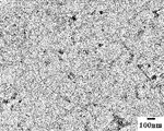
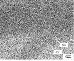
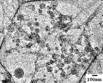
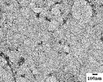
- Low magnification TEM image of the recovered BNNT product A low-magnification TEM image of a sample from which the solvent was removed from the BNNT dispersion of Example 1. High-resolution TEM image of the sample from which the solvent was removed from the BNNT dispersion liquid of Example 1. A high-resolution TEM image of a sample obtained by drying the BNNT dispersion liquid of Example 1 and then heat-treating it in the air at 500 ° C. for 1 hr. A low-magnification TEM image of a sample from which the solvent was removed from the BNNT dispersion of Example 2. A low-magnification TEM image of a sample from which the solvent was removed from the BNNT dispersion liquid of Comparative Example 1. A low-magnification TEM image of a sample from which the solvent was removed from the BNNT dispersion of Comparative Example 2.
- the method for producing boron nitride nanotubes according to the embodiment of the present invention will be described with reference to the drawings.
- the boron nitride nanotube may be abbreviated as BNNT.
- the post-synthesis product from which water has been removed that is, a raw material containing boron nitride nanotubes, a nonionic polymer dispersant having a sp3-binding CH group, and an organic solvent are mixed to obtain a suspension.
- a raw material containing boron nitride nanotubes, a nonionic polymer dispersant having a sp3-binding CH group, and an organic solvent are mixed to obtain a suspension.
- the product after synthesis is added to this solution, and the boron nitride nanotubes are uniformly coated with the polymer dispersant by ultrasonically dispersing them with a homogenizer or the like.
- the "product after synthesis" is not only the product in the state immediately after synthesis, but also after synthesizing BNNT and before the step according to the present invention. Including those with.
- the raw material containing the boron nitride nanotubes is not limited to the product as it is synthesized, but also includes the boron nitride nanotube product obtained by removing by-products contained in the product as it is synthesized to some extent by other treatment or the like. Therefore, in the following description, the "product after synthesis" includes all raw materials containing boron nitride nanotubes used in the manufacturing process of BNNT according to the present invention described later.
- the nonionic polymer dispersant having a sp3-binding CH group has a substituted glucose structure in which at least one of the substitutable hydroxyl groups at the 2, 3 and 6 positions is an alkyl ether as a repeating unit.
- Cellulous polymers such as ethyl cellulose, methyl cellulose, propyl cellulose, butyl cellulose, hydroxypropyl cellulose, acetyl cellulose, etc., which are polymers linked at the 1st and 4th positions, or at least one methylene group and at least one or more.
- Vinyl-based polymers such as polyvinyl butyral, polyvinylformal, polyvinylacetate, ethylene-vinyl acetate polymer, polystyrene, polyvinyl alcohol, polyacrylonitrile, polyvinylmethylketone, and polymethylmethacrylate, which are polymers having a substituted methylene group as a repeating unit. It is preferable to use it. This is because the ⁇ orbital symmetry of the boron nitride nanotube is low, so that the boron nitride nanotube and CH / ⁇ are more than the polymer that interacts with the boron nitride nanotube ⁇ / ⁇ like the polymer applied in Patent Document 1.
- Interacting polymers are more likely to bind to boron nitride nanotubes.
- the main chain of the nonionic polymer having a sp3-bonding CH group is more flexible than the sp2-binding main chain of the polymer applied in Patent Document 1, it is suitable for a small-diameter boron nitride nanotube. Easy to wrap. Therefore, in particular, it is considered that the small-diameter boron nitride nanotubes obtained in Patent Document 2 and Patent Document 3 can be easily coated by using a nonionic polymer dispersant having a sp3-bonding CH group. ..
- Carboxymethyl cellulose which is widely applied as a polymer dispersant for carbon nanotubes (CNTs), is an ionic polymer having a sp3-binding CH group, and an aqueous solvent is used.
- CMC Carboxymethyl cellulose
- this CMC is applied as a dispersant for BNNT having a small diameter, micelles are formed around BNNT, and BNNT is solubilized by encapsulating BNNT in the hydrophobic space formed by the micelles.
- the size of micelles follows the shape of the substance and is solubilized regardless of the shape, by-products other than BNNT are also solubilized. Therefore, it is considered that CMC is difficult to selectively solubilize only BNNT having a small diameter.
- BNNT in the case of a nonionic polymer having a sp3-binding CH group, since an organic solvent is used, micelles are not formed around BNNT. Therefore, due to the difference in shape and size between BNNT and impurities (by-products other than BNNT), the adsorptivity of the dispersant to each and the solubilization property thereof are different, and it is easy to separate BNNT and impurities. It is considered that BNNT can be selectively dispersed.
- Organic solvents include benzyl alcohol, methanol, ethanol, isopropyl alcohol, butanol, acetone, methyl ethyl ketone, diethyl ketone, methyl isobutyl ketone, ethyl acetate, butyl acetate, N-methylpyrrolidone, N.N-dimethylformamide, cyclohexanone, isophorone, tetrahydrofuran, 2-Methyltetranone, ethyl lactate, butyl lactate, ethylene glycol dimethyl ether and the like may be used.
- the mixture may be stirred with, for example, an ultrasonic homogenizer.
- stirring conditions after stirring under the predetermined stirring conditions, the separation step described later is performed, the SEM image of the supernatant and the residue is confirmed, and the setting is made according to the separability of the by-product and the destruction prevention effect of BNNT. Will be done.
- stirring is performed under a plurality of conditions, and from each image after separation, the amount of by-products is relatively small in the supernatant liquid, and the conditions in which the destruction / breakage of BNNT is inconspicuous and the amount of BNNT broken in the residue. Is set under conditions that make it inconspicuous.
- a frequency of 20 kHz, an ultrasonic amplitude of 40 to 80 ⁇ m, and a stirring time of about 20 to 40 minutes are preferable, the boron nitride nanotubes are not easily destroyed, and the boron nitride nanotubes are easily dispersed.
- a suspension can be obtained by the above operation.
- the composition of the suspension obtained by mixing the post-synthesis product that is, a raw material containing a boron nitride nanotube, a nonionic polymer dispersant having a sp3-bonding CH group, and an organic solvent, is as follows.
- the raw material containing the boron nitride nanotube may be 1 part by mass
- the nonionic polymer dispersant having a sp3-bonding CH group may be 1 to 2000 parts by mass
- the organic solvent may be 200 to 100,000 parts by mass.
- the lower limit of the amount of the dispersant added is set according to the separability of the by-product, for example, by performing the separation step described later, confirming the SEM image of the supernatant and the residue, and the like. For example, by changing the addition amount of the dispersant under a plurality of conditions, the amount of BNNT in the supernatant liquid is relatively large and the amount of BNNT in the residue is relatively large from each image after separation, or the amount of BNNT in the residue. It is set under conditions that do not stand out.
- the upper limit of the addition amount of the dispersant is, for example, as the light absorption characteristic of the dispersion liquid after the separation step described later is confirmed in the ultraviolet region, and from the relationship between the maximum absorption amount and the addition amount, the addition amount increases.
- the increase in the amount of light absorption is set under a condition where the amount of light absorption is substantially saturated.
- the range of the dispersant and the solvent is not more than the upper limit because it is efficient and economical, and it is preferable that the range is more than the lower limit because the dispersibility of BNNT is improved.
- the step of centrifuging the obtained suspension removes by-products.
- the by-product refers to BN fullerene, h-BN flakes, etc. having boron particles contained in the solution as a core.
- the conditions for centrifugation to separate these by-products are set according to the separability of the by-products by confirming the SEM image of the supernatant liquid and the residue after the separation step. For example, by changing multiple conditions (time, centrifugal force), the amount of by-products in the supernatant is relatively small from each image after separation, and the dispersant polymer (film covering the by-products entirely) in the residue. It is set under the condition that the amount of polymer) is large.
- the centrifugal acceleration may be 30,000 G or more
- the processing time may be 1 hour or more
- the liquid temperature may be 25 ° C.
- the process of centrifuging the last obtained suspension, removing by-products contained in the raw material, and obtaining a dispersion liquid containing boron nitride nanotubes will be described.
- the removal of by-products from the suspension may be carried out, for example, with a high-speed cooling centrifuge.
- a BNNT dispersion liquid in which BNNT coated with a nonionic polymer having a sp3-binding CH group is dispersed in an organic solvent can be obtained.
- BNNT BNNT dispersion liquid
- the organic solvent is evaporated from the above-mentioned BNNT dispersion.
- BNNT is in a state of being coated with a solid polymer dispersant.
- the BNNT coated with the dispersant is thermally decomposed and removed by heating the BNNT to a temperature of 300 ° C. or higher and 900 ° C. or lower in the atmosphere. This makes it possible to purify the BNNT contained in the dispersion with high purity.
- the temperature is 300 ° C. or higher, the dispersant is sufficiently easily thermally decomposed, which is preferable.
- the temperature is 900 ° C.
- the BNNT can remain without burning disappearing, and if the temperature is lower than 650 ° C., the temperature is lower than the thermal oxidation treatment temperature of the boron particles. It is preferable because the boron nitride nanotubes are easily dispersed while avoiding sticking.
- a boron nitride nanotube dispersion used for evaluation was prepared by the following method.
- a small plasma apparatus (TekNan Install-15 manufactured by TEKNA Plasma Systems inc.) was used to synthesize a BNNT product containing by-products, that is, a raw material containing boron nitride nanotubes in the following manner.
- the inside of the reaction vessel was purged with argon gas.
- an argon gas flow velocity: 10 L / min
- a mixed gas of argon (30 L / min) and hydrogen 2.5 L / min
- FIG. 1 is a low magnification transmission electron microscope (TEM) image of the obtained product.
- the product has BNNT 101 and BN fullerene 102 and h-BN flakes 103.
- the BN fullerene 102 is a substance having a graphene structure in which B atoms and N atoms are alternately bonded, and has a spherical or oblong closed structure.
- the h-BN thin section 103 is a sheet-like substance made of crystalline h-BN. Boron particles (black contrast portion) are incorporated in the BN fullerene 102.
- another synthesizing method may be used as a method of synthesizing a product.
- Example 1 using the product after synthesis, each treatment was carried out as Example 1 by the following method. After mixing 25 mg of ethyl cellulose (EC) manufactured by Tokyo Chemical Industry Co., Ltd. as a dispersant and 20 cm 3 of benzyl alcohol as an organic solvent, 15 mg of the product synthesized above was added to this solution. That is, 1 part by mass of the synthetic product, that is, the raw material containing the boron nitride nanotube, 1.7 parts by mass of the nonionic polymer dispersant having a sp3-binding CH group, and 1333 parts by mass of the organic solvent. And said. The mixture was dispersed at room temperature with an ultrasonic homogenizer for 20 minutes. Subsequently, the mixture was centrifuged at a centrifugal acceleration of 30,000 G for 3 hours to remove by-products contained in the raw material, and a BNNT dispersion was obtained.
- EC ethyl cellulose
- FIG. 2 is a low-magnification TEM image of the sample from which the solvent has been removed from the BNNT dispersion. It was confirmed that the BN fullerene and h-BN flakes contained in the synthetic product shown in FIG. 1 were removed. From this, it was found that the proportion of by-products having a small strengthening effect such as boron nitride fullerene and h-BN flakes was reduced.
- FIG. 3 is a high-resolution TEM image of the sample of FIG. 2.
- the surface of BNNT301 was covered with an amorphous substance 302 which seems to be ethyl cellulose.
- Patent Document 2 requires a step of oxidizing air to air at a temperature in the range of 650 ° C. to 850 ° C. as a thermal oxidation treatment, but the step was not performed in Example 1.
- FIG. 4 is a high-resolution TEM image of a sample prepared by adding BNNT heat-treated in the atmosphere to isopropyl alcohol and dropping an ultrasonically treated BNNT dispersion onto a copper grid coated with a carbon film.
- Example 2 BNNT was obtained in the same manner as in Example 1 except that the dispersant was polyvinyl butyral (PVB), which is a vinyl polymer.
- FIG. 5 is a low-magnification TEM image of the sample from which the solvent has been removed from the BNNT dispersion. Similar to Example 1, it was found that the proportion of by-products having a small strengthening effect such as boron nitride fullerene and h-BN flakes was reduced.
- the dispersant was poly [m-phenylene vinylene-co- (2,5-dioctoxy-p-phenylene vinylene)] (PmPV), which is a nonionic polymer having a sp2-binding CH group.
- BNNT was obtained in the same manner as in Example 1 except that.
- FIG. 6 is a low-magnification TEM image of the sample from which the solvent has been removed from the BNNT dispersion. It was found that the proportion of small by-products such as boron nitride fullerene and h-BN flakes was reduced.
- BNNT was obtained in the same manner as in Example 1 except that the dispersant was CMC (carboxymethyl cellulose), which is an ionic polymer having a sp3-binding CH group, and water was used as a solvent. ..
- FIG. 7 is a low-magnification TEM image of the sample from which the solvent has been removed from the BNNT dispersion. It was found that a large number of by-products having a small strengthening effect such as boron nitride fullerene and h-BN flakes remained.
- Example 1 Example 2, Comparative Example 1, and Comparative Example 2, the amount of residual by-products (BN fullerene and h-BN flakes) is determined from the TEM image of the sample from which the solvent has been removed from the BNNT dispersion.
- Example 2 had the smallest amount, followed by Example 1 and Comparative Example 1 with the smallest amount, and Comparative Example 2 had the largest amount of by-products. This is because in Comparative Example 2, since the dispersant was an ionic polymer and water was used as the solvent, micelles were generated around the BNNT as described above, and relatively coarse by-products (BN fullerene and h-) were generated.
- the dispersion liquid of Comparative Example 1 has a sp2-binding main chain, it is more rigid than EC and PVB having an sp3-binding main chain, and is particularly difficult to wrap around a small-diameter BNNT and has poor dispersibility. It is thought that it was. From these results, when the dispersant of the present invention was applied, the remaining amount of by-products was smaller (the purity of BNNT was higher) and the yield of BNNT was higher than that when the dispersant of the comparative example was applied. Was found to be higher.
- the present invention is not limited to these examples, and various modifications can be made within the scope of the invention described in the claims, and it goes without saying that they are also included in the scope of the present invention. not.
- the conditions for ultrasonic waves and centrifugation used in the production of the dispersion liquid may be appropriately selected according to the mixing ratio of the masses of BNNT, the dispersant, and the solvent.
Landscapes
- Chemical & Material Sciences (AREA)
- Organic Chemistry (AREA)
- Inorganic Chemistry (AREA)
- Engineering & Computer Science (AREA)
- Nanotechnology (AREA)
- Physics & Mathematics (AREA)
- General Physics & Mathematics (AREA)
- Manufacturing & Machinery (AREA)
- Crystallography & Structural Chemistry (AREA)
- Condensed Matter Physics & Semiconductors (AREA)
- Carbon And Carbon Compounds (AREA)
- Emulsifying, Dispersing, Foam-Producing Or Wetting Agents (AREA)
- Inorganic Fibers (AREA)
Abstract
Description
である。
なお、本発明において、「合成後の生成物」とは、合成した直後の状態の生成物のみではなく、BNNTを合成した後であって、本発明にかかる工程よりも前に、他の処理を施したものを含む。すなわち、窒化ホウ素ナノチューブを含む原料としては、合成したままの生成物に限らず、合成したままの生成物に含まれる副生成物を他の処理等によりある程度除去した窒化ホウ素ナノチューブ生成物も含む。したがって、以下の説明において、「合成後の生成物」は、後述する本発明にかかるBNNTの製造工程に用いられる窒化ホウ素ナノチューブを含む原料を全て含むものとする。
なお、カーボンナノチューブ(CNT)のポリマー分散剤として広く適用されるカルボキシメチルセルロース(CMC)は、sp3結合性のCH基を有するイオン性ポリマーであり、水系溶媒が用いられる。このCMCを細径のBNNTの分散剤として適用した場合、BNNT周辺にミセルが形成され、ミセルによって形成される疎水性空間にBNNTが内包されることでBNNTが可溶化する。しかし、ミセルのサイズが物質の形状に追従し、形状によらず可溶化するため、BNNT以外の副生成物も可溶化する。このため、CMCは、細径のBNNTのみを選択的に可溶化させにくいと考えられる。一方、sp3結合性のCH基を有する非イオン性ポリマーの場合、有機溶媒を使用するため、BNNT周辺にミセルは形成されない。このため、BNNTと不純物(BNNT以外の副生成物)の形状やサイズの差異により、それぞれへの分散剤の吸着性および、これらの可溶化性に差異が生じ、BNNTと不純物を分離しやすく、選択的にBNNTを分散できると考えられる。
まず、評価に用いられる窒化ホウ素ナノチューブ分散液を下記の方法で準備した。まず、小型プラズマ装置(TEKNA Plasma Systems inc.製 TekNanо―15)を用い、以下の要領で副生成物を含有するBNNT生成物、すなわち窒化ホウ素ナノチューブを含む原料を合成した。始めに、反応容器内をアルゴンガスでパージした。次に、中央領域にアルゴンガス(流速:10L/min)を流し、アルゴン(30L/min)と水素(2.5L/min)の混合ガスを流すことにより、プラズマを閉じ込める管の外周にシースガスを流す。窒素ガスは、トーチノズル(10L/min)と反応容器を取り囲むポーラスウォール(47L/min)の両方を通して流される。プラズマ着火から数分後、反応容器とサイクロンの間に設置した熱電対の温度が一定になった時点で、素原料のh-BN粉末(平均粒径:5μm)をプラズマトーチの上部に設置したフィーダから、アルゴン(2.5L/min)をキャリアガスとして連続供給した。供給速度は0.5g/min、運転時間は2hr、反応チャンバ内圧力は1atmとした。合成が終了した後、装置を分解して、プラズマトーチ、リアクタ、サイクロン及びフィルター部に付着した生成物を回収した。
また、実施例1、実施例2、比較例1、比較例2について、それぞれ、以下の式にて、分散したBNNTの収率を求めた。
収率(%)={([合成後の生成物質量]―[遠心分離後の残渣の質量])/[合成後の生成物質量]}×100
その結果、実施例1(55%)>実施例2(51%)>比較例1(32%)>比較例2(20%)の順で、収率が高いことが分かった。
比較例1の分散液は、sp2結合性の主鎖を持つため、sp3結合性の主鎖を有するEC、PVBと比較して剛直であり、特に細径のBNNTに巻き付きにくく、分散性が劣ったものと考えられる。
これらの結果より、本発明の分散剤を適用した場合、比較例の分散剤を適用した場合に比べて、副生成物の残量が少なく(BNNTの純度が高く)、かつ、BNNTの収率が高くなることがわかった。
102・・・BNフラーレン
103・・・h-BN薄片
302・・・エチルセルロース
Claims (2)
- 窒化ホウ素ナノチューブを含む原料と、
sp3結合性のCH基を有する非イオン性ポリマー分散剤と、
有機溶媒と、を混合し、懸濁液を得る工程と、
得られた懸濁液を遠心分離し、原料に含まれる副生成物を除去し、窒化ホウ素ナノチューブを含む分散液を得る工程と、
を有することを特徴とする窒化ホウ素ナノチューブの製造方法。 - 前記ポリマー分散剤が、セルロース系ポリマー又はビニル系ポリマーを含むことを特徴とする請求項1に記載の窒化ホウ素ナノチューブの製造方法。
Priority Applications (5)
| Application Number | Priority Date | Filing Date | Title |
|---|---|---|---|
| JP2022562199A JP7276625B2 (ja) | 2020-11-16 | 2021-11-12 | 窒化ホウ素ナノチューブの製造方法 |
| US18/036,973 US20230406705A1 (en) | 2020-11-16 | 2021-11-12 | Method for producing boron nitride nanotubes |
| CA3199050A CA3199050A1 (en) | 2020-11-16 | 2021-11-12 | Method for producing boron nitride nanotubes |
| CN202180077063.5A CN117015512B (zh) | 2020-11-16 | 2021-11-12 | 氮化硼纳米管的制造方法 |
| JP2022195650A JP7632439B2 (ja) | 2020-11-16 | 2022-12-07 | 窒化ホウ素ナノチューブ製造用窒化ホウ素ナノチューブ混合液 |
Applications Claiming Priority (2)
| Application Number | Priority Date | Filing Date | Title |
|---|---|---|---|
| JP2020190291 | 2020-11-16 | ||
| JP2020-190291 | 2020-11-16 |
Publications (1)
| Publication Number | Publication Date |
|---|---|
| WO2022102741A1 true WO2022102741A1 (ja) | 2022-05-19 |
Family
ID=81602378
Family Applications (1)
| Application Number | Title | Priority Date | Filing Date |
|---|---|---|---|
| PCT/JP2021/041701 Ceased WO2022102741A1 (ja) | 2020-11-16 | 2021-11-12 | 窒化ホウ素ナノチューブの製造方法 |
Country Status (5)
| Country | Link |
|---|---|
| US (1) | US20230406705A1 (ja) |
| JP (2) | JP7276625B2 (ja) |
| CN (1) | CN117015512B (ja) |
| CA (1) | CA3199050A1 (ja) |
| WO (1) | WO2022102741A1 (ja) |
Families Citing this family (1)
| Publication number | Priority date | Publication date | Assignee | Title |
|---|---|---|---|---|
| JP7073988B2 (ja) * | 2018-08-31 | 2022-05-24 | 株式会社三洋物産 | 遊技機 |
Citations (3)
| Publication number | Priority date | Publication date | Assignee | Title |
|---|---|---|---|---|
| JP2004161546A (ja) * | 2002-11-13 | 2004-06-10 | National Institute For Materials Science | 窒化ホウ素前駆物質の形成方法と窒化ホウ素前駆物質を利用した窒化ホウ素ナノチューブの製造方法 |
| JP2011102203A (ja) * | 2009-11-10 | 2011-05-26 | Teijin Ltd | 窒化ホウ素ナノチューブ誘導体、その分散液、及び該窒化ホウ素ナノチューブ誘導体の製造方法 |
| JP2020514230A (ja) * | 2016-11-29 | 2020-05-21 | ビイエヌエヌティ・エルエルシイ | 窒化ホウ素ナノチューブの精製方法 |
Family Cites Families (4)
| Publication number | Priority date | Publication date | Assignee | Title |
|---|---|---|---|---|
| US7956108B2 (en) * | 2003-05-30 | 2011-06-07 | The Provost, Fellows And Scholars Of The College Of The Holy And Undivided Trinity Of Queen Elizabeth, Near Dublin | Product |
| JP4670100B2 (ja) * | 2006-03-01 | 2011-04-13 | 独立行政法人物質・材料研究機構 | 窒化ホウ素ナノチューブの精製方法 |
| KR101429559B1 (ko) * | 2012-02-23 | 2014-08-14 | 한국원자력연구원 | 질화붕소나노튜브의 정제 및 표면처리 방법 |
| KR102299406B1 (ko) * | 2019-08-16 | 2021-09-08 | 한국과학기술연구원 | 금속 불순물을 이용한 자가 활성화가 가능한 전기화학적 이산화탄소 환원 촉매 전극 및 그 제조방법 |
-
2021
- 2021-11-12 CA CA3199050A patent/CA3199050A1/en active Pending
- 2021-11-12 JP JP2022562199A patent/JP7276625B2/ja active Active
- 2021-11-12 WO PCT/JP2021/041701 patent/WO2022102741A1/ja not_active Ceased
- 2021-11-12 CN CN202180077063.5A patent/CN117015512B/zh active Active
- 2021-11-12 US US18/036,973 patent/US20230406705A1/en active Pending
-
2022
- 2022-12-07 JP JP2022195650A patent/JP7632439B2/ja active Active
Patent Citations (3)
| Publication number | Priority date | Publication date | Assignee | Title |
|---|---|---|---|---|
| JP2004161546A (ja) * | 2002-11-13 | 2004-06-10 | National Institute For Materials Science | 窒化ホウ素前駆物質の形成方法と窒化ホウ素前駆物質を利用した窒化ホウ素ナノチューブの製造方法 |
| JP2011102203A (ja) * | 2009-11-10 | 2011-05-26 | Teijin Ltd | 窒化ホウ素ナノチューブ誘導体、その分散液、及び該窒化ホウ素ナノチューブ誘導体の製造方法 |
| JP2020514230A (ja) * | 2016-11-29 | 2020-05-21 | ビイエヌエヌティ・エルエルシイ | 窒化ホウ素ナノチューブの精製方法 |
Also Published As
| Publication number | Publication date |
|---|---|
| CN117015512B (zh) | 2025-11-21 |
| JP7276625B2 (ja) | 2023-05-18 |
| CA3199050A1 (en) | 2022-05-19 |
| US20230406705A1 (en) | 2023-12-21 |
| JPWO2022102741A1 (ja) | 2022-05-19 |
| CN117015512A (zh) | 2023-11-07 |
| JP7632439B2 (ja) | 2025-02-19 |
| JP2023024853A (ja) | 2023-02-17 |
Similar Documents
| Publication | Publication Date | Title |
|---|---|---|
| JP6359081B2 (ja) | 窒化ホウ素ナノチューブ及びその製造方法 | |
| JP2590442B2 (ja) | カーボンナノチューブの分離精製方法 | |
| US7842271B2 (en) | Mass production of carbon nanostructures | |
| CN100368287C (zh) | 单壁碳质毫微管有助于其溶剂化的化学衍生化以及经衍生化毫微管的用途 | |
| JP6380687B2 (ja) | カーボンナノチューブ分散液の製造方法 | |
| JP5477702B2 (ja) | 窒化ホウ素ナノチューブ誘導体、その分散液、及び該窒化ホウ素ナノチューブ誘導体の製造方法 | |
| Nair et al. | Radio frequency plasma mediated dry functionalization of multiwall carbon nanotube | |
| JPWO2018180901A1 (ja) | 繊維状炭素ナノ構造体分散液及びその製造方法、並びに繊維状炭素ナノ構造体 | |
| US20060073275A1 (en) | Process and apparatus for producing single-walled carbon nanotube | |
| JP7632439B2 (ja) | 窒化ホウ素ナノチューブ製造用窒化ホウ素ナノチューブ混合液 | |
| KR102689749B1 (ko) | 섬유상 탄소 나노 구조체 분산액 | |
| JP4567319B2 (ja) | カーボンナノチューブの製造方法 | |
| CN108190860B (zh) | 一种微波制备单壁碳纳米管的方法 | |
| WO2016043664A1 (en) | Method of functionalizing surfaces of carbon nanomaterials | |
| EP3587347A1 (en) | Method for producing carbon nanohorn aggregates | |
| KR20190071293A (ko) | 마이크로웨이브를 이용한 그래핀의 제조방법 | |
| CN118306980B (zh) | 一种连续批量纯化单壁碳纳米管的方法及其系统 | |
| CN115784203B (zh) | 一类基于富勒烯分子晶体的长程有序多孔碳晶体材料及其规模化制备方法 | |
| Ge et al. | Study on the controllable scale-up growth of vertically-aligned carbon nanotube arrays | |
| Joy et al. | Low temperature synthesis of carbon nanostructure and effect of temperatures on the growth of amorphous carbon nanostructure | |
| CN112408363A (zh) | 一种碳纳米管的原位制备方法 | |
| Ramirez-Hernandez et al. | FABRICATION OF CNTS BY TOLUENE DECOMPOSITION IN A NEW REACTOR BASED ON AN ATMOSPHERIC PRESSURE PLASMA JET COUPLED TO A CVD SYSTEM | |
| WO2007097339A1 (ja) | 炭素系物質、単環式炭化水素化合物又は多環式炭化水素化合物の製造方法及び製造装置 | |
| KR20020067187A (ko) | 단층 탄소 나노튜브 정제 방법 및 이에 이용되는 열처리장비 | |
| NANOCARBONS | University of Sussex, Brighton, BNI 9QJ, UK |
Legal Events
| Date | Code | Title | Description |
|---|---|---|---|
| 121 | Ep: the epo has been informed by wipo that ep was designated in this application |
Ref document number: 21891986 Country of ref document: EP Kind code of ref document: A1 |
|
| ENP | Entry into the national phase |
Ref document number: 2022562199 Country of ref document: JP Kind code of ref document: A |
|
| ENP | Entry into the national phase |
Ref document number: 3199050 Country of ref document: CA |
|
| WWE | Wipo information: entry into national phase |
Ref document number: 202180077063.5 Country of ref document: CN |
|
| NENP | Non-entry into the national phase |
Ref country code: DE |
|
| 122 | Ep: pct application non-entry in european phase |
Ref document number: 21891986 Country of ref document: EP Kind code of ref document: A1 |