WO2022102560A1 - 端子台 - Google Patents
端子台 Download PDFInfo
- Publication number
- WO2022102560A1 WO2022102560A1 PCT/JP2021/040935 JP2021040935W WO2022102560A1 WO 2022102560 A1 WO2022102560 A1 WO 2022102560A1 JP 2021040935 W JP2021040935 W JP 2021040935W WO 2022102560 A1 WO2022102560 A1 WO 2022102560A1
- Authority
- WO
- WIPO (PCT)
- Prior art keywords
- terminal
- shield shell
- holding cylinder
- terminal block
- fixing
- Prior art date
- Legal status (The legal status is an assumption and is not a legal conclusion. Google has not performed a legal analysis and makes no representation as to the accuracy of the status listed.)
- Ceased
Links
Images


Classifications
-
- H—ELECTRICITY
- H01—ELECTRIC ELEMENTS
- H01R—ELECTRICALLY-CONDUCTIVE CONNECTIONS; STRUCTURAL ASSOCIATIONS OF A PLURALITY OF MUTUALLY-INSULATED ELECTRICAL CONNECTING ELEMENTS; COUPLING DEVICES; CURRENT COLLECTORS
- H01R13/00—Details of coupling devices of the kinds covered by groups H01R12/70 or H01R24/00 - H01R33/00
- H01R13/46—Bases; Cases
- H01R13/533—Bases, cases made for use in extreme conditions, e.g. high temperature, radiation, vibration, corrosive environment, pressure
-
- H—ELECTRICITY
- H05—ELECTRIC TECHNIQUES NOT OTHERWISE PROVIDED FOR
- H05K—PRINTED CIRCUITS; CASINGS OR CONSTRUCTIONAL DETAILS OF ELECTRIC APPARATUS; MANUFACTURE OF ASSEMBLAGES OF ELECTRICAL COMPONENTS
- H05K7/00—Constructional details common to different types of electric apparatus
- H05K7/20—Modifications to facilitate cooling, ventilating, or heating
- H05K7/2039—Modifications to facilitate cooling, ventilating, or heating characterised by the heat transfer by conduction from the heat generating element to a dissipating body
- H05K7/20436—Inner thermal coupling elements in heat dissipating housings, e.g. protrusions or depressions integrally formed in the housing
-
- H—ELECTRICITY
- H01—ELECTRIC ELEMENTS
- H01R—ELECTRICALLY-CONDUCTIVE CONNECTIONS; STRUCTURAL ASSOCIATIONS OF A PLURALITY OF MUTUALLY-INSULATED ELECTRICAL CONNECTING ELEMENTS; COUPLING DEVICES; CURRENT COLLECTORS
- H01R11/00—Individual connecting elements providing two or more spaced connecting locations for conductive members which are, or may be, thereby interconnected, e.g. end pieces for wires or cables supported by the wire or cable and having means for facilitating electrical connection to some other wire, terminal, or conductive member, blocks of binding posts
- H01R11/03—Individual connecting elements providing two or more spaced connecting locations for conductive members which are, or may be, thereby interconnected, e.g. end pieces for wires or cables supported by the wire or cable and having means for facilitating electrical connection to some other wire, terminal, or conductive member, blocks of binding posts characterised by the relationship between the connecting locations
- H01R11/05—Individual connecting elements providing two or more spaced connecting locations for conductive members which are, or may be, thereby interconnected, e.g. end pieces for wires or cables supported by the wire or cable and having means for facilitating electrical connection to some other wire, terminal, or conductive member, blocks of binding posts characterised by the relationship between the connecting locations the connecting locations having different types of direct connections
-
- H—ELECTRICITY
- H01—ELECTRIC ELEMENTS
- H01R—ELECTRICALLY-CONDUCTIVE CONNECTIONS; STRUCTURAL ASSOCIATIONS OF A PLURALITY OF MUTUALLY-INSULATED ELECTRICAL CONNECTING ELEMENTS; COUPLING DEVICES; CURRENT COLLECTORS
- H01R13/00—Details of coupling devices of the kinds covered by groups H01R12/70 or H01R24/00 - H01R33/00
- H01R13/40—Securing contact members in or to a base or case; Insulating of contact members
- H01R13/405—Securing in non-demountable manner, e.g. moulding, riveting
-
- H—ELECTRICITY
- H01—ELECTRIC ELEMENTS
- H01R—ELECTRICALLY-CONDUCTIVE CONNECTIONS; STRUCTURAL ASSOCIATIONS OF A PLURALITY OF MUTUALLY-INSULATED ELECTRICAL CONNECTING ELEMENTS; COUPLING DEVICES; CURRENT COLLECTORS
- H01R13/00—Details of coupling devices of the kinds covered by groups H01R12/70 or H01R24/00 - H01R33/00
- H01R13/46—Bases; Cases
- H01R13/53—Bases or cases for heavy duty; Bases or cases for high voltage with means for preventing corona or arcing
-
- H—ELECTRICITY
- H05—ELECTRIC TECHNIQUES NOT OTHERWISE PROVIDED FOR
- H05K—PRINTED CIRCUITS; CASINGS OR CONSTRUCTIONAL DETAILS OF ELECTRIC APPARATUS; MANUFACTURE OF ASSEMBLAGES OF ELECTRICAL COMPONENTS
- H05K9/00—Screening of apparatus or components against electric or magnetic fields
- H05K9/0007—Casings
- H05K9/0018—Casings with provisions to reduce aperture leakages in walls, e.g. terminals, connectors, cables
-
- H—ELECTRICITY
- H05—ELECTRIC TECHNIQUES NOT OTHERWISE PROVIDED FOR
- H05K—PRINTED CIRCUITS; CASINGS OR CONSTRUCTIONAL DETAILS OF ELECTRIC APPARATUS; MANUFACTURE OF ASSEMBLAGES OF ELECTRICAL COMPONENTS
- H05K9/00—Screening of apparatus or components against electric or magnetic fields
- H05K9/0007—Casings
- H05K9/002—Casings with localised screening
- H05K9/0022—Casings with localised screening of components mounted on printed circuit boards [PCB]
- H05K9/0024—Shield cases mounted on a PCB, e.g. cans or caps or conformal shields
-
- H—ELECTRICITY
- H01—ELECTRIC ELEMENTS
- H01R—ELECTRICALLY-CONDUCTIVE CONNECTIONS; STRUCTURAL ASSOCIATIONS OF A PLURALITY OF MUTUALLY-INSULATED ELECTRICAL CONNECTING ELEMENTS; COUPLING DEVICES; CURRENT COLLECTORS
- H01R2201/00—Connectors or connections adapted for particular applications
- H01R2201/26—Connectors or connections adapted for particular applications for vehicles
Definitions
- This disclosure relates to a terminal block.
- Patent Document 1 discloses a terminal block having a shielding function including a shield shell that shields the periphery of an insulating housing in which terminals are housed and arranged.
- the terminal block of the present disclosure includes a terminal having a connection portion connected to a mating terminal on the tip side and a fixing portion on the base end side, a tubular hood portion surrounding the connection portion of the terminal, and the above-mentioned terminal block.
- a holding cylinder portion that surrounds the fixing portion of the terminal, a metal shield shell having a contact portion that thermally contacts an external heat dissipation target, and the fixing portion of the terminal and the holding cylinder portion of the shield shell. It is provided with a filling resin portion that fills the space between the facing surfaces of the terminal and integrally fixes the fixing portion of the terminal to the holding cylinder portion of the shield shell.
- the terminal block of the present disclosure it is possible to improve the heat dissipation of the terminal while reducing the size with a small number of parts.
- FIG. 1 is an overall perspective view showing a state in which the terminal block according to the first embodiment is attached to an external metal housing to be dissipated.
- FIG. 2 is a plan view of FIG.
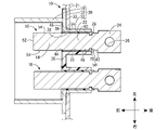
- FIG. 3 is a sectional view taken along line III-III in FIG.
- FIG. 4 is a sectional view taken along line IV-IV in FIG.
- FIG. 5 is a sectional view taken along line VV in FIG.
- FIG. 6 is a sectional view taken along line VI-VI in FIG.
- the terminal block of this disclosure is (1) A terminal having a connection portion connected to the mating terminal on the tip side and a fixing portion on the base end side, a tubular hood portion surrounding the connection portion of the terminal, and the fixing of the terminal.
- a holding cylinder portion that surrounds the periphery of the portion, a metal shield shell having a contact portion that is in thermal contact with an external heat dissipation target, and a facing surface between the fixing portion of the terminal and the holding cylinder portion of the shield shell. It is provided with a filling resin portion for filling a space and integrally fixing the fixing portion of the terminal to the holding cylinder portion of the shield shell.
- the shield shell and the terminal are integrated by a filling resin portion that fills the space between the fixed portion of the terminal and the facing surface of the holding cylinder portion of the shield shell. Therefore, the fixed structure and the insulating structure between the shield shell and the terminal can be simplified, and the entire terminal block can be miniaturized. Moreover, since the space between the fixed part of the terminal and the holding cylinder part of the shield shell is filled without a gap by the filling resin part, the heat generated in the terminal by energization does not go through the air layer, and the shield shell efficiently. Heat is transferred to the holding cylinder.
- the contact portion provided on the metal shield shell thermally contacts the external heat dissipation target, so that the heat generated in the terminal is transferred to the metal of the in-vehicle device through the filling resin portion and the metal shield shell. Efficiently transfers heat to an external heat dissipation target such as a manufacturing housing.
- an external heat dissipation target such as a manufacturing housing.
- the filled resin portion has a flange portion that protrudes from the first opening on the hood portion side of the holding cylinder portion and extends over the bottom surface of the hood portion.
- the filled resin portion has a flange portion that protrudes from the first opening on the hood portion side of the holding cylinder portion and covers the bottom surface of the hood portion. Therefore, by appropriately adjusting the size of the flange portion, it is possible to advantageously improve the adhesiveness of the filled resin portion to the shield shell while ensuring the creepage distance between the terminal and the metal shield shell with a high degree of freedom in design. can.
- the flange portion covers the space between the facing surfaces of the filling resin portion and the holding cylinder portion and the bottom surface of the flange portion and the hood portion is integrated, the space between the facing surfaces of the filling resin portion and the holding cylinder portion is formed.
- the occurrence of defects such as a decrease in heat transfer due to peeling is advantageously suppressed or prevented.
- the filled resin portion has a protruding portion that protrudes from the second opening on the side opposite to the hood portion side of the holding cylinder portion and is exposed to the outside.
- the filled resin portion has a protruding portion that protrudes from the second opening of the holding cylinder portion and is exposed to the outside. Therefore, by appropriately adjusting the length of the protruding portion, it is possible to secure the creepage distance between the holding cylinder portion of the shield shell and the member on the in-vehicle device side with a high degree of freedom in design. Further, even if water droplets adhere to the vicinity of the second opening, it is possible to prevent the occurrence of problems such as the water droplets entering and staying in the holding cylinder portion.
- the fixing portion of the terminal is provided with a concave portion that opens to the outer surface, and the filling resin portion has an engaging convex portion that fills the concave portion. Since the engaging convex portion of the filling resin portion is provided in the concave portion that opens on the outer surface of the fixing portion of the terminal, the terminal and the filling resin portion can be separated even when an insertion / removal force is applied to the terminal. It can be suppressed or blocked in an advantageous manner.
- connection portion has a flat plate shape extending in a rectangular cross section in the longitudinal direction of the terminal, and at least on the tip end side of the connection portion, the front end surface, both side surfaces, the upper surface and the lower surface of the connection portion are formed. It is preferable that the filled resin portion is not covered. Since the tip surface, both side surfaces, the upper surface and the lower surface of the connection portion are not covered with the filling resin portion at least on the tip side of the connection portion, the shield shell and the terminal are arranged in the mold to inject the filling resin portion. When molding, the terminals can be stably held by the mold.
- the positioning property of the terminal with respect to the shield shell is improved, and the gap dimension between the fixed portion of the terminal and the facing surface of the holding cylinder portion of the shield shell can be made as small as possible.
- the wall thickness of the filling resin portion of the portion filling the gap between the fixing portion of the terminal and the facing surface of the holding cylinder portion of the shield shell can be reduced to the elastic limit, and the filling resin portion from the terminal can be reduced. It is possible to further advantageously improve the heat transfer property to the shield shell via the shield shell.
- the wall thickness dimension of the filled resin portion arranged between the fixing portion of the terminal and the facing surface of the holding cylinder portion of the shield shell is 1.5 mm or less. Since the wall thickness of the filled resin part arranged between the fixed part of the terminal and the facing surface of the holding cylinder part of the shield shell is 1.5 mm or less, the heat transfer property from the terminal to the shield shell via the filling resin part is improved. It can be improved more advantageously.
- the shield shell has a fixing protrusion that spreads like a flange around the hood portion, and the contact portion of the shield shell is formed by a surface on which the fixing protrusion is overlapped with the heat radiation target. It is preferably configured.
- a contact part of the shield shell can be provided by using a projecting piece for fixing to an external heat dissipation target provided on the shield shell, and the contact part can be provided with a small number of parts to achieve both miniaturization and heat dissipation. Can be planned.
- the terminal block 10 of the first embodiment of the present disclosure will be described with reference to FIGS. 1 to 6.
- the terminal block 10 has a pair of terminals 16 and 16 having a connection portion 14 connected to the mating terminal 12 on the tip side, and a square cylindrical hood surrounding the connection portion 14 of the terminal 16. It includes a shield shell 20 having a portion 18.
- the terminal block 10 is used by being attached to, for example, a metal housing 21 of an inverter which is an external heat dissipation target.
- the terminal block 10 can be arranged in any direction, but in the following, the vertical direction, the horizontal direction, and the front-rear direction will be described with reference to the vertical direction, the left-right direction, and the front-back direction shown in the figure. Further, for a plurality of the same members, a reference numeral may be added to only a part of the members, and the reference numeral may be omitted for other members. Further, the remote terminal 12 is shown only in FIG. 3 and is shown by a virtual line for easy understanding.
- the terminal 16 has a flat plate shape.
- a metal material such as copper, a copper alloy, aluminum, an aluminum alloy, or stainless steel can be appropriately used.
- the terminal 16 may be surface-treated such as silver-plated, tin-plated, or aluminum-plated depending on the type of the constituent metal and the usage environment. For example, a metal plate having excellent conductivity is press-punched. Can be formed by.
- the terminal 16 has a connecting portion 14 having a flat plate shape extending in a rectangular cross section in the longitudinal direction (front-back direction in FIGS. 3 and 6) of the terminal 16 on the distal end side (front side in FIG. 3).
- the terminal 16 has a fixing portion 22 continuously provided at the rear end of the connecting portion 14 on the base end side (rear side in FIG. 3).
- the fixing portion 22 has a flat plate shape extending in a rectangular cross section in the longitudinal direction of the terminal 16.
- the terminal 16 is formed with a fastening portion 24 having a rectangular flat plate shape continuously at the rear end of the fixing portion 22 on the base end side (rear end side in FIG. 3) of the fixing portion 22.
- the fastening portion 24 has a bolt insertion hole 26 penetrated in the central portion and protrudes from the shield shell 20 to be exposed to the outside, so that the fastening portion 24 is fastened to a terminal of an in-vehicle device (not shown).
- the terminal 16 penetrates both ends of the fixing portion 22 on the fastening portion 24 side in the plate width direction on the outer surface, that is, in the plate thickness direction and faces outward in the plate width direction.
- a recess 28 is provided to open.
- the terminal 16 is formed with a fastening portion 24 having a rectangular flat plate shape continuously at the rear end of the fixing portion 22 on the base end side (rear end side in FIG. 3) of the fixing portion 22.
- the fastening portion 24 has a bolt insertion hole 26 penetrated in the central portion and protrudes from the shield shell 20 to be exposed to the outside, so that the fastening portion 24 is fastened to a terminal of an in-vehicle device (not shown).
- the terminal 16 is housed and used in the shield shell 20 of the terminal block 10.
- the shield shell 20 is made of a conductive metal.
- the shield shell 20 has a single hood portion 18 that accommodates the connection portions 14 of the pair of terminals 16 and 16 in parallel in the plate width direction on the front side, and surrounds the fixing portion 22 of the terminals 16 on the rear side. It has a pair of square tubular holding cylinders 30, 30 that are enclosed and separated in the plate width direction.
- the hood portion 18 is larger than the holding cylinder portion 30.
- the shield shell 20 spreads in a flange shape between the hood portion 18 and the pair of holding cylinder portions 30, 30 in a direction orthogonal to the longitudinal direction of the hood portion 18 and the pair of holding cylinder portions 30, 30.
- a fixing protrusion 32 is provided. As shown in FIG. 3, the fixing protrusion 32 is attached to a metal housing 21 which is an external heat dissipation target, and the fixing protrusion 32 is in close contact with the housing 21 to be in thermal contact.
- the contact portion 33 is configured by the portion to be formed. That is, the shield shell 20 has a fixing protrusion 32 that spreads like a flange around the hood portion 18, and the contact portion 33 of the shield shell 20 is superposed on the housing 21 of the fixing protrusion 32.
- an insertion hole 34 through which the pair of holding cylinders 30 and 30 are inserted is formed in the front surface of the housing 21.
- the fixing protrusion 32 is provided with a pair of communication holes 35, 35 that communicate the inside of the pair of holding cylinders 30, 30 with the hood portion 18, and covers the entire bottom wall of the holding cylinder 30.
- a communication hole 35 is formed over the entire area. As shown in FIG. 3, the communication hole 35 is formed slightly above the bottom surface 36 of the hood portion 18.
- ⁇ Filled resin part 40> As shown in FIGS. 3 and 6, a synthetic resin is filled between the facing surfaces 38 and 38 between the fixing portion 22 of the terminal 16 and the holding cylinder portion 30 of the shield shell 20 to form the filling resin portion 40. There is.
- the fixing portion 22 of the terminal 16 is integrally fixed to the holding cylinder portion 30 of the shield shell 20 by the filling resin portion 40.
- the wall thickness dimension of the filling resin portion 40 arranged between the facing surfaces 38 and 38 of the fixing portion 22 of the terminal 16 and the holding cylinder portion 30 of the shield shell 20: t (see FIG. 3) is 1. It is set to 5 mm or less. In this embodiment, it is 1.5 mm.
- the filling resin portion 40 is also filled in a pair of recesses 28, 28 provided at the rear end of the fixing portion 22 of the terminal 16, and the engaging convex portion for filling the recess 28 is also filled. It has a part 42. As a result, even when an insertion / extraction force is applied to the terminal 16, the separation between the terminal 16 and the filling resin portion 40 can be advantageously suppressed or prevented. Further, as shown in FIGS.
- the filling resin portion 40 has a flange portion 46 that protrudes from the first opening 44 on the hood portion 18 side of the holding cylinder portion 30 and extends over the bottom surface 36 of the hood portion 18.
- the filling resin portion 40 has a protruding portion 50 that protrudes from the second opening 48 on the side opposite to the hood portion 18 side of the holding cylinder portion 30 and is exposed to the outside.
- connection portion 14 on the tip end side of the connection portion 14 of the terminal 16, the tip surface 52, both side surfaces 54, 54, the upper surface 56, and the lower surface 58 of the connection portion 14 are formed by the filling resin portion 40. It is not covered and the connection portion 14 is exposed.
- a single shield shell 20 formed in a predetermined shape and a pair of terminals 16 and 16 are prepared.
- the terminal block 10 is manufactured by using, for example, two molds (not shown). More specifically, the two molds consist of a mold arranged in the front and a mold arranged in the rear.
- the pair of terminals 16 and 16 are inserted into the pair of communication holes 35 and 35 of the single shield shell 20. In this state, the two molds are arranged so that the pair of terminals 16 and 16 are in predetermined positions with respect to the single shield shell 20.
- the portion of the single shield shell 20 and the pair of terminals 16 and 16 that is not covered by the filling resin portion 40 is covered by the two molds. Then, the terminal block 10 is completed by injecting and filling the gap formed by the two molds with the resin.
- the fixing portion 22 of the terminal 16 is integrally fixed to the holding cylinder portion 30 of the shield shell 20 by the filling resin portion 40.
- the fixed structure and the insulating structure between the terminal 16 and the shield shell 20 can be simplified, so that the entire terminal block 10 can be miniaturized.
- the space between the fixing portion 22 of the terminal 16 and the facing surfaces 38, 38 of the holding cylinder portion 30 of the shield shell 20 is filled without a gap by the filling resin portion 40. Therefore, even when heat is generated in the terminal 16 due to energization, heat is efficiently dissipated to the holding cylinder portion 30 of the shield shell 20 without passing through the air layer.
- the contact portion 33 provided on the shield shell 20 is in thermal contact with the housing 21 which is an external heat dissipation target.
- the heat generated in the terminal 16 can be efficiently dissipated to an external heat dissipation target such as the housing 21 via the filling resin portion 40 and the shield shell 20. Therefore, the heat dissipation of the terminal 16 of the terminal block 10 is advantageously improved.
- connection portion 14 of the terminal 16 On the tip end side of the connection portion 14 of the terminal 16, the tip surface 52, both side surfaces 54, 54, the upper surface 56, and the lower surface 58 of the connection portion 14 are not covered by the filling resin portion 40, and the connection portion 14 is exposed. Therefore, the terminal 16 can be stably held by the mold at the time of manufacturing the terminal block 10. As a result, the positioning of the terminal 16 with respect to the shield shell 20 can be improved, so that the gap between the fixed portion 22 of the terminal 16 and the facing surfaces 38 and 38 of the holding cylinder portion 30 of the shield shell 20 can be made as small as possible. It will be possible.
- the wall thickness dimension of the filled resin portion 40 arranged between the facing surfaces 38 and 38 can be reduced to the elastic limit, and the heat dissipation from the terminal 16 to the shield shell 20 via the filled resin portion 40 is further improved. It can be improved advantageously. Further, since the contact portion 33 to the housing 21 which is the external heat dissipation target can be formed by using the fixing protrusion 32 provided on the shield shell 20, the contact portion 33 is provided with a small number of parts. This makes it possible to achieve both miniaturization of the terminal block 10 and heat dissipation.
- the filling resin portion 40 has a flange portion 46 that protrudes from the first opening 44 on the hood portion 18 side of the holding cylinder portion 30 and covers the bottom surface 36 of the hood portion 18. Therefore, by appropriately adjusting the size of the flange portion 46, the creepability distance between the terminal 16 and the shield shell 20 is secured with a high degree of freedom in design, and the adhesiveness of the filled resin portion 40 to the shield shell 20 is advantageously improved. can. Moreover, the flange portion 46 covers between the facing surfaces 38 and 38 between the fixing portion 22 and the holding cylinder portion 30.
- the filling resin portion 40 has a protruding portion 50 that protrudes from the second opening 48 on the side opposite to the hood portion 18 side of the holding cylinder portion 30 and is exposed to the outside. Therefore, by appropriately adjusting the length of the protruding portion 50, it is possible to secure the creepage distance between the holding cylinder portion 30 and the housing 21 and the like with a high degree of freedom in design. Moreover, even if water droplets adhere to the vicinity of the second opening 48, it is possible to prevent the occurrence of problems such as the water droplets entering and staying between the facing surfaces 38 and 38 between the fixing portion 22 and the holding cylinder portion 30. ..
- the first embodiment has been described in detail as a specific example of the present disclosure, the present disclosure is not limited by this specific description. Modifications, improvements, etc. to the extent that the object of the present disclosure can be achieved are included in the present disclosure. For example, the following modifications of the embodiment are also included in the technical scope of the present disclosure.
- the pair of terminals 16 is provided, but the number of terminals 16 may be one or three or more.
- the hood portion 18 is not limited to a single one, and a plurality of hood portions that surround the plurality of connecting portions 14 separately may be used.
- the shield shell 20 is arranged on the outermost side, but the present invention is not limited to this.
- the shield shell 20 may be housed in a synthetic resin housing as long as the contact portion 33 of the shield shell 20 can come into contact with an external heat radiation target.
- Terminal block 10
- Remote terminal 14
- Connection part 16
- Hood part 20
- Shield shell 21
- Housing (external heat dissipation target) 22
- Fixing part 24
- Fastening part 26
- Bolt insertion hole 28
- Concave part 30
- Holding cylinder part 32
- Fixing protrusion 33
- Contact part 34
- Communication hole 35
- Bottom surface 38
- Facing surface 40
- Filling resin part 44
- Second opening 50
- Tip surface 54
- Side surface 56
- Top surface 58
- Bottom surface 58
Landscapes
- Engineering & Computer Science (AREA)
- Microelectronics & Electronic Packaging (AREA)
- Physics & Mathematics (AREA)
- Thermal Sciences (AREA)
- Connections Arranged To Contact A Plurality Of Conductors (AREA)
- Connector Housings Or Holding Contact Members (AREA)
- Details Of Connecting Devices For Male And Female Coupling (AREA)
Priority Applications (2)
| Application Number | Priority Date | Filing Date | Title |
|---|---|---|---|
| US18/033,681 US12453055B2 (en) | 2020-11-12 | 2021-11-08 | Terminal block |
| CN202180075432.7A CN116458016A (zh) | 2020-11-12 | 2021-11-08 | 端子台 |
Applications Claiming Priority (2)
| Application Number | Priority Date | Filing Date | Title |
|---|---|---|---|
| JP2020-188767 | 2020-11-12 | ||
| JP2020188767A JP7412680B2 (ja) | 2020-11-12 | 2020-11-12 | 端子台 |
Publications (1)
| Publication Number | Publication Date |
|---|---|
| WO2022102560A1 true WO2022102560A1 (ja) | 2022-05-19 |
Family
ID=81602308
Family Applications (1)
| Application Number | Title | Priority Date | Filing Date |
|---|---|---|---|
| PCT/JP2021/040935 Ceased WO2022102560A1 (ja) | 2020-11-12 | 2021-11-08 | 端子台 |
Country Status (4)
| Country | Link |
|---|---|
| US (1) | US12453055B2 (https=) |
| JP (1) | JP7412680B2 (https=) |
| CN (1) | CN116458016A (https=) |
| WO (1) | WO2022102560A1 (https=) |
Citations (5)
| Publication number | Priority date | Publication date | Assignee | Title |
|---|---|---|---|---|
| JP2015011816A (ja) * | 2013-06-27 | 2015-01-19 | タイコエレクトロニクスジャパン合同会社 | 電気コネクタ |
| CN206727375U (zh) * | 2017-04-06 | 2017-12-08 | 深圳龙友科技股份有限公司 | 弯头连接器 |
| JP2017224541A (ja) * | 2016-06-17 | 2017-12-21 | エヌイーシー ショット コンポーネンツ株式会社 | 気密端子 |
| JP2018113119A (ja) * | 2017-01-10 | 2018-07-19 | 住友電装株式会社 | シールドコネクタおよびシールドコネクタの製造方法 |
| JP2021150100A (ja) * | 2020-03-18 | 2021-09-27 | 株式会社オートネットワーク技術研究所 | コネクタ |
Family Cites Families (6)
| Publication number | Priority date | Publication date | Assignee | Title |
|---|---|---|---|---|
| DE10247018B4 (de) * | 2002-03-05 | 2008-08-28 | AutoNetworks Technologies, Ltd., Nagoya | Anschlußvorrichtung |
| JP2003323932A (ja) * | 2002-05-01 | 2003-11-14 | Yazaki Corp | シールドコネクタ |
| JP4398948B2 (ja) | 2006-03-23 | 2010-01-13 | 古河電気工業株式会社 | 電気接続コネクタ |
| JP5095446B2 (ja) * | 2008-03-05 | 2012-12-12 | 矢崎総業株式会社 | コネクタ |
| JP5399804B2 (ja) * | 2009-08-03 | 2014-01-29 | 矢崎総業株式会社 | コネクタ |
| JP5307277B1 (ja) * | 2012-07-12 | 2013-10-02 | 古河電気工業株式会社 | コネクタ及びコネクタの接続構造 |
-
2020
- 2020-11-12 JP JP2020188767A patent/JP7412680B2/ja active Active
-
2021
- 2021-11-08 CN CN202180075432.7A patent/CN116458016A/zh active Pending
- 2021-11-08 WO PCT/JP2021/040935 patent/WO2022102560A1/ja not_active Ceased
- 2021-11-08 US US18/033,681 patent/US12453055B2/en active Active
Patent Citations (5)
| Publication number | Priority date | Publication date | Assignee | Title |
|---|---|---|---|---|
| JP2015011816A (ja) * | 2013-06-27 | 2015-01-19 | タイコエレクトロニクスジャパン合同会社 | 電気コネクタ |
| JP2017224541A (ja) * | 2016-06-17 | 2017-12-21 | エヌイーシー ショット コンポーネンツ株式会社 | 気密端子 |
| JP2018113119A (ja) * | 2017-01-10 | 2018-07-19 | 住友電装株式会社 | シールドコネクタおよびシールドコネクタの製造方法 |
| CN206727375U (zh) * | 2017-04-06 | 2017-12-08 | 深圳龙友科技股份有限公司 | 弯头连接器 |
| JP2021150100A (ja) * | 2020-03-18 | 2021-09-27 | 株式会社オートネットワーク技術研究所 | コネクタ |
Also Published As
| Publication number | Publication date |
|---|---|
| JP7412680B2 (ja) | 2024-01-15 |
| CN116458016A (zh) | 2023-07-18 |
| US12453055B2 (en) | 2025-10-21 |
| JP2022077776A (ja) | 2022-05-24 |
| US20230397373A1 (en) | 2023-12-07 |
Similar Documents
| Publication | Publication Date | Title |
|---|---|---|
| US9099815B2 (en) | Device connector with heat-radiating rubber heat bridge between heat generating component and connector housing | |
| JP7100301B2 (ja) | 回路構成体の製造方法 | |
| EP3582335B1 (en) | Connection module, and method for manufacturing connection module | |
| JP2006031959A (ja) | バスバー | |
| JP2021052189A5 (https=) | ||
| JP2018113119A (ja) | シールドコネクタおよびシールドコネクタの製造方法 | |
| JP2020004840A (ja) | 電子ユニットおよびその製造方法 | |
| US12206201B2 (en) | Connector | |
| CN114552285A (zh) | 连接器 | |
| WO2021010119A1 (ja) | 回路構成体 | |
| JPWO2019208250A1 (ja) | 電源装置 | |
| JP2007234752A (ja) | コイル部品及びその製造方法 | |
| JP2007258010A (ja) | 電気接続コネクタ | |
| CN117096661A (zh) | 连接器 | |
| JP6117013B2 (ja) | シールドコネクタ | |
| WO2022102560A1 (ja) | 端子台 | |
| CN212725507U (zh) | 电化学装置及无人机 | |
| CN113557803B (zh) | 电磁屏蔽构件及线束 | |
| JP2024058883A (ja) | フィルムコンデンサ | |
| CN118843996A (zh) | 屏蔽连接器 | |
| JP5240067B2 (ja) | コネクタ | |
| WO2022107626A1 (ja) | シールドコネクタ | |
| JP2011071344A (ja) | 回路ユニット | |
| JP7616129B2 (ja) | シールドコネクタ | |
| US12476060B2 (en) | Circuit assembly |
Legal Events
| Date | Code | Title | Description |
|---|---|---|---|
| 121 | Ep: the epo has been informed by wipo that ep was designated in this application |
Ref document number: 21891806 Country of ref document: EP Kind code of ref document: A1 |
|
| WWE | Wipo information: entry into national phase |
Ref document number: 202180075432.7 Country of ref document: CN |
|
| NENP | Non-entry into the national phase |
Ref country code: DE |
|
| 122 | Ep: pct application non-entry in european phase |
Ref document number: 21891806 Country of ref document: EP Kind code of ref document: A1 |
|
| WWG | Wipo information: grant in national office |
Ref document number: 18033681 Country of ref document: US |