WO2022102425A1 - 信号処理装置及び信号処理方法 - Google Patents
信号処理装置及び信号処理方法 Download PDFInfo
- Publication number
- WO2022102425A1 WO2022102425A1 PCT/JP2021/039814 JP2021039814W WO2022102425A1 WO 2022102425 A1 WO2022102425 A1 WO 2022102425A1 JP 2021039814 W JP2021039814 W JP 2021039814W WO 2022102425 A1 WO2022102425 A1 WO 2022102425A1
- Authority
- WO
- WIPO (PCT)
- Prior art keywords
- image
- vehicle
- free space
- signal processing
- processing apparatus
- Prior art date
- Legal status (The legal status is an assumption and is not a legal conclusion. Google has not performed a legal analysis and makes no representation as to the accuracy of the status listed.)
- Ceased
Links
Images






Classifications
-
- B—PERFORMING OPERATIONS; TRANSPORTING
- B60—VEHICLES IN GENERAL
- B60W—CONJOINT CONTROL OF VEHICLE SUB-UNITS OF DIFFERENT TYPE OR DIFFERENT FUNCTION; CONTROL SYSTEMS SPECIALLY ADAPTED FOR HYBRID VEHICLES; ROAD VEHICLE DRIVE CONTROL SYSTEMS FOR PURPOSES NOT RELATED TO THE CONTROL OF A PARTICULAR SUB-UNIT
- B60W60/00—Drive control systems specially adapted for autonomous road vehicles
- B60W60/005—Handover processes
-
- B—PERFORMING OPERATIONS; TRANSPORTING
- B60—VEHICLES IN GENERAL
- B60W—CONJOINT CONTROL OF VEHICLE SUB-UNITS OF DIFFERENT TYPE OR DIFFERENT FUNCTION; CONTROL SYSTEMS SPECIALLY ADAPTED FOR HYBRID VEHICLES; ROAD VEHICLE DRIVE CONTROL SYSTEMS FOR PURPOSES NOT RELATED TO THE CONTROL OF A PARTICULAR SUB-UNIT
- B60W50/00—Details of control systems for road vehicle drive control not related to the control of a particular sub-unit, e.g. process diagnostic or vehicle driver interfaces
- B60W50/02—Ensuring safety in case of control system failures, e.g. by diagnosing, circumventing or fixing failures
- B60W50/0205—Diagnosing or detecting failures; Failure detection models
-
- B—PERFORMING OPERATIONS; TRANSPORTING
- B60—VEHICLES IN GENERAL
- B60W—CONJOINT CONTROL OF VEHICLE SUB-UNITS OF DIFFERENT TYPE OR DIFFERENT FUNCTION; CONTROL SYSTEMS SPECIALLY ADAPTED FOR HYBRID VEHICLES; ROAD VEHICLE DRIVE CONTROL SYSTEMS FOR PURPOSES NOT RELATED TO THE CONTROL OF A PARTICULAR SUB-UNIT
- B60W50/00—Details of control systems for road vehicle drive control not related to the control of a particular sub-unit, e.g. process diagnostic or vehicle driver interfaces
- B60W50/02—Ensuring safety in case of control system failures, e.g. by diagnosing, circumventing or fixing failures
- B60W50/029—Adapting to failures or work around with other constraints, e.g. circumvention by avoiding use of failed parts
-
- B—PERFORMING OPERATIONS; TRANSPORTING
- B60—VEHICLES IN GENERAL
- B60W—CONJOINT CONTROL OF VEHICLE SUB-UNITS OF DIFFERENT TYPE OR DIFFERENT FUNCTION; CONTROL SYSTEMS SPECIALLY ADAPTED FOR HYBRID VEHICLES; ROAD VEHICLE DRIVE CONTROL SYSTEMS FOR PURPOSES NOT RELATED TO THE CONTROL OF A PARTICULAR SUB-UNIT
- B60W60/00—Drive control systems specially adapted for autonomous road vehicles
- B60W60/001—Planning or execution of driving tasks
- B60W60/0015—Planning or execution of driving tasks specially adapted for safety
- B60W60/0018—Planning or execution of driving tasks specially adapted for safety by employing degraded modes, e.g. reducing speed, in response to suboptimal conditions
- B60W60/00186—Planning or execution of driving tasks specially adapted for safety by employing degraded modes, e.g. reducing speed, in response to suboptimal conditions related to the vehicle
-
- G—PHYSICS
- G06—COMPUTING OR CALCULATING; COUNTING
- G06T—IMAGE DATA PROCESSING OR GENERATION, IN GENERAL
- G06T7/00—Image analysis
- G06T7/20—Analysis of motion
- G06T7/246—Analysis of motion using feature-based methods, e.g. the tracking of corners or segments
- G06T7/248—Analysis of motion using feature-based methods, e.g. the tracking of corners or segments involving reference images or patches
-
- G—PHYSICS
- G06—COMPUTING OR CALCULATING; COUNTING
- G06V—IMAGE OR VIDEO RECOGNITION OR UNDERSTANDING
- G06V20/00—Scenes; Scene-specific elements
- G06V20/50—Context or environment of the image
- G06V20/56—Context or environment of the image exterior to a vehicle by using sensors mounted on the vehicle
- G06V20/58—Recognition of moving objects or obstacles, e.g. vehicles or pedestrians; Recognition of traffic objects, e.g. traffic signs, traffic lights or roads
-
- G—PHYSICS
- G06—COMPUTING OR CALCULATING; COUNTING
- G06V—IMAGE OR VIDEO RECOGNITION OR UNDERSTANDING
- G06V20/00—Scenes; Scene-specific elements
- G06V20/50—Context or environment of the image
- G06V20/56—Context or environment of the image exterior to a vehicle by using sensors mounted on the vehicle
- G06V20/588—Recognition of the road, e.g. of lane markings; Recognition of the vehicle driving pattern in relation to the road
-
- G—PHYSICS
- G08—SIGNALLING
- G08G—TRAFFIC CONTROL SYSTEMS
- G08G1/00—Traffic control systems for road vehicles
- G08G1/16—Anti-collision systems
-
- B—PERFORMING OPERATIONS; TRANSPORTING
- B60—VEHICLES IN GENERAL
- B60W—CONJOINT CONTROL OF VEHICLE SUB-UNITS OF DIFFERENT TYPE OR DIFFERENT FUNCTION; CONTROL SYSTEMS SPECIALLY ADAPTED FOR HYBRID VEHICLES; ROAD VEHICLE DRIVE CONTROL SYSTEMS FOR PURPOSES NOT RELATED TO THE CONTROL OF A PARTICULAR SUB-UNIT
- B60W50/00—Details of control systems for road vehicle drive control not related to the control of a particular sub-unit, e.g. process diagnostic or vehicle driver interfaces
- B60W50/02—Ensuring safety in case of control system failures, e.g. by diagnosing, circumventing or fixing failures
- B60W50/0205—Diagnosing or detecting failures; Failure detection models
- B60W2050/021—Means for detecting failure or malfunction
-
- B—PERFORMING OPERATIONS; TRANSPORTING
- B60—VEHICLES IN GENERAL
- B60W—CONJOINT CONTROL OF VEHICLE SUB-UNITS OF DIFFERENT TYPE OR DIFFERENT FUNCTION; CONTROL SYSTEMS SPECIALLY ADAPTED FOR HYBRID VEHICLES; ROAD VEHICLE DRIVE CONTROL SYSTEMS FOR PURPOSES NOT RELATED TO THE CONTROL OF A PARTICULAR SUB-UNIT
- B60W50/00—Details of control systems for road vehicle drive control not related to the control of a particular sub-unit, e.g. process diagnostic or vehicle driver interfaces
- B60W50/02—Ensuring safety in case of control system failures, e.g. by diagnosing, circumventing or fixing failures
- B60W50/0205—Diagnosing or detecting failures; Failure detection models
- B60W2050/0215—Sensor drifts or sensor failures
-
- B—PERFORMING OPERATIONS; TRANSPORTING
- B60—VEHICLES IN GENERAL
- B60W—CONJOINT CONTROL OF VEHICLE SUB-UNITS OF DIFFERENT TYPE OR DIFFERENT FUNCTION; CONTROL SYSTEMS SPECIALLY ADAPTED FOR HYBRID VEHICLES; ROAD VEHICLE DRIVE CONTROL SYSTEMS FOR PURPOSES NOT RELATED TO THE CONTROL OF A PARTICULAR SUB-UNIT
- B60W50/00—Details of control systems for road vehicle drive control not related to the control of a particular sub-unit, e.g. process diagnostic or vehicle driver interfaces
- B60W50/02—Ensuring safety in case of control system failures, e.g. by diagnosing, circumventing or fixing failures
- B60W50/029—Adapting to failures or work around with other constraints, e.g. circumvention by avoiding use of failed parts
- B60W2050/0292—Fail-safe or redundant systems, e.g. limp-home or backup systems
-
- B—PERFORMING OPERATIONS; TRANSPORTING
- B60—VEHICLES IN GENERAL
- B60W—CONJOINT CONTROL OF VEHICLE SUB-UNITS OF DIFFERENT TYPE OR DIFFERENT FUNCTION; CONTROL SYSTEMS SPECIALLY ADAPTED FOR HYBRID VEHICLES; ROAD VEHICLE DRIVE CONTROL SYSTEMS FOR PURPOSES NOT RELATED TO THE CONTROL OF A PARTICULAR SUB-UNIT
- B60W2420/00—Indexing codes relating to the type of sensors based on the principle of their operation
- B60W2420/40—Photo, light or radio wave sensitive means, e.g. infrared sensors
- B60W2420/403—Image sensing, e.g. optical camera
-
- B—PERFORMING OPERATIONS; TRANSPORTING
- B60—VEHICLES IN GENERAL
- B60W—CONJOINT CONTROL OF VEHICLE SUB-UNITS OF DIFFERENT TYPE OR DIFFERENT FUNCTION; CONTROL SYSTEMS SPECIALLY ADAPTED FOR HYBRID VEHICLES; ROAD VEHICLE DRIVE CONTROL SYSTEMS FOR PURPOSES NOT RELATED TO THE CONTROL OF A PARTICULAR SUB-UNIT
- B60W2754/00—Output or target parameters relating to objects
- B60W2754/10—Spatial relation or speed relative to objects
- B60W2754/20—Lateral distance
-
- B—PERFORMING OPERATIONS; TRANSPORTING
- B60—VEHICLES IN GENERAL
- B60W—CONJOINT CONTROL OF VEHICLE SUB-UNITS OF DIFFERENT TYPE OR DIFFERENT FUNCTION; CONTROL SYSTEMS SPECIALLY ADAPTED FOR HYBRID VEHICLES; ROAD VEHICLE DRIVE CONTROL SYSTEMS FOR PURPOSES NOT RELATED TO THE CONTROL OF A PARTICULAR SUB-UNIT
- B60W2754/00—Output or target parameters relating to objects
- B60W2754/10—Spatial relation or speed relative to objects
- B60W2754/30—Longitudinal distance
-
- G—PHYSICS
- G06—COMPUTING OR CALCULATING; COUNTING
- G06T—IMAGE DATA PROCESSING OR GENERATION, IN GENERAL
- G06T2207/00—Indexing scheme for image analysis or image enhancement
- G06T2207/30—Subject of image; Context of image processing
- G06T2207/30248—Vehicle exterior or interior
- G06T2207/30252—Vehicle exterior; Vicinity of vehicle
- G06T2207/30256—Lane; Road marking
-
- G—PHYSICS
- G06—COMPUTING OR CALCULATING; COUNTING
- G06T—IMAGE DATA PROCESSING OR GENERATION, IN GENERAL
- G06T2207/00—Indexing scheme for image analysis or image enhancement
- G06T2207/30—Subject of image; Context of image processing
- G06T2207/30248—Vehicle exterior or interior
- G06T2207/30252—Vehicle exterior; Vicinity of vehicle
- G06T2207/30261—Obstacle
Definitions
- the present disclosure relates to a signal processing device and a signal processing method.
- the present disclosure provides a signal processing device and a signal processing method capable of appropriately performing control related to automatic operation.
- One form of the signal processing device is a road on which a vehicle travels, that is, on the first free space on the road in the first image and on the road in the second image obtained in advance. It is provided with an image comparison unit for acquiring difference information from the second free space, and a control unit for controlling the automatic driving level of the vehicle based on the difference information.
- First Embodiment 1-1 Schematic configuration example of an image pickup device 1-2. Bird's-eye view image generation process 1-3. Measurement point (image acquisition point) 1-4. Automatic operation processing 1-5. Image comparison processing 1-6. Situation analysis processing 1-7. Automation level control process 1-8. Image selection process 1-9. Action / effect 2. Second embodiment 3. Third embodiment 4. Other embodiments 5. Addendum
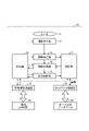
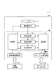
- FIG. 1 is a block diagram showing a schematic configuration example of the image pickup apparatus 10 according to the first embodiment.
- the image pickup apparatus 10 includes an optical system 11, an image sensor unit 12, an image processing unit 13, an image comparison unit 14, a situation analysis unit 15, a control unit 16, and a storage unit 17.
- a vehicle information connection unit 18 and a network connection unit 19 are provided.
- the image pickup device 10 is connected to the vehicle 20 via the vehicle information connection unit 18, and is also connected to the database 30 on the server via the network connection unit 19.
- the optical system 11 has one or a plurality of lenses.
- the optical system 11 guides the light (incident light) from the subject to the image sensor unit 12 and forms an image on the light receiving surface of the image sensor unit 12.
- the image pickup element unit 12 has a plurality of pixels each having a light receiving element. These pixels are arranged in a two-dimensional lattice pattern (matrix pattern), for example.
- the image sensor unit 12 takes an image according to the exposure control by the control unit 16 and transmits the exposure data to the image processing unit 13.
- CMOS Complementary Metal Oxide Semiconductor
- CCD Charge Coupled Device
- the image processing unit 13 receives exposure data from the image sensor unit 12.
- the image processing unit 13 performs image processing based on the exposure data according to the processing instruction from the control unit 16. For example, the image processing unit 13 generates various images such as a bird's-eye view image from the exposure data.
- the image processing unit 13 transmits various images (image data) such as a bird's-eye view image to the storage unit 17.
- the image comparison unit 14 performs image comparison using the image data generated by the image processing unit 13 and the image data read from the storage unit 17 in accordance with the comparison instruction from the control unit 16.
- the image comparison unit 14 transmits the comparison result based on each image data to the control unit 16, the situation analysis unit 15, and the like.
- the situation analysis unit 15 performs a situation analysis based on the comparison result transmitted from the image comparison unit 14 according to the analysis instruction from the control unit 16. For example, the situation analysis unit 15 analyzes the situation (state) of the vehicle 20 according to the amount of deviation from the design position (predetermined installation position) of the image pickup device 10. The situation analysis unit 15 transmits the analysis result for the situation of the vehicle 20 to the control unit 16, the storage unit 17, and the like.
- the control unit 16 issues instructions to each unit such as the image sensor unit 12, the image processing unit 13, the image comparison unit 14, the situation analysis unit 15, and the storage unit 17, and controls each unit. Further, the control unit 16 transmits data such as analysis result notification and automatic driving level instruction to the vehicle 20 via the vehicle information connection unit 18.
- the control unit 16 receives travel data (an example of vehicle information) from the vehicle 20 via the vehicle information connection unit 18.
- the control unit 16 transmits a server access instruction to the storage unit 17.
- a processor such as a CPU (Central Processing Unit) is used.
- the CPU includes a ROM (Read Only Memory), a RAM, and the like, and controls the operation of each part by using the RAM as a work memory according to a program stored in the ROM in advance.
- the storage unit 17 stores various data such as image data.
- a non-volatile memory such as a flash memory or a hard disk drive is used.
- the storage unit 17 sends and receives various data to and from the server, that is, the database 30 on the server, via the network connection unit 19 in response to the server access instruction from the control unit 16.
- the vehicle information connection unit 18 enables transmission / reception of various data (for example, vehicle information, analysis result notification, automatic driving level instruction, etc.) to the vehicle 20 by a communication standard such as CAN (Controller Area Network).
- a communication standard such as CAN (Controller Area Network).
- CAN Controller Area Network
- various communication I / Fs (interfaces) corresponding to CAN and the like are used.
- the network connection unit 19 enables transmission / reception of various data (for example, image data, etc.) to the database 30 on the server according to various communication standards.
- various communication I / Fs corresponding to a wireless WAN (Wide Area Network) or the like are used.
- the vehicle 20 is connected to the image pickup device 10 via the vehicle information connection unit 18.
- the vehicle 20 transmits and receives various data to and from the control unit 16 via the vehicle information connection unit 18.
- the vehicle 20 transmits various data such as vehicle information (for example, driving data) to the control unit 16, and also receives various data such as analysis result notification and automatic driving level instruction from the control unit 16.
- the database 30 is connected to the image pickup apparatus 10 via the network connection unit 19.
- the database 30 is, for example, a database on a server connected to a communication network such as a network, and stores and manages various data.
- the database 30 receives and stores various data such as image data from the storage unit 17.
- Each of the above-mentioned image processing unit 13, image comparison unit 14, situation analysis unit 15, control unit 16, and the like may be configured by either hardware or software, and these configurations are particularly particular. Not limited.
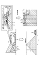
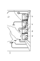
- FIG. 2 is an explanatory diagram for explaining a bird's-eye view image generation process according to the first embodiment.
- the image pickup apparatus 10 is provided, for example, on the upper part of the windshield in the vehicle interior of the vehicle 20 or on the front portion of the vehicle 20.
- the image pickup device 10 is directed to the front of the vehicle 20 which is the own vehicle, and is mainly used for detecting a preceding vehicle, a pedestrian, a road, a lane, a road surface sign, an obstacle, a traffic light, a traffic sign, or the like.
- the image pickup device 10 is, for example, a wide-angle camera.
- the front of the vehicle 20 is imaged by the image pickup device 10, and the image G is obtained.
- the obtained image G includes an object (subject) such as another vehicle or an obstacle, and avoids the area of the object and avoids the free space R on the road (diagonal hatched area in the image G of FIG. 2).
- the free space R is an area where there are no other vehicles, obstacles, or other objects, and which is a travelable area / travel target area. This free space R may be a flat area on the road or a space area on the road.
- Virtual conversion is performed on the above-mentioned image G, and a bird's-eye view image Ga based on the virtual viewpoint is generated.
- the free space Ra hatchched area in the bird's-eye view image Ga in FIG. 2
- the image processing unit 13 For example, the area on the road in front of the vehicle 20 is detected as free space Ra by image processing while avoiding objects such as other vehicles and obstacles.
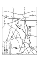
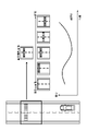
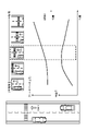
- FIG. 3 is an explanatory diagram showing measurement points according to the first embodiment.
- the measurement point is an image acquisition point for acquiring an image.
- measurement points are set on the map.
- the measurement points include a point for acquiring an image with the vehicle 20 (without data), a point for acquiring an image with the vehicle 20 (with data), and a point for acquiring an image with a fixed point camera.
- the point at which the vehicle 20 acquires an image (no data) is a measurement point at which the vehicle 20 acquires an image in the absence of data (pre-photographed image) corresponding to this measurement point.
- the point at which the vehicle 20 acquires an image (with data) is a measurement point at which the vehicle 20 acquires an image in a state where there is data (pre-photographed image) corresponding to this measurement point.
- the point at which an image is acquired by a fixed-point camera is a measurement point at which a fixed-point camera acquires an image.
- Such measurement points are preset along the road on the map.
- the setting point information indicating the measurement point is stored in, for example, a database 30 or the like, and is appropriately read and used by the vehicle 20 or the image pickup device 10.
- the measurement point information may be read by either the vehicle 20 or the image pickup apparatus 10, and may be transmitted from one of the read information to the other that has not read the information.
- the route is automatically set by the vehicle 20 (routing).
- the route is set in the order of shortest running time and running distance. In the example of FIG. 3, three routes are set. After that, one route is selected by the driver or the like, and automatic driving is started at the automatic driving level according to the route. Then, the vehicle 20 travels along the route. The details of the automatic operation level will be described later.
- the image pickup device 10 appropriately captures an image at the measurement point based on the measurement point information.
- the image pickup device 10 can acquire vehicle information (for example, position information of the vehicle 20) from the vehicle 20 and recognize the position of the vehicle 20.
- vehicle information for example, position information of the vehicle 20
- the image pickup apparatus 10 performs imaging in real time, and when the vehicle 20 reaches the measurement point, the image pickup device 10 captures and acquires an image of the own vehicle at the measurement point.
- the image pickup apparatus 10 reads in advance the pre-photographed image for the measurement point from the database 30 at the timing when the vehicle 20 approaches the measurement point (position at a predetermined distance to the measurement point).
- the image pickup apparatus 10 compares the pre-photographed image read in advance with the own vehicle image acquired at the measurement point.
- the pre-photographed image is converted into a bird's-eye view image and stored in the database 30, the own vehicle image is also converted into a bird's-eye view image by the above-mentioned bird's-eye view image generation process, and the above-mentioned comparison is performed.
- the own vehicle image (first image) is an image obtained by the image pickup device 10 provided in the vehicle 20 currently traveling on the route.
- the pre-photographed image (second image) is stored in the database 30, and the pre-acquired image (for example, the pre-photographed image by the image pickup device 10 or the fixed point camera) from which the own vehicle image is obtained).
- the vehicle information includes various information regarding the vehicle 20, and includes, for example, information regarding the movement of the vehicle 20 such as the position, speed, acceleration, angular velocity, and traveling direction of the vehicle 20.
- the position of the vehicle 20 is measured by, for example, a positioning system that combines a satellite navigation system such as GNSS (Global Navigation Satellite System) that measures the current position using an artificial satellite, an altitude meter, an acceleration sensor, a gyroscope, and the like.
- GNSS Global Navigation Satellite System
- the own vehicle image acquired at the measurement point is stored in the storage unit 17 in association with the measurement point.
- This own vehicle image (image data) is transmitted from the image pickup apparatus 10 to the database 30.
- the database 30 receives the own vehicle image transmitted from the image pickup apparatus 10 and stores and manages it as a pre-photographed image.
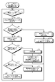
- FIG. 4 is a flowchart showing the flow of the automatic operation process according to the first embodiment.
- step S1 determines whether or not the vehicle 20 is within a predetermined distance Xm to the measurement point (step S1), and waits until the vehicle 20 reaches the measurement point at a predetermined distance Xm (NO in step S1).
- the control unit 16 recognizes the position of the vehicle 20 from the vehicle information obtained from the vehicle 20.
- the control unit 16 determines that the vehicle 20 is within a predetermined distance Xm to the measurement point (YES in step S1), the control unit 16 shifts the current automatic driving level to the measurement automatic driving level (step S2). That is, automatic operation (implementation) of the automatic operation level for measurement is permitted.
- the measurement automatic driving level is an automatic driving level that controls the vehicle 20 based on automatic driving information such as the speed and position of the vehicle 20 suitable for measurement. As a result, the image pickup apparatus 10 can take an image under conditions suitable for measurement, so that an accurate image of the own vehicle can be obtained.
- the control unit 16 determines whether or not there is data of a comparable image (pre-photographed image) at the measurement point (step S3).
- the control unit 16 determines that the measurement point has comparable image data (YES in step S3)
- the image processing unit 13 and the image comparison unit 14 capture, compare, and store the images. (Step S4). The process of step S4 will be described in detail later.
- the control unit 16 determines whether or not the image comparison difference (difference amount) is equal to or less than a predetermined threshold value A (step S5).
- the control unit 16 determines whether or not the measurement point is a fixed point camera point (a point at which an image is acquired by the fixed point camera). (Step S6).
- control unit 16 determines that the measurement point is a fixed point camera point (YES in step S6)
- the control unit 16 shifts the current automatic driving level to the original automatic driving level according to the route (step S7). That is, automatic driving at the original automatic driving level is permitted.
- the control unit 16 determines that the measurement point is not a fixed point camera point (NO in step S6)
- the control unit 16 transmits the saved image data to the server (step S8).
- the server stores the saved image data in the database 30.
- step S5 when the control unit 16 determines that the image comparison difference is not equal to or less than the predetermined threshold value A (NO in step S5), the situation analysis unit 15 performs a situation analysis regarding the situation of the own vehicle (step S9). .. The control unit 16 lowers the current automatic driving level and notifies the driver according to the flag set in the situation analysis (step S10). That is, automatic driving at the current automatic driving level is prohibited.
- step S9 will be described in detail later.
- step S3 when the control unit 16 determines that there is no comparable image data at the measurement point (NO in step S3), the image processing unit 13 and the image comparison unit 14 capture the image. , Select and save (step S11). The control unit 16 shifts the current automatic driving level to the original automatic driving level according to the route (step S12). That is, automatic driving at the original automatic driving level is permitted.
- step S11 will be described in detail later.
- step S3 even if the image (pre-photographed image) corresponding to the measurement point is in the database 30, the image is not always a comparable image. For example, it is difficult to obtain an accurate comparison result even if the daytime image (pre-photographed image) of the measurement point is compared with the image (own vehicle image) acquired during night driving. Therefore, when the image pickup device 10 saves the image in the database 30 on the server, the image pickup apparatus 10 associates the incidental information about the image with the image and saves the image together with the image. Examples of the incidental information include exposure information of the image (environmental illuminance, gain value, histogram, etc.), shooting date and time of the image, vehicle type from which the image was acquired, and the like.
- the incidental information include exposure information of the image (environmental illuminance, gain value, histogram, etc.), shooting date and time of the image, vehicle type from which the image was acquired, and the like.
- the control unit 16 determines whether or not there is a comparable image based on the incidental information associated with the image (pre-photographed image). For example, in step S3, when the difference between the environmental illuminance related to the image to be compared and the environmental illuminance acquired by the own vehicle camera (imaging device 10) closest to the image acquisition is equal to or less than a certain predetermined value, the control unit 16 may use the control unit 16. Judge that there is comparable image data. Further, the control unit 16 may use the same shooting time zone for the image to be compared and the shooting time zone of the own vehicle camera (before / after sunrise, daytime, around sunset, nighttime), or when the own vehicle camera has the same shooting time zone.
- the control unit 16 has image data that can be compared when the image data to be compared is data within a certain period of time and after the date when the condition change near the measurement point occurs.
- the date on which the condition change near the above-mentioned measurement point occurs is, for example, the date and time when construction or road sign change can be grasped, and the date and time which is found later by detecting the difference by the automatic driving process.
- the score is not limited to this, and may be scored by each condition weighting based on the various information.
- the control unit 16 may select and use the image data most suitable for comparison according to the score, or may use a plurality of image data having a certain score or more as the comparison target. good.
- FIG. 5 is a flowchart showing the flow of the image comparison process according to the first embodiment.
- the image comparison process is the process of step S4 during the automatic operation process shown in FIG.
- FIG. 6 is an explanatory diagram for explaining the image comparison process according to the first embodiment.
- the number of frames is M (frames No. 1 to M).
- the image comparison unit 14 has a frame No.
- the difference amount DN is an example of the difference information.
- a pre-photographed image of a measurement point is read out.
- the difference amount DN between these own vehicle images and the pre-photographed image is obtained, and the image with the minimum difference amount DN (the own vehicle image in the center of the own vehicle image in FIG. 6) is retained as transmission data. Will be done.
- the image having the minimum difference amount DN can be used for image comparison as the own vehicle image.
- the control unit 16 may issue an instruction to the vehicle 20 to reduce the speed of the vehicle 20 or increase the inter-vehicle distance of the vehicle 20. After that, the control unit 16 may shift the image comparison process to the abnormality determination process, for example.
- the threshold value B shown in FIG. 6 is merely an example, and an image in which the difference amount DN is the minimum and is equal to or less than the threshold value B is retained as transmission data.
- an image in which the difference amount DN is equal to or higher than a predetermined threshold value may be stored as transmission data.
- the number of images in which the difference amount DN is equal to or greater than a predetermined threshold value may be one or more, and may be one or a plurality.
- FIG. 7 is a flowchart showing the flow of the situation analysis process according to the first embodiment.
- the situation analysis process is the process of step S9 during the automatic operation process shown in FIG. 8 to 12 are explanatory views for explaining the situation analysis process according to the first embodiment.
- the situation analysis unit 15 determines whether or not the difference amount DMIN between the image (own vehicle image) and the pre-photographed image is equal to or less than a predetermined threshold value C (threshold value C ⁇ threshold value A ⁇ threshold value B). Is determined (step S31).
- the image of DMIN is sent to the server together with the flag information (step S33).
- the DMIN image (image data) is stored in the database 30 together with the flag information.
- the image acquisition failure flag is a flag indicating that the image acquisition is not performed well and the difference comparison is not performed correctly.
- the situation analysis unit 15 determines that the difference amount D MIN is equal to or less than the predetermined threshold value C (YES in step S31)
- the frame No. The motion vector is obtained from each other's feature points of the N DMIN image (own vehicle image) and the pre-photographed image of the measurement point, and the state of the camera (imaging device 10) is detected from the motion vector (step S34).
- the situation analysis unit 15 analyzes and detects the situation of the image pickup apparatus 10, that is, the situation of the vehicle 20 from the motion vector.
- the motion vector is an example of the difference information, and is the difference between the feature points of the own vehicle image and the feature points of the pre-taken image.
- the movement amount and movement direction of these feature points are obtained as motion vectors.
- feature points are used as the features of the image, the feature points are not limited to these, and feature lines may be used, for example. These feature points, feature lines, and the like can be obtained from lanes such as white lines and yellow lines, for example.
- the situation analysis unit 15 determines whether or not the camera (imaging device 10) is largely displaced in the vertical direction from the design position (predetermined installation position), or is largely displaced in the pitch or roll direction. Is determined (step S35).
- the vehicle subduction NG flag 1 is set. (Step S36), the process proceeds to step S37.
- the vehicle subduction NG flag is a flag indicating that puncture, overload, or the like may have occurred.
- the situation analysis unit 15 determines whether or not the camera is significantly displaced in the left-right direction from the design position (NO). Step S37).
- the traveling position NG flag 1 (step S38), and the process proceeds to step S39.
- the traveling position NG flag (traveling position abnormality flag) is a flag indicating that the traveling position of the automatic driving may be deviated for some reason.
- step S35 and step S37 whether or not the camera is significantly displaced is determined by whether or not the movement amount (displacement amount) based on the motion vector is equal to or greater than a predetermined threshold value. That is, when the movement amount is equal to or more than a predetermined threshold value, it is determined that the camera is largely displaced, and when the movement amount is smaller than the predetermined threshold value, it is determined that the camera is not significantly displaced.
- the direction of movement is also known, so it is possible to determine in which direction the vehicle is displaced.
- the situation analysis unit 15 determines whether or not there is a certain area or more in which the motion vector cannot be detected (step). S39).
- the recognition failure subject existence flag 1 (step S40)
- the process proceeds to step S33.
- the recognition failure subject existence flag is a flag indicating that the free space detection is not performed well or the road surface sign is not recognized well.
- the DMIN image is sent to the server along with the flag information.
- the DMIN image (image data) is stored in the database 30 together with the flag information.
- a service may be provided in which the flag and the image are confirmed by human eyes or software, and the driver is urged to inspect according to the contents.
- the own vehicle image G1 is acquired and the pre-photographed image G2 is read.
- the own vehicle image G1 is a bird's-eye view image, and has a free space R1 in which an object such as another vehicle or an obstacle does not exist.
- the pre-photographed image G2 is also a bird's-eye view image, and has a free space R2 in which an object such as another vehicle or an obstacle does not exist.
- This pre-photographed image G2 is, for example, an image captured on another day by another vehicle, a fixed point camera, or the like.
- step S34 described above the feature points (common features) of the own vehicle image G1 and the pre-photographed image G2 are obtained, and the motion vector is obtained from those feature points. Specifically, in the own vehicle image G1 and the pre-photographed image G2, only the AND (logical product) region of the free spaces R1 and R2, that is, the common region is subtracted. First, in the own vehicle image G1 and the pre-photographed image G2, a common free space (common area) R3 in which an object such as another vehicle or an obstacle does not exist is required.
- the feature points in the free space R3 of the own vehicle image G1 are obtained, the feature points in the free space R3 of the pre-photographed image G2 are obtained, and the motion vectors (movement amount and movement direction) of those feature points are calculated. Will be done.
- the object is overlooked by the free space detection. For example, there is a possibility that an undetectable object (subject) such as a traffic cone is placed.
- the own vehicle image G1c has something that does not exist in the pre-photographed image G2 (road surface sign in FIG. 11).
- the road sign is recognized in the free space detection, and the area of the road sign is excluded from the difference processing.
- the image comparison unit 14 recognizes the road surface sign included in the free space R1 by image processing, and executes the difference processing except for the area of the road surface sign. Road signs do not pose a problem for the vehicle 20 to travel.
- the object is not recognized as a road sign by the free space detection. For example, there is a possibility that an object (subject) other than the road sign is placed.
- the automatic operation level control process (change process) according to the first embodiment will be described.
- the automatic driving level is controlled according to the above-mentioned flags (image acquisition failure flag, vehicle subduction NG flag, traveling position NG flag, recognition failure subject existence flag).
- flags image acquisition failure flag, vehicle subduction NG flag, traveling position NG flag, recognition failure subject existence flag.
- the vehicle subduction NG flag 1
- the vehicle 20 automatically travels by widening the distance between the front and rear vehicles.
- the control unit 16 notifies the driver that the vehicle has sunk, and switches the automatic driving level to the hands-on automatic driving level. For example, the control unit 16 changes the automatic operation level from level 3 to level 2 or lower.
- the vehicle 20 automatically travels by widening the distance between the vehicle and another vehicle in the lateral direction or the wall.
- the control unit 16 notifies the driver that the lateral vehicle spacing cannot be secured, and switches the automatic driving level to the hands-on automatic driving level. For example, the control unit 16 changes the automatic operation level from level 3 to level 2 or lower.
- the control unit 16 sets the speed to slow down when another vehicle passes the measurement point where this flag is generated, and switches the automatic driving level to the hands-on automatic driving level. For example, the control unit 16 changes the automatic operation level from level 3 to level 2 or lower.
- control unit 16 removes the measurement point area from the routing or makes it a hands-on automatic driving area even if it is included in the route until countermeasures are taken. ..
- the control unit 16 informs the driver that there is an abnormality. Notify and switch the automatic driving level to the hands-on automatic driving level. For example, the control unit 16 changes the automatic operation level from level 3 to level 2 or lower.
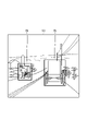
- the control unit 16 reports to the driver that the unrecognizable object Rb is in the image G3, and the control unit 16 reports to the driver.
- the object Rb is a carriage, and in the example of FIG. 14, the object Rb is a deer.
- ODD is a driving environment condition (various conditions) that is a prerequisite for the operation of the automatic driving system by design, and the automatic driving system operates normally when the driving environment condition is satisfied. On the contrary, if some conditions are lacking, there is a risk that automatic operation will be hindered, so it is necessary to take measures to stop operation or switch to manual operation.
- the automated driving level is defined by, for example, SAE (Society of Automotive Engineers) in 6 stages from 0 to 5. Specifically, the automated driving levels are no driving automation (level 0), driving support (level 1), partial driving automation (level 2), conditional driving automation (level 3), and advanced driving automation (level 4). And fully automated driving (level 5).
- SAE Society of Automotive Engineers
- the subject is the driver, and the driving area (driving place) is not limited.
- the driver performs all dynamic driving tasks.
- Level 1 driving support
- the subject is the driver, and the driving area is limited.
- the driving automation system continuously performs either vertical or horizontal (not both simultaneous) vehicle motion control subtasks of the dynamic driving task in a specific limited area.
- the driver is expected to perform the remaining dynamic driving tasks.
- the car supports one of the accelerator, brake, and steering wheel operations (turning right / left, keeping lane).
- Specific examples of Level 1 automatic driving functions include ACC (adaptive cruise control) that keeps the distance between vehicles constant, collision damage mitigation brakes, lane keep assist, garage entry, and parking assist.
- the subject is the driver, and the driving area is limited.
- the driving automation system continuously performs the vertical and lateral vehicle motion control subtasks of the dynamic driving task in a specific limited area.
- the driver is expected to complete the detection and response of the object / event, which is a subtask of the dynamic driving task, and monitor the system.
- the vehicle simultaneously supports a plurality of operations such as accelerator, brake, and steering wheel operations.
- the main body is a car, and the driving area is limited.
- the driving automation system continuously performs all dynamic driving tasks in a limited area.
- the user who is ready to respond to the case where it is difficult to continue the operation requests not only the system failure related to the dynamic driving task execution system in the system of another vehicle but also the intervention issued by the automatic driving system. Is expected to be accepted and respond appropriately.
- the system performs all driving operations (eg, acceleration, steering, braking) only in certain environments and conditions (eg, on highways, in weather except extreme environments, etc.).
- the driver operates the vehicle.
- the main body is a car, and the driving area is limited.
- the driving automation system continuously performs all dynamic driving tasks and responses to difficult task continuations in a limited area. Users are not expected to respond to requests for intervention if it is difficult to continue operation. For example, at level 4, the system performs all driving operations (eg, acceleration, steering, braking) only in certain environments and conditions (eg, on highways, in weather except extreme environments, etc.). As long as the conditions continue, the driver will not respond to emergencies and will not be involved in the driving operation at all.
- driving operations eg, acceleration, steering, braking
- the main body is the car, and the driving area is not limited.
- the driving automation system continuously and unrestrictedly (not within a limited area) performs all dynamic driving tasks and responses to cases where continuation of work is difficult. Users are not expected to respond to requests for intervention if it is difficult to continue operation. For example, at level 5, a driver is not required, the traveling area is not limited, and it is possible to drive automatically on any road.
- the automatic operation level is defined in 6 stages from 0 to 5, but the present invention is not limited to this, and for example, it may be defined in 7 stages or more or 5 stages or less. Further, the content of each automatic operation level can be changed to a content different from the above-mentioned content, and can be appropriately defined.
- FIG. 15 is a flowchart showing the flow of the image selection process according to the first embodiment.
- the image selection process is the process of step S11 during the automatic operation process shown in FIG.
- FIG. 16 is an explanatory diagram for explaining the image selection process according to the first embodiment.
- VMAX 0 (step S52).
- the number of frames is M (frames No. 1 to M).
- the image comparison unit 14 determines that the free space area SN is not equal to or greater than the predetermined threshold value D (NO in step S53), or determines that the feature amount VN in the free space is not larger than VMAX (NO). NO in step S54), the process proceeds to step S56 as it is.
- the free space area SN and the feature amount VN in the free space are examples of free space information regarding the free space.
- the free space area SN of these own vehicle images is obtained, and the feature amount VN in the free space is obtained.
- An image in which the free space area SN is equal to or larger than a predetermined threshold value D and the feature amount VN is maximum (the own vehicle image in the center of the own vehicle image in FIG. 16) is held as transmission data.
- an image in which the free space area SN is equal to or larger than a predetermined threshold value D and the feature amount VN is maximum can be used for image comparison as a pre-photographed image.
- the free space area SN is smaller than the predetermined threshold value D, the own vehicle image having the free space area SN is rejected as transmission data.
- the free space area SN is equal to or greater than the predetermined threshold value D and the feature amount VN is maximum, for example, the free space area SN is equal to or greater than the predetermined threshold value D.
- An image in which the feature amount VN is equal to or larger than a predetermined threshold value may be stored as transmission data.
- the number of images in which the feature amount VN is equal to or greater than a predetermined threshold value may be one or more, and may be one or a plurality.
- the first free space R1 on the road on which the own vehicle travels and is included in the own vehicle image (first image) is obtained in advance.
- the difference information from the second free space R2 on the road included in the pre-photographed image (second image) is acquired, and the automatic driving level of the own vehicle is controlled based on the difference information.
- difference information is obtained based on the free spaces R1 and R2 in which no object such as another vehicle or obstacle exists, and the automatic driving level is controlled based on the difference information. It is possible to suppress the occurrence of false recognition, and it is possible to appropriately control the automatic operation.
- the actually captured image as the pre-photographed image, it is possible to cope with daily changes (for example, installation of road sign, collapse of road, etc.).
- daily changes for example, installation of road sign, collapse of road, etc.
- difference information is obtained in response to daily changes, and the automatic operation level is controlled based on the difference information, so it is possible to suppress the occurrence of false recognition due to daily changes.
- Control related to automatic operation can be appropriately performed. If the image generated by the simulation is used as a pre-photographed image to be compared, it is difficult to respond to daily changes, and misrecognition due to the daily changes may occur.
- the free spaces R1 and R2 are detected by recognizing an object (subject) in the image by the image processing unit 13 and detecting a predetermined area while avoiding the object.
- the area in front of the vehicle may be detected as the free space R.
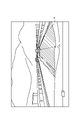
- FIG. 17 is an explanatory diagram for explaining another example of free space detection according to the first embodiment.
- the free space R with respect to the vehicle in front of the own vehicle is set to 80 m.
- In automatic driving usually, in order to secure the inter-vehicle distance according to the speed of the vehicle 20, there is a certain inter-vehicle distance with respect to the vehicle in front of the own vehicle.
- FIG. 18 is a block diagram showing a schematic configuration example of the imaging system 1 according to the second embodiment.
- the differences from the first embodiment will be mainly described, and other explanations will be omitted.
- the image pickup system 1 includes an image pickup device 10A and a processing device 10B.
- the image pickup device 10A includes an optical system 11 and an image pickup element unit 12.
- the processing device 10B includes an image processing unit 13, an image comparison unit 14, a situation analysis unit 15, a control unit 16, a storage unit 17, a vehicle information connection unit 18, and a network connection unit 19.
- the image pickup apparatus 10A and the processing apparatus 10B are formed so as to be able to communicate with each other by wire or wirelessly.
- another control unit may be provided in the above-mentioned image pickup apparatus 10A.
- the second embodiment it is possible to realize miniaturization of the image pickup apparatus 10A by separating the image pickup apparatus 10A and the processing apparatus 10B. As a result, the degree of freedom in installing the image pickup apparatus 10A can be increased, and the convenience of the user can be improved. According to the second embodiment, the same effect as that of the first embodiment can be obtained.
- FIG. 19 is a block diagram showing a schematic configuration example of the imaging system 1A according to the third embodiment.
- the differences from the first embodiment will be mainly described, and other explanations will be omitted.
- the image pickup system 1A includes an image pickup device 10C and a processing device 10D.
- the image pickup device 10C includes an optical system 11, an image pickup element section 12, and an image processing section 13.
- the processing device 10D includes an image comparison unit 14, a situation analysis unit 15, a control unit 16, a storage unit 17, a vehicle information connection unit 18, and a network connection unit 19.
- the image pickup apparatus 10C and the processing apparatus 10D are formed so as to be able to communicate with each other by wire or wirelessly.
- another control unit may be provided in the above-mentioned image pickup apparatus 10C.
- the third embodiment it is possible to realize miniaturization of the image pickup device 10C by separating the image pickup device 10C and the processing device 10D. As a result, the degree of freedom in installing the image pickup apparatus 10C can be increased, and the convenience of the user can be improved. According to the third embodiment, the same effect as that of the first embodiment can be obtained.
- the image processing unit 13 is provided in the image pickup apparatus 10C, but the present invention is not limited to this.
- the image pickup apparatus 10C may be provided with one or more of the image comparison unit 14, the situation analysis unit 15, the control unit 16, and the storage unit 17. That is, the image processing unit 13, the image comparison unit 14, the situation analysis unit 15, the control unit 16, and the storage unit 17 can be appropriately distributed and provided to the image pickup device 10C and the processing device 10D.
- the own vehicle image and the pre-photographed image are compared in one frame according to the measurement point, but the present invention is not limited to this.
- the image of the own vehicle and the image taken in advance may be compared in a plurality of continuous frames including before and after the measurement point.
- each pre-photographed image corresponding to before and after the measurement point is also stored in advance.
- the automatic operation level is controlled based on the difference information, but the present invention is not limited to this.
- one or both of the speed of the own vehicle and the inter-vehicle distance may be controlled by the control unit 16 based on the difference information.
- the control unit 16 in addition to controlling the automatic driving level, it is possible to control one or both of the speed and the inter-vehicle distance of the own vehicle.
- the image pickup apparatus 10 performs free space detection (for example, free space detection includes recognition of obstacles and road signs), but the present invention is not limited to this. ..
- another camera may perform free space detection.
- the detection result (recognition result) detected by another camera is transmitted to the image pickup apparatus 10 together with the camera position information.
- a detection device other than a camera such as LiDAR (Light Detection and Ranging, Laser Imaging Detection and Ranging) or radar.
- the vehicle 20 receives the pre-photographed image to be compared at the timing (position at a predetermined distance from the measurement point) when the vehicle 20 approaches the measurement point (corresponding point). It is not limited to.
- the pre-photographed image may be received in advance by downloading at the time of routing (route setting) before traveling. By receiving the pre-photographed image in advance, the comparison process can be performed even in a place where radio waves do not reach and cannot be received, such as a tunnel.
- a route with a pre-photographed image may be preferentially selected for routing.
- the pre-photographed image may be an image taken by another vehicle.
- the pre-photographed image may be received from the server, or may be received from a road device that stores the pre-photographed image. If the route is a well-traveled road, the deterioration of the road can be accurately detected by saving the image of the own vehicle as a pre-captured image and using it as a comparison target.
- the lanes (white lines, etc.) in the image may be different by comparing the images as they are, or if the lanes are unnecessary, the lanes may be recognized and masked, and the lanes may be excluded from the comparison target.
- the difference in the comparison result is an unrecognizable three-dimensional object or road surface sign
- the image may be transmitted to the server and used as teacher data for learning so that the image can be recognized in the machine learning system.
- the above-mentioned image pickup device 10 can be applied not only to a camera facing forward but also to a camera facing sideways or backward. Further, the image pickup device 10 can be applied to electronic devices such as drive recorders and mobile terminals other than cameras. This electronic device is attached to the vehicle 20.
- the present technology can also have the following configurations.
- the image processing unit further comprises an image processing unit that detects the first free space from the first image and detects the second free space from the second image.
- (3) The first free space and the second free space are Have common areas with each other
- the difference information is The amount of difference between the common area of the first free space and the common area of the second free space is included.
- a situation analysis unit that analyzes the situation of the vehicle based on the difference information is further provided.
- the control unit Controlling the automatic driving level of the vehicle according to the situation of the vehicle,
- the signal processing device according to any one of (1) to (3) above.
- the first free space and the second free space are Have common characteristics with each other
- the difference information is The movement amount and the movement direction between the common feature of the first free space and the common feature of the second free space are included.
- the signal processing device according to (4) above.
- the situation analysis unit As the situation of the vehicle, the acquisition failure of the first image, the subduction of the vehicle, the traveling position abnormality of the vehicle, or the recognition failure of the first image is analyzed.
- the control unit When the situation analysis unit recognizes the acquisition failure of the first image, the subduction of the vehicle, the traveling position abnormality of the vehicle, or the recognition failure of the first image, the automatic driving level of the vehicle is lowered.
- the signal processing apparatus according to (4) or (5) above.
- the control unit When the vehicle is at a predetermined distance from the image acquisition point for acquiring the first image, the automatic driving level of the vehicle is shifted to the measurement automatic driving level for acquiring the first image.
- the signal processing device according to any one of (1) to (6) above.
- the control unit When there is no second image corresponding to the image acquisition point for acquiring the first image, the measurement automatic driving level of the vehicle is shifted to the original automatic driving level of the vehicle.
- the signal processing device according to (7) above.
- the image comparison unit is The first image is repeatedly captured from a time when the vehicle is at a predetermined distance from the image acquisition point at which the first image is acquired, and one or more of the first images captured. Select and use 1 image, The signal processing device according to any one of (1) to (8) above.
- the image comparison unit is Obtaining individual difference information between the plurality of captured first images and the second image, One or more of the first images are selected from the plurality of captured first images based on the acquired individual difference information.
- the signal processing device according to (9) above.
- the individual difference information is These are the differences between the first free space and the second free space, respectively.
- the image comparison unit is Select one or more of the first images whose difference amount is equal to or greater than a predetermined threshold value.
- the image comparison unit is One or more of the first images used are stored as the second image.
- the image comparison unit is The first image is repeatedly captured from a time when the vehicle is at a predetermined distance from the image acquisition point at which the first image is acquired, and one or more of the first images captured. Select 1 image and save it, The signal processing device according to any one of (1) to (12) above.
- the image comparison unit is Acquire free space information regarding the first free space for each captured first image, and obtain One or more of the first images are selected from the plurality of captured first images based on the acquired free space information for each of the first images.
- the free space information for each of the first images is Each is the area of the first free space.
- the image comparison unit is Select one or more of the first images whose area is greater than or equal to a predetermined threshold.
- the free space information for each of the first images is Each is a feature amount of the first free space.
- the image comparison unit is Select one or more of the first images whose feature amount is equal to or greater than a predetermined threshold value.
- the image comparison unit is The difference information is acquired except for the area of the road sign included in the first free space.
- the signal processing device according to any one of (1) to (16) above.
- the first image and the second image are A bird's-eye view image obtained from a predetermined virtual viewpoint,
- the control unit Controlling either or both of the vehicle speed and the inter-vehicle distance,
- (20) Acquisition of difference information between the first free space on the road in the first image and the second free space on the road in the second image obtained in advance, which is the road on which the vehicle travels. death, Controlling the automatic driving level of the vehicle based on the difference information, Signal processing method.
- the signal processing device according to any one of (1) to (19) above is used. Signal processing method.
- Image pickup system 1A Image pickup system 10
- Image pickup device 11 Optical system 12
- Image pickup element section 13 Image processing section 14
- Image comparison section 15 Situation analysis section 16
- Control section 17 Storage section 18
- Vehicle information connection section 19 Network connection section 20
- Vehicle 30 Database G Image Ga Bird's-eye view image G1 own vehicle image G1a to G1d own vehicle image G2 pre-shooting image G3 image R free space Ra free space R1 to R3 free space
Landscapes
- Engineering & Computer Science (AREA)
- Automation & Control Theory (AREA)
- Physics & Mathematics (AREA)
- General Physics & Mathematics (AREA)
- Multimedia (AREA)
- Theoretical Computer Science (AREA)
- Human Computer Interaction (AREA)
- Transportation (AREA)
- Mechanical Engineering (AREA)
- Computer Vision & Pattern Recognition (AREA)
- Traffic Control Systems (AREA)
Abstract
本開示に係る一形態の信号処理装置(例えば、撮像装置10)は、車両が走行する道路であって第1の画像中の前記道路上の第1のフリースペースと、あらかじめ求められた第2の画像中の前記道路上の第2のフリースペースとの差分情報を取得する画像比較部(14)と、前記差分情報に基づき、前記車両の自動運転レベルを制御する制御部(16)と、を備える。
Description
本開示は、信号処理装置及び信号処理方法に関する。
近年、自動運転技術の開発が加速している。例えば、地図データに基づいてシミュレーションにより生成された区画線を含む画像と、現在位置の区画線を含む画像とを比較し、車線に対する自車の位置や方向の誤認識を抑制できる車線認識システムが開発されている(例えば、特許文献1参照)。
しかしながら、前述の車線認識システムでは、他車両や障害物等の物体が道路上に存在する場合、画像内の物体と車線を区別することが考慮されておらず、車線に対する自車の位置や方向の誤認識が生じることがある。この誤認識が生じると、自動運転に係る制御を適切に行うことは難しい。
そこで、本開示では、自動運転に係る制御を適切に行うことが可能な信号処理装置及び信号処理方法を提供する。
本開示に係る一形態の信号処理装置は、車両が走行する道路であって第1の画像中の前記道路上の第1のフリースペースと、あらかじめ求められた第2の画像中の前記道路上の第2のフリースペースとの差分情報を取得する画像比較部と、前記差分情報に基づき、前記車両の自動運転レベルを制御する制御部と、を備える。
以下に、本開示の実施形態について図面に基づいて詳細に説明する。なお、以下の実施形態において、同一の部位には同一の符号を付することにより重複する説明を省略する。
また、以下に示す項目順序に従って本開示を説明する。
1.第1の実施形態
1-1.撮像装置の概略構成例
1-2.俯瞰画像の生成処理
1-3.測定ポイント(画像取得ポイント)
1-4.自動運転処理
1-5.画像比較処理
1-6.状況解析処理
1-7.自動運転レベルの制御処理
1-8.画像選択処理
1-9.作用・効果
2.第2の実施形態
3.第3の実施形態
4.他の実施形態
5.付記
1.第1の実施形態
1-1.撮像装置の概略構成例
1-2.俯瞰画像の生成処理
1-3.測定ポイント(画像取得ポイント)
1-4.自動運転処理
1-5.画像比較処理
1-6.状況解析処理
1-7.自動運転レベルの制御処理
1-8.画像選択処理
1-9.作用・効果
2.第2の実施形態
3.第3の実施形態
4.他の実施形態
5.付記
<1.第1の実施形態>
<1-1.撮像装置の概略構成例>
本開示に係る信号処理装置を適用した第1の実施形態に係る撮像装置10の概略構成例について図1を参照して説明する。図1は、第1の実施形態に係る撮像装置10の概略構成例を示すブロック図である。
<1-1.撮像装置の概略構成例>
本開示に係る信号処理装置を適用した第1の実施形態に係る撮像装置10の概略構成例について図1を参照して説明する。図1は、第1の実施形態に係る撮像装置10の概略構成例を示すブロック図である。
図1に示すように、撮像装置10は、光学系11と、撮像素子部12と、画像処理部13と、画像比較部14と、状況解析部15と、制御部16と、記憶部17と、車両情報接続部18と、ネットワーク接続部19とを備える。この撮像装置10は、車両20に車両情報接続部18を介して接続され、また、サーバ上のデータベース30にネットワーク接続部19を介して接続される。
光学系11は、1枚または複数枚のレンズを有する。この光学系11は、被写体からの光(入射光)を撮像素子部12に導き、撮像素子部12の受光面に結像させる。
撮像素子部12は、受光素子をそれぞれ有する複数の画素を有する。これらの画素は、例えば、二次元格子状(行列状)に配列される。撮像素子部12は、制御部16による露光制御に従って撮像を行い、露光データを画像処理部13に送信する。撮像素子部12としては、例えば、CMOS(Complementary Metal Oxide Semiconductor)イメージセンサやCCD(Charge Coupled Device)イメージセンサ等が用いられる。
画像処理部13は、撮像素子部12から露光データを受信する。この画像処理部13は、制御部16からの処理指示に従い、露光データに基づく画像処理を行う。例えば、画像処理部13は、露光データから俯瞰画像等の各種画像を生成する。画像処理部13は、俯瞰画像等の各種画像(画像データ)を記憶部17に送信する。
画像比較部14は、制御部16からの比較指示に従い、画像処理部13により生成された画像データ及び記憶部17から読み出された画像データを用いて画像比較を行う。画像比較部14は、各画像データに基づく比較結果を制御部16や状況解析部15等に送信する。
状況解析部15は、制御部16からの解析指示に従い、画像比較部14から送信された比較結果に基づいて状況解析を行う。例えば、状況解析部15は、撮像装置10の設計位置(所定の設置位置)からのズレ量等に応じて、車両20の状況(状態)を解析する。状況解析部15は、車両20の状況に対する解析結果を制御部16や記憶部17等に送信する。
制御部16は、撮像素子部12や画像処理部13、画像比較部14、状況解析部15、記憶部17等の各部にそれぞれ指示を出し、その各部を制御する。また、制御部16は、車両20に車両情報接続部18を介して解析結果通知や自動運転レベル指示等のデータを送信する。制御部16は、車両20から車両情報接続部18を介して走行データ(車両情報の一例)を受信する。制御部16は、記憶部17にサーバアクセス指示を送信する。制御部16としては、例えば、CPU(Central Processing Unit)等のプロセッサが用いられる。CPUは、ROM(Read Only Memory)やRAM等を含み、ROMに予め記憶されたプログラムに従い、RAMをワークメモリとして用いて各部の動作を制御する。
記憶部17は、画像データ等の各種データを記憶する。記憶部17としては、例えば、フラッシュメモリやハードディスクドライブ等の不揮発性メモリが用いられる。記憶部17は、制御部16からのサーバアクセス指示に応じ、ネットワーク接続部19を介してサーバ、すなわちサーバ上のデータベース30と各種データの送受信を行う。
車両情報接続部18は、CAN(Controller Area Network)等の通信規格により車両20に対する各種データ(例えば、車両情報、解析結果通知、自動運転レベル指示等)の送受信を可能にする。車両情報接続部18としては、例えば、CAN等に対応する各種通信I/F(インターフェース)が用いられる。
ネットワーク接続部19は、各種通信規格によりサーバ上のデータベース30に対する各種データ(例えば、画像データ等)の送受信を可能にする。ネットワーク接続部19としては、例えば、無線WAN(Wide Area Network)等に対応する各種通信I/Fが用いられる。
車両20は、車両情報接続部18を介して撮像装置10に接続される。この車両20は、制御部16に車両情報接続部18を介して各種データの送受信を行う。例えば、車両20は、制御部16に車両情報(例えば、走行データ)等の各種データを送信し、また、制御部16から解析結果通知や自動運転レベル指示等の各種データを受信する。
データベース30は、ネットワーク接続部19を介して撮像装置10に接続される。このデータベース30は、例えば、ネットワーク等の通信網に接続されたサーバ上のデータベースであって、各種データを記憶して管理する。例えば、データベース30は、記憶部17から画像データ等の各種データを受信して記憶する。
なお、前述の画像処理部13や画像比較部14、状況解析部15、制御部16等の各部は、ハードウェア及びソフトウェアの両方又はどちらか一方により構成されてもよく、それらの構成は、特に限定されるものではない。
<1-2.俯瞰画像の生成処理>
第1の実施形態に係る俯瞰画像の生成処理について図2を参照して説明する。図2は、第1の実施形態に係る俯瞰画像の生成処理を説明するための説明図である。
第1の実施形態に係る俯瞰画像の生成処理について図2を参照して説明する。図2は、第1の実施形態に係る俯瞰画像の生成処理を説明するための説明図である。
図2に示すように、撮像装置10は、例えば、車両20の車室内のフロントガラスの上部又は車両20のフロント部分に設けられる。この撮像装置10は、自車両である車両20の前方に向けられ、主として、先行車両、歩行者、道路、車線、路面標識、障害物、信号機又は交通標識等の検出に用いられる。撮像装置10は、例えば、広角カメラである。
図2に示すように、撮像装置10により車両20の前方が撮像され、画像Gが得られる。得られた画像Gには、他車両や障害物等の物体(被写体)が含まれており、その物体の領域を避けて道路上のフリースペースR(図2の画像G中の斜線ハッチング領域)が存在する。フリースペースRとは、他車両や障害物等の物体がなく、かつ、走行可能とされる領域/走行対象である領域である。このフリースペースRは、道路上の平面領域であってもよく、道路上の空間領域であってもよい。
前述の画像Gに対して仮想変換が施され、仮想視点に基づく俯瞰画像Gaが生成される。俯瞰画像Gaから、前述のフリースペースRに対応するフリースペースRa(図2の俯瞰画像Ga中の斜線ハッチング領域)が画像処理部13により検出される。例えば、他車両や障害物等の物体を避けて車両20の前方の道路上のエリアが画像処理によりフリースペースRaとして検出される。なお、仮想視点が固定されて得られる俯瞰画像Gaが用いられることで、撮像装置10の取り付け位置が異なる車の間でも、画像比較が可能になる。
<1-3.測定ポイント(画像取得ポイント)>
第1の実施形態に係る測定ポイント(画像取得ポイント)について図3を参照して説明する。図3は、第1の実施形態に係る測定ポイントを示す説明図である。測定ポイントは、画像を取得する画像取得ポイントである。
第1の実施形態に係る測定ポイント(画像取得ポイント)について図3を参照して説明する。図3は、第1の実施形態に係る測定ポイントを示す説明図である。測定ポイントは、画像を取得する画像取得ポイントである。
図3に示すように、地図上に測定ポイント(図3中の△印、〇印、×印参照)が設定されている。測定ポイントとしては、車両20で画像を取得するポイント(データなし)、車両20で画像を取得するポイント(データあり)、定点カメラで画像を取得するポイントがある。車両20で画像を取得するポイント(データなし)とは、この測定ポイントに対応するデータ(事前撮影画像)がない状態で車両20が画像を取得する測定ポイントである。車両20で画像を取得するポイント(データあり)とは、この測定ポイントに対応するデータ(事前撮影画像)がある状態で車両20が画像を取得する測定ポイントである。定点カメラで画像を取得するポイントとは、定点カメラが画像を取得する測定ポイントである。
このような測定ポイントは、地図上の道路に沿ってあらかじめ設定されている。この測定ポイントを示す設定ポイント情報は、例えば、データベース30等に保存されており、車両20や撮像装置10により適宜読み込まれて用いられる。なお、測定ポイント情報は、車両20及び撮像装置10のどちらか一方により読み込まれ、情報を読み込んだ一方から、情報を読み込んでいない他方に送信されるようにしてもよい。
地図上において、例えば、スタート(現在地)とゴール(目的地)が設定されると、自動的にルートが車両20により設定される(ルーティング)。一例として、ルートは、走行時間及び走行距離が短い順番で設定される。図3の例では、3つのルートが設定される。その後、1つのルートがドライバ等によって選択され、そのルートに応じた自動運転レベルで自動運転が開始される。そして、車両20はルートに沿って走行する。なお、自動運転レベルについて詳しくは後述する。
撮像装置10は、測定ポイント情報に基づき、適宜、測定ポイントにおいて画像を取り込む。この撮像装置10は、車両20から車両情報(例えば、車両20の位置情報)を取得し、車両20の位置を認識することが可能である。通常、撮像装置10は、撮像をリアルタイムに行い、車両20が測定ポイントに到達すると、その測定ポイントで自車両画像を取り込んで取得する。また、撮像装置10は、車両20が測定ポイントに近づいたタイミング(測定ポイントまで所定距離の位置)で、測定ポイントに対する事前撮影画像をデータベース30からあらかじめ読み込んでおく。撮像装置10は、あらかじめ読み込んだ事前撮影画像と、測定ポイントで取得した自車両画像との比較を行う。例えば、事前撮影画像は、俯瞰画像にされてデータベース30に保存されるため、自車両画像も前述の俯瞰画像の生成処理により俯瞰画像にされて前述の比較が行われる。
ここで、自車両画像(第1の画像)とは、現在、ルート走行中の車両20に設けられた撮像装置10により得られる画像である。一方、事前撮影画像(第2の画像)とは、データベース30に記憶されており、自車両画像が得られる事前にあらかじめ得られている画像(例えば、撮像装置10又は定点カメラによる事前撮影画像)である。また、車両情報は、車両20に関する各種の情報を含み、例えば、車両20の位置、速度、加速度、角速度、進行方向等の車両20の動きに関する情報を含む。車両20の位置は、例えば、人工衛星を利用して現在位置を測定するGNSS(Global Navigation Satellite System)等の衛星航法システム、高度計、加速度センサ、ジャイロスコープ等を組み合わせた測位システムにより測定される。
なお、前述の測定ポイントに対応する事前撮影画像がデータベース30に保存されていない場合には、測定ポイントで取得した自車両画像が、その測定ポイントに関連付けられて記憶部17に保存される。この自車両画像(画像データ)は、撮像装置10からデータベース30に送信される。データベース30は、撮像装置10から送信された自車両画像を受信し、事前撮影画像として保存して管理する。
<1-4.自動運転処理>
第1の実施形態に係る自動運転処理について図4を参照して説明する。図4は、第1の実施形態に係る自動運転処理の流れを示すフローチャートである。
第1の実施形態に係る自動運転処理について図4を参照して説明する。図4は、第1の実施形態に係る自動運転処理の流れを示すフローチャートである。
図4に示すように、ルートに応じた自動運転レベルで自動運転が開始される。制御部16は、車両20が測定ポイントまで所定距離Xmであるか否かを判断し(ステップS1)、車両20が測定ポイントまで所定距離Xmとなるまで待機する(ステップS1のNO)。制御部16は、車両20から得られる車両情報から車両20の位置を認識する。
制御部16は、車両20が測定ポイントまで所定距離Xmであると判断すると(ステップS1のYES)、現在の自動運転レベルを測定用自動運転レベルに移行する(ステップS2)。つまり、測定用自動運転レベルの自動運転(実施)が許可される。測定用自動運転レベルは、測定に適した車両20の速度や位置等の自動運転情報に基づいて車両20を制御する自動運転レベルである。これにより、撮像装置10は測定に適した条件で撮像を行うことが可能になるので、正確な自車両画像を得ることができる。
制御部16は、測定ポイントに比較可能な画像(事前撮影画像)のデータがあるか否かを判断する(ステップS3)。制御部16は、測定ポイントに比較可能な画像のデータがあると判断すると(ステップS3のYES)、画像処理部13及び画像比較部14は、画像の取込(キャプチャ)、比較及び保存を行う(ステップS4)。なお、ステップS4の処理について詳しくは後述する。
制御部16は、画像比較差分(差分量)が所定の閾値A以下であるか否かを判断する(ステップS5)。制御部16は、画像比較差分が所定の閾値A以下であると判断すると(ステップS5のYES)、測定ポイントが定点カメラポイント(定点カメラで画像を取得するポイント)であるか否かを判断する(ステップS6)。
制御部16は、測定ポイントが定点カメラポイントであると判断すると(ステップS6のYES)、現在の自動運転レベルを、ルートに応じた元の自動運転レベルに移行する(ステップS7)。つまり、元の自動運転レベルの自動運転が許可される。一方、制御部16は、測定ポイントが定点カメラポイントでないと判断すると(ステップS6のNO)、保存済み画像データをサーバに伝送する(ステップS8)。サーバは、保存済み画像データをデータベース30に記憶する。
前述のステップS5において、制御部16は、画像比較差分が所定の閾値A以下でないと判断すると(ステップS5のNO)、状況解析部15は、自車両の状況に関する状況解析を行う(ステップS9)。制御部16は、状況解析で立てたフラグに応じ、現在の自動運転レベルを下げ、ドライバへの通知を行う(ステップS10)。つまり、現在の自動運転レベルの自動運転が禁止される。なお、ステップS9の処理について詳しくは後述する。
前述のステップS3において、制御部16は、測定ポイントに比較可能な画像のデータがないと判断すると(ステップS3のNO)、画像処理部13及び画像比較部14は、画像の取込(キャプチャ)、選択及び保存を行う(ステップS11)。制御部16は、現在の自動運転レベルを、ルートに応じた元の自動運転レベルに移行する(ステップS12)。つまり、元の自動運転レベルの自動運転が許可される。なお、ステップS11の処理について詳しくは後述する。
ここで、ステップS3に関して、測定ポイントに対応する画像(事前撮影画像)がデータベース30にあっても、その画像が必ずしも比較可能な画像とは限らない。例えば、測定ポイントの昼間の画像(事前撮影画像)と、夜間走行時に取得した画像(自車両画像)との比較を実行しても、正確な比較結果を得ることは難しい。そこで、撮像装置10は、画像をサーバ上のデータベース30に保存する際、画像に関する付帯情報を画像に関連付けて画像と一緒に保存する。付帯情報としては、画像の露光情報(環境照度、ゲイン値、ヒストグラム等)、画像の撮影日時、画像を取得した車種等が挙げられる。
制御部16は、画像(事前撮影画像)と紐づけられている付帯情報を元に、比較可能な画像があるか否かを判断する。例えば、制御部16は、ステップS3において、比較対象の画像に関する環境照度と、画像取得直近の自車カメラ(撮像装置10)が取得した環境照度との差が一定の所定値以下である場合、比較可能な画像のデータがあると判断する。また、制御部16は、比較対象の画像に関する撮影時間帯と、画像取得直近の自車カメラの撮影時間帯(日の出前後、昼間、日没前後、夜間)が同じ場合、あるいは、自車カメラの取り付け条件(取り付け位置、車体によるケラレ)が近い場合(例えば、車両20の車種が、事前撮影画像を取得した他車両の車種と同じ場合)、比較可能な画像のデータがあると判断する。また、制御部16は、比較対象の画像のデータが、撮影日が一定の期間内、かつ、測定ポイント付近の条件変化が発生した日にち以降のデータである場合、比較可能な画像のデータがあると判断する。前述の測定ポイント付近の条件変化が発生した日にちとは、例えば、工事や路面標識変更などを把握可能な日時、自動運転処理で差分を検出することによって後から判明した日時である。
なお、ここでは、前述の各種情報を個々に用いているが、これに限るものではなく、各種情報を元に各条件重みづけによって点数化するようにしてもよい。この場合、制御部16は、点数に従い、最も比較に適した画像データを選別して用いるようにしてもよいし、あるいは、一定の点数以上の複数の画像データを比較対象として用いるようにしてもよい。
<1-5.画像比較処理>
第1の実施形態に係る画像比較処理について図5及び図6を参照して説明する。図5は、第1の実施形態に係る画像比較処理の流れを示すフローチャートである。画像比較処理は、図4に示す自動運転処理中のステップS4の処理である。図6は、第1の実施形態に係る画像比較処理を説明するための説明図である。
第1の実施形態に係る画像比較処理について図5及び図6を参照して説明する。図5は、第1の実施形態に係る画像比較処理の流れを示すフローチャートである。画像比較処理は、図4に示す自動運転処理中のステップS4の処理である。図6は、第1の実施形態に係る画像比較処理を説明するための説明図である。
図5に示すように、画像処理部13は、車両20が測定ポイントまで所定距離Ymである時点から自車両画像の連続キャプチャ(連続取込)を開始し(ステップS21)、N=1とする(ステップS22)。フレーム数はMである(フレームNo.1~M)。
画像比較部14は、フレームNo.=Nの画像(自車両画像)と、測定ポイントの事前撮影画像との差分を取り、差分量DNを計算する(ステップS23)。差分量DNは、差分情報の一例である。
画像比較部14は、N=1あるいはDN<DMINであるか否かを判断する(ステップS24)。画像比較部14は、N=1あるいはDN<DMINであると判断すると(ステップS24のYES)、DMIN=DN、NDMIN=Nとし(ステップS25)、処理をステップS26に進める。一方、画像比較部14は、N=1あるいはDN<DMINでないと判断すると(ステップS24のNO)、そのまま処理をステップS26に進める。
画像比較部14は、N=Mであるか否かを判断する(ステップS26)。画像比較部14は、N=Mでないと判断すると(ステップS26のNO)、N=N+1とし(ステップS27)、処理をステップS23に戻す。一方、画像比較部14は、N=Mであると判断すると(ステップS26のYES)、フレームNo.=NDMINの画像を伝送用データとして保持する(ステップS28)。
例えば、図6に示すように、測定ポイントの事前撮影画像が読み出される。図6の例では、自車両画像の連続キャプチャにより、自車両画像が5枚(フレームNo.1~5:M=5)取得される。これらの自車両画像と事前撮影画像との差分量DNが求められ、差分量DNが最小である画像(図6中の自車両画像のうち中央の自車両画像)が伝送用データとして保持される。これにより、差分量DNが最小である画像を自車両画像として画像比較に用いることができる。
ただし、図6に示すように、最小の差分量DMINが所定の閾値Bより大きい場合には、異常が発生したとみなされる。この異常発生に応じ、例えば、制御部16は、車両20に対して指示を出し、車両20の速度を下げたり、あるいは、車両20の車間距離を長くしたりしてもよい。その後、制御部16は、例えば、画像比較処理を異常判定処理に移行するようにしてもよい。図6に示す閾値Bはあくまでも例示であり、差分量DNが最小で閾値B以下となる画像が伝送用データとして保持される。
なお、伝送用データに関して、差分量DNが最小である画像以外にも、例えば、差分量DNが所定の閾値以上である画像が伝送用データとして保存されてもよい。この差分量DNが所定の閾値以上である画像は、1つ以上であればよく、1つでも複数でもよい。
<1-6.状況解析処理>
第1の実施形態に係る状況解析処理について図7から図12を参照して説明する。図7は、第1の実施形態に係る状況解析処理の流れを示すフローチャートである。状況解析処理は、図4に示す自動運転処理中のステップS9の処理である。図8から図12は、第1の実施形態に係る状況解析処理を説明するための説明図である。
第1の実施形態に係る状況解析処理について図7から図12を参照して説明する。図7は、第1の実施形態に係る状況解析処理の流れを示すフローチャートである。状況解析処理は、図4に示す自動運転処理中のステップS9の処理である。図8から図12は、第1の実施形態に係る状況解析処理を説明するための説明図である。
図7に示すように、状況解析部15は、画像(自車両画像)と事前撮影画像との差分量DMINが所定の閾値C(閾値C<閾値A<閾値B)以下であるか否かを判断する(ステップS31)。状況解析部15は、差分量DMINが所定の閾値C以下でないと判断すると(ステップS31のNO)、画像取得失敗フラグ=1とし(ステップS32)、フレームNo.=NDMINの画像をフラグ情報と一緒にサーバに送る(ステップS33)。サーバは、フレームNo.=NDMINの画像(画像データ)をフラグ情報と一緒にデータベース30に記憶する。画像取得失敗フラグは、画像取得がうまく行われず、正しく差分比較が行われないことを示すフラグである。
一方、状況解析部15は、差分量DMINが所定の閾値C以下であると判断すると(ステップS31のYES)、フレームNo.=NDMINの画像(自車両画像)と、測定ポイントの事前撮影画像との互いの特徴点から動きベクトルを求め、動きベクトルからカメラ(撮像装置10)の状態を検出する(ステップS34)。言い換えると、状況解析部15は、動きベクトルから撮像装置10の状況、すなわち車両20の状況を解析して検出する。
ここで、動きベクトルは差分情報の一例であり、自車両画像の特徴点と事前撮影画像の特徴点との差分である。これらの特徴点の移動量及び移動方向が動きベクトルとして求められる。なお、画像の特徴として、特徴点を用いているが、これに限るものではなく、例えば、特徴線を用いるようにしてもよい。これらの特徴点や特徴線等は、一例として、白線や黄線等の車線から得られる。
状況解析部15は、動きベクトルに基づき、カメラ(撮像装置10)が設計位置(所定の設置位置)より上下方向に大きくずれているか否か、あるいは、ピッチ又はロール方向に大きくずれているか否かを判断する(ステップS35)。状況解析部15は、動きベクトルに基づき、カメラが設計位置より大きくずれている、あるいは、ピッチ又はロール方向に大きくずれていると判断すると(ステップS35のYES)、車両沈み込みNGフラグ=1とし(ステップS36)、処理をステップS37に進める。車両沈み込みNGフラグは、パンクや過重オーバー等が発生している可能性があること示すフラグである。
一方、状況解析部15は、カメラ(撮像装置10)が設計位置より大きくずれていないと判断すると(ステップS35のNO)、カメラが設計位置より左右方向に大きくずれているか否かを判断する(ステップS37)。状況解析部15は、カメラが設計位置より大きくずれていると判断すると(ステップS37のYES)、走行位置NGフラグ=1とし(ステップS38)、処理をステップS39に進める。走行位置NGフラグ(走行位置異常フラグ)は、何らかの原因で自動運転の走行位置がずれている可能性があることを示すフラグである。
ここで、ステップS35やステップS37において、カメラが大きくずれているか否かは、動きベクトルに基づく移動量(ずれ量)が所定の閾値以上であるか否かにより判断される。つまり、移動量が所定の閾値以上であると、カメラが大きくずれていると判断され、移動量が所定の閾値より小さいと、カメラが大きくずれていないと判断される。なお、移動量に加え移動方向もわかるため、どの方向にずれているかも判断することが可能である。
一方、状況解析部15は、カメラ(撮像装置10)が設計位置より大きくずれていないと判断すると(ステップS37のNO)、動きベクトルを検出できないエリアが一定以上あるか否かを判断する(ステップS39)。状況解析部15は、動きベクトルを検出できないエリアが一定以上あると判断すると(ステップS39のYES)、認識失敗被写体存在フラグ=1とし(ステップS40)、処理をステップS33に進める。一方、状況解析部15は、動きベクトルを検出できないエリアが一定以上ないと判断すると(ステップS39のNO)、そのまま処理をステップS33に進める。認識失敗被写体存在フラグ(認識失敗フラグ)は、フリースペース検知がうまく行われていない、あるいは、路面標識がうまく認識されていないことを示すフラグである。
なお、ステップS33において、フレームNo.=NDMINの画像がフラグ情報と一緒にサーバに送られる。サーバは、フレームNo.=NDMINの画像(画像データ)をフラグ情報と一緒にデータベース30に記憶する。このサーバ側では、フラグと画像が人の目、あるいは、ソフトウェアによって確認され、その内容に応じてドライバに検査を促すようなサービスが行われてもよい。
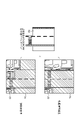
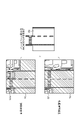
例えば、図8に示すように、自車両画像G1が取得され、事前撮影画像G2が読み込まれる。自車両画像G1は、俯瞰画像であり、他車両や障害物等の物体が存在しないフリースペースR1を有する。同様に、事前撮影画像G2も、俯瞰画像であり、他車両や障害物等の物体が存在しないフリースペースR2を有する。この事前撮影画像G2は、例えば、他車両や定点カメラ等により別日に撮像された画像である。
前述のステップS34では、自車両画像G1及び事前撮影画像G2のそれぞれの特徴点(共通特徴)が求められ、それらの特徴点から動きベクトルが求められる。詳しくは、自車両画像G1及び事前撮影画像G2において、フリースペースR1、R2のAND(論理積)領域、つまり共通領域だけが引き算される。まず、自車両画像G1及び事前撮影画像G2において、他車両や障害物等の物体が存在しない共通のフリースペース(共通領域)R3が求められる。そして、自車両画像G1のフリースペースR3内の特徴点が求められ、事前撮影画像G2のフリースペースR3内の特徴点が求められ、それらの特徴点の動きベクトル(移動量及び移動方向)が算出される。
図8の例では、自車両画像G1の車線(特徴)が、事前撮影画像G2の車線(特徴)に対して図8中の左右に広がっている。すなわち、撮像装置10の位置が設計位置に対して低くなっている。したがって、ステップS35において、車両沈み込みNGフラグが立てられる(車両沈み込みNGフラグ=1)。この場合、パンクや想定以上の過重が車両20にかかっている可能性がある。
図9の例では、自車両画像G1aの車線が、事前撮影画像G2の車線に対して図9中の左側にずれている。すなわち、撮像装置10の位置が設計位置に対して図9中の左側にずれている。したがって、ステップS37において、走行位置NGフラグが立てられる(走行位置NGフラグ=1)。この場合、車両20の走行位置が比較対象の事前撮影画像G2に比べて左側にずれている。
図10の例では、自車両画像G1bに、事前撮影画像G2に存在しないもの(図10中の△印)が存在している。したがって、ステップS40において、認識失敗被写体存在フラグが立てられる(認識失敗被写体存在フラグ=1)。この場合、物体(図10中の△印)がフリースペース検知で見逃されている。例えば、ロードコーン等の検知できない物体(被写体)が置かれている可能性がある。
図11の例では、自車両画像G1cに、事前撮影画像G2に存在しないもの(図11中の路面標識)が存在している。路面標識は、フリースペース検知において認識され、その路面標識の領域が差分処理から除外される。例えば、画像比較部14は、フリースペースR1に含まれる路面標識を画像処理により認識し、その路面標識の領域を除いて差分処理を実行する。路面標識は、車両20の走行に問題とならない。
図12の例では、自車両画像G1dに、事前撮影画像G2に存在しないもの(図12中の長方形)が存在している。したがって、ステップS40において、認識失敗被写体存在フラグが立てられる(認識失敗被写体存在フラグ=1)。この場合、物体(図12中の長方形)がフリースペース検知で路面標識として認識されない。例えば、路面標識以外の物体(被写体)が置かれている可能性がある。
<1-7.自動運転レベルの制御処理>
第1の実施形態に係る自動運転レベルの制御処理(変更処理)について説明する。この制御処理では、例えば、前述のフラグ(画像取得失敗フラグ、車両沈み込みNGフラグ、走行位置NGフラグ、認識失敗被写体存在フラグ)に応じて、自動運転レベルを制御する。例えば、レベル3の自動運転の実施が許可されている状況において、各フラグのいずれかが立てられると(フラグ=1)、自動運転レベルが下げられ、レベル3以上の自動運転の実施が禁止される。
第1の実施形態に係る自動運転レベルの制御処理(変更処理)について説明する。この制御処理では、例えば、前述のフラグ(画像取得失敗フラグ、車両沈み込みNGフラグ、走行位置NGフラグ、認識失敗被写体存在フラグ)に応じて、自動運転レベルを制御する。例えば、レベル3の自動運転の実施が許可されている状況において、各フラグのいずれかが立てられると(フラグ=1)、自動運転レベルが下げられ、レベル3以上の自動運転の実施が禁止される。
各測定ポイントで連続して画像取得失敗フラグ=1となる場合、撮像装置10の監視システム側に異常が生じた可能性があるため、制御部16は、異常がある旨をドライバに通知し、自動運転レベルをドライバがハンドルを握るハンズオン自動運転レベルに切り替える。例えば、制御部16は、自動運転レベルをレベル3からレベル2以下に変更する。つまり、レベル3以上の自動運転の実施が禁止され、レベル2以下の自動運転が許可される(以下も同様である)。
車両沈み込みNGフラグ=1である場合、例えば、ズレ量が一定の値より小さい場合、車両20は、前後の車両との車間を広めにとって自動走行する。一方、ズレ量が一定の値以上である場合、制御部16は、車両沈み込みが発生した旨をドライバに通知し、自動運転レベルをハンズオン自動運転レベルに切り替える。例えば、制御部16は、自動運転レベルをレベル3からレベル2以下に変更する。
走行位置NGフラグ=1である場合、車両20は、横方向の他車両や壁との車間を広めにとって自動走行する。一方、横方向の車間が確保できない場合、制御部16は、横方向の車間が確保できない旨をドライバに通知し、自動運転レベルをハンズオン自動運転レベルに切り替える。例えば、制御部16は、自動運転レベルをレベル3からレベル2以下に変更する。
認識失敗被写体存在フラグ=1である場合、制御部16は、他車両がこのフラグが発生した測定ポイントを通過する際、速度を落とすように設定し、自動運転レベルをハンズオン自動運転レベルに切り替える。例えば、制御部16は、自動運転レベルをレベル3からレベル2以下に変更する。
なお、サーバ側では、認識失敗被写体存在フラグが立っている画像を優先して人の目で解析し、原因対処を行う。例えば、道路に認識できない物体や標識があることが確認された場合、制御部16は、対策を施すまで、その測定ポイント周辺をルーティングから外したり、ルートに含める場合でもハンズオン自動運転領域としたりする。
また、各測定ポイントで連続して認識失敗被写体存在フラグ=1となる場合、撮像装置10の監視システム側に異常が生じた可能性があるため、制御部16は、異常がある旨をドライバに通知し、自動運転レベルをハンズオン自動運転レベルに切り替える。例えば、制御部16は、自動運転レベルをレベル3からレベル2以下に変更する。
なお、図13及び図14に示すように、認識できない物体(被写体)が画像G3内にある場合、制御部16は、その認識できない物体Rbが画像G3内にある旨をドライバに報告し、そのルートを自動運転のODD(Operational Design Domain)から外す。図13の例において物体Rbは馬車であり、図14の例において物体Rbは鹿である。
ここで、レベル3以上の自動運転の実施は、運行設計領域を表すODDに基づいて許可される。ODDは、設計上、自動運転システムが作動する前提となる走行環境条件(各種条件)のことであり、走行環境条件を満たす際に自動運転システムが正常に作動する。逆に、何らかの条件が欠けた場合は自動運転に支障をきたす恐れがあるため、運行停止措置や手動運転への切り替えが求められる。
自動運転レベルは、例えば、SAE(Society of Automotive Engineers)によって0から5までの6段階で定義されている。具体的には、自動運転レベルは、運転自動化なし(レベル0)、運転支援(レベル1)、部分的運転自動化(レベル2)、条件付運転自動化(レベル3)、高度運転自動化(レベル4)及び完全自動運転化(レベル5)に分類される。
レベル0(運転自動化なし)では、主体は運転者であり、走行領域(走行場所)は限定されない。このレベル0では、運転者が全ての動的運転タスクを実行する。
レベル1(運転支援)では、主体は運転者であり、走行領域は限定される。このレベル1では、運転自動化システムが動的運転タスクの縦方向・横方向のいずれか(両方同時ではない)の車両運動制御のサブタスクを特定の限定領域において持続的に実行する。この際、運転者は残りの動的運転タスクを実行することが期待される。例えば、レベル1では、アクセル、ブレーキ、ハンドル操作(右折・左折、車線を維持する)のいずれかを車が支援する。レベル1の自動運転機能の具体例としては、車間距離を一定に保つACC(アダプティブ・クルーズ・コントロール)、衝突被害軽減ブレーキ、レーンキープアシスト、車庫入れや駐車アシストがある。
レベル2(部分運転自動化)では、主体は運転者であり、走行領域は限定される。このレベル2では、運転自動化システムが動的運転タスクの縦方向及び横方向の車両運動制御のサブタスクを特定の限定領域において持続的に実行する。この際、運転者は、動的運転タスクのサブタスクである対象物・事象の検知及び応答を完了し、システムを監視することが期待される。例えば、レベル2では、アクセル、ブレーキ、ハンドル操作などの複数の操作を同時に車が支援する。レベル2の自動運転機能の具体例としては、ステアリングアシスト付きのACCがある。
レベル3(条件付き運転自動化)では、主体は車であり、走行領域は限定される。このレベル3では、運転自動化システムが全ての動的運転タスクを限定領域において持続的に実行する。この際、作動継続が困難な場合への応答準備ができている利用者は、他車両のシステムにおける動的運転タスク実行システムに関連するシステム故障だけではなく、自動運転システムが出した介入の要求を受け入れ、適切に応答することが期待される。例えば、レベル3では、特定の環境や条件下(例えば、高速道路上や、極限環境を除く天候下等)でのみ、システムが全ての運転操作(例えば、加速、操舵、制動)を行うが、緊急時等のシステムの要請時には運転者が運転操作を行う。
レベル4(高度運転自動化)では、主体は車であり、走行領域は限定される。このレベル4では、運転自動化システムが全ての動的運転タスク及び作業継続が困難な場合への応答を限定領域において持続的に実行する。作動継続が困難な場合、利用者が介入の要求に応答することは期待されない。例えば、レベル4では、特定の環境や条件下(例えば、高速道路上や、極限環境を除く天候下等)でのみ、システムが全ての運転操作(例えば、加速、操舵、制動)を行い、その条件が続く限り運転者が緊急時に対応せず、全く運転操作に関与しない。
レベル5(完全運転自動化)では、主体は車であり、走行領域は限定されない。このレベル5では、運転自動化システムが全ての動的運転タスク及び作業継続が困難な場合への応答を持続的かつ無制限に(限定領域内ではない)実行する。作動継続が困難な場合、利用者が介入の要求に応答することは期待されない。例えば、レベル5では、運転者が必要でなく、走行領域も限定されず、どんな場所の道路でも自動運転で走行が可能である。
なお、前述のように、自動運転レベルを0から5までの6段階で定義しているが、これに限るものではなく、例えば、7段階以上又は5段階以下で定義してもよい。また、自動運転レベル毎の内容も、前述と異なる内容に変えることも可能であり、適宜定義することが可能である。
<1-8.画像選択処理>
第1の実施形態に係る画像選択処理について図15及び図16を参照して説明する。図15は、第1の実施形態に係る画像選択処理の流れを示すフローチャートである。画像選択処理は、図4に示す自動運転処理中のステップS11の処理である。図16は、第1の実施形態に係る画像選択処理を説明するための説明図である。
第1の実施形態に係る画像選択処理について図15及び図16を参照して説明する。図15は、第1の実施形態に係る画像選択処理の流れを示すフローチャートである。画像選択処理は、図4に示す自動運転処理中のステップS11の処理である。図16は、第1の実施形態に係る画像選択処理を説明するための説明図である。
図15に示すように、画像処理部13は、車両20が測定ポイントまで所定距離Ymである時点から自車両画像の連続キャプチャ(連続取込)を開始し(ステップS51)、N=1とし、VMAX=0とする(ステップS52)。フレーム数はMである(フレームNo.1~M)。
画像比較部14は、フレームNo.=Nの画像(自車両画像)の中のフリースペース面積SNが所定の閾値D以上であるか否かを判断する(ステップS53)。画像比較部14は、フリースペース面積SNが所定の閾値D以上であると判断すると(ステップS53のYES)、フリースペース内の特徴量VNがVMAXより大きいか否かを判断する(ステップS54)。画像比較部14は、フリースペース内の特徴量VNがVMAXより大きいと判断すると、VMAX=VN、NVMAX=Nとする(ステップS55)。
一方、画像比較部14は、フリースペース面積SNが所定の閾値D以上でないと判断すると(ステップS53のNO)、又は、フリースペース内の特徴量VNがVMAXより大きくないと判断すると(ステップS54のNO)、そのまま処理をステップS56に進める。なお、フリースペース面積SNやフリースペース内の特徴量VNは、フリースペースに関するフリースペース情報の一例である。
画像比較部14は、N=Mであるか否かを判断する(ステップS56)。画像比較部14は、N=Mでないと判断すると(ステップS56のNO)、N=N+1とし(ステップS57)、処理をステップS53に戻す。一方、画像比較部14は、N=Mであると判断すると(ステップS56のYES)、フレームNo.=NVMAXの画像を伝送用データとして保持する(ステップS58)。
例えば、図16の例では、自車両画像の連続キャプチャにより、自車両画像が5枚(フレームNo.1~5:M=5)取得される。これらの自車両画像のフリースペース面積SNが求められ、そのフリースペース内の特徴量VNが求められる。フリースペース面積SNが所定の閾値D以上であり、特徴量VNが最大である画像(図16中の自車両画像のうち中央の自車両画像)が伝送用データとして保持される。これにより、フリースペース面積SNが所定の閾値D以上であり、特徴量VNが最大である画像を事前撮影画像として画像比較に用いることができる。一方、フリースペース面積SNが所定の閾値Dより小さい場合、そのフリースペース面積SNを有する自車両画像は伝送用データとして不合格となる。
なお、伝送用データに関して、フリースペース面積SNが所定の閾値D以上であり、特徴量VNが最大である画像以外にも、例えば、フリースペース面積SNが所定の閾値D以上であり、特徴量VNが所定の閾値以上である画像が伝送用データとして保存されてもよい。この特徴量VNが所定の閾値以上である画像は、1つ以上であればよく、1つでも複数でもよい。
<1-9.作用・効果>
以上説明したように、第1の実施形態によれば、自車両が走行する道路であって自車両画像(第1の画像)に含まれる道路上の第1のフリースペースR1と、あらかじめ求められた事前撮影画像(第2の画像)に含まれる道路上の第2のフリースペースR2との差分情報を取得し、その差分情報に基づき、自車両の自動運転レベルを制御する。これにより、他車両や障害物等の物体が存在しない各フリースペースR1、R2に基づいて差分情報が得られ、その差分情報に基づいて自動運転レベルが制御されるので、物体の存在を原因とする誤認識の発生を抑えることが可能であり、自動運転に係る制御を適切に行うことができる。
以上説明したように、第1の実施形態によれば、自車両が走行する道路であって自車両画像(第1の画像)に含まれる道路上の第1のフリースペースR1と、あらかじめ求められた事前撮影画像(第2の画像)に含まれる道路上の第2のフリースペースR2との差分情報を取得し、その差分情報に基づき、自車両の自動運転レベルを制御する。これにより、他車両や障害物等の物体が存在しない各フリースペースR1、R2に基づいて差分情報が得られ、その差分情報に基づいて自動運転レベルが制御されるので、物体の存在を原因とする誤認識の発生を抑えることが可能であり、自動運転に係る制御を適切に行うことができる。
また、第1の実施形態によれば、実際に撮像された画像を事前撮影画像として用いることによって、日々の変化(例えば、路面標識の設置や道路の陥没等)に対応することができる。これにより、日々の変化に対応して差分情報が得られ、その差分情報に基づいて自動運転レベルが制御されるので、日々の変化を原因とする誤認識の発生を抑えることが可能であり、自動運転に係る制御を適切に行うことができる。なお、シミュレーションにより生成された画像が比較対象である事前撮影画像として用いられると、日々の変化に対応することは難しく、その日々の変化を原因とする誤認識が生じることがある。
ここで、第1の実施形態においては、画像処理部13により画像内の物体(被写体)を認識し、その物体を避けて所定領域を検知することで、フリースペースR1、R2を検出することを例示したが、これに限るものではない。例えば、車両20の速度に応じ、図17に示すように、車両前方のエリアをフリースペースRとして検出するようにしてもよい。図17は、第1の実施形態に係るフリースペース検出の他の一例を説明するための説明図である。一例として、車両20の速度が80km/hである場合には、自車両の前方を走行する前車両に対するフリースペースRは80mとされる。なお、自動運転では、通常、車両20の速度に応じて車間を確保するため、自車両の前方を走行する前車両に対して一定の車間距離が存在する。
<2.第2の実施形態>
本開示に係る信号処理装置を適用した第2の実施形態に係る撮像システム1の概略構成例について図18を参照して説明する。図18は、第2の実施形態に係る撮像システム1の概略構成例を示すブロック図である。以下、第1の実施形態との相違点を中心に説明を行い、その他の説明を省略する。
本開示に係る信号処理装置を適用した第2の実施形態に係る撮像システム1の概略構成例について図18を参照して説明する。図18は、第2の実施形態に係る撮像システム1の概略構成例を示すブロック図である。以下、第1の実施形態との相違点を中心に説明を行い、その他の説明を省略する。
図18に示すように、第2の実施形態に係る撮像システム1は、撮像装置10Aと、処理装置10Bとを備える。撮像装置10Aは、光学系11と、撮像素子部12とを有する。処理装置10Bは、画像処理部13と、画像比較部14と、状況解析部15と、制御部16と、記憶部17と、車両情報接続部18と、ネットワーク接続部19とを有する。これらの撮像装置10Aと処理装置10Bとは、有線又は無線により互いに通信可能に形成されている。なお、前述の撮像装置10Aに他の制御部を設けるようにしてもよい。
以上説明したように、第2の実施形態によれば、撮像装置10Aと処理装置10Bとを別体にすることによって、撮像装置10Aの小型化を実現することが可能となる。これにより、撮像装置10Aの設置自由度を上げ、ユーザの利便性を向上させることができる。なお、第2の実施形態によれば、第1の実施形態と同じ効果を得ることができる。
<3.第3の実施形態>
本開示に係る信号処理装置を適用した第3の実施形態に係る撮像システム1Aの概略構成例について図19を参照して説明する。図19は、第3の実施形態に係る撮像システム1Aの概略構成例を示すブロック図である。以下、第1の実施形態との相違点を中心に説明を行い、その他の説明を省略する。
本開示に係る信号処理装置を適用した第3の実施形態に係る撮像システム1Aの概略構成例について図19を参照して説明する。図19は、第3の実施形態に係る撮像システム1Aの概略構成例を示すブロック図である。以下、第1の実施形態との相違点を中心に説明を行い、その他の説明を省略する。
図19に示すように、第3の実施形態に係る撮像システム1Aは、撮像装置10Cと、処理装置10Dとを備える。撮像装置10Cは、光学系11と、撮像素子部12と、画像処理部13とを有する。処理装置10Dは、画像比較部14と、状況解析部15と、制御部16と、記憶部17と、車両情報接続部18と、ネットワーク接続部19とを有する。これらの撮像装置10Cと処理装置10Dとは、有線又は無線により互いに通信可能に形成されている。なお、前述の撮像装置10Cに他の制御部を設けるようにしてもよい。
以上説明したように、第3の実施形態によれば、撮像装置10Cと処理装置10Dとを別体にすることによって、撮像装置10Cの小型化を実現することが可能となる。これにより、撮像装置10Cの設置自由度を上げ、ユーザの利便性を向上させることができる。なお、第3の実施形態によれば、第1の実施形態と同じ効果を得ることができる。
なお、第3の実施形態においては、撮像装置10Cに画像処理部13を設けることを例示したが、これに限るものではない。例えば、撮像装置10Cに画像比較部14、状況解析部15、制御部16、記憶部17のいずれか一つ又は複数を設けるようにしてもよい。つまり、撮像装置10C及び処理装置10Dに対し、画像処理部13、画像比較部14、状況解析部15、制御部16及び記憶部17を適宜振り分けて設けることが可能である。
<4.他の実施形態>
前述の各実施形態においては、測定ポイントに応じ、自車両画像と事前撮影画像とを1フレームで比較することを例示したが、これに限るものではない。例えば、測定ポイントの前後も含め、自車両画像と事前撮影画像とを連続する複数フレームで比較するようにしてもよい。この場合、測定ポイントの前後に対応する各事前撮影画像も、あらかじめ記憶されている。
前述の各実施形態においては、測定ポイントに応じ、自車両画像と事前撮影画像とを1フレームで比較することを例示したが、これに限るものではない。例えば、測定ポイントの前後も含め、自車両画像と事前撮影画像とを連続する複数フレームで比較するようにしてもよい。この場合、測定ポイントの前後に対応する各事前撮影画像も、あらかじめ記憶されている。
また、前述の各実施形態においては、差分情報に基づいて自動運転レベルを制御することを例示したが、これに限るものではない。例えば、差分情報に基づいて自車両の速度及び車間距離(自車両と他車両との離間距離)のどちらか一方又は両方を制御部16により制御するようにしてもよい。この場合、自動運転レベルの制御に加え、自車両の速度及び車間距離のどちらか一方又は両方を制御することが可能である。あるいは、自車両の速度及び車間距離のどちらか一方又は両方を単独で制御することが可能である。
また、前述の各実施形態においては、撮像装置10によりフリースペース検知(例えば、フリースペース検知は障害物や路面標識の認識等も含む)を実行することを例示したが、これに限るものではない。例えば、他のカメラによりフリースペース検知を実行するようにしてもよい。この場合には、他のカメラにより検知された検知結果(認識結果)がカメラ位置情報と共に撮像装置10に送信される。また、フリースペース検知のため、LiDAR(Light Detection and Ranging、Laser Imaging Detection and Ranging)やレーダ等のカメラ以外の検出装置を用いることも可能である。
また、前述の各実施形態においては、車両20が測定ポイント(該当地点)に近づいたタイミング(測定ポイントから所定距離の位置)で比較対象となる事前撮影画像を受信することを例示したが、これに限るものではない。例えば、事前撮影画像を走行前のルーティング(ルート設定)時にダウンロードによりあらかじめ受信してもよい。事前撮影画像を事前に受信することで、トンネル等の電波が届かず受信不可能な場所でも、比較処理を行うことができる。
また、ルーティングに関して、事前撮影画像があるルートを優先的に選んでルーティングを行ってもよい。また、事前撮影画像は、他車両により撮影された画像でもよい。事前撮影画像は、サーバから受信されてもよく、あるいは、事前撮影画像を蓄積する路上装置から受信されてもよい。ルートが良く通る道である場合には、自車両画像を事前撮像画像として保存しておき、比較対象として使用することで、道路の劣化等を正確に検出することができる。画像内の車線(白線等)は、そのまま画像比較により差分が取られてもよく、あるいは、車線が不要となる場合には、車線を認識してマスクし、比較対象から外してもよい。比較結果の差分が認識できない立体物や路面標識である場合、その画像をサーバに送信し、機械学習システムにおいて、その画像を認識できるように学習するための教師データとして使用してもよい。
また、前述の撮像装置10を、自車両の状態をより精度よく監視するため、前方を向いたカメラだけではなく、側方や後方を向いたカメラに適用することが可能である。また、撮像装置10を、カメラ以外、例えば、ドライブレコーダや携帯端末等の電子機器に適用することが可能である。この電子機器は車両20に取り付けられる。
以上、本開示の実施形態について説明したが、本開示の技術的範囲は、上述の実施形態そのままに限定されるものではなく、本開示の要旨を逸脱しない範囲において種々の変更が可能である。また、異なる実施形態及び変形例にわたる構成要素を適宜組み合わせてもよい。
また、本明細書に記載された各実施形態における効果はあくまで例示であって限定されるものでは無く、他の効果があってもよい。
<5.付記>
なお、本技術は以下のような構成も取ることができる。
(1)
車両が走行する道路であって第1の画像中の前記道路上の第1のフリースペースと、あらかじめ求められた第2の画像中の前記道路上の第2のフリースペースとの差分情報を取得する画像比較部と、
前記差分情報に基づき、前記車両の自動運転レベルを制御する制御部と、
を備える信号処理装置。
(2)
前記第1の画像から前記第1のフリースペースを検出し、前記第2の画像から前記第2のフリースペースを検出する画像処理部をさらに備える、
上記(1)に記載の信号処理装置。
(3)
前記第1のフリースペース及び前記第2のフリースペースは、
互いに共通領域を有し、
前記差分情報は、
前記第1のフリースペースの前記共通領域と前記第2のフリースペースの前記共通領域との差分量を含む、
上記(1)又は(2)に記載の信号処理装置。
(4)
前記差分情報に基づき、前記車両の状況を解析する状況解析部をさらに備え、
前記制御部は、
前記車両の状況に応じ、前記車両の自動運転レベルを制御する、
上記(1)から(3)のいずれか一つに記載の信号処理装置。
(5)
前記第1のフリースペース及び前記第2のフリースペースは、
互いに共通特徴を有し、
前記差分情報は、
前記第1のフリースペースの前記共通特徴と前記第2のフリースペースの前記共通特徴との移動量及び移動方向を含む、
上記(4)に記載の信号処理装置。
(6)
前記状況解析部は、
前記車両の状況として、前記第1の画像の取得失敗、前記車両の沈み込み、前記車両の走行位置異常又は前記第1の画像の認識失敗を解析し、
前記制御部は、
前記状況解析部が前記第1の画像の取得失敗、前記車両の沈み込み、前記車両の走行位置異常又は前記第1の画像の認識失敗を認識した場合、前記車両の自動運転レベルを下げる、
上記(4)又は(5)に記載の信号処理装置。
(7)
前記制御部は、
前記第1の画像を取得する画像取得ポイントから前記車両が所定距離の位置にある場合、前記車両の自動運転レベルを、前記第1の画像を取得するための測定用自動運転レベルに移行する、
上記(1)から(6)のいずれか一つに記載の信号処理装置。
(8)
前記制御部は、
前記第1の画像を取得する画像取得ポイントに対応する前記第2の画像がない場合、前記車両の測定用自動運転レベルを元の前記車両の自動運転レベルに移行する、
上記(7)に記載の信号処理装置。
(9)
前記画像比較部は、
前記第1の画像を取得する画像取得ポイントから前記車両が所定距離の位置にある時点から前記第1の画像を繰り返し取り込み、取り込んだ複数の前記第1の画像の中から1つ以上の前記第1の画像を選択して用いる、
上記(1)から(8)のいずれか一つに記載の信号処理装置。
(10)
前記画像比較部は、
取り込んだ複数の前記第1の画像と前記第2の画像との個々の差分情報を取得し、
取得した前記個々の差分情報に基づき、取り込んだ複数の前記第1の画像の中から1つ以上の前記第1の画像を選択する、
上記(9)に記載の信号処理装置。
(11)
前記個々の差分情報は、
それぞれ前記第1のフリースペースと前記第2のフリースペースとの差分量であり、
前記画像比較部は、
前記差分量が所定の閾値以上である1つ以上の前記第1の画像を選択する、
上記(10)に記載の信号処理装置。
(12)
前記画像比較部は、
用いた1つ以上の前記第1の画像を前記第2の画像として保存する、
上記(9)から(11)のいずれか一つに記載の信号処理装置。
(13)
前記画像比較部は、
前記第1の画像を取得する画像取得ポイントから前記車両が所定距離の位置にある時点から前記第1の画像を繰り返し取り込み、取り込んだ複数の前記第1の画像の中から1つ以上の前記第1の画像を選択して保存する、
上記(1)から(12)のいずれか一つに記載の信号処理装置。
(14)
前記画像比較部は、
取り込んだ前記第1の画像ごとの前記第1のフリースペースに関するフリースペース情報を取得し、
取得した前記第1の画像ごとの前記フリースペース情報に基づき、取り込んだ複数の前記第1の画像の中から1つ以上の前記第1の画像を選択する、
上記(13)に記載の信号処理装置。
(15)
前記第1の画像ごとの前記フリースペース情報は、
それぞれ前記第1のフリースペースの面積であり、
前記画像比較部は、
前記面積が所定の閾値以上である1つ以上の前記第1の画像を選択する、
上記(14)に記載の信号処理装置。
(16)
前記第1の画像ごとの前記フリースペース情報は、
それぞれ前記第1のフリースペースの特徴量であり、
前記画像比較部は、
前記特徴量が所定の閾値以上である1つ以上の前記第1の画像を選択する、
上記(14)又は(15)に記載の信号処理装置。
(17)
前記画像比較部は、
前記第1のフリースペースに含まれる路面標識の領域を除いて前記差分情報を取得する、
上記(1)から(16)のいずれか一つに記載の信号処理装置。
(18)
前記第1の画像及び前記第2の画像は、
所定の仮想視点から得られる俯瞰画像である、
上記(1)から(17)のいずれか一つに記載の信号処理装置。
(19)
前記制御部は、
前記車両の速度及び車間距離のどちらか一方又は両方を制御する、
上記(1)から(18)のいずれか一つに記載の信号処理装置。
(20)
車両が走行する道路であって第1の画像中の前記道路上の第1のフリースペースと、あらかじめ求められた第2の画像中の前記道路上の第2のフリースペースとの差分情報を取得し、
前記差分情報に基づき、前記車両の自動運転レベルを制御する、
信号処理方法。
(21)
上記(1)から(19)のいずれか一つに記載の信号処理装置を用いる、
信号処理方法。
なお、本技術は以下のような構成も取ることができる。
(1)
車両が走行する道路であって第1の画像中の前記道路上の第1のフリースペースと、あらかじめ求められた第2の画像中の前記道路上の第2のフリースペースとの差分情報を取得する画像比較部と、
前記差分情報に基づき、前記車両の自動運転レベルを制御する制御部と、
を備える信号処理装置。
(2)
前記第1の画像から前記第1のフリースペースを検出し、前記第2の画像から前記第2のフリースペースを検出する画像処理部をさらに備える、
上記(1)に記載の信号処理装置。
(3)
前記第1のフリースペース及び前記第2のフリースペースは、
互いに共通領域を有し、
前記差分情報は、
前記第1のフリースペースの前記共通領域と前記第2のフリースペースの前記共通領域との差分量を含む、
上記(1)又は(2)に記載の信号処理装置。
(4)
前記差分情報に基づき、前記車両の状況を解析する状況解析部をさらに備え、
前記制御部は、
前記車両の状況に応じ、前記車両の自動運転レベルを制御する、
上記(1)から(3)のいずれか一つに記載の信号処理装置。
(5)
前記第1のフリースペース及び前記第2のフリースペースは、
互いに共通特徴を有し、
前記差分情報は、
前記第1のフリースペースの前記共通特徴と前記第2のフリースペースの前記共通特徴との移動量及び移動方向を含む、
上記(4)に記載の信号処理装置。
(6)
前記状況解析部は、
前記車両の状況として、前記第1の画像の取得失敗、前記車両の沈み込み、前記車両の走行位置異常又は前記第1の画像の認識失敗を解析し、
前記制御部は、
前記状況解析部が前記第1の画像の取得失敗、前記車両の沈み込み、前記車両の走行位置異常又は前記第1の画像の認識失敗を認識した場合、前記車両の自動運転レベルを下げる、
上記(4)又は(5)に記載の信号処理装置。
(7)
前記制御部は、
前記第1の画像を取得する画像取得ポイントから前記車両が所定距離の位置にある場合、前記車両の自動運転レベルを、前記第1の画像を取得するための測定用自動運転レベルに移行する、
上記(1)から(6)のいずれか一つに記載の信号処理装置。
(8)
前記制御部は、
前記第1の画像を取得する画像取得ポイントに対応する前記第2の画像がない場合、前記車両の測定用自動運転レベルを元の前記車両の自動運転レベルに移行する、
上記(7)に記載の信号処理装置。
(9)
前記画像比較部は、
前記第1の画像を取得する画像取得ポイントから前記車両が所定距離の位置にある時点から前記第1の画像を繰り返し取り込み、取り込んだ複数の前記第1の画像の中から1つ以上の前記第1の画像を選択して用いる、
上記(1)から(8)のいずれか一つに記載の信号処理装置。
(10)
前記画像比較部は、
取り込んだ複数の前記第1の画像と前記第2の画像との個々の差分情報を取得し、
取得した前記個々の差分情報に基づき、取り込んだ複数の前記第1の画像の中から1つ以上の前記第1の画像を選択する、
上記(9)に記載の信号処理装置。
(11)
前記個々の差分情報は、
それぞれ前記第1のフリースペースと前記第2のフリースペースとの差分量であり、
前記画像比較部は、
前記差分量が所定の閾値以上である1つ以上の前記第1の画像を選択する、
上記(10)に記載の信号処理装置。
(12)
前記画像比較部は、
用いた1つ以上の前記第1の画像を前記第2の画像として保存する、
上記(9)から(11)のいずれか一つに記載の信号処理装置。
(13)
前記画像比較部は、
前記第1の画像を取得する画像取得ポイントから前記車両が所定距離の位置にある時点から前記第1の画像を繰り返し取り込み、取り込んだ複数の前記第1の画像の中から1つ以上の前記第1の画像を選択して保存する、
上記(1)から(12)のいずれか一つに記載の信号処理装置。
(14)
前記画像比較部は、
取り込んだ前記第1の画像ごとの前記第1のフリースペースに関するフリースペース情報を取得し、
取得した前記第1の画像ごとの前記フリースペース情報に基づき、取り込んだ複数の前記第1の画像の中から1つ以上の前記第1の画像を選択する、
上記(13)に記載の信号処理装置。
(15)
前記第1の画像ごとの前記フリースペース情報は、
それぞれ前記第1のフリースペースの面積であり、
前記画像比較部は、
前記面積が所定の閾値以上である1つ以上の前記第1の画像を選択する、
上記(14)に記載の信号処理装置。
(16)
前記第1の画像ごとの前記フリースペース情報は、
それぞれ前記第1のフリースペースの特徴量であり、
前記画像比較部は、
前記特徴量が所定の閾値以上である1つ以上の前記第1の画像を選択する、
上記(14)又は(15)に記載の信号処理装置。
(17)
前記画像比較部は、
前記第1のフリースペースに含まれる路面標識の領域を除いて前記差分情報を取得する、
上記(1)から(16)のいずれか一つに記載の信号処理装置。
(18)
前記第1の画像及び前記第2の画像は、
所定の仮想視点から得られる俯瞰画像である、
上記(1)から(17)のいずれか一つに記載の信号処理装置。
(19)
前記制御部は、
前記車両の速度及び車間距離のどちらか一方又は両方を制御する、
上記(1)から(18)のいずれか一つに記載の信号処理装置。
(20)
車両が走行する道路であって第1の画像中の前記道路上の第1のフリースペースと、あらかじめ求められた第2の画像中の前記道路上の第2のフリースペースとの差分情報を取得し、
前記差分情報に基づき、前記車両の自動運転レベルを制御する、
信号処理方法。
(21)
上記(1)から(19)のいずれか一つに記載の信号処理装置を用いる、
信号処理方法。
1 撮像システム
1A 撮像システム
10 撮像装置
11 光学系
12 撮像素子部
13 画像処理部
14 画像比較部
15 状況解析部
16 制御部
17 記憶部
18 車両情報接続部
19 ネットワーク接続部
20 車両
30 データベース
G 画像
Ga 俯瞰画像
G1 自車両画像
G1a~G1d 自車両画像
G2 事前撮影画像
G3 画像
R フリースペース
Ra フリースペース
R1~R3 フリースペース
1A 撮像システム
10 撮像装置
11 光学系
12 撮像素子部
13 画像処理部
14 画像比較部
15 状況解析部
16 制御部
17 記憶部
18 車両情報接続部
19 ネットワーク接続部
20 車両
30 データベース
G 画像
Ga 俯瞰画像
G1 自車両画像
G1a~G1d 自車両画像
G2 事前撮影画像
G3 画像
R フリースペース
Ra フリースペース
R1~R3 フリースペース
Claims (20)
- 車両が走行する道路であって第1の画像中の前記道路上の第1のフリースペースと、あらかじめ求められた第2の画像中の前記道路上の第2のフリースペースとの差分情報を取得する画像比較部と、
前記差分情報に基づき、前記車両の自動運転レベルを制御する制御部と、
を備える信号処理装置。 - 前記第1の画像から前記第1のフリースペースを検出し、前記第2の画像から前記第2のフリースペースを検出する画像処理部をさらに備える、
請求項1に記載の信号処理装置。 - 前記第1のフリースペース及び前記第2のフリースペースは、
互いに共通領域を有し、
前記差分情報は、
前記第1のフリースペースの前記共通領域と前記第2のフリースペースの前記共通領域との差分量を含む、
請求項1に記載の信号処理装置。 - 前記差分情報に基づき、前記車両の状況を解析する状況解析部をさらに備え、
前記制御部は、
前記車両の状況に応じ、前記車両の自動運転レベルを制御する、
請求項1に記載の信号処理装置。 - 前記第1のフリースペース及び前記第2のフリースペースは、
互いに共通特徴を有し、
前記差分情報は、
前記第1のフリースペースの前記共通特徴と前記第2のフリースペースの前記共通特徴との移動量及び移動方向を含む、
請求項4に記載の信号処理装置。 - 前記状況解析部は、
前記車両の状況として、前記第1の画像の取得失敗、前記車両の沈み込み、前記車両の走行位置異常又は前記第1の画像の認識失敗を解析し、
前記制御部は、
前記状況解析部が前記第1の画像の取得失敗、前記車両の沈み込み、前記車両の走行位置異常又は前記第1の画像の認識失敗を認識した場合、前記車両の自動運転レベルを下げる、
請求項4に記載の信号処理装置。 - 前記制御部は、
前記第1の画像を取得する画像取得ポイントから前記車両が所定距離の位置にある場合、前記車両の自動運転レベルを、前記第1の画像を取得するための測定用自動運転レベルに移行する、
請求項1に記載の信号処理装置。 - 前記制御部は、
前記第1の画像を取得する画像取得ポイントに対応する前記第2の画像がない場合、前記車両の測定用自動運転レベルを元の前記車両の自動運転レベルに移行する、
請求項7に記載の信号処理装置。 - 前記画像比較部は、
前記第1の画像を取得する画像取得ポイントから前記車両が所定距離の位置にある時点から前記第1の画像を繰り返し取り込み、取り込んだ複数の前記第1の画像の中から1つ以上の前記第1の画像を選択して用いる、
請求項1に記載の信号処理装置。 - 前記画像比較部は、
取り込んだ複数の前記第1の画像と前記第2の画像との個々の差分情報を取得し、
取得した前記個々の差分情報に基づき、取り込んだ複数の前記第1の画像の中から1つ以上の前記第1の画像を選択する、
請求項9に記載の信号処理装置。 - 前記個々の差分情報は、
それぞれ前記第1のフリースペースと前記第2のフリースペースとの差分量であり、
前記画像比較部は、
前記差分量が所定の閾値以上である1つ以上の前記第1の画像を選択する、
請求項10に記載の信号処理装置。 - 前記画像比較部は、
用いた1つ以上の前記第1の画像を前記第2の画像として保存する、
請求項9に記載の信号処理装置。 - 前記画像比較部は、
前記第1の画像を取得する画像取得ポイントから前記車両が所定距離の位置にある時点から前記第1の画像を繰り返し取り込み、取り込んだ複数の前記第1の画像の中から1つ以上の前記第1の画像を選択して保存する、
請求項1に記載の信号処理装置。 - 前記画像比較部は、
取り込んだ前記第1の画像ごとの前記第1のフリースペースに関するフリースペース情報を取得し、
取得した前記第1の画像ごとの前記フリースペース情報に基づき、取り込んだ複数の前記第1の画像の中から1つ以上の前記第1の画像を選択する、
請求項13に記載の信号処理装置。 - 前記第1の画像ごとの前記フリースペース情報は、
それぞれ前記第1のフリースペースの面積であり、
前記画像比較部は、
前記面積が所定の閾値以上である1つ以上の前記第1の画像を選択する、
請求項14に記載の信号処理装置。 - 前記第1の画像ごとの前記フリースペース情報は、
それぞれ前記第1のフリースペースの特徴量であり、
前記画像比較部は、
前記特徴量が所定の閾値以上である1つ以上の前記第1の画像を選択する、
請求項14に記載の信号処理装置。 - 前記画像比較部は、
前記第1のフリースペースに含まれる路面標識の領域を除いて前記差分情報を取得する、
請求項1に記載の信号処理装置。 - 前記第1の画像及び前記第2の画像は、
所定の仮想視点から得られる俯瞰画像である、
請求項1に記載の信号処理装置。 - 前記制御部は、
前記車両の速度及び車間距離のどちらか一方又は両方を制御する、
請求項1に記載の信号処理装置。 - 車両が走行する道路であって第1の画像中の前記道路上の第1のフリースペースと、あらかじめ求められた第2の画像中の前記道路上の第2のフリースペースとの差分情報を取得し、
前記差分情報に基づき、前記車両の自動運転レベルを制御する、
信号処理方法。
Priority Applications (1)
| Application Number | Priority Date | Filing Date | Title |
|---|---|---|---|
| US18/251,711 US20240010242A1 (en) | 2020-11-11 | 2021-10-28 | Signal processing device and signal processing method |
Applications Claiming Priority (2)
| Application Number | Priority Date | Filing Date | Title |
|---|---|---|---|
| JP2020-187907 | 2020-11-11 | ||
| JP2020187907 | 2020-11-11 |
Publications (1)
| Publication Number | Publication Date |
|---|---|
| WO2022102425A1 true WO2022102425A1 (ja) | 2022-05-19 |
Family
ID=81601058
Family Applications (1)
| Application Number | Title | Priority Date | Filing Date |
|---|---|---|---|
| PCT/JP2021/039814 Ceased WO2022102425A1 (ja) | 2020-11-11 | 2021-10-28 | 信号処理装置及び信号処理方法 |
Country Status (2)
| Country | Link |
|---|---|
| US (1) | US20240010242A1 (ja) |
| WO (1) | WO2022102425A1 (ja) |
Cited By (1)
| Publication number | Priority date | Publication date | Assignee | Title |
|---|---|---|---|---|
| WO2025051448A1 (de) * | 2023-09-05 | 2025-03-13 | Valeo Schalter Und Sensoren Gmbh | Verfahren zum durchführen eines parkvorgangs eines fahrzeugs maximal mit einem autonomielevel 3, sowie elektronisches parkassistenzsystem |
Families Citing this family (1)
| Publication number | Priority date | Publication date | Assignee | Title |
|---|---|---|---|---|
| JP2025118192A (ja) * | 2024-01-31 | 2025-08-13 | トヨタ自動車株式会社 | データ収集装置、データ収集方法及びプログラム |
Citations (3)
| Publication number | Priority date | Publication date | Assignee | Title |
|---|---|---|---|---|
| JP2017126835A (ja) * | 2016-01-12 | 2017-07-20 | 株式会社デンソー | 車載カメラのレンズ異常検出装置 |
| JP2017165322A (ja) * | 2016-03-17 | 2017-09-21 | 株式会社デンソー | 走行支援装置 |
| JP2019121030A (ja) * | 2017-12-28 | 2019-07-22 | 株式会社デンソーテン | カメラずれ検出装置、カメラずれ検出方法および異常検出装置 |
Family Cites Families (7)
| Publication number | Priority date | Publication date | Assignee | Title |
|---|---|---|---|---|
| EP3647728B1 (en) * | 2018-11-05 | 2023-06-21 | Toyota Jidosha Kabushiki Kaisha | Map information system |
| JP7211047B2 (ja) * | 2018-12-04 | 2023-01-24 | 株式会社アイシン | 路面検出装置および路面検出プログラム |
| US20200217667A1 (en) * | 2019-01-08 | 2020-07-09 | Qualcomm Incorporated | Robust association of traffic signs with a map |
| JP7327992B2 (ja) * | 2019-05-10 | 2023-08-16 | フォルシアクラリオン・エレクトロニクス株式会社 | 立体物検出装置、及び立体物検出方法 |
| US11556127B2 (en) * | 2020-04-03 | 2023-01-17 | Baidu Usa Llc | Static obstacle map based perception system |
| JP7191065B2 (ja) * | 2020-07-06 | 2022-12-16 | 本田技研工業株式会社 | 処理装置、処理方法、およびプログラム |
| US11884265B1 (en) * | 2020-11-02 | 2024-01-30 | Nissan Motor Co., Ltd. | Parking assistance method and parking assistance device |
-
2021
- 2021-10-28 WO PCT/JP2021/039814 patent/WO2022102425A1/ja not_active Ceased
- 2021-10-28 US US18/251,711 patent/US20240010242A1/en not_active Abandoned
Patent Citations (3)
| Publication number | Priority date | Publication date | Assignee | Title |
|---|---|---|---|---|
| JP2017126835A (ja) * | 2016-01-12 | 2017-07-20 | 株式会社デンソー | 車載カメラのレンズ異常検出装置 |
| JP2017165322A (ja) * | 2016-03-17 | 2017-09-21 | 株式会社デンソー | 走行支援装置 |
| JP2019121030A (ja) * | 2017-12-28 | 2019-07-22 | 株式会社デンソーテン | カメラずれ検出装置、カメラずれ検出方法および異常検出装置 |
Cited By (1)
| Publication number | Priority date | Publication date | Assignee | Title |
|---|---|---|---|---|
| WO2025051448A1 (de) * | 2023-09-05 | 2025-03-13 | Valeo Schalter Und Sensoren Gmbh | Verfahren zum durchführen eines parkvorgangs eines fahrzeugs maximal mit einem autonomielevel 3, sowie elektronisches parkassistenzsystem |
Also Published As
| Publication number | Publication date |
|---|---|
| US20240010242A1 (en) | 2024-01-11 |
Similar Documents
| Publication | Publication Date | Title |
|---|---|---|
| JP7314798B2 (ja) | 撮像装置、画像処理装置、及び、画像処理方法 | |
| EP3602220B1 (en) | Dynamic sensor selection for self-driving vehicles | |
| US11327485B2 (en) | Control device for vehicle, and vehicle | |
| EP3900997B1 (en) | Method of and system for controlling operation of self-driving car | |
| US11726212B2 (en) | Detector for point cloud fusion | |
| US12227179B2 (en) | Vehicle control device and vehicle control method | |
| CN114103946A (zh) | 用于免提驾驶的动态停止时间阈值选择 | |
| JP4483305B2 (ja) | 車両周辺監視装置 | |
| JP6103265B2 (ja) | 車両用歩行者画像取得装置 | |
| US12275429B2 (en) | Mobile object control device, mobile object control method, and storage medium | |
| JP7433146B2 (ja) | 物体検出方法及び物体検出装置 | |
| US12549867B2 (en) | Imaging device and image processing method | |
| US11891093B2 (en) | Control device, control method, and storage medium for controlling a mobile device along a conditions-varying travel path | |
| CN116524016A (zh) | 图像处理装置及方法、移动体控制装置、以及存储介质 | |
| WO2022102425A1 (ja) | 信号処理装置及び信号処理方法 | |
| US12266192B2 (en) | Traffic light detection and classification for autonomous driving vehicles | |
| US12434696B2 (en) | Trajectory generation device, trajectory generation method, and computer program product | |
| CN112567427B (zh) | 图像处理装置、图像处理方法和程序 | |
| US11613275B2 (en) | Grayscale-based camera perception | |
| JP7491023B2 (ja) | 管制装置、及び管制システム | |
| CN114911219B (zh) | 一种用于视觉传感器的控制指令生成方法及装置、控制方法及装置 | |
| JP7371679B2 (ja) | 情報処理装置、情報処理方法及び情報処理プログラム | |
| JP7589133B2 (ja) | 車両用制御装置 | |
| US20260070554A1 (en) | Mobile object control device, mobile object control method, and storage medium |
Legal Events
| Date | Code | Title | Description |
|---|---|---|---|
| 121 | Ep: the epo has been informed by wipo that ep was designated in this application |
Ref document number: 21891672 Country of ref document: EP Kind code of ref document: A1 |
|
| WWE | Wipo information: entry into national phase |
Ref document number: 18251711 Country of ref document: US |
|
| NENP | Non-entry into the national phase |
Ref country code: DE |
|
| 122 | Ep: pct application non-entry in european phase |
Ref document number: 21891672 Country of ref document: EP Kind code of ref document: A1 |
|
| NENP | Non-entry into the national phase |
Ref country code: JP |