WO2022097478A1 - 効果制御方法、制御システムおよび端末装置 - Google Patents
効果制御方法、制御システムおよび端末装置 Download PDFInfo
- Publication number
- WO2022097478A1 WO2022097478A1 PCT/JP2021/038835 JP2021038835W WO2022097478A1 WO 2022097478 A1 WO2022097478 A1 WO 2022097478A1 JP 2021038835 W JP2021038835 W JP 2021038835W WO 2022097478 A1 WO2022097478 A1 WO 2022097478A1
- Authority
- WO
- WIPO (PCT)
- Prior art keywords
- effect
- control
- display mode
- value
- terminal device
- Prior art date
- Legal status (The legal status is an assumption and is not a legal conclusion. Google has not performed a legal analysis and makes no representation as to the accuracy of the status listed.)
- Ceased
Links
Images




Classifications
-
- H—ELECTRICITY
- H05—ELECTRIC TECHNIQUES NOT OTHERWISE PROVIDED FOR
- H05B—ELECTRIC HEATING; ELECTRIC LIGHT SOURCES NOT OTHERWISE PROVIDED FOR; CIRCUIT ARRANGEMENTS FOR ELECTRIC LIGHT SOURCES, IN GENERAL
- H05B47/00—Circuit arrangements for operating light sources in general, i.e. where the type of light source is not relevant
- H05B47/10—Controlling the light source
- H05B47/175—Controlling the light source by remote control
- H05B47/19—Controlling the light source by remote control via wireless transmission
-
- H—ELECTRICITY
- H05—ELECTRIC TECHNIQUES NOT OTHERWISE PROVIDED FOR
- H05B—ELECTRIC HEATING; ELECTRIC LIGHT SOURCES NOT OTHERWISE PROVIDED FOR; CIRCUIT ARRANGEMENTS FOR ELECTRIC LIGHT SOURCES, IN GENERAL
- H05B45/00—Circuit arrangements for operating light-emitting diodes [LED]
- H05B45/20—Controlling the colour of the light
-
- H—ELECTRICITY
- H05—ELECTRIC TECHNIQUES NOT OTHERWISE PROVIDED FOR
- H05B—ELECTRIC HEATING; ELECTRIC LIGHT SOURCES NOT OTHERWISE PROVIDED FOR; CIRCUIT ARRANGEMENTS FOR ELECTRIC LIGHT SOURCES, IN GENERAL
- H05B47/00—Circuit arrangements for operating light sources in general, i.e. where the type of light source is not relevant
- H05B47/10—Controlling the light source
- H05B47/165—Controlling the light source following a pre-assigned programmed sequence; Logic control [LC]
-
- H—ELECTRICITY
- H05—ELECTRIC TECHNIQUES NOT OTHERWISE PROVIDED FOR
- H05B—ELECTRIC HEATING; ELECTRIC LIGHT SOURCES NOT OTHERWISE PROVIDED FOR; CIRCUIT ARRANGEMENTS FOR ELECTRIC LIGHT SOURCES, IN GENERAL
- H05B47/00—Circuit arrangements for operating light sources in general, i.e. where the type of light source is not relevant
- H05B47/10—Controlling the light source
- H05B47/175—Controlling the light source by remote control
- H05B47/196—Controlling the light source by remote control characterised by user interface arrangements
- H05B47/1965—Controlling the light source by remote control characterised by user interface arrangements using handheld communication devices
-
- H—ELECTRICITY
- H05—ELECTRIC TECHNIQUES NOT OTHERWISE PROVIDED FOR
- H05B—ELECTRIC HEATING; ELECTRIC LIGHT SOURCES NOT OTHERWISE PROVIDED FOR; CIRCUIT ARRANGEMENTS FOR ELECTRIC LIGHT SOURCES, IN GENERAL
- H05B47/00—Circuit arrangements for operating light sources in general, i.e. where the type of light source is not relevant
- H05B47/10—Controlling the light source
- H05B47/175—Controlling the light source by remote control
- H05B47/198—Grouping of control procedures or address assignation to light sources
- H05B47/1985—Creation of lighting zones or scenes
-
- Y—GENERAL TAGGING OF NEW TECHNOLOGICAL DEVELOPMENTS; GENERAL TAGGING OF CROSS-SECTIONAL TECHNOLOGIES SPANNING OVER SEVERAL SECTIONS OF THE IPC; TECHNICAL SUBJECTS COVERED BY FORMER USPC CROSS-REFERENCE ART COLLECTIONS [XRACs] AND DIGESTS
- Y02—TECHNOLOGIES OR APPLICATIONS FOR MITIGATION OR ADAPTATION AGAINST CLIMATE CHANGE
- Y02B—CLIMATE CHANGE MITIGATION TECHNOLOGIES RELATED TO BUILDINGS, e.g. HOUSING, HOUSE APPLIANCES OR RELATED END-USER APPLICATIONS
- Y02B20/00—Energy efficient lighting technologies, e.g. halogen lamps or gas discharge lamps
- Y02B20/40—Control techniques providing energy savings, e.g. smart controller or presence detection
Definitions
- This disclosure relates to a technique for controlling the effect of staging.
- Patent Document 1 discloses a technique for controlling the light emission of a penlight possessed by a viewer viewing an event at a place of implementation according to control data transmitted from a control device.
- Patent Document 2 discloses a technique for causing the screen of a mobile terminal owned by a viewer in the place of implementation to emit light in a blinking pattern transmitted by a voice beacon.
- one aspect of the present disclosure is intended to enable a large number of users located in a place other than the place where the event is held to be involved in the effect of the effect at the place where the event is held.
- the effect control method receives an operation notification transmitted from each of a plurality of terminal devices in response to an operation by a user of the terminal device, and 1
- the display mode of the above effect-imparting device is controlled according to the number of times the operation notification is received.
- the control system is a display of a receiving unit that receives an operation notification transmitted from each of a plurality of terminal devices in response to an operation by a user of the terminal device, and one or more effect-imparting devices. It includes a control unit that controls the mode according to the number of times the operation notification is received.
- the terminal device corresponds to the acquisition unit for acquiring the set value and the number of times of receiving the operation notification transmitted from each of the plurality of terminal devices in response to the operation by the user of the terminal device. It includes a receiving unit that receives a control value that increases with time from the control system, and a control unit that changes the display mode of the display device when the control value reaches the set value.
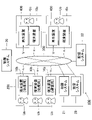
- FIG. 1 is a block diagram illustrating the configuration of the effect control system 100 according to the first embodiment.
- the effect control system 100 is a computer system for controlling visual effects at an event held in the venue 200.
- various events such as a competition event in which one or more competitors participate, or a music event in which one or more performers play or sing music are held in the venue 200.
- the venue 200 where the competition event is held is, for example, a stadium or a gymnasium.
- the venue 200 where the music event is held is, for example, an acoustic hall, a live house or an outdoor stage.
- the operator Ua and a plurality of visitors Ub are located in the venue 200.
- the operator Ua is an operator who operates a service using the effect control system 100. Specifically, the operator Ua manages the addition of visual effects using the effect control system 100.
- the operator Ua uses the terminal device 10a.
- Each of the plurality of visitors Ub will see the event held in the venue 200.
- Each visitor Ub uses the terminal device 10b.
- the terminal device 10b is used for directing an event in the venue 200.
- the terminal device 10a and the terminal device 10b are information devices such as a mobile phone, a smartphone, a tablet terminal, or a personal computer.
- Each viewer Uc is located, for example, at a point (for example, home) remote from the venue 200.
- Each viewer Uc uses the reproduction device 400 and the terminal device 10c.
- the terminal device 10c is an information device such as a mobile phone, a smartphone, a tablet terminal, or a personal computer. Each viewer Uc may be located in the venue 200.
- the playback device 400 plays the video content V.
- the video content V is content representing the status of an event held in the venue 200.
- the moving image content V is composed of video data representing video and acoustic data representing sound.
- the reproduction device 400 includes a display device for displaying the image represented by the video data and a sound emitting device for reproducing the sound represented by the acoustic data (not shown).
- a television receiver that reproduces a television program transmitted by broadcast radio waves as moving image content V is used as the reproduction device 400.
- an information device such as a smartphone or a tablet terminal is also used as the playback device 400.
- a large-scale video device (public viewing) that can be viewed by a large number of viewers Uc may be used as the playback device 400.
- the moving image content V may be audio content (for example, a radio program) composed of only acoustic data. Further, it is assumed that the terminal device 10c reproduces the moving image content V. That is, the reproduction device 400 is not indispensable for viewing the moving image content V.
- the effect control system 100 includes a recording system 21, a distribution system 22, and a control system 30.
- the control system 30 is a computer system for controlling the production in the venue 200.
- the recording system 21 records a video of an event held in the venue 200.
- the recording system 21 includes an imaging device that captures an image of an event and a sound collecting device that collects the sound of the event (not shown).
- the recording system 21 generates a moving image composed of an image captured by the image pickup device and a sound picked up by the sound pickup device.
- the distribution system 22 distributes the video content V including the video recorded by the recording system 21 to each of the plurality of playback devices 400.
- the distribution system 22 distributes (that is, live distribution) the video content V in real time in parallel with the progress of the event in the venue 200.
- Each reproduction device 400 receives the moving image content V distributed by the distribution system 22, and reproduces the moving image content V in parallel with the progress of the event.
- the viewer Uc can grasp the situation of the event in real time by viewing the moving image content V reproduced by the reproduction device 400.
- FIG. 2 is a block diagram illustrating the configuration of the terminal device 10 (10a, 10b, 10c).
- the terminal device 10 includes a control device 11, a storage device 12, a communication device 13, an operation device 14, and a display device 15.
- the terminal device 10 is realized not only as a single device but also as a plurality of devices configured as separate bodies from each other.
- the terminal device 10a used by the operator Ua includes a control device 11a, a storage device 12a, a communication device 13a, an operation device 14a, and a display device 15a.
- the terminal device 10b used by the visitor Ub includes a control device 11b, a storage device 12b, a communication device 13b, an operation device 14b, and a display device 15b.
- the terminal device 10c used by the viewer Uc includes a control device 11c, a storage device 12c, a communication device 13c, an operation device 14c, and a display device 15c.
- the control device 11 (11a, 11b, 11c) is composed of a single or a plurality of processors that control each element of the terminal device 10.
- the control device 11 is one or more types such as a CPU (Central Processing Unit), an SPU (Sound Processing Unit), a DSP (Digital Signal Processor), an FPGA (Field Programmable Gate Array), or an ASIC (Application Specific Integrated Circuit). It consists of a processor.
- the storage device 12 (12a, 12b, 12c) is a single or a plurality of memories for storing a program executed by the control device 11 and various data used by the control device 11.
- the storage device 12 is composed of a known recording medium such as a magnetic recording medium or a semiconductor recording medium.
- the storage device 12 may be configured by combining a plurality of types of recording media.
- the communication device 13 (13a, 13b, 13c) communicates with the control system 30 via a communication network 300 such as the Internet.
- the operation device 14 (14a, 14b, 14c) is an input device that receives instructions from the user U (operator Ua, visitor Ub, viewer Uc).
- the operation device 14 is, for example, a touch panel for detecting a plurality of operators operated by the user U or a contact by the user U.
- the display device 15 (15a, 15b, 15c) displays an image instructed by the control device 11.
- the display device 15 is, for example, a liquid crystal display panel or an organic EL display panel.
- FIG. 3 is a block diagram illustrating the configuration of the control system 30.
- the control system 30 includes a control device 31, a storage device 32, and a communication device 33.
- the control system 30 is realized not only as a single device but also as a set of a plurality of devices configured as separate bodies from each other.
- the control device 31 is composed of a single or a plurality of processors that control each element of the control system 30.
- the control device 31 is composed of one or more types of processors such as a CPU, SPU, DSP, FPGA, or ASIC.
- the storage device 32 is a single or a plurality of memories for storing a program executed by the control device 31 and various data used by the control device 31.
- the storage device 32 is composed of a known recording medium such as a magnetic recording medium or a semiconductor recording medium.
- the storage device 32 may be configured by combining a plurality of types of recording media.
- the communication device 33 communicates with each of the plurality of terminal devices 10 (10a, 10b, 10c) via the communication network 300.
- FIG. 4 is an explanatory diagram of the schematic operation of the effect control system 100.
- Each of the plurality of viewers Uc gives a predetermined operation (hereinafter referred to as “instruction operation”) to the operation device 14c of the terminal device 10c while viewing the moving image content V reproduced by the reproduction device 400.
- the instruction operation is, for example, a tap operation in contact with the display surface of the display device 15c.
- the communication device 13c of the terminal device 10c transmits a notification (hereinafter referred to as “operation notification”) A regarding the instruction operation to the control system 30.
- the operation notification A is transmitted for each instruction operation. That is, in parallel with the progress of the event in the venue 200, the operation notification A is transmitted in parallel or sequentially from each of the plurality of terminal devices 10c to the control system 30.
- the control system 30 receives the operation notification A transmitted from the plurality of terminal devices 10.
- each of the plurality of visitors Ub views the event with the display device 15b of the terminal device 10b pointed at the place where the event is developed in the venue 200.
- each visitor Ub maintains a state in which the display surface of the display device 15b faces the competition field where the competition event is developed or the stage where the music event is developed.
- the display device 15b of each terminal device 10b displays a predetermined image (hereinafter referred to as “effect image”) 62.
- the effect image 62 of the first embodiment is an image that occupies most of the display surface of the display device 15b, and the display color is uniform over the entire image.
- each display device 15b By displaying (that is, emitting light) the effect image 62 by each display device 15b, for example, a visual effect similar to an effect in which a large number of spectators in the venue 200 emit a penlight is realized.
- the terminal device 10a is a device for the operator Ua to instruct the start of the effect described above.
- the control system 30 controls the display color of the effect image 62 on the plurality of terminal devices 10b.
- the control system 30 of the first embodiment displays the effect image 62 in each of the plurality of terminal devices 10b from the initial display color (hereinafter referred to as “initial color”) C0 to a specific display color (hereinafter referred to as “target color”). Change to Ct.
- the initial color C0 of the effect image 62 is individually set for each terminal device 10b. Therefore, the initial color C0 of the effect image 62 is different between the two or more terminal devices 10b in the venue 200.
- the target color Ct is common among the plurality of terminal devices 10b.
- the number or ratio (hereinafter referred to as “effect progress”) of the terminal device 10b in which the effect image 62 changes from the initial color C0 to the target color Ct among the plurality of terminal devices 10b is set as the venue. Increase over time in parallel with the progression of events within 200. That is, the display color of the effect image 62 in each terminal device 10b sequentially changes from the initial color C0 individually set for each terminal device 10b to the common target color Ct. That is, the display colors of the plurality of effect images 62 are unified over time from the plurality of different initial colors C0 to the common target color Ct.
- the terminal device 10b functions as an effect imparting device for controlling a visual effect (effect) in the venue 200.
- the control system 30 of the first embodiment controls the display color of the effect image 62 in each terminal device 10b according to the number of times (hereinafter referred to as “reception number”) N of the operation notification A is received from the plurality of terminal devices 10c. Specifically, the degree of progress of the effect increases with time according to the number of times N of the operation notification A is received. That is, the control system 30 controls the rate of increase in the progress of the effect (for example, the amount of increase per unit time) according to the number of receptions N. For example, the control system 30 controls the display color of the effect image 62 on the terminal device 10b so that the increasing speed of the effect progress increases as the number of times N of the operation notification A is received increases.
- the time required for the light effect operation changes according to the number of receptions N. For example, when the number of receptions N is large, the display color of all the effect images 62 changes to the target color Ct in a short time, and when the number of receptions N is small, the display color of all the effect images 62 is long. To change to the target color Ct.
- each terminal device 10c is used for the viewer Uc to participate in the light staging operation. The specific operation for realizing the light effect operation will be described below.
- Each operation (Sa-Sd) illustrated below is executed in parallel with the progress of the event in the venue 200.
- FIG. 5 is a flowchart illustrating a specific procedure of a process (hereinafter referred to as “management process”) Sa executed by the control device 11a of the terminal device 10a used by the operator Ua.
- the management process Sa is started with the instruction from the operator Ua to the operating device 14a.
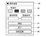
- the control device 11a of the terminal device 10a displays the operation screen 40 of FIG. 6 on the display device 15a (Sa1).
- the operation screen 40 is an image for the operator Ua to specify the conditions for the light effect operation.
- the operation screen 40 includes an operation image 41 (start), an operation image 42 (end), an operation image 43 (color selection), and an operation image 44.
- the operation image 41 is an image for the operator Ua to instruct the start of the light effect operation.
- the operation image 42 is an image for the operator Ua to instruct the end of the light effect operation.
- the operation image 43 is an image for the operator Ua to specify the target color Ct. That is, the operator Ua selects a desired target color Ct by operating the operation image 43 using the operation device 14a. For example, a color that symbolizes an athlete participating in a competition event or a performer in a music event is designated as the target color Ct. In FIG. 6, it is assumed that the operator Ua selects one of a plurality of colors prepared in advance.
- the method by which the operator Ua specifies the target color Ct is not limited to the above examples. For example, the operator Ua may specify the target color Ct by inputting the component values of red (R), green (G), and blue (B).
- the operation image 44 is an image for the operator Ua to instruct the shortest time T1 and the longest time T2.
- the time required for the light effect operation changes according to the number of receptions N.
- the shortest time T1 corresponds to the minimum value of the time required for the light effect operation, and is an example of the "first time”.
- the longest time T2 corresponds to the maximum value of the time required for the light effect operation, and is an example of the "second time”.
- the time required for the light effect operation is the time length from when the effect image 62 of the initial color C0 is displayed on each terminal device 10b until the effect image 62 of all the terminal devices 10b changes to the target color Ct. ..
- the control device 11a receives the selection of the target color Ct and the instruction of the shortest time T1 and the longest time T2 from the operator Ua (Sa2). Further, the control device 11a determines whether or not the operation of the operation image 41 by the operator Ua has been accepted (Sa3). That is, it is determined whether or not the operator Ua has instructed the start of the light effect operation. When the operation image 41 is not operated (Sa3: NO), the control device 11a continues to accept the instruction from the operator Ua (Sa2).
- the control device 11a transmits the start instruction Q1a from the communication device 13a to the control system 30 (Sa4).
- the start instruction Q1a is a message instructing the start of the light effect operation, and includes the target color Ct specified by the operator Ua and the shortest time T1 and the longest time T2 specified by the operator Ua.
- the control device 11a waits until the operator Ua operates the operation image 42 (Sa5: NO). That is, it is determined whether or not the operator Ua has instructed the end of the light effect operation.
- the control device 11a transmits the end instruction Q2a from the communication device 13a to the control system 30 (Sa6).
- the end instruction Q2a is a message instructing the end of the light effect operation.
- the operation of the terminal device 10a is as described above. As understood from the above description, the terminal device 10a is used as an operating device for operating the light staging operation. A device separate from the terminal device 10 may be dedicated for the operation of the light staging operation.
- FIG. 7 is a flowchart illustrating a specific procedure of a process (hereinafter referred to as “control process”) Sd executed by the control device 31 of the control system 30.
- the control device 31 waits for the reception of the start instruction Q1a transmitted from the terminal device 10a for operation (Sd1: NO).
- the control device 31 stores the target color Ct, the shortest time T1 and the longest time T2 included in the start instruction Q1a in the storage device 32 (Sd2). ..
- the control device 31 transmits a start instruction Q1b to each terminal device 10b and each terminal device 10c (Sd3).
- the start instruction Q1b is a message instructing the start of the light effect operation, and includes the target color Ct selected by the operator Ua.
- the terminal device 10b and the terminal device 10c to which the start instruction Q1b is transmitted are registered in advance in the storage device 32.
- the control device 31 initializes the control value X to the minimum value xL (Sd4).
- the control value X is a variable for controlling the progress of the effect, and increases with time at a speed corresponding to the number of times N of the operation notification A is received.
- the minimum value xL of the control value X is, for example, 0.
- the control device 31 starts measuring the elapsed time t of the light effect operation (Sd5).
- the elapsed time t is the length of time elapsed from the start of the light staging operation.
- the control device 31 receives the operation notification A transmitted from each of the plurality of terminal devices 10c by the communication device 33 (Sd6). That is, the control device 31 functions as a receiving unit that receives the operation notification A transmitted from each of the plurality of terminal devices 10c in response to the instruction operation by the viewer Uc.
- the control device 31 totals the number of times N of the operation notification A is received (Sd7). Specifically, the number of times the operation notification A is received within a unit period of a predetermined length is totaled as the number of times N is received.
- the control device 31 updates the control value X according to the number of receptions N (Sd8).
- FIG. 8 is an explanatory diagram regarding the temporal change of the control value X.
- the control device 31 updates the control value X so that the control value X increases at a speed corresponding to the number of receptions N.
- the control value X is updated so that the rate of increase of the control value X increases as the number of receptions N increases.
- the increasing speed of the control value X is updated every time the total number of receptions N is totaled (Sd7). Therefore, as shown by the chain line in FIG. 8, the control value X changes in a polygonal line with the passage of time t from the minimum value xL, and finally reaches a predetermined maximum value xH.
- the maximum value xH is set to, for example, 100.
- the upper limit value EH (t) in FIG. 8 is a numerical value that changes over time over the shortest time T1 instructed by the operator Ua. Specifically, the upper limit value EH (t) linearly increases from the minimum value xL to the maximum value xH over the shortest time T1.
- the lower limit value EL (t) is a numerical value that changes with time over the longest time T2, which is longer than the shortest time T1. Specifically, the lower limit value EL (t) linearly increases from the minimum value xL to the maximum value xH over the longest time T2. Therefore, the lower limit value EL (t) is lower than the upper limit value EH (t).
- FIG. 8 The upper limit value EH (t) in FIG.
- the upper limit value EH (t) changes linearly with the passage of time t is illustrated, but the relationship between the time t and the upper limit value EH (t) is limited to the above example. Not done.
- the upper limit value EH (t) may change in a curved or polygonal shape with respect to the time t.
- the relationship between the time t and the lower limit value EL (t) is not limited to the linear relationship shown in FIG.
- the lower limit value EL (t) may change in a curved or polygonal shape with respect to the time t.
- the minimum value xL is an example of the "first value”
- the maximum value xH is an example of the "second value”.
- the control device 31 changes the control value X within the range between the upper limit value EH (t) and the lower limit value EL (t) at the current time t. That is, if the control value X exceeds the upper limit value EH (t) when the control value X is increased at an increase rate corresponding to the number of receptions N, the control value X is set to the upper limit value EH (t). .. On the other hand, if the control value X is lower than the lower limit value EL (t) when the increase rate is increased according to the number of receptions N, the control value X is set to the lower limit value EL (t). As understood from the above description, the time required for the control value X to change from the minimum value xL to the maximum value xH is within the range of the shortest time T1 or more and the longest time T2 or less.
- the control device 31 determines whether or not the communication device 33 has received the information request R from the terminal device 10b or the terminal device 10c (Sd9).
- the information request R is a message requesting the control system 30 for the control value X.
- the control device 31 transmits the control value X after the latest update (Sd8) from the communication device 33 to the requesting terminal device 10b or the terminal device 10c. (Sd10).
- the information request R is not received (Sd9: NO)
- the transmission of the control value X (Sd10) is not executed.
- the control device 31 determines whether or not the communication device 33 has received the end instruction Q2a from the terminal device 10a of the operator Ua (Sd11). When the end instruction Q2a is not received (Sd11: NO), the control device 31 shifts the process to step Sd6. That is, the reception and aggregation of the operation notification A (Sd6, Sd7), the update of the control value X (Sd8), and the transmission of the control value X to the terminal device 10b (Sd9, Sd10) are repeated until the end instruction Q2a is received. Will be done.
- the control device 31 transmits the end instruction Q2b to each terminal device 10b and each terminal device 10c (Sd12).
- the control process Sd is terminated by the transmission of the termination instruction Q2b.
- FIG. 9 is a flowchart illustrating a specific procedure of a process (hereinafter referred to as “participation process”) Sc executed by the control device 11c of the terminal device 10c used by the viewer Uc.
- the participation process Sc is a process for the viewer Uc to be involved in the light staging operation in the venue 200. Participation processing Sc is started triggered by an instruction from the viewer Uc to the operating device 14c.
- the control device 11c waits for the reception of the start instruction Q1b transmitted from the control system 30 (Sc1: NO).
- the control device 11c stores the target color Ct included in the start instruction Q1b in the storage device 12c (Sc2).
- the control device 11c displays the operation image 51 on the display device 15c as illustrated in FIG. 10 (Sc3).
- the operation image 51 is an image for the viewer Uc to instruct to participate in the light effect operation.
- the control device 11c waits until the viewer Uc operates the operation image 51 (Sc4: NO). As described above, each viewer Uc is in a state of being able to participate in the light staging operation triggered by the operation of the operation image 41 by the operator Ua.
- the control device 11c causes the display device 15c to display the initial situation image 52 as illustrated in FIG. 10 (Sc5).
- the situation image 52 is an image showing the progress of the light effect operation. Specifically, the situation image 52 includes an effective region 53 displayed in the target color Ct. In the initial stage immediately after the participation process Sc is started, the effective domain 53 is displayed in a small area.
- the viewer Uc executes an instruction operation (for example, a tap operation) while visually recognizing the situation image 52.
- the control device 11c determines whether or not the operation device 14c has accepted the instruction operation by the viewer Uc (Sc6).
- the control device 11c transmits an operation notification A indicating acceptance of the instruction operation from the communication device 13c to the control system 30 (Sc7).
- the control system 30 receives the operation notification A transmitted from each terminal device 10c (Sd6).
- the control device 11c does not execute the transmission of the operation notification A (Sc7).
- the operation notification A is transmitted to the control system 30 for each instruction operation by the viewer Uc.
- the control device 11c repeats the transmission (Sc6, Sc7) of the operation notification A until a predetermined time elapses from the display or update of the status image 52 (Sc8: NO).
- the control device 11c transmits the information request R from the communication device 13c to the control system 30 (Sc9).
- the control system 30 that has received the information request R from the terminal device 10c (Sd9: YES) transmits the current control value X to the terminal device 10c (Sd10).
- the control device 11c of the terminal device 10c receives the control value X transmitted from the control system 30 by the communication device 13c (Sc10). That is, the control device 11c functions as a receiving unit that receives the control value X from the control system 30.
- the control device 11c updates the status image 52 according to the current control value X received from the control system 30 (Sc11). Specifically, as illustrated in FIG. 10, the control device 11c expands the area of the effective region 53 displayed in the situation image 52 in the target color Ct according to the control value X. The area of the effective region 53 expands over time as the control value X increases. Further, when the control value X reaches a predetermined maximum value xH, the control device 11c causes the display device 15c to display the predetermined achievement image 54 as illustrated in FIG.
- the achievement image 54 is an image meaning that the effect progress has reached the maximum value.
- the control device 11c determines whether or not the communication device 13c has received the end instruction Q2b from the control system 30 (Sc12).
- the control device 11c shifts the process to step Sc6. That is, the transmission of the operation notification A (Sc6, Sc7) for each instruction operation by the viewer Uc and the update of the situation image 52 (Sc8 to Sc11) according to the control value X are repeated until the end instruction Q2b is received. ..
- the participation process Sc ends when the end instruction Q2b is received (Sc12: YES).
- FIG. 11 is a flowchart illustrating a specific procedure of a process (hereinafter referred to as “staging process”) Sb executed by the control device 11b of the terminal device 10b used by the visitor Ub in the venue 200.
- the staging process Sb is started triggered by an instruction from the visitor Ub to the operating device 14b. It is also assumed that the user U (visitor Ub or viewer Uc) can select which of the participation process Sc and the effect process Sb is to be executed by the terminal device 10.
- the participation process Sc is selected, the terminal device 10 is used as the terminal device 10c for the viewer Uc, and when the effect process Sb is selected, the terminal device 10 is used as the terminal device 10b for the visitor Ub. .. That is, the user U can select whether to use the terminal device 10 as the terminal device 10b for staging or as the terminal device 10c for viewing.
- the control device 11b waits for the reception of the start instruction Q1b transmitted from the control system 30 (Sb1: NO).
- the control device 11b stores the target color Ct included in the start instruction Q1b in the storage device 12b (Sb2).
- the control device 11b displays the operation image 61 on the display device 15b as illustrated in FIG. 12 (Sb3).
- the operation image 61 is an image for the visitor Ub to instruct to participate in the light effect operation.
- the control device 11b waits until the viewer Uc operates the operation image 61 (Sb4: NO). As described above, each visitor Ub is in a state of being able to participate in the light staging operation triggered by the operation of the operation image 41 by the operator Ua.
- the control device 11b sets the initial color C0 (Sb5). For example, the control device 11b randomly selects any of a plurality of colors as the initial color C0. Specifically, the control device 11b generates, for example, a random number having a uniform distribution, and sets the color corresponding to the random number among the plurality of colors as the initial color C0. As illustrated in FIG. 12, the control device 11b causes the display device 15b to display the effect image 62 of the initial color C0 (Sb6). As described above, since the initial color C0 is individually set for each terminal device 10b, as illustrated in FIG. 4, the initial color C0 is different between the two or more terminal devices 10b in the venue 200.
- control device 11b sets the set value Y (Sb7).
- the set value Y is set to a numerical value (xL ⁇ Y ⁇ xH) within the range from the minimum value xL to the maximum value xH of the control value X.
- the control device 11b randomly selects a numerical value in the range from the minimum value xL to the maximum value xH as the set value Y.
- the control device 11b sets, for example, a random number generated by a uniform distribution within the range from the minimum value xL to the maximum value xH as the set value Y.
- the set value Y is different between two or more terminal devices 10 in the venue 200.
- the control device 11b waits until a predetermined time elapses (Sb8). When the predetermined time has elapsed (Sb8: YES), the control device 11b transmits the information request R from the communication device 13b to the control system 30 (Sb9). As described above, the control system 30 that has received the information request R from the terminal device 10b (Sd9: YES) transmits the current control value X to the terminal device 10b (Sd10). The control device 11b of the terminal device 10b receives the control value X transmitted from the control system 30 by the communication device 13b (Sb10).
- the control device 11b determines whether or not the current control value X received from the control system 30 exceeds the set value Y (Sb11). When the control value X is less than the set value Y (Sb11: NO), the control device 11b shifts the process to step Sb8. That is, the acquisition of the latest control value X (Sb9, Sb10) and the comparison between the control value X and the set value Y (Sb11) are repeated at predetermined time intervals.
- the control device 11b stores the display color of the effect image 62 displayed on the display device 15b in the storage device 12b as illustrated in FIG. Change to the target color Ct (Sb12). That is, when the control value X, which increases with time, reaches the set value Y, the display color of the effect image 62 changes from the initial color C0 to the target color Ct.
- the operation (Sd10) in which the control device 31 of the control system 30 transmits the control value X to each terminal device 10b causes the display colors in the plurality of terminal devices 10b in the venue 200 to be received the number of times.
- a control unit that controls according to N is realized.
- control device 11b of the terminal device 10b functions as a control unit that changes the display mode of the display device 15b.
- the control value X and the set value Y are equal to each other, either the transition to step Sb8 or the update of the effect image 62 (Sb12) may be executed.
- the set value Y is individually set for each terminal device 10b.
- the control value X is common to the plurality of terminal devices 10b. Therefore, the time point at which the display color of the effect image 62 changes from the initial color C0 to the target color Ct differs for each terminal device 10b. That is, the ratio of the terminal device 10b in which the display color of the effect image 62 changes to the target color Ct (that is, the degree of effect progress) among the plurality of terminal devices 10b in the venue 200 increases with time as the control value X increases. Finally, the effect image 62 of all the terminal devices 10b changes to the target color Ct.
- the rate of increase of the control value X is controlled according to the number of receptions N of the operation notification A, the progress of the effect also increases with time at a rate corresponding to the number of receptions N.
- the time point at which the display color of the effect image 62 in each terminal device 10b changes from the initial color C0 to the target color Ct is controlled according to the number of times N of the operation notification A is received.
- the number or ratio of the terminal devices 10b corresponding to the control value X among the plurality of terminal devices 10b in the venue 200 displays the target color Ct. That is, the control value X is substantially equated with the degree of effect progress.
- the control value X is a range between the upper limit value EH (t) that changes over time over the shortest time T1 and the lower limit value EL (t) that changes over time over the longest time T2. Changes over time within. Therefore, the degree of effect progress changes over time between the maximum value that changes over time over the shortest time T1 and the minimum value that changes over time over the longest time T2.
- the time until the display color of the effect image 62 in all the terminal devices 10b changes to the target color Ct is limited to the range of the shortest time T1 or more and the longest time T2 or less. Therefore, the maximum time T2 is set until all the effect images 62 change to the target color Ct or the display colors of all the effect images 62 change to the target color Ct in an excessively short time less than the shortest time T1. It is possible to prevent the passage of an excessively long time exceeding that.
- the display color of the effect image 62 in the plurality of terminal devices 10b in the venue 200 is changed according to the number of times N of the operation notifications A transmitted from the plurality of terminal devices 10c are received. Be controlled. Therefore, the viewer Uc located outside the venue 200 can be involved in the visual effect inside the venue 200.
- the display color of the effect image 62 in the plurality of terminal devices 10b in the venue 200 changes to the common target color Ct, an effective effect with a visual sense of unity or a sense of unity is realized. can.
- Each viewer Uc can also confirm how the light staging operation progresses in the venue 200 by viewing the video content V recording the state in the venue 200.
- the effect progress degree which is the number or ratio of the terminal devices 10b in which the display color of the effect image 62 has changed to the target color Ct among the plurality of terminal devices 10b, increases with time according to the number of receptions N. do. Therefore, a plurality of viewers Uc outside the venue 200 can be involved in the rate of increase in the degree of effect progress within the venue 200.
- the terminal device 10b when the control value X acquired from the control system 30 by each of the plurality of terminal devices 10b reaches the set value Y set for each terminal device 10b, the terminal device 10b is used.
- the display color of the effect image 62 changes to the target color Ct. Therefore, there is an advantage that the control system 30 does not need to manage the display color of the effect image 62 in each of the plurality of terminal devices 10b.
- FIG. 13 is a block diagram illustrating the configuration of the effect control system 100 according to the second embodiment.
- the effect control system 100 of the second embodiment includes a sound emitting system 25 in addition to the same elements as those of the first embodiment.
- the sound emitting system 25 is an acoustic system composed of acoustic equipment installed in the venue 200, and emits sound in the venue 200.
- the sound emitting system 25 includes, for example, a plurality of sound emitting devices installed at different locations in the venue 200.
- the control system 30 of the second embodiment controls the light effect operation as in the first embodiment, and causes the sound emitting system 25 to emit various sound effects.
- Sound effects are sound effects for directing an event. For example, singing and musical instrument sounds of cheering songs related to participants in competition events, cheers uttered by a large number of spectators, clapping sounds generated by the clapping of spectators, sighing sounds produced by a large number of spectators when discouraged, etc. are used as effect sounds. Illustrated.
- the control system 30 selectively causes the sound emitting system 25 to emit any one of the plurality of sound effects.
- the control system 30 transmits any one of a plurality of acoustic data representing different waveforms of sound effects to the sound emitting system 25, the sound emitting system 25 emits a sound effect corresponding to the acoustic data. ..
- the control system 30 may be composed of a device for controlling the light effect operation and a device for controlling the sound emission of the sound effect.
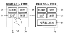
- FIG. 14 is a schematic diagram of a selection screen 70 displayed by the display device 15c of the terminal device 10c used by the viewer Uc.
- the selection screen 70 is an image for the viewer Uc to select any one of a plurality of types of sound effects. Specifically, a plurality of operation images 71 corresponding to different sound effects are arranged on the selection screen 70. Each operation image 71 is a software button that can be operated by the viewer Uc using the operation device 14c.
- the “cheering song” in FIG. 14 means the singing sound and the musical instrument sound of the cheering song relating to the participants of the competition event.
- “Cheers” means the cheers uttered by the spectators at a competition event.
- “Applause” means the applause sound produced by the applause of the audience.
- “Disappointment” means the sighing sound that the audience makes when they are discouraged.
- the viewer Uc can select any of a plurality of types of sound effects from the selection screen 70 by operating the operation device 14c while watching the video content V.
- the control device 11c of the terminal device 10c transmits a selection notification B for designating the sound effect selected by the viewer Uc from the communication device 13c to the control system 30.
- the control device 11c displays the operation image 51 on the display device 15c so as to overlap the selection screen 70 as illustrated in FIG. Let (Sc3).
- the plurality of operation images 71 are displayed on the display device 15c, but the operation image 51 is not displayed. That is, the state of accepting the selection of the sound effect by the viewer Uc shifts to the state of accepting the selection of the sound effect and the instruction to participate in the light effect operation, triggered by the reception of the start instruction Q1b.
- FIG. 15 is a flowchart illustrating a specific procedure of a process (hereinafter referred to as “sound effect processing”) Se for the control system 30 of the second embodiment to control the sound emission of the sound effect.
- the control device 31 of the control system 30 executes the sound emission processing Se in parallel with the control processing Sd (FIG. 7) similar to that of the first embodiment. That is, the sound emission processing Se is executed in parallel with the progress of the event in the venue 200. The sound emission processing Se is repeated at a predetermined cycle.
- the control device 31 receives the selection notification B transmitted from each terminal device 10c by the communication device 33 (Se1).
- the control device 31 calculates the number of selections M for each of the plurality of types of sound effects by aggregating the sound effects designated by each selection notification B (Se2).
- the number of times each sound effect is selected M is the number of times the sound effect is selected by a plurality of viewers Uc.
- the control device 31 selects one of a plurality of types of sound effects according to the number of times M of each sound effect is selected (Se3). For example, the control device 31 selects a sound effect (hereinafter referred to as “selection sound effect”) having the maximum number of selections M among a plurality of types of sound effects.
- the control device 31 causes the sound emitting system 25 to emit the selected sound effect (Se4).
- the control device 31 supplies the acoustic data of the selected sound effect to the sound emitting system 25 to emit the selected sound effect.
- the control device 31 may adjust the volume of the selected sound effect by processing the acoustic data according to the number of times M of the selected sound effect is selected. For example, it is assumed that the volume of the selection sound effect increases as the number of selections M increases.
- both the visual effect and the auditory effect can be realized in the venue 200. Further, a plurality of viewers Uc can be involved in both the visual effect and the auditory effect.
- FIG. 16 is a schematic diagram of an operation screen 40 displayed on the display device 15a of the terminal device 10a in the third embodiment.
- the operation screen 40 of the third embodiment includes an operation image 46 (immediate change) in addition to the same elements as the operation screen 40 of the first embodiment illustrated in FIG.
- the light effect operation gradually progresses over a time within the range of the shortest time T1 or more and the longest time T2 or less.
- the operation image 46 of FIG. 16 is an image for the operator Ua to immediately and forcibly terminate the light effect operation.
- the control device 11a of the terminal device 10a transmits an immediate termination instruction from the communication device 13a to the control system 30.
- FIG. 17 is a flowchart illustrating a part of the control process Sd in the third embodiment.
- the control device 31 determines whether or not the communication device 33 has received the immediate termination instruction from the terminal device 10a (Sd21).
- the control device 31 sets the control value X to the maximum value xH (Sd22).
- the process of setting the control value X to the maximum value xH is not executed.
- the control device 31 transmits the control value X to the terminal device 10b or the terminal device 10c as in the first embodiment (Sd9, Sd10).
- control value X When the control value X is set to the maximum value xH, the control value X naturally exceeds the set value Y set for each terminal device 10b (Sb11). That is, the result of the determination in step Sb11 in the effect processing Sb (FIG. 11) is affirmative (Sb11: YES). Therefore, in all the terminal devices 10b in which the effect image 62 is not changed to the target color Ct, the display color of the effect image 62 is changed to the target color Ct. That is, the light effect operation forcibly proceeds to the final state. Further, by setting the control value X to the maximum value xH, the achievement image 54 is displayed on the terminal device 10c.
- the operator Ua can immediately and forcibly terminate the light staging operation.
- the configuration of the second embodiment in which the sound emitting system 25 emits a sound effect may be applied to the third embodiment.
- the light effect operation is terminated by setting the control value X to the maximum value xH, but the control device 31 of the control system 30 outputs the instruction data instructing the end of the light effect operation to each terminal. It may be transmitted to the device 10b and each terminal device 10c.
- the control device 11b of the terminal device 10b receives the instruction data from the control system 30, the control device 11b changes the display color of the effect image 62 to the target color Ct.
- the control device 11c of the terminal device 10c receives the instruction data from the control system 30, the control device 11c causes the display device 15c to display the achievement image 54.
- a form in which the display color by the display device 15b is changed to the target color Ct is exemplified, but the display mode changed according to the number of times N of the operation notification A is received is not limited to the display color. .. That is, the type of display mode is arbitrary as long as the display mode is controlled according to the number of receptions N.
- the "display mode” means a characteristic of the display that can be visually discriminated by the observer. For example, in addition to the display colors exemplified in each of the above-described forms, the pattern (design) or shape of the effect image 62 is included in the concept of "display mode".
- the "display color” is defined by hue (hue), saturation or lightness (gradation).
- One or more of the display modes exemplified above are controlled according to the number of times N of the operation notification A is received.
- the process of changing the display color of the effect image 62 from the initial color C0 to the target color Ct is a process of changing the display mode of the terminal device 10b from the initial display mode (initial mode) to the target display mode (target mode). Expressed comprehensively. In each of the above-mentioned forms, a form in which the entire display color of the effect image 62 changes is illustrated, but a form in which a part of the display mode of the effect image 62 changes is also assumed.
- the terminal device 10b used by the visitor Ub is exemplified as an effect-imparting device (hereinafter referred to as "effect-imparting device"), but the effect-imparting device is not limited to the above examples.
- a lighting device having a variable emission color may be used as an effect imparting device.
- the illuminating device comprises a portable (eg, penlight type) illuminant capable of communicating with the control system 30.
- the emission color of the lighting device changes from the initial color C0 to the target color Ct by the same operation as the terminal device 10b in each of the above-described embodiments.
- a display device installed in the venue 200 may be used as an effect imparting device.
- the display device is a large display body (for example, a back screen installed in a baseball field) capable of communicating with the control system 30.
- the display color of the display device changes from the initial color C0 to the target color Ct by the same operation as the terminal device 10b in each of the above-described embodiments.
- the effect imparting device is an arbitrary device whose display mode can be changed. In the configuration in which the lighting device is used as the effect imparting device, the emission color or the emission amount is included in the concept of "display mode".
- the tap operation on the display surface of the display device 15c is exemplified as an instruction operation, but the instruction operation is not limited to the above examples.
- a flick operation or a double tap operation on the display surface of the display device 15c, or an operation of pressing an operator included in the operation device 14c is also included in the "instruction operation”.
- the instruction operation is not limited to the operation detected by the operation device 14c.
- the operation of the viewer Uc detected by a detection device (for example, an acceleration sensor) other than the operation device 14c is also included in the “instruction operation”.
- the detection device may detect the action of the viewer Uc shaking the terminal device 10c as an "instruction operation”.
- the display color of the effect image 62 is switched from the initial color C0 to the target color Ct, but the mode of change in the display color is not limited to the above examples.
- the display color of the effect image 62 may change stepwise or continuously from the initial color C0 to the target color Ct.
- a configuration is assumed in which the display color of the effect image 62 is multivaluedly controlled according to the control value X within the range between the initial color C0 and the target color Ct.
- the speed at which the display color of the effect image 62 changes from the initial color C0 to the target color Ct may be controlled according to the number of times N of the operation notification A is received.
- the display color of the effect image 62 in each terminal device 10b is changed from the initial color C0 to the target color Ct at the time corresponding to the reception count N of the operation notification A.
- the relationship with the display mode of the terminal device 10b is not limited to the above examples.
- the brightness or saturation of the effect image 62 in each terminal device 10b may be controlled according to the number of receptions N.
- the display mode of the effect image 62 in each terminal device 10b may be changed at a frequency corresponding to the number of receptions N.
- controlling the display mode according to the number of receptions N means that the display mode in the terminal device 10b changes in conjunction with the change in the number of receptions N. That is, it is assumed that the change in the display mode (for example, the condition of change) is different between the case where the number of receptions N is the first value and the case where the number of receptions N is a second value other than the first value. .. In other words, the time change of the effect progress when the number of receptions N is the first value and the time change of the effect progress when the number of receptions N is the second value are different.
- the rate of increase of the control value X (effect progress) is controlled according to the number of receptions N of the operation notification A, but the relationship between the number of receptions N and the control value X is illustrated above. Not limited. Specifically, a configuration is also assumed in which the control value X is increased at a frequency corresponding to the number of receptions N.
- the display color of the effect image 62 in each terminal device 10b is changed to a common target color Ct among the plurality of terminal devices 10b, but the final effect image 62 is illustrated. It is not essential that the display mode is common to the plurality of terminal devices 10b. For example, contrary to each of the above-described forms, the display color of the effect image 62 may change from the initial color C0 common to the plurality of terminal devices 10b to the target color Ct individually set for each terminal device 10b. is assumed.
- the control system 30 comprehensively sets the initial color for each of the plurality of terminal devices 10b.
- C0 may be set.
- the control device 31 of the control system 30 selects any of a plurality of display colors as the initial color C0 for each of the plurality of terminal devices 10b, and notifies each terminal device 10b of the initial color C0.
- the initial color C0 of the effect image 62 can be appropriately dispersed in the plurality of terminal devices 10b.
- the mode in which the set value Y is individually set by each terminal device 10b is illustrated, but the control system 30 collectively sets the set value Y for each of the plurality of terminal devices 10b. May be good.
- the control device 31 of the control system 30 sets different set values Y for each of the plurality of terminal devices 10b, and notifies each terminal device 10b of the set value Y.
- the control device 11b of each terminal device 10b receives the set value Y by the communication device 13b.
- the specific processing to which the set value Y is applied is the same as that in the first embodiment. According to the above configuration, the set value Y can be appropriately dispersed in the plurality of terminal devices 10b.
- the control device 11b of the terminal device 10b functions as an element (acquisition unit) for acquiring the set value Y.
- the acquisition unit includes both an element for setting the set value Y as in the example of the first embodiment and an element for receiving the set value Y from the control system 30.
- the effect image 62 is not limited to the images exemplified above.
- an arbitrary image such as an image having a different display color for each area or an image including various patterns such as a geometric pattern is used as the effect image 62.
- the terminal device 10b changes the display color of the effect image 62 from the initial color C0 to the target color Ct.
- the specific configuration and method for changing the display color of the effect image 62 in each terminal device 10b is not limited to the above examples.
- an instruction to change the display color of the effect image 62 from the initial color C0 to the target color Ct (hereinafter referred to as “change instruction”) may be transmitted from the control system 30 to each terminal device 10b.
- control device 31 of the control system 30 sequentially selects each of the plurality of terminal devices 10b so that the effect progress degree increases with time according to the number of receptions N, and each of the selected terminal devices 10b Send a change instruction to.
- Each terminal device 10b changes the display color of the effect image 62 from the initial color C0 to the target color Ct when the communication device 13b receives the change instruction from the control system 30.
- the user U selects whether to use the terminal device 10 as the terminal device 10b for staging or as the terminal device 10c for viewing, but the terminal located in the venue 200. It is also assumed that the device 10 is operated as the terminal device 10b for staging, and the terminal device 10 not located in the venue 200 is operated as the terminal device 10c for viewing.
- a wireless transmission device is installed in the venue 200.
- the wireless transmission device transmits confirmation data indicating that the terminal device 10 is located in the venue 200 into the venue 200 by short-range wireless communication. That is, the terminal device 10 located inside the venue 200 can receive the confirmation data, but the terminal device 10 located outside the venue 200 cannot receive the confirmation data.
- the terminal device 10 that has received the confirmation data operates as the terminal device 10b for the effect, and the terminal device 10 that cannot receive the confirmation data operates as the terminal device 10c for viewing.
- the short-range wireless communication executed by the wireless transmission device is, for example, wireless communication such as Bluetooth (registered trademark) or Wi-Fi (registered trademark), or acoustic communication using sound as a transmission medium.
- a sound emitting device that emits a guidance voice in the venue 200 is used as a wireless transmission device.
- the terminal device 10 that has executed the reading of the QR code (registered trademark) posted in the venue 200 may be operated as the terminal device 10b for staging.
- the functions of the control system 30 exemplified above are realized by the cooperation of the single or a plurality of processors constituting the control device 31 and the program stored in the storage device 32. Further, the functions of the terminal devices 10 (10a, 10b, 10c) are realized by the cooperation between the single or a plurality of processors constituting the control device 11 and the program stored in the storage device 12.
- the program exemplified above can be provided in a form stored in a computer-readable recording medium and installed in the computer.
- the recording medium is, for example, a non-transitory recording medium, and an optical recording medium (optical disc) such as a CD-ROM is a good example, but a semiconductor recording medium, a magnetic recording medium, or the like is known as arbitrary. Recording media in the form of are also included.
- the non-transient recording medium includes any recording medium other than the transient propagation signal (transitory, propagating signal), and the volatile recording medium is not excluded. Further, in the configuration in which the distribution device distributes the program via the communication network, the recording medium for storing the program in the distribution device corresponds to the above-mentioned non-transient recording medium.
- the effect control method receives an operation notification transmitted from each of a plurality of terminal devices in response to an operation by a user of the terminal device, and one or more effect imparting devices.
- the display mode of is controlled according to the number of times the operation notification is received.
- the display mode of the effect imparting device is controlled according to the number of times of receiving the operation notification transmitted from the plurality of terminal devices. Therefore, for example, a user of a terminal device located in a place other than a specific place can be involved in a visual effect in a specific place.
- the one or more effect-imparting devices are a plurality of effect-imparting devices, and in the control of the display mode, each display mode of the plurality of effect-imparting devices is common. Change to the target aspect of.
- the display mode of the plurality of effect-imparting devices changes to a common target mode. Therefore, it is possible to realize an effective production with a visual sense of unity or unity. It does not matter whether the display mode changes to the target mode in each of the plurality of effect-imparting devices.
- the effect progress degree is the number or ratio of the effect imparting devices whose display aspect is changed to the target aspect among the plurality of effect imparting devices.
- Each display mode of the plurality of effect-imparting devices is controlled so as to increase with time according to the number of receptions.
- the effect progress degree which is the number or ratio of the effect-imparting devices whose display mode has changed among the plurality of effect-imparting devices, increases with time according to the number of times the operation notification is received. Therefore, the user of the terminal device can be involved in the rate of increase in the progress of the effect at a specific place.
- the relationship between the number of times the operation notification is received and the progress of the effect is arbitrary. For example, it is assumed that the effect progress monotonically increases with the increase in the number of times the operation notification is received. It should be noted that the effect progress does not need to be linked to the number of receptions over the entire numerical range of the number of receptions. For example, it is assumed that the effect progress does not change with respect to the change in the number of receptions within a specific range.
- the display mode of each of the plurality of effect-imparting devices is set so that the rate of increase of the effect progress rate changes according to the number of receptions. Control.
- the speed at which the overall display aspect across the plurality of effect-imparting devices changes to the target aspect can be controlled. For example, it is assumed that the rate of increase in the progress of the effect increases as the number of times the operation notification is received increases.
- the rate of increase in the degree of effect progress means the rate of increase in the degree of effect progress over time (the amount of increase per unit time).
- the display mode of each of the plurality of effect-imparting devices is controlled so that the degree of progress of the effect changes within the range between the first value and the lower limit value increasing from the second value over two hours. do.
- the time until all the display modes of the plurality of effect-imparting devices change to the target mode can be limited to the range of the first time or more and the second time or less. That is, it is possible to change the display mode of the plurality of effect-imparting devices to the target mode over an appropriate time of 1st time or more and 2nd time or less.
- the display mode of all effect-imparting devices changes to the target mode in an excessively short time, or an excessively long time elapses before the display mode of all effect-imparting devices changes to the target mode. Can be suppressed.
- each of the plurality of effect-imparting devices sets a set value, and in the control of the display mode, the terminal is selected from each of the plurality of terminal devices.
- the control system that receives the operation notification of the device increases the control value over time according to the number of receptions, and each of the plurality of effect-imparting devices acquires the control value from the control system, and the effect is obtained.
- the display mode is changed to the target mode.
- the effect-imparting device changes the display mode. Therefore, it is not necessary for the control system to grasp the display mode in each of the plurality of effect-imparting devices.
- any specific example (aspect 8) of any one of aspects 1 to 7 the transmission of the operation notification by each of the plurality of terminal devices and the effect of the above 1 or more are triggered by the instruction from the operator who manages the effect addition. Control of the display mode of the granting device is started.
- the transmission of the operation notification by each terminal device and the control of the display mode of the effect imparting device are started by the instruction from the operator to the operating device. Therefore, it is possible to avoid a situation in which the display mode of the effect-imparting device changes at an inappropriate time.
- the display mode of each of the plurality of effect-imparting devices is set to the target mode, triggered by an instruction from the operator to the operating device. Change. According to the above aspects, the operator can immediately and forcibly terminate the operation of sequentially changing the display mode of each of the plurality of effect-imparting devices to the target mode.
- the selected sound effect in the sound emission of the sound effect, is emitted to the sound emitting system at a volume corresponding to the number of times the sound effect is selected.
- the user of the terminal device can be involved in the volume of the sound effect.
- the control system includes a receiving unit that receives an operation notification transmitted from each of a plurality of terminal devices in response to an operation by a user of the terminal device, and one or more effects. It includes a control unit that controls the display mode of the granting device according to the number of times the operation notification is received.
- the terminal device is an operation notification transmitted from each of the acquisition unit for acquiring a set value and each of the plurality of terminal devices in response to an operation by a user of the terminal device. It is provided with a receiving unit that receives a control value that increases with time according to the number of times of receiving the control value from the control system, and a control unit that changes the display mode of the display device when the control value reaches the set value. ..
- 100 Effect control system, 10 (10a, 10b, 10c) ... Terminal device, 11 (11a, 11b, 11c) ... Control device, 12 (12a, 12b, 12c) ... Storage device, 13 (13a, 13b, 13c) ... communication device, 14 (14a, 14b, 14c) ... operation device, 15 (15a, 15b, 15c) ... display device, 21 ... recording system, 22 ... distribution system, 30 ... control system, 31 ... control device, 32 ... Storage device, 33 ... Communication device.
Landscapes
- Engineering & Computer Science (AREA)
- Computer Networks & Wireless Communication (AREA)
- Circuit Arrangement For Electric Light Sources In General (AREA)
Abstract
効果制御システムは、複数の端末装置の各々から視聴者による操作に応じて送信される操作通知を受信し、1以上の端末装置の各々における演出画像の表示態様を、操作通知の受信回数に応じて制御する。
Description
本開示は、演出効果を制御する技術に関する。
競技イベントまたは音楽イベント等の各種のイベントが実施される場所(以下「実施場所」という)では、雰囲気を盛上げるために視覚的な演出効果が重要である。例えば特許文献1には、実施場所においてイベントを観覧する観覧者が所持するペンライトの発光を、制御装置から送信される制御データに応じて制御する技術が開示されている。また、特許文献2には、実施場所内の観覧者が所持する携帯端末の画面を、音声ビーコンにより送信される点滅パターンで発光させる技術が開示されている。
ところで、イベントの実施場所に実際に来場した観覧者が当該イベントを観覧するだけでなく、イベントを収録した動画コンテンツの配信により、実施場所以外の場所にいる視聴者が当該イベントをリアルタイムに視聴できる場合がある。しかし、実施場所以外の場所の視聴者は動画コンテンツを視聴できるだけであり、実施場所内の演出効果に関与することはできない。以上の事情を考慮して、本開示のひとつの態様は、イベントの実施場所以外の場所に所在する多数の利用者が実施場所における演出効果に関与できるようにすることを目的とする。
以上の課題を解決するために、本開示のひとつの態様に係る効果制御方法は、複数の端末装置の各々から当該端末装置の利用者による操作に応じて送信される操作通知を受信し、1以上の効果付与装置の表示態様を、前記操作通知の受信回数に応じて制御する。
本開示のひとつの態様に係る制御システムは、複数の端末装置の各々から当該端末装置の利用者による操作に応じて送信される操作通知を受信する受信部と、1以上の効果付与装置の表示態様を、前記操作通知の受信回数に応じて制御する制御部とを具備する。
本開示のひとつの態様に係る端末装置は、設定値を取得する取得部と、複数の端末装置の各々から当該端末装置の利用者による操作に応じて送信される操作通知の受信回数に応じて経時的に増加する制御値を、制御システムから受信する受信部と、前記制御値が前記設定値に到達した場合に表示装置の表示態様を変化させる制御部とを具備する。
A:第1実施形態
図1は、第1実施形態に係る効果制御システム100の構成を例示するブロック図である。効果制御システム100は、会場200内で実施されるイベントにおける視覚的な効果を制御するためのコンピュータシステムである。例えば、1以上の競技者が出場する競技イベント、または1以上の出演者が音楽を演奏または歌唱する音楽イベント等の各種のイベントが会場200内で実施される。競技イベントが実施される会場200は、例えば競技場または体育館である。音楽イベントが実施される会場200は、例えば音響ホール、ライブハウスまたは野外ステージである。
図1は、第1実施形態に係る効果制御システム100の構成を例示するブロック図である。効果制御システム100は、会場200内で実施されるイベントにおける視覚的な効果を制御するためのコンピュータシステムである。例えば、1以上の競技者が出場する競技イベント、または1以上の出演者が音楽を演奏または歌唱する音楽イベント等の各種のイベントが会場200内で実施される。競技イベントが実施される会場200は、例えば競技場または体育館である。音楽イベントが実施される会場200は、例えば音響ホール、ライブハウスまたは野外ステージである。
会場200内には運営者Uaと複数の来場者Ubとが所在する。運営者Uaは、効果制御システム100を利用したサービスを運営するオペレータである。具体的には、運営者Uaは、効果制御システム100を利用した視覚的な効果の付与を管理する。運営者Uaは、端末装置10aを使用する。複数の来場者Ubの各々は、会場200内で実施されるイベントを観覧する。各来場者Ubは、端末装置10bを使用する。端末装置10bは、会場200内におけるイベントの演出に利用される。端末装置10aおよび端末装置10bは、例えば携帯電話機、スマートフォン、タブレット端末またはパーソナルコンピュータ等の情報機器である。
会場200外には複数の視聴者Ucが所在する。各視聴者Ucは、例えば会場200から遠隔の地点(例えば自宅)に位置する。各視聴者Ucは、再生装置400および端末装置10cを使用する。端末装置10cは、例えば携帯電話機、スマートフォン、タブレット端末またはパーソナルコンピュータ等の情報機器である。なお、各視聴者Ucは会場200内に所在してもよい。
再生装置400は、動画コンテンツVを再生する。動画コンテンツVは、会場200内で実施されるイベントの状況を表すコンテンツである。動画コンテンツVは、映像を表す映像データと音響を表す音響データとで構成される。再生装置400は、映像データが表す映像を表示する表示装置と、音響データが表す音を再生する放音装置とを具備する(図示略)。例えば、放送電波により伝送されるテレビ番組を動画コンテンツVとして再生するテレビジョン受像機が、再生装置400として利用される。また、例えばスマートフォンまたはタブレット端末等の情報機器も再生装置400として利用される。多数の視聴者Ucが視聴可能な大型の映像機器(パブリックビューイング)を再生装置400として利用してもよい。なお、動画コンテンツVは、音響データのみで構成される音声コンテンツ(例えばラジオ番組)でもよい。また、動画コンテンツVを端末装置10cが再生する状況も想定される。すなわち、動画コンテンツVの視聴に再生装置400は必須ではない。
効果制御システム100は、収録システム21と配信システム22と制御システム30とを具備する。制御システム30は、会場200内の演出を制御するためのコンピュータシステムである。
収録システム21は、会場200内で実施されるイベントの動画を収録する。具体的には、収録システム21は、イベントの映像を撮像する撮像装置と、当該イベントの音響を収音する収音装置とを具備する(図示略)。撮像装置が撮像する映像と収音装置が収音する音響とで構成される動画が収録システム21により生成される。
配信システム22は、収録システム21が収録した動画を含む動画コンテンツVを複数の再生装置400の各々に配信する。配信システム22は、会場200内のイベントの進行に並行して実時間的に動画コンテンツVを配信(すなわちライブ配信)する。各再生装置400は、配信システム22が配信する動画コンテンツVを受信し、当該動画コンテンツVをイベントの進行に並行して再生する。視聴者Ucは、再生装置400が再生する動画コンテンツVを視聴することで、イベントの状況を実時間的に把握できる。
図2は、端末装置10(10a,10b,10c)の構成を例示するブロック図である。端末装置10は、制御装置11と記憶装置12と通信装置13と操作装置14と表示装置15とを具備する。端末装置10は、単体の装置として実現されるほか、相互に別体で構成された複数の装置でも実現される。
なお、以下の説明においては、端末装置10aと端末装置10bと端末装置10cとを区別する場合に、端末装置10aの要素に添字aを付加し、端末装置10bの要素に添字bを付加し、端末装置10cの要素に添字cを付加する。例えば、運営者Uaが使用する端末装置10aは、制御装置11aと記憶装置12aと通信装置13aと操作装置14aと表示装置15aとを具備する。来場者Ubが使用する端末装置10bは、制御装置11bと記憶装置12bと通信装置13bと操作装置14bと表示装置15bとを具備する。視聴者Ucが使用する端末装置10cは、制御装置11cと記憶装置12cと通信装置13cと操作装置14cと表示装置15cとを具備する。
制御装置11(11a,11b,11c)は、端末装置10の各要素を制御する単数または複数のプロセッサで構成される。例えば、制御装置11は、CPU(Central Processing Unit)、SPU(Sound Processing Unit)、DSP(Digital Signal Processor)、FPGA(Field Programmable Gate Array)、またはASIC(Application Specific Integrated Circuit)等の1種類以上のプロセッサにより構成される。
記憶装置12(12a,12b,12c)は、制御装置11が実行するプログラムと制御装置11が使用する各種のデータとを記憶する単数または複数のメモリである。記憶装置12は、例えば磁気記録媒体または半導体記録媒体等の公知の記録媒体により構成される。なお、複数種の記録媒体の組合せにより記憶装置12を構成してもよい。通信装置13(13a,13b,13c)は、例えばインターネット等の通信網300を介して制御システム30と通信する。
操作装置14(14a,14b,14c)は、利用者U(運営者Ua,来場者Ub,視聴者Uc)からの指示を受付ける入力機器である。操作装置14は、例えば、利用者Uが操作する複数の操作子、または、利用者Uによる接触を検知するタッチパネルである。表示装置15(15a,15b,15c)は、制御装置11から指示された画像を表示する。表示装置15は、例えば液晶表示パネルまたは有機EL表示パネルである。
図3は、制御システム30の構成を例示するブロック図である。制御システム30は、制御装置31と記憶装置32と通信装置33とを具備する。なお、制御システム30は、単体の装置として実現されるほか、相互に別体で構成された複数の装置の集合としても実現される。
制御装置31は、制御システム30の各要素を制御する単数または複数のプロセッサで構成される。例えば、制御装置31は、CPU、SPU、DSP、FPGA、またはASIC等の1種類以上のプロセッサにより構成される。記憶装置32は、制御装置31が実行するプログラムと制御装置31が使用する各種のデータとを記憶する単数または複数のメモリである。記憶装置32は、例えば磁気記録媒体または半導体記録媒体等の公知の記録媒体により構成される。なお、複数種の記録媒体の組合せにより記憶装置32を構成してもよい。通信装置33は、通信網300を介して複数の端末装置10(10a,10b,10c)の各々と通信する。
図4は、効果制御システム100の概略的な動作の説明図である。複数の視聴者Ucの各々は、再生装置400が再生する動画コンテンツVを視聴しながら、端末装置10cの操作装置14cに対して所定の操作(以下「指示操作」という)を付与する。指示操作は、例えば、表示装置15cの表示面に接触するタップ操作である。端末装置10cの通信装置13cは、指示操作に関する通知(以下「操作通知」という)Aを制御システム30に送信する。指示操作毎に操作通知Aが送信される。すなわち、会場200内のイベントの進行に並行して、複数の端末装置10cの各々から制御システム30に対して操作通知Aが並列または順次に送信される。制御システム30は、複数の端末装置10から送信された操作通知Aを受信する。
他方、複数の来場者Ubの各々は、会場200内においてイベントが展開される場所に端末装置10bの表示装置15bを向けた状態で当該イベントを観覧する。例えば、各来場者Ubは、競技イベントが展開される競技フィールド、または、音楽イベントが展開されるステージに対して、表示装置15bの表示面を向けた状態を維持する。各端末装置10bの表示装置15bは、所定の画像(以下「演出画像」という)62を表示する。第1実施形態の演出画像62は、表示装置15bの表示面の大部分を占める画像であり、画像全体にわたり表示色は一様である。各表示装置15bが演出画像62を表示する(すなわち発光する)ことで、例えば会場200内の多数の観客がペンライトを発光させる演出と同様の視覚的な演出が実現される。端末装置10aは、以上に説明した演出の開始を運営者Uaが指示するための装置である。
制御システム30は、複数の端末装置10bにおける演出画像62の表示色を制御する。第1実施形態の制御システム30は、複数の端末装置10bの各々における演出画像62を、初期的な表示色(以下「初期色」という)C0から特定の表示色(以下「目標色」という)Ctに変化させる。演出画像62の初期色C0は、端末装置10b毎に個別に設定される。したがって、会場200内の2以上の端末装置10bの間において演出画像62の初期色C0は相違する。他方、目標色Ctは、複数の端末装置10bの間で共通する。
第1実施形態の制御システム30は、複数の端末装置10bのうち演出画像62が初期色C0から目標色Ctに変化する端末装置10bの個数または割合(以下「効果進行度」という)を、会場200内のイベントの進行に並行して経時的に増加させる。すなわち、各端末装置10bにおける演出画像62の表示色が、端末装置10b毎に個別に設定された初期色C0から共通の目標色Ctに順次に変化する。すなわち、複数の演出画像62の表示色が、相異なる複数の初期色C0から共通の目標色Ctに経時的に統一される。以上の例示のように各端末装置10bにおける表示色を初期色C0から目標色Ctに変化させる演出を以下では「光演出動作」と表記する。端末装置10bは、会場200内の視覚的な効果(演出)を制御するための効果付与装置として機能する。
第1実施形態の制御システム30は、複数の端末装置10cから操作通知Aを受信した回数(以下「受信回数」という)Nに応じて各端末装置10bにおける演出画像62の表示色を制御する。具体的には、操作通知Aの受信回数Nに応じて効果進行度が経時的に増加する。すなわち、制御システム30は、効果進行度の増加速度(例えば単位時間毎の増加量)を受信回数Nに応じて制御する。例えば、操作通知Aの受信回数Nが多いほど効果進行度の増加速度が上昇するように、制御システム30は端末装置10bにおける演出画像62の表示色を制御する。したがって、光演出動作の所要時間は、受信回数Nに応じて変化する。例えば、受信回数Nが多い場合には、全部の演出画像62の表示色が短時間で目標色Ctに変化し、受信回数Nが少ない場合には、全部の演出画像62の表示色が長時間をかけて目標色Ctに変化する。以上の説明から理解される通り、各端末装置10cは、視聴者Ucが光演出動作に関与するために利用される。光演出動作を実現するための具体的な動作を以下に説明する。以下に例示する各動作(Sa-Sd)は、会場200内におけるイベントの進行に並行して実行される。
[端末装置10aの動作]
図5は、運営者Uaが使用する端末装置10aの制御装置11aが実行する処理(以下「管理処理」という)Saの具体的な手順を例示するフローチャートである。操作装置14aに対する運営者Uaからの指示を契機として管理処理Saが開始される。
図5は、運営者Uaが使用する端末装置10aの制御装置11aが実行する処理(以下「管理処理」という)Saの具体的な手順を例示するフローチャートである。操作装置14aに対する運営者Uaからの指示を契機として管理処理Saが開始される。
管理処理Saが開始されると、端末装置10aの制御装置11aは、図6の操作画面40を表示装置15aに表示させる(Sa1)。操作画面40は、光演出動作の条件を運営者Uaが指定するための画像である。具体的には、操作画面40は、操作画像41(開始)と操作画像42(終了)と操作画像43(色選択)と操作画像44とを含む。操作画像41は、光演出動作の開始を運営者Uaが指示するための画像である。操作画像42は、光演出動作の終了を運営者Uaが指示するための画像である。
操作画像43は、運営者Uaが目標色Ctを指定するための画像である。すなわち、運営者Uaは、操作装置14aを利用して操作画像43を操作することで所望の目標色Ctを選択する。例えば、競技イベントに出場する競技者または音楽イベントの出演者を象徴する色が、目標色Ctとして指定される。図6においては、事前に用意された複数色のうちの何れかを運営者Uaが選択する場合が想定されている。ただし、運営者Uaが目標色Ctを指定する方法は以上の例示に限定されない。例えば、赤色(R),緑色(G)および青色(B)の各々の成分値の入力により運営者Uaが目標色Ctを指定してもよい。
操作画像44は、運営者Uaが最短時間T1と最長時間T2とを指示するための画像である。前述の通り、光演出動作の所要時間は受信回数Nに応じて変化する。最短時間T1は、光演出動作の所要時間の最小値に相当し、「第1時間」の一例である。最長時間T2は、光演出動作の所要時間の最大値に相当し、「第2時間」の一例である。なお、光演出動作の所要時間は、各端末装置10bに初期色C0の演出画像62が表示されてから、全部の端末装置10bの演出画像62が目標色Ctに変化するまでの時間長である。
制御装置11aは、目標色Ctの選択と最短時間T1および最長時間T2の指示とを運営者Uaから受付ける(Sa2)。また、制御装置11aは、運営者Uaによる操作画像41の操作を受付けたか否かを判定する(Sa3)。すなわち、光演出動作の開始を運営者Uaが指示したか否かが判定される。操作画像41が操作されない場合(Sa3:NO)、制御装置11aは、運営者Uaからの指示の受付(Sa2)を継続する。
他方、操作画像41が操作された場合(Sa3:YES)、制御装置11aは、開始指示Q1aを通信装置13aから制御システム30に送信する(Sa4)。開始指示Q1aは、光演出動作の開始を指示するメッセージであり、運営者Uaが指定した目標色Ctと、運営者Uaが指示した最短時間T1および最長時間T2とを含む。
開始指示Q1aを送信すると、制御装置11aは、運営者Uaが操作画像42を操作するまで待機する(Sa5:NO)。すなわち、光演出動作の終了を運営者Uaが指示したか否かが判定される。操作画像42が操作された場合(Sa5:YES)、制御装置11aは、終了指示Q2aを通信装置13aから制御システム30に送信する(Sa6)。終了指示Q2aは、光演出動作の終了を指示するメッセージである。端末装置10aの動作は以上の通りである。以上の説明から理解される通り、端末装置10aは、光演出動作の運営のための運営装置として利用される。なお、端末装置10とは別個の装置が、光演出動作の運営のために専用されてもよい。
[制御システム30の動作]
図7は、制御システム30の制御装置31が実行する処理(以下「制御処理」という)Sdの具体的な手順を例示するフローチャートである。
図7は、制御システム30の制御装置31が実行する処理(以下「制御処理」という)Sdの具体的な手順を例示するフローチャートである。
制御処理Sdが開始されると、制御装置31は、運営用の端末装置10aから送信される開始指示Q1aの受信を待機する(Sd1:NO)。開始指示Q1aを通信装置33により受信した場合(Sd1:YES)、制御装置31は、開始指示Q1aに含まれる目標色Ctと最短時間T1と最長時間T2とを記憶装置32に保存する(Sd2)。制御装置31は、各端末装置10bと各端末装置10cとに対して開始指示Q1bを送信する(Sd3)。開始指示Q1bは、光演出動作の開始を指示するメッセージであり、運営者Uaが選択した目標色Ctを含む。なお、開始指示Q1bの送信先となる端末装置10bおよび端末装置10cは、記憶装置32に事前に登録される。
制御装置31は、制御値Xを最小値xLに初期化する(Sd4)。制御値Xは、効果進行度を制御するための変数であり、操作通知Aの受信回数Nに応じた速度で経時的に増加する。制御値Xの最小値xLは例えば0である。制御値Xを初期化すると、制御装置31は、光演出動作の経過時間tの計時を開始する(Sd5)。経過時間tは、光演出動作の開始から経過した時間長である。
制御装置31は、複数の端末装置10cの各々から送信された操作通知Aを通信装置33により受信する(Sd6)。すなわち、制御装置31は、複数の端末装置10cの各々から視聴者Ucによる指示操作に応じて送信される操作通知Aを受信する受信部として機能する。制御装置31は、操作通知Aの受信回数Nを集計する(Sd7)。具体的には、所定長の単位期間内に操作通知Aを受信した回数が受信回数Nとして集計される。制御装置31は、受信回数Nに応じて制御値Xを更新する(Sd8)。
図8は、制御値Xの時間的な変化に関する説明図である。制御装置31は、受信回数Nに応じた速度で制御値Xが増加するように制御値Xを更新する。具体的には、受信回数Nが多いほど制御値Xの増加速度が増加するように制御値Xを更新する。制御値Xの増加速度は、受信回数Nの集計(Sd7)毎に更新される。したがって、制御値Xは、図8に鎖線で図示される通り、最小値xLを基点として時間tの経過とともに折線状に変化し、最終的には所定の最大値xHに到達する。最大値xHは、例えば100に設定される。
図8の上限値EH(t)は、運営者Uaが指示した最短時間T1をかけて経時的に変化する数値である。具体的には、上限値EH(t)は、最短時間T1をかけて最小値xLから最大値xHまで直線的に増加する。他方、下限値EL(t)は、最短時間T1よりも長い最長時間T2をかけて経時的に変化する数値である。具体的には、下限値EL(t)は、最長時間T2をかけて最小値xLから最大値xHまで直線的に増加する。したがって、下限値EL(t)は上限値EH(t)を下回る。なお、図8においては、上限値EH(t)が時間tの経過に対して直線的に変化する場合を例示したが、時間tと上限値EH(t)との関係は以上の例示に限定されない。例えば、時間tに対して上限値EH(t)が曲線状または折線状に変化してもよい。同様に、時間tと下限値EL(t)との関係は図8の直線的な関係に限定されない。例えば、時間tに対して下限値EL(t)が曲線状または折線状に変化してもよい。なお、最小値xLは「第1値」の一例であり、最大値xHは「第2値」の一例である。
図8から理解される通り、制御装置31は、現在の時間tにおける上限値EH(t)と下限値EL(t)との間の範囲内で制御値Xを変化させる。すなわち、受信回数Nに応じた増加速度で制御値Xを増加させた場合に当該制御値Xが上限値EH(t)を上回るならば、制御値Xは上限値EH(t)に設定される。他方、受信回数Nに応じた増加速度で増加させた場合に当該制御値Xが下限値EL(t)を下回るならば、制御値Xは下限値EL(t)に設定される。以上の説明から理解される通り、制御値Xが最小値xLから最大値xHに変化するまでの所要時間は、最短時間T1以上かつ最長時間T2以下の範囲内の時間となる。
制御値Xを更新すると、制御装置31は、端末装置10bまたは端末装置10cから通信装置33が情報要求Rを受信したか否かを判定する(Sd9)。情報要求Rは、制御システム30に対して制御値Xを要求するメッセージである。情報要求Rを受信した場合(Sd9:YES)、制御装置31は、直近の更新(Sd8)後の制御値Xを、要求元の端末装置10bまたは端末装置10cに対して通信装置33から送信する(Sd10)。他方、情報要求Rを受信しない場合(Sd9:NO)、制御値Xの送信(Sd10)は実行されない。
制御装置31は、運営者Uaの端末装置10aから通信装置33が終了指示Q2aを受信したか否かを判定する(Sd11)。終了指示Q2aを受信しない場合(Sd11:NO)、制御装置31は、処理をステップSd6に移行する。すなわち、操作通知Aの受信および集計(Sd6,Sd7)と、制御値Xの更新(Sd8)と、端末装置10bに対する制御値Xの送信(Sd9,Sd10)とが、終了指示Q2aの受信まで反復される。
通信装置33が終了指示Q2aを受信した場合(Sd11:YES)、制御装置31は、各端末装置10bと各端末装置10cとに対して終了指示Q2bを送信する(Sd12)。終了指示Q2bの送信により制御処理Sdは終了する。
[端末装置10cの動作]
図9は、視聴者Ucが使用する端末装置10cの制御装置11cが実行する処理(以下「参加処理」という)Scの具体的な手順を例示するフローチャートである。参加処理Scは、会場200内の光演出動作に視聴者Ucが関与するための処理である。操作装置14cに対する視聴者Ucからの指示を契機として参加処理Scが開始される。
図9は、視聴者Ucが使用する端末装置10cの制御装置11cが実行する処理(以下「参加処理」という)Scの具体的な手順を例示するフローチャートである。参加処理Scは、会場200内の光演出動作に視聴者Ucが関与するための処理である。操作装置14cに対する視聴者Ucからの指示を契機として参加処理Scが開始される。
参加処理Scが開始されると、制御装置11cは、制御システム30から送信される開始指示Q1bの受信を待機する(Sc1:NO)。通信装置13cが開始指示Q1bを受信した場合(Sc1:YES)、制御装置11cは、開始指示Q1bに含まれる目標色Ctを記憶装置12cに保存する(Sc2)。
制御装置11cは、図10に例示される通り、操作画像51を表示装置15cに表示させる(Sc3)。操作画像51は、光演出動作への参加を視聴者Ucが指示するための画像である。制御装置11cは、視聴者Ucが操作画像51を操作するまで待機する(Sc4:NO)。以上の説明の通り、運営者Uaによる操作画像41の操作を契機として各視聴者Ucが光演出動作に参加可能な状態となる。
操作画像51が操作されると(Sc4:YES)、制御装置11cは、図10に例示される通り、初期的な状況画像52を表示装置15cに表示させる(Sc5)。状況画像52は、光演出動作の進行の状況を表す画像である。具体的には、状況画像52は、目標色Ctで表示される有効領域53を含む。参加処理Scが開始された直後の初期的な段階では、有効領域53は小さい面積で表示される。
視聴者Ucは、状況画像52を視認しながら指示操作(例えばタップ操作)を実行する。制御装置11cは、視聴者Ucによる指示操作を操作装置14cが受付けたか否かを判定する(Sc6)。指示操作を受付けた場合(Sc6:YES)、制御装置11cは、指示操作の受付を意味する操作通知Aを通信装置13cから制御システム30に送信する(Sc7)。前述の通り、制御システム30は、各端末装置10cから送信された操作通知Aを受信する(Sd6)。他方、指示操作を受付けない場合(Sc6:NO)、制御装置11cは、操作通知Aの送信(Sc7)を実行しない。以上の通り、視聴者Ucによる指示操作毎に操作通知Aが制御システム30に送信される。
制御装置11cは、状況画像52の表示または更新から所定の時間が経過するまで操作通知Aの送信(Sc6,Sc7)を反復する(Sc8:NO)。所定の時間が経過した場合(Sc8:YES)、制御装置11cは、情報要求Rを通信装置13cから制御システム30に送信する(Sc9)。前述の通り、端末装置10cから情報要求Rを受信した制御システム30は(Sd9:YES)、現時点の制御値Xを当該端末装置10cに送信する(Sd10)。端末装置10cの制御装置11cは、制御システム30から送信された制御値Xを通信装置13cにより受信する(Sc10)。すなわち、制御装置11cは、制御値Xを制御システム30から受信する受信部として機能する。
制御装置11cは、制御システム30から受信した現時点の制御値Xに応じて状況画像52を更新する(Sc11)。具体的には、制御装置11cは、図10に例示される通り、状況画像52内に目標色Ctで表示される有効領域53の面積を、制御値Xに応じて拡大する。有効領域53の面積は、制御値Xの増加とともに経時的に拡大する。また、制御値Xが所定の最大値xHに到達した場合、制御装置11cは、図10に例示される通り、所定の達成画像54を表示装置15cに表示させる。達成画像54は、効果進行度が最大値に到達したことを意味する画像である。
状況画像52を更新すると(Sc11)、制御装置11cは、通信装置13cが制御システム30から終了指示Q2bを受信したか否かを判定する(Sc12)。終了指示Q2bを受信しない場合(Sc12:NO)、制御装置11cは、処理をステップSc6に移行する。すなわち、視聴者Ucによる指示操作毎の操作通知Aの送信(Sc6,Sc7)と、制御値Xに応じた状況画像52の更新(Sc8~Sc11)とが、終了指示Q2bの受信まで反復される。終了指示Q2bの受信(Sc12:YES)により参加処理Scは終了する。
[端末装置10bの動作]
図11は、会場200内の来場者Ubが使用する端末装置10bの制御装置11bが実行する処理(以下「演出処理」という)Sbの具体的な手順を例示するフローチャートである。操作装置14bに対する来場者Ubからの指示を契機として演出処理Sbが開始される。なお、参加処理Scおよび演出処理Sbの何れを端末装置10に実行させるかを利用者U(来場者Ubまたは視聴者Uc)が選択できる構成も想定される。参加処理Scが選択された場合、端末装置10は視聴者Uc用の端末装置10cとして利用され、演出処理Sbが選択された場合、端末装置10は来場者Ub用の端末装置10bとして利用される。すなわち、端末装置10を演出用の端末装置10bとして使用するか、視聴用の端末装置10cとして使用するかを、利用者Uは選択できる。
図11は、会場200内の来場者Ubが使用する端末装置10bの制御装置11bが実行する処理(以下「演出処理」という)Sbの具体的な手順を例示するフローチャートである。操作装置14bに対する来場者Ubからの指示を契機として演出処理Sbが開始される。なお、参加処理Scおよび演出処理Sbの何れを端末装置10に実行させるかを利用者U(来場者Ubまたは視聴者Uc)が選択できる構成も想定される。参加処理Scが選択された場合、端末装置10は視聴者Uc用の端末装置10cとして利用され、演出処理Sbが選択された場合、端末装置10は来場者Ub用の端末装置10bとして利用される。すなわち、端末装置10を演出用の端末装置10bとして使用するか、視聴用の端末装置10cとして使用するかを、利用者Uは選択できる。
演出処理Sbが開始されると、制御装置11bは、制御システム30から送信される開始指示Q1bの受信を待機する(Sb1:NO)。通信装置13bが開始指示Q1bを受信した場合(Sb1:YES)、制御装置11bは、開始指示Q1bに含まれる目標色Ctを記憶装置12bに保存する(Sb2)。
制御装置11bは、図12に例示される通り、操作画像61を表示装置15bに表示させる(Sb3)。操作画像61は、光演出動作への参加を来場者Ubが指示するための画像である。制御装置11bは、視聴者Ucが操作画像61を操作するまで待機する(Sb4:NO)。以上の説明の通り、運営者Uaによる操作画像41の操作を契機として各来場者Ubが光演出動作に参加可能な状態となる。
操作画像61が操作されると(Sb4:YES)、制御装置11bは、初期色C0を設定する(Sb5)。例えば、制御装置11bは、複数色の何れかを無作為に初期色C0として選択する。具体的には、制御装置11bは、例えば一様分布の乱数を発生し、複数色のうち当該乱数に対応する色を初期色C0として設定する。制御装置11bは、図12に例示される通り、初期色C0の演出画像62を表示装置15bに表示させる(Sb6)。以上の通り、初期色C0は端末装置10b毎に個別に設定されるから、図4に例示した通り、会場200内の2以上の端末装置10bにおいて初期色C0は相違する。
また、制御装置11bは、設定値Yを設定する(Sb7)。設定値Yは、制御値Xの最小値xLから最大値xHまでの範囲内の数値(xL≦Y≦xH)に設定される。制御装置11bは、最小値xLから最大値xHまでの範囲内の数値を無作為に設定値Yとして選択する。具体的には、制御装置11bは、例えば最小値xLから最大値xHまでの範囲内で一様分布により発生する乱数を、設定値Yとして設定する。以上の通り、設定値Yは端末装置10b毎に無作為に設定されるから、会場200内の2以上の端末装置10において設定値Yは相違する。
制御装置11bは、所定の時間が経過するまで待機する(Sb8)。所定の時間が経過した場合(Sb8:YES)、制御装置11bは、情報要求Rを通信装置13bから制御システム30に送信する(Sb9)。前述の通り、端末装置10bから情報要求Rを受信した制御システム30は(Sd9:YES)、現時点の制御値Xを当該端末装置10bに送信する(Sd10)。端末装置10bの制御装置11bは、制御システム30から送信された制御値Xを通信装置13bにより受信する(Sb10)。
制御装置11bは、制御システム30から受信した現時点の制御値Xが設定値Yを上回るか否かを判定する(Sb11)。制御値Xが設定値Yを下回る場合(Sb11:NO)、制御装置11bは処理をステップSb8に移行する。すなわち、最新の制御値Xの取得(Sb9,Sb10)と、当該制御値Xと設定値Yとの比較(Sb11)とが、所定の時間毎に反復される。
制御値Xが設定値Yを上回る場合(Sb11:YES)、制御装置11bは、図12に例示される通り、表示装置15bに表示される演出画像62の表示色を、記憶装置12bに保存された目標色Ctに変更する(Sb12)。すなわち、経時的に増加する制御値Xが設定値Yに到達した場合に、演出画像62の表示色が初期色C0から目標色Ctに変化する。以上の説明から理解される通り、制御システム30の制御装置31が制御値Xを各端末装置10bに送信する動作(Sd10)により、会場200内にある複数の端末装置10bにおける表示色を受信回数Nに応じて制御する制御部が実現される。また、端末装置10bの制御装置11bは、表示装置15bの表示態様を変化させる制御部として機能する。なお、制御値Xと設定値Yとが等しい場合には、ステップSb8への移行と演出画像62の更新(Sb12)との何れが実行されてもよい。
前述の通り、設定値Yは端末装置10b毎に個別に設定される。他方、制御値Xは複数の端末装置10bについて共通する。したがって、演出画像62の表示色が初期色C0から目標色Ctに変化する時点は、端末装置10b毎に相違する。すなわち、会場200内の複数の端末装置10bのうち演出画像62の表示色が目標色Ctに変化した端末装置10bの割合(すなわち効果進行度)が、制御値Xの増加とともに経時的に増加し、最終的には全部の端末装置10bの演出画像62が目標色Ctに変化する。制御値Xの増加速度は操作通知Aの受信回数Nに応じて制御されるから、効果進行度も受信回数Nに応じた速度で経時的に増加する。各端末装置10bにおける演出画像62の表示色が初期色C0から目標色Ctに変化する時点が、操作通知Aの受信回数Nに応じて制御される、とも換言される。
以上の説明から理解される通り、光演出動作の過程では、会場200内の複数の端末装置10bのうち制御値Xに応じた個数または割合の端末装置10bが目標色Ctを表示する。すなわち、制御値Xは、効果進行度と実質的に同視される。前述の通り、制御値Xは、最短時間T1をかけて経時的に変化する上限値EH(t)と、最長時間T2をかけて経時的に変化する下限値EL(t)との間の範囲内で経時的に変化する。したがって、効果進行度は、最短時間T1をかけて経時的に変化する最大値と、最長時間T2をかけて経時的に変化する最小値との間で経時的に変化する。
以上の通り、全部の端末装置10bにおける演出画像62の表示色が目標色Ctに変化するまでの時間は、最短時間T1以上かつ最長時間T2以下の範囲に制限される。したがって、最短時間T1を下回る過度な短時間で全部の演出画像62が目標色Ctに変化すること、または、全部の演出画像62の表示色が目標色Ctに変化するまでに、最長時間T2を上回る過度な長時間が経過することを抑制できる。
以上に説明した通り、第1実施形態においては、複数の端末装置10cから送信される操作通知Aの受信回数Nに応じて、会場200内の複数の端末装置10bにおける演出画像62の表示色が制御される。したがって、会場200外に所在する視聴者Ucが、会場200内における視覚的な演出効果に関与できる。第1実施形態においては、会場200内の複数の端末装置10bにおける演出画像62の表示色が共通の目標色Ctに変化するから、視覚的な統一感または一体感のある効果的な演出を実現できる。会場200内で光演出動作が進行する様子は、会場200内の様子を収録した動画コンテンツVの視聴により各視聴者Ucも確認できる。
第1実施形態においては、複数の端末装置10bのうち演出画像62の表示色が目標色Ctに変化した端末装置10bの個数または割合である効果進行度が受信回数Nに応じて経時的に増加する。したがって、会場200外の複数の視聴者Ucが、会場200内における効果進行度の増加速度に関与できる。
また、第1実施形態においては、複数の端末装置10bの各々が制御システム30から取得する制御値Xが、端末装置10b毎に設定される設定値Yに到達した場合に、当該端末装置10bにおける演出画像62の表示色が目標色Ctに変化する。したがって、複数の端末装置10bの各々における演出画像62の表示色を制御システム30が管理する必要がないという利点がある。
端末装置10aに対する運営者Uaからの指示を契機として、各端末装置10cによる操作通知Aの送信(Sc7)と、各端末装置10bによる表示色の制御(Sb12)とが開始される。したがって、会場200内で進行するイベントに対して不適切な時点で光演出動作が開始される事態を回避できる。
B:第2実施形態
第2実施形態を説明する。なお、以下に例示する各態様において機能が第1実施形態と同様である要素については、第1実施形態の説明と同様の符号を流用して各々の詳細な説明を適宜に省略する。
第2実施形態を説明する。なお、以下に例示する各態様において機能が第1実施形態と同様である要素については、第1実施形態の説明と同様の符号を流用して各々の詳細な説明を適宜に省略する。
図13は、第2実施形態に係る効果制御システム100の構成を例示するブロック図である。第2実施形態の効果制御システム100は、第1実施形態と同様の要素に加えて放音システム25を具備する。放音システム25は、会場200内に設置された音響設備で構成される音響システムであり、会場200内に音響を放音する。放音システム25は、例えば、会場200内の相異なる場所に設置された複数の放音装置を具備する。
第2実施形態の制御システム30は、第1実施形態と同様に光演出動作を制御するほか、放音システム25に各種の効果音を放音させる。効果音は、イベントに関する演出用の音響である。例えば、競技イベントの出場者に関する応援歌の歌唱音および楽器音、多数の観客が発声する歓声、観客の拍手により発生する拍手音、多数の観客が落胆時に発音する溜息音等が、効果音として例示される。制御システム30は、複数の効果音の何れかを選択的に放音システム25に放音させる。例えば、相異なる効果音の波形を表す複数の音響データの何れかを制御システム30が放音システム25に送信することで、放音システム25は、当該音響データに対応する効果音を放音する。会場200内における効果音の放音により、例えば来場者Ubが少ない状況でも、恰も多数の観客が観覧しているかのような雰囲気を会場200内に生成できる。なお、制御システム30は、光演出動作を制御する装置と効果音の放音を制御する装置とで構成されてもよい。
図14は、視聴者Ucが使用する端末装置10cの表示装置15cが表示する選択画面70の模式図である。選択画面70は、複数種の効果音の何れかを視聴者Ucが選択するための画像である。具体的には、選択画面70には、相異なる効果音に対応する複数の操作画像71が配置される。各操作画像71は、操作装置14cを利用して視聴者Ucが操作可能なソフトウェアボタンである。図14の「応援歌」は、競技イベントの出場者に関する応援歌の歌唱音および楽器音を意味する。「歓声」は、競技イベントにおいて観客が発声する歓声音を意味する。「拍手」は、観客の拍手により発音される拍手音を意味する。「落胆」は、観客が落胆時に発音する溜息音を意味する。
視聴者Ucは、動画コンテンツVを視聴しながら操作装置14cを操作することで、複数種の効果音の何れかを選択画面70から選択できる。端末装置10cの制御装置11cは、視聴者Ucが選択した効果音を指定する選択通知Bを通信装置13cから制御システム30に送信する。
制御システム30が送信する開始指示Q1bを端末装置10cが受信すると(Sc1)、制御装置11cは、図14に例示される通り、選択画面70に重複するように操作画像51を表示装置15cに表示させる(Sc3)。なお、開始指示Q1bの受信前の状態では(Sc1:NO)、複数の操作画像71は表示装置15cに表示される一方、操作画像51は表示されない。すなわち、視聴者Ucによる効果音の選択を受付ける状態が、開始指示Q1bの受信を契機として、効果音の選択と光演出動作への参加の指示とを受付ける状態に遷移する。
図15は、第2実施形態の制御システム30が効果音の放音を制御するための処理(以下「放音処理」という)Seの具体的な手順を例示するフローチャートである。制御システム30の制御装置31は、第1実施形態と同様の制御処理Sd(図7)に並行して放音処理Seを実行する。すなわち、会場200内のイベントの進行に並行して放音処理Seが実行される。放音処理Seは、所定の周期で反復される。
放音処理Seが開始されると、制御装置31は、各端末装置10cから送信された選択通知Bを通信装置33により受信する(Se1)。制御装置31は、各選択通知Bが指定する効果音を集計することで、複数種の効果音の各々について選択回数Mを算定する(Se2)。各効果音の選択回数Mは、複数の視聴者Ucにより当該効果音が選択された回数である。
制御装置31は、各効果音の選択回数Mに応じて複数種の効果音の何れかを選択する(Se3)。例えば、制御装置31は、複数種の効果音のうち選択回数Mが最大である効果音(以下「選択効果音」という)を選択する。制御装置31は、選択効果音を放音システム25に放音させる(Se4)。例えば、制御装置31は、選択効果音の音響データを放音システム25に供給することで当該選択効果音を放音させる。なお、制御装置31は、選択効果音の選択回数Mに応じて音響データを処理することで選択効果音の音量を調整してもよい。例えば、選択回数Mが多いほど選択効果音の音量が増加する構成が想定される。
第2実施形態においても第1実施形態と同様の効果が実現される。また、第2実施形態においては、光演出動作に加えて効果音の放音が実行されるから、視覚的な演出効果と聴覚的な演出効果との双方を会場200内で実現できる。また、複数の視聴者Ucが、視覚的な演出効果と聴覚的な演出効果との双方に関与できる。
C:第3実施形態
図16は、第3実施形態において端末装置10aの表示装置15aに表示される操作画面40の模式図である。第3実施形態の操作画面40は、図6に例示した第1実施形態の操作画面40と同様の要素に加えて操作画像46(即時変更)を含む。前述の通り、光演出動作は、最短時間T1以上かつ最長時間T2以下の範囲内の時間をかけて徐々に進行する。図16の操作画像46は、運営者Uaが光演出動作を即時的かつ強制的に終了させるための画像である。運営者Uaが操作画像46を操作した場合、端末装置10aの制御装置11aは、即時終了指示を通信装置13aから制御システム30に送信する。
図16は、第3実施形態において端末装置10aの表示装置15aに表示される操作画面40の模式図である。第3実施形態の操作画面40は、図6に例示した第1実施形態の操作画面40と同様の要素に加えて操作画像46(即時変更)を含む。前述の通り、光演出動作は、最短時間T1以上かつ最長時間T2以下の範囲内の時間をかけて徐々に進行する。図16の操作画像46は、運営者Uaが光演出動作を即時的かつ強制的に終了させるための画像である。運営者Uaが操作画像46を操作した場合、端末装置10aの制御装置11aは、即時終了指示を通信装置13aから制御システム30に送信する。
図17は、第3実施形態における制御処理Sdの一部を例示するフローチャートである。第1実施形態と同様の手順で制御値Xを更新すると(Sd8)、制御装置31は、通信装置33が端末装置10aから即時終了指示を受信したか否かを判定する(Sd21)。即時終了指示を受信した場合(Sd21:YES)、制御装置31は、制御値Xを最大値xHに設定する(Sd22)。他方、即時終了指示を受信しない場合(Sd21:NO)、制御値Xを最大値xHに設定する処理は実行されない。制御装置31は、第1実施形態と同様に、端末装置10bまたは端末装置10cに制御値Xを送信する(Sd9,Sd10)。
制御値Xが最大値xHに設定された場合、当該制御値Xは、各端末装置10bについて設定された設定値Yを当然に上回る(Sb11)。すなわち、演出処理Sb(図11)におけるステップSb11の判定の結果は肯定となる(Sb11:YES)。したがって、演出画像62が目標色Ctに変更されていない全部の端末装置10bにおいて、当該演出画像62の表示色は目標色Ctに変更される。すなわち、光演出動作は、最終的な状態まで強制的に進行する。また、制御値Xが最大値xHに設定されることで、端末装置10cにおいては達成画像54が表示される。
第3実施形態においても第1実施形態と同様の効果が実現される。また、第3実施形態においては、運営者Uaが光演出動作を即時的かつ強制的に終了させることが可能である。なお、放音システム25が効果音を放音する第2実施形態の構成を第3実施形態に適用してもよい。また、以上の説明においては、制御値Xを最大値xHに設定することで光演出動作を終了したが、光演出動作の終了を指示する指示データを、制御システム30の制御装置31が各端末装置10bおよび各端末装置10cに送信してもよい。端末装置10bの制御装置11bは、制御システム30から指示データを受信した場合、演出画像62の表示色を目標色Ctに変更する。また、端末装置10cの制御装置11cは、制御システム30から指示データを受信した場合、達成画像54を表示装置15cに表示させる。
D:変形例
以上に例示した各態様に付加される具体的な変形の態様を以下に例示する。以下の例示から任意に選択された複数の態様を、相互に矛盾しない範囲で適宜に併合してもよい。
以上に例示した各態様に付加される具体的な変形の態様を以下に例示する。以下の例示から任意に選択された複数の態様を、相互に矛盾しない範囲で適宜に併合してもよい。
(1)前述の各形態においては、表示装置15bによる表示色を目標色Ctに変化させる形態を例示したが、操作通知Aの受信回数Nに応じて変化される表示態様は表示色に限定されない。すなわち、受信回数Nに応じて表示態様が制御される形態であれば、表示態様の種類は任意である。「表示態様」は、観察者が視覚的に弁別可能な表示の特性を意味する。例えば前述の各形態で例示した表示色のほか、演出画像62の模様(図柄)または形状が「表示態様」の概念には包含される。なお、「表示色」は、色相(色調),彩度または明度(階調)で規定される。以上に例示した1種以上の表示態様が、操作通知Aの受信回数Nに応じて制御される。演出画像62の表示色を初期色C0から目標色Ctに変化させる処理は、端末装置10bの表示態様を初期的な表示態様(初期態様)から目標の表示態様(目標態様)に変化させる処理として包括的に表現される。なお、前述の各形態においては、演出画像62の全体の表示色が変化する形態を例示したが、演出画像62の一部の表示態様が変化する形態も想定される。
(2)前述の各形態においては、来場者Ubが使用する端末装置10bを効果付与用の装置(以下「効果付与装置」という)として例示したが、効果付与装置は以上の例示に限定されない。例えば、発光色が可変である照明装置を効果付与装置として利用してもよい。照明装置は、制御システム30と通信可能な可搬型(例えばペンライト型)の発光体を具備する。照明装置の発光色は、前述の各形態における端末装置10bと同様の動作により初期色C0から目標色Ctに変化する。また、例えば会場200内に設置された表示装置を効果付与装置として利用してもよい。表示装置は、制御システム30と通信可能な大型の表示体(例えば野球場に設置されるバックスクリーン)である。表示装置の表示色は、前述の各形態における端末装置10bと同様の動作により初期色C0から目標色Ctに変化する。以上の説明から理解される通り、効果付与装置は、表示態様を変更可能な任意の装置である。なお、照明装置が効果付与装置として利用される構成では、発光色または発光量が「表示態様」の概念に包含される。
(3)前述の各形態においては、表示装置15cの表示面に対するタップ操作を指示操作として例示したが、指示操作は以上の例示に限定されない。例えば、表示装置15cの表示面に対するフリック操作もしくはダブルタップ操作、または操作装置14cが具備する操作子を押圧する操作も「指示操作」に包含される。また、指示操作は、操作装置14cが検出する操作に限定されない。例えば、操作装置14c以外の検出装置(例えば加速度センサ)が検出する視聴者Ucの操作も「指示操作」には包含される。例えば、視聴者Ucが端末装置10cを振る動作を「指示操作」として検出装置が検出してもよい。
(4)前述の各形態においては、演出画像62の表示色を初期色C0から目標色Ctに切替えたが、表示色の変化の態様は以上の例示に限定されない。例えば、演出画像62の表示色が初期色C0から目標色Ctまで段階的または連続的に変化してもよい。具体的には、初期色C0と目標色Ctとの間の範囲内において演出画像62の表示色を制御値Xに応じて多値的に制御する構成が想定される。演出画像62の表示色が初期色C0から目標色Ctに変化する速度を、操作通知Aの受信回数Nに応じて制御してもよい。
(5)前述の各形態においては、操作通知Aの受信回数Nに応じた時点で各端末装置10bにおける演出画像62の表示色を初期色C0から目標色Ctに変更したが、受信回数Nと端末装置10bの表示態様との関係は以上の例示に限定されない。例えば、各端末装置10bにおける演出画像62の明度または彩度を受信回数Nに応じて制御してもよい。例えば、受信回数Nが多いほど各端末装置10bにおける演出画像62の明度または彩度を上昇させる構成が想定される。また、受信回数Nに応じた頻度で各端末装置10bにおける演出画像62の表示態様を変化させてもよい。複数の端末装置10bにおいて演出画像62の表示態様が変化する時点の異同は不問である。以上の例示から理解される通り、「受信回数Nに応じて表示態様を制御する」とは、受信回数Nの変化に連動して端末装置10bにおける表示態様が変化することを意味する。すなわち、受信回数Nが第1値である場合と、受信回数Nが第1値以外の第2値である場合とにおいて、表示態様の変化(例えば変化の条件)が相違する構成が想定される。受信回数Nが第1値である場合における効果進行度の時間変化と、受信回数Nが第2値である場合おける効果進行度の時間変化とが相違する構成、とも換言される。
例えば、前述の各形態においては、操作通知Aの受信回数Nに応じて制御値X(効果進行度)の増加速度を制御したが、受信回数Nと制御値Xとの関係は以上の例示に限定されない。具体的には、受信回数Nに応じた頻度で制御値Xを増加させる構成も想定される。
(6)前述の各形態においては、各端末装置10bにおける演出画像62の表示色が、複数の端末装置10bの間で共通の目標色Ctに変化する形態を例示したが、演出画像62の最終的な表示態様が複数の端末装置10bについて共通することは必須ではない。例えば、前述の各形態とは反対に、演出画像62の表示色が、複数の端末装置10bについて共通する初期色C0から、端末装置10b毎に個別に設定された目標色Ctに変化する形態も想定される。
(7)前述の各形態においては、演出画像62の初期色C0を各端末装置10bが個別に設定する形態を例示したが、制御システム30が複数の端末装置10bの各々について統括的に初期色C0を設定してもよい。例えば、制御システム30の制御装置31は、複数の端末装置10bの各々について複数の表示色の何れかを初期色C0として選択し、当該初期色C0を各端末装置10bに通知する。以上の構成によれば、演出画像62の初期色C0を複数の端末装置10bにおいて適度に分散させることが可能である。
また、前述の各形態においては、設定値Yを各端末装置10bが個別に設定する形態を例示したが、制御システム30が複数の端末装置10bの各々について統括的に設定値Yを設定してもよい。例えば、制御システム30の制御装置31は、複数の端末装置10bの各々について相異なる設定値Yを設定し、当該設定値Yを各端末装置10bに通知する。各端末装置10bの制御装置11bは、通信装置13bにより設定値Yを受信する。設定値Yが適用される具体的な処理は第1実施形態と同様である。以上の構成によれば、設定値Yを複数の端末装置10bにおいて適度に分散させることが可能である。すなわち、演出画像62の表示色が初期色C0から目標色Ctに変化する時点を複数の端末装置10bの間において適度に分散させることが可能である。以上の説明から理解される通り、端末装置10bの制御装置11bは、設定値Yを取得する要素(取得部)として機能する。取得部は、第1実施形態の例示のように設定値Yを設定する要素と、制御システム30から設定値Yを受信する要素との双方を包含する。
(8)前述の各形態においては、画像全体にわたり表示色が一様である大面積の画像を演出画像62として例示したが、演出画像62は以上に例示した画像に限定されない。例えば、領域毎に表示色が相違する画像、または、幾何学模様等の各種の模様を含む画像等、任意の画像が演出画像62として利用される。
(9)前述の各形態においては、経時的に増加する制御値Xが端末装置10b毎の設定値Yを上回る場合に、端末装置10bが演出画像62の表示色を初期色C0から目標色Ctに変更したが、各端末装置10bにおいて演出画像62の表示色を変更するための具体的な構成および方法は、以上の例示に限定されない。例えば、演出画像62の表示色を初期色C0から目標色Ctに変更する指示(以下「変更指示」という)を制御システム30から各端末装置10bに送信してもよい。具体的には、制御システム30の制御装置31は、効果進行度が受信回数Nに応じて経時的に増加するように複数の端末装置10bの各々を順次に選択し、選択した各端末装置10bに対して変更指示を送信する。各端末装置10bは、通信装置13bが制御システム30から変更指示を受信した場合に、演出画像62の表示色を初期色C0から目標色Ctに変更する。
(10)前述の各形態においては、端末装置10を演出用の端末装置10bとして使用するか視聴用の端末装置10cとして使用するかを利用者Uが選択したが、会場200内に所在する端末装置10を演出用の端末装置10bとして動作させ、会場200内に所在しない端末装置10を視聴用の端末装置10cとして動作させる構成も想定される。
例えば、会場200内に無線送信装置が設置される。無線送信装置は、端末装置10が会場200内に所在することを表す確認データを、近距離無線通信により会場200内に送信する。すなわち、会場200内に所在する端末装置10は確認データを受信できるが、会場200外に所在する端末装置10は確認データを受信できない。確認データを受信した端末装置10が演出用の端末装置10bとして動作し、確認データを受信できない端末装置10は視聴用の端末装置10cとして動作する。無線送信装置が実行する近距離無線通信は、例えば、Bluetooth(登録商標)またはWi-Fi(登録商標)等の無線通信、または、音響を伝送媒体とする音響通信である。確認データを音響通信により送信する構成では、例えば会場200内に案内音声を放音する放音装置が無線送信装置として利用される。また、会場200内に掲示されたQRコード(登録商標)の読取を実行した端末装置10を、演出用の端末装置10bとして動作させてもよい。
(11)前述の各形態においては競技イベントおよび音楽イベントを例示したが、前述の各形態が適用されるイベントは以上の例示に限定されない。例えば、ダンサーがダンスするダンスイベント、俳優が出演する演劇イベント、講演者が講演する講演イベント、学校や学習塾等の各種の教育機関が生徒に授業を提供する教育イベント等、特定の目的で実施される各種のイベントに、前述の各形態は適用される。
(12)以上に例示した制御システム30の機能は、前述の通り、制御装置31を構成する単数または複数のプロセッサと、記憶装置32に記憶されたプログラムとの協働により実現される。また、各端末装置10(10a,10b,10c)の機能は、制御装置11を構成する単数または複数のプロセッサと、記憶装置12に記憶されたプログラムとの協働により実現される。
以上に例示したプログラムは、コンピュータが読取可能な記録媒体に格納された形態で提供されてコンピュータにインストールされ得る。記録媒体は、例えば非一過性(non-transitory)の記録媒体であり、CD-ROM等の光学式記録媒体(光ディスク)が好例であるが、半導体記録媒体または磁気記録媒体等の公知の任意の形式の記録媒体も包含される。なお、非一過性の記録媒体とは、一過性の伝搬信号(transitory, propagating signal)を除く任意の記録媒体を含み、揮発性の記録媒体も除外されない。また、配信装置が通信網を介してプログラムを配信する構成では、当該配信装置においてプログラムを記憶する記録媒体が、前述の非一過性の記録媒体に相当する。
E:付記
以上に例示した形態から、例えば以下の構成が把握される。
以上に例示した形態から、例えば以下の構成が把握される。
本開示のひとつの態様(態様1)に係る効果制御方法は、複数の端末装置の各々から当該端末装置の利用者による操作に応じて送信される操作通知を受信し、1以上の効果付与装置の表示態様を、前記操作通知の受信回数に応じて制御する。以上の態様においては、複数の端末装置から送信される操作通知の受信回数に応じて、効果付与装置の表示態様が制御される。したがって、例えば特定の場所以外の場所に所在する端末装置の利用者が、特定の場所における視覚的な演出効果に関与できる。
態様1の具体例(態様2)において、前記1以上の効果付与装置は、複数の効果付与装置であり、前記表示態様の制御においては、前記複数の効果付与装置の各々の表示態様を、共通の目標態様に変化させる。以上の態様においては、複数の効果付与装置の表示態様が共通の目標態様に変化する。したがって、視覚的な統一感または一体感のある効果的な演出を実現できる。なお、複数の効果付与装置の各々において表示態様が目標態様に変化する時点の異同は不問である。
態様2の具体例(態様3)において、前記表示態様の制御においては、前記複数の効果付与装置のうち前記表示態様が前記目標態様に変化した効果付与装置の個数または割合である効果進行度が、前記受信回数に応じて経時的に増加するように、前記複数の効果付与装置の各々の表示態様を制御する。以上の態様においては、複数の効果付与装置のうち表示態様が変化した効果付与装置の個数または割合である効果進行度が、操作通知の受信回数に応じて経時的に増加する。したがって、端末装置の利用者が、特定の場所における効果進行度の増加速度に関与できる。
なお、操作通知の受信回数と効果進行度との関係は任意である。例えば、操作通知の受信回数の増加に対して効果進行度が単調増加する構成が想定される。なお、受信回数の数値範囲の全域にわたり、効果進行度が受信回数に連動する必要はない。例えば、特定の範囲内における受信回数の変化に対して効果進行度が変化しない形態も想定される。
態様3の具体例(態様4)において、前記表示態様の制御においては、前記効果進行度の増加速度が前記受信回数に応じて変化するように、前記複数の効果付与装置の各々の表示態様を制御する。以上の態様においては、複数の効果付与装置にわたる全体的な表示態様が目標態様に変化する速度を制御できる。例えば、操作通知の受信回数が多いほど効果進行度の増加速度が上昇する構成が想定される。なお、効果進行度の増加速度とは、効果進行度の時間的な増加率(単位時間毎の増加量)を意味する。
態様3または態様4の具体例(態様5)において、前記表示態様の制御においては、第1時間をかけて第1値から第2値まで増加する上限値と、前記第1時間よりも長い第2時間をかけて前記第1値から前記第2値まで増加する下限値との間の範囲内において、前記効果進行度が変化するように、前記複数の効果付与装置の各々の表示態様を制御する。以上の態様においては、複数の効果付与装置の全部の表示態様が目標態様に変化するまでの時間を、第1時間以上かつ第2時間以下の範囲に制限できる。すなわち、複数の効果付与装置の表示態様を、第1時間以上かつ第2時間以下の適度な時間をかけて目標態様に変化させることが可能である。例えば、過度な短時間で全部の効果付与装置の表示態様が目標態様に変化すること、または、全部の効果付与装置の表示態様が目標態様に変化するまでに過度に長時間が経過することを抑制できる。
態様2から態様5の何れかの具体例(態様6)において、前記複数の効果付与装置の各々は設定値を設定し、前記表示態様の制御においては、前記複数の端末装置の各々から当該端末装置の前記操作通知を受信する制御システムが、前記受信回数に応じて制御値を経時的に増加させ、前記複数の効果付与装置の各々が、前記制御システムから前記制御値を取得し、当該効果付与装置に設定された前記設定値に当該制御値が到達した場合に、前記表示態様を前記目標態様に変化させる。以上の態様においては、複数の効果付与装置の各々が制御システムから取得する制御値が、効果付与装置毎に設定される設定値に到達した場合に、当該効果付与装置が表示態様を変化させる。したがって、複数の効果付与装置の各々における表示態様を制御システムが把握する必要がない。
態様2から態様6の何れかの具体例(態様7)において、前記表示態様の制御においては、前記複数の効果付与装置の各々の表示態様を、前記目標態様まで段階的または連続的に変化させる。以上の態様によれば、複数の効果付与装置の各々の表示態様が段階的または連続的に変化する視覚的な効果が実現される。
態様1から態様7の何れかの具体例(態様8)において、効果付与を管理する運営者からの指示を契機として、前記複数の端末装置の各々による操作通知の送信と、前記1以上の効果付与装置の表示態様の制御とが開始される。以上の態様においては、運営装置に対する運営者からの指示を契機として、各端末装置による操作通知の送信と効果付与装置の表示態様の制御とが開始される。したがって、不適切な時点で効果付与装置の表示態様が変化する事態を回避できる。
態様2から態様7の何れかの具体例(態様9)において、さらに、前記運営装置に対する前記運営者からの指示を契機として、前記複数の効果付与装置の各々の表示態様を、前記目標態様に変化させる。以上の態様によれば、複数の効果付与装置の各々の表示態様を順次に目標態様に変化させる動作を、運営者が即時的かつ強制的に終了させることが可能である。
態様1から態様9の何れかの具体例(態様10)において、さらに、前記複数の端末装置の各々から、複数の効果音のうち当該端末装置の利用者が選択した効果音を指定する選択通知を受信し、前記選択通知が指定する効果音を集計することで、前記複数の効果音の各々が選択された選択回数を算定し、前記複数の効果音のうち選択回数に応じて選択された効果音を、放音システムに放音させる。以上の態様によれば、複数の効果付与装置の各々の表示態様を変化させる動作に加えて効果音の放音が実行されるから、端末装置の利用者が、視覚的な演出効果と聴覚的な演出効果との双方に関与できる。
態様10の具体例(態様11)において、前記効果音の放音においては、前記選択された効果音を、当該効果音の選択回数に応じた音量で前記放音システムに放音させる。以上の態様によれば、端末装置の利用者が、効果音の音量に関与できる。
本開示のひとつの態様(態様12)に係る制御システムは、複数の端末装置の各々から当該端末装置の利用者による操作に応じて送信される操作通知を受信する受信部と、1以上の効果付与装置の表示態様を、前記操作通知の受信回数に応じて制御する制御部とを具備する。また、本開示のひとつの態様(態様13)に係る端末装置は、設定値を取得する取得部と、複数の端末装置の各々から当該端末装置の利用者による操作に応じて送信される操作通知の受信回数に応じて経時的に増加する制御値を、制御システムから受信する受信部と、前記制御値が前記設定値に到達した場合に表示装置の表示態様を変化させる制御部とを具備する。
100…効果制御システム、10(10a,10b,10c)…端末装置、11(11a,11b,11c)…制御装置、12(12a,12b,12c)…記憶装置、13(13a,13b,13c)…通信装置、14(14a,14b,14c)…操作装置、15(15a,15b,15c)…表示装置、21…収録システム、22…配信システム、30…制御システム、31…制御装置、32…記憶装置、33…通信装置。
Claims (13)
- 複数の端末装置の各々から当該端末装置の利用者による操作に応じて送信される操作通知を受信し、
1以上の効果付与装置の表示態様を、前記操作通知の受信回数に応じて制御する
コンピュータシステムにより実現される効果制御方法。 - 前記1以上の効果付与装置は、複数の効果付与装置であり、
前記表示態様の制御においては、前記複数の効果付与装置の各々の表示態様を、共通の目標態様に変化させる
請求項1の効果制御方法。 - 前記表示態様の制御においては、前記複数の効果付与装置のうち前記表示態様が前記目標態様に変化した効果付与装置の個数または割合である効果進行度が、前記受信回数に応じて経時的に増加するように、前記複数の効果付与装置の各々の表示態様を制御する
請求項2の効果制御方法。 - 前記表示態様の制御においては、前記効果進行度の増加速度が前記受信回数に応じて変化するように、前記複数の効果付与装置の各々の表示態様を制御する
請求項3の効果制御方法。 - 前記表示態様の制御においては、第1時間をかけて第1値から第2値まで増加する上限値と、前記第1時間よりも長い第2時間をかけて前記第1値から前記第2値まで増加する下限値との間の範囲内において、前記効果進行度が変化するように、前記複数の効果付与装置の各々の表示態様を制御する
請求項3または請求項4の効果制御方法。 - 前記複数の効果付与装置の各々は設定値を設定し、
前記表示態様の制御においては、
前記複数の端末装置の各々から前記操作通知を受信する制御システムが、前記受信回数に応じて制御値を経時的に増加させ、
前記複数の効果付与装置の各々が、前記制御システムから前記制御値を取得し、当該効果付与装置に設定された前記設定値に当該制御値が到達した場合に、前記表示態様を前記目標態様に変化させる
請求項2から請求項5の何れかの効果制御方法。 - 前記表示態様の制御においては、前記複数の効果付与装置の各々の表示態様を、前記目標態様まで段階的または連続的に変化させる
請求項2から請求項6の何れかの効果制御方法。 - 効果付与を管理する運営者からの指示を契機として、前記複数の端末装置の各々による操作通知の送信と、前記1以上の効果付与装置の表示態様の制御とが開始される
請求項2から請求項7の何れかの効果制御方法。 - さらに、
前記運営者からの指示を契機として、前記複数の効果付与装置の各々の表示態様を、前記目標態様に変化させる
請求項8の効果制御方法。 - さらに、
前記複数の端末装置の各々から、複数の効果音のうち当該端末装置の利用者が選択した効果音を指定する選択通知を受信し、
前記選択通知が指定する効果音を集計することで、前記複数の効果音の各々が選択された選択回数を算定し、
前記複数の効果音のうち選択回数に応じて選択された効果音を、放音システムに放音させる
請求項1から請求項9の何れかの効果制御方法。 - 前記効果音の放音においては、前記選択された効果音を、当該効果音の選択回数に応じた音量で前記放音システムに放音させる
請求項10の効果制御方法。 - 複数の端末装置の各々から当該端末装置の利用者による操作に応じて送信される操作通知を受信する受信部と、
1以上の効果付与装置の表示態様を、前記操作通知の受信回数に応じて制御する制御部と
を具備する制御システム。 - 設定値を取得する取得部と、
複数の端末装置の各々から当該端末装置の利用者による操作に応じて送信される操作通知の受信回数に応じて経時的に増加する制御値を、制御システムから受信する受信部と、
前記制御値が前記設定値に到達した場合に表示装置の表示態様を変化させる制御部と
を具備する端末装置。
Applications Claiming Priority (2)
| Application Number | Priority Date | Filing Date | Title |
|---|---|---|---|
| JP2020185771A JP7567378B2 (ja) | 2020-11-06 | 2020-11-06 | 演出方法および演出システム |
| JP2020-185771 | 2020-11-06 |
Publications (1)
| Publication Number | Publication Date |
|---|---|
| WO2022097478A1 true WO2022097478A1 (ja) | 2022-05-12 |
Family
ID=81457242
Family Applications (1)
| Application Number | Title | Priority Date | Filing Date |
|---|---|---|---|
| PCT/JP2021/038835 Ceased WO2022097478A1 (ja) | 2020-11-06 | 2021-10-20 | 効果制御方法、制御システムおよび端末装置 |
Country Status (2)
| Country | Link |
|---|---|
| JP (1) | JP7567378B2 (ja) |
| WO (1) | WO2022097478A1 (ja) |
Cited By (1)
| Publication number | Priority date | Publication date | Assignee | Title |
|---|---|---|---|---|
| JP2023182937A (ja) * | 2022-06-15 | 2023-12-27 | 日本放送協会 | 反応管理装置及びプログラム |
Citations (2)
| Publication number | Priority date | Publication date | Assignee | Title |
|---|---|---|---|---|
| JP2013037670A (ja) * | 2011-07-08 | 2013-02-21 | Dowango:Kk | ステージ演出システム、演出制御サブシステム、ステージ演出システムの動作方法、演出制御サブシステムの動作方法、およびプログラム |
| JP2013050824A (ja) * | 2011-08-30 | 2013-03-14 | Splume Corp | コミュニケーションシステム、並びにサーバ |
-
2020
- 2020-11-06 JP JP2020185771A patent/JP7567378B2/ja active Active
-
2021
- 2021-10-20 WO PCT/JP2021/038835 patent/WO2022097478A1/ja not_active Ceased
Patent Citations (2)
| Publication number | Priority date | Publication date | Assignee | Title |
|---|---|---|---|---|
| JP2013037670A (ja) * | 2011-07-08 | 2013-02-21 | Dowango:Kk | ステージ演出システム、演出制御サブシステム、ステージ演出システムの動作方法、演出制御サブシステムの動作方法、およびプログラム |
| JP2013050824A (ja) * | 2011-08-30 | 2013-03-14 | Splume Corp | コミュニケーションシステム、並びにサーバ |
Cited By (2)
| Publication number | Priority date | Publication date | Assignee | Title |
|---|---|---|---|---|
| JP2023182937A (ja) * | 2022-06-15 | 2023-12-27 | 日本放送協会 | 反応管理装置及びプログラム |
| JP7849104B2 (ja) | 2022-06-15 | 2026-04-21 | 日本放送協会 | 反応管理装置及びプログラム |
Also Published As
| Publication number | Publication date |
|---|---|
| JP7567378B2 (ja) | 2024-10-16 |
| JP2022075165A (ja) | 2022-05-18 |
Similar Documents
| Publication | Publication Date | Title |
|---|---|---|
| WO2017065065A1 (ja) | 映像生成システム、制御装置および加工装置 | |
| JP2019013349A (ja) | 情報処理システム及び動画再生方法 | |
| WO2016033366A1 (en) | Current event and outside event data transmission to eventgoer devices | |
| CN108345489A (zh) | 一种点唱系统 | |
| JP6148958B2 (ja) | 携帯端末による照明の遠隔操作が可能な通信カラオケシステム | |
| JP6246532B2 (ja) | 通信カラオケシステム | |
| JP6921463B1 (ja) | 演出制御方法、演出制御システムおよびプログラム | |
| JP6951610B1 (ja) | 音声処理システム、音声処理装置、音声処理方法、及び音声処理プログラム | |
| JP2022075165A (ja) | 演出方法、制御システムおよび端末装置 | |
| JP7435119B2 (ja) | 映像データ処理装置、映像配信システム、映像編集装置、映像データ処理方法、映像配信方法、及びプログラム | |
| JP2010002732A (ja) | カラオケ映像録画装置 | |
| TWI770400B (zh) | 照明系統及照明控制方法 | |
| US11050579B2 (en) | Distribution destination specifying device and distribution destination specifying method | |
| JP6958676B1 (ja) | 制御方法および制御システム | |
| TWM655892U (zh) | 應用在影音串流平台上的數位導播系統 | |
| JP6992833B2 (ja) | 端末装置の動作方法、端末装置およびプログラム | |
| KR101625900B1 (ko) | 사물인터넷 기반의 스마트 음향장치 | |
| TWI690182B (zh) | 演繹系統 | |
| JP6220576B2 (ja) | 複数人による通信デュエットに特徴を有する通信カラオケシステム | |
| TWI893592B (zh) | 應用在影音串流平台上的數位導播系統 | |
| JP7641177B2 (ja) | サーバ装置 | |
| Haaraoja | Fundamentals of streaming: how to setup a virtual event system | |
| WO2020008930A1 (ja) | 照明システム、通信インターフェース装置、照明装置、及び、照明制御方法 | |
| CN118139231A (zh) | 现场即时收音情境效果产生系统及其应用方法 | |
| KR20250153612A (ko) | 클럽분위기 연출 모드 전환 노래방 시스템 |
Legal Events
| Date | Code | Title | Description |
|---|---|---|---|
| 121 | Ep: the epo has been informed by wipo that ep was designated in this application |
Ref document number: 21889031 Country of ref document: EP Kind code of ref document: A1 |
|
| NENP | Non-entry into the national phase |
Ref country code: DE |
|
| 122 | Ep: pct application non-entry in european phase |
Ref document number: 21889031 Country of ref document: EP Kind code of ref document: A1 |