WO2022097295A1 - Module de séparation, dispositif de séparation, et système de séparation - Google Patents
Module de séparation, dispositif de séparation, et système de séparation Download PDFInfo
- Publication number
- WO2022097295A1 WO2022097295A1 PCT/JP2020/041699 JP2020041699W WO2022097295A1 WO 2022097295 A1 WO2022097295 A1 WO 2022097295A1 JP 2020041699 W JP2020041699 W JP 2020041699W WO 2022097295 A1 WO2022097295 A1 WO 2022097295A1
- Authority
- WO
- WIPO (PCT)
- Prior art keywords
- support
- separation
- fluid
- separation module
- separated
- Prior art date
Links
- 238000000926 separation method Methods 0.000 title claims abstract description 250
- 239000012530 fluid Substances 0.000 claims abstract description 128
- 239000011368 organic material Substances 0.000 claims abstract description 7
- 239000007769 metal material Substances 0.000 claims abstract description 6
- 125000006850 spacer group Chemical group 0.000 claims description 18
- 238000000605 extraction Methods 0.000 claims description 17
- 238000007599 discharging Methods 0.000 claims description 6
- 239000010954 inorganic particle Substances 0.000 claims description 4
- 239000011146 organic particle Substances 0.000 claims description 3
- 239000007789 gas Substances 0.000 description 18
- 239000007788 liquid Substances 0.000 description 18
- 239000002245 particle Substances 0.000 description 17
- 238000004140 cleaning Methods 0.000 description 15
- 238000010586 diagram Methods 0.000 description 12
- 239000002923 metal particle Substances 0.000 description 11
- 239000000463 material Substances 0.000 description 8
- 239000002002 slurry Substances 0.000 description 6
- 239000000919 ceramic Substances 0.000 description 5
- 230000000694 effects Effects 0.000 description 5
- 239000002184 metal Substances 0.000 description 5
- 229910052751 metal Inorganic materials 0.000 description 5
- 238000000034 method Methods 0.000 description 5
- 239000012071 phase Substances 0.000 description 5
- XLYOFNOQVPJJNP-UHFFFAOYSA-N water Substances O XLYOFNOQVPJJNP-UHFFFAOYSA-N 0.000 description 5
- 239000002585 base Substances 0.000 description 4
- 239000011347 resin Substances 0.000 description 4
- 229920005989 resin Polymers 0.000 description 4
- 238000010008 shearing Methods 0.000 description 4
- 239000000654 additive Substances 0.000 description 3
- 230000000996 additive effect Effects 0.000 description 3
- 238000010828 elution Methods 0.000 description 3
- 238000005530 etching Methods 0.000 description 3
- 230000001771 impaired effect Effects 0.000 description 3
- 238000010030 laminating Methods 0.000 description 3
- 239000003002 pH adjusting agent Substances 0.000 description 3
- 239000000243 solution Substances 0.000 description 3
- 239000000126 substance Substances 0.000 description 3
- 230000006837 decompression Effects 0.000 description 2
- 238000011026 diafiltration Methods 0.000 description 2
- 239000002270 dispersing agent Substances 0.000 description 2
- 239000002105 nanoparticle Substances 0.000 description 2
- 229920000515 polycarbonate Polymers 0.000 description 2
- 239000004417 polycarbonate Substances 0.000 description 2
- 238000007790 scraping Methods 0.000 description 2
- 239000002904 solvent Substances 0.000 description 2
- 239000010409 thin film Substances 0.000 description 2
- QNRATNLHPGXHMA-XZHTYLCXSA-N (r)-(6-ethoxyquinolin-4-yl)-[(2s,4s,5r)-5-ethyl-1-azabicyclo[2.2.2]octan-2-yl]methanol;hydrochloride Chemical compound Cl.C([C@H]([C@H](C1)CC)C2)CN1[C@@H]2[C@H](O)C1=CC=NC2=CC=C(OCC)C=C21 QNRATNLHPGXHMA-XZHTYLCXSA-N 0.000 description 1
- IJGRMHOSHXDMSA-UHFFFAOYSA-N Atomic nitrogen Chemical compound N#N IJGRMHOSHXDMSA-UHFFFAOYSA-N 0.000 description 1
- RYGMFSIKBFXOCR-UHFFFAOYSA-N Copper Chemical compound [Cu] RYGMFSIKBFXOCR-UHFFFAOYSA-N 0.000 description 1
- 239000004642 Polyimide Substances 0.000 description 1
- 239000004793 Polystyrene Substances 0.000 description 1
- 229910000831 Steel Inorganic materials 0.000 description 1
- 238000009825 accumulation Methods 0.000 description 1
- 239000003513 alkali Substances 0.000 description 1
- 239000000956 alloy Substances 0.000 description 1
- 229910045601 alloy Inorganic materials 0.000 description 1
- 239000003990 capacitor Substances 0.000 description 1
- 239000000470 constituent Substances 0.000 description 1
- 238000011109 contamination Methods 0.000 description 1
- 229910052802 copper Inorganic materials 0.000 description 1
- 239000010949 copper Substances 0.000 description 1
- 230000006866 deterioration Effects 0.000 description 1
- 238000010790 dilution Methods 0.000 description 1
- 239000012895 dilution Substances 0.000 description 1
- 229910001873 dinitrogen Inorganic materials 0.000 description 1
- 239000006185 dispersion Substances 0.000 description 1
- 238000009826 distribution Methods 0.000 description 1
- 238000001035 drying Methods 0.000 description 1
- 239000012776 electronic material Substances 0.000 description 1
- 239000000284 extract Substances 0.000 description 1
- 239000010408 film Substances 0.000 description 1
- 238000001914 filtration Methods 0.000 description 1
- 230000001678 irradiating effect Effects 0.000 description 1
- 239000007791 liquid phase Substances 0.000 description 1
- 239000011159 matrix material Substances 0.000 description 1
- 239000012528 membrane Substances 0.000 description 1
- 150000002736 metal compounds Chemical class 0.000 description 1
- 229910044991 metal oxide Inorganic materials 0.000 description 1
- 150000004706 metal oxides Chemical class 0.000 description 1
- 239000000203 mixture Substances 0.000 description 1
- 230000000149 penetrating effect Effects 0.000 description 1
- 230000002093 peripheral effect Effects 0.000 description 1
- 229920000728 polyester Polymers 0.000 description 1
- 229920001721 polyimide Polymers 0.000 description 1
- 229920002223 polystyrene Polymers 0.000 description 1
- 238000003825 pressing Methods 0.000 description 1
- 238000004080 punching Methods 0.000 description 1
- 238000007873 sieving Methods 0.000 description 1
- 239000010959 steel Substances 0.000 description 1
- 239000000758 substrate Substances 0.000 description 1
- 238000003466 welding Methods 0.000 description 1
- 238000010333 wet classification Methods 0.000 description 1
Images


Classifications
-
- B—PERFORMING OPERATIONS; TRANSPORTING
- B01—PHYSICAL OR CHEMICAL PROCESSES OR APPARATUS IN GENERAL
- B01D—SEPARATION
- B01D69/00—Semi-permeable membranes for separation processes or apparatus characterised by their form, structure or properties; Manufacturing processes specially adapted therefor
- B01D69/10—Supported membranes; Membrane supports
- B01D69/107—Organic support material
-
- B—PERFORMING OPERATIONS; TRANSPORTING
- B01—PHYSICAL OR CHEMICAL PROCESSES OR APPARATUS IN GENERAL
- B01D—SEPARATION
- B01D39/00—Filtering material for liquid or gaseous fluids
- B01D39/14—Other self-supporting filtering material ; Other filtering material
- B01D39/16—Other self-supporting filtering material ; Other filtering material of organic material, e.g. synthetic fibres
-
- B—PERFORMING OPERATIONS; TRANSPORTING
- B01—PHYSICAL OR CHEMICAL PROCESSES OR APPARATUS IN GENERAL
- B01D—SEPARATION
- B01D39/00—Filtering material for liquid or gaseous fluids
- B01D39/14—Other self-supporting filtering material ; Other filtering material
- B01D39/20—Other self-supporting filtering material ; Other filtering material of inorganic material, e.g. asbestos paper, metallic filtering material of non-woven wires
-
- B—PERFORMING OPERATIONS; TRANSPORTING
- B01—PHYSICAL OR CHEMICAL PROCESSES OR APPARATUS IN GENERAL
- B01D—SEPARATION
- B01D69/00—Semi-permeable membranes for separation processes or apparatus characterised by their form, structure or properties; Manufacturing processes specially adapted therefor
- B01D69/06—Flat membranes
-
- B—PERFORMING OPERATIONS; TRANSPORTING
- B01—PHYSICAL OR CHEMICAL PROCESSES OR APPARATUS IN GENERAL
- B01D—SEPARATION
- B01D69/00—Semi-permeable membranes for separation processes or apparatus characterised by their form, structure or properties; Manufacturing processes specially adapted therefor
- B01D69/10—Supported membranes; Membrane supports
-
- B—PERFORMING OPERATIONS; TRANSPORTING
- B01—PHYSICAL OR CHEMICAL PROCESSES OR APPARATUS IN GENERAL
- B01D—SEPARATION
- B01D69/00—Semi-permeable membranes for separation processes or apparatus characterised by their form, structure or properties; Manufacturing processes specially adapted therefor
- B01D69/12—Composite membranes; Ultra-thin membranes
- B01D69/1213—Laminated layers
Definitions
- the present invention relates to a separation module, a separation device and a separation system.
- Patent Document 1 The technique described in Patent Document 1 is known as a technique for separating a fluid to be separated (slurry or the like) containing particles of a desired size from a fluid to be separated (slurry or the like).
- Patent Document 1 describes an inorganic filter having a one-dimensional penetrating nanospore membrane. This inorganic filter forms a ceramic thin film consisting of a columnar ceramic phase grown perpendicular to the film surface and a ceramic matrix phase surrounding it on a dense base material that can be made into a porous body by elution treatment. Then, the entire base material on which the ceramic thin film is formed is eluted to remove the columnar ceramic phase, and the dense base material is made porous.
- An object to be solved by the present invention is to provide a separation module, a separation device and a separation system capable of suppressing clogging.
- the separation module of the present invention is a separation module that separates a fluid to be separated from a fluid to be separated, has a filter hole extending linearly along the thickness direction, and is made of an organic material or a metal material.
- the filter is provided with a support having a support hole that supports the filter on a surface and extends linearly along the thickness direction, and the opening of the filter hole on the support side is the support hole. It overlaps with the opening on the filter side of the above.
- the present invention it is possible to provide a separation module, a separation device and a separation system capable of suppressing clogging.
- FIG. 1A is a cross-sectional view taken along the line AA of FIG. 1A. It is an exploded perspective view of the separation module of this embodiment. It is a schematic diagram of the separation device of this embodiment. It is a system diagram of the separation system of this embodiment. It is a system diagram of the separation system of another embodiment. It is a top view of the 1st support which constitutes the separation module of another embodiment. It is a top view of the 1st support which constitutes the separation module of another embodiment. It is a top view of the 1st support which constitutes the separation module of another embodiment. It is a top view of the 1st support which constitutes the separation module of another embodiment. 8A is a cross-sectional view taken along the line BB of FIG. 8A.
- FIG. 17A is a cross-sectional view taken along the line CC of FIG. 17A. It is an exploded perspective view of the separation module of another embodiment. It is an exploded perspective view of the separation module of another embodiment. It is a figure explaining the separation method by the separation apparatus of another embodiment. It is a figure explaining the separation method by the separation apparatus of another embodiment. It is a figure explaining the separation method by the separation apparatus of another embodiment. It is a figure explaining the separation method by the separation apparatus of another embodiment. It is a figure explaining the separation method by the separation apparatus of another embodiment. It is an exploded perspective view of the separation module of another embodiment. It is an exploded perspective view of the separation module of another embodiment. It is a figure explaining the separation method by the separation apparatus of another embodiment. It is a figure explaining the separation method by the separation apparatus of another embodiment. It is a figure explaining the separation method by the separation apparatus of another embodiment. It is a figure explaining the separation method by the separation apparatus of another embodiment. It is a figure explaining the separation method by the separation apparatus of another embodiment.
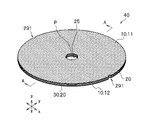
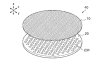
- FIG. 1A is a perspective view of the separation module 40 of the present embodiment.
- the direction of the straight line connecting the notches 291,291 formed at both ends of the diameter is perpendicular to the x direction and the plane direction of the support 20 is perpendicular to the x direction.
- the direction is the y direction, the x direction, and the direction perpendicular to the y direction, and the thickness direction of the filter 10 (described later) is the z direction.
- the separation module 40 separates, for example, the fluid T to be separated (slurry or the like) containing metal particles of a desired size from the fluid L1 (slurry or the like) to be separated containing metal particles of various sizes.
- the separation module 40 allows, for example, wet classification of metal particles, enabling particle sieving.
- the separation module 40 includes a filter 10 and a support 20.
- FIG. 1B is a sectional view taken along line AA of FIG. 1A.
- the filter 10 is, for example, a first filter 11 arranged (supported) on one side (upper surface in the illustrated example) of the support 20 configured in a disk shape, and the other side (in the illustrated example) of the support 20.
- a second filter 12 arranged (supported) on the lower surface) is included.
- the support 20 includes, for example, a laminated first support 21 and a second support 22, and a spacer 30. Although details will be described later, a space 24 is formed inside the support 20, that is, between the first support 21, the second support 22, and the spacer 30 in the illustrated example.
- the fluid T to be separated separated by the first filter 11 and the second filter 12 flows into the space 24 through the support hole 23.
- the fluid T to be separated in the space 24 is taken out from the separation module 40 through the extraction port 25.
- first filter 11 and the second filter 12 are the same except that the arrangement side with respect to the space 24 is different, the first filter 11 and the second filter 12 are centered on the first filter 11 for the sake of simplification of the description. explain. Further, since the first support 21 and the second support 22 have the same configuration except that the arrangement side with respect to the space 24 is different, the first support centering on the first support 21 is used for simplification of the explanation. The body 21 and the second support 22 will be described.
- the filter 10 has a filter hole 14 extending linearly along the thickness direction.
- the filter hole 14 is provided with an opening 111 on the surface side (opposite to the support 20) and an opening 112 on the center side (arrangement side of the support 20).
- the filter hole 14 has a predetermined inner diameter, and the fluid T to be separated flows from the surface side to the center side through the filter hole 14, so that the fluid T to be separated is separated.
- the filter 10 is made of an organic material such as a resin (polycarbonate, polyester, polyimide, etc.) or a metal material such as a single metal (copper, etc.) or an alloy. Among these, by using an organic material, the filter 10 can be easily handled, molded, attached to the support 20, and the like. On the other hand, by using a metal material, the fluid T to be separated can be stably separated even for a fluid to be separated, for example, a strong alkali.
- a resin polycarbonate, polyester, polyimide, etc.
- a metal material such as a single metal (copper, etc.) or an alloy.
- the filter 10 is preferably made of a material different from the fluid T to be separated contained in the fluid L1 to be separated. Specifically, for example, when separating metal particles having a desired size as the fluid T to be separated from the fluid L1 to be separated containing the metal particles, it is preferable that the filter 10 is made of an organic material. By doing so, contamination of the fluid to be separated T due to the constituent material of the filter 10 can be suppressed.
- the thickness direction, which is the extending direction of the filter hole 14, is the direction in which the fluid T to be separated flows through the filter hole 14, that is, the permeation direction of the fluid T to be separated. Further, the thickness direction, which is the extending direction of the filter hole 14, is the z direction shown in the figure, which is the thickness direction of the filter 10, and is a direction perpendicular to the surface direction (x direction and y direction) of the filter 10. be.
- the extending direction of the filter hole 14 does not have to exactly coincide with the z direction, and may extend diagonally with a predetermined angle such as 1 ° to 10 ° with respect to the z direction.
- the filter hole 14 extends linearly so as to penetrate the filter 10.
- linear means that, for example, the inner wall is smoothly formed and extends in the same direction from one side to the other.
- the extending direction of the filter hole 14 may differ depending on the position in the z direction as long as the effect of the present invention is not significantly impaired.
- the inner diameter of the filter hole 14 is preferably the same from one side to the other side, but the z direction is within a range that does not significantly impair the effect of the present invention, such as increasing from the surface side to the center side. It may be different depending on the position of.
- the inner wall of the filter hole 14 may be composed of only a flat surface or a curved surface, or may be configured to include both a flat surface and a curved surface. Since the filter holes 14 extend linearly, when the fluid T to be separated flows through the filter holes 14, it is possible to prevent the fluid T to be separated from being caught on the inner wall and clogging, and stable separation can be achieved over a long period of time. Performance can be maintained.
- the method for forming the filter hole 14 is not particularly limited, and may be appropriately selected depending on the material of the filter 10.
- a linear filter hole 14 can be formed, for example, by irradiating a laser beam having a beam diameter of a desired size.
- a linear filter hole 14 can be formed by, for example, etching.
- the inner diameter of the filter hole 14 can be controlled by, for example, the etching time, the composition of the etching solution, and the like.
- the inner diameter of the filter hole 14 is not particularly limited, but is, for example, 1 nm or more, preferably 5 nm or more, and the upper limit thereof is, for example, 1 mm or less, preferably 500 ⁇ m or less, more preferably 1 ⁇ m or less, still more preferably 500 nm or less, particularly preferably. It is 200 nm or less.
- the inner diameter of the filter hole 14 refers to the distance of the shortest portion of the filter hole 14 that determines the size of, for example, particles contained in the fluid T to be separated, and is circular when viewed from above. Refers to the distance between two opposing sides when it has an inner diameter, a rectangular angle, or the like.
- the support 20 supports the filter 10 on a surface, and has a support hole 23 extending linearly along the z direction (thickness direction of the filter 10) on the support surface of the filter 10.
- the support of the filter 10 is performed by, for example, sticking, adhering, welding, or the like of the filter 10 to the surface of the support 20.
- “extending linearly along the thickness direction of the filter 10” is the same as the description in the above filter 10.
- the openings 231 are all the same size and shape, but may be partially different.
- the support 20 has a higher rigidity than the filter 10.
- the support 20 is made of a resin such as polystyrene or polycarbonate.
- the support hole 23 is provided with an opening 231 on the surface side (arrangement side of the filter 10) and an opening 232 on the center side (opposite side of the filter 10). Of these, the opening 231 is formed on the support surface of the filter 10.
- the support hole 23 is, for example, a perfect circle when viewed from above.
- the opening 112 on the support 20 side of the filter hole 14 overlaps with the opening 231 on the filter 10 side of the support hole 23.
- the fluid T to be separated that has flowed through the filter hole 14 and reached the support 20 can further flow through the support hole 23.
- the inner diameter of the support hole 23 is larger than the inner diameter of the filter hole 14, for example, 1 mm or more and 10 mm or less. By doing so, the fluid T to be separated after being separated by the filter 10 can flow into the support hole 23 without excessively increasing the pressure loss.
- the support 20 includes a space 24 formed inside the support 20 and connected to the support hole 23, and an extraction port 25 communicating with the space 24.
- the extraction port 25 is provided with an opening 251 on the surface side (arrangement side of the filter 10) and an opening 252 on the center side (side facing the space 24).
- the space 24 is arranged between the first support 21 and the second support 22. By doing so, the space 24 can be formed by laminating the first support 21 and the second support 22 configured as separate bodies, so that the space 24 can be easily formed. Above all, in the illustrated example, the space 24 is arranged between the first support 21, the second support 22, and the spacer 30. By doing so, the space 24 can be formed by laminating the first support 21, the spacer 30, and the second support 22 which are separately configured, so that the space 24 can be easily formed.
- the support 20 is sandwiched between the first filter 11 and the second filter 12. As a result, the fluid T to be separated can be separated from both sides of the support 20, so that the separation efficiency can be improved.
- the support 20 has a disk shape, and the extraction port 25 is arranged at a position including the center P (FIG. 1A) of the support 20.
- the fluid T to be separated that has flowed into the space 24 through the filter hole 14 and the support hole 23 arranged so as to surround the extraction port 25 can easily flow toward the extraction port 25 arranged in the center. can.
- the separation module 40 can be rotated around the rotation axis extending in the z direction through the extraction port 25.
- the extraction port 25 is, for example, a perfect circle when viewed from above.
- FIG. 2 is an exploded perspective view of the separation module 40 of the present embodiment.
- the support holes 23 are arranged at equal intervals in the circumferential direction and the radial direction so as to surround the extraction port 25.
- the spacer 30 is sandwiched between the first support 21 and the second support 22.
- a space 24 (FIG. 1B) is formed between the first support 21, the second support 22, and the spacer 30.
- the space 24 can be formed by laminating the first support 21, the spacer 30, and the second support 22 which are separately configured, so that the space 24 can be easily formed. ..
- the size of the space 24 can be easily changed by changing the height of the spacer 30 (the same direction as the thickness direction of the filter 10).
- the spacer 30 is annular, and in the illustrated example, the outer diameter of the spacer 30 and the outer diameter of the support 20 coincide with each other. Further, the spacer 30 includes a plurality of branches 31 at equal intervals from the outer peripheral portion of the annular shape toward the center P (FIG. 1A). Since the branch 31 can support up to the vicinity of the central portion of the first support 21 and the second support 22, the strength of the separation module 40 can be improved.
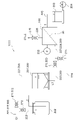
- FIG. 3 is a schematic diagram of the separation device 100 of the present embodiment.
- the separation device 100 includes, for example, a replaceable separation module 40, and is, for example, a classification device for inorganic particles contained in the separation target fluid L1.
- the inorganic particles are, for example, metal particles, and the metal particles include particles of a simple substance of a metal or a particle of a metal compound, and specifically, for example, particles of a simple substance of a metal, particles of a metal oxide, and the like. In the following, for the sake of brevity, the inorganic particles are assumed to be metal particles.
- the separation device 100 is, for example, a classification device for organic particles contained in the fluid L1 to be separated.
- Organic particles include, for example, resin particles.
- the separation module 40 can be replaced with another separation module 40.
- the number of separation modules 40 is only one, but may be two or more.
- the number of separation modules 40 to be installed can be determined, for example, according to a desired filtration area.
- the separation device 100 includes a housing 60 that rotatably houses the separation module 40 and a rotation mechanism 50 that rotates the separation module 40. By driving the rotation mechanism 50, the separation module 40 rotates inside the housing 60. do.
- the rotation mechanism 50 is, for example, a motor. Although the details will be described later, the separation of the fluid T to be separated from the fluid L1 to be separated is performed while rotating the separation module 40. Therefore, by providing the rotation mechanism 50, it is possible to improve the separation efficiency by utilizing the shearing force generated by the rotation and suppressing the sticking of the cake to the filter 10 (that is, the occurrence of fouling) by the rotation.
- the housing 60 is airtightly configured and has a space 61 inside.
- the housing 60 includes a supply port 63 for the fluid L1 to be separated, a discharge port 64 for the fluid C1 to be processed, and a discharge port 65, both of which are connected to the space 61.
- the discharge port 65 extracts the fluid L1 to be separated or the fluid C1 to be processed (which may be both) overflowing from the space 61, and the discharge port 65 can suppress an excessive pressure rise in the space 61.
- baffle plates 62 are provided inside the space 61, baffle plates 62 are provided above and below the separation module 40, respectively.
- the baffle plate 62 can suppress the fluid L1 to be separated from simply flowing in the circumferential direction in the space 61 with the rotation of the separation module 40, and can promote the separation by the separation module 40.
- a cylinder 70 is connected to one end (upper surface side of the separation module 40 in the illustrated example) of the extraction port 25 (FIG. 1A) of the separation module 40, and to the other end (lower surface side of the separation module 40 in the illustrated example).
- the closing member 71 is connected.
- the cylinder 70 is detachably connected to the separation module 40. Thereby, for example, the separation module 40 that has deteriorated over time can be replaced with another separation module 40.
- a rotation mechanism 50 is connected to the cylinder 70, and the rotation of the cylinder 70 by driving the rotation mechanism 50 causes the separation module 40 to which the cylinder 70 is connected to rotate.
- the cylinder 70 is provided with a discharge port 72 for the fluid to be separated T on the side opposite to the connection side of the separation module 40.
- the separation method by the separation device 100 will be described.
- the fluid L1 to be separated is supplied to the space 61 through the supply port 63.
- a shearing force is generated in the fluid L1 to be separated in contact with the rotating separation module 40, and the fluid T to be separated easily flows through the filter 10 (FIG. 1B).
- the pressure of the fluid L1 to be separated is increased to some extent due to the supply pressure of the fluid L1 to be separated to the space 61. That is, a differential pressure is generated between the supply side of the fluid L1 to be separated and the discharge side of the fluid T to be separated. Therefore, the fluid T to be separated passes through the filter 10 and the fluid T to be separated flows into the space 24 (FIG.
- the fluid T to be separated in the space 24 is taken out from the discharge port 72 opened to the atmosphere, for example, through the extraction port 25 and the cylinder 70.
- the fluid C1 to be treated which is the residue of the fluid L1 to be separated after the T body to be separated is separated, is taken out through the discharge ports 64 and 65.
- FIG. 4 is a system diagram of the separation system 1000 of the present embodiment.
- the separation system 1000 is a dead-end system that separates the fluid to be separated T by continuously supplying the fluid L1 to be separated to the separation device 100 or by supplying the cleaning liquid L2 after the supply of the fluid L1 to be separated is stopped.
- the cleaning liquid L2 is preferably the same type as the solvent or liquid that dissolves or disperses the fluid T to be separated in the fluid L1 to be separated.
- the cleaning liquid L2 is a pH adjuster or a dispersant.
- a solution containing a predetermined additive such as water and water is preferable.
- a predetermined additive such as water and water
- the dilution of the predetermined additive can be suppressed in the fluid T to be separated, and the dispersion of the metal particles can be maintained.
- the cleaning liquid L2 may be a solvent such as water as long as it can exert a desired effect.
- the separation system 1000 includes a separation device 100, a tank 201 accommodating the fluid L1 to be separated, a tank 202 accommodating the cleaning liquid L2, and a tank 203 accommodating the fluid T to be separated.
- the tank 202 may be a plurality of tanks containing at least one of each component constituting the cleaning liquid L2. That is, for example, the pH adjuster, the classifier, and water may be stored in different tanks and supplied to the separation device 100 independently from each tank.
- the separation system 1000 includes systems 221,222 for supplying the pressurized gas G1 (for example, high-pressure nitrogen gas) to the tanks 201 and 202, respectively, and the systems 221,222 each have a valve 271 for controlling the flow of the pressurized gas G1. , 272.
- the separation system 1000 includes systems 223 and 224 that supply the separation target fluid L1 and the cleaning liquid L2 housed in the tanks 201 and 202 to the space 61 (FIG. 3) of the separation device 100, respectively.
- the separation system 1000 includes a system 225 that supplies the fluid T to be separated separated by the separation device 100 to the tank 203, and a system 226 that discharges the fluid C1 to be processed generated by the separation device 100 and the cleaning liquid L2 after use to the outside. To prepare for.
- the system 226 includes a valve 276.
- the separation system 1000 includes a pressure gauge 233 for measuring the pressure in the space 61 (FIG. 3) and a mass gauge 234 for measuring the mass of the fluid T to be separated.
- a pressure gauge 233 for measuring the pressure in the space 61
- a mass gauge 234 for measuring the mass of the fluid T to be separated.
- the separation system 1000 includes a supply device 300 that supplies the separation device 100 with a fluid L1 to be separated having a higher pressure than the discharge side (the side of the tank 203) of the fluid T to be separated.
- a differential pressure is generated in the separation module 40 by the supply device 300, so that separation is performed using the differential pressure as a driving force.
- the supply device 300 includes a system 221,223, valves 271,273 and a tank 201, and the gas phase is boosted by supplying the pressurized gas G1 to the gas phase of the tank 201, which is a liquid phase.
- the separation target fluid L1 is extruded and supplied to the separation device 100.
- the supply device 300 may be a decompression device (not shown) that depressurizes the discharge side of the fluid T to be separated to, for example, a vacuum. Even when the decompression device is provided, the fluid L1 to be separated can be supplied at a pressure higher than that on the decompressed discharge side.
- the fluid L1 to be separated and the cleaning liquid L2 may be supplied by using a liquid feed pump (not shown) instead of supplying the pressurized gas G1 or together with the supply of the pressurized gas G1.
- the fluid L1 to be separated contained in the tank 201 is supplied to the separation device 100 through the system 223. Will be done.
- the fluid T to be separated is separated by the rotating separation module 40 (FIG. 1A) and supplied to the tank 203 through the system 225.
- the residual fluid C1 to be treated is discharged to the outside through the system 226.
- the fluid L1 to be separated is continuously supplied, and the fluid T to be separated is continuously separated.
- valves 271,273 are opened, and the valves 272,274,276 are closed, the pressurized gas G1 is passed through the system 221.
- the separation target fluid L1 housed in the tank 201 is supplied to the separation device 100 through the system 223. Since the valve 276 is closed, the pressure is high in the space 61 (FIG. 1B) of the separator 100. In this state, the valves 271,273 are closed and the supply of the fluid L1 to be separated is stopped. Then, the valves 272,274,276 are opened, and the supply of the cleaning liquid L2 is started.
- the separation device 100 separates the fluid to be separated T by the shearing force and the pressurization of the separation target fluid L1 in the separation device 100 due to the supply of the cleaning liquid L2. ..
- the fluid C1 to be treated, which is a residue, is discharged to the outside through the system 226.
- the separation module 40 According to the separation module 40, the separation device 100, and the separation system 1000 as described above, clogging of the filter 10 can be suppressed, and particles of a desired size can be continuously separated for a long period of time.
- the particle size of particles used in metal pastes of electronic materials and chemical materials is nano-sized. Nano-sized particles can be classified to have the same particle size to improve their characteristics and add value. Therefore, by using the separation module 40 to prepare and use a fluid to be separated (for example, slurry) containing particles having a uniform particle size, the characteristics of the particles can be utilized in a product using the fluid to be separated such as a capacitor. ..
- FIG. 5 is a system diagram of the separation system 1100 of another embodiment.
- the separation system 1100 separates by a diafiltration method.
- the separated fluid T is separated by adding the cleaning liquid L2 in the same amount as the amount of the separated fluid T obtained while circulating the separated target fluid L1 to the separated target fluid L1. Therefore, the separation rate and the separation efficiency can be maintained for a long period of time.
- the separation system 1100 has the same basic configuration as the separation system 1000 (FIG. 4) except that it includes a supply device 301 such as a liquid feed pump instead of the supply device 300 (FIG. 4). However, the separation system 1100 further includes a flow meter 235 that measures the flow rate of the cleaning liquid L2 flowing through the system 224, and a mass meter 236 that measures the mass of the fluid in the tank 201. Feedback control is performed for the opening degree of the valve 274 while measuring the flow rate with the flow meter 235 so that the mass measured by the mass meter 236 is constant.
- the separation device 100 By driving the supply device 301, the separation device 100 produces a circulating fluid C3 whose flow rate is reduced by the amount of the fluid T to be separated.
- the circulating fluid C3 is supplied to the tank 201 through a system 227 equipped with a valve 277. Further, the tank 201 is supplied with the same amount of cleaning liquid L2 as the reduced fluid T to be separated through the system 224. As a result, a constant flow rate of the fluid L1 to be separated is supplied to the separation device 100, and stable separation can be continuously performed in the separation device 100.
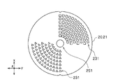
- FIG. 6 is a top view of the first support 21 constituting the separation module 40 (FIG. 1A) of another embodiment.
- the shape and arrangement location of the openings 231,251 are not particularly limited.
- the opening 231 is not formed on the entire surface unlike the example of FIG. 1A, and the shapes of the openings 231 are not all the same but are partially different.
- the openings 231 are arranged symmetrically about the opening 251 and have a rectangular shape (for example, a square) on one side and a triangle (for example, an equilateral triangle) on the other side.
- the openings 231 are arranged in 90 ° regions, which are ranges in the x-direction and the y-direction, respectively.
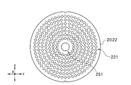
- FIG. 7 is a top view of the first support 21 constituting the separation module 40 (FIG. 1A) of another embodiment.
- the size of the opening 231 is not particularly limited. In the example of FIG. 7, the opening 231 is formed on the entire surface of the first support 21, but unlike the example of FIG. 1A, it has various sizes. Specifically, in the example of FIG. 7, the opening 231 has various sizes and has various shapes such as a rhombus, a circle, and a square.
- FIG. 8A is a top view of the first support 21 constituting the separation module 40 (FIG. 1A) of another embodiment.
- the opening 231 and the opening 232 do not have to be at the same position in the x direction and the y direction, that is, at the same position on the front and back, and the opening 231 and the opening 232 are arranged at different positions on the front and back.
- four openings 231 are arranged with the opening 251 as a symmetry.
- FIG. 8B is a sectional view taken along line BB of FIG. 8A.
- the white arrow indicates the rotation direction R of the separation module 40 (FIG. 1A) with respect to the support hole 23 in the figure, and the broken line arrow indicates the relative movement direction P1 of the separation target fluid L1 during rotation of the separation module 40. show.
- the separation target fluid L1 does not necessarily have to actually move in the direction of the broken line arrow, and the broken line arrow indicates the flow direction of the separation target fluid L1 as seen from the rotating separation module 40.
- the support hole 23 is arranged at an angle with respect to the z direction, unlike the example shown in FIG. 1B above. That is, the support hole 23 is arranged in an oblique direction with respect to the z direction, which is the thickness direction of the filter 10, and the support hole 23 has an inclination downward to the left of the paper surface. However, the support hole 23 may have an inclination downward to the right of the paper surface.
- the inner wall of the support hole 23 may have a streamlined shape.
- the first support 21 of this embodiment is suitable for the rotating separation module 40. Therefore, for example, the separation device 100 shown in FIG. 3 includes a separation module 40 including the first support 21 shown in FIGS. 8A and 8B.
- the support hole 23 has an inclination that goes up in the rotation direction R (direction of the white arrow) driven by the rotation mechanism 50 (FIG. 3). By configuring the support hole 23 in this way, the fluid T to be separated (FIG. 3) can be easily flowed into the support hole 23 during rotation, and an increase in pressure loss can be suppressed.
- FIG. 9 is a top view of the first support 21 constituting the separation module 40 (FIG. 1A) of another embodiment.
- the first support 21 and the second support 22 have the same configuration, but may have different configurations.
- the first support 21 shown in FIG. 9 has the same shape of the inner edge and the outer edge as the second support 22 shown in FIG. A circular opening 231 is arranged.
- FIG. 10 is a top view of the second support 22 that can be used in combination with the first support 21 of FIG.
- the second support 22 shown in FIG. 10 has a different configuration from the first support 21 shown in FIG. 9, and specifically, for example, the shape of the opening 231 is different.
- rhombic openings 231 are arranged on the entire surface at equal intervals in the circumferential direction and the radial direction with the opening 251 as the center. Even if the first support 21 and the second support 22 have different configurations, the separation module 40 can be configured.
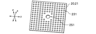
- FIG. 11 is a perspective view of the first support 21 constituting the separation module 40 (FIG. 1A) of another embodiment.
- the first support 21 is a perfect circle when viewed from above, but the shape of the first support 21 is not limited to a perfect circle.
- the first support 21 in FIG. 11 has a rectangular shape when viewed from above, and more specifically, has a square shape.
- the openings 231 are arranged at equal intervals on the entire surface of the square first support 21 so as to surround the openings 251.
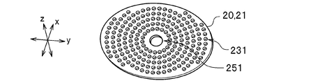
- FIG. 12 is a perspective view of the first support 21 constituting the separation module 40 (FIG. 1A) of another embodiment.
- the first support 21 of FIG. 12 has a circular shape in a top view as in FIG. 1A, but unlike FIG. 1A, it has an elliptical shape.
- the openings 231 are arranged at equal intervals on the entire surface of the elliptical first support 21 so as to surround the openings 251.
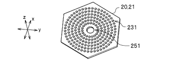
- FIG. 13 is a perspective view of the first support 21 constituting the separation module 40 (FIG. 1A) of another embodiment.
- the first support 21 of FIG. 13 has a polygonal shape as in FIG. 11, but unlike FIG. 11, it has a hexagonal shape, and more specifically, it has a regular hexagonal shape.
- the openings 231 are arranged at equal intervals on the entire surface of the regular hexagonal first support 21 so as to surround the openings 251.
- FIG. 14 is a perspective view of the first support 21 constituting the separation module 40 (FIG. 1A) of another embodiment.
- the first support 21 of FIG. 14 has a polygonal shape as in FIG. 11, but unlike FIG. 11, it has a shape in which convex portions 292 and concave portions 293 are alternately formed on the edges.
- the openings 231 are arranged at equal intervals so as to surround the openings 251 on the entire surface of the first support 21 having a shape in which the convex portions 292 and the concave portions 293 are alternately formed.
- FIG. 15 is a perspective view of the first support 21 and the second support 22 constituting the separation module 40 (FIG. 1A) of another embodiment.
- the separation module 40 shown in FIG. 1A is provided with a spacer 30 (FIG. 1A), but the separation module 40 shown in FIG. 15 does not include the spacer 30 and a space 24 (FIG. 1B) is formed inside.
- An annular convex portion 262 is arranged on the lower surface 261 of the first support 21, for example, along the edge (not necessarily along the edge).
- the first support 21 having such a shape can be formed, for example, by hollowing out a cylinder.
- the first support 21 and the second support 22 are laminated so that the convex portion 262 is in contact with the upper surface 263 of the disk-shaped second support 22.
- the convex portion 262 and the upper surface 263 are attached, adhered or welded.
- a space 24 is formed between the lower surface 261 and the convex portion 262 and the upper surface 263.
- FIG. 16 is a perspective view of the first support 21 and the second support 22 constituting the separation module 40 (FIG. 1A) of another embodiment. Similar to FIG. 15 above, the separation module 40 shown in FIG. 16 does not include the spacer 30 (FIG. 1A), and a space 24 (FIG. 1B) is formed therein.
- a plurality of columnar (for example, columnar) protrusions 264 are arranged at equal intervals in the circumferential direction.
- An annular, for example, plate-shaped elastic body 267 is arranged so as to surround the plurality of protrusions 264.
- the first support 21 and the second support 22 are laminated with the elastic body 267 interposed therebetween so that the protrusion 264 is in contact with the lower surface 261 of the disk-shaped first support 21.
- the protrusion 264 and the lower surface 261 are attached, adhered or welded.
- a space 24 is formed between the lower surface 261 and the upper surface 263, the protrusion 264, and the elastic body 267.
- FIG. 17A is a perspective view of the support 20 constituting the separation module 40 (FIG. 1A) of another embodiment.
- the support 20 includes the first support 21 and the second support 22 configured separately, but the support 20 in FIG. 17A is the first support 21 and the second support 22. It is not divided into two parts, but is molded as an integral member. Openings 231 and 231 are formed on the upper surface 265 and the lower surface 266 of the support body 20 in the same manner as the support body 20 of each of the above examples.
- FIG. 17B is a sectional view taken along line CC of FIG. 17A.
- the support 20 shown in FIG. 17B is an integrally molded product. By doing so, the airtightness of the space 24 is enhanced, so that the pressure in the space 24 can be increased to improve the separation performance.
- the support 20 can be formed by, for example, a 3D printer or the like.
- FIG. 18 is an exploded perspective view of the separation module 40 of another embodiment.
- the support 20 includes, for example, a first support 21 and a second support 22 formed in a rectangular shape.
- the separation module 40 shown in FIG. 18 does not have a space 24 (FIG. 1B) between the first support 21 and the second support 22, and does not have an extraction port 25. Therefore, in this embodiment, the fluid T to be separated is obtained from the other surface side by the contact of the fluid L1 to be separated with the one surface side of the separation module 40.
- the filter 10 is formed to have the same shape and size as the first support 21 and the second support 22, and is sandwiched between the first support 21 and the second support 22. By doing so, the support strength of the filter 10 can be improved.
- the filter 10 is attached to, adhered to or welded to at least one of the first support 21 and the second support 22.
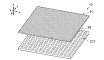
- FIG. 19 is an exploded perspective view of the separation module 40 of another embodiment.
- the support 20 is configured in a rectangular shape as in the example of FIG. 18, but unlike the example of FIG. 18, it is configured in a single shape.
- the filter 10 is formed in the same shape and size as the support 20, and is supported on, for example, the upper surface of the support 20 in the illustrated example, but may be supported on the lower surface.
- FIG. 20A is a diagram illustrating a separation method by the separation device 100 of another embodiment.
- the separation device 100 includes, for example, a mounting table 80 formed in a rectangular shape in a top view, and housings 81, 82, 83 having spaces 61, 61 in which the fluid L1 to be separated is supplied.
- the mounting table 80 is provided with, for example, a mounting table hole (not shown) for mounting a rectangular separation module 40 and discharging the fluid T to be separated on the side opposite to the supply side of the fluid L1 to be separated.
- the mounting table 80 is made of, for example, a resin plate having mesh holes, punching metal, or the like.
- the housings 81, 82, and 83 are vertically separated from each other with the mounting table 80 as a boundary, and are connected to actuators (not shown). By driving the actuator, the housings 81, 82, and 83 are separated in the vertical direction.
- the housings 81, 82, and 83 each include supply ports 811, 821 for supplying the fluid L1 to be separated to the space 61 (the supply ports provided in the housing 83 are not shown).
- Each of the housings 81, 82, and 83 includes a discharge port 822,832 (the discharge port provided in the housing 81 is not shown) for discharging the fluid T to be separated.
- the housings 81, 82, and 83 each include a supply port 833, 823, 833 for supplying the dry gas G2 (FIG. 20B, for example, air) to the space 61.
- the separation device 100 further includes an exchange mechanism 89 (FIG. 20C) for exchanging the separation module 40 mounted on the mounting table 80 with another separation module 40.
- the exchange mechanism 89 includes, for example, a hydraulic suction cup (not shown) in which the separation module 40 can be attached and detached by suction, and the separation module 40 is exchanged by holding and transferring the separation module 40 by the suction cup.
- the separation device 100 includes, for example, a shelf (not shown) on which the separation module 40 mounted on the mounting table 80 is placed, and the exchange mechanism 89 transfers the placed separation module 40 to the mounting table 80.
- the separation module 40 shown in FIG. 18 is used, but the separation module 40 shown in FIG. 19 may be used.
- the separation module 40 shown in FIG. 19 it is preferable to arrange the separation module 40 so that the support 20 is in contact with the mounting table 80.
- the fluid T to be separated is obtained by distribution to the separation module 40.
- the residue cake (not shown) remains on the space 61 side of the separation module 40 (upper surface in the illustrated example).
- FIG. 20B is a diagram illustrating a separation method by the separation device 100 of another embodiment.
- the supply of the fluid L1 to be separated (FIG. 20A) to the space 61 is stopped by closing the valve (not shown) on the pipe (not shown) connected to the supply ports 811, 821 and the like.
- the dry gas G2 is supplied in this state, the fluid T to be separated in the fluid L1 to be separated flows through the separation module 40 due to the gas pressure of the dry gas G2 and is discharged. At the same time, the cake on the separation module 40 is dried.
- FIG. 20C is a diagram illustrating a separation method by the separation device 100 of another embodiment.
- the housings 81, 82, and 83 are separated in the vertical direction by driving an actuator (not shown).
- the exchange mechanism 89 transfers the separation module 40 mounted on the mounting table 80 from the mounting table 80 to the left on the paper surface, and mounts a new separation module 40 on the mounting table 80.
- the separation device 100 returns to the state shown in FIG. 20A.
- the separation module 40 whose separation performance has deteriorated due to the accumulation of cake can be exchanged with a new separation module 40 by the exchange mechanism 89, and the deterioration of the separation performance in the separation device 100 can be suppressed.
- FIG. 21 is an exploded perspective view of the separation module 40 of another embodiment.
- the support 20 of FIG. 21 is the same as the example of FIG. 18 except that the support 20 is formed in a circular shape when viewed from above.
- FIG. 22 is an exploded perspective view of the separation module 40 of another embodiment.
- the support 20 of FIG. 22 is the same as the example of FIG. 19 except that the support 20 is formed in a circular shape when viewed from above.
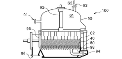
- FIG. 23A is a diagram illustrating a separation method by the separation device 100 of another embodiment.
- the separation device 100 includes, for example, a mounting table 80 formed in a circular shape in a top view and a housing 90 having a space 61 inside, and the housing 90 is composed of, for example, a pressure vessel.
- the mounting table 80 is mounted on the bottom plate 98 (for example, a steel plate) of the housing 90.
- the housing 90 further supplies the supply port 91 for supplying the fluid L1 to be separated to the space 61, the squeezing mechanism 92 for squeezing the cake C2 (FIG. 23B) deposited on the separation module 40, and the dry gas G2 to the space 61.
- the housing 90 further includes discharge ports 96 and 97 for discharging the cake C2 accumulated inside (see FIG. 23C for the discharge port 97), and a lid 95 for closing the discharge port 97.
- the separation module 40 shown in FIG. 21 is used, but the separation module 40 shown in FIG. 22 may be used.
- the separation module 40 shown in FIG. 22 it is preferable to arrange the separation module 40 so that the support 20 is in contact with the mounting table 80.
- the fluid L1 to be separated is supplied to the space 61 with the discharge port 97 closed, the fluid T to be separated is obtained, and the residue cake C2 (FIG. 23B) is the separation module. For example, it remains on the upper surface of 40.
- FIG. 23B is a diagram illustrating a separation method by the separation device 100 of another embodiment.
- the supply of the fluid L1 to be separated to the space 61 is stopped by closing the valve (not shown) on the pipe (not shown) connected to the supply port 91.
- the pressing mechanism 92 is driven while supplying the drying gas G2 in this state, the cake C2 is dried.
- FIG. 23C is a diagram illustrating a separation method by the separation device 100 of another embodiment.
- the discharge port 97 opens.
- the accumulated cake C2 can be removed by, for example, scraping the cake C2 through the discharge ports 96 and 97.
- the separation module 40 may be separated again without being replaced, or the separation module 40 may be replaced with another separation module (for example, a new one) and then the separation may be performed.
- the replacement is usually performed manually, but may be performed by, for example, a replacement mechanism 89 (FIG. 20C).
Abstract
La présente invention concerne un module de séparation dont le colmatage peut être supprimé. Afin de résoudre ce problème, le module de séparation 40, qui sépare un fluide T d'un fluide L1 soumis à une séparation, comprend : un filtre 10 constitué d'un matériau organique ou d'un matériau métallique et comprenant des trous de filtre 14 s'étendant chacun en ligne droite le long de la direction de l'épaisseur ; et un support 20 qui supporte le filtre 10 sur une surface et comprend des trous de support 23 s'étendant chacun en ligne droite le long de la direction de l'épaisseur, un chevauchement existant entre des ouvertures 112 des trous de filtre 14 sur le côté de support 20 et des ouvertures des trous de support 23 sur le côté de filtre 10.
Priority Applications (3)
| Application Number | Priority Date | Filing Date | Title |
|---|---|---|---|
| JP2022560619A JPWO2022097295A1 (fr) | 2020-11-09 | 2020-11-09 | |
| PCT/JP2020/041699 WO2022097295A1 (fr) | 2020-11-09 | 2020-11-09 | Module de séparation, dispositif de séparation, et système de séparation |
| TW110128333A TW202218727A (zh) | 2020-11-09 | 2021-08-02 | 分離模組、分離裝置以及分離系統 |
Applications Claiming Priority (1)
| Application Number | Priority Date | Filing Date | Title |
|---|---|---|---|
| PCT/JP2020/041699 WO2022097295A1 (fr) | 2020-11-09 | 2020-11-09 | Module de séparation, dispositif de séparation, et système de séparation |
Publications (1)
| Publication Number | Publication Date |
|---|---|
| WO2022097295A1 true WO2022097295A1 (fr) | 2022-05-12 |
Family
ID=81457677
Family Applications (1)
| Application Number | Title | Priority Date | Filing Date |
|---|---|---|---|
| PCT/JP2020/041699 WO2022097295A1 (fr) | 2020-11-09 | 2020-11-09 | Module de séparation, dispositif de séparation, et système de séparation |
Country Status (3)
| Country | Link |
|---|---|
| JP (1) | JPWO2022097295A1 (fr) |
| TW (1) | TW202218727A (fr) |
| WO (1) | WO2022097295A1 (fr) |
Citations (6)
| Publication number | Priority date | Publication date | Assignee | Title |
|---|---|---|---|---|
| JP2007536071A (ja) * | 2004-05-03 | 2007-12-13 | フリースランド・ブランズ・ビー・ヴイ | 担体上に膜を持つデバイス、そしてそのような膜を製造するための方法 |
| JP2009518183A (ja) * | 2005-12-07 | 2009-05-07 | ゼネラル・エレクトリック・カンパニイ | 膜構造と製造方法 |
| JP2015521103A (ja) * | 2012-05-16 | 2015-07-27 | ザ リージェンツ オブ ザ ユニバーシティ オブ カリフォルニア | 低抵抗微細加工フィルタ |
| WO2016140005A1 (fr) * | 2015-03-03 | 2016-09-09 | 株式会社村田製作所 | Corps poreux et dispositif de filtre |
| JP2017029974A (ja) * | 2015-05-11 | 2017-02-09 | ポール・コーポレーションPall Corporation | 液体処理モジュールおよび液体処理アセンブリ |
| US20190070566A1 (en) * | 2016-11-04 | 2019-03-07 | Massachusetts Institute Of Technology | Techniques for performing diffusion-based filtration using nanoporous membranes and related systems and methods |
-
2020
- 2020-11-09 WO PCT/JP2020/041699 patent/WO2022097295A1/fr active Application Filing
- 2020-11-09 JP JP2022560619A patent/JPWO2022097295A1/ja active Pending
-
2021
- 2021-08-02 TW TW110128333A patent/TW202218727A/zh unknown
Patent Citations (6)
| Publication number | Priority date | Publication date | Assignee | Title |
|---|---|---|---|---|
| JP2007536071A (ja) * | 2004-05-03 | 2007-12-13 | フリースランド・ブランズ・ビー・ヴイ | 担体上に膜を持つデバイス、そしてそのような膜を製造するための方法 |
| JP2009518183A (ja) * | 2005-12-07 | 2009-05-07 | ゼネラル・エレクトリック・カンパニイ | 膜構造と製造方法 |
| JP2015521103A (ja) * | 2012-05-16 | 2015-07-27 | ザ リージェンツ オブ ザ ユニバーシティ オブ カリフォルニア | 低抵抗微細加工フィルタ |
| WO2016140005A1 (fr) * | 2015-03-03 | 2016-09-09 | 株式会社村田製作所 | Corps poreux et dispositif de filtre |
| JP2017029974A (ja) * | 2015-05-11 | 2017-02-09 | ポール・コーポレーションPall Corporation | 液体処理モジュールおよび液体処理アセンブリ |
| US20190070566A1 (en) * | 2016-11-04 | 2019-03-07 | Massachusetts Institute Of Technology | Techniques for performing diffusion-based filtration using nanoporous membranes and related systems and methods |
Also Published As
| Publication number | Publication date |
|---|---|
| JPWO2022097295A1 (fr) | 2022-05-12 |
| TW202218727A (zh) | 2022-05-16 |
Similar Documents
| Publication | Publication Date | Title |
|---|---|---|
| CN108570662B (zh) | 喷淋板、处理装置和喷出方法 | |
| US7767151B2 (en) | High throughput mechanical alloying and screening | |
| EP2830746B1 (fr) | Dispositif plan de filtration et d'isolement et de récupération sélectifs | |
| US10821387B2 (en) | Apparatus for additive manufacturing of three-dimensional objects | |
| WO2022049718A1 (fr) | Robot de peinture | |
| JP2007283298A (ja) | 使い捨て式の接線流濾過装置保持器 | |
| CN111032218A (zh) | 颗粒捕获室、颗粒捕获芯片、颗粒捕获方法、设备和颗粒分析系统 | |
| MX2010009177A (es) | Elemento de filtro para un filtro de disco. | |
| WO2022097295A1 (fr) | Module de séparation, dispositif de séparation, et système de séparation | |
| US9669333B2 (en) | Filter module and modular filter system | |
| CA2587571A1 (fr) | Element filtrant sans cadre en forme de plaque | |
| JP2010201549A (ja) | マイクロ流路デバイス、分離方法、及び、分離装置 | |
| WO2011129746A1 (fr) | Filtre comprenant des plaquettes de filtration gaufrées empilables comprenant des canaux de filtration sur des côtés opposés des plaquettes gaufrées | |
| JP2017029974A (ja) | 液体処理モジュールおよび液体処理アセンブリ | |
| JP7254365B2 (ja) | マイクロ液滴・気泡生成デバイス | |
| JP5278884B2 (ja) | マニホールドプレートおよびマニホールドプレートを含む流体処理装置 | |
| US20210101117A1 (en) | Microfilter, manufacturing method and microfiltration unit | |
| JPH07222916A (ja) | 閉じた円筒状容器内で固体を含む液体を連続的に濾過する濾過装置 | |
| EP0378192A2 (fr) | Dispositif filtrant | |
| KR101291966B1 (ko) | 실리콘계 나노입자 포집 시스템 및 이에 사용되는 나노입자 포집/보관용기 | |
| JP2011173054A (ja) | 濾過器、およびこれを備えた塗布装置 | |
| EP1689512A1 (fr) | Ensemble plaquettes a membrane dynamique et procede | |
| UA125063C2 (uk) | Фільтрувальний елемент дискового фільтрувального пристрою | |
| US20220146441A1 (en) | Serial synchrotron crystallography sample holding system | |
| CN210646468U (zh) | 使用aao多孔膜的可扩展超滤离心管 |
Legal Events
| Date | Code | Title | Description |
|---|---|---|---|
| 121 | Ep: the epo has been informed by wipo that ep was designated in this application |
Ref document number: 20960847 Country of ref document: EP Kind code of ref document: A1 |
|
| ENP | Entry into the national phase |
Ref document number: 2022560619 Country of ref document: JP Kind code of ref document: A |
|
| NENP | Non-entry into the national phase |
Ref country code: DE |
|
| 122 | Ep: pct application non-entry in european phase |
Ref document number: 20960847 Country of ref document: EP Kind code of ref document: A1 |