WO2022097269A1 - Power conversion device - Google Patents

Power conversion device Download PDF

Info

Publication number
WO2022097269A1
WO2022097269A1 PCT/JP2020/041518 JP2020041518W WO2022097269A1 WO 2022097269 A1 WO2022097269 A1 WO 2022097269A1 JP 2020041518 W JP2020041518 W JP 2020041518W WO 2022097269 A1 WO2022097269 A1 WO 2022097269A1
Authority
WO
WIPO (PCT)
Prior art keywords
power
circuit
control
control circuit
characteristic
Prior art date
Application number
PCT/JP2020/041518
Other languages
French (fr)
Japanese (ja)
Inventor
禎之 井上
Original Assignee
三菱電機株式会社
Priority date (The priority date is an assumption and is not a legal conclusion. Google has not performed a legal analysis and makes no representation as to the accuracy of the date listed.)
Filing date
Publication date
Application filed by 三菱電機株式会社 filed Critical 三菱電機株式会社
Priority to CN202080106835.9A priority Critical patent/CN116458026A/en
Priority to PCT/JP2020/041518 priority patent/WO2022097269A1/en
Priority to JP2022560599A priority patent/JP7483037B2/en
Priority to US18/031,627 priority patent/US20230387692A1/en
Priority to TW110140280A priority patent/TWI784776B/en
Publication of WO2022097269A1 publication Critical patent/WO2022097269A1/en

Links

Images

Classifications

    • HELECTRICITY
    • H02GENERATION; CONVERSION OR DISTRIBUTION OF ELECTRIC POWER
    • H02JCIRCUIT ARRANGEMENTS OR SYSTEMS FOR SUPPLYING OR DISTRIBUTING ELECTRIC POWER; SYSTEMS FOR STORING ELECTRIC ENERGY
    • H02J3/00Circuit arrangements for ac mains or ac distribution networks
    • H02J3/38Arrangements for parallely feeding a single network by two or more generators, converters or transformers
    • H02J3/381Dispersed generators
    • HELECTRICITY
    • H02GENERATION; CONVERSION OR DISTRIBUTION OF ELECTRIC POWER
    • H02JCIRCUIT ARRANGEMENTS OR SYSTEMS FOR SUPPLYING OR DISTRIBUTING ELECTRIC POWER; SYSTEMS FOR STORING ELECTRIC ENERGY
    • H02J3/00Circuit arrangements for ac mains or ac distribution networks
    • H02J3/24Arrangements for preventing or reducing oscillations of power in networks
    • HELECTRICITY
    • H02GENERATION; CONVERSION OR DISTRIBUTION OF ELECTRIC POWER
    • H02JCIRCUIT ARRANGEMENTS OR SYSTEMS FOR SUPPLYING OR DISTRIBUTING ELECTRIC POWER; SYSTEMS FOR STORING ELECTRIC ENERGY
    • H02J3/00Circuit arrangements for ac mains or ac distribution networks
    • H02J3/38Arrangements for parallely feeding a single network by two or more generators, converters or transformers
    • H02J3/40Synchronising a generator for connection to a network or to another generator
    • HELECTRICITY
    • H02GENERATION; CONVERSION OR DISTRIBUTION OF ELECTRIC POWER
    • H02JCIRCUIT ARRANGEMENTS OR SYSTEMS FOR SUPPLYING OR DISTRIBUTING ELECTRIC POWER; SYSTEMS FOR STORING ELECTRIC ENERGY
    • H02J3/00Circuit arrangements for ac mains or ac distribution networks
    • H02J3/38Arrangements for parallely feeding a single network by two or more generators, converters or transformers
    • H02J3/46Controlling of the sharing of output between the generators, converters, or transformers
    • HELECTRICITY
    • H02GENERATION; CONVERSION OR DISTRIBUTION OF ELECTRIC POWER
    • H02MAPPARATUS FOR CONVERSION BETWEEN AC AND AC, BETWEEN AC AND DC, OR BETWEEN DC AND DC, AND FOR USE WITH MAINS OR SIMILAR POWER SUPPLY SYSTEMS; CONVERSION OF DC OR AC INPUT POWER INTO SURGE OUTPUT POWER; CONTROL OR REGULATION THEREOF
    • H02M7/00Conversion of ac power input into dc power output; Conversion of dc power input into ac power output
    • H02M7/42Conversion of dc power input into ac power output without possibility of reversal
    • H02M7/44Conversion of dc power input into ac power output without possibility of reversal by static converters
    • H02M7/48Conversion of dc power input into ac power output without possibility of reversal by static converters using discharge tubes with control electrode or semiconductor devices with control electrode
    • HELECTRICITY
    • H02GENERATION; CONVERSION OR DISTRIBUTION OF ELECTRIC POWER
    • H02JCIRCUIT ARRANGEMENTS OR SYSTEMS FOR SUPPLYING OR DISTRIBUTING ELECTRIC POWER; SYSTEMS FOR STORING ELECTRIC ENERGY
    • H02J2203/00Indexing scheme relating to details of circuit arrangements for AC mains or AC distribution networks
    • H02J2203/20Simulating, e g planning, reliability check, modelling or computer assisted design [CAD]
    • HELECTRICITY
    • H02GENERATION; CONVERSION OR DISTRIBUTION OF ELECTRIC POWER
    • H02JCIRCUIT ARRANGEMENTS OR SYSTEMS FOR SUPPLYING OR DISTRIBUTING ELECTRIC POWER; SYSTEMS FOR STORING ELECTRIC ENERGY
    • H02J2300/00Systems for supplying or distributing electric power characterised by decentralized, dispersed, or local generation
    • H02J2300/20The dispersed energy generation being of renewable origin
    • H02J2300/22The renewable source being solar energy
    • H02J2300/24The renewable source being solar energy of photovoltaic origin
    • YGENERAL TAGGING OF NEW TECHNOLOGICAL DEVELOPMENTS; GENERAL TAGGING OF CROSS-SECTIONAL TECHNOLOGIES SPANNING OVER SEVERAL SECTIONS OF THE IPC; TECHNICAL SUBJECTS COVERED BY FORMER USPC CROSS-REFERENCE ART COLLECTIONS [XRACs] AND DIGESTS
    • Y02TECHNOLOGIES OR APPLICATIONS FOR MITIGATION OR ADAPTATION AGAINST CLIMATE CHANGE
    • Y02BCLIMATE CHANGE MITIGATION TECHNOLOGIES RELATED TO BUILDINGS, e.g. HOUSING, HOUSE APPLIANCES OR RELATED END-USER APPLICATIONS
    • Y02B10/00Integration of renewable energy sources in buildings
    • Y02B10/10Photovoltaic [PV]
    • YGENERAL TAGGING OF NEW TECHNOLOGICAL DEVELOPMENTS; GENERAL TAGGING OF CROSS-SECTIONAL TECHNOLOGIES SPANNING OVER SEVERAL SECTIONS OF THE IPC; TECHNICAL SUBJECTS COVERED BY FORMER USPC CROSS-REFERENCE ART COLLECTIONS [XRACs] AND DIGESTS
    • Y02TECHNOLOGIES OR APPLICATIONS FOR MITIGATION OR ADAPTATION AGAINST CLIMATE CHANGE
    • Y02PCLIMATE CHANGE MITIGATION TECHNOLOGIES IN THE PRODUCTION OR PROCESSING OF GOODS
    • Y02P80/00Climate change mitigation technologies for sector-wide applications
    • Y02P80/20Climate change mitigation technologies for sector-wide applications using renewable energy

Definitions

  • This disclosure relates to a power conversion device.
  • energy-creating equipment energy-creating equipment using renewable energy such as solar cells
  • energy storage equipment energy storage equipment
  • a static inverter is adopted in order to connect the energy-creating equipment and the energy-storing equipment to the AC system.
  • thermal power plants which are capable of adjusting the amount of power generation in response to fluctuations in demand, will be closed in the future from the viewpoint of reducing power generation costs including management costs as the amount of power generation by renewable energy increases.
  • the synchronous generator in a thermal power plant has a potential effect (inertial force, synchronization force, etc.) of suppressing the fluctuation when the system frequency fluctuates. Therefore, if the thermal power plant is closed, the number of synchronous generators will be reduced, and it may be difficult to secure the stability of the power system.
  • Patent Document 1 discloses a method for setting control parameters of a distributed power source (static inverter) that implements virtual synchronous generator control. Specifically, Patent Document 1 describes in a distributed power source based on either a required inertial value required by a grid operator or a virtual inertial value calculated based on the specifications and operating conditions of the distributed power source. A method of generating control parameters for setting virtual inertia is disclosed.
  • the inertial force of the system intended by the system manager is guaranteed, but each of them is caused by a change in load or a change in the amount of power generated by the energy-creating device. It is not possible to guarantee the amount of power shared by distributed power sources.
  • each storage battery when the load of the entire system increases, the virtual synchronous generator control is executed in each storage battery, and the increased power is output by the two storage batteries. At that time, if the control parameters of the virtual synchronous generator control of the two storage batteries are the same, each storage battery additionally outputs the same amount of power.
  • the present disclosure has been made to solve the above-mentioned problems, and an object thereof is a power system in which a plurality of power converters having a static inverter equipped with a virtual synchronous generator control are connected.
  • each power conversion device should be equal to the ratio of the power target value notified from the upper EMS (Energy Management System). It is to generate control parameters for virtual synchronous generator control that can prorate the excess and deficiency power.
  • the power conversion device includes an inverter that converts the power output from the distributed power supply into AC power and outputs the power to the AC system, and a control circuit that controls the inverter.
  • the control circuit consists of a virtual synchronous generator control circuit that gives the inverter the transient characteristics of the synchronous generator, a control parameter generation circuit that generates control parameters for controlling the virtual synchronous generator control circuit, and a virtual synchronous generator control.
  • Information necessary for generating the power target value and control parameters of the distributed power supply from the inverter voltage control circuit that controls the inverter as the voltage source and the management device that manages the distributed power supply based on the AC system voltage information input from the circuit. Includes a communication circuit to receive.
  • the control parameter generation circuit generates at least one of the speed adjustment rate and the braking coefficient used in the virtual synchronous generator control circuit based on the power target value received by the communication circuit and the information necessary for generating the control parameter.
  • FIG. It is a figure for demonstrating the virtual synchronous generator control implemented in the power conversion apparatus which concerns on Embodiment 1.
  • FIG. It is a figure for demonstrating the virtual synchronous generator control implemented in the power conversion apparatus which concerns on Embodiment 1.
  • FIG. It is a figure which shows an example of a ⁇ F / ⁇ P characteristic. It is a figure which shows the response waveform of the frequency of the AC voltage output from the static inverter when the load is suddenly changed in the virtual synchronous generator control mounted on the power conversion apparatus which concerns on Embodiment 1.
  • FIG. It is a figure which shows the response waveform of the effective value of the AC power output from the static inverter of each of the two power conversion devices which implemented the conventional virtual synchronous generator control.
  • the response waveform of the frequency of the AC voltage output from each static inverter when two power conversion devices equipped with the conventional virtual synchronous generator control are operated is shown. It is a figure which shows an example of the ⁇ F / ⁇ P characteristic of the 1st power conversion apparatus which implemented the conventional virtual synchronous generator control. It is a figure which shows an example of the ⁇ F / ⁇ P characteristic of the 2nd power conversion apparatus which implemented the conventional virtual synchronous generator control. It is a figure which shows an example of the ⁇ F / ⁇ P characteristic of the 2nd power conversion apparatus which implemented the virtual generator control which concerns on Embodiment 1.
  • FIG. 27 It is a figure which shows an example of the reference ⁇ F / ⁇ P characteristic in the power conversion apparatus which implemented the virtual synchronous generator control which concerns on Embodiment 1.
  • FIG. 27 It is a figure for demonstrating the method of making the ⁇ F / ⁇ P characteristic of each power conversion apparatus using the reference ⁇ F / ⁇ P characteristic shown in FIG. 27.
  • FIG. 27 It is a figure for demonstrating the method of making a reference ⁇ F / ⁇ P characteristic of a static inverter with a capacity of 4kW.
  • FIG. 30 It is a figure which shows the waveform of the effective value of the AC power output from the two power conversion devices shown in FIG. 30. It is a sequence diagram for demonstrating the normal operation of the distributed power supply system shown in FIG. It is a flowchart which shows the control process of CEMS. It is a flowchart which shows the process (S05 of FIG. 33) which creates the operation plan of a storage battery. It is a flowchart which shows the process (S056 of FIG. 34) which generates the information necessary for generating the control parameter of a virtual synchronous generator control. It is a flowchart which shows the process (S0562 of FIG. 35) which generates the reference ⁇ F / ⁇ P characteristic.
  • FIG. It is a figure for demonstrating the problem in the case of controlling a power conversion apparatus according to the control parameter for virtual synchronous generator control generated in Embodiment 1.
  • FIG. It is a figure which shows an example of the ⁇ F / ⁇ P characteristic generated by changing the inclination of the reference ⁇ F / ⁇ P characteristic of the 1st power conversion apparatus. It is a figure which shows an example of the ⁇ F / ⁇ P characteristic generated by changing the inclination of the reference ⁇ F / ⁇ P characteristic of the 2nd power conversion apparatus. It is a flowchart for demonstrating the generation process of a reference ⁇ F / ⁇ P characteristic executed by CEMS.
  • FIG. 2 It is a figure which shows an example of the reference ⁇ F / ⁇ P characteristic and ⁇ F / ⁇ P characteristic of the 1st power conversion device by Embodiment 2.
  • FIG. It is a figure which shows an example of the reference ⁇ F / ⁇ P characteristic and ⁇ F / ⁇ P characteristic of the 2nd power conversion device by Embodiment 2.
  • FIG. It is a flowchart for demonstrating the operation of the 4th control circuit. It is a flowchart which shows the process (S220 of FIG. 46) which generates the control parameter. It is a flowchart which shows the process (S2201 of FIG. 47) which generates the reference ⁇ F / ⁇ P characteristic. It is a flowchart which shows the process (S2202 of FIG.
  • FIG. 47 It is a flowchart for demonstrating the generation process of a reference ⁇ F / ⁇ P characteristic in CEMS.
  • FIG. 1 It is a figure for demonstrating the method of making the reference ⁇ F / ⁇ P characteristic and ⁇ F / ⁇ P characteristic of the 1st power conversion apparatus which concerns on Embodiment 4.
  • FIG. It is a figure for demonstrating the method of making the reference ⁇ F / ⁇ P characteristic and ⁇ F / ⁇ P characteristic of the 2nd power conversion apparatus which concerns on Embodiment 4.
  • FIG. It is a flowchart for demonstrating the generation process of the reference ⁇ F / ⁇ P characteristic which is executed in CEMS. It is a figure for demonstrating the concept of the virtual synchronous generator control technique.
  • Embodiment 1 (Distribution system configuration example) First, a configuration example of a distribution system to which the power conversion device according to the first embodiment is connected will be described. Although the three-phase system is exemplified in the first embodiment, the distribution system may be a single-phase system.
  • FIG. 1 is a block diagram showing a configuration example of the distribution system 24.
  • the distribution system 24 receives power from the substation 20.
  • the distribution system 24 is provided with a plurality of automatic voltage regulators (SVRs: Step Voltage Regulators) 23a to 23c.
  • the plurality of SVRs 23a to 23c are connected in series with respect to the flow of electric power.
  • the plurality of SVRs 23a to 23c include a building 112, an apartment 113, a town A100a to a town D100d, a factory 110, a power conversion device 27 for a mega solar, a power conversion device 41a to 41c for a system storage battery, and synchronous generators 30a and 30b. Is connected.
  • SVR23a to 23c are also collectively referred to as "SVR23”.
  • the power conversion devices 41a to 41c are also collectively referred to as "power conversion device 41".
  • a plurality of voltmeters 22a, 22e, 22f, 22i, 22j, 22x are arranged in the distribution system 24.
  • the voltmeters 22a, 22e, 22f, 22i, 22j, and 22x are collectively referred to as "voltmeter 22".
  • the measured values of each voltmeter 22 are transmitted to the distribution automation system 21 (hereinafter, also referred to as “DSO21”) at a predetermined cycle.
  • the DSO 21 corresponds to an embodiment of a "system management device” that manages the distribution system 24.
  • the tap position information, primary side voltage and secondary side voltage information of SVR23 are sent to DSO21.
  • the SVR 23 notifies the tap position information, the primary side voltage and the secondary side voltage information at a predetermined cycle, and at the time of tap switching, the tap position information, the primary side voltage and the secondary side voltage information. Will be notified irregularly.
  • the CEMS (Community Energy Management System) 31 includes each consumer (town 100a to 100d, factory 110, building 112, apartment 113), power conversion device 27, synchronous generators 30a, 30b, and power conversion device at predetermined cycles. Information such as various measured values is collected from 41a to 41c.
  • the CEMS 31 notifies the DSO 21 of the collected data in response to a request from the DSO 21.
  • the power consumption of consumers in towns 100a to 100d and the power generated by energy-creating equipment are measured by smart meters (not shown) installed in each consumer.
  • the CEMS 31 collects the measured values of the smart meter in a predetermined cycle (for example, a 30-minute cycle).
  • CEMS 31 corresponds to one embodiment of the "management device".
  • a mega solar 26 is connected to the power conversion device 27.
  • System storage batteries 40a to 40c are connected to the power conversion devices 41a to 41c, respectively.
  • the storage batteries 40a to 40c are large-capacity storage batteries that can be connected to the distribution system 24. In the following description, when the storage batteries 40a to 40c are generically referred to, they are also referred to as "storage battery 40".
  • FIG. 2 is a block diagram for further explaining the configuration of the distribution system 24 shown in FIG. As shown in FIG. 2, a load 600, a power conversion device 41, and a storage battery 40 are connected to the distribution system 24. For the sake of simplicity, FIG. 2 shows the impedance 29 of the distribution system 24 as a centralized system.
  • the impedance 29 of the distribution system 24 is composed of a reactor component and a resistance component.
  • FIG. 3 is a block diagram showing the configuration of CEMS 31 shown in FIG.
  • the CEMS 31 includes a communication circuit 11, a storage circuit 12, a control parameter generation circuit 13, an operation plan creation circuit 14, a transmission data generation circuit 15, and a control circuit 16.
  • the communication circuit 11 includes the DSO21 via the communication line 25, each consumer (town 100a to 100d, factory 110, building 112, condominium 113), power conversion device 27, synchronous generators 30a and 30b, and power conversion devices 41a to 41c. Communicate with.
  • the storage circuit 12 stores various information acquired via the communication circuit 11. Various types of information include measurement results and status information of each distributed power source.
  • the control parameter generation circuit 13 generates control parameters for virtual synchronous generator control mounted on each of the power converters 41a to 41c.
  • the operation plan creation circuit 14 creates an operation plan for the power conversion devices 41a to 41c based on the control command from the DSO21.
  • the operation plan of the power conversion devices 41a to 41c includes a charge / discharge plan (power target value) of the corresponding storage batteries 40a to 40c.
  • the operation plan creation circuit 14 creates an operation plan for 24 hours at intervals of 30 minutes.
  • the operation plan creation circuit 14 determines whether or not the operation plan needs to be revised based on the measurement results of the power conversion devices 41a to 41c collected every 5 minutes and the SOC information of the storage batteries 40a to 40c. judge. When it is determined that the operation plan needs to be revised, the operation plan creation circuit 14 corrects the operation plan for the period until the next control command from the DSO 21 is notified.
  • the transmission data generation circuit 15 stores the control parameters of the virtual synchronous generator control generated by the control parameter generation circuit 13 and the operation plan output from the operation plan creation circuit 14.
  • the transmission data generation circuit 15 responds to the transmission command from the control circuit 16 and outputs the stored data to the communication circuit 11.
  • the communication circuit 11 transmits the data output from the transmission data generation circuit 15 to the communication line 25 according to the control signal output from the control circuit 16.
  • the control circuit 16 is a control circuit for managing a distributed power source connected to the distribution system 24.
  • the control circuit 16 manages the operations of the communication circuit 11, the storage circuit 12, the control parameter generation circuit 13, the operation plan creation circuit 14, and the transmission data generation circuit 15.
  • FIG. 4 is a block diagram showing the configuration of the operation plan creating circuit 14 shown in FIG.
  • the operation plan creation circuit 14 includes a storage battery operation plan creation circuit 141, a power generation power prediction circuit 142, a power consumption prediction circuit 143, a storage battery operation plan correction circuit 144, and a first management circuit 145. And a second management circuit 146.
  • the storage battery operation plan creation circuit 141 includes information on the control command notified from the DSO 21, the prediction result of the power generation amount of the mega solar 26 predicted by the power generation power prediction circuit 142, and the consumer's prediction by the power consumption prediction circuit 143. Based on the information on the power consumption prediction result, the operation plan (power target value) of the power conversion devices 41a, 41b, 41c is created.
  • the control command notified from the DSO 21 to the storage battery operation plan creation circuit 141 includes a planned value of the power consumed on the downstream side of the substation 20 (power supplied to the distribution system 24).
  • the planned value of the power supply is composed of the planned value for every 30 minutes and 24 hours.
  • the generated power prediction circuit 142 acquires weather forecast information for 24 hours from a weather forecast server (not shown) via the communication circuit 11.
  • the power generation power prediction circuit 142 predicts the power generation of the mega solar 26 based on the acquired weather forecast information and the information in the database (not shown) prepared for predicting the power generation.
  • the power consumption prediction circuit 143 is based on the clock information (date, day, day, time) inside the CEMS 31 and the information in the database (not shown) prepared for predicting the power consumption, and the power consumption of each consumer. Predict the total value of.
  • the storage battery operation plan correction circuit 144 determines whether or not the operation plan needs to be revised based on the charge / discharge electric energy of the power conversion devices 41a to 41c and the power target value information via the communication circuit 11. When it is determined that the correction is necessary, the storage battery operation plan correction circuit 144 generates the correction value of the operation plan.
  • the first management circuit 145 manages the creation of an operation plan for the distributed power source connected to the distribution system 24.
  • the first management circuit 145 stores the power target values (charge power target value and discharge power target value) of each storage battery 40 generated by the storage battery operation plan creation circuit 141 and the storage battery operation plan correction circuit 144.
  • the first management circuit 145 outputs a power target value to the control parameter generation circuit 13 and the transmission data generation circuit 15 based on the control signal output from the second management circuit 146.
  • the second management circuit 146 manages the operations of the storage battery operation plan creation circuit 141, the generated power prediction circuit 142, the power consumption prediction circuit 143, the storage battery operation plan correction circuit 144, and the first management circuit 145.
  • FIG. 5 is a block diagram showing the configuration of the control parameter generation circuit 13 shown in FIG.
  • the control parameter generation circuit 13 includes a reference ⁇ F / ⁇ P characteristic calculation circuit 131, a ⁇ F / ⁇ P characteristic calculation circuit 132, a third management circuit 135, and a control circuit 136.
  • the reference ⁇ F / ⁇ P characteristic calculation circuit 131 calculates the reference ⁇ F / ⁇ P characteristic based on the capacity information of the static inverters (second DC / AC converter 408) of the power converters 41a to 41c.
  • the ⁇ F / ⁇ P characteristic calculation circuit 132 calculates the ⁇ F / ⁇ P characteristic based on the reference ⁇ F / ⁇ P characteristic and the power target value information created by the operation plan creation circuit 14 (FIG. 4).
  • the third management circuit 135 manages the control parameters of the synchronous generator control.
  • the third management circuit 135 stores and manages information such as the ⁇ F / ⁇ P characteristic calculated by the ⁇ F / ⁇ P characteristic calculation circuit 132 and the power target value Pref in a memory (not shown).
  • the control circuit 136 manages the operations of the reference ⁇ F / ⁇ P characteristic calculation circuit 131, the ⁇ F / ⁇ P characteristic calculation circuit 132, and the third management circuit 135.
  • FIG. 6 is a block diagram showing the configuration of the power conversion device 27 shown in FIG.
  • the power converter 27 includes a voltmeter 201, 206, 210, an ammeter 202, 207, 211, a first DC / DC converter 203, a first control circuit 204, and a DC bus 205. It has a first DC / AC converter 208, a second control circuit 209, and a communication interface (I / F) 212.
  • the voltmeter 201 measures the DC voltage output from the mega solar 26.
  • the ammeter 202 measures the direct current output from the mega solar 26.
  • the first DC / DC converter 203 converts the first DC voltage output from the mega solar 26 into the second DC voltage.
  • the first control circuit 204 controls the first DC / DC converter 203.
  • the DC bus 205 supplies a second DC voltage output from the first DC / DC converter 203 to the first DC / AC converter 208.
  • the voltmeter 206 measures the voltage of the DC bus 205.
  • the ammeter 207 measures the direct current output from the first DC / DC converter 203.
  • the first DC / AC converter 208 converts the DC power output from the first DC / DC converter 203 into AC power.
  • the second control circuit 209 controls the first DC / AC converter 208.
  • the voltmeter 210 measures the AC voltage output from the first DC / AC converter 208.
  • the ammeter 211 measures the alternating current output from the first DC / AC converter 208.
  • the communication I / F 212 communicates between the power conversion device 27 and the CEMS 31.
  • FIG. 7 is a block diagram illustrating the configuration of the power conversion device 41 shown in FIG.
  • the power converter 41 includes a voltage meter 401, 406, 410, an ammeter 402, 407, 411, a second DC / DC converter 403, a third control circuit 404, and a DC bus 405. It has a second DC / AC converter 408, a fourth control circuit 409, and a communication I / F 412.
  • the voltmeter 401 measures the DC voltage output from the storage battery 40.
  • the ammeter 402 measures the direct current output from the storage battery 40.
  • the second DC / DC converter 403 converts the third DC voltage output from the storage battery 40 into the fourth DC voltage.
  • the third control circuit 404 controls the second DC / DC converter 403.
  • the DC bus 405 supplies the DC voltage output from the second DC / DC converter 403 to the second DC / AC converter 408.
  • the voltmeter 406 measures the voltage of the DC bus 405.
  • the ammeter 407 measures the direct current output from the second DC / DC converter 403.
  • the second DC / AC converter 408 converts the DC power output from the second DC / DC converter 403 into AC power.
  • the fourth control circuit 409 controls the second DC / AC converter 408.
  • the voltmeter 410 measures the AC voltage output from the second DC / AC converter 408.
  • the ammeter 411 measures the alternating current output from the second DC / AC converter 408.
  • the communication I / F 412 communicates between the power conversion device 41 and the CEMS 31.
  • a known DC / DC converter can be appropriately used for the first DC / DC converter 203 (FIG. 6) and the second DC / DC converter 403 (FIG. 7).
  • Known inverters can be used for the first DC / AC converter 208 (FIG. 6) and the second DC / AC converter 408 (FIG. 7).
  • Each of the first DC / AC converter 208 and the second DC / AC converter 408 corresponds to one embodiment of the "static inverter”.
  • the second control circuit 209 and the fourth control circuit 409 correspond to one embodiment of the "control circuit".
  • FIG. 8 is a block diagram illustrating the configuration of the first control circuit 204 shown in FIG.
  • the first control circuit 204 includes an MPPT (Maximum Power Point Tracking) control circuit 51, a voltage control circuit 52, a first switching circuit 53, and a fifth control circuit 54.
  • MPPT Maximum Power Point Tracking
  • the MPPT control circuit 51 executes so-called maximum power point tracking (MPPT) control based on the measured values of the voltmeter 201 and the ammeter 202.
  • MPPT maximum power point tracking
  • the MPPT control circuit 51 searches for the maximum power point of the mega solar 26 in order to take out the generated power of the mega solar 26 to the maximum.
  • the MPPT control circuit 51 generates a control command value of the first DC / DC converter 203 in order to control the DC voltage measured by the voltmeter 201 to the voltage corresponding to the maximum power point. do.
  • the voltage control circuit 52 is a first DC / DC converter 203 for maintaining the DC voltage (second DC voltage) of the DC bus 205 at a predetermined target voltage based on the measured value of the voltmeter 206. Generates the control command value of.
  • the fifth control circuit 54 outputs the control parameters and control target values of the MPPT control circuit 51 and the voltage control circuit 52, and manages the power generation state of the mega solar 26.
  • the fifth control circuit 54 further outputs the control signal of the first switching circuit 53.
  • the first switching circuit 53 controls one of the outputs of the MPPT control circuit 51 and the voltage control circuit 52 by controlling the first DC / DC converter 203 according to the control signal from the fifth control circuit 54. It is selectively output as a command value.
  • the first DC / DC converter 203 is controlled in the MPPT mode or the voltage control mode.
  • the first switching circuit 53 outputs the control command value generated by the MPPT control circuit 51.
  • the first switching circuit 53 outputs the control command value generated by the voltage control circuit 52 in the voltage control mode.
  • FIG. 9 is a block diagram illustrating the configuration of the second control circuit 209 shown in FIG.
  • the second control circuit 209 includes a phase detection circuit 61, a first sine wave generation circuit 62, a current control circuit 60, and a sixth control circuit 67.
  • the current control circuit 60 includes a subtractor 63, a first PI control circuit 64, a multiplier 65, a subtractor 66, a second PI control circuit 68, and a first PWM converter 69.
  • the current control circuit 60 executes a control mode that outputs electric power in synchronization with the system voltage.
  • This control mode is a control method for a general power converter for photovoltaic power generation installed in a home.
  • the phase detection circuit 61 detects the phase of the AC voltage from the waveform of the AC voltage measured by the voltmeter 210 (FIG. 6).
  • the first sine wave generation circuit 62 generates a sine wave synchronized with the waveform of the AC voltage based on the amplitude of the AC voltage measured by the voltmeter 210 and the phase information detected by the phase detection circuit 61.
  • the phase detection circuit 61 detects the zero cross point of the waveform of the AC voltage and also detects the frequency of the AC voltage from the detection result of the zero cross point.
  • the phase detection circuit 61 outputs the detected frequency of the AC voltage to the first sine wave generation circuit 62 together with the zero crossing point information.
  • the current control circuit 60 generates a control command value for controlling the first DC / DC converter 203 based on the DC voltage of the DC bus 205 measured from the voltmeter 206 (FIG. 6).
  • the subtractor 63 subtracts the DC voltage of the DC bus 205 measured by the voltmeter 206 from the target value of the DC bus voltage output from the sixth control circuit 67.
  • the subtraction value by the subtractor 63 is input to the first PI control circuit 64.
  • the multiplier 65 generates a current command value by multiplying the control command value output from the first PI control circuit 64 and the sine wave output from the first sine wave generation circuit 62.
  • the subtractor 66 calculates the deviation between the current command value output from the multiplier 65 and the current value of the AC system measured by the ammeter 211 (FIG. 6), and the calculated deviation is used as the second PI control circuit. Output to 68.
  • the second PI control circuit 68 generates a control command value so that the deviation output from the subtractor 66 becomes zero based on the control parameters (proportional gain and integration time) given by the sixth control circuit 67. do.
  • the second PI control circuit 68 outputs the generated control command value to the first PWM converter 69.
  • the first PWM converter 69 generates a control command value by executing PWM control with respect to the control command value input from the second PI control circuit 68, and the generated control command value is used as the first DC. / Output to AC converter 208.
  • the sixth control circuit 67 includes measurement results regarding the DC bus 205 output from the voltmeter 206 and the ammeter 207, measurement results regarding the AC system output from the voltmeter 210 and the ammeter 211, and the first control circuit 204.
  • the status information of the first DC / DC converter 203 output from is collected, and the collected information is notified to the CEMS 31 or the like via the communication I / F 212.
  • the sixth control circuit 67 notifies the first PI control circuit 64 and the second PI control circuit 68 of the control parameters.
  • the sixth control circuit 67 notifies the CEMS 31 of the information regarding the active power and the inactive power measured by the effective voltage measuring unit (not shown) of the AC system via the communication I / F212.
  • the sixth control circuit 67 notifies the fifth control circuit 54 of the measured values such as the effective voltage and the active power of the AC system.
  • the effective value of the fifth control circuit 54 for example, the system voltage exceeds a predetermined value, the control of the mega solar 26 is switched from the MPPT control to the voltage control to suppress the increase in the system voltage.
  • FIG. 10 is a block diagram illustrating the configuration of the third control circuit 404 shown in FIG. 7.
  • the third control circuit 404 includes a charge control circuit 71, a discharge control circuit 72, a second switching circuit 73, and a seventh control circuit 74.
  • the charge control circuit 71 generates a control command value of the second DC / DC converter 403 when performing charge control of the storage battery 40.
  • the discharge control circuit 72 generates a control command value of the second DC / DC converter 403 when the discharge control of the storage battery 40 is performed.
  • the seventh control circuit 74 outputs control parameters, control target values, and the like to the charge control circuit 71 and the discharge control circuit 72.
  • the seventh control circuit 74 manages the charge power amount (SOC), charge power (charge current), discharge power (discharge current), and the like of the storage battery 40.
  • the seventh control circuit 74 outputs the control signal of the second switching circuit 73.
  • the second switching circuit 73 controls one of the outputs of the charge control circuit 71 and the discharge control circuit 72 by controlling the second DC / DC converter 403 according to the control signal from the seventh control circuit 74. It is selectively output as a command value. Specifically, the second switching circuit 73 outputs the control command value generated by the charge control circuit 71 when the charge of the storage battery 40 is instructed. On the other hand, the second switching circuit 73 outputs the control command value generated by the discharge control circuit 72 when the discharge of the storage battery 40 is instructed.
  • FIG. 11 is a block diagram illustrating the configuration of the fourth control circuit 409 shown in FIG. 7.
  • the fourth control circuit 409 includes an AC frequency detection circuit 81, an effective power calculation circuit 82, a virtual synchronous generator control circuit 83, an inverter current control circuit 84, an inverter voltage control circuit 85, and a third control circuit. It has a switching circuit 86, an eighth control circuit 87, and a control parameter generation circuit 88.
  • the AC frequency detection circuit 81 detects the phase of the AC voltage from the waveform of the AC voltage measured by the voltmeter 410 (FIG. 7).
  • the zero cross point is detected from the waveform of the AC voltage
  • the frequency is detected from the time interval of the detected zero cross point.
  • the method for detecting the frequency of the AC voltage is not limited to the method using the detection result of the zero cross point.
  • the effective power calculation circuit 82 calculates the effective power using the information of the AC voltage and the AC current measured by the voltmeter 410 and the ammeter 411 (FIG. 7).
  • the effective power is calculated by integrating the power for one cycle of the AC voltage waveform based on the zero cross point detection information and the AC frequency information output from the AC frequency detection circuit 81.
  • the method for calculating the effective power is not limited to the above method, and for example, when the AC system is a three-phase AC, the effective power may be calculated by using DQ conversion or the like.
  • the virtual synchronous generator control circuit 83 is a second DC / AC converter based on the frequency information of the AC voltage output from the AC frequency detection circuit 81 and the AC effective power information output from the effective power calculation circuit 82.
  • the 408 (static inverter) is provided with the inertial force, synchronization force, and braking force possessed by the synchronous generator.
  • Synchronous generators typically used for thermal power generation have a function to adjust output power according to frequency (governor function), a function to maintain angular velocity (inertial force), and a function to synchronize with system voltage (synchronization force).
  • It has a function to adjust the voltage of the backbone system (AVR function: Automatic Voltage Regulation function), and a function to continue operation even when the AC system voltage drops momentarily in the event of a system accident.
  • the static inverter is made to simulate the function of the synchronous generator.
  • the governor function, the function simulating the mass point system model (dynamic characteristics of the rotating machine) based on the sway equation, and the function simulating the AVR function are simulated.
  • FIG. 54 shows a conceptual diagram for explaining the virtual synchronous generator control technique. Since the AVR function of the synchronous generator is a function controlled mainly based on the output voltage command or the ineffective power command value notified from the host system (CEMS31 in the first embodiment), the embodiment is implemented. Not implemented in 1.
  • the governor function and the function simulating the mass point system model based on the sway equation will be specifically described.
  • the governor in a power plant has a function of controlling the output power of a generator by controlling the output of a gas turbine or a steam turbine in thermal power generation and nuclear power generation, or the guide vane of a water turbine in hydroelectric power generation.
  • the frequency of the system voltage drops.
  • the governor is provided with a droop characteristic, so that the generator is controlled so as to increase the generated power when the frequency of the system voltage decreases.
  • the generator is controlled so as to reduce the generated power.
  • FIG. 54 is a diagram schematically showing the governor function. As shown in FIG. 54, as the angular velocity ⁇ of the synchronous generator increases, the valve that regulates the inflow of energy moves to the right, so that the energy supplied to the synchronous generator decreases. On the other hand, when the angular velocity ⁇ of the synchronous generator decreases, the valve moves to the left side, so that the energy supplied to the synchronous generator increases. As a result, the energy output from the synchronous generator can be independently controlled by the frequency of the system voltage at its own end (that is, the angular velocity ⁇ of the synchronous generator).
  • the synchronous generator has a rotor having a unit inertia constant M.
  • M the unit inertia constant
  • the governor control cannot instantly cover the insufficient power.
  • the synchronous generator converts the rotational energy stored in the rotor into electric power and outputs it to the AC system.
  • the angular velocity (rotational speed) of the rotor decreases, the energy supplied by the governor control increases, thereby balancing the demand power and the supply power.
  • the following equation (2) shows a sway equation that simulates a mass point system model (generator rotor).
  • the sway equation is obtained by dividing the energy P by the angular velocity ⁇ and converting it into the torque T.
  • Tin-Tout M ⁇ d ⁇ / dt + Dg ⁇ ⁇ ... (2)
  • Dg is a braking coefficient
  • M is an inertial constant.
  • the inertial force, the synchronization force, and the control force of the synchronous generator are controlled by incorporating the equations (1) and (2) into the control of the static inverter (second DC / AC converter 408). A case of simulating power will be described.
  • the inverter current control circuit 84 generates a control command value for current controlling the second DC / AC converter 408. Since the inverter current control circuit 84 differs from the current control circuit 60 shown in FIG. 9 only in control parameters and has the same circuit configuration and operation, detailed description thereof will be omitted.
  • the inverter voltage control circuit 85 generates a control command value for voltage control of the second DC / AC converter 408.
  • the third switching circuit 86 switches between the control command value from the inverter current control circuit 84 and the control command value from the inverter voltage control circuit 85 based on the output of the eighth control circuit 87.
  • the eighth control circuit 87 collects the measurement results of the DC bus 405 by the voltmeter 406 and the ammeter 407, the status information of the second DC / DC converter 403 output from the third control circuit 404, and the like. , The collected information is notified to CEMS31 or the like via the communication I / F412.
  • the eighth control circuit 87 notifies each control parameter of the virtual synchronous generator control circuit 83, the inverter current control circuit 84, and the inverter voltage control circuit 85.
  • the eighth control circuit 87 obtains information on the effective voltage of the AC system measured by the effective voltage measuring unit of the AC system (not shown) or the active power and the active power measured by the effective / reactive power measuring unit of the AC system (not shown). , Notify CEMS 31 via communication I / F 412. The eighth control circuit 87 notifies the seventh control circuit 74 of the measurement results such as the effective voltage and the active power of the AC system.
  • FIG. 12 is a block diagram illustrating the configuration of the AC frequency detection circuit 81 shown in FIG.
  • the AC frequency detection circuit 81 includes a phase detection circuit 810, a frequency detection circuit 811 and a second sine wave generation circuit 812.
  • the phase detection circuit 810 detects the zero cross point from the waveform of the system voltage output from the voltmeter 410.
  • the phase detection method in the phase detection circuit 810 is not limited to the detection of the zero cross point.
  • the detection error of the zero cross point of the voltmeter 410 mainly the offset error
  • the amplitude detection error of the voltmeter 410 mainly the linearity error
  • the sampling cycle when sampling the system voltage waveform.
  • An error occurs due to the error of. It should be noted that an error in the sampling cycle may occur due to a variation in the time from the carrier interrupt to the actual sampling when sampling is performed using a microcomputer or the like.
  • the frequency detection circuit 811 detects the system frequency from the cycle of the zero cross point output from the phase detection circuit 810.
  • the method of detecting the system frequency is not limited to the method of detecting from the period of the zero cross point.
  • the second sine wave generation circuit 812 synchronized with the system voltage based on the detection result of the zero cross point in the phase detection circuit 810, the frequency detection result in the frequency detection circuit 811 and the amplitude of the system voltage output from the CEMS 31. Generates a sine wave.
  • the AC frequency detection circuit 81 outputs a zero cross point detection result (zero cross point detection time), a frequency detection result, and sine wave information.
  • FIG. 13 is a block diagram illustrating the configuration of the inverter voltage control circuit 85 shown in FIG.
  • the inverter voltage control circuit 85 includes a third sine wave generation circuit 851, a subtractor 852, a third PI control circuit 853, a first current limiting circuit 855, and a second PWM converter. It has 854.
  • the inverter voltage control circuit 85 is based on frequency and phase information output from the virtual synchronous generator control circuit 83 (FIG. 11) and system voltage amplitude information output from the eighth control circuit 87 (FIG. 11). Then, a control command value for controlling the second DC / AC converter 408 is generated. The amplitude information of the system voltage from the eighth control circuit 87 is input to the inverter voltage control circuit 85 via the second sine wave generation circuit 812.
  • the sine wave information (frequency, phase and amplitude information) from the AC frequency detection circuit 81 (FIG. 11) is input to the third sine wave generation circuit 851.
  • the virtual synchronous generator control circuit 83 since the virtual synchronous generator control circuit 83 does not perform QV control, the amplitude information is not controlled.
  • the third sine wave generation circuit 851 generates a target value of the AC voltage output from the second DC / AC converter 408 based on the input sine wave information.
  • the subtractor 852 calculates the deviation between the target value of the AC voltage from the third sine wave generation circuit 851 and the voltage measured by the voltmeter 410, and outputs the calculated deviation to the third PI control circuit 853. do.
  • the third PI control circuit 853 generates a voltage command value by performing a PI (proportional integral) operation so that the input deviation becomes zero.
  • the third PI control circuit 853 outputs the generated voltage command value to the first current limiting circuit 855.
  • the first current limiting circuit 855 limits the voltage command value output from the third PI control circuit 853 based on the measurement result of the ammeter 411 input via the eighth control circuit 87. Add. Specifically, the first current limiting circuit 855 limits the voltage command value when a current exceeding the current capacity of the second DC / AC converter 408 flows, thereby converting the second DC / AC. The current flowing through the device 408 is controlled to be equal to or less than a predetermined current value (for example, the current capacity of the second DC / AC converter 408). The output of the first current limiting circuit 855 is input to the second PWM converter 854. The control parameters (control gain and integration time) in the third PI control circuit 853 and the first current limit circuit 855 are given by the eighth control circuit 87.
  • the second PWM converter 854 generates a control signal by executing PWM (Pulse Width Modulation) control using the voltage command value output from the first current limiting circuit 855.
  • the second PWM converter 854 outputs the generated control signal to the second DC / AC converter 408.
  • FIG. 14 is a block diagram illustrating the configuration of the virtual synchronous generator control circuit 83 shown in FIG.
  • the virtual synchronous generator control circuit 83 includes a subtractor 832, a governor control circuit 833, an adder 835, a subtractor 836, and a mass point system arithmetic circuit 837.
  • the subtractor 832 calculates the deviation between the measured frequency result and the reference frequency Ref output from the eighth control circuit 87.
  • the output of the subtractor 832 is input to the governor control circuit 833.
  • the governor control circuit 833 generates an offset value to be added to the power target value based on the output of the subtractor 832. The detailed operation of the governor control circuit 833 will be described later.
  • the adder 835 generates the control power target value of the mass point system calculation circuit 837 by adding the offset value output from the governor control circuit 833 and the power target value Pref input from the eighth control circuit 87. do.
  • the subtractor 836 calculates the deviation between the effective power input from the effective power calculation circuit 82 and the control power target value input from the adder 835.
  • the output of the subtractor 836 is input to the mass point system arithmetic circuit 837.
  • the mass point system calculation circuit 837 calculates the frequency and phase of the system voltage output from the power conversion device 41 so that the deviation output from the subtractor 836 becomes zero.
  • the control parameters (speed adjustment rate Kgd, governor time constant Tg, inertial constant M and braking coefficient Dg) of the governor control circuit 833 and the quality point system calculation circuit 837 are the control parameter generation circuits 88 to the eighth. It shall be notified via the control circuit 87 of.
  • FIG. 15 is a block diagram illustrating the configuration of the governor control circuit 833 shown in FIG.
  • the governor control circuit 833 has a multiplier 91, a first-order lag model 92, and a limiter circuit 93.
  • the multiplier 91 multiplies the output of the subtractor 832 with the proportional gain (-1 / Kgd) output from the eighth control circuit 87.
  • the output of the multiplier 91 is input to the first-order lag model 92.
  • the first-order lag model 92 implements the standard model (1 / (1 + s ⁇ Tg)) of the first-order lag system presented by the Institute of Electrical Engineers of Japan.
  • the limiter circuit 93 performs limiter processing on the output of the first-order lag model 92.
  • FIG. 16 is a block diagram illustrating the configuration of the mass point system arithmetic circuit 837 shown in FIG.
  • the quality point system calculation circuit 837 includes a subtractor 101, an integrator 102, a multiplier 103, a divider 104, an adder 105, and a phase calculation circuit 106.
  • the subtractor 101 calculates the deviation between the output of the subtractor 836 and the output of the multiplier 103.
  • the output of the subtractor 101 is input to the integrator 102.
  • the integrator 102 multiplies the output of the subtractor 101 by 1 / M and integrates the target angular velocity (2 ⁇ ⁇ ⁇ target frequency (for example, 60 Hz)) of the generator rotor shown in FIG. 54 and the generator. Generate a difference value ⁇ with the angular velocity of the rotor.
  • the output of the integrator 102 is input to the multiplier 103.
  • the multiplier 103 multiplies the output of the integrator 102 by the braking coefficient Dg input from the eighth control circuit 87.
  • the mass point system arithmetic circuit 837 controls the second DC / AC converter 408 based on the deviation between the output of the subtractor 836 and the output of the multiplier 103 so as to simulate the braking force of the synchronous generator. It is composed.
  • the divider 104 converts the output ⁇ of the integrator 102 into a frequency difference value ⁇ f by dividing by 2 ⁇ ⁇ .
  • the adder 105 converts the frequency difference information ⁇ f into the frequency (rotation frequency) of the generator rotor by adding the target frequency (60 Hz) to the frequency difference information ⁇ f.
  • the output of the adder 105 is input to the phase calculation circuit 106.
  • the phase calculation circuit 106 calculates the phase of the generator rotor.
  • the transfer function of the sway equation of the mass system arithmetic circuit 837 will be described.
  • the transfer function of the sway equation can be expressed by using the proportional gain (1 / Dg) and the time constant (M / Dg) of the first-order lag system.
  • (1 / M ⁇ s) / ⁇ 1 + Dg / M ⁇ (1 / s) ⁇ (1 / Dg) ⁇ [1 / ⁇ 1 + (M / Dg) ⁇ s ⁇ ...
  • the governor time constant Tg in the virtual synchronous generator control and the time constant M / Dg of the mass point system calculation unit are determined based on the response speed required for the system.
  • FIG. 17 is a diagram showing an area covered by the virtual synchronous generator control mounted on the power conversion device 41.
  • the horizontal axis of FIG. 17 shows the response time, and the vertical axis shows the demand fluctuation range.
  • the virtual synchronous generator control mounted on the static inverter covers minute fluctuations and short-period fluctuations of about several tens of meters to several minutes. Fluctuations of several minutes or more can be dealt with by load frequency control (LFC) or economic load distribution control (EDC). Therefore, in the first embodiment, the response performance of the virtual synchronous generator control will be described as 1 second or less.
  • LFC load frequency control
  • EDC economic load distribution control
  • a model composed of a storage battery 40 connected to the distribution system 24 shown in FIG. 2, a power conversion device 41, an impedance 29 of the distribution system, and a load 600 is used.
  • the inverter capacity of the power conversion device 41 is set to 4 kW
  • the capacity of the load 600 is set to a maximum of 4 kW.
  • FIG. 18 is a diagram for explaining virtual synchronous generator control mounted on the power conversion device 41 according to the first embodiment.
  • FIG. 18 shows an example of the relationship between the speed adjustment rate Kgd and the system frequency when the power consumption of the load 600 is changed without changing the power target value.
  • FIG. 18 shows the system frequency at each speed adjustment rate Kgd in the steady state when the load 600 fluctuates from 2 kW to 4 kW in the state where the power target value is notified as 2 kW from CEMS 31 in FIG.
  • the governor time constant Tg, the inertia constant M, and the braking coefficient Dg are fixed to constant values.
  • the system frequency decreases as the value of Kgd increases until Kgd reaches 0.343.
  • Kgd exceeds 0.343, it is confirmed that the system frequency converges.
  • FIG. 19 is a diagram for explaining virtual synchronous generator control mounted on the power conversion device 41 according to the first embodiment.
  • FIG. 19 shows an example of the relationship between the braking coefficient Dg and the system frequency when the load is suddenly changed.
  • FIG. 19 shows the system frequency at each braking coefficient Dg when the power target value is notified as 2 kW from CEMS 31 in FIG. 2 and the load is changed from 2 kW to 4 kW.
  • Tg the inertia constant M
  • Kgd speed adjustment rate
  • the limit value (upper limit value and lower limit value) of the system frequency is about ⁇ 1 to 2% of the reference frequency (hereinafter, also referred to as Ref). Therefore, when the reference frequency Fref is 60 Hz, the upper limit of the system frequency is about 61.2 to 60.6 Hz, and the lower limit of the system frequency is about 59.4 to 58.8 Hz. Therefore, it is necessary to set the speed adjustment rate Kgd and the braking coefficient Dg of the governor control so that the system frequency falls within the frequency range determined by the above limit value.
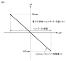
  • FIG. 20 is a diagram showing an example of ⁇ F / ⁇ P characteristics.
  • the horizontal axis of FIG. 20 is the differential power ⁇ P, which is the deviation of the output power of the actual power conversion device 41 with respect to the power target value.
  • the differential power ⁇ P is positive when the output power of the power conversion device 41 is larger than the power target value.
  • the vertical axis of FIG. 20 is the difference frequency ⁇ F, which is the deviation of the frequency of the AC voltage output by the power conversion device 41 with respect to the reference frequency Ref (for example, 60 Hz) of the AC system.
  • the difference frequency ⁇ F is positive when the frequency of the AC voltage output by the power conversion device 41 is higher than the reference frequency Fref.
  • ⁇ Fmax is the maximum value of the difference frequency ⁇ F.
  • the ⁇ F / ⁇ P characteristics shown in FIG. 20 are the capacity and speed adjustment factor Kgd of the static inverter (second DC / AC converter 408). And the braking coefficient Dg.
  • the charge of the storage battery 40 is not considered, and the power target value is set to half the capacity of the static inverter (second DC / AC converter 408).
  • the system frequency when the power consumption of the load 600 in FIG. 2 becomes the same as the capacity of the static inverter (second DC / AC converter 408) is set as the upper limit value (Fref + ⁇ Fmax), and the load 600 is consumed.
  • the ⁇ F / ⁇ P characteristics when the system frequency when the power becomes zero is set to the lower limit value (Ref ⁇ Fmax) are shown.
  • the ⁇ F / ⁇ P characteristic shown in FIG. 20 is referred to as “reference ⁇ F / ⁇ P characteristic”.
  • reference ⁇ F / ⁇ P characteristic in the discharge mode of the storage battery 40, half of the capacity of the static inverter is set as the power target value, and when the output of the static inverter matches the capacity, the system frequency is the upper limit value ( (Fref + ⁇ Fmax), which is the ⁇ F / ⁇ P characteristic under the condition that the system frequency becomes the lower limit value (Ref ⁇ Fmax) when the output of the static inverter becomes zero.
  • the details of the discharge mode will be described later.
  • FIG. 21 is a diagram showing a response waveform of the frequency of the AC voltage output from the static inverter when the load is suddenly changed in the virtual synchronous generator control mounted on the power conversion device 41 according to the first embodiment. ..
  • the virtual synchronous generator control mounted on the static inverter covers minute vibrations and short-period fluctuations of about several tens of meters to several minutes. Therefore, the response performance of 1 second or less is required for the virtual synchronous generator control.
  • the time constant is made small, the response performance is improved, but vibration occurs in the response waveform.
  • problems such as unnecessary cross current may occur. Therefore, in the first embodiment, as shown in FIG. 21, the time constants in the governor control circuit 833 (FIG. 15) and the mass point system arithmetic circuit 837 (FIG. 16) are determined so that the system frequency converges in about 1 second. ..
  • FIG. 22 is a diagram showing the response waveform of the effective value of the AC power output from each of the static inverters of the two power conversion devices 41 equipped with the conventional virtual synchronous generator control.
  • the response waveform shown in FIG. 22 shows the waveform of the effective value of the AC power output from each static inverter when a self-sustaining system is configured by using two power conversion devices 41 and the load is suddenly changed. ..
  • the inverter capacity of each power conversion device 41 is 4 kW, and the power consumption of the load is 3.3 kW.
  • the power target value of the first storage battery (denoted as "BAT1" in the figure) corresponding to the first power conversion device 41 is set to 2.2 kW, and the second storage battery corresponding to the second power conversion device 41 (FIG.
  • the power target value of (denoted as "BAT2”) is set to 1.1 kW, and the first and second power conversion devices 41 are controlled. In such a state, it is assumed that the power consumption of the load suddenly changes to about half (1.65 kW) in about 5 seconds.
  • the power near the power target value (2.2 kW) is output from the first power conversion device 41, and the power target is output from the second power conversion device 41.
  • Power near the value (1.1 kW) is output, and the power ratio between the two is 2: 1.
  • the output power of the first power conversion device 41 is 1.35 kW
  • the output power of the second power conversion device 41 is 0.3 kW
  • the power ratio between the two is 9. : 2.
  • the power is output from the two power conversion devices 41 at a ratio (9: 2) different from the expected power ratio (2: 1). I understand.
  • FIG. 23 shows the response waveform of the frequency of the AC voltage output from each static inverter when two power conversion devices 41 equipped with the conventional virtual synchronous generator control are operated under the above conditions. As shown in FIG. 23, it can be seen that the frequency of the AC voltage converges to almost the same frequency by the virtual synchronous generator control even after the load suddenly changes.
  • FIG. 24 is a diagram showing an example of the ⁇ F / ⁇ P characteristics of the first power conversion device 41 that implements the conventional virtual synchronous generator control.
  • FIG. 25 is a diagram showing an example of the ⁇ F / ⁇ P characteristics of the second power conversion device 41 that implements the conventional virtual synchronous generator control.
  • each power conversion device 41 when the load suddenly changes, the virtual synchronous generator control mounted on each power conversion device 41 operates so that the two power conversion devices 41 share the excess / deficiency power. At this time, as shown in FIG. 23, the two power conversion devices 41 are controlled so that the frequencies of the AC voltages output from the static inverters are equal to each other.
  • the differential power ⁇ P between the power output from each power conversion device 41 and the power target value is determined by the ⁇ F / ⁇ P characteristics shown in FIGS. 24 and 25. Therefore, when the ⁇ F / ⁇ P characteristics of the two power conversion devices 41 are the same, the difference frequency ⁇ F is the same, so that the difference power ⁇ P is also the same value. As a result, as shown in FIG. 22, after the sudden change in the load, the two power conversion devices 41 output power at a ratio different from the expected power ratio.
  • FIG. 26 is a diagram showing an example of ⁇ F / ⁇ P characteristics of the second power conversion device 41 that implements the virtual generator control according to the first embodiment.
  • the solid line in the figure shows the ⁇ F / ⁇ P characteristic of the second power conversion device 41, and the broken line shows the ⁇ F / ⁇ P characteristic of the first power conversion device 41 (FIG. 24).
  • the power target value (1.1 kW) of the second power conversion device 41 is half of the power target value (2.2 kW) of the first power conversion device 41 (that is,).
  • the power split ratio is 2: 1), and as shown in FIG. 26, the differential power ⁇ P ( ⁇ P1 in the figure) of the first power conversion device 41 and the second power conversion device 41 at the same difference frequency ⁇ F.
  • the ⁇ F / ⁇ P characteristic of the second power conversion device 41 is determined so that the ratio with the differential power ⁇ P ( ⁇ P2 in the figure) becomes equal to the ratio of the power target value (2: 1).
  • the ratio of the power shared by each power conversion device 41 is notified from the CEMS 31 even when the load changes. It can be seen that it is equal to the ratio of the power target value (2: 1).
  • the CEMS 31 when the ⁇ F / ⁇ P characteristic of each power conversion device 41 is created, the CEMS 31 first creates the reference ⁇ F / ⁇ P characteristic for each power conversion device 41. In the following description, a method of creating the reference ⁇ F / ⁇ P characteristic will be described only for discharging the storage battery 40.
  • the operation mode of the storage battery 40 includes a discharge mode for discharging the storage battery 40, a charge mode for charging the storage battery 40, and a charge / discharge mode for charging / discharging the storage battery 40.
  • the reference ⁇ F / ⁇ P characteristic is set so that the differential power ⁇ P corresponding to the limit value ⁇ Fmax of the differential frequency ⁇ F is half the capacity of the static inverter. create.
  • the reference ⁇ F so that the differential power ⁇ P corresponding to ⁇ Fmax becomes equal to the capacity of the static inverter. Create the / ⁇ P characteristic.
  • the CEMS 31 needs to create the reference ⁇ F / ⁇ P characteristics of the plurality of power conversion devices 41 to be managed with the same policy. Therefore, the CEMS 31 creates the reference ⁇ F / ⁇ P characteristic in consideration of the charge / discharge mode in the first power conversion device 41, while the reference in consideration of the charge mode or the discharge mode in the second power conversion device 41. No ⁇ F / ⁇ P characteristics are created.
  • FIG. 27 is a diagram showing an example of reference ⁇ F / ⁇ P characteristics in the power conversion device 41 that implements the virtual synchronous generator control according to the first embodiment.
  • the CEMS 31 creates the reference ⁇ F / ⁇ P characteristic based on the information regarding the limit value (Fref ⁇ ⁇ Fmax) of the system frequency and the information regarding the capacity of the static inverter notified from the DSO21.
  • the power target value Pref is set to half the capacity of the static inverter
  • the system frequency is set when the power conversion device 41 outputs power equal to the capacity of the static inverter.
  • the reference ⁇ F / ⁇ P characteristic is created so that the lower limit value (Fref- ⁇ Fmax) is reached and the system frequency becomes the upper limit value (Fref + ⁇ Fmax) when the output of the static inverter becomes zero.
  • the charging power is treated as a negative value
  • the system frequency becomes the lower limit value (Fref- ⁇ Fmax) when the charging power becomes zero
  • the charging power is the capacity of the static inverter.
  • the same effect can be obtained by creating the reference ⁇ F / ⁇ P characteristics so that the system frequency becomes the upper limit value (Fref + ⁇ fmax) when they become equal.
  • the power target value Pref is set to zero, and when discharging power equal to the capacity of the static inverter, the system frequency becomes the lower limit value (Ref- ⁇ Fmax), and the capacity of the static inverter.
  • the same effect can be obtained by creating the reference ⁇ F / ⁇ P characteristic so that the system frequency becomes the upper limit value (Fref + ⁇ Fmax) when charging the electric power equal to the above.
  • the reference ⁇ F / ⁇ P characteristic shown in FIG. 27 is used to create a ⁇ F / ⁇ P characteristic when the power target value is different from the power target value (half of the static inverter capacity) in the reference ⁇ F / ⁇ P characteristic.
  • the broken line in the figure shows the reference ⁇ F / ⁇ P characteristic (FIG. 27), and the solid line shows the ⁇ F / ⁇ P characteristic.
  • the power conversion device uses half (0.5 times) of the capacity of the static inverter with respect to the slope of the reference ⁇ F / ⁇ P characteristic (broken line in the figure).
  • the slope of the ⁇ F / ⁇ P characteristic (solid line in the figure) is obtained by multiplying the result of division by the power target value Pref of 41.
  • Pref the power target value
  • the standard static inverter capacity is determined in advance. For example, when the capacities of the three static inverters are 10 kW, 8 kW, and 4 kW, 8 kW is used as a reference. Needless to say, there is basically no problem in selecting based on any capacity. Then, the reference ⁇ F / ⁇ P characteristic of the static inverter having the reference capacitance (8 kW) is created by using the creation method described in FIG. 27.
  • FIG. 29 is a diagram for explaining a method of creating a reference ⁇ F / ⁇ P characteristic of a static inverter having a capacity of 4 kW.
  • the broken line in the figure shows the reference ⁇ F / ⁇ P characteristic of the static inverter having a reference capacitance (FIG. 27), and the solid line shows the reference ⁇ F / ⁇ P characteristic of the static inverter having a capacitance of 4 kW.
  • the slope of the reference ⁇ F / ⁇ P characteristic with respect to the reference capacitance (8 kW) is multiplied by the value obtained by dividing the reference capacitance (8 kW this time) by the capacity of the own static inverter (4 kW this time).
  • the slope of the reference ⁇ F / ⁇ P characteristic is obtained.
  • FIG. 30 is a diagram showing an example of reference ⁇ F / ⁇ P characteristics and ⁇ F / ⁇ P characteristics of two power conversion devices 41 having different capacities of a static inverter.
  • the broken line L1 shows the reference ⁇ F / ⁇ P characteristic of the first power conversion device 41
  • the solid line L2 shows the ⁇ F / ⁇ P characteristic of the first power conversion device 41.
  • the broken line L3 shows the reference ⁇ F / ⁇ P characteristic of the second power conversion device 41
  • the solid line L4 shows the ⁇ F / ⁇ P characteristic of the second power conversion device 41.
  • the capacity of the static inverter is 8 kW, and the power target value is 6 kW.
  • the capacity of the static inverter is 4 kW, and the power target value is 1 kW.
  • FIG. 31 is a diagram showing waveforms of effective values of AC power output from the two power conversion devices 41 shown in FIG. 30.
  • the waveform of FIG. 31 is a control parameter (Tg,) generated by the virtual synchronous generator control circuit 83 based on the ⁇ F / ⁇ P characteristics (solid lines L2 and L4 in the figure) of the two power conversion devices 41 shown in FIG. Kgd, M and Dg) are used to operate the first and second power conversion devices 41.
  • FIG. 31 shows the waveform of the effective value of the AC power output from each power conversion device 41 when the load suddenly changes from 3 kW to 5.25 kW.
  • the power split ratio of the first and second power conversion devices 41 is 2: 1 both before the load suddenly changes and after the load suddenly changes, which is as expected. You can see that it is working.
  • the ratio of the power output from each power conversion device 41 is the power target value notified from the CEMS 31.
  • the reference ⁇ F / ⁇ P characteristic of each power conversion device 41 is created, and the created reference ⁇ F / ⁇ P characteristic is used according to the power target value.
  • the method of creating the / ⁇ P characteristic has been described, but the present invention is not limited to this.
  • the control parameters (Tg, Kgd, M, Dg) of the virtual synchronous generator control circuit 83 may be directly generated based on the capacity of the static inverter, the power target value, and the SOC information of the storage battery 40. good.
  • the distribution system 24 has the substation 20 and the power conversion device 27 (or the power conversion device 41a or the town 100a) in order to control the system voltage supplied from the substation 20 within a predetermined voltage range. ), And a plurality of SVRs 23 are connected in series.
  • the power conversion device 27 operates as a current source.
  • a power conversion device 41a is installed near the power conversion device 27. In the first embodiment, the power conversion device 41a operates as a voltage source.
  • the power conversion device 41a can also smooth the generated power of the mega solar 26 by executing the virtual synchronous generator control.
  • the load includes towns 100a to 100d, factories 110, buildings 112, and condominiums 113.
  • the power supplied from the substation 20, the generated power of the mega solar 26, and the discharge power of the storage battery 40 are supplied to the load.
  • An emergency synchronous generator is installed in the factory, and an emergency synchronous generator is installed in the building.
  • FIG. 32 is a sequence diagram for explaining the normal operation of the distributed power supply system centered on the CEMS 31 shown in FIG. 1.
  • the steady-state processing includes a processing performed in a 30-minute cycle (hereinafter, also referred to as “first processing”) and a processing performed in a 5-minute cycle (hereinafter, “second processing”). It is also called “processing”).
  • the DSO 21 requests the CEMS 31 to output the collected measurement data via the communication line 25.
  • the CEMS 31 collects measurement data including the power consumption of each consumer, the power generation amount of the mega solar 26, the charge / discharge power amount of the storage battery 40, and the SOC collected in the last 30 minutes. Send to.
  • the DSO 21 Upon receiving the measurement data, the DSO 21 creates an operation plan for the distribution system 24 based on the measurement data, and notifies the CEMS 31 of the created operation plan.
  • the operation plan of the distribution system 24 includes the power supply plan from the substation 20 to the distribution system 24, and is necessary for creating the operation plan (charge / discharge plan) of the storage battery 40.
  • DSO21 creates a power supply plan with a 30-minute cycle for 24 hours.
  • the 30-minute cycle power supply plan shows the total amount of power supplied from the substation 20 to the distribution system 24 in 30 minutes.
  • the CEMS 31 When the CEMS 31 receives the operation plan (power supply plan) from the DSO21, it requests the power conversion device 41 to transmit the measurement data.
  • the measurement data includes the charge / discharge power amount and SOC information of the storage battery 40 for the last 5 minutes.
  • the power conversion device 41 Upon receiving the request from the CEMS 31, the power conversion device 41 notifies the CEMS 31 of the measurement data.
  • the CEMS 31 receives measurement data from all the power conversion devices 41a to 41c connected to the distribution system 24. At this time, the CEMS 31 also collects measurement data such as the power consumption of each consumer for 30 minutes and the power generation amount of the mega solar 26.
  • the operation plan of the storage battery 40 is a charge / discharge plan of the storage battery 40, and includes a target value (power target value) of the charge / discharge power of the storage battery 40.
  • the operation plan of the storage battery 40 and the method of creating control parameters will be described later.
  • the CEMS 31 When the creation of the operation plan and control parameters of the storage battery 40 is completed, the CEMS 31 notifies each power conversion device 41 of the operation plan and control parameters of the corresponding storage battery 40, and ends the first process.
  • CEMS 31 carries out a second process (5-minute cycle process).
  • the CEMS 31 collects measurement data from each power conversion device 41 in a 5-minute cycle.
  • the CEMS 31 detects the deviation between the power target value and the actual charge / discharge power based on the collected measurement data.
  • the CEMS 31 recalculates the operation plan (power target value) of the storage battery 40 and notifies each power conversion device 41 of the recalculation result.
  • the specific recalculation method will be described later.
  • FIG. 33 is a flowchart showing the control process of CEMS 31 shown in FIG.
  • the CEMS 31 confirms in step (hereinafter, abbreviated as S) 01 whether or not the output request of the measurement data from the DSO 21 has been received.
  • S step
  • the CEMS 31 collects measurement data from a plurality of power conversion devices 41 by S02.
  • the CEMS 31 notifies the DSO 21 of the measurement data stored in the storage circuit 12 by the S03 via the communication circuit 11.
  • the CEMS 31 proceeds to S04 and the operation plan (power supply plan) is performed from the DSO21. Check if you have received.
  • the operation plan is received (YES in S04)
  • the CEMS 31 proceeds to S05 and creates an operation plan (charge / discharge plan) for the storage battery 40.
  • FIG. 34 is a flowchart showing a process of creating an operation plan for the storage battery 40 (S05 in FIG. 33).
  • the CEMS 31 predicts the power generation amount of the mega solar 26 by S051.
  • the control circuit 16 (FIG. 3) with respect to the second management circuit 146 (FIG. 4) in the operation plan creation circuit 14. , Instruct to make an operation plan.
  • the second management circuit 146 instructs the power generation power generation prediction circuit 142 to predict the power generation power of the mega solar 26 via the storage battery operation plan creation circuit 141.
  • the generated power prediction circuit 142 Upon receiving an instruction from the second management circuit 146, the generated power prediction circuit 142 accesses a weather forecast server located on the Internet (not shown) to forecast the weather for 24 hours from the present to 24 hours later. To get.
  • the power generation power prediction circuit 142 uses the acquired weather forecast for 24 hours and the data stored in the database for power generation amount prediction (not shown) managed by the power generation power prediction circuit 142, and is 24 from the present. Predict the amount of power generated for 24 hours until after hours.
  • the database for predicting the amount of power generation is constructed based on the actual amount of power generated by the mega solar 26 and the weather actual information collected every 30 minutes. The description of how to build the database is omitted.
  • CEMS31 predicts the power consumption of the consumer by S052. Specifically, returning to FIG. 4, when the second management circuit 146 receives the prediction result of the power generation amount of the mega solar 26 from the power generation power prediction circuit 142, the second management circuit 146 goes through the storage battery operation plan creation circuit 141. The power consumption prediction circuit 143 is instructed to predict the power consumption of the consumer.
  • the power consumption prediction circuit 143 Upon receiving an instruction from the second management circuit 146, the power consumption prediction circuit 143 currently uses the data stored in the power consumption prediction database (not shown) managed by the power consumption prediction circuit 143. Predict the power consumption of consumers for 24 hours from to 24 hours later.
  • the database for power consumption forecast is constructed by processing the power consumption of the consumer collected in a 30-minute cycle based on the date, time information, and weather information. The description of how to build the database is omitted.
  • CEMS31 Predicting the power consumption of the consumer in S052, CEMS31 creates a demand plan in S053. Specifically, returning to FIG. 4, when the prediction result of the power consumption of the consumer is received from the power consumption prediction circuit 143, the storage battery operation plan creation circuit 141 is the power generation power of the mega solar 26 by the power generation power prediction circuit 142. Based on the quantity prediction result, the consumer power consumption prediction result by the power consumption prediction circuit 143, and the operation plan (power supply plan every 30 minutes) notified from DSO21, every 30 minutes of the storage batteries 40a to 40c. Calculate the total value of charge / discharge power.
  • CEMS31 formulates the charge / discharge power (power target value) of the storage batteries 40a to 40c by S054.
  • each storage battery operation plan creation circuit 141 is based on the SOC information and the storage battery capacity of the storage batteries 40a to 40c collected in the storage circuit 12 via the communication circuit 11.
  • the charge / discharge power of the storage battery 40 every 30 minutes is divided into proportions.
  • the CEMS 31 when the operation plan of the storage battery 40 for 24 hours is created, the CEMS 31 is almost the same when the SOCs of the storage batteries 40a to 40c become zero at the same time or when the storage batteries 40a to 40c are in the charging mode.
  • the charge / discharge power of each storage battery 40 is determined so that the battery is fully charged at the same time.
  • the generated power of the mega solar 26 drops from 10 MW to 4 MW for about 5 minutes due to a cloud crossing above the mega solar 26.
  • the capacities of the static inverters of the power converters 41a to 41c are 8 MW, 4 MW, and 2 MW, respectively.
  • the SOC of the storage battery 40a first becomes zero and the discharge is stopped, so that 1 MW and 0.5 MW are discharged from the remaining storage batteries 40b and 40c, respectively, so that the storage battery is operated with respect to the power conversion devices 41b and 41c.
  • the plan has been notified.
  • the generated power of the mega solar 26 decreases by 6 MW due to a sudden change in the amount of solar radiation
  • the discharge power of the storage batteries 40b and 40c is insufficient because only 3 MW and 1.5 MW can be additionally output by the virtual synchronous generator control, respectively. It is not possible to compensate for 6 MW.
  • the CEMS 31 When the charge / discharge power (power target value) of the storage batteries 40a to 40c was determined in S054, the CEMS 31 generated the information necessary for generating the control parameters for the virtual generator control for all the storage batteries 40a to 40c by S055. Check if. When the generation of information for all the storage batteries 40a to 40c has not been completed (NO in S055), the CEMS 31 proceeds to S056 and generates the information necessary for generating the control parameters for the virtual generator control.
  • FIG. 35 is a flowchart showing a process (S056 in FIG. 34) for generating information necessary for generating control parameters for virtual synchronous generator control.
  • the process shown in FIG. 35 is executed by the control parameter generation circuit 13 (FIG. 5) in the CEMS 31.
  • the control circuit 136 (FIG. 5) is generated by the storage battery operation plan creation circuit 141 in S054 of FIG. 34 by S0561, and the storage battery 40 for the next 30 minutes.
  • Information about the power target value of the power conversion device 41, the capacity of the second DC / AC converter 408 (static inverter) in the power conversion device 41, and the distribution system 24 is collected.
  • the information regarding the distribution system 24 includes the upper limit value and the lower limit value of the system frequency, the response performance of the virtual synchronous generator control circuit 83 (FIG. 11), and the like.
  • the upper limit of the system frequency is the reference frequency Ref (for example, 60 Hz) + ⁇ Fmax, and the lower limit of the system frequency is Ref ⁇ Fmax.
  • the reference ⁇ F / ⁇ P characteristic calculation circuit 131 calculates the reference ⁇ F / ⁇ P characteristic for each power conversion device 41 according to S0562.
  • the reference ⁇ F / ⁇ P characteristics will be described.
  • the control parameters of the power converter 41 equipped with the virtual synchronous generator control first, the reference ⁇ F / ⁇ P characteristics of the static inverter are calculated.
  • the configuration for generating the control parameter for the power conversion device 41 will be described, but the configuration in which the virtual synchronous generator control is implemented in the power conversion device whose output can be adjusted, such as the wind power generation device, is also described.
  • the control parameters can be generated using the same method.
  • the reference ⁇ F / ⁇ P characteristic calculation circuit 131 sets half of the capacity of the static inverter as the power target value in the discharge mode of the storage battery 40, and the static inverter has a power target value.
  • FIG. 36 is a flowchart showing a process (S0562 in FIG. 35) for generating a reference ⁇ F / ⁇ P characteristic.
  • the reference ⁇ F / ⁇ P characteristic calculation circuit 131 collects the capacitance information (Cinv) of the target static inverter from the control circuit 136 according to S05621.
  • the reference ⁇ F / ⁇ P characteristic calculation circuit 131 collects the system information ( ⁇ Fmax) according to S05622. Next, the reference ⁇ F / ⁇ P characteristic calculation circuit 131 obtains the slope of the reference ⁇ F / ⁇ P characteristic by using the inverter capacitance Cinv and ⁇ Fmax according to S05623.
  • the reference ⁇ F / ⁇ P characteristic calculation circuit 131 sets the slope of the reference ⁇ F / ⁇ P characteristic to ⁇ Fmax / (Cinv ⁇ 0.5).
  • the slope of the reference ⁇ F / ⁇ P characteristic is set to ⁇ Fmax / Cinv.
  • the storage battery operation plan creation circuit 141 determines. Specifically, when the determined absolute value of the charge / discharge power is less than a predetermined value, the storage battery operation plan creation circuit 141 adopts the charge / discharge mode. The adopted mode is applied to all the power conversion devices 41 connected to the distribution system 24.
  • the ⁇ F / ⁇ P characteristic calculation circuit 132 (FIG. 5) generates the ⁇ F / ⁇ P characteristic according to S0563. Specifically, the reference ⁇ F / ⁇ P characteristic calculation circuit 131 outputs the slope of the generated reference ⁇ F / ⁇ P characteristic to the control circuit 136 and the ⁇ F / ⁇ P characteristic calculation circuit 132.
  • the ⁇ F / ⁇ P characteristic calculation circuit 132 calculates the ⁇ F / ⁇ P characteristic based on the power target value given by the control circuit 136.
  • FIG. 37 is a flowchart showing a process for generating ⁇ F / ⁇ P characteristics (S0563 in FIG. 35). As shown in FIG. 37, when the process is started, the ⁇ F / ⁇ P characteristic calculation circuit 132 collects the power target value Pref from the control circuit 136 by S05631. The ⁇ F / ⁇ P characteristic calculation circuit 132 determines, according to S05632, whether or not the magnitude of the collected power target value Pref exceeds the static inverter capacity Cinv.
  • the ⁇ F / ⁇ P characteristic calculation circuit 132 sets the power target value Pref by the limiter in S05633 in the static inverter capacity Cinv. Limit to.
  • the ⁇ F / ⁇ P characteristic calculation circuit 132 obtains the slope of the ⁇ F / ⁇ P characteristic by using the power target value Pref according to S05634. Specifically, when the storage battery 40 is in the discharge mode or the charge mode, the slope of the ⁇ F / ⁇ P characteristic is set to the slope of the reference ⁇ F / ⁇ P characteristic ⁇ (Cinv ⁇ 0.5) / Ref. On the other hand, when the storage battery 40 is in the charge / discharge mode, it is assumed that it absorbs fluctuations in the generated power of renewable energy such as mega solar 26 or wind power generation (power target value is zero), and only the static inverter capacity is used.
  • renewable energy such as mega solar 26 or wind power generation
  • the ⁇ F / ⁇ P characteristic depending on the above, that is, the reference ⁇ F / ⁇ P characteristic obtained in S0562 of FIG. 35 is used as it is.
  • the slope of the ⁇ F / ⁇ P characteristic, the system information ( ⁇ ⁇ Fmax, etc.), and the power target value Pref are used as the information necessary for generating the control parameters of the virtual synchronous generator control will be described.
  • the control parameter generation circuit 13 is necessary for generating control parameters for all the power conversion devices 41 connected to the distribution system 24. Check if the calculation of information is completed. When the calculation of the information for all the power conversion devices 41 is not completed (NO in S055), the information necessary for generating the control parameter of the next power conversion device 41 is calculated. When the calculation of the information is completed for all the power conversion devices 41 (YES in S055), the control parameter generation circuit 13 ends the process of creating the operation plan of the storage battery 40 (S05 in FIG. 33).
  • the storage battery operation plan creation circuit 141 (FIG. 4) transmits the created operation plan (power target value) via the second management circuit 146. Notify the first management circuit 145 (FIG. 4).
  • the first management circuit 145 receives the operation plan, the first management circuit 145 stores the received operation plan in the memory and notifies the transmission data generation circuit 15 (FIG. 3).
  • the control parameter generation circuit 13 notifies the transmission data generation circuit 15 of the generated information.
  • the transmission data generation circuit 15 acquires the operation plan (power target value) of the storage battery 40 and the information necessary for generating the control parameters, it processes these into a transmission format and outputs them to the communication circuit 11 (FIG. 3). ..
  • the communication circuit 11 receives the transmission data from the transmission data generation circuit 15, the communication circuit 11 transmits the transmission data to the corresponding power conversion device 41 via the communication line 25.
  • CEMS31 proceeds to S06 and has the collection time of various measurement data arrived? To confirm.
  • the CEMS 31 collects measurement data at 5-minute intervals. If the collection time of the measurement data has not arrived (NO in S06), the process returns to S01.
  • the CEMS 31 collects the measurement data in S07. In the first embodiment, the CEMS 31 collects the charge / discharge power amount, the current charge / discharge power, and the SOC information of the storage battery 40 for 5 minutes from each of the power conversion devices 41a to 41c as measurement data.
  • the CEMS 31 confirms whether or not the operation plan of the storage battery 40 needs to be revised by S08.
  • the CEMS 31 compares the current charge / discharge power with the operation plan (power target value) for each of the plurality of storage batteries 40. Specifically, the CEMS 31 confirms whether the power difference between the current charge / discharge power and the power target value exceeds a predetermined range, and whether the SOC of the storage battery 40 exceeds a predetermined allowable range. .. If the power difference in any one of the plurality of storage batteries 40 exceeds a predetermined range and / or the SOC exceeds an allowable range, the CEMS 31 determines the operation plan of all the storage batteries 40. Review. The operation plan of the storage battery 40 in which the power difference exceeds a predetermined range and / or the SOC exceeds an allowable range may be reviewed.
  • the CEMS 31 confirms whether the operation plan of the storage battery 40 needs to be revised in the above manner, and if it is determined that the operation plan of the storage battery 40 does not need to be revised (NO in S08), the CEMS 31 returns to S01 and continues the process. On the other hand, when it is determined that the operation plan of the storage battery 40 needs to be revised (YES in S08), the CEMS 31 proceeds to S09 and corrects the operation plans of all the storage batteries 40.
  • FIG. 38 is a flowchart showing a process (S09 in FIG. 33) for modifying the operation plan of the storage battery 40.
  • the process shown in FIG. 38 is executed by the operation plan creation circuit 14 (FIG. 3) in the CEMS 31.
  • the second management circuit 146 instructs the storage battery operation plan correction circuit 144 (FIG. 4) to revise the operation plan by S091. ,
  • the charge / discharge power and SOC information collected from each power conversion device 41 are transferred.
  • the second management circuit 146 has the operation plan (power target value) of the storage battery 40 stored in the first management circuit 145 (FIG. 4) and the storage circuit 12 with respect to the storage battery operation plan correction circuit 144.
  • the capacity of the static inverter of the power conversion device 41 stored in is also output.
  • the storage battery operation plan correction circuit 144 reviews the operation plan of the storage battery 40 based on the information given from the second management circuit 146.
  • the output power of the power conversion device 41 is twice the power target value because either the predicted value of the power generation amount of the mega solar 26 or the predicted value of the power consumption of each consumer deviates from the actual value. Imagine that it is.
  • the storage battery operation plan correction circuit 144 of the storage battery 40 is based on the measurement data collected in a 5-minute cycle. Revise the operation plan (power target value). Specifically, the storage battery operation plan correction circuit 144 corrects the operation plan of the storage battery 40 based on the current charge / discharge power and SOC information.
  • the reason why SOC is used for modifying the operation plan of the storage battery 40 is that when a lithium ion battery is used as the storage battery 40, the storage battery 40 may fail or deteriorate rapidly due to overcharging or overdischarging. Therefore, in the control of a normal storage battery, when the SOC exceeds, for example, 90%, the charging mode of the storage battery is switched from the constant current charging mode to the constant voltage charging mode. In the constant voltage charging mode, the charging power cannot be increased, so that it is necessary to reduce the power target value in the virtual synchronous generator control. Similarly, even in the case of over-discharging, the storage battery 40 deteriorates, so it is necessary to reduce the discharge power when the SOC falls below, for example, 5%. Therefore, the SOC is used to create and modify the operation plan of the storage battery 40.
  • the storage battery 40 When a lead-acid battery is used as the storage battery 40, it is resistant to overcharging, but tends to deteriorate due to overdischarging. Therefore, in the case of a lead-acid battery, for example, it is necessary to reduce the discharge power when the SOC falls below 20%. As described above, in order to suppress the progress of deterioration of the storage battery used, the SOC is used to correct the power target value.
  • the storage battery operation plan correction circuit 144 creates an operation plan for the storage battery 40 based on the current charge / discharge power, but charging when the SOC is near the upper limit value and the SOC is near the lower limit value. In discharging, an operation plan of the storage battery 40 is created based on the current charge / discharge power and SOC. Specifically, when the SOC is close to the upper limit value, the charge power target value is narrowed down, and when the SOC is close to the lower limit value, the discharge power target value is narrowed down.
  • the control parameter generation circuit 13 When the operation plan (power target value) of the storage battery 40 is modified in S093, has the control parameter generation circuit 13 (FIG. 3) completed the calculation of the information necessary for generating the control parameters for all the storage batteries 40 by S094? To confirm. If the calculation of the information necessary for generating the control parameters for all the storage batteries 40 is completed (YES in S094), the storage battery operation plan correction circuit 144 ends the correction process of the operation plan of the storage battery 40. On the other hand, if the modification of the operation plans of all the storage batteries 40 is not completed (NO in S094), the control parameter generation circuit 13 generates the information necessary for generating the control parameters of the virtual synchronous generator control by S095. do. The method of generating the information required for the control parameters of the virtual synchronous generator control is the same as the method of generating the operation plan of the storage battery 40 described above (S056 and FIG. 35 in FIG. 34). Omit.
  • the process returns to S094, and the control parameter generation circuit 13 confirms whether or not the calculation of the information necessary for generating the control parameters of all the power conversion devices 41 is completed. do.
  • the control parameter generation circuit 13 is set to the control parameter of the next power conversion device 41. Generate the information required for generation.
  • the storage battery operation plan correction circuit 144 corrects the operation plan of the storage battery 40 in S096. finish.
  • the storage battery operation plan creation circuit 141 uses the modified operation plan (power target value) as the second management circuit, as in the case of creating the operation plan. Notify the first management circuit 145 via 146.
  • the first management circuit 145 When the first management circuit 145 acquires the operation plan of the storage battery 40 from the storage battery operation plan creation circuit 141, the first management circuit 145 stores the acquired operation plan in a memory (not shown) and notifies the transmission data generation circuit 15. Similarly, the control parameter generation circuit 13 notifies the transmission data generation circuit 15 of the information necessary for the operation plan of the storage battery 40 and the generation of the control parameters.
  • the transmission data generation circuit 15 When the transmission data generation circuit 15 receives information necessary for generating the operation plan and control parameters of the storage battery 40, it processes these into a transmission format and outputs them to the communication circuit 11.
  • the communication circuit 11 When the communication circuit 11 receives the transmission data from the transmission data generation circuit 15, the communication circuit 11 transmits the transmission data to the corresponding power conversion device 41 via the communication line 25 (S10 in FIG. 33).
  • the capacity and the power target value of the static inverter of each power conversion device 41 are set. Based on this, the information required for the control parameters of the virtual synchronous generator control mounted on the stationary inverter is generated. According to this, even if the power consumption of the load 600 or the generated power of the energy-creating device such as the mega solar 26 fluctuates during the period until the next operation plan is notified from CEMS 31, the operation plan of the storage battery 40 (electric power). The excess and deficiency power can be shared by the same ratio as the target value).
  • the generated power of the mega solar 26 is reduced by 50% due to a change in the amount of solar radiation immediately after notifying all the power conversion devices 41 of the operation plan, the insufficient 50% of the power is created in the operation plan. It is prorated based on the ratio of the power target value calculated at times. For example, when the charge / discharge power of each storage battery 40 is set so that the SOC of all the storage batteries 40 becomes zero at almost the same time when the power target value is controlled according to the ratio at the time of creating the operation plan. Even if the generated power of the mega solar 26 is reduced by 50%, the excess and deficiency power is divided based on the ratio of the power target values, so the SOC of all the storage batteries 40 should be controlled to be zero at almost the same time. Can be done.
  • the inverter capacity and the power target value are used for calculation.
  • the configuration has been described, but the present invention is not limited to this.
  • the capacity of the storage battery 40a is doubled with respect to the inverter capacity of the power conversion device 41a, and the capacity of the storage battery 40b is tripled with respect to the inverter capacity of the power conversion device 41b.
  • an operation plan (power target value) of each storage battery 40 is generated in consideration of the capacity ratio.
  • the same effect can be obtained by considering the capacity ratio when generating the control parameter.
  • the first control circuit 204 monitors the DC voltage measured by the voltmeter 201.
  • the first control circuit 204 shifts the power conversion device 27 from the standby state to the normal operation when the DC voltage exceeds a predetermined voltage value.
  • the second control circuit 209 in the power converter 27 controls the first DC / AC converter 208.
  • the control of the power conversion device 27 during normal operation will be described.
  • the first control circuit 204 confirms whether the mega solar 26 is generating power. Specifically, the first control circuit 204 confirms whether the output voltage of the mega solar 26 measured by the voltmeter 201 exceeds a predetermined voltage. When the output voltage exceeds a predetermined voltage, the first control circuit 204 notifies the second control circuit 209 that the mega solar 26 can generate electricity.
  • the second control circuit 209 When the second control circuit 209 receives the notification from the first control circuit 204, power is supplied from the substation 20 to the distribution system 24 based on the AC voltage of the distribution system 24 measured by the voltmeter 10. Check if it is (whether the distribution system 24 is out of power).
  • the second control circuit 209 starts the DC / AC converter 208 and also activates the DC / AC converter 208. , Instruct the first control circuit 204 to start the power generation of the mega solar 26.
  • the DC bus voltage of the DC bus 205 is managed by the first DC / AC converter 208 during normal operation will be described. Further, in the first embodiment, the power regenerated from the power conversion device 27 to the distribution system 24 is managed by the current control by the first DC / AC converter 208 to operate the entire distributed power supply management device. And.
  • the fifth control circuit 54 (FIG. 8) of the first control circuit 204 is a mega with respect to the MPPT control circuit 51 (FIG. 8). Instruct to start the maximum power point tracking control of the solar 26.
  • maximum power point tracking control it is managed whether the previous command value is larger or smaller than the previous command value. Then, the generated power of the mega solar 26 measured this time is compared with the generated power of the mega solar 26 measured last time, and if the generated power is increasing, it is in the same direction as the previous time (increase direction or decrease direction). Change the command value.
  • the current command value is increased.
  • the previous command value is smaller than the previous command value
  • the current command value is reduced.
  • the current command value is increased.
  • the first DC / DC converter 203 operates the built-in booster circuit according to the command value output from the first control circuit 204 to generate the first DC voltage output from the mega solar 26. , Converted to a second DC voltage (DC bus voltage of DC bus 205) and output.
  • the second control circuit 209 controls the first DC / AC converter 208 to control the distribution system 24. Outputs (regenerates) the generated power of the mega solar 26. Specifically, the DC bus voltage of the DC bus 205 is monitored, and when the DC bus voltage exceeds the control target value, the generated power is output in synchronization with the AC voltage supplied from the distribution system 24. ..
  • the phase detection circuit 61 detects the zero crossing point of the waveform of the AC voltage of the distribution system 24 measured by the voltmeter 210 (FIG. 1).
  • the first sine wave generation circuit 62 synchronizes with the AC voltage waveform of the distribution system 24 based on the information indicating the zero cross point detected by the phase detection circuit 61 and the AC voltage waveform measured by the voltmeter 210. Generates a reference sine wave. The first sine wave generation circuit 62 outputs the generated reference sine wave to the multiplier 65.
  • the voltmeter 206 measures the voltage of the DC bus 205 and outputs the measured value to the subtractor 63 in the current control circuit 60 and the sixth control circuit 67.
  • the current control circuit 60 uses a control method (current control) that outputs electric power in synchronization with the AC system voltage.
  • This control method is a control method for a general power conversion device for photovoltaic power generation installed in a home.
  • the sixth control circuit 67 stores the target voltage of the DC bus 205, and outputs the target voltage to the subtractor 63.
  • the current control circuit 60 controls the current output by the first DC / AC converter 208 so that the DC bus voltage measured by the voltmeter 206 becomes the target voltage.
  • the output of the subtractor 63 is input to the first PI control circuit 64.
  • the first PI control circuit 64 performs PI control so that the output of the subtractor 63 becomes zero.
  • the output of the first PI control circuit 64 is input to the multiplier 65 and converted into a current command value by being multiplied by the reference sine wave from the first sine wave generation circuit 62.
  • the current command value output from the multiplier 65 is input to the subtractor 66.
  • the subtractor 66 calculates the deviation between the current command value and the AC current value of the distribution system 24 measured by the ammeter 211, and inputs the calculated deviation to the second PI control circuit 68.
  • the second PI control circuit 68 performs PI control so that the deviation output from the subtractor 66 becomes zero.
  • the first PWM converter 69 generates a command value of the first DC / AC converter 208 by executing PWM control with respect to the output of the second PI control circuit 68.
  • the first DC / AC converter 208 outputs an alternating current according to a command value given by the first PWM converter 69.
  • the first The fifth control circuit 54 in the control circuit 204 of the above switches the control of the mega solar 26 from the MPPT control to the voltage control. Specifically, the fifth control circuit 54 controls the DC voltage output from the mega solar 26 so that the AC voltage (AC effective voltage) measured by the voltmeter 210 falls within a predetermined voltage range. Alternatively, the fifth control circuit 54 controls the output voltage of the mega solar 26 so that the generated power of the mega solar 26 falls within the power range notified from the CEMS 31.
  • the first switching circuit 53 (FIG. 8) switches between the output of the MPPT control circuit 51 and the output of the voltage control circuit 52 according to the switching control signal given from the fifth control circuit 54.
  • the sixth control circuit 67 includes a measurement result regarding the DC bus 205 measured by the voltmeter 206 and the ammeter 207, a measurement result regarding the distribution system 24 measured by the voltmeter 210 and the ammeter 211, and a first control circuit 204.
  • the status information of the first DC / DC converter 203 output from is collected, and the collected information is notified to the CEMS 31 or the like via the communication I / F 212.
  • the sixth control circuit 67 also provides information on the effective voltage of the distribution system 24 measured by the effective voltage measuring unit (not shown) or the active power and the active power of the AC system measured by the effective / reactive power measuring unit (not shown).
  • the CEMS 31 is notified via the communication I / F 212, and the measurement results of the effective voltage, active power, etc. of the AC system are also notified to the fifth control circuit 54.
  • the fifth control circuit 54 suppresses an increase in the AC system voltage by switching the control of the mega solar 26 from MPPT control to voltage control when the effective value of the AC system voltage exceeds a predetermined value. do.
  • the second DC / AC converter 408 since the virtual synchronous generator control is implemented in the power converter 41, the second DC / AC converter 408 operates as a voltage source by executing the voltage control. That is, the third control circuit 404 (FIG. 7) controls so that the voltage of the DC bus 405 becomes a constant value.
  • the operation of the third control circuit 404 will be described with reference to FIG.
  • the voltage of the DC bus 405 is measured by a voltmeter 406.
  • the measured value of the voltmeter 406 is input to the charge control circuit 71, the discharge control circuit 72, and the seventh control circuit 74.
  • the charge control circuit 71 controls the charging power of the storage battery 40 so that the voltage of the DC bus 405 becomes the target voltage when the voltage of the DC bus 405 is larger than the target voltage output from the seventh control circuit 74. ..
  • the discharge control circuit 72 increases the discharge power of the storage battery 40.
  • the output of the charge control circuit 71 and the output of the discharge control circuit 72 are switched by the second switching circuit 73.
  • the seventh control circuit 74 outputs a switching control signal to the second switching circuit 73 based on the voltage value of the DC bus 405 measured by the voltmeter 406.
  • FIG. 39 is a flowchart for explaining the operation of the power conversion device 41.
  • the fourth control circuit 409 initializes various control parameters by S200. Subsequently, according to S201, the fourth control circuit 409 collects the voltage value measured by the voltmeters 401, 406, 410, the current value measured by the ammeter 402, 407, 411, and the status information of the storage battery 40. Since the measured value of the voltmeter 410 is an AC voltage, the effective value of the AC voltage is calculated in the eighth control circuit 87 (FIG. 11), and the effective value is used as the voltage value. Since the measured value of the ammeter 411 is an alternating current, the effective value of the alternating current is calculated in the eighth control circuit 87, and the effective value is used as the current value.
  • the charge / discharge power calculation circuit (not shown) in the seventh control circuit 74 calculates the charge / discharge power and the charge / discharge power amount of the storage battery based on the collected data.
  • the AC voltage of the distribution system 24 measured by the voltmeter 410 is input to the AC frequency detection circuit 81 (FIG. 11).
  • the AC frequency detection circuit 81 detects the zero crossing point of the waveform of the AC voltage by S202.
  • FIG. 12 is a block diagram showing the configuration of the AC frequency detection circuit 81 shown in FIG. As shown in FIG. 12, the measured value of the voltmeter 410 is input to the phase detection circuit 810. According to S202 of FIG. 39, the phase detection circuit 810 detects the zero crossing point of the AC voltage. In the first embodiment, the zero cross point indicates the point and time at which the waveform of the AC voltage measured by the voltmeter 410 switches from negative to positive. The phase detection circuit 810 outputs information indicating the detected zero cross point to the frequency detection circuit 811.
  • the frequency detection circuit 811 calculates the AC voltage cycle based on the time of the zero cross point previously detected by the phase detection circuit 810 and the time of the zero cross point detected this time.
  • the frequency detection circuit 811 calculates the frequency of the AC voltage based on the calculated period.
  • the second sine wave generation circuit 812 outputs the zero cross point information detected by the phase detection circuit 810 and the frequency information of the AC voltage detected by the frequency detection circuit 811 as sine wave information.
  • the zero crossing point information and the frequency information are output to the inverter current control circuit 84, the inverter voltage control circuit 85, the virtual synchronous generator control circuit 83, and the eighth control circuit 87.
  • the phase detection circuit 810 sets the zero cross point detection flag by S203.
  • the fourth control circuit 409 controls the second DC / AC converter 408 by S204.
  • the second DC / AC converter 408 is controlled as a voltage source. That is, the second DC / AC converter 408 is voltage controlled. Therefore, when the power supplied to the distribution system 24 is insufficient, the second DC / AC converter 408 is controlled to increase the output power. On the other hand, when the power supplied to the distribution system 24 becomes excessive, the second DC / AC converter 408 is controlled so as to reduce the output power.
  • FIG. 40 is a flowchart for explaining the details of the control process of the second DC / AC converter 408.
  • the effective power calculation circuit 82 calculates the power value based on the measured values of the voltmeter 410 and the ammeter 411 by S2041, the calculated power value is integrated by S2042. ..
  • the effective power calculation circuit 82 proceeds to S2044 and stores the integrated value of the effective power value for one cycle of the AC voltage in the eighth control circuit 87. It is stored in a circuit (not shown), and the integrated value is initialized to zero by S2045.
  • the inverter voltage control circuit 85 sets the command value of the second DC / AC converter 408 by S2046. Generate.
  • the inverter voltage control circuit 85 has frequency and phase information (input via the second sine wave generation circuit 812) output from the virtual synchronous generator control circuit 83 (FIG. 11), and the first Based on the amplitude information of the AC system voltage input from the control circuit 87 of 8 via the second sine wave generation circuit 812, a control command value for controlling the second DC / AC converter 408 is generated. do.
  • the third sine wave generation circuit 851 has sine wave information (frequency, phase and amplitude information from the AC frequency detection circuit 81, and frequency and phase information calculated by the virtual synchronous generator control circuit 83). ) Is entered.
  • the third sine wave generation circuit 851 generates a target value of the AC system voltage output from the second DC / AC converter 408 based on the input information.
  • the subtractor 852 subtracts the voltage measured by the voltmeter 410 from the output of the third sine wave generation circuit 851, and outputs the subtraction result to the third PI control circuit 853.
  • the third PI control circuit 853 generates a voltage command value by executing PI control for making the input subtraction result zero, and outputs the generated voltage command value to the first current limit circuit 855. ..
  • the first current limiting circuit 855 limits the voltage command value given by the third PI control circuit 853 based on the measurement result of the ammeter 411 input via the eighth control circuit 87. .. For example, consider a case where the power target value notified from the CEMS 31 is 90% of the inverter capacity and the load power consumption increases. In this case, in the ⁇ F / ⁇ P characteristic described in the first embodiment, before the frequency deviation (difference frequency ⁇ F) of the AC system voltage reaches ⁇ Fmax, the output of the power exceeding the inverter capacity in the power conversion device 41 is output. Desired. Therefore, it is necessary to limit the output power (output current) of the power conversion device 41 so as not to exceed the inverter capacity.
  • the current when a current exceeding the current capacity of the second DC / AC converter 408 flows, the current is limited and the current flowing through the second DC / AC converter 408 is a predetermined current. It is controlled to be a value (for example, the current capacity of the second DC / AC converter 408).
  • the first current limiting circuit 855 monitors the current flowing through the second DC / AC converter 408 so that the current does not exceed the current capacity of the second DC / AC converter 408. Control (limit) the value.
  • the output of the first current limiting circuit 855 is input to the second PWM converter 854. It is assumed that the control parameters (control gain and integration time) of the third PI control circuit 853 and the first current limit circuit 855 are output from the eighth control circuit 87.
  • the second PWM converter 854 generates a control command value by executing PWM control using the voltage command value output from the first current limiting circuit 855.
  • the second PWM converter 854 outputs the generated control command value to the second DC / AC converter 408.
  • the virtual synchronous generator control circuit 83 executes the virtual synchronous generator control by S205. ..
  • one cycle of the AC voltage is used as the control cycle.
  • the control cycle may be an integral multiple of one cycle of the AC voltage or a predetermined cycle such as a one-second cycle.
  • FIG. 14 is a block diagram showing the configuration of the virtual synchronous generator control circuit 83.
  • the eighth control circuit 87 determines that the control timing has been reached
  • the eighth control circuit 87 instructs the virtual synchronous generator control circuit 83 to generate information regarding the frequency and phase used for voltage control.
  • the frequency and phase of the sine wave generated by the third sine wave generation circuit 851 (FIG. 13) in the inverter voltage control circuit 85 are updated at the zero cross point. Therefore, in the first embodiment, the control cycle is the cycle of the zero cross point detected by the AC frequency detection circuit 81.
  • FIG. 15 is a block diagram showing a detailed configuration of the governor control circuit 833 shown in FIG.
  • the multiplier 91 multiplies the output of the subtractor 832 (FIG. 14) by the control parameter (-1 / Kgd) notified from the eighth control circuit 87. do.
  • the multiplier 91 inputs the multiplication result to the first-order lag model 92.
  • the speed adjustment rate Kgd and the governor time constant Tg used in the governor control circuit 833 are those notified from the CEMS 31 and those generated by the control parameter generation circuit 88 via the eighth control circuit 87. (Not shown) shall be set and used.
  • the first-order lag system model 92 performs an operation simulating the first-order lag system (1 / (1 + s ⁇ Tg)) using the time constant Tg notified from the eighth control circuit 87, and the calculation result. Is output to the limiter circuit 93.
  • the limiter circuit 93 imposes a limit on the input data. Specifically, the limiter circuit 93 limits the output power of the second DC / AC converter 408 so as not to exceed the power capacity of the second DC / AC converter 408.
  • the adder 835 adds the output of the governor control circuit 833 and the power target value Pref output from the eighth control circuit 87.
  • the power target value Pref the one notified from CEMS 31 is output from the eighth control circuit 87.
  • FIG. 16 is a block diagram showing a detailed configuration of the mass point system arithmetic circuit 837 shown in FIG.
  • the subtractor 101 subtracts the output of the multiplier 103 from the output of the subtractor 836 (FIG. 14), and outputs the subtracted value to the integrator 102.
  • the integrator 102 divides the subtraction result of the subtractor 101 by the inertial constant M output from the eighth control circuit 87, and integrates the division result.
  • the output ⁇ of the integrator 102 corresponds to the difference value with respect to the angular velocity (2 ⁇ ⁇ ⁇ 60 Hz) of the frequency of the AC voltage.
  • the output ⁇ of the integrator 102 is input to the multiplier 103 and the divider 104.
  • the multiplier 103 multiplies the output ⁇ of the integrator 102 by the braking coefficient Dg given by the eighth control circuit 87, and outputs the multiplication result to the subtractor 101.
  • the divider 104 converts ⁇ into a difference value ⁇ f from the reference frequency Fref (60 Hz) by dividing the output ⁇ of the integrator 102 by 2 ⁇ ⁇ .
  • the adder 105 generates a frequency (Fref + ⁇ f) for voltage control in the inverter voltage control circuit 85 (FIG. 11) by adding the output ⁇ f of the divider 104 and the reference frequency Ref (60 Hz).
  • the control parameter generation circuit 88 uses the information necessary for generating the virtual synchronous generator control parameters generated and notified by the CEMS 31.
  • the one generated in is set in a register (not shown) via the eighth control circuit 87, and the one set in the register is used.
  • the frequency information (Fref + ⁇ f) output from the adder 105 is input to the phase calculation circuit 106.
  • the operation of the phase calculation circuit 106 will be described.
  • the frequency information output from the adder 105 (FIG. 16) is integrated by the phase calculation circuit 106 and output as the phase information when the inverter voltage control circuit 85 performs voltage control.
  • the phase information and frequency information output from the quality point system calculation circuit 837 are passed through the second sine wave generation circuit 812 (FIG. 12) in the AC frequency detection circuit 81 and in the inverter voltage control circuit 85. Is input to the third sine wave generation circuit 851 (FIG. 13).
  • the third sine wave generation circuit 851 generates a target value of the AC voltage output from the power conversion device 41 based on the input information.
  • the fourth control circuit 409 confirms whether the measurement data transmission request is received from CEMS 31 by S206.
  • the eighth control circuit 87 (FIG. 11) notifies the CEMS 31 of the measurement data via the communication I / F 412 (FIG. 7) by S207.
  • the eighth control circuit 87 sets the control information reception flag by S209.
  • the eighth control circuit 87 determines whether or not the zero cross point detection flag is set by S210. To confirm. If the zero cross point detection flag is not set (NO in S210), the process returns to S201.
  • the second sine wave generation circuit 812 (FIG. 12) captures the frequency and phase information of the system voltage in S212 by S211. And reset the zero cross point detection flag.
  • the second sine wave generation circuit 812 takes in the frequency and phase information of the system voltage (zero cross point time information in the first embodiment) in S211 by S213. Update to information.
  • the eighth control circuit 87 confirms whether the control information has been received from the CEMS 31 (whether the control information reception flag is set) by S214. If the reception flag is not set (NO in S214), the process is returned to S201.
  • the eighth control circuit 87 receives data of each of the frequency target value (reference frequency Ref) and the power target value Ref by S215. replace.
  • the control parameter generation circuit 88 generates control parameters (speed adjustment rate Kgd, braking coefficient Dg, and inertial constant M) for virtual synchronous generator control by S216.
  • FIG. 41 is a flowchart showing a process of generating control parameters (S216 in FIG. 39).
  • the control parameter generation circuit 88 generates control parameters by using the system information (reference frequency Ref, power target value Ref, ⁇ Fmax information) and the inverter capacity Cinv in addition to the ⁇ F / ⁇ P characteristics.
  • the control parameter generation circuit 88 adjusts the speed by setting each of the speed adjustment rate Kgd and the braking coefficient Dg to predetermined initial values by S2161. Initialize the rate Kgd and the braking coefficient Dg.
  • the control parameter generation circuit 88 proceeds to S2162 and calculates the slope of the ⁇ F / ⁇ P characteristic using the speed adjustment rate Kgd and the braking coefficient Dg.
  • a virtual synchronous generator model that simulates the operation of the virtual synchronous generator control circuit 83 (FIG. 11) is implemented in the control parameter generation circuit 88 (FIG. 11), and the control parameters are set using this model. The case of generating will be described.
  • the method of generating the control parameter is not limited to this, and for example, the relationship between the speed adjustment rate Kgd and the system frequency shown in FIG. 18 is stored as table data corresponding to each braking coefficient Dg, and is also stored.
  • the relationship between the braking coefficient Dg and the system frequency shown in FIG. 19 is stored as table data corresponding to each speed adjustment rate Kgd, and the appropriate speed adjustment rate Kgd and the braking coefficient Dg are used using these table data. May be configured to determine.
  • the virtual synchronous generator model a mathematical model of the block diagram shown in FIGS. 14 to 16 is used, but the present invention is not limited to this.
  • the transfer function of the virtual synchronous generator control circuit 83 (FIG. 11) is generated from the transfer function of the governor control unit shown in the above equation (1) and the sway equation shown in the above equation (2), and the generated transfer function is used. It may be configured to generate control parameters.
  • the control parameter generation circuit 88 When the slope of the ⁇ F / ⁇ P characteristic is calculated in S2162, the control parameter generation circuit 88 has the slope of the ⁇ F / ⁇ P characteristic calculated by S2163 and the ⁇ F / ⁇ P characteristic generated by S0563 (FIG. 37) in FIG. Compare with tilt. Specifically, the control parameter generation circuit 88 confirms whether the deviation of the slopes of these two ⁇ F / ⁇ P characteristics is within a predetermined allowable range.
  • control parameter generation circuit 88 determines that the slopes of the two ⁇ F / ⁇ P characteristics match (YES in S2163), and sets the process to S2169. Proceed.
  • the control parameter generation circuit 88 determines that the slopes of the two ⁇ F / ⁇ P characteristics do not match (NO in S2163). In this case, the control parameter generation circuit 88 proceeds to S2164 and changes the braking coefficient Dg. In the first embodiment, the control parameter generation circuit 88 adds a predetermined value to the current braking coefficient Dg.
  • the control parameter generation circuit 88 confirms by S2165 whether the braking coefficient Dg is within a predetermined range. If the braking coefficient Dg is within the predetermined range (YES in S2165), the control parameter generation circuit 88 returns to S2162 and calculates the slope of the ⁇ F / ⁇ P characteristic using the changed braking coefficient Dg.
  • the control parameter generation circuit 88 determines that appropriate characteristics cannot be obtained with the current speed adjustment rate Kgd, and brakes by S2166.
  • the coefficient Dg is returned to the initial value, and the speed adjustment rate Kgd is changed. Specifically, the control parameter generation circuit 88 adds a predetermined value to the current speed adjustment rate Kgd (initial value).
  • the control parameter generation circuit 88 confirms by S2167 whether the speed adjustment rate Kgd is within a predetermined range.
  • the control parameter generation circuit 88 proceeds to S2168, assuming that an appropriate speed adjustment rate Kgd and a braking coefficient Dg have not been obtained, and speed adjustment.
  • the rate Kgd and the braking coefficient Dg are set to the respective default values prepared in advance, and the process proceeds to S2169.
  • the control parameter generation circuit 88 returns to S2162 and uses the changed speed adjustment rate Kgd and the braking coefficient Dg to ⁇ F /. Calculate the slope of the ⁇ P characteristic.
  • the control parameter generation circuit 88 repeatedly executes the processes of S2162 to S2167 until it is determined to be YES in S2163 or NO is determined in S2167.
  • the braking coefficient Dg and the speed adjustment rate Kgd are calculated from the relationship between the braking coefficient Dg shown in FIG. 19 and the frequency of the AC system voltage.
  • the braking coefficient Dg and the speed adjustment rate Kgd may be calculated from the relationship between the speed adjustment rate Kgd shown in FIG. 18 and the frequency of the AC system voltage.
  • the control parameter generation circuit 88 calculates the inertial constant M by S2169.
  • the inertial constant M is calculated based on the response time required for the virtual synchronous generator control.
  • the response performance of the virtual synchronous generator control is the time constant Tg of the governor control circuit 833 (FIG. 14) and the time constant M / Dg of the mass point system arithmetic circuit 837 (FIG. 14) obtained by the sway equation.
  • Tg the time constant of the governor control circuit 833
  • M / Dg of the mass point system arithmetic circuit 837 (FIG. 14) obtained by the sway equation.
  • the first embodiment since the default value of the governor time constant Tg is used and the governor time constant Tg is not generated, only the time constant of the mass point system calculation circuit 837 is controlled.
  • the time constant of the mass point system calculation circuit 837 is obtained by M / Dg from the above equation (3). Therefore, in the first embodiment, the inertial constant M is calculated by multiplying the braking coefficient Dg by the time constant of the mass point system calculation circuit 837 defined by the default value.
  • control parameter generation circuit 88 notifies the eighth control circuit 87 to that effect. At the same time, the calculated control parameters are output.
  • the eighth control circuit 87 When the eighth control circuit 87 receives the calculated control parameter, the eighth control circuit 87 outputs the control parameter to the virtual synchronous generator control circuit 83 and updates it. When the update of the control parameter is completed, the eighth control circuit 87 clears (reset) the register (not shown) in which the reception flag is set by S217, and returns the process to S201.
  • the operation plans (power target values) of the storage batteries 40a to 40c created by CEMS 31 are notified to the corresponding power conversion devices 41a to 41c, respectively. Even if the demand balance changes significantly immediately afterwards, the ratio of the output powers of the power conversion devices 41a to 41c can be made substantially equal to the ratio of the power target values at the time of creating the operation plan.
  • the operation plan discharge plan
  • the storage batteries 40a to 40c are operated so as to be fully charged almost at the same time.
  • a plan (charge plan) has been created, even if the power consumption of the load 600 or the power generated by the mega solar 26 changes significantly from the assumed power at the time of creating the operation plan, the storage battery 40a will deviate from the assumed time.
  • the SOC of ⁇ 40c can be zeroed almost at the same time, or the storage batteries 40a ⁇ 40c can be fully charged almost at the same time, and the assumed operation plan can be observed.
  • the power conversion device 41 having a relatively small power target value has a high proportion of power.
  • the corresponding storage battery 40 has a SOC of zero prior to the other storage batteries 40.
  • the excess / deficiency power can be prorated to the ratio of the power target value set in the operation plan, so that the SOC is low (that is, the power target value is small). The ratio of the electric power of the storage battery 40 can be kept low.
  • Embodiment 2 a method of generating information necessary for generating control parameters of a virtual synchronous generator control circuit 83 (FIG. 11) mounted on a power conversion device 41, which is executed by CEMS 31, and power conversion.
  • the method of generating the control parameter executed by the control parameter generation circuit 88 (FIG. 11) in the apparatus 41 has been described.
  • the problems of the control parameters generated in the first embodiment and the means for solving the problems will be described.
  • the operation when the information required for generating the control parameter generated by the CEMS 31 is up to the slope of the reference ⁇ F / ⁇ P characteristic will be described.
  • the configuration of the CEMS 31 according to the second embodiment is the same as that of the CEMS 31 according to the first embodiment, and only the processing of the control parameter generation circuit 13 (FIG. 5) and the control parameter generation circuit 88 (FIG. 11) is different. ..
  • the distributed power supply management device according to the second embodiment will be described with a focus on the operation of different parts.
  • 42A and 42B are diagrams for explaining a problem when the power conversion device 41 is controlled according to the control parameters for controlling the virtual synchronous generator described in the first embodiment described above.
  • a power target value corresponding to 12.5% of the inverter capacity is given to the first power conversion device 41 by CEMS 31, and a power target value corresponding to 25% of the inverter capacity is given to the second power conversion device 41. Is given by CEMS31.
  • the horizontal axis of the reference ⁇ F / ⁇ P characteristic and the ⁇ F / ⁇ P characteristic is described as the actual power (kW), but in the following description, the horizontal axis is the charge / discharge output from the power conversion device 41.
  • the power normalized by the inverter capacity of the power conversion device 41 that is, the capacity of the second DC / AC converter 408) is used.
  • the 42A and 42B are reference ⁇ F / ⁇ P characteristics and ⁇ F / ⁇ P characteristics of the power conversion device 41 created under the above conditions.
  • the broken line indicates the reference ⁇ F / ⁇ P characteristic
  • the solid line indicates the ⁇ F / ⁇ P characteristic.
  • FIG. 42A shows the ⁇ F / ⁇ P characteristics of the first power conversion device 41 when the power target value is 12.5% of the inverter capacity.
  • FIG. 42B shows the ⁇ F / ⁇ P characteristics of the second power conversion device 41 when the power target value is 25% of the inverter capacity.
  • the electric power that can be increased by the second power conversion device 41 is up to 25% of the inverter capacity. That is, the power that can be covered by the second power conversion device 41 is up to 50% of the inverter capacity.
  • the power range that can cover the load fluctuation or the fluctuation of the power generation amount becomes narrow.
  • the power fraction when the load fluctuation or the power generation amount fluctuation occurs is obtained in the first embodiment. It is possible to expand the power range that can cover the fluctuation while dividing it into 2: 1 in the same way as above. An example thereof is shown in FIGS. 43A and 43B.
  • FIGS. 43A and 43B illustrate the case where the ⁇ F / ⁇ P characteristic is generated by changing the inclination of the reference ⁇ F / ⁇ P characteristic of each power conversion device 41.
  • the dashed line shows the modified reference ⁇ F / ⁇ P characteristics of the first power converter 41.
  • the dashed line shows the modified reference ⁇ F / ⁇ P characteristics of the second power converter 41.
  • 43A and 43B have a slope of the reference ⁇ F / ⁇ P characteristic that is 1/2 times that of FIGS. 42A and 42B, respectively.
  • the power that can be increased by the first power conversion device 41 by the virtual synchronous generator control is 25% of the inverter capacity.
  • the power increased by the second power conversion device 41 is up to 50% of the inverter capacity. According to this, it becomes possible to cope with double load fluctuations or fluctuations in power generation amount.
  • FIG. 44 is a flowchart for explaining the generation process of the reference ⁇ F / ⁇ P characteristic executed by CEMS31.
  • the information notified to the transmission data generation circuit 15 is information indicating the slope of the reference ⁇ F / ⁇ P characteristic and the reference power command value used when generating the slope. Since the operation of the CEMS 31 other than this is the same as the operation of the CEMS 31 according to the first embodiment, only the generation process of the reference ⁇ F / ⁇ P characteristic will be described below.
  • the reference ⁇ F / ⁇ P characteristic calculation circuit 131 acquires the inverter capacity Cinv_i and the power target value Ref_i of the i-th power conversion device 41 according to S056202.
  • the reference ⁇ F / ⁇ P characteristic calculation circuit 131 compares the inverter capacity Cinv acquired in S056202 with the absolute value of the power target value Def_i.
  • the reference ⁇ F / ⁇ P characteristic calculation circuit 131 changes the power target value Pref_i to the inverter capacity Cinv_i according to S056204.
  • the reference ⁇ F / ⁇ P characteristic calculation circuit 131 uses S056205 to set the power target value.
  • the power target value Pref_i is normalized by the inverter capacity Cinv.
  • the normalized power target value Def_i is referred to as Def_temp.
  • the reference ⁇ F / ⁇ P characteristic calculation circuit 131 compares the absolute value of the normalized power target value Def_temp with the maximum value Def_max of the power target value according to S056206.
  • Def_temp is equal to or greater than Def_max (NO in S056206)
  • Def_max is set to the absolute value of Def_temp.
  • Pcs_no is set to the number i of the current power conversion device 41.
  • the reference ⁇ F / ⁇ P characteristic calculation circuit 131 determines whether the confirmation by S056202 to S056207 for the power conversion devices 41 of all distributed power sources has been completed. In S056209, it is confirmed whether i ⁇ n. If the confirmation of the power converters 41 of all the distributed power sources has not been completed (NO in S05629), the process is returned to S056202.
  • the reference ⁇ F / ⁇ P characteristic calculation circuit 131 determines whether or not Pref_max is less than 0.5 in S056210. Is determined.
  • the reference ⁇ F / ⁇ P characteristic calculation circuit 131 uses the power target value (command value normalized by the inverter capacity) used when generating the reference ⁇ F / ⁇ P characteristic. Is set to 0.5. According to this, the control parameters used in the virtual synchronous generator control circuit 83 are substantially the same as those described in the first embodiment.
  • the reference ⁇ F / ⁇ P characteristic calculation circuit 131 uses S056212 to generate the reference ⁇ F / ⁇ P characteristic, and the power target value (normalized by the inverter capacity) is used.
  • the given command value is set to Ref_max.
  • FIGS. 45A and 45B a method of generating the reference ⁇ F / ⁇ P characteristic and the ⁇ F / ⁇ P characteristic according to the second embodiment will be described with reference to FIGS. 45A and 45B.
  • FIGS. 45A and 45B it is assumed that the first power conversion device 41 and the second power conversion device 41 are connected to the distribution system 24.
  • the command value for generating the reference ⁇ F / ⁇ P characteristic is set to 0.5, when the system frequency drops by ⁇ Fmax, the output power of the power conversion device 41 is the inverter capacity Cinv ⁇ 0. It becomes 5.
  • the command value when generating the reference ⁇ F / ⁇ P characteristic is 0.25.
  • FIG. 45A shows the reference ⁇ F / ⁇ P characteristic (broken line) and ⁇ F / ⁇ P characteristic (solid line) of the first power conversion device 41 according to the second embodiment.
  • FIG. 45A further shows the ⁇ F / ⁇ P characteristic (dashed line) according to the first embodiment.
  • the horizontal axis of FIG. 45A shows the normalized value by the inverter capacity, and the vertical axis shows the difference frequency ⁇ F from the reference frequency Ref.
  • the command value when generating the reference ⁇ F / ⁇ P characteristic is 0.25. This is 0.5 times the slope of the reference ⁇ F / ⁇ P characteristic as compared with the case of the first embodiment (0.25 (command value when generating the reference ⁇ F / ⁇ P characteristic) / 0.5 ( It means that the command value (Embodiment 1)) times) when the original reference ⁇ F / ⁇ P characteristic is generated. Therefore, in FIG. 45A, the reference ⁇ F / ⁇ P characteristic is determined so that the output power of the first power conversion device 41 becomes the inverter capacity Cinv when the system frequency decreases by ⁇ Fmax.
  • a method of determining the slope of the ⁇ F / ⁇ P characteristic will be described.
  • the slope of the reference ⁇ F / ⁇ P characteristic or the command value used when generating the reference ⁇ F / ⁇ P characteristic (this time). In the example of 0.25)
  • the method of generating the ⁇ F / ⁇ P characteristic using the inverter capacity Cinv, the system-related information (system frequency, ⁇ Fmax), and the power target value Pref will be described.
  • the slope of the reference ⁇ F / ⁇ P characteristic When the slope of the reference ⁇ F / ⁇ P characteristic is received as a control parameter, first, the slope of the reference ⁇ F / ⁇ P characteristic when the command value is 0.5 described in the first embodiment is calculated. Then, the slope of the received reference ⁇ F / ⁇ P characteristic is divided by the slope of the reference ⁇ F / ⁇ P characteristic when the command value is 0.5, and the reference ⁇ F / ⁇ P characteristic is determined by CEMS 31 based on the division result. The command value used at that time (0.25 in this example) is calculated.
  • the slope of the ⁇ F / ⁇ P characteristic is calculated using the generation method according to the first embodiment based on the reference ⁇ F / ⁇ P characteristic when the command value is 0.5.
  • the slope is twice the reference ⁇ F / ⁇ P characteristic when the command value is 0.5.
  • This slope corresponds to 0.5 (command value when generating the reference ⁇ F / ⁇ P characteristic) / 0.25 (normalized by dividing the power target value notified from CEMS 31 by the inverter capacity).
  • this slope is multiplied by 1/2 (0.25 (command value used when generating the reference ⁇ F / ⁇ P characteristic) /0.5 (command value when generating the reference ⁇ F / ⁇ P characteristic)).
  • the slope of the reference ⁇ F / ⁇ P characteristic is calculated.
  • the slope of the ⁇ F / ⁇ P characteristic obtained from this calculation result outputs half (4 kW) of the inverter capacity Cinv when the system frequency decreases by ⁇ Fmax.
  • the output of the first power conversion device 41 is 2 kW.
  • FIG. 45B shows the reference ⁇ F / ⁇ P characteristic (broken line) and ⁇ F / ⁇ P characteristic (solid line) of the second power conversion device 41.
  • FIG. 45B further shows the ⁇ F / ⁇ P characteristic (dashed line) according to the first embodiment.
  • the horizontal axis of FIG. 45B shows the normalized value by the inverter capacity, and the vertical axis shows the difference frequency ⁇ F from the reference frequency Ref.
  • the ⁇ F / ⁇ P characteristic of the second power conversion device 41 is generated by dividing the power target value Pref notified from the CEMS 31 by the inverter capacity Cinv and using the normalized value 0.25.
  • the slope of the ⁇ F / ⁇ P characteristic is determined by using the generation method according to the first embodiment based on the reference ⁇ F / ⁇ P characteristic generated with the command value set to 0.5. calculate.
  • the slope of the ⁇ F / ⁇ P characteristic obtained from the calculation result outputs 1/4 (1 kW) of the inverter capacity (4 kW) when the system frequency decreases by ⁇ Fmax.
  • the output power of the second power conversion device 41 is 0.5 kW. Therefore, by generating the reference ⁇ F / ⁇ P characteristic by the generation method according to the second embodiment, the output power of the second power conversion device 41 is doubled (2.5 kW) with respect to the load fluctuation or the fluctuation of the generated power. It has the effect of being able to expand from 5.0 kW).
  • FIG. 46 is a flowchart centered on the operation of the fourth control circuit 409. As shown in FIG. 46, when the operation of the power conversion device 41 starts, the fourth control circuit 409 initializes various control parameters in S200 by setting various control parameters to predetermined initial values. do.
  • the eighth control circuit 87 has the measured voltage of the voltmeters 401, 406, 410, the measured current of the ammeter 402, 407, 411, and the measured current of the ammeter 402, 407, 411, as in the first embodiment. Collects status information (SOC, etc.) of the storage battery 40. Based on the collected data, the charge / discharge power calculation circuit (not shown) in the seventh control circuit 74 (FIG. 10) calculates the charge / discharge power and the charge / discharge power amount of the storage battery 40. The waveform of the AC system voltage of the distribution system 24 measured by the voltmeter 410 is input to the AC frequency detection circuit 81.
  • the AC frequency detection circuit 81 detects the zero crossing point of the AC system voltage in S202. Since the method for detecting the zero cross point is the same as the method described in the first embodiment, it will be omitted. When the zero cross point of the AC system voltage is detected (YES in S202), the AC frequency detection circuit 81 sets the zero cross point detection flag by S203.
  • the fourth control circuit 409 controls the second DC / AC converter 408 by S204. Since the control operation of the second DC / AC converter 408 is the same as the control operation in the first embodiment (see FIG. 40), the description thereof will be omitted.
  • the inverter voltage control circuit 85 is based on frequency and phase information output from the virtual synchronous generator control circuit 83 (FIG. 11) and system voltage amplitude information output from the eighth control circuit 87 (FIG. 11). Then, a control command value for controlling the second DC / AC converter 408 is generated. The amplitude information of the AC system voltage from the eighth control circuit 87 is input to the inverter voltage control circuit 85 via the second sine wave generation circuit 812.
  • the sine wave information (frequency, phase and amplitude information) from the AC frequency detection circuit 81 (FIG. 11) is input to the third sine wave generation circuit 851.
  • the control circuit 83 since the control circuit 83 does not perform QV control, the amplitude information is not controlled.
  • the third sine wave generation circuit 851 generates a target value of the AC voltage output from the second DC / AC converter 408 based on the input sine wave information.
  • the subtractor 852 calculates the deviation between the target value of the AC voltage from the third sine wave generation circuit 851 and the voltage measured by the voltmeter 410, and outputs the calculated deviation to the third PI control circuit 853. do.
  • the third PI control circuit 853 generates a voltage command value by performing a PI (proportional integral) operation so that the input deviation becomes zero.
  • the third PI control circuit 853 outputs the generated voltage command value to the first current limiting circuit 855.
  • the first current limiting circuit 855 is a current input via the eighth control circuit 87 with respect to the voltage command value output from the third PI control circuit 853. Limits are added based on the measurement results of a total of 411. Specifically, the first current limiting circuit 855 limits the voltage command value when a current exceeding the current capacity of the second DC / AC converter 408 flows, thereby converting the second DC / AC. The current flowing through the device 408 is controlled to be equal to or less than a predetermined current value (for example, the current capacity of the second DC / AC converter 408). The output of the first current limiting circuit 855 is input to the second PWM converter 854.
  • the second PWM converter 854 generates a control signal by executing PWM control using the voltage command value output from the first current limiting circuit 855.
  • the second PWM converter 854 outputs the generated control signal to the second DC / AC converter 408.
  • control cycle may be a predetermined cycle such as an integral multiple of the cycle of the AC system voltage or a cycle of 1 second.
  • the virtual synchronous generator control (S205 in FIG. 46) will be described with reference to the block configuration diagram of the virtual synchronous generator control circuit 83 shown in FIG.
  • the eighth control circuit 87 determines that the control timing has been reached, the eighth control circuit 87 (FIG. 11) instructs the virtual synchronous generator control circuit 83 to generate information regarding the frequency and phase used for voltage control.
  • the frequency and phase of the sine wave generated by the third sine wave generation circuit 851 (FIG. 13) in the inverter voltage control circuit 85 are updated at the zero cross point. Therefore, in the second embodiment, the control cycle is the cycle of the zero cross point detected by the AC frequency detection circuit 81.
  • the subtractor 832 subtracts and subtracts the reference frequency Ref (for example, 60 Hz) input from the eighth control circuit 87 from the measured value of the frequency of the AC system voltage input from the AC frequency detection circuit 81 (FIG. 11). The result is output to the governor control circuit 833 (FIG. 15).
  • Ref for example, 60 Hz
  • the multiplier 91 multiplies the output of the subtractor 832 (FIG. 14) with the control parameter (-1 / Kgd) notified from the eighth control circuit 87.
  • the multiplier 91 inputs the multiplication result to the first-order lag model 92.
  • the speed adjustment rate Kgd and the governor time constant Tg used in the governor control circuit 833 are information necessary for generating control parameters notified from CEMS 31 (inclination of reference ⁇ F / ⁇ P characteristics), inverter capacity, power target value, and power target value. It is assumed that the one generated by the control parameter generation circuit 88 based on the system information or the like is set in a register (not shown) via the eighth control circuit 87 and used.
  • the first-order lag system model 92 performs an operation simulating the first-order lag system (1 / (1 + s ⁇ Tg)) using the time constant Tg notified from the eighth control circuit 87, and the calculation result. Is output to the limiter circuit 93.
  • the limiter circuit 93 imposes a limit on the input data.
  • the adder 835 (FIG. 14) adds the output of the governor control circuit 833 and the power target value Pref output from the eighth control circuit 87.
  • the power target value Pref the one notified from CEMS 31 is output from the eighth control circuit 87.
  • the subtractor 836 subtracts the actual value of the effective power output from the effective power calculation circuit 82 (FIG. 11) from the output of the adder 835, and outputs the subtraction result to the quality point system calculation circuit 837 (FIG. 16).
  • the subtractor 101 subtracts the output of the multiplier 103 from the output of the subtractor 836 (FIG. 14), and outputs the subtracted value to the integrator 102.
  • the integrator 102 divides the subtraction result of the subtractor 101 by the inertial constant M output from the eighth control circuit 87, and integrates the division result.
  • the output ⁇ of the integrator 102 corresponds to the difference value with respect to the angular velocity (2 ⁇ ⁇ ⁇ 60 Hz) of the frequency of the AC voltage.
  • the output ⁇ of the integrator 102 is input to the multiplier 103 and the divider 104.
  • the multiplier 103 multiplies the output ⁇ of the integrator 102 by the braking coefficient Dg given by the eighth control circuit 87, and outputs the multiplication result to the subtractor 101.
  • the divider 104 converts ⁇ into a difference frequency ⁇ f from the reference frequency Fref (60 Hz) by dividing the output ⁇ of the integrator 102 by 2 ⁇ ⁇ .
  • the adder 105 generates a frequency (Fref + ⁇ f) for voltage control in the inverter voltage control circuit 85 (FIG. 11) by adding the output ⁇ f of the divider 104 and the reference frequency Ref (60 Hz).
  • the inertial constant M and braking coefficient Dg used in the mass point system calculation circuit 837 are controlled based on the information (slope of the reference ⁇ F / ⁇ P characteristic) required for generating the control parameters generated by the CEMS 31 as described above.
  • the one generated by the parameter generation circuit 88 is set in a register (not shown) via the eighth control circuit 87, and the one set in the register is used.
  • the frequency information (Fref + ⁇ f) output from the adder 105 is input to the phase calculation circuit 106.
  • the frequency information is integrated by the phase calculation circuit 106 and output as phase information when the inverter voltage control circuit 85 performs voltage control.
  • the phase information and frequency information output from the quality point system calculation circuit 837 are passed through the second sine wave generation circuit 812 (FIG. 12) in the AC frequency detection circuit 81 and in the inverter voltage control circuit 85. Is input to the third sine wave generation circuit 851 (FIG. 13).
  • the third sine wave generation circuit 851 generates a target value of the AC voltage output from the power conversion device 41 based on the input information.
  • the fourth control circuit 409 confirms whether the measurement data transmission request is received from CEMS 31 by S206.
  • the eighth control circuit 87 (FIG. 11) notifies the CEMS 31 of the measurement data via the communication I / F 412 (FIG. 7) by S207.
  • the eighth control circuit 87 sets the control information reception flag by S209.
  • the eighth control circuit 87 determines whether or not the zero cross point detection flag is set by S210. To confirm. If the zero cross point detection flag is not set (NO in S210), the process returns to S201.
  • the second sine wave generation circuit 812 (FIG. 12) captures the frequency and phase information of the AC system voltage by S211 and S212. Resets the zero cross point detection flag.
  • the second sine wave generation circuit 812 takes in the frequency and phase information of the AC system voltage (zero cross point time information in the second embodiment) in S211 by S213. Update to the information.
  • the eighth control circuit 87 confirms whether the control information has been received from the CEMS 31 (whether the control information reception flag is set) by S214. If the reception flag is not set (NO in S214), the process is returned to S201.
  • the eighth control circuit 87 receives data of each of the frequency target value (reference frequency Ref) and the power target value Ref by S215. replace.
  • the control parameter generation circuit 88 generates control parameters (speed adjustment rate Kgd, braking coefficient Dg, and inertial constant M) for virtual synchronous generator control by S220.
  • FIG. 47 is a flowchart showing a process of generating control parameters (S220 in FIG. 46).
  • the slope of the reference ⁇ F / ⁇ P characteristic is input from the CEMS 31 as the information necessary for generating the control parameter of the virtual synchronous generator control will be described.
  • system information reference frequency Ref, power target value Ref, ⁇ Fmax information
  • inverter capacity Cinv are used as information necessary for generating control parameters, in addition to the slope of the reference ⁇ F / ⁇ P characteristic. And generate control parameters.
  • FIG. 48 is a flowchart showing a process (S2201 of FIG. 47) for generating the reference ⁇ F / ⁇ P characteristic.
  • the control parameter generation circuit 88 receives the capacity information (Cinv) of the static inverter of the second DC / AC converter 408 from the eighth control circuit 87 by S05621. collect.
  • the control parameter generation circuit 88 collects the system information ( ⁇ Fmax) from the eighth control circuit 87 by S05622. Next, the control parameter generation circuit 88 obtains the slope of the reference ⁇ F / ⁇ P characteristic based on the inverter capacitance Cinv and ⁇ Fmax by using the generation method according to the first embodiment by S05623. In the second embodiment, the slope of the reference ⁇ F / ⁇ P characteristic generated by the method according to the first embodiment is referred to as “the slope of the reference ⁇ F / ⁇ P characteristic”.
  • the slope of the reference ⁇ F / ⁇ P characteristic as a reference is set to ⁇ Fmax / (Cinv ⁇ 0.5).
  • the slope of the reference ⁇ F / ⁇ P characteristic as a reference is set to ⁇ Fmax / Cinv.
  • the eighth control circuit 87 determines and controls whether to adopt the reference ⁇ F / ⁇ P characteristic of the discharge mode (or charge mode) or the charge / discharge mode based on the power target value notified from the CEMS 31. Notify the parameter generation circuit 88. Specifically, when the absolute value of the determined power target value is less than a predetermined value, the eighth control circuit 87 adopts the charge / discharge mode.
  • the control parameter generation circuit 88 acquires the slope of the reference ⁇ F / ⁇ P characteristic notified from the CEMS 31 from the eighth control circuit 87 by S056231. ..
  • FIG. 49 is a flowchart showing a process for generating ⁇ F / ⁇ P characteristics (S2202 in FIG. 47).
  • the control parameter generation circuit 88 acquires the command value used by the CEMS 31 when generating the reference ⁇ F / ⁇ P characteristic calculated in S2201 of FIG. 47 in S05630.
  • the control parameter generation circuit 88 acquires the control command value (power target value) notified from the CEMS 31 via the eighth control circuit 87.
  • the control parameter generation circuit 88 determines, according to S05632, whether or not the magnitude of the collected power target value exceeds the inverter capacity Cinv.
  • the ⁇ F / ⁇ P characteristic calculation circuit 132 limits the power target value to the inverter capacity Cinv by the limiter in S05633.
  • the control parameter generation circuit 88 obtains the slope of the ⁇ F / ⁇ P characteristic by S05634. Specifically, first, based on the slope of the reference ⁇ P / ⁇ F characteristic (the command value when generating the reference ⁇ F / ⁇ P characteristic is 0.5), the same ⁇ F / ⁇ P as in the first embodiment. Calculate the slope of the characteristic. In the following description, the same ⁇ F / ⁇ P characteristics as in the first embodiment will be referred to as “intermediate ⁇ F / ⁇ P characteristics” for convenience.
  • the command value used when the CEMS 31 acquired in S05631 generated the reference ⁇ F / ⁇ P characteristic and the command value used when calculating the reference reference ⁇ F / ⁇ P characteristic (0. 5) and the slope of the intermediate ⁇ F / ⁇ P characteristic are used to calculate the slope of the ⁇ F / ⁇ P characteristic.
  • the initial values are set in the speed adjustment rate Kgd and the braking coefficient Dg in S2203. Then, in S2204, the slope of the ⁇ F / ⁇ P characteristic is calculated based on the speed adjustment rate Kgd and the braking coefficient Dg.
  • a virtual synchronous generator model simulating the operation of the virtual synchronous generator control circuit 83 (FIG. 11) is implemented in the control parameter generation circuit 88 (FIG. 11). A case where control parameters are generated using this model will be described. The method of generating control parameters is not limited to this.
  • the speed adjustment rate Kgd and the braking coefficient Dg that determine the slope of the ⁇ F / ⁇ P characteristic are generated using a virtual synchronous generator model. Specifically, by inputting the set speed adjustment rate Kgd and braking coefficient Dg into the virtual synchronous generator model, for example, when a load fluctuation of about 25% of the inverter capacity is input, the mass point system calculation circuit 837 (Fig. The system frequency output from 14) is calculated. The difference frequency ⁇ F is calculated by subtracting the reference frequency Fref from this calculation result. Then, the slope of the ⁇ F / ⁇ P characteristic is calculated by dividing the calculated ⁇ F by the load fluctuation amount.
  • the control parameter generation circuit 88 compares the slope of the ⁇ F / ⁇ P characteristic calculated by S2205 with the slope of the ⁇ F / ⁇ P characteristic generated by S2202. Specifically, the control parameter generation circuit 88 confirms whether the deviation of the slopes of these two ⁇ F / ⁇ P characteristics is within a predetermined allowable range.
  • control parameter generation circuit 88 determines that the inclinations of the two ⁇ F / ⁇ P characteristics match (YES in S2205), and sets the process to S2211. Proceed.
  • the control parameter generation circuit 88 determines that the slopes of the two ⁇ F / ⁇ P characteristics do not match (NO in S2205). In this case, the control parameter generation circuit 88 proceeds to S2206 and changes the braking coefficient Dg. In the second embodiment, the control parameter generation circuit 88 adds a predetermined value to the current braking coefficient Dg.
  • the control parameter generation circuit 88 confirms by S2207 whether the braking coefficient Dg is within a predetermined range. If the braking coefficient Dg is within the predetermined range (YES in S2207), the control parameter generation circuit 88 returns to S2204 and calculates the slope of the ⁇ F / ⁇ P characteristic using the changed braking coefficient Dg.
  • the control parameter generation circuit 88 determines that appropriate characteristics cannot be obtained with the current speed adjustment rate Kgd, and brakes by S2208.
  • the coefficient Dg is returned to the initial value, and the speed adjustment rate Kgd is changed. Specifically, the control parameter generation circuit 88 adds a predetermined value to the current speed adjustment rate Kgd (initial value).
  • the control parameter generation circuit 88 confirms by S2209 whether the speed adjustment rate Kgd is within a predetermined range.
  • the control parameter generation circuit 88 proceeds to S2210, assuming that an appropriate speed adjustment rate Kgd and a braking coefficient Dg have not been obtained, and speed adjustment.
  • the rate Kgd and the braking coefficient Dg are set to the respective default values prepared in advance, and the process proceeds to S2211.
  • the control parameter generation circuit 88 returns to S2204 and uses the changed speed adjustment rate Kgd and the braking coefficient Dg to ⁇ F /. Calculate the slope of the ⁇ P characteristic.
  • the control parameter generation circuit 88 repeatedly executes the processes of S2204 to S2209 until it is determined to be YES in S2205 or NO is determined in S2209.
  • the braking coefficient Dg and the speed adjustment rate Kgd are calculated from the relationship between the braking coefficient Dg shown in FIG. 19 and the frequency of the AC system voltage, as in the first embodiment.
  • the braking coefficient Dg and the speed adjustment rate Kgd may be calculated from the relationship between the speed adjustment rate Kgd shown in FIG. 18 and the frequency of the AC system voltage.
  • the control parameter generation circuit 88 calculates the inertial constant M by S2211.
  • the inertial constant M is calculated based on the response time required for the virtual synchronous generator control.
  • the response performance of the virtual synchronous generator control is the time constant Tg of the governor control circuit 833 (FIG. 14) and the time constant M / Dg of the mass point system arithmetic circuit 837 (FIG. 14) obtained by the sway equation.
  • Tg the time constant of the governor control circuit 833
  • M / Dg of the mass point system arithmetic circuit 837 (FIG. 14) obtained by the sway equation.
  • the first embodiment since the default value of the governor time constant Tg is used and the governor time constant Tg is not generated, only the time constant of the mass point system calculation circuit 837 is controlled.
  • the time constant of the mass point system calculation circuit 837 is obtained by M / Dg from the above equation (3). Therefore, in the first embodiment, the inertial constant M is calculated by multiplying the braking coefficient Dg by the time constant of the mass point system calculation circuit 837 defined by the default value.
  • control parameter generation circuit 88 notifies the eighth control circuit 87 to that effect. At the same time, the calculated control parameters are output.
  • the eighth control circuit 87 When the eighth control circuit 87 receives the calculated control parameter, it outputs the control parameter to the virtual synchronous generator control circuit 83 by S216 and updates it. When the update of the control parameter is completed, the eighth control circuit 87 clears (reset) the register (not shown) in which the reception flag is set by S217, and returns the process to S201.
  • each power conversion device 41a ⁇ There is an effect that the proportional ratio of the electric power output by the 41c can be made almost equal to the ratio of the electric power target value at the time of creating the operation plan.
  • the operation plan is such that the SOCs of the storage batteries 40a to 40c are zero at almost the same time (at the time of discharge planning) or the charge is fully charged at almost the same time after several hours, the time changes, but almost at the same time.
  • the SOC can be zero or fully charged, which has the effect of maintaining the expected operation plan.
  • each power conversion device 41 shares the differential power equally, the power ratio of the power conversion device 41 having a small power target value becomes high, and the storage battery 40 has the SOC first. Although it happened that it became zero, by applying this method, the excess and deficiency of power can be divided into the ratio of the original power target value, so for example, the SOC is low (the power target value is small). Regarding the storage battery 40, there is an effect that the amount of electric power can be kept low.
  • the reference ⁇ F / ⁇ P characteristic is controlled by the CEMS 31 based on the power target value notified to each power conversion device 41, for example, when the power target value notified to each power conversion device 41 is small, the implementation is performed.
  • the excess / deficiency power can still be supplied in terms of the inverter capacity of the second DC / AC converter 408. Nevertheless, it could not be output, but by controlling as described above, there is an effect that the power that can be output from the second DC / AC converter 408 can be expanded (see FIG. 45).
  • Embodiment 3 In the second embodiment, the problem of the control parameter for controlling the virtual synchronous generator generated in the first embodiment and the means for solving the problem have been described. As a solution, a method of calculating the slope of the reference ⁇ F / ⁇ P characteristic, which is information necessary for generating a control parameter for controlling a virtual synchronous generator, which is generated by CEMS 31, has been described.
  • the configuration of the CEMS 31 in the third embodiment is basically the same as that of the CEMS 31 in the second embodiment, and only the processing in the control parameter generation circuit 13 (FIG. 5) and the control parameter generation circuit 88 (FIG. 11) is performed. Is different.
  • the third embodiment will be described with a focus on the operation of different parts.
  • the third embodiment generates a point for determining whether to calculate the slope of the reference ⁇ F / ⁇ P characteristic with a numerical value different from that of the first embodiment, and generates a slope of the reference ⁇ F / ⁇ P characteristic with respect to the second embodiment.
  • the method of generating the command value used at this time is different.
  • the power target value notified to each power conversion device 41 output from the operation plan creation circuit 14 is divided by the inverter capacity of the corresponding power conversion device 41.
  • the average value of the normalized command values is calculated.
  • the command value for calculating the slope of the reference ⁇ F / ⁇ P characteristic is divided by the inverter capacity of each power conversion device 41 to the power target value. As a result, it is generated as the average value of the normalized command values.
  • 50A and 50B are diagrams for explaining a method of creating reference ⁇ F / ⁇ P characteristics and ⁇ F / ⁇ P characteristics of two power conversion devices 41 equipped with virtual synchronous generator control according to the third embodiment. be.
  • a method of creating a control parameter for controlling a virtual synchronous generator according to the third embodiment will be described with reference to FIG. 50.
  • the first power conversion device 41 has an inverter capacity of 8 kW, and the power target value normalized by the inverter capacity is 0.6.
  • the second power conversion device 41 has an inverter capacity of 4 kW, and the power target value normalized by the inverter capacity is 0.1.
  • the ⁇ F / ⁇ P characteristic produced by the production method according to the first embodiment is shown by a alternate long and short dash line.
  • the ⁇ F / ⁇ P characteristic produced by the production method according to the first embodiment is shown by a alternate long and short dash line.
  • FIG. 50A the reference ⁇ F / ⁇ P characteristic of the first power conversion device 41 is shown by a broken line.
  • FIG. 50B the reference ⁇ F / ⁇ P characteristic of the second power conversion device 41 is shown by a broken line.
  • the ⁇ F / ⁇ P characteristics when generating the control parameters of the virtual synchronous generator control circuit 83 are shown by solid lines.
  • the ⁇ F / ⁇ P characteristics shown in FIG. 50A are limited when the differential power ⁇ P is 0.4 times or more the inverter capacity. This occurs because the original command value was 0.6, and the output power (output current) cannot be output any more when the insufficient power of 0.4 times the inverter capacity is output.
  • Output limiting is performed by the current limiting circuit 855 (see FIGS. 11 and 14) of No. 1. Therefore, from CEMS 31, not the characteristic shown by the solid line in FIG. 50A, but the information necessary for generating the slope of the ⁇ F / ⁇ P characteristic, the slope of the reference ⁇ F / ⁇ P characteristic or the information for generating the slope. Or, the slope of the ⁇ F / ⁇ P characteristic or information for generating the slope is output.
  • the first current limiting circuit 855 monitors the output of the ammeter 411 input via the eighth control circuit 87.
  • the first current limiting circuit 855 limits the current command value output to the second PWM converter 854. To reduce the output current.
  • the power output from the power conversion device 41 has the ⁇ F / ⁇ P characteristics as shown by the solid line in FIG. 50A.
  • the operation of the distributed power generation system according to the third embodiment that is, the method of generating the information necessary for generating the control parameters for the virtual synchronous generator control in the CEMS 31 will be described.
  • the third embodiment as in the second embodiment, a case where the slope of the reference ⁇ F / ⁇ P characteristic is used as the information necessary for generating the control parameter will be described.
  • FIG. 51 is a flowchart for explaining the generation process of the reference ⁇ F / ⁇ P characteristic in CEMS31. Since the operation of the CEMS 31 is the same as that of the second embodiment except for the calculation of the reference ⁇ F / ⁇ P characteristic, only the generation process of the reference ⁇ F / ⁇ P characteristic will be described.
  • the reference ⁇ F / ⁇ P characteristic calculation circuit 131 sets the initial value at the time of generation in S056221. Specifically, the average value of the command values obtained by normalizing the power target value output to the power conversion device 41 connected to the distribution system 24 and operating by the inverter capacity of each second DC / AC converter 408. Initialize Pref_avg to be used when calculating. Further, the number i of the power conversion device 41 connected to and operating in the distribution system 24 is set to zero. In the flow of FIG. 51, it is assumed that n power conversion devices 41 (n ⁇ 2) are connected to the distribution system 24 and operated.
  • the inverter capacity Cinv_i acquired in S056202 and the absolute value of the power target value Pref_i are compared.
  • the absolute value of the power target value Pref_i exceeds the inverter capacity Cinv_i
  • the power target value Pref_i is changed to the inverter capacity Cinv_i in S056204.
  • the power target value Pref_i is divided by the inverter capacity Cinv_i to obtain the power target value Pref_i. Normalize with the inverter capacity Cinv_i.
  • the normalized power target value (Pref_i / Cinv_i) is referred to as a “normalized command value”. Then, the absolute value of the normalized command value is added (integrated) to Pref_avg.
  • the command value used in generating the reference ⁇ F / ⁇ P characteristic in S506224 is set to 0.5 as in the first embodiment, and the reference ⁇ F / ⁇ P characteristic of the power conversion device 41 is set to 0.5. Generate and end the flow.
  • the command value used when generating the reference ⁇ F / ⁇ P characteristic in S506225 is set to Pref_avg / n, the reference ⁇ F / ⁇ P characteristic of the power conversion device 41 is generated, and the flow is terminated. ..
  • the distributed power supply management device when the demand balance changes significantly immediately after notifying the power conversion devices 41a to 41c of the operation plan created by the CEMS 31 (for example, the load). Even if the power consumption changes significantly, or the power generated by the mega solar 26 changes significantly, and the supply and demand change significantly compared to the power assumed when the operation plan was created), each power conversion device 41a There is an effect that the proportional ratio of the electric power output by ⁇ 41c can be made almost equal to the ratio of the electric power target value at the time of creating the operation plan.
  • the operation plan is such that the SOCs of the storage batteries 40a to 40c are zero at almost the same time (at the time of discharge planning) or the charge is fully charged at almost the same time after several hours, the time changes, but almost at the same time.
  • the SOC can be zero or fully charged, which has the effect of maintaining the expected operation plan.
  • each power conversion device 41 shares the differential power equally, the power ratio of the power conversion device 41 having a small power target value becomes high, and the storage battery 40 has the SOC first. Although it happened that it became zero, by applying this method, the excess and deficiency of power can be divided into the ratio of the original power target value, so for example, the SOC is low (the power target value is small). Regarding the storage battery 40, there is an effect that the amount of electric power can be kept low.
  • each power conversion device 41 is configured.
  • the power target value to be notified is small, in the first embodiment, when a large load fluctuation or a fluctuation of the generated power occurs, the inverter capacity of the second DC / AC converter 408 even if the difference frequency ⁇ F becomes ⁇ Fmax.
  • the inverter capacity of the second DC / AC converter 408 even if the difference frequency ⁇ F becomes ⁇ Fmax.
  • the effect of the third embodiment becomes more effective as the number of power conversion devices 41 operated in the distribution system 24 increases.
  • the normalized power target value is 0.6, 0.2, 0.1, 0.15, 0.25, 0.3
  • the average value Pref_avg is 0.27, and all the power converters.
  • the power range that can cope with load fluctuations and the like can be expanded by about twice (0.5 / 0.27 times).
  • Embodiment 4 the problem of the control parameter for controlling the virtual synchronous generator generated in the first embodiment and the information for generating the control parameter for controlling the virtual synchronous generator generated by CEMS 31 as a means for solving the problem are used.
  • the method of calculating the slope of a certain reference ⁇ F / ⁇ P characteristic has been described.
  • the configuration of the CEMS 31 according to the fourth embodiment is basically the same as that of the CEMS 31 according to the third embodiment, and the processing of the control parameter generation circuit 13 (FIG. 5) and the control parameter generation circuit 88 (FIG. 11). ) Is different.
  • the fourth embodiment will be described with a focus on the operation of different parts.
  • the fourth embodiment is a condition for determining whether the slope of the reference ⁇ F / ⁇ P characteristic is calculated by a numerical value different from that of the first embodiment as compared with the second and third embodiments, and the reference ⁇ F / ⁇ P.
  • the method of generating the command value used to generate the slope of the characteristic is different.
  • virtual synchronous power generation is performed in the same manner as in the first embodiment based on the power target value notified to each power conversion device 41 output from the operation plan creation circuit 14 (FIG. 3).
  • the power fluctuation range that can be covered when the control parameter of the machine control circuit 83 is generated is calculated, and the reference ⁇ F / ⁇ P characteristic is generated based on the calculation result. More specifically, the reference ⁇ F / ⁇ P characteristics are determined so that the power fluctuation range that can be covered by the CEMS 31 can be secured.
  • FIGS. 52A and 52B the outline of the fourth embodiment will be described with reference to FIGS. 52A and 52B.
  • 52A and 52B are diagrams for explaining the operation of creating the reference ⁇ F / ⁇ P characteristic and the ⁇ F / ⁇ P characteristic of the two power conversion devices 41 that implement the virtual synchronous generator control according to the fourth embodiment. ..
  • a method of creating control parameters for controlling a virtual synchronous generator generated in the fourth embodiment will be described with reference to FIGS. 52A and 52B.
  • the first power conversion device 41 has an inverter capacity of 8 kW, and the power target value normalized by the inverter capacity is 0.25.
  • the second power conversion device 41 has an inverter capacity of 4 kW, and the power target value normalized by the inverter capacity is 0.125.
  • FIG. 52A shows the ⁇ F / ⁇ P characteristic produced by the production method according to the first embodiment by a alternate long and short dash line.
  • FIG. 52B shows the ⁇ F / ⁇ P characteristic produced by the production method according to the first embodiment by a alternate long and short dash line.
  • the reference ⁇ F / ⁇ P characteristic of the fourth embodiment is generated based on the ⁇ F / ⁇ P characteristic calculated based on the first embodiment from the power target values of the two power conversion devices 41.
  • the first power conversion device 41 has 2.0 kW (8.0 kW (inverter capacity) ⁇ 0.25 (power target value) with respect to load fluctuations and fluctuations in the generated power of the energy-creating equipment. )) Insufficient power can be supplied.
  • the second power conversion device 41 can supply a shortage power of 0.5 kW (4.0 kW (inverter capacity) ⁇ 0.125 (power target value)). Therefore, it is possible to supply insufficient power up to 2.5 kW.
  • the system frequency becomes 60 Hz- ⁇ Fmax by discharging 4 kW and 1 kW, respectively, and the system frequency cannot be further lowered. Therefore, in the fourth embodiment, the amount of power required to be covered by the virtual synchronous generator control for the load fluctuation and the fluctuation of the generated power of the energy-creating device is created in the CEMS 31 when the operation plan is created. Calculated by circuit 14 (see FIG. 3). Then, based on the calculation result, control is performed so as to create a control parameter of the virtual synchronous generator control circuit 83. More specifically, it is configured to determine the reference ⁇ F / ⁇ P characteristic.
  • the reference ⁇ F / ⁇ P characteristics according to the fourth embodiment are shown by broken lines. Since the method of calculating the slope of the reference ⁇ F / ⁇ P characteristic is the same as the calculation method in the second embodiment, the description thereof will be omitted. Further, in each figure, the solid line is the ⁇ F / ⁇ P characteristic when the control parameter of the virtual synchronous generator control circuit 83 is generated.
  • FIG. 53 is a flowchart for explaining the generation process of the reference ⁇ F / ⁇ P characteristic executed in CEMS31. Since the operation of the CEMS 31 is the same as that of the second and third embodiments except for the calculation of the reference ⁇ F / ⁇ P characteristic, only the generation process of the reference ⁇ F / ⁇ P characteristic will be described.
  • the reference ⁇ F / ⁇ P characteristic calculation circuit 131 sets the initial value at the time of generation (S506241). Specifically, W_conver_sum used when calculating the sum of the power target values output to the power conversion device 41 connected to and operating in the distribution system 24 is initialized to zero.
  • the reference ⁇ F / ⁇ P characteristic calculation circuit 131 also sets the number i of the power conversion device 41 connected to and operating in the distribution system 24 to zero. In this flow, it is assumed that n (n ⁇ 2) power conversion devices 41 are connected to the distribution system 24 and operated.
  • the absolute value of the power target value Pref_i acquired in S056202 is divided by the inverter capacity Cinv_i, and the division result is compared with 0.5. As a result of comparison, if the division result exceeds 0.5 (NO in S056242), Temp is set to the inverter capacity Cinv_i-
  • the absolute value of the power target value Pref_i is substituted into Temp according to S056244.
  • the reference ⁇ F / ⁇ P characteristic generated in the first embodiment is used and the power target value exceeds 0.5
  • the virtual synchronous power generation is performed by the ⁇ F / ⁇ P characteristic generated based on the power target value shown on the left.
  • the machine control circuit 83 controls the power conversion device 41, the power output as a shortage before the difference frequency ⁇ F becomes ⁇ Fmax exceeds half of the inverter capacity. Therefore, Temp is substituted so that the sum with
  • the addition result (W_conver_sum) and the operation plan creation circuit 14 are displayed in S056246.
  • the method of creating the predetermined value in the operation plan creation circuit 14 will not be described in detail, but for example, the power of the mega solar 26 due to the solar radiation fluctuation is stored in a database (not shown) in the power generation power prediction circuit 142 (see FIG. 4).
  • the predicted value of the load fluctuation range is also stored in the database (not shown) for the power consumption prediction circuit 143 (see FIG. 4), and these two predicted values are also stored. In addition, it may be configured to generate the above-mentioned predetermined value.
  • the operation plan is such that the SOCs of the storage batteries 40a to 40c are zero at almost the same time (at the time of discharge planning) or the charge is fully charged at almost the same time after several hours, the time changes, but almost at the same time.
  • the SOC can be zero or fully charged, which has the effect of maintaining the expected operation plan.
  • each power conversion device 41 shares the differential power equally, the power ratio of the power conversion device 41 having a small power target value becomes high, and the storage battery 40 has the SOC first. Although it happened that it became zero, by applying this method, the excess and deficiency of power can be divided into the ratio of the original power target value, so for example, the SOC is low (the power target value is small). Regarding the storage battery 40, there is an effect that the amount of electric power can be kept low.
  • the distributed power supply system As described above, according to the distributed power supply system according to the first to fourth embodiments, fluctuations in load power consumption and mega power consumption are observed in the distribution system 24 in which a plurality of power conversion devices 41 equipped with virtual synchronous generator control are arranged. Even if the generated power of an energy-creating device such as a solar 26 fluctuates, the excess or deficiency power can be shared by the ratio of the power generated by CEMS 31. For example, when the power consumption of the load increases, the ratio of the power target value at the time of operation planning collapses, and the power output by the power conversion device 41 having a small power target value is higher than that of other power conversion devices 41. It has the effect of suppressing the increase in the ratio.
  • a virtual synchronous generator control is applied to a household storage battery installed by a general consumer.
  • the configuration of the virtual synchronous generator control unit mounted on the power conversion device 41 or the household storage battery is different, or when the CEMS 31 is configured to generate the control parameter, for example, the virtual synchronous power generation shown in FIG.
  • the configuration of the virtual synchronous generator control unit mounted on the power conversion device 41 or the household storage battery is different, or when the CEMS 31 is configured to generate the control parameter, for example, the virtual synchronous power generation shown in FIG.
  • the information necessary for generating the control parameter of the virtual synchronous generator control circuit 83 in the power converter 41 the information necessary for generating the reference ⁇ F / ⁇ P characteristic (reference ⁇ F /). Tilt information of ⁇ P characteristics, command value information used to generate reference ⁇ F / ⁇ P characteristics, power target value, etc.), information necessary to generate ⁇ F / ⁇ P characteristics (inclination of ⁇ F / ⁇ P characteristics, power target) The value), system information (reference frequency, ⁇ Fmax value, response time required for virtual synchronous generator control, etc.) have been described, but the present invention is not limited to this, and for example, the output of the power converter 41 is a predetermined value.
  • the static type is obtained from the capacity of the static inverter in each power conversion device 41 and the power target value. Since it is configured to generate control parameters for virtual synchronous generator control mounted for the inverter, the power consumption of the load fluctuates (or suddenly changes) or the mega solar 26 during the period until the next operation plan is notified from CEMS31. Even if the generated power of the energy-creating equipment such as the above fluctuates (or suddenly changes), the excess or deficiency power can be shared with almost the same share ratio as the operation plan (power target value).
  • the insufficient 50% of the power is the ratio of the target power value calculated at the time of creating the operation plan. It is shared based on. Therefore, for example, if the power target value at the time of creating an operation plan is controlled by the ratio and the SOC is planned to be zero at almost the same time, for example, the amount of solar radiation changes and the power generation of the mega solar 26 is generated. Even when the power is reduced by 50%, the excess or deficiency power is divided based on the ratio of the power target values, so that there is an effect that the SOC is controlled to be zero almost at the same time.
  • the present invention is not limited to this, and the virtual synchronous generator control is not limited to this, for example, in an energy-creating device such as a wind power generator. Needless to say, the same effect can be obtained even when the above is implemented. In particular, it goes without saying that a wind power generator has the same effect because it has an inertial force on the generator side because the motor is rotated by a propeller.
  • the distribution system 24 a case where several large-capacity storage batteries such as the storage battery 40 are mounted on the distribution system 24 has been described, but it can be used as a power conversion device for a household storage battery or a power conversion device for an electric vehicle.
  • virtual synchronous generator control may be implemented to carry out the same control as CEMS31.
  • the number of target power conversion devices connected to the distribution system 24 is several hundred. Further, it is needless to say that the same effect is obtained even if a large capacity (for example, several hundred kW to several MW) such as the storage battery 40 and a household storage battery (several kW) are arranged as the storage battery capacity.
  • the present invention is not limited to this, and for example, a solar cell (not limited to a mega solar cell but a household solar cell) for controlling a static inverter as a voltage source may be used.
  • a solar cell not limited to a mega solar cell but a household solar cell
  • a static inverter as a voltage source
  • an in-vehicle storage battery such as an electric vehicle (EV: Electric Vehicle), a plug-in type hybrid vehicle (PHEV: Plug-in Hybrid Electric Vehicle), or a fuel cell vehicle (FCV: Fuel Cell Vehicle).
  • the operation is described using the power conversion device 41 of several kW for the sake of simplicity, but the operation is not limited to this. Further, the case where the technique is applied to the distribution system 24 has been described, but the present invention is not limited to this, and it goes without saying that the same effect can be obtained even if the present technique is applied to a transmission system or an independent microgrid.
  • embodiments 1 to 4 have been described by taking three-phase alternating current as an example, the present invention is not limited to this, and it goes without saying that single-phase alternating current or single-phase three-wire alternating current may be used.
  • the capacity of the static inverter and the power target value are used for calculation.
  • the present invention is not limited to this, and for example, the storage battery capacity of the storage battery 40a is doubled with respect to the capacity of the static inverter in the power conversion device 41a, and the capacity of the static inverter in the power conversion device 41b is doubled. If the ratio of the storage capacity of the storage battery to the capacity of the static inverter is different, such as when the storage battery capacity of the storage battery 40b is tripled, consider the capacity ratio on the left and generate an operation plan (power target value), or use a virtual synchronous generator system. Needless to say, the same effect can be obtained by configuring the capacity ratio to be taken into consideration when generating the information necessary for generating the control parameter to be used.
  • the control parameter for virtual synchronous generator control when the control parameter for virtual synchronous generator control is generated by the CEMS 31, the information generated and transmitted by the CEMS 31 is added to the power target value, and the system information and the slope of the ⁇ F / ⁇ P characteristic are added.
  • the two cases of sending the information necessary for generating the power and the information necessary for generating the slope of the reference ⁇ F / ⁇ P characteristic have been described, but the present invention is not limited to this, and at least the power distribution system 24 is connected. Needless to say, the same effect can be obtained by configuring the CEMS 31 to send information capable of generating control parameters in the power conversion device equipped with the virtual synchronous generator control unit.
  • the virtual synchronous generator model is built in, or the relationship between the braking coefficient Dg and the frequency shown in FIG. 19 is adjusted at a plurality of speeds.
  • the value of the rate Kgd is stored as table data, and based on the ⁇ Fmax information, a combination of the speed adjustment rate Kgd and the braking coefficient Dg that almost matches the slope of the ⁇ F / ⁇ P characteristic is searched for, or the speed shown in FIG.
  • the relationship between the adjustment rate Kgd and the frequency is stored as table data with the values of a plurality of braking coefficients Dg, and based on the ⁇ Fmax information, the speed adjustment rate Kgd and the braking coefficient Dg that almost match the slope of the ⁇ F / ⁇ P characteristic.
  • searching for a combination has been described, but the present invention is not limited to this, and it goes without saying that other methods such as incorporating a virtual synchronous generator control unit in a mathematical model may be used.
  • the present invention is not limited to this, and for example, in the CEMS 31.
  • a distribution system model (digital twin) with 20 or less substations is implemented, and the information required to calculate each control parameter is configured to operate optimally in the assumed use case using the distribution system model. You may. Further, it goes without saying that AI or the like may be implemented and configured to calculate control parameters.
  • the communication cycle between the CEMS 31 and the DSO 21 is set to 30 minutes, and the communication cycle between the CEMS 31 and each power conversion device 41 is set to 5 minutes. Needless to say, the communication cycle between the power converter 41 and each power converter 41 may be shortened by 1 minute or even shorter.
  • the governor model in the governor control circuit 833 is modeled as a first-order lag system, but the present invention is not limited to this, and a second-order lag system or LPF (Low Pass Filter) is used. Needless to say, the same effect can be obtained even if it is configured.
  • LPF Low Pass Filter
  • the mass point system calculation circuit is modeled by the integrator and the feedback loop shown in FIG. 16, but the present invention is not limited to this, and for example, a first-order lag system, a second-order lag system, an LPF, or the like is used. Needless to say, it can be modeled.
  • the VQ control often performed in the virtual synchronous generator control is omitted for the sake of simplicity, but the VQ control is also implemented as the virtual synchronous generator control. Needless to say, the same effect can be obtained by adopting this method for the existing power conversion device.
  • the configuration of the mass point system calculation circuit 837 is not limited to the configuration shown in FIG.
  • the control circuits of the mega solar power conversion device 27 and the storage battery power conversion device 41 are configured as shown in FIGS. 6 to 16 in order to make the explanation easy to understand, and the configuration of the CEMS 31 is shown.
  • the case of configuring with hardware (H / W) has been described, but the functions of each block or a part of the blocks described in each block are mounted on the CPU (Central Processing Unit). It is possible to realize the same control function even if it is realized by the software (S / W). Alternatively, it is possible to realize the same control function by dividing the functions of software and hardware for at least a part of the blocks.

Abstract

A power conversion device according to the present invention includes: an inverter that converts power output from a distributed power supply to AC power and outputs the AC power to an AC system; and a control circuit (409) that controls the inverter. The control circuit (409) includes: a virtual synchronous generator control circuit (83) that imparts the transient characteristics of a synchronous generator to the inverter; a control parameter generation circuit (88) that generates control parameters for controlling the virtual synchronous generator control circuit (83); an inverter voltage control circuit (85) that controls the inverter as a voltage source on the basis of AC system voltage information input from the virtual synchronous generator control circuit (83); and a communication circuit that receives, from a management device that manages the distributed power supply, a power target value for the distributed power supply and information required to generate the control parameters. The control parameter generation circuit (88) generates at least one of the speed adjustment rate and the damping coefficient to be used in the virtual synchronous generator control circuit (83) on the basis of the power target value and the information required to generate the control parameters that were received by the communication circuit.

Description

電力変換装置Power converter
 本開示は、電力変換装置に関する。 This disclosure relates to a power conversion device.
 近年、環境負荷の低減に向け、太陽電池などの再生可能エネルギーを利用した創エネルギー機器(以下、「創エネ機器」とも称する)の導入が加速している。また、東日本大震災以降の電力不足などに対応するため、蓄電池等の蓄エネルギー機器(以下、「蓄エネ機器」とも称する)を具備したシステム、または、創エネ機器および蓄エネ機器を組み合わせたシステムなどの製品化が進められている。これらのシステムには、創エネ機器および蓄エネ機器を交流系統に連系するために、静止型インバータが採用されている。 In recent years, the introduction of energy-creating equipment using renewable energy such as solar cells (hereinafter, also referred to as "energy-creating equipment") has been accelerating in order to reduce the environmental load. In addition, in order to respond to power shortages after the Great East Japan Earthquake, a system equipped with energy storage equipment such as storage batteries (hereinafter, also referred to as "energy storage equipment"), or a system combining energy creation equipment and energy storage equipment, etc. Is being commercialized. In these systems, a static inverter is adopted in order to connect the energy-creating equipment and the energy-storing equipment to the AC system.
 一方、電力系統において、需要の変動に対する発電量の調整力としての火力発電所は、再生可能エネルギーによる発電量の増加に伴い、管理コストを含む発電コストの軽減の観点から、今後閉鎖が進むことが予測される。ただし、火力発電所における同期発電機は、系統周波数が変動したときに当該変動を抑制する作用(慣性力、同期化力など)を潜在的に有している。そのため、火力発電所の閉鎖が進むと、同期発電機の減数が進むために、電力系統の安定性の確保が困難となることが懸念される。 On the other hand, in the power system, thermal power plants, which are capable of adjusting the amount of power generation in response to fluctuations in demand, will be closed in the future from the viewpoint of reducing power generation costs including management costs as the amount of power generation by renewable energy increases. Is expected. However, the synchronous generator in a thermal power plant has a potential effect (inertial force, synchronization force, etc.) of suppressing the fluctuation when the system frequency fluctuates. Therefore, if the thermal power plant is closed, the number of synchronous generators will be reduced, and it may be difficult to secure the stability of the power system.
 上記課題を解決するため、静止型インバータに対して同期発電機の機能を持たせた仮想同期発電機の制御技術の開発が進んでいる。例えば、特開2019-176584号公報(特許文献1)には、仮想同期発電機制御を実装した分散電源(静止型インバータ)の制御パラメータの設定方法が開示されている。具体的には、特許文献1には、系統運用者から要求される要求慣性値と、分散電源の仕様および動作状態に基づいて算出した仮想慣性値とのいずれか一方に基づいて、分散電源における仮想慣性を設定するための制御パラメータを生成する方法が開示されている。 In order to solve the above problems, the development of control technology for virtual synchronous generators, which has the function of synchronous generators for static inverters, is in progress. For example, Japanese Patent Application Laid-Open No. 2019-176584 (Patent Document 1) discloses a method for setting control parameters of a distributed power source (static inverter) that implements virtual synchronous generator control. Specifically, Patent Document 1 describes in a distributed power source based on either a required inertial value required by a grid operator or a virtual inertial value calculated based on the specifications and operating conditions of the distributed power source. A method of generating control parameters for setting virtual inertia is disclosed.
特開2019-176584号公報JP-A-2019-176584
 上記特許文献1に記載されている制御パラメータの生成方法によれば、系統管理者が意図とした系統の慣性力は担保されるが、負荷の変動または創エネ機器の発電量の変化により、各分散電源が分担する電力の案分までは担保することができない。 According to the control parameter generation method described in Patent Document 1, the inertial force of the system intended by the system manager is guaranteed, but each of them is caused by a change in load or a change in the amount of power generated by the energy-creating device. It is not possible to guarantee the amount of power shared by distributed power sources.
 例えば、分散電源として仮想同期発電機制御が実装されている蓄電池が2台系統に連系している場合を考える。蓄電池の容量および静止型インバータの容量が同じで、現時点での充電電力量(SOC:State Of Charge)の比が2:1とする。この場合、蓄電池の運転計画(充放電計画)において、各蓄電池の放電電力目標値の比はSOCの比と同様、2:1に割り当てられるとする。 For example, consider a case where storage batteries equipped with virtual synchronous generator control as a distributed power source are connected to two systems. The capacity of the storage battery and the capacity of the static inverter are the same, and the ratio of the current charge power amount (SOC: State Of Charge) is 2: 1. In this case, in the storage battery operation plan (charge / discharge plan), the ratio of the discharge power target values of each storage battery is assigned to 2: 1 as in the SOC ratio.
 ここで、系統全体の負荷が増加すると、各蓄電池では仮想同期発電機制御が実行され、増加した電力を2台の蓄電池が案分して出力することになる。その際、2台の蓄電池の仮想同期発電機制御の制御パラメータが同一であった場合、各蓄電池は同量の電力を追加で出力することになる。 Here, when the load of the entire system increases, the virtual synchronous generator control is executed in each storage battery, and the increased power is output by the two storage batteries. At that time, if the control parameters of the virtual synchronous generator control of the two storage batteries are the same, each storage battery additionally outputs the same amount of power.
 しかしながら、上述した蓄電池の運転計画では、2台の蓄電池が双方のSOCの比に従って電力を出力するよう計画されており、増加した電力もこの運転計画の比で案分されることが望ましい。 However, in the above-mentioned storage battery operation plan, it is planned that the two storage batteries output power according to the ratio of both SOCs, and it is desirable that the increased power is also prorated by the ratio of this operation plan.
 上記の特許文献1では、系統事業者の要求する系統の慣性力のみで制御パラメータが決定されるため、負荷の変動または創エネ機器の発電電力が変動したときの過不足電力を複数の分散電源で案分する場合、各分散電源の仮想慣性に基づいて案分されることになる。そのため、元々の運転計画で想定していた案分比とは異なる比で過不足電力が案分されるといった問題点があった。 In the above-mentioned Patent Document 1, since the control parameter is determined only by the inertial force of the system requested by the grid operator, the excess or deficiency power when the load fluctuates or the generated power of the energy-creating device fluctuates is a plurality of distributed power sources. In the case of prorating with, it will be prorated based on the virtual inertia of each distributed power source. Therefore, there is a problem that excess / deficiency power is prorated at a ratio different from the prorated ratio assumed in the original operation plan.
 一般に、複数の電力変換装置(説明を簡単にするため系統用蓄電池システムの静止型インバータに仮想同期発電機制御を実装した場合を想定する)に割り振る電力目標値(運転計画)は、各蓄電池の容量およびSOCならびに静止型インバータ容量などに基づいて案分される。具体的には、放電の場合は、複数の蓄電池の間で蓄電池容量および静止型インバータの容量が同じ場合は、SOCが高い蓄電池に多くの電力が割り当てられる。これは、例えば2台の蓄電池のうちの1台の蓄電の充電電力がゼロ(SOC=0)となった場合、以降、系統の慣性力は残りの1台の蓄電池で維持するため、実質的に静止型インバータによる疑似慣性力は半分となってしまうためである。そのため、複数の蓄電池の電力案分を決定する場合、各蓄電池のSOCがほぼ同時にゼロ(充電の場合は満充電)になるように電力を案分する必要がある。 Generally, the power target value (operation plan) assigned to multiple power converters (assuming that virtual synchronous generator control is implemented in a static inverter of a system storage battery system for the sake of simplicity) is set for each storage battery. It is prorated based on the capacity, SOC, and static inverter capacity. Specifically, in the case of discharge, when the storage battery capacity and the capacity of the static inverter are the same among the plurality of storage batteries, a large amount of power is allocated to the storage battery having a high SOC. This is because, for example, when the charging power of the storage of one of the two storage batteries becomes zero (SOC = 0), the inertial force of the system is maintained by the remaining one storage battery thereafter. This is because the pseudo inertial force of the static inverter is halved. Therefore, when determining the power distribution of a plurality of storage batteries, it is necessary to divide the power so that the SOC of each storage battery becomes zero (fully charged in the case of charging) almost at the same time.
 特に、仮想同期発電機制御を実装した蓄電池などの複数の分散電源を用いてマイクログリッド等を構成する場合には、負荷の急変や日射量の急変により系統に供給される電力が急変したときに、各分散電源での電力の案分が想定通りに行なえないといった問題があった。 In particular, when a microgrid or the like is configured using multiple distributed power sources such as storage batteries equipped with virtual synchronous generator control, when the power supplied to the system suddenly changes due to a sudden change in load or solar radiation. However, there was a problem that the power supply of each distributed power source could not be distributed as expected.
 本開示は、上記したような問題点を解決するためになされたものであり、その目的は、仮想同期発電機制御を実装した静止型インバータを有する複数の電力変換装置が連系された電力系統において、負荷の消費電力の変動または創エネ機器の発電電力の変動が発生した場合でも、各電力変換装置が上位のEMS(Energy Management System)から通知された電力目標値の比と等しくなるように過不足電力を案分することができる仮想同期発電機制御の制御パラメータを生成することである。 The present disclosure has been made to solve the above-mentioned problems, and an object thereof is a power system in which a plurality of power converters having a static inverter equipped with a virtual synchronous generator control are connected. In, even if the load power consumption fluctuates or the generated power of the energy-creating device fluctuates, each power conversion device should be equal to the ratio of the power target value notified from the upper EMS (Energy Management System). It is to generate control parameters for virtual synchronous generator control that can prorate the excess and deficiency power.
 本開示のある局面では、電力変換装置は、分散電源から出力される電力を交流電力に変換して交流系統に出力するインバータと、インバータを制御する制御回路とを備える。制御回路は、インバータに同期発電機の過渡特性を持たせる仮想同期発電機制御回路と、仮想同期発電機制御回路を制御するための制御パラメータを生成する制御パラメータ生成回路と、仮想同期発電機制御回路から入力される交流系統電圧情報に基づいて、インバータを電圧源として制御するインバータ電圧制御回路と、分散電源を管理する管理装置から、分散電源の電力目標値および制御パラメータの生成に必要な情報を受信する通信回路とを含む。制御パラメータ生成回路は、通信回路が受信した電力目標値および制御パラメータの生成に必要な情報に基づいて、仮想同期発電機制御回路で使用する速度調整率および制動係数の少なくとも一方を生成する。 In a certain aspect of the present disclosure, the power conversion device includes an inverter that converts the power output from the distributed power supply into AC power and outputs the power to the AC system, and a control circuit that controls the inverter. The control circuit consists of a virtual synchronous generator control circuit that gives the inverter the transient characteristics of the synchronous generator, a control parameter generation circuit that generates control parameters for controlling the virtual synchronous generator control circuit, and a virtual synchronous generator control. Information necessary for generating the power target value and control parameters of the distributed power supply from the inverter voltage control circuit that controls the inverter as the voltage source and the management device that manages the distributed power supply based on the AC system voltage information input from the circuit. Includes a communication circuit to receive. The control parameter generation circuit generates at least one of the speed adjustment rate and the braking coefficient used in the virtual synchronous generator control circuit based on the power target value received by the communication circuit and the information necessary for generating the control parameter.
 本開示によれば、仮想同期発電機制御を実装した静止型インバータを有する複数の電力変換装置が連系された電力系統において、負荷の消費電力の変動または創エネ機器の発電電力の変動が発生した場合でも、各電力変換装置が通知された電力目標値の比と等しくなるように過不足電力を案分することができる。 According to the present disclosure, fluctuations in load power consumption or fluctuations in generated power of energy-creating equipment occur in a power system in which a plurality of power converters having a static inverter equipped with virtual synchronous generator control are connected. Even if this is the case, the excess or deficiency power can be prorated so that each power conversion device is equal to the ratio of the notified power target values.
配電系統の構成例を示すブロック図である。It is a block diagram which shows the structural example of a distribution system. 図1に示す配電系統の構成をさらに説明するためのブロック図である。It is a block diagram for further explaining the structure of the distribution system shown in FIG. 1. 図1に示したCEMSの構成を示すブロック図である。It is a block diagram which shows the structure of CEMS shown in FIG. 図3に示した運転計画作成回路の構成を示すブロック図である。It is a block diagram which shows the structure of the operation plan making circuit shown in FIG. 図3に示した制御パラメータ生成回路の構成を示すブロック図である。It is a block diagram which shows the structure of the control parameter generation circuit shown in FIG. 図1に示したメガソーラー用電力変換装置の構成を示すブロック図である。It is a block diagram which shows the structure of the power conversion apparatus for mega solar shown in FIG. 図1に示した蓄電池用電力変換装置の構成を説明するブロック図である。It is a block diagram explaining the structure of the power conversion device for a storage battery shown in FIG. 1. 図6に示した第1の制御回路の構成を説明するブロック図である。It is a block diagram explaining the structure of the 1st control circuit shown in FIG. 図6に示した第2の制御回路の構成を説明するブロック図である。It is a block diagram explaining the structure of the 2nd control circuit shown in FIG. 図7に示した第3の制御回路の構成を説明するブロック図である。It is a block diagram explaining the structure of the 3rd control circuit shown in FIG. 7. 図7に示した第4の制御回路の構成を説明するブロック図である。It is a block diagram explaining the structure of the 4th control circuit shown in FIG. 7. 図11に示した交流周波数検出回路の構成を説明するブロック図である。It is a block diagram explaining the structure of the AC frequency detection circuit shown in FIG. 図11に示したインバータ電圧制御回路の構成を説明するブロック図である。It is a block diagram explaining the structure of the inverter voltage control circuit shown in FIG. 図11に示した仮想同期発電機制御回路の構成を説明するブロック図である。It is a block diagram explaining the structure of the virtual synchronous generator control circuit shown in FIG. 11. 図14に示したガバナー制御回路の構成を説明するブロック図である。It is a block diagram explaining the structure of the governor control circuit shown in FIG. 図14に示した質点系演算回路の構成を説明するブロック図である。It is a block diagram explaining the structure of the mass point system arithmetic circuit shown in FIG. 電力変換装置に実装される仮想同期発電機制御によりカバーされる領域を示す図である。It is a figure which shows the area covered by the virtual synchronous generator control mounted on the power conversion apparatus. 実施の形態1に係る電力変換装置に実装される仮想同期発電機制御を説明するための図である。It is a figure for demonstrating the virtual synchronous generator control implemented in the power conversion apparatus which concerns on Embodiment 1. FIG. 実施の形態1に係る電力変換装置に実装される仮想同期発電機制御を説明するための図である。It is a figure for demonstrating the virtual synchronous generator control implemented in the power conversion apparatus which concerns on Embodiment 1. FIG. ΔF/ΔP特性の一例を示す図である。It is a figure which shows an example of a ΔF / ΔP characteristic. 実施の形態1に係る電力変換装置に実装される仮想同期発電機制御において負荷を急変させたときに静止型インバータから出力される交流電圧の周波数の応答波形を示す図である。It is a figure which shows the response waveform of the frequency of the AC voltage output from the static inverter when the load is suddenly changed in the virtual synchronous generator control mounted on the power conversion apparatus which concerns on Embodiment 1. FIG. 従来の仮想同期発電機制御を実装した2台の電力変換装置の各々の静止型インバータから出力される交流電力の実効値の応答波形を示す図である。It is a figure which shows the response waveform of the effective value of the AC power output from the static inverter of each of the two power conversion devices which implemented the conventional virtual synchronous generator control. 従来の仮想同期発電機制御を実装した2台の電力変換装置を動作させたときの各静止型インバータから出力される交流電圧の周波数の応答波形を示す。The response waveform of the frequency of the AC voltage output from each static inverter when two power conversion devices equipped with the conventional virtual synchronous generator control are operated is shown. 従来の仮想同期発電機制御を実装した第1の電力変換装置のΔF/ΔP特性の一例を示す図である。It is a figure which shows an example of the ΔF / ΔP characteristic of the 1st power conversion apparatus which implemented the conventional virtual synchronous generator control. 従来の仮想同期発電機制御を実装した第2の電力変換装置のΔF/ΔP特性の一例を示す図である。It is a figure which shows an example of the ΔF / ΔP characteristic of the 2nd power conversion apparatus which implemented the conventional virtual synchronous generator control. 実施の形態1に係る仮想発電機制御を実装した第2の電力変換装置のΔF/ΔP特性の一例を示す図である。It is a figure which shows an example of the ΔF / ΔP characteristic of the 2nd power conversion apparatus which implemented the virtual generator control which concerns on Embodiment 1. FIG. 実施の形態1に係る仮想同期発電機制御を実装した電力変換装置における基準ΔF/ΔP特性の一例を示す図である。It is a figure which shows an example of the reference ΔF / ΔP characteristic in the power conversion apparatus which implemented the virtual synchronous generator control which concerns on Embodiment 1. FIG. 図27に示す基準ΔF/ΔP特性を使用した、各電力変換装置のΔF/ΔP特性の作成方法を説明するための図である。It is a figure for demonstrating the method of making the ΔF / ΔP characteristic of each power conversion apparatus using the reference ΔF / ΔP characteristic shown in FIG. 27. 容量が4kWの静止型インバータの基準ΔF/ΔP特性の作成方法を説明するための図である。It is a figure for demonstrating the method of making a reference ΔF / ΔP characteristic of a static inverter with a capacity of 4kW. 静止型インバータの容量が異なる2台の電力変換装置の基準ΔF/ΔP特性およびΔF/ΔP特性の一例を示す図である。It is a figure which shows an example of the reference ΔF / ΔP characteristic and ΔF / ΔP characteristic of two power conversion devices having different capacities of a static inverter. 図30に示す2台の電力変換装置から出力される交流電力の実効値の波形を示す図である。It is a figure which shows the waveform of the effective value of the AC power output from the two power conversion devices shown in FIG. 30. 図1に示した分散電源システムの通常動作を説明するためのシーケンス図である。It is a sequence diagram for demonstrating the normal operation of the distributed power supply system shown in FIG. CEMSの制御処理を示すフローチャートである。It is a flowchart which shows the control process of CEMS. 蓄電池の運転計画を作成する処理(図33のS05)を示すフローチャートである。It is a flowchart which shows the process (S05 of FIG. 33) which creates the operation plan of a storage battery. 仮想同期発電機制御の制御パラメータの生成に必要な情報を生成する処理(図34のS056)を示すフローチャートである。It is a flowchart which shows the process (S056 of FIG. 34) which generates the information necessary for generating the control parameter of a virtual synchronous generator control. 基準ΔF/ΔP特性を生成する処理(図35のS0562)を示すフローチャートである。It is a flowchart which shows the process (S0562 of FIG. 35) which generates the reference ΔF / ΔP characteristic. ΔF/ΔP特性を生成する処理(図35のS0563)を示すフローチャートである。It is a flowchart which shows the process (S0563 of FIG. 35) which generates ΔF / ΔP characteristic. 蓄電池の運転計画を修正する処理(図33のS09)を示すフローチャートである。It is a flowchart which shows the process (S09 of FIG. 33) which corrects the operation plan of a storage battery. 電力変換装置の動作を説明するためのフローチャートである。It is a flowchart for demonstrating operation of a power conversion apparatus. 第2のDC/AC変換器の制御処理の詳細(図39のS204)を説明するためのフローチャートである。It is a flowchart for demonstrating the details (S204 of FIG. 39) of the control process of the 2nd DC / AC converter. 制御パラメータを生成する処理(図39のS216)を示すフローチャートである。It is a flowchart which shows the process (S216 of FIG. 39) which generates the control parameter. 実施の形態1で生成した仮想同期発電機制御用の制御パラメータに従って電力変換装置を制御した場合の課題を説明するための図である。It is a figure for demonstrating the problem in the case of controlling a power conversion apparatus according to the control parameter for virtual synchronous generator control generated in Embodiment 1. FIG. 実施の形態1で生成した仮想同期発電機制御用の制御パラメータに従って電力変換装置を制御した場合の課題を説明するための図である。It is a figure for demonstrating the problem in the case of controlling a power conversion apparatus according to the control parameter for virtual synchronous generator control generated in Embodiment 1. FIG. 第1の電力変換装置の基準ΔF/ΔP特性の傾きを変更して生成したΔF/ΔP特性の一例を示す図である。It is a figure which shows an example of the ΔF / ΔP characteristic generated by changing the inclination of the reference ΔF / ΔP characteristic of the 1st power conversion apparatus. 第2の電力変換装置の基準ΔF/ΔP特性の傾きを変更して生成したΔF/ΔP特性の一例を示す図である。It is a figure which shows an example of the ΔF / ΔP characteristic generated by changing the inclination of the reference ΔF / ΔP characteristic of the 2nd power conversion apparatus. CEMSにより実行される基準ΔF/ΔP特性の生成処理を説明するためのフローチャートである。It is a flowchart for demonstrating the generation process of a reference ΔF / ΔP characteristic executed by CEMS. 実施の形態2による第1の電力変換装の基準ΔF/ΔP特性およびΔF/ΔP特性の一例を示す図である。It is a figure which shows an example of the reference ΔF / ΔP characteristic and ΔF / ΔP characteristic of the 1st power conversion device by Embodiment 2. FIG. 実施の形態2による第2の電力変換装の基準ΔF/ΔP特性およびΔF/ΔP特性の一例を示す図である。It is a figure which shows an example of the reference ΔF / ΔP characteristic and ΔF / ΔP characteristic of the 2nd power conversion device by Embodiment 2. FIG. 第4の制御回路の動作を説明するためのフローチャートである。It is a flowchart for demonstrating the operation of the 4th control circuit. 制御パラメータを生成する処理(図46のS220)を示すフローチャートである。It is a flowchart which shows the process (S220 of FIG. 46) which generates the control parameter. 基準ΔF/ΔP特性を生成する処理(図47のS2201)を示すフローチャートである。It is a flowchart which shows the process (S2201 of FIG. 47) which generates the reference ΔF / ΔP characteristic. ΔF/ΔP特性を生成する処理(図47のS2202)を示すフローチャートである。It is a flowchart which shows the process (S2202 of FIG. 47) which generates ΔF / ΔP characteristic. 実施の形態3に係る第1の電力変換装置の基準ΔF/ΔP特性およびΔF/ΔP特性の作成方法を説明するための図である。It is a figure for demonstrating the method of making the reference ΔF / ΔP characteristic and ΔF / ΔP characteristic of the 1st power conversion apparatus which concerns on Embodiment 3. FIG. 実施の形態3に係る第2の電力変換装置の基準ΔF/ΔP特性およびΔF/ΔP特性の作成方法を説明するための図である。It is a figure for demonstrating the method of making the reference ΔF / ΔP characteristic and ΔF / ΔP characteristic of the 2nd power conversion apparatus which concerns on Embodiment 3. FIG. CEMS内での基準ΔF/ΔP特性の生成処理を説明するためのフローチャートである。It is a flowchart for demonstrating the generation process of a reference ΔF / ΔP characteristic in CEMS. 実施の形態4に係る第1の電力変換装置の基準ΔF/ΔP特性およびΔF/ΔP特性の作成方法を説明するための図である。It is a figure for demonstrating the method of making the reference ΔF / ΔP characteristic and ΔF / ΔP characteristic of the 1st power conversion apparatus which concerns on Embodiment 4. FIG. 実施の形態4に係る第2の電力変換装置の基準ΔF/ΔP特性およびΔF/ΔP特性の作成方法を説明するための図である。It is a figure for demonstrating the method of making the reference ΔF / ΔP characteristic and ΔF / ΔP characteristic of the 2nd power conversion apparatus which concerns on Embodiment 4. FIG. CEMS内での実行される基準ΔF/ΔP特性の生成処理を説明するためのフローチャートである。It is a flowchart for demonstrating the generation process of the reference ΔF / ΔP characteristic which is executed in CEMS. 仮想同期発電機制御技術の概念を説明するための図である。It is a figure for demonstrating the concept of the virtual synchronous generator control technique.
 以下、本開示の実施の形態について図面を参照して詳細に説明する。なお、以下では、図中の同一または相当部分について同一符号を付して、その説明は原則的に繰返さないものとする。 Hereinafter, embodiments of the present disclosure will be described in detail with reference to the drawings. In the following, the same or corresponding parts in the figure will be designated by the same reference numerals, and the explanations will not be repeated in principle.
 実施の形態1.
 (配電系統の構成例)
 最初に、実施の形態1に係る電力変換装置が接続される配電系統の構成例を説明する。なお、実施の形態1では、三相系統を例示するが、配電系統は単相系統であってもよい。
Embodiment 1.
(Distribution system configuration example)
First, a configuration example of a distribution system to which the power conversion device according to the first embodiment is connected will be described. Although the three-phase system is exemplified in the first embodiment, the distribution system may be a single-phase system.
 図1は、配電系統24の構成例を示すブロック図である。図1に示すように、配電系統24は、変電所20から電力の供給を受ける。配電系統24には、複数の自動電圧調整器(SVR:Step Voltage Regulator)23a~23cが設けられている。複数のSVR23a~23cは、電力の流れに対して直列に接続されている。複数のSVR23a~23cには、ビル112、マンション113、タウンA100a~タウンD100d、工場110、メガソーラー用の電力変換装置27、系統用蓄電池用の電力変換装置41a~41c、同期発電機30a,30bが接続されている。以下の説明では、SVR23a~23cを総称して「SVR23」とも称する。また、電力変換装置41a~41cを総称して「電力変換装置41」とも称する。 FIG. 1 is a block diagram showing a configuration example of the distribution system 24. As shown in FIG. 1, the distribution system 24 receives power from the substation 20. The distribution system 24 is provided with a plurality of automatic voltage regulators (SVRs: Step Voltage Regulators) 23a to 23c. The plurality of SVRs 23a to 23c are connected in series with respect to the flow of electric power. The plurality of SVRs 23a to 23c include a building 112, an apartment 113, a town A100a to a town D100d, a factory 110, a power conversion device 27 for a mega solar, a power conversion device 41a to 41c for a system storage battery, and synchronous generators 30a and 30b. Is connected. In the following description, SVR23a to 23c are also collectively referred to as "SVR23". Further, the power conversion devices 41a to 41c are also collectively referred to as "power conversion device 41".
 配電系統24には複数の電圧計22a,22e,22f,22i,22j,22xが配置されている。以下においては、電圧計22a,22e,22f,22i,22j,22xを総称して「電圧計22」とも称する。各電圧計22の計測値は予め定められた周期で配電自動化システム21(以下、「DSO21」とも称する)に送信される。DSO21は、配電系統24を管理する「系統管理装置」の一実施例に対応する。 A plurality of voltmeters 22a, 22e, 22f, 22i, 22j, 22x are arranged in the distribution system 24. In the following, the voltmeters 22a, 22e, 22f, 22i, 22j, and 22x are collectively referred to as "voltmeter 22". The measured values of each voltmeter 22 are transmitted to the distribution automation system 21 (hereinafter, also referred to as “DSO21”) at a predetermined cycle. The DSO 21 corresponds to an embodiment of a "system management device" that manages the distribution system 24.
 SVR23のタップ位置情報、一次側電圧および二次側電圧の情報は、DSO21に送られる。実施の形態1では、SVR23は、予め定められた周期でタップ位置情報、一次側電圧および二次側電圧情報を通知するとともに、タップ切換時にタップ位置情報、一次側電圧および二次側電圧の情報を非定期に通知する。 The tap position information, primary side voltage and secondary side voltage information of SVR23 are sent to DSO21. In the first embodiment, the SVR 23 notifies the tap position information, the primary side voltage and the secondary side voltage information at a predetermined cycle, and at the time of tap switching, the tap position information, the primary side voltage and the secondary side voltage information. Will be notified irregularly.
 CEMS(Community Energy Management System)31は、予め定められた周期で各需要家(タウン100a~100d、工場110、ビル112、マンション113)、電力変換装置27、同期発電機30a,30bおよび電力変換装置41a~41cから各種計測値などの情報を収集する。CEMS31は、収集したデータをDSO21からの要求に応じてDSO21に通知する。なお、タウン100a~100d内の需要家の消費電力、創エネ機器の発電電力は、各需要家に設置されたスマートメータ(図示せず)により計測される。CEMS31は、スマートメータの計測値を予め定められた周期(例えば30分周期)で収集する。CEMS31は「管理装置」の一実施例に対応する。 The CEMS (Community Energy Management System) 31 includes each consumer (town 100a to 100d, factory 110, building 112, apartment 113), power conversion device 27, synchronous generators 30a, 30b, and power conversion device at predetermined cycles. Information such as various measured values is collected from 41a to 41c. The CEMS 31 notifies the DSO 21 of the collected data in response to a request from the DSO 21. The power consumption of consumers in towns 100a to 100d and the power generated by energy-creating equipment are measured by smart meters (not shown) installed in each consumer. The CEMS 31 collects the measured values of the smart meter in a predetermined cycle (for example, a 30-minute cycle). CEMS 31 corresponds to one embodiment of the "management device".
 電力変換装置27にはメガソーラー26が接続されている。電力変換装置41a~41cには系統用蓄電池40a~40cがそれぞれ接続されている。蓄電池40a~40cは、配電系統24に接続することができる大容量の蓄電池である。以下の説明では、蓄電池40a~40cを総称する場合には「蓄電池40」とも表記する。 A mega solar 26 is connected to the power conversion device 27. System storage batteries 40a to 40c are connected to the power conversion devices 41a to 41c, respectively. The storage batteries 40a to 40c are large-capacity storage batteries that can be connected to the distribution system 24. In the following description, when the storage batteries 40a to 40c are generically referred to, they are also referred to as "storage battery 40".
 図2は、図1に示す配電系統24の構成をさらに説明するためのブロック図である。
 図2に示すように、配電系統24には、負荷600、電力変換装置41および蓄電池40が接続されている。なお、説明を簡単にするために、図2では、配電系統24のインピーダンス29を集中系で表わしている。配電系統24のインピーダンス29は、リアクトル成分および抵抗成分より構成されるものとする。
FIG. 2 is a block diagram for further explaining the configuration of the distribution system 24 shown in FIG.
As shown in FIG. 2, a load 600, a power conversion device 41, and a storage battery 40 are connected to the distribution system 24. For the sake of simplicity, FIG. 2 shows the impedance 29 of the distribution system 24 as a centralized system. The impedance 29 of the distribution system 24 is composed of a reactor component and a resistance component.
 (1)CEMS31
 図3は、図1に示したCEMS31の構成を示すブロック図である。
(1) CEMS31
FIG. 3 is a block diagram showing the configuration of CEMS 31 shown in FIG.
 図3に示すように、CEMS31は、通信回路11、記憶回路12、制御パラメータ生成回路13、運転計画作成回路14、送信データ生成回路15、および制御回路16を有する。 As shown in FIG. 3, the CEMS 31 includes a communication circuit 11, a storage circuit 12, a control parameter generation circuit 13, an operation plan creation circuit 14, a transmission data generation circuit 15, and a control circuit 16.
 通信回路11は、通信線25を介してDSO21、各需要家(タウン100a~100d、工場110、ビル112、マンション113)、電力変換装置27、同期発電機30a,30bおよび電力変換装置41a~41cとの間で通信を行なう。 The communication circuit 11 includes the DSO21 via the communication line 25, each consumer (town 100a to 100d, factory 110, building 112, condominium 113), power conversion device 27, synchronous generators 30a and 30b, and power conversion devices 41a to 41c. Communicate with.
 記憶回路12は、通信回路11を介して取得した各種情報を記憶する。各種情報には、計測結果および各分散電源のステータス情報等が含まれる。 The storage circuit 12 stores various information acquired via the communication circuit 11. Various types of information include measurement results and status information of each distributed power source.
 制御パラメータ生成回路13は、電力変換装置41a~41cの各々に実装される仮想同期発電機制御の制御パラメータを生成する。 The control parameter generation circuit 13 generates control parameters for virtual synchronous generator control mounted on each of the power converters 41a to 41c.
 運転計画作成回路14は、DSO21からの制御指令に基づいて、電力変換装置41a~41cの運転計画を作成する。電力変換装置41a~41cの運転計画は、対応する蓄電池40a~40cの充放電計画(電力目標値)を含む。実施の形態1では、運転計画作成回路14は、30分間隔で24時間分の運転計画を作成する。 The operation plan creation circuit 14 creates an operation plan for the power conversion devices 41a to 41c based on the control command from the DSO21. The operation plan of the power conversion devices 41a to 41c includes a charge / discharge plan (power target value) of the corresponding storage batteries 40a to 40c. In the first embodiment, the operation plan creation circuit 14 creates an operation plan for 24 hours at intervals of 30 minutes.
 さらに、運転計画作成回路14は、5分単位で収集する電力変換装置41a~41cの計測結果および、蓄電池40a~40cのSOC情報などに基づいて、運転計画の修正が必要であるか否かを判定する。運転計画の修正が必要と判定した場合、運転計画作成回路14は、次回にDSO21からの制御指令が通知されるまでの期間の運転計画を修正する。 Further, the operation plan creation circuit 14 determines whether or not the operation plan needs to be revised based on the measurement results of the power conversion devices 41a to 41c collected every 5 minutes and the SOC information of the storage batteries 40a to 40c. judge. When it is determined that the operation plan needs to be revised, the operation plan creation circuit 14 corrects the operation plan for the period until the next control command from the DSO 21 is notified.
 送信データ生成回路15は、制御パラメータ生成回路13により生成された、仮想同期発電機制御の制御パラメータおよび、運転計画作成回路14から出力される運転計画を記憶する。送信データ生成回路15は、制御回路16からの送信指令に応答して、記憶したデータを通信回路11に出力する。通信回路11は、送信データ生成回路15から出力されるデータを、制御回路16から出力される制御信号に従って、通信線25に送信する。 The transmission data generation circuit 15 stores the control parameters of the virtual synchronous generator control generated by the control parameter generation circuit 13 and the operation plan output from the operation plan creation circuit 14. The transmission data generation circuit 15 responds to the transmission command from the control circuit 16 and outputs the stored data to the communication circuit 11. The communication circuit 11 transmits the data output from the transmission data generation circuit 15 to the communication line 25 according to the control signal output from the control circuit 16.
 制御回路16は、配電系統24に接続される分散電源を管理するための制御回路である。制御回路16は、通信回路11、記憶回路12、制御パラメータ生成回路13、運転計画作成回路14および送信データ生成回路15の動作を管理する。 The control circuit 16 is a control circuit for managing a distributed power source connected to the distribution system 24. The control circuit 16 manages the operations of the communication circuit 11, the storage circuit 12, the control parameter generation circuit 13, the operation plan creation circuit 14, and the transmission data generation circuit 15.
 (1-1)運転計画作成回路14
 図4は、図3に示した運転計画作成回路14の構成を示すブロック図である。
(1-1) Operation plan creation circuit 14
FIG. 4 is a block diagram showing the configuration of the operation plan creating circuit 14 shown in FIG.
 図4に示すように、運転計画作成回路14は、蓄電池運転計画作成回路141と、発電電力予測回路142と、消費電力予測回路143と、蓄電池運転計画補正回路144と、第1の管理回路145と、第2の管理回路146とを含む。 As shown in FIG. 4, the operation plan creation circuit 14 includes a storage battery operation plan creation circuit 141, a power generation power prediction circuit 142, a power consumption prediction circuit 143, a storage battery operation plan correction circuit 144, and a first management circuit 145. And a second management circuit 146.
 蓄電池運転計画作成回路141は、DSO21から通知される制御指令に関する情報、発電電力予測回路142により予測されたメガソーラー26の発電量の予測結果、および消費電力予測回路143により予測された需要家の消費電力の予測結果に関する情報に基づいて、電力変換装置41a,41b,41cの運転計画(電力目標値)を作成する。なお、DSO21から蓄電池運転計画作成回路141に通知される制御指令は、変電所20の下流側で消費される電力(配電系統24への供給電力)の計画値を含む。供給電力の計画値は、30分毎、24時間分の計画値から構成される。 The storage battery operation plan creation circuit 141 includes information on the control command notified from the DSO 21, the prediction result of the power generation amount of the mega solar 26 predicted by the power generation power prediction circuit 142, and the consumer's prediction by the power consumption prediction circuit 143. Based on the information on the power consumption prediction result, the operation plan (power target value) of the power conversion devices 41a, 41b, 41c is created. The control command notified from the DSO 21 to the storage battery operation plan creation circuit 141 includes a planned value of the power consumed on the downstream side of the substation 20 (power supplied to the distribution system 24). The planned value of the power supply is composed of the planned value for every 30 minutes and 24 hours.
 発電電力予測回路142は、図示しない天気予報サーバから24時間分の天気予報情報を、通信回路11を介して取得する。発電電力予測回路142は、取得した天気予報情報および、発電電力を予測するために準備したデータベース(図示せず)の情報に基づいて、メガソーラー26の発電電力を予測する。 The generated power prediction circuit 142 acquires weather forecast information for 24 hours from a weather forecast server (not shown) via the communication circuit 11. The power generation power prediction circuit 142 predicts the power generation of the mega solar 26 based on the acquired weather forecast information and the information in the database (not shown) prepared for predicting the power generation.
 消費電力予測回路143は、CEMS31内部の時計情報(年月日、曜日、時刻)および、消費電力を予測するために準備したデータベース(図示せず)の情報に基づいて、各需要家の消費電力の合計値を予測する。 The power consumption prediction circuit 143 is based on the clock information (date, day, day, time) inside the CEMS 31 and the information in the database (not shown) prepared for predicting the power consumption, and the power consumption of each consumer. Predict the total value of.
 蓄電池運転計画補正回路144は、通信回路11を介して電力変換装置41a~41cの充放電電力量、および電力目標値情報に基づいて、運転計画の修正が必要か否かを判定する。修正が必要と判定した場合、蓄電池運転計画補正回路144は、運転計画の修正値を生成する。 The storage battery operation plan correction circuit 144 determines whether or not the operation plan needs to be revised based on the charge / discharge electric energy of the power conversion devices 41a to 41c and the power target value information via the communication circuit 11. When it is determined that the correction is necessary, the storage battery operation plan correction circuit 144 generates the correction value of the operation plan.
 第1の管理回路145は、配電系統24に接続される分散電源の運転計画の作成を管理する。第1の管理回路145は、蓄電池運転計画作成回路141および蓄電池運転計画補正回路144で生成した各蓄電池40の電力目標値(充電電力目標値および放電電力目標値)を記憶する。第1の管理回路145は、第2の管理回路146から出力される制御信号に基づいて、電力目標値を制御パラメータ生成回路13および送信データ生成回路15に出力する。 The first management circuit 145 manages the creation of an operation plan for the distributed power source connected to the distribution system 24. The first management circuit 145 stores the power target values (charge power target value and discharge power target value) of each storage battery 40 generated by the storage battery operation plan creation circuit 141 and the storage battery operation plan correction circuit 144. The first management circuit 145 outputs a power target value to the control parameter generation circuit 13 and the transmission data generation circuit 15 based on the control signal output from the second management circuit 146.
 第2の管理回路146は、蓄電池運転計画作成回路141、発電電力予測回路142、消費電力予測回路143、蓄電池運転計画補正回路144および第1の管理回路145の動作を管理する。 The second management circuit 146 manages the operations of the storage battery operation plan creation circuit 141, the generated power prediction circuit 142, the power consumption prediction circuit 143, the storage battery operation plan correction circuit 144, and the first management circuit 145.
 (1-2)制御パラメータ生成回路13
 図5は、図3に示した制御パラメータ生成回路13の構成を示すブロック図である。
(1-2) Control parameter generation circuit 13
FIG. 5 is a block diagram showing the configuration of the control parameter generation circuit 13 shown in FIG.
 図5に示すように、制御パラメータ生成回路13は、基準ΔF/ΔP特性算出回路131、ΔF/ΔP特性算出回路132、第3の管理回路135、および制御回路136を含む。 As shown in FIG. 5, the control parameter generation circuit 13 includes a reference ΔF / ΔP characteristic calculation circuit 131, a ΔF / ΔP characteristic calculation circuit 132, a third management circuit 135, and a control circuit 136.
 基準ΔF/ΔP特性算出回路131は、電力変換装置41a~41cの静止型インバータ(第2のDC/AC変換器408)の容量情報に基づいて、基準ΔF/ΔP特性を算出する。 The reference ΔF / ΔP characteristic calculation circuit 131 calculates the reference ΔF / ΔP characteristic based on the capacity information of the static inverters (second DC / AC converter 408) of the power converters 41a to 41c.
 ΔF/ΔP特性算出回路132は、上記基準ΔF/ΔP特性、および運転計画作成回路14(図4)で作成された電力目標値情報に基づいて、ΔF/ΔP特性を算出する。 The ΔF / ΔP characteristic calculation circuit 132 calculates the ΔF / ΔP characteristic based on the reference ΔF / ΔP characteristic and the power target value information created by the operation plan creation circuit 14 (FIG. 4).
 第3の管理回路135は、同期発電機制御の制御パラメータを管理する。第3の管理回路135は、ΔF/ΔP特性算出回路132により算出されたΔF/ΔP特性、および電力目標値Prefなどの情報を図示しないメモリに格納し、管理する。 The third management circuit 135 manages the control parameters of the synchronous generator control. The third management circuit 135 stores and manages information such as the ΔF / ΔP characteristic calculated by the ΔF / ΔP characteristic calculation circuit 132 and the power target value Pref in a memory (not shown).
 制御回路136は、基準ΔF/ΔP特性算出回路131、ΔF/ΔP特性算出回路132、および第3の管理回路135の動作を管理する。 The control circuit 136 manages the operations of the reference ΔF / ΔP characteristic calculation circuit 131, the ΔF / ΔP characteristic calculation circuit 132, and the third management circuit 135.
 (2)電力変換装置27
 図6は、図1に示した電力変換装置27の構成を示すブロック図である。
(2) Power converter 27
FIG. 6 is a block diagram showing the configuration of the power conversion device 27 shown in FIG.
 図6に示すように、電力変換装置27は、電圧計201,206,210、電流計202,207,211、第1のDC/DC変換器203、第1の制御回路204、直流母線205、第1のDC/AC変換器208、第2の制御回路209および、通信インターフェイス(I/F)212を有する。 As shown in FIG. 6, the power converter 27 includes a voltmeter 201, 206, 210, an ammeter 202, 207, 211, a first DC / DC converter 203, a first control circuit 204, and a DC bus 205. It has a first DC / AC converter 208, a second control circuit 209, and a communication interface (I / F) 212.
 電圧計201は、メガソーラー26から出力される直流電圧を計測する。電流計202は、メガソーラー26から出力される直流電流を計測する。 The voltmeter 201 measures the DC voltage output from the mega solar 26. The ammeter 202 measures the direct current output from the mega solar 26.
 第1のDC/DC変換器203は、メガソーラー26から出力される第1の直流電圧を第2の直流電圧に変換する。第1の制御回路204は、第1のDC/DC変換器203を制御する。 The first DC / DC converter 203 converts the first DC voltage output from the mega solar 26 into the second DC voltage. The first control circuit 204 controls the first DC / DC converter 203.
 直流母線205は、第1のDC/DC変換器203から出力される第2の直流電圧を第1のDC/AC変換器208に供給する。電圧計206は、直流母線205の電圧を計測する。電流計207は、第1のDC/DC変換器203から出力される直流電流を計測する。 The DC bus 205 supplies a second DC voltage output from the first DC / DC converter 203 to the first DC / AC converter 208. The voltmeter 206 measures the voltage of the DC bus 205. The ammeter 207 measures the direct current output from the first DC / DC converter 203.
 第1のDC/AC変換器208は、第1のDC/DC変換器203から出力される直流電力を交流電力に変換する。第2の制御回路209は、第1のDC/AC変換器208を制御する。 The first DC / AC converter 208 converts the DC power output from the first DC / DC converter 203 into AC power. The second control circuit 209 controls the first DC / AC converter 208.
 電圧計210は、第1のDC/AC変換器208から出力される交流電圧を計測する。電流計211は、第1のDC/AC変換器208から出力される交流電流を計測する。通信I/F212は、電力変換装置27とCEMS31との間で通信を行なう。 The voltmeter 210 measures the AC voltage output from the first DC / AC converter 208. The ammeter 211 measures the alternating current output from the first DC / AC converter 208. The communication I / F 212 communicates between the power conversion device 27 and the CEMS 31.
 (3)電力変換装置41
 図7は、図1に示した電力変換装置41の構成を説明するブロック図である。
(3) Power converter 41
FIG. 7 is a block diagram illustrating the configuration of the power conversion device 41 shown in FIG.
 図7に示すように、電力変換装置41は、電圧計401,406,410、電流計402,407,411、第2のDC/DC変換器403、第3の制御回路404、直流母線405、第2のDC/AC変換器408、第4の制御回路409および、通信I/F412を有する。 As shown in FIG. 7, the power converter 41 includes a voltage meter 401, 406, 410, an ammeter 402, 407, 411, a second DC / DC converter 403, a third control circuit 404, and a DC bus 405. It has a second DC / AC converter 408, a fourth control circuit 409, and a communication I / F 412.
 電圧計401は、蓄電池40から出力される直流電圧を計測する。電流計402は、蓄電池40から出力される直流電流を計測する。 The voltmeter 401 measures the DC voltage output from the storage battery 40. The ammeter 402 measures the direct current output from the storage battery 40.
 第2のDC/DC変換器403は、蓄電池40から出力される第3の直流電圧を第4の直流電圧に変換する。第3の制御回路404は、第2のDC/DC変換器403を制御する。 The second DC / DC converter 403 converts the third DC voltage output from the storage battery 40 into the fourth DC voltage. The third control circuit 404 controls the second DC / DC converter 403.
 直流母線405は、第2のDC/DC変換器403から出力される直流電圧を第2のDC/AC変換器408に供給する。電圧計406は、直流母線405の電圧を計測する。電流計407は、第2のDC/DC変換器403から出力される直流電流を計測する。 The DC bus 405 supplies the DC voltage output from the second DC / DC converter 403 to the second DC / AC converter 408. The voltmeter 406 measures the voltage of the DC bus 405. The ammeter 407 measures the direct current output from the second DC / DC converter 403.
 第2のDC/AC変換器408は、第2のDC/DC変換器403から出力される直流電力を交流電力に変換する。第4の制御回路409は、第2のDC/AC変換器408を制御する。 The second DC / AC converter 408 converts the DC power output from the second DC / DC converter 403 into AC power. The fourth control circuit 409 controls the second DC / AC converter 408.
 電圧計410は、第2のDC/AC変換器408から出力される交流電圧を計測する。電流計411は、第2のDC/AC変換器408から出力される交流電流を計測する。通信I/F412は、電力変換装置41とCEMS31との間で通信を行なう。 The voltmeter 410 measures the AC voltage output from the second DC / AC converter 408. The ammeter 411 measures the alternating current output from the second DC / AC converter 408. The communication I / F 412 communicates between the power conversion device 41 and the CEMS 31.
 なお、第1のDC/DC変換器203(図6)および第2のDC/DC変換器403(図7)には、公知のDC/DCコンバータを適宜用いることができる。第1のDC/AC変換器208(図6)および第2のDC/AC変換器408(図7)には、公知のインバータを用いることができる。第1のDC/AC変換器208および第2のDC/AC変換器408の各々は「静止型インバータ」の一実施例に対応する。第2の制御回路209および第4の制御回路409は「制御回路」の一実施例に対応する。 A known DC / DC converter can be appropriately used for the first DC / DC converter 203 (FIG. 6) and the second DC / DC converter 403 (FIG. 7). Known inverters can be used for the first DC / AC converter 208 (FIG. 6) and the second DC / AC converter 408 (FIG. 7). Each of the first DC / AC converter 208 and the second DC / AC converter 408 corresponds to one embodiment of the "static inverter". The second control circuit 209 and the fourth control circuit 409 correspond to one embodiment of the "control circuit".
 (2-1)第1の制御回路204
 図8は、図6に示した第1の制御回路204の構成を説明するブロック図である。
(2-1) First control circuit 204
FIG. 8 is a block diagram illustrating the configuration of the first control circuit 204 shown in FIG.
 図8に示すように、第1の制御回路204は、MPPT(Maximum Power Point Tracking)制御回路51、電圧制御回路52、第1の切換回路53、および第5の制御回路54を有する。 As shown in FIG. 8, the first control circuit 204 includes an MPPT (Maximum Power Point Tracking) control circuit 51, a voltage control circuit 52, a first switching circuit 53, and a fifth control circuit 54.
 MPPT制御回路51は、電圧計201および電流計202の計測値に基づいて、いわゆる最大電力点追従(MPPT)制御を実行する。MPPT制御回路51は、メガソーラー26の発電電力を最大限に取り出すために、メガソーラー26の最大電力点をサーチする。具体的には、MPPT制御回路51は、電圧計201により計測される直流電圧を、最大電力点に対応する電圧に制御するために、第1のDC/DC変換器203の制御指令値を生成する。 The MPPT control circuit 51 executes so-called maximum power point tracking (MPPT) control based on the measured values of the voltmeter 201 and the ammeter 202. The MPPT control circuit 51 searches for the maximum power point of the mega solar 26 in order to take out the generated power of the mega solar 26 to the maximum. Specifically, the MPPT control circuit 51 generates a control command value of the first DC / DC converter 203 in order to control the DC voltage measured by the voltmeter 201 to the voltage corresponding to the maximum power point. do.
 電圧制御回路52は、電圧計206の計測値に基づいて、直流母線205の直流電圧(第2の直流電圧)を予め定められた目標電圧に維持するための第1のDC/DC変換器203の制御指令値を生成する。 The voltage control circuit 52 is a first DC / DC converter 203 for maintaining the DC voltage (second DC voltage) of the DC bus 205 at a predetermined target voltage based on the measured value of the voltmeter 206. Generates the control command value of.
 第5の制御回路54は、MPPT制御回路51および電圧制御回路52の制御パラメータおよび制御目標値などを出力するとともに、メガソーラー26の発電状態などを管理する。第5の制御回路54は、第1の切換回路53の制御信号をさらに出力する。 The fifth control circuit 54 outputs the control parameters and control target values of the MPPT control circuit 51 and the voltage control circuit 52, and manages the power generation state of the mega solar 26. The fifth control circuit 54 further outputs the control signal of the first switching circuit 53.
 第1の切換回路53は、第5の制御回路54からの制御信号に従って、MPPT制御回路51および電圧制御回路52の出力のうちのいずれか一方を、第1のDC/DC変換器203の制御指令値として選択的に出力する。 The first switching circuit 53 controls one of the outputs of the MPPT control circuit 51 and the voltage control circuit 52 by controlling the first DC / DC converter 203 according to the control signal from the fifth control circuit 54. It is selectively output as a command value.
 第1のDC/DC変換器203は、MPPTモードまたは電圧制御モードで制御される。第1の切換回路53は、MPPTモードでは、MPPT制御回路51で生成した制御指令値を出力する。第1の切換回路53は、電圧制御モードでは、電圧制御回路52が生成した制御指令値を出力する。 The first DC / DC converter 203 is controlled in the MPPT mode or the voltage control mode. In the MPPT mode, the first switching circuit 53 outputs the control command value generated by the MPPT control circuit 51. The first switching circuit 53 outputs the control command value generated by the voltage control circuit 52 in the voltage control mode.
 (2-2)第2の制御回路209
 図9は、図6に示した第2の制御回路209の構成を説明するブロック図である。
(2-2) Second control circuit 209
FIG. 9 is a block diagram illustrating the configuration of the second control circuit 209 shown in FIG.
 図9に示すように、第2の制御回路209は、位相検出回路61、第1の正弦波生成回路62、電流制御回路60、および第6の制御回路67を有する。 As shown in FIG. 9, the second control circuit 209 includes a phase detection circuit 61, a first sine wave generation circuit 62, a current control circuit 60, and a sixth control circuit 67.
 電流制御回路60は、減算器63、第1のPI制御回路64、乗算器65、減算器66、第2のPI制御回路68および第1のPWM変換器69を有する。電流制御回路60は、系統電圧に同期して電力を出力する制御モードを実行する。この制御モードは、家庭に設置されている一般的な太陽光発電用の電力変換器の制御方式である。 The current control circuit 60 includes a subtractor 63, a first PI control circuit 64, a multiplier 65, a subtractor 66, a second PI control circuit 68, and a first PWM converter 69. The current control circuit 60 executes a control mode that outputs electric power in synchronization with the system voltage. This control mode is a control method for a general power converter for photovoltaic power generation installed in a home.
 位相検出回路61は、電圧計210(図6)で計測した交流電圧の波形から交流電圧の位相を検出する。 The phase detection circuit 61 detects the phase of the AC voltage from the waveform of the AC voltage measured by the voltmeter 210 (FIG. 6).
 第1の正弦波生成回路62は、電圧計210で計測した交流電圧の振幅および、位相検出回路61により検出した位相情報に基づいて、交流電圧の波形に同期した正弦波を生成する。なお、実施の形態1では、位相検出回路61は、交流電圧の波形のゼロクロス点を検出するとともに、ゼロクロス点の検出結果から交流電圧の周波数を検出する。位相検出回路61は、検出した交流電圧の周波数を、ゼロクロス点情報とともに第1の正弦波生成回路62に出力する。 The first sine wave generation circuit 62 generates a sine wave synchronized with the waveform of the AC voltage based on the amplitude of the AC voltage measured by the voltmeter 210 and the phase information detected by the phase detection circuit 61. In the first embodiment, the phase detection circuit 61 detects the zero cross point of the waveform of the AC voltage and also detects the frequency of the AC voltage from the detection result of the zero cross point. The phase detection circuit 61 outputs the detected frequency of the AC voltage to the first sine wave generation circuit 62 together with the zero crossing point information.
 電流制御回路60は、電圧計206(図6)より計測される直流母線205の直流電圧に基づいて、第1のDC/DC変換器203を制御するための制御指令値を生成する。減算器63は、第6の制御回路67より出力される直流母線電圧の目標値から、電圧計206により計測される直流母線205の直流電圧を減算する。減算器63による減算値は第1のPI制御回路64に入力される。 The current control circuit 60 generates a control command value for controlling the first DC / DC converter 203 based on the DC voltage of the DC bus 205 measured from the voltmeter 206 (FIG. 6). The subtractor 63 subtracts the DC voltage of the DC bus 205 measured by the voltmeter 206 from the target value of the DC bus voltage output from the sixth control circuit 67. The subtraction value by the subtractor 63 is input to the first PI control circuit 64.
 乗算器65は、第1のPI制御回路64から出力される制御指令値と、第1の正弦波生成回路62から出力される正弦波とを乗算することにより、電流指令値を生成する。 The multiplier 65 generates a current command value by multiplying the control command value output from the first PI control circuit 64 and the sine wave output from the first sine wave generation circuit 62.
 減算器66は、乗算器65から出力される電流指令値と、電流計211(図6)により計測された交流系統の電流値との偏差を算出し、算出した偏差を第2のPI制御回路68に出力する。 The subtractor 66 calculates the deviation between the current command value output from the multiplier 65 and the current value of the AC system measured by the ammeter 211 (FIG. 6), and the calculated deviation is used as the second PI control circuit. Output to 68.
 第2のPI制御回路68は、第6の制御回路67から与えられる制御パラメータ(比例ゲインおよび積分時間)に基づいて、減算器66から出力される偏差がゼロになるように制御指令値を生成する。第2のPI制御回路68は、生成した制御指令値を第1のPWM変換器69に出力する。 The second PI control circuit 68 generates a control command value so that the deviation output from the subtractor 66 becomes zero based on the control parameters (proportional gain and integration time) given by the sixth control circuit 67. do. The second PI control circuit 68 outputs the generated control command value to the first PWM converter 69.
 第1のPWM変換器69は、第2のPI制御回路68から入力される制御指令値に対してPWM制御を実行することにより制御指令値を生成し、生成した制御指令値を第1のDC/AC変換器208へ出力する。 The first PWM converter 69 generates a control command value by executing PWM control with respect to the control command value input from the second PI control circuit 68, and the generated control command value is used as the first DC. / Output to AC converter 208.
 第6の制御回路67は、電圧計206および電流計207から出力される直流母線205に関する計測結果、電圧計210および電流計211から出力される交流系統に関する計測結果、ならびに第1の制御回路204から出力される第1のDC/DC変換器203のステータス情報などを収集し、収集した情報を、通信I/F212を介してCEMS31などに通知する。 The sixth control circuit 67 includes measurement results regarding the DC bus 205 output from the voltmeter 206 and the ammeter 207, measurement results regarding the AC system output from the voltmeter 210 and the ammeter 211, and the first control circuit 204. The status information of the first DC / DC converter 203 output from is collected, and the collected information is notified to the CEMS 31 or the like via the communication I / F 212.
 また、第6の制御回路67は、第1のPI制御回路64および第2のPI制御回路68に対して制御パラメータを通知する。第6の制御回路67は、交流系統の実効電圧計測部(図示せず)が計測した有効電力および無効電力に関する情報を、通信I/F212を介してCEMS31に通知する。第6の制御回路67は、交流系統の実効電圧および有効電力などの計測値を第5の制御回路54に通知する。第5の制御回路54、例えば、系統電圧の実効値が所定値を超えた場合、メガソーラー26の制御をMPPT制御から電圧制御に切り換えることにより、系統電圧の上昇を抑制する。 Further, the sixth control circuit 67 notifies the first PI control circuit 64 and the second PI control circuit 68 of the control parameters. The sixth control circuit 67 notifies the CEMS 31 of the information regarding the active power and the inactive power measured by the effective voltage measuring unit (not shown) of the AC system via the communication I / F212. The sixth control circuit 67 notifies the fifth control circuit 54 of the measured values such as the effective voltage and the active power of the AC system. When the effective value of the fifth control circuit 54, for example, the system voltage exceeds a predetermined value, the control of the mega solar 26 is switched from the MPPT control to the voltage control to suppress the increase in the system voltage.
 (3-1)第3の制御回路404
 図10は、図7に示した第3の制御回路404の構成を説明するブロック図である。
(3-1) Third control circuit 404
FIG. 10 is a block diagram illustrating the configuration of the third control circuit 404 shown in FIG. 7.
 図10に示すように、第3の制御回路404は、充電制御回路71、放電制御回路72、第2の切換回路73および、第7の制御回路74を有する。 As shown in FIG. 10, the third control circuit 404 includes a charge control circuit 71, a discharge control circuit 72, a second switching circuit 73, and a seventh control circuit 74.
 充電制御回路71は、蓄電池40の充電制御を行なうときに、第2のDC/DC変換器403の制御指令値を生成する。 The charge control circuit 71 generates a control command value of the second DC / DC converter 403 when performing charge control of the storage battery 40.
 放電制御回路72は、蓄電池40の放電制御を行なうときに、第2のDC/DC変換器403の制御指令値を生成する。 The discharge control circuit 72 generates a control command value of the second DC / DC converter 403 when the discharge control of the storage battery 40 is performed.
 第7の制御回路74は、充電制御回路71および放電制御回路72に対して、制御パラメータおよび制御目標値などを出力する。第7の制御回路74は、蓄電池40の充電電力量(SOC)、充電電力(充電電流)および放電電力(放電電流)などを管理する。第7の制御回路74は、第2の切換回路73の制御信号を出力する。 The seventh control circuit 74 outputs control parameters, control target values, and the like to the charge control circuit 71 and the discharge control circuit 72. The seventh control circuit 74 manages the charge power amount (SOC), charge power (charge current), discharge power (discharge current), and the like of the storage battery 40. The seventh control circuit 74 outputs the control signal of the second switching circuit 73.
 第2の切換回路73は、第7の制御回路74からの制御信号に従って、充電制御回路71および放電制御回路72の出力のうちのいずれか一方を、第2のDC/DC変換器403の制御指令値として選択的に出力する。具体的には、第2の切換回路73は、蓄電池40の充電が指示されたときには、充電制御回路71が生成した制御指令値を出力する。一方、第2の切換回路73は、蓄電池40の放電が指示されたときには、放電制御回路72が生成した制御指令値を出力する。 The second switching circuit 73 controls one of the outputs of the charge control circuit 71 and the discharge control circuit 72 by controlling the second DC / DC converter 403 according to the control signal from the seventh control circuit 74. It is selectively output as a command value. Specifically, the second switching circuit 73 outputs the control command value generated by the charge control circuit 71 when the charge of the storage battery 40 is instructed. On the other hand, the second switching circuit 73 outputs the control command value generated by the discharge control circuit 72 when the discharge of the storage battery 40 is instructed.
 (3-2)第4の制御回路409
 図11は、図7に示した第4の制御回路409の構成を説明するブロック図である。
(3-2) Fourth control circuit 409
FIG. 11 is a block diagram illustrating the configuration of the fourth control circuit 409 shown in FIG. 7.
 図11に示すように、第4の制御回路409は、交流周波数検出回路81、実効電力算出回路82、仮想同期発電機制御回路83、インバータ電流制御回路84、インバータ電圧制御回路85、第3の切換回路86、第8の制御回路87、および制御パラメータ生成回路88を有する。 As shown in FIG. 11, the fourth control circuit 409 includes an AC frequency detection circuit 81, an effective power calculation circuit 82, a virtual synchronous generator control circuit 83, an inverter current control circuit 84, an inverter voltage control circuit 85, and a third control circuit. It has a switching circuit 86, an eighth control circuit 87, and a control parameter generation circuit 88.
 交流周波数検出回路81は、電圧計410(図7)で計測した交流電圧の波形から、交流電圧の位相を検出する。実施の形態1では、交流電圧の波形からゼロクロス点を検出し、検出したゼロクロス点の時間間隔から周波数を検出するものとする。なお、交流電圧の周波数の検出方法は、ゼロクロス点の検出結果を用いる方法に限定されるものではない。 The AC frequency detection circuit 81 detects the phase of the AC voltage from the waveform of the AC voltage measured by the voltmeter 410 (FIG. 7). In the first embodiment, the zero cross point is detected from the waveform of the AC voltage, and the frequency is detected from the time interval of the detected zero cross point. The method for detecting the frequency of the AC voltage is not limited to the method using the detection result of the zero cross point.
 実効電力算出回路82は、電圧計410および電流計411(図7)により計測した交流電圧および交流電流の情報を用いて実効電力を算出する。実施の形態1では、交流周波数検出回路81から出力されるゼロクロス点検出情報および交流周波数情報に基づいて、交流電圧波形の1周期分の電力を積算することにより、実効電力を算出する。なお、実効電力の算出方法は、上記方法に限定されるものではなく、例えば、交流系統が三相交流の場合にはDQ変換などを用いて実効電力を算出してもよい。 The effective power calculation circuit 82 calculates the effective power using the information of the AC voltage and the AC current measured by the voltmeter 410 and the ammeter 411 (FIG. 7). In the first embodiment, the effective power is calculated by integrating the power for one cycle of the AC voltage waveform based on the zero cross point detection information and the AC frequency information output from the AC frequency detection circuit 81. The method for calculating the effective power is not limited to the above method, and for example, when the AC system is a three-phase AC, the effective power may be calculated by using DQ conversion or the like.
 仮想同期発電機制御回路83は、交流周波数検出回路81から出力される交流電圧の周波数情報および、実効電力算出回路82から出力される交流実効電力情報に基づいて、第2のDC/AC変換器408(静止型インバータ)に対し、同期発電機が有する慣性力、同期化力および制動力を持たせる。 The virtual synchronous generator control circuit 83 is a second DC / AC converter based on the frequency information of the AC voltage output from the AC frequency detection circuit 81 and the AC effective power information output from the effective power calculation circuit 82. The 408 (static inverter) is provided with the inertial force, synchronization force, and braking force possessed by the synchronous generator.
 [仮想同期発電機制御技術]
 以下、仮想同期発電機制御技術について簡単に説明する。
[Virtual Synchronverter Control Technology]
Hereinafter, the virtual synchronous generator control technology will be briefly described.
 火力発電に代表的に用いられる同期発電機は、周波数に応じて出力電力を調整する機能(ガバナー機能)、角速度を維持する機能(慣性力)、系統電圧と同期をとる機能(同期化力)、基幹系統の電圧調整機能(AVR機能:Automatic Voltage Regulation機能)、系統事故時の交流系統電圧の瞬時低下の際にも運転を継続する機能などを有する。 Synchronous generators typically used for thermal power generation have a function to adjust output power according to frequency (governor function), a function to maintain angular velocity (inertial force), and a function to synchronize with system voltage (synchronization force). , It has a function to adjust the voltage of the backbone system (AVR function: Automatic Voltage Regulation function), and a function to continue operation even when the AC system voltage drops momentarily in the event of a system accident.
 仮想同期発電機制御技術では、静止型インバータの過渡応答を制御することにより、静止型インバータに同期発電機の持つ機能を模擬させる。具体的には、ガバナー機能、動揺方程式に基づく質点系モデル(回転機の動特性)を模擬した機能、およびAVR機能の3つの機能を模擬する。 In the virtual synchronous generator control technology, by controlling the transient response of the static inverter, the static inverter is made to simulate the function of the synchronous generator. Specifically, the governor function, the function simulating the mass point system model (dynamic characteristics of the rotating machine) based on the sway equation, and the function simulating the AVR function are simulated.
 実施の形態1では、特にガバナー機能および、動揺方程式に基づく質点系モデルを模擬した機能を第2のDC/AC変換器408に実装した場合について説明する。図54に、仮想同期発電機制御技術を説明するための概念図を示す。なお、同期発電機の持つAVR機能については、主に上位システム(実施の形態1ではCEMS31)から通知される出力電圧指令または無効電力指令値に基づいて制御される機能であるため、実施の形態1では実装しない。以下、ガバナー機能、および動揺方程式に基づく質点系モデルを模擬した機能について具体的に説明する。 In the first embodiment, a case where the governor function and the function simulating the mass point system model based on the sway equation are mounted on the second DC / AC converter 408 will be described. FIG. 54 shows a conceptual diagram for explaining the virtual synchronous generator control technique. Since the AVR function of the synchronous generator is a function controlled mainly based on the output voltage command or the ineffective power command value notified from the host system (CEMS31 in the first embodiment), the embodiment is implemented. Not implemented in 1. Hereinafter, the governor function and the function simulating the mass point system model based on the sway equation will be specifically described.
 最初に、ガバナー機能について説明する。
 発電プラントにおけるガバナーは、火力発電および原子力発電におけるガスタービンまたは蒸気タービンの出力および、または、水力発電における水車のガイドベーンなどを制御することにより、発電機の出力電力を制御する機能を有する。交流電力系統において需要電力が供給電力を超えると、系統電圧の周波数が低下する。出力制御が可能な火力発電機または水力発電機ではガバナーにドループ特性を持たせることにより、系統電圧の周波数が低下すると、発電電力を増やすように発電機を制御する。一方、供給電力が需要電力を超えることによって系統電圧の周波数が上昇すると、発電電力を減らすように発電機を制御する。
First, the governor function will be described.
The governor in a power plant has a function of controlling the output power of a generator by controlling the output of a gas turbine or a steam turbine in thermal power generation and nuclear power generation, or the guide vane of a water turbine in hydroelectric power generation. When the demand power exceeds the supply power in the AC power system, the frequency of the system voltage drops. In a thermal power generator or a hydropower generator capable of output control, the governor is provided with a droop characteristic, so that the generator is controlled so as to increase the generated power when the frequency of the system voltage decreases. On the other hand, when the frequency of the system voltage rises due to the supply power exceeding the demand power, the generator is controlled so as to reduce the generated power.
 図54は、ガバナー機能を模式的に表した図である。図54に示すように、同期発電機の角速度ωが増大すると、エネルギーの流入を調整する弁が右側に移動することにより、同期発電機に供給されるエネルギーが減少する。一方、同期発電機の角速度ωが減少すると、上記弁が左側に移動することにより、同期発電機に供給されるエネルギーが増加する。これにより、同期発電機から出力されるエネルギーを、自端の系統電圧の周波数(すなわち、同期発電機の角速度ω)により単独で制御することができる。上記の動作を同期発電機が個別に行なった場合でも、系統電圧の周波数に基づいて動作が管理されているため、複数の同期発電機間で負荷を分担することが可能となる。ガバナーは、電気学会より、標準モデルとして一次遅れ系で構成したモデルなどが提供されている。 FIG. 54 is a diagram schematically showing the governor function. As shown in FIG. 54, as the angular velocity ω of the synchronous generator increases, the valve that regulates the inflow of energy moves to the right, so that the energy supplied to the synchronous generator decreases. On the other hand, when the angular velocity ω of the synchronous generator decreases, the valve moves to the left side, so that the energy supplied to the synchronous generator increases. As a result, the energy output from the synchronous generator can be independently controlled by the frequency of the system voltage at its own end (that is, the angular velocity ω of the synchronous generator). Even when the above operations are performed individually by the synchronous generators, the operations are managed based on the frequency of the system voltage, so that the load can be shared among the plurality of synchronous generators. As the governor, the Institute of Electrical Engineers of Japan has provided a model composed of a first-order lag system as a standard model.
 実施の形態1では、次式(1)に示すように、ガバナーを、上述した一次遅れ系で構成したモデルで近似した場合の動作について説明する。
-1/{Kgd×(1+s×Tg)}   …(1)
ただし、式(1)中の-1/Kgdはガバナーの比例ゲイン(Kgd:速度調整率)であり、Tgは一次次遅れ系の時定数(Tg:ガバナー時定数)である。
In the first embodiment, as shown in the following equation (1), the operation when the governor is approximated by the model configured by the above-mentioned first-order lag system will be described.
-1 / {Kgd × (1 + s × Tg)}… (1)
However, -1 / Kgd in the equation (1) is the governor's proportional gain (Kgd: speed adjustment rate), and Tg is the time constant of the first-order lag system (Tg: governor time constant).
 次に、動揺方程式に基づく質点系モデルを模擬した機能について説明する。
 図54に示すように、同期発電機は、単位慣性定数Mを持つ回転子を有する。例えば、日射量の急変によりメガソーラー26の発電電力が急減した場合、上記ガバナー制御では、不足する電力を瞬時に賄うことができない。同期発電機は、回転子に蓄積された回転エネルギーを電力に変換し、交流系統に出力する。その際、回転子の角速度(回転速度)が減少すると、ガバナー制御により供給されるエネルギーが増加することにより、需要電力と供給電力とをバランスさせる。次式(2)に、質点系モデル(発電機回転子)を模擬する動揺方程式を示す。動揺方程式はエネルギーPを角速度ωで除算し、トルクTに変換したものである。
Tin-Tout=M×dω/dt+Dg×ω   …(2)
ただし、Dgは制動係数であり、Mは慣性定数である。
Next, the function simulating the mass point system model based on the sway equation will be described.
As shown in FIG. 54, the synchronous generator has a rotor having a unit inertia constant M. For example, when the generated power of the mega solar 26 suddenly decreases due to a sudden change in the amount of solar radiation, the governor control cannot instantly cover the insufficient power. The synchronous generator converts the rotational energy stored in the rotor into electric power and outputs it to the AC system. At that time, when the angular velocity (rotational speed) of the rotor decreases, the energy supplied by the governor control increases, thereby balancing the demand power and the supply power. The following equation (2) shows a sway equation that simulates a mass point system model (generator rotor). The sway equation is obtained by dividing the energy P by the angular velocity ω and converting it into the torque T.
Tin-Tout = M × dω / dt + Dg × ω… (2)
However, Dg is a braking coefficient and M is an inertial constant.
 実施の形態1では、式(1)および式(2)を静止型インバータ(第2のDC/AC変換器408)の制御に組み入れることにより、同期発電機が持つ慣性力、同期化力および制動力を模擬する場合について説明する。 In the first embodiment, the inertial force, the synchronization force, and the control force of the synchronous generator are controlled by incorporating the equations (1) and (2) into the control of the static inverter (second DC / AC converter 408). A case of simulating power will be described.
 図11に戻って、インバータ電流制御回路84は、第2のDC/AC変換器408を電流制御するための制御指令値を生成する。なお、インバータ電流制御回路84は、図9に示す電流制御回路60とは制御パラメータのみが異なり、回路構成および動作が同一であるため、詳細な説明は省略する。 Returning to FIG. 11, the inverter current control circuit 84 generates a control command value for current controlling the second DC / AC converter 408. Since the inverter current control circuit 84 differs from the current control circuit 60 shown in FIG. 9 only in control parameters and has the same circuit configuration and operation, detailed description thereof will be omitted.
 インバータ電圧制御回路85は、第2のDC/AC変換器408を電圧制御するための制御指令値を生成する。 The inverter voltage control circuit 85 generates a control command value for voltage control of the second DC / AC converter 408.
 第3の切換回路86は、インバータ電流制御回路84からの制御指令値と、インバータ電圧制御回路85からの制御指令値とを、第8の制御回路87の出力に基づいて切り換える。 The third switching circuit 86 switches between the control command value from the inverter current control circuit 84 and the control command value from the inverter voltage control circuit 85 based on the output of the eighth control circuit 87.
 第8の制御回路87は、電圧計406および電流計407による直流母線405に関する計測結果および、第3の制御回路404から出力される第2のDC/DC変換器403のステータス情報などを収集し、収集した情報を、通信I/F412を介してCEMS31などに通知する。 The eighth control circuit 87 collects the measurement results of the DC bus 405 by the voltmeter 406 and the ammeter 407, the status information of the second DC / DC converter 403 output from the third control circuit 404, and the like. , The collected information is notified to CEMS31 or the like via the communication I / F412.
 また、第8の制御回路87は、仮想同期発電機制御回路83、インバータ電流制御回路84およびインバータ電圧制御回路85の各々の制御パラメータを通知する。 Further, the eighth control circuit 87 notifies each control parameter of the virtual synchronous generator control circuit 83, the inverter current control circuit 84, and the inverter voltage control circuit 85.
 さらに第8の制御回路87は、図示しない交流系統の実効電圧計測部で計測した交流系統の実効電圧、または図示しない交流系統の有効・無効電力計測部で計測した有効電力および無効電力の情報を、通信I/F412を介してCEMS31に通知する。第8の制御回路87は、交流系統の実効電圧、有効電力などの計測結果を第7の制御回路74に通知する。 Further, the eighth control circuit 87 obtains information on the effective voltage of the AC system measured by the effective voltage measuring unit of the AC system (not shown) or the active power and the active power measured by the effective / reactive power measuring unit of the AC system (not shown). , Notify CEMS 31 via communication I / F 412. The eighth control circuit 87 notifies the seventh control circuit 74 of the measurement results such as the effective voltage and the active power of the AC system.
 (3-2-1)交流周波数検出回路81
 図12は、図11に示した交流周波数検出回路81の構成を説明するブロック図である。
(3-2-1) AC frequency detection circuit 81
FIG. 12 is a block diagram illustrating the configuration of the AC frequency detection circuit 81 shown in FIG.
 図12に示すように、交流周波数検出回路81は、位相検出回路810、周波数検出回路811、および第2の正弦波生成回路812を有する。 As shown in FIG. 12, the AC frequency detection circuit 81 includes a phase detection circuit 810, a frequency detection circuit 811 and a second sine wave generation circuit 812.
 位相検出回路810は、電圧計410から出力される系統電圧の波形からゼロクロス点を検出する。位相検出回路810における位相検出方法は、ゼロクロス点の検出に限るものではない。実機でのゼロクロス点の検出については、電圧計410のゼロクロス点の検出誤差(主にオフセット誤差)、電圧計410の振幅検出誤差(主にリニアリティ誤差)、系統電圧波形をサンプリングするときのサンプリング周期の誤差などにより誤差が発生する。なお、サンプリング周期の誤差は、マイコンなどを利用してサンプリングを行なうとき、キャリア割り込みから実際にサンプリングを行なうまでの時間のばらつきにより発生し得る。 The phase detection circuit 810 detects the zero cross point from the waveform of the system voltage output from the voltmeter 410. The phase detection method in the phase detection circuit 810 is not limited to the detection of the zero cross point. Regarding the detection of the zero cross point in the actual machine, the detection error of the zero cross point of the voltmeter 410 (mainly the offset error), the amplitude detection error of the voltmeter 410 (mainly the linearity error), and the sampling cycle when sampling the system voltage waveform. An error occurs due to the error of. It should be noted that an error in the sampling cycle may occur due to a variation in the time from the carrier interrupt to the actual sampling when sampling is performed using a microcomputer or the like.
 周波数検出回路811は、位相検出回路810から出力されるゼロクロス点の周期から、系統周波数を検出する。なお、系統周波数を検出する方法は、ゼロクロス点の周期から検出する方法に限定されるものではない。 The frequency detection circuit 811 detects the system frequency from the cycle of the zero cross point output from the phase detection circuit 810. The method of detecting the system frequency is not limited to the method of detecting from the period of the zero cross point.
 第2の正弦波生成回路812は、位相検出回路810におけるゼロクロス点の検出結果、周波数検出回路811における周波数の検出結果、およびCEMS31から出力される系統電圧の振幅に基づいて、系統電圧に同期した正弦波を発生する。交流周波数検出回路81は、ゼロクロス点の検出結果(ゼロクロス点の検出時刻)、周波数の検出結果および正弦波情報を出力する。 The second sine wave generation circuit 812 synchronized with the system voltage based on the detection result of the zero cross point in the phase detection circuit 810, the frequency detection result in the frequency detection circuit 811 and the amplitude of the system voltage output from the CEMS 31. Generates a sine wave. The AC frequency detection circuit 81 outputs a zero cross point detection result (zero cross point detection time), a frequency detection result, and sine wave information.
 (3-2-2)インバータ電圧制御回路85
 図13は、図11に示したインバータ電圧制御回路85の構成を説明するブロック図である。
(3-2-2) Inverter voltage control circuit 85
FIG. 13 is a block diagram illustrating the configuration of the inverter voltage control circuit 85 shown in FIG.
 図13に示すように、インバータ電圧制御回路85は、第3の正弦波生成回路851、減算器852、第3のPI制御回路853、第1の電流制限回路855、および第2のPWM変換器854を有する。 As shown in FIG. 13, the inverter voltage control circuit 85 includes a third sine wave generation circuit 851, a subtractor 852, a third PI control circuit 853, a first current limiting circuit 855, and a second PWM converter. It has 854.
 インバータ電圧制御回路85は、仮想同期発電機制御回路83(図11)から出力される周波数および位相の情報および、第8の制御回路87(図11)から出力される系統電圧の振幅情報に基づいて、第2のDC/AC変換器408を制御するための制御指令値を生成する。なお、第8の制御回路87からの系統電圧の振幅情報は、第2の正弦波生成回路812を経由してインバータ電圧制御回路85に入力される。 The inverter voltage control circuit 85 is based on frequency and phase information output from the virtual synchronous generator control circuit 83 (FIG. 11) and system voltage amplitude information output from the eighth control circuit 87 (FIG. 11). Then, a control command value for controlling the second DC / AC converter 408 is generated. The amplitude information of the system voltage from the eighth control circuit 87 is input to the inverter voltage control circuit 85 via the second sine wave generation circuit 812.
 交流周波数検出回路81(図11)からの正弦波情報(周波数、位相および振幅の情報)は第3の正弦波生成回路851に入力される。ただし、実施の形態1では、仮想同期発電機制御回路83ではQV制御を行なわないため、振幅情報は制御しないものとする。 The sine wave information (frequency, phase and amplitude information) from the AC frequency detection circuit 81 (FIG. 11) is input to the third sine wave generation circuit 851. However, in the first embodiment, since the virtual synchronous generator control circuit 83 does not perform QV control, the amplitude information is not controlled.
 第3の正弦波生成回路851は、入力された正弦波情報に基づいて、第2のDC/AC変換器408から出力する交流電圧の目標値を生成する。 The third sine wave generation circuit 851 generates a target value of the AC voltage output from the second DC / AC converter 408 based on the input sine wave information.
 減算器852は、第3の正弦波生成回路851からの交流電圧の目標値と、電圧計410で計測された電圧との偏差を算出し、算出した偏差を第3のPI制御回路853に出力する。 The subtractor 852 calculates the deviation between the target value of the AC voltage from the third sine wave generation circuit 851 and the voltage measured by the voltmeter 410, and outputs the calculated deviation to the third PI control circuit 853. do.
 第3のPI制御回路853は、入力された偏差がゼロになるようにPI(比例積分)演算を行なうことにより、電圧指令値を生成する。第3のPI制御回路853は、生成した電圧指令値を第1の電流制限回路855に出力する。 The third PI control circuit 853 generates a voltage command value by performing a PI (proportional integral) operation so that the input deviation becomes zero. The third PI control circuit 853 outputs the generated voltage command value to the first current limiting circuit 855.
 第1の電流制限回路855は、第3のPI制御回路853から出力される電圧指令値に対し、第8の制御回路87を経由して入力される電流計411の計測結果に基づいて制限を加える。具体的には、第1の電流制限回路855は、第2のDC/AC変換器408の電流容量を超える電流が流れる場合に、電圧指令値を制限することにより、第2のDC/AC変換器408を流れる電流を予め定められた電流値(例えば、第2のDC/AC変換器408の電流容量)以下になるように制御する。第1の電流制限回路855の出力は、第2のPWM変換器854に入力される。なお、第3のPI制御回路853および第1の電流制限回路855における制御パラメータ(制御ゲインおよび積分時間)は、第8の制御回路87から与えられるものとする。 The first current limiting circuit 855 limits the voltage command value output from the third PI control circuit 853 based on the measurement result of the ammeter 411 input via the eighth control circuit 87. Add. Specifically, the first current limiting circuit 855 limits the voltage command value when a current exceeding the current capacity of the second DC / AC converter 408 flows, thereby converting the second DC / AC. The current flowing through the device 408 is controlled to be equal to or less than a predetermined current value (for example, the current capacity of the second DC / AC converter 408). The output of the first current limiting circuit 855 is input to the second PWM converter 854. The control parameters (control gain and integration time) in the third PI control circuit 853 and the first current limit circuit 855 are given by the eighth control circuit 87.
 第2のPWM変換器854は、第1の電流制限回路855から出力される電圧指令値を用いてPWM(Pulse Width Modulation)制御を実行することにより、制御信号を生成する。第2のPWM変換器854は、生成した制御信号を第2のDC/AC変換器408に出力する。 The second PWM converter 854 generates a control signal by executing PWM (Pulse Width Modulation) control using the voltage command value output from the first current limiting circuit 855. The second PWM converter 854 outputs the generated control signal to the second DC / AC converter 408.
 (3-2-3)仮想同期発電機制御回路83
 図14は、図11に示した仮想同期発電機制御回路83の構成を説明するブロック図である。
(3-2-3) Virtual synchronous generator control circuit 83
FIG. 14 is a block diagram illustrating the configuration of the virtual synchronous generator control circuit 83 shown in FIG.
 図14に示すように、仮想同期発電機制御回路83は、減算器832、ガバナー制御回路833、加算器835、減算器836および、質点系演算回路837を有する。 As shown in FIG. 14, the virtual synchronous generator control circuit 83 includes a subtractor 832, a governor control circuit 833, an adder 835, a subtractor 836, and a mass point system arithmetic circuit 837.
 減算器832は、周波数の実測結果と、第8の制御回路87から出力される基準周波数Frefとの偏差を算出する。減算器832の出力はガバナー制御回路833に入力される。ガバナー制御回路833は、減算器832の出力に基づいて、電力目標値に加えるオフセット値を生成する。ガバナー制御回路833の詳細な動作は後述する。 The subtractor 832 calculates the deviation between the measured frequency result and the reference frequency Ref output from the eighth control circuit 87. The output of the subtractor 832 is input to the governor control circuit 833. The governor control circuit 833 generates an offset value to be added to the power target value based on the output of the subtractor 832. The detailed operation of the governor control circuit 833 will be described later.
 加算器835は、ガバナー制御回路833から出力されるオフセット値と、第8の制御回路87から入力される電力目標値Prefとを加算することにより、質点系演算回路837の制御電力目標値を生成する。 The adder 835 generates the control power target value of the mass point system calculation circuit 837 by adding the offset value output from the governor control circuit 833 and the power target value Pref input from the eighth control circuit 87. do.
 減算器836は、実効電力算出回路82から入力される実効電力と、加算器835から入力される制御電力目標値との偏差を算出する。減算器836の出力は質点系演算回路837に入力される。 The subtractor 836 calculates the deviation between the effective power input from the effective power calculation circuit 82 and the control power target value input from the adder 835. The output of the subtractor 836 is input to the mass point system arithmetic circuit 837.
 質点系演算回路837は、減算器836から出力される偏差がゼロになるように、電力変換装置41から出力される系統電圧の周波数および位相を算出する。なお、実施の形態1では、ガバナー制御回路833および質点系演算回路837の制御パラメータ(速度調整率Kgd、ガバナー時定数Tg、慣性定数Mおよび制動係数Dg)は、制御パラメータ生成回路88から第8の制御回路87を介して通知されるものとする。 The mass point system calculation circuit 837 calculates the frequency and phase of the system voltage output from the power conversion device 41 so that the deviation output from the subtractor 836 becomes zero. In the first embodiment, the control parameters (speed adjustment rate Kgd, governor time constant Tg, inertial constant M and braking coefficient Dg) of the governor control circuit 833 and the quality point system calculation circuit 837 are the control parameter generation circuits 88 to the eighth. It shall be notified via the control circuit 87 of.
 (3-2-3-1)ガバナー制御回路833
 図15は、図14に示したガバナー制御回路833の構成を説明するブロック図である。
(3-2-3-1) Governor control circuit 833
FIG. 15 is a block diagram illustrating the configuration of the governor control circuit 833 shown in FIG.
 図15に示すように、ガバナー制御回路833は、乗算器91、一次遅れ系モデル92、およびリミッタ回路93を有する。 As shown in FIG. 15, the governor control circuit 833 has a multiplier 91, a first-order lag model 92, and a limiter circuit 93.
 乗算器91は、減算器832の出力と、第8の制御回路87から出力される比例ゲイン(-1/Kgd)とを乗算する。乗算器91の出力は一次遅れ系モデル92に入力される。実施の形態1では、一次遅れ系モデル92は、電気学会が提示している一次遅れ系の標準モデル(1/(1+s×Tg))を実装する。リミッタ回路93は、一次遅れ系モデル92の出力に対してリミッタ処理を施す。 The multiplier 91 multiplies the output of the subtractor 832 with the proportional gain (-1 / Kgd) output from the eighth control circuit 87. The output of the multiplier 91 is input to the first-order lag model 92. In the first embodiment, the first-order lag model 92 implements the standard model (1 / (1 + s × Tg)) of the first-order lag system presented by the Institute of Electrical Engineers of Japan. The limiter circuit 93 performs limiter processing on the output of the first-order lag model 92.
 (3-2-3-2)質点系演算回路837
 図16は、図14に示した質点系演算回路837の構成を説明するブロック図である。
(3-2-3-2) Mass point system arithmetic circuit 837
FIG. 16 is a block diagram illustrating the configuration of the mass point system arithmetic circuit 837 shown in FIG.
 図16に示すように、質点系演算回路837は、減算器101、積分器102、乗算器103、除算器104、加算器105、および位相計算回路106を有する。 As shown in FIG. 16, the quality point system calculation circuit 837 includes a subtractor 101, an integrator 102, a multiplier 103, a divider 104, an adder 105, and a phase calculation circuit 106.
 減算器101は、減算器836の出力と、乗算器103の出力との偏差を算出する。減算器101の出力は積分器102に入力される。 The subtractor 101 calculates the deviation between the output of the subtractor 836 and the output of the multiplier 103. The output of the subtractor 101 is input to the integrator 102.
 積分器102は、減算器101の出力を1/M倍して積分することにより、図54に示した発電機回転子の目標角速度(2×π×目標周波数(例えば60Hz))と、発電機回転子の角速度との差分値Δωを生成する。積分器102の出力は乗算器103に入力される。 The integrator 102 multiplies the output of the subtractor 101 by 1 / M and integrates the target angular velocity (2 × π × target frequency (for example, 60 Hz)) of the generator rotor shown in FIG. 54 and the generator. Generate a difference value Δω with the angular velocity of the rotor. The output of the integrator 102 is input to the multiplier 103.
 乗算器103は、積分器102の出力と、第8の制御回路87から入力される制動係数Dgとを乗算する。 The multiplier 103 multiplies the output of the integrator 102 by the braking coefficient Dg input from the eighth control circuit 87.
 質点系演算回路837は、減算器836の出力と乗算器103の出力との偏差に基づいて、第2のDC/AC変換器408を制御により、同期発電機が持つ制動力を模擬するように構成される。 The mass point system arithmetic circuit 837 controls the second DC / AC converter 408 based on the deviation between the output of the subtractor 836 and the output of the multiplier 103 so as to simulate the braking force of the synchronous generator. It is composed.
 除算器104は、積分器102の出力Δωを2×πで除算することにより、周波数の差分値Δfに変換する。加算器105は、周波数差分情報Δfに目標周波数(60Hz)を加算することにより、周波数差分情報Δfを発電機回転子の周波数(回転周波数)に変換する。加算器105の出力は位相計算回路106に入力される。位相計算回路106は、発電機回転子の位相を算出する。 The divider 104 converts the output Δω of the integrator 102 into a frequency difference value Δf by dividing by 2 × π. The adder 105 converts the frequency difference information Δf into the frequency (rotation frequency) of the generator rotor by adding the target frequency (60 Hz) to the frequency difference information Δf. The output of the adder 105 is input to the phase calculation circuit 106. The phase calculation circuit 106 calculates the phase of the generator rotor.
 次に、質点系演算回路837の動揺方程式の伝達関数について説明する。動揺方程式の伝達関数は次式(3)に示すように、一次遅れ系の比例ゲイン(1/Dg)および時定数(M/Dg)を用いて表すことができる。
(1/M×s)/{1+Dg/M×(1/s)}
=(1/Dg)×[1/{1+(M/Dg)×s}   …(3)
なお、仮想同期発電機制御におけるガバナー時定数Tg、質点系演算部の時定数M/Dgはシステムに要求される応答速度に基づき決定する。
Next, the transfer function of the sway equation of the mass system arithmetic circuit 837 will be described. As shown in the following equation (3), the transfer function of the sway equation can be expressed by using the proportional gain (1 / Dg) and the time constant (M / Dg) of the first-order lag system.
(1 / M × s) / {1 + Dg / M × (1 / s)}
= (1 / Dg) × [1 / {1 + (M / Dg) × s}… (3)
The governor time constant Tg in the virtual synchronous generator control and the time constant M / Dg of the mass point system calculation unit are determined based on the response speed required for the system.
 (電力変換装置の動作概要)
 次に、実施の形態1に係る電力変換装置の動作の概要について説明する。
(Outline of operation of power converter)
Next, an outline of the operation of the power conversion device according to the first embodiment will be described.
 図17は、電力変換装置41に実装される仮想同期発電機制御によりカバーされる領域を示す図である。図17の横軸は応答時間を示し、縦軸は需要変動幅を示す。 FIG. 17 is a diagram showing an area covered by the virtual synchronous generator control mounted on the power conversion device 41. The horizontal axis of FIG. 17 shows the response time, and the vertical axis shows the demand fluctuation range.
 図17に示すように、静止型インバータに実装される仮想同期発電機制御は、数十m秒~数分程度の微小変動および短周期変動をカバーする。数分以上の変動については、負荷周波数制御(LFC)または経済負荷配分制御(EDC)によって対応することができる。よって、実施の形態1では、仮想同期発電機制御の応答性能を1秒以下として説明する。 As shown in FIG. 17, the virtual synchronous generator control mounted on the static inverter covers minute fluctuations and short-period fluctuations of about several tens of meters to several minutes. Fluctuations of several minutes or more can be dealt with by load frequency control (LFC) or economic load distribution control (EDC). Therefore, in the first embodiment, the response performance of the virtual synchronous generator control will be described as 1 second or less.
 以下の説明では、図2に示す配電系統24に接続された蓄電池40、電力変換装置41、配電系統のインピーダンス29および負荷600で構成されているモデルを使用する。説明を簡単にするため、電力変換装置41のインバータ容量を4kWとし、負荷600の容量を最大4kWとする。 In the following description, a model composed of a storage battery 40 connected to the distribution system 24 shown in FIG. 2, a power conversion device 41, an impedance 29 of the distribution system, and a load 600 is used. For the sake of simplicity, the inverter capacity of the power conversion device 41 is set to 4 kW, and the capacity of the load 600 is set to a maximum of 4 kW.
 図18は、実施の形態1に係る電力変換装置41に実装される仮想同期発電機制御を説明するための図である。図18には、電力目標値は変えずに、負荷600の消費電力を変化させたときの速度調整率Kgdと系統周波数との関係の一例が示されている。図18は、図2において、CEMS31から電力目標値が2kWとして通知されている状態において、負荷600が2kWから4kWに変動したときの、定常状態における各速度調整率Kgdにおける系統周波数を示す。なお、ガバナー時定数Tg、慣性定数Mおよび制動係数Dgの各々は一定値に固定されている。 FIG. 18 is a diagram for explaining virtual synchronous generator control mounted on the power conversion device 41 according to the first embodiment. FIG. 18 shows an example of the relationship between the speed adjustment rate Kgd and the system frequency when the power consumption of the load 600 is changed without changing the power target value. FIG. 18 shows the system frequency at each speed adjustment rate Kgd in the steady state when the load 600 fluctuates from 2 kW to 4 kW in the state where the power target value is notified as 2 kW from CEMS 31 in FIG. The governor time constant Tg, the inertia constant M, and the braking coefficient Dg are fixed to constant values.
 図18の例では、Kgdが0.343になるまでは、Kgdの数値が大きくなるに従って系統周波数が低下する。一方、Kgdが0.343を超えると、系統周波数が収束することが確認される。 In the example of FIG. 18, the system frequency decreases as the value of Kgd increases until Kgd reaches 0.343. On the other hand, when Kgd exceeds 0.343, it is confirmed that the system frequency converges.
 図19は、実施の形態1に係る電力変換装置41に実装される仮想同期発電機制御を説明するための図である。図19には、負荷を急変させたときの制動係数Dgと系統周波数との関係の一例が示されている。図19は、図2において、CEMS31から電力目標値が2kWとして通知されている状態とし、負荷を2kWから4kWに変動したときの、各制動係数Dgにおける系統周波数を示す。なお、ガバナー時定数Tg、慣性定数Mおよび速度調整率Kgd(=0.343)の各々は一定値に固定されている。図19の例では、制動係数Dgが小さくなるに従って、系統周波数の低下が大きくなることが確認される。 FIG. 19 is a diagram for explaining virtual synchronous generator control mounted on the power conversion device 41 according to the first embodiment. FIG. 19 shows an example of the relationship between the braking coefficient Dg and the system frequency when the load is suddenly changed. FIG. 19 shows the system frequency at each braking coefficient Dg when the power target value is notified as 2 kW from CEMS 31 in FIG. 2 and the load is changed from 2 kW to 4 kW. The governor time constant Tg, the inertia constant M, and the speed adjustment rate Kgd (= 0.343) are fixed to constant values. In the example of FIG. 19, it is confirmed that the decrease in the system frequency increases as the braking coefficient Dg decreases.
 一般に、系統周波数の限界値(上限値および下限値)は、基準周波数(以下、Frefとも称する)±1~2%程度となる。よって、基準周波数Frefが60Hzである場合、系統周波数の上限値は61.2~60.6Hz程度となり、系統周波数の下限値は59.4~58.8Hz程度となる。したがって、ガバナー制御の速度調整率Kgdおよび制動係数Dgを、系統周波数が上記限界値により定まる周波数範囲に収まるように設定する必要がある。 Generally, the limit value (upper limit value and lower limit value) of the system frequency is about ± 1 to 2% of the reference frequency (hereinafter, also referred to as Ref). Therefore, when the reference frequency Fref is 60 Hz, the upper limit of the system frequency is about 61.2 to 60.6 Hz, and the lower limit of the system frequency is about 59.4 to 58.8 Hz. Therefore, it is necessary to set the speed adjustment rate Kgd and the braking coefficient Dg of the governor control so that the system frequency falls within the frequency range determined by the above limit value.
 次に、ΔF/ΔP特性について説明する。
 図20は、ΔF/ΔP特性の一例を示す図である。図20の横軸は、電力目標値に対する実際の電力変換装置41の出力電力の偏差である差分電力ΔPである。差分電力ΔPは、電力変換装置41の出力電力が電力目標値よりも大きい場合を正とする。
Next, the ΔF / ΔP characteristics will be described.
FIG. 20 is a diagram showing an example of ΔF / ΔP characteristics. The horizontal axis of FIG. 20 is the differential power ΔP, which is the deviation of the output power of the actual power conversion device 41 with respect to the power target value. The differential power ΔP is positive when the output power of the power conversion device 41 is larger than the power target value.
 図20の縦軸は、交流系統の基準周波数Fref(例えば60Hz)に対する電力変換装置41が出力する交流電圧の周波数の偏差である差分周波数ΔFである。差分周波数ΔFは、電力変換装置41が出力する交流電圧の周波数が基準周波数Frefよりも高い場合を正とする。ΔFmaxは、差分周波数ΔFの最大値である。 The vertical axis of FIG. 20 is the difference frequency ΔF, which is the deviation of the frequency of the AC voltage output by the power conversion device 41 with respect to the reference frequency Ref (for example, 60 Hz) of the AC system. The difference frequency ΔF is positive when the frequency of the AC voltage output by the power conversion device 41 is higher than the reference frequency Fref. ΔFmax is the maximum value of the difference frequency ΔF.
 実施の形態1に係る仮想同期発電機制御回路83(図8)において、図20に示すΔF/ΔP特性は、静止型インバータ(第2のDC/AC変換器408)の容量、速度調整率Kgdおよび制動係数Dgで決まる。なお、図20では、蓄電池40の充電については考慮せず、電力目標値を静止型インバータ(第2のDC/AC変換器408)の容量の半分とする。図20は、図2において負荷600の消費電力が静止型インバータ(第2のDC/AC変換器408)の容量と同じになったときの系統周波数を上限値(Fref+ΔFmax)とし、負荷600の消費電力がゼロになったときの系統周波数を下限値(Fref-ΔFmax)とした場合のΔF/ΔP特性を示している。 In the virtual synchronous generator control circuit 83 (FIG. 8) according to the first embodiment, the ΔF / ΔP characteristics shown in FIG. 20 are the capacity and speed adjustment factor Kgd of the static inverter (second DC / AC converter 408). And the braking coefficient Dg. In FIG. 20, the charge of the storage battery 40 is not considered, and the power target value is set to half the capacity of the static inverter (second DC / AC converter 408). In FIG. 20, the system frequency when the power consumption of the load 600 in FIG. 2 becomes the same as the capacity of the static inverter (second DC / AC converter 408) is set as the upper limit value (Fref + ΔFmax), and the load 600 is consumed. The ΔF / ΔP characteristics when the system frequency when the power becomes zero is set to the lower limit value (Ref−ΔFmax) are shown.
 実施の形態1では、図20に示すΔF/ΔP特性を「基準ΔF/ΔP特性」と呼ぶこととする。上述したように、基準ΔF/ΔP特性は、蓄電池40の放電モードにおいて、静止型インバータの容量の半分を電力目標値とし、静止型インバータの出力が容量と一致した場合に系統周波数が上限値(Fref+ΔFmax)となり、静止型インバータの出力がゼロになった場合に系統周波数が下限値(Fref-ΔFmax)となる条件でのΔF/ΔP特性である。なお、放電モードの詳細は後述する。 In the first embodiment, the ΔF / ΔP characteristic shown in FIG. 20 is referred to as “reference ΔF / ΔP characteristic”. As described above, in the reference ΔF / ΔP characteristic, in the discharge mode of the storage battery 40, half of the capacity of the static inverter is set as the power target value, and when the output of the static inverter matches the capacity, the system frequency is the upper limit value ( (Fref + ΔFmax), which is the ΔF / ΔP characteristic under the condition that the system frequency becomes the lower limit value (Ref−ΔFmax) when the output of the static inverter becomes zero. The details of the discharge mode will be described later.
 図21は、実施の形態1に係る電力変換装置41に実装される仮想同期発電機制御において負荷を急変させたときに静止型インバータから出力される交流電圧の周波数の応答波形を示す図である。 FIG. 21 is a diagram showing a response waveform of the frequency of the AC voltage output from the static inverter when the load is suddenly changed in the virtual synchronous generator control mounted on the power conversion device 41 according to the first embodiment. ..
 図17で説明したように、静止型インバータに実装した仮想同期発電機制御は、数十m秒~数分程度の微小振動および短周期変動をカバーする。そのため、仮想同期発電機制御には1秒以下の応答性能が求められる。一般に、時定数を小さくすると、応答性能が上がるが、応答波形に振動が発生する。また、複数台の分散電源が連携して動作する場合には、不必要な横流が発生するなどの問題が発生し得る。そのため実施の形態1では、図21に示すように、1秒程度で系統周波数が収束するように、ガバナー制御回路833(図15)および質点系演算回路837(図16)における時定数を決定した。 As explained with reference to FIG. 17, the virtual synchronous generator control mounted on the static inverter covers minute vibrations and short-period fluctuations of about several tens of meters to several minutes. Therefore, the response performance of 1 second or less is required for the virtual synchronous generator control. Generally, when the time constant is made small, the response performance is improved, but vibration occurs in the response waveform. Further, when a plurality of distributed power sources operate in cooperation with each other, problems such as unnecessary cross current may occur. Therefore, in the first embodiment, as shown in FIG. 21, the time constants in the governor control circuit 833 (FIG. 15) and the mass point system arithmetic circuit 837 (FIG. 16) are determined so that the system frequency converges in about 1 second. ..
 (従来の仮想同期発電機制御およびその問題点)
 次に、従来の仮想同期発電機制御を実装した2台の電力変換装置41を配電系統24に配置した場合の問題点を説明する。
(Conventional virtual synchronous generator control and its problems)
Next, problems will be described when two power conversion devices 41 equipped with conventional virtual synchronous generator control are arranged in the distribution system 24.
 図22は、従来の仮想同期発電機制御を実装した2台の電力変換装置41の各々の静止型インバータから出力される交流電力の実効値の応答波形を示す図である。図22に示す応答波形は、2台の電力変換装置41を用いて自立系統を構成し、負荷を急変させたときに各静止型インバータから出力される交流電力の実効値の波形を示している。 FIG. 22 is a diagram showing the response waveform of the effective value of the AC power output from each of the static inverters of the two power conversion devices 41 equipped with the conventional virtual synchronous generator control. The response waveform shown in FIG. 22 shows the waveform of the effective value of the AC power output from each static inverter when a self-sustaining system is configured by using two power conversion devices 41 and the load is suddenly changed. ..
 図22では、各電力変換装置41のインバータ容量を4kWとし、負荷の消費電力を3.3kWとする。第1の電力変換装置41に対応する第1の蓄電池(図中では「BAT1」と表記)の電力目標値を2.2kWとし、第2の電力変換装置41に対応する第2の蓄電池(図中では「BAT2」と表記)の電力目標値を1.1kWとして、第1および第2の電力変換装置41を制御する。このような状態において、5秒付近で負荷の消費電力が約半分(1.65kW)に急変した場合を想定している。 In FIG. 22, the inverter capacity of each power conversion device 41 is 4 kW, and the power consumption of the load is 3.3 kW. The power target value of the first storage battery (denoted as "BAT1" in the figure) corresponding to the first power conversion device 41 is set to 2.2 kW, and the second storage battery corresponding to the second power conversion device 41 (FIG. The power target value of (denoted as "BAT2") is set to 1.1 kW, and the first and second power conversion devices 41 are controlled. In such a state, it is assumed that the power consumption of the load suddenly changes to about half (1.65 kW) in about 5 seconds.
 図22に示すように、負荷が急変する前までは、第1の電力変換装置41からは電力目標値(2.2kW)付近の電力が出力され、第2の電力変換装置41からは電力目標値(1.1kW)付近の電力が出力されており、両者の電力比は2:1となっている。 As shown in FIG. 22, before the load suddenly changes, the power near the power target value (2.2 kW) is output from the first power conversion device 41, and the power target is output from the second power conversion device 41. Power near the value (1.1 kW) is output, and the power ratio between the two is 2: 1.
 一方、負荷が急変した後において、第1の電力変換装置41の出力電力は1.35kWとなり、第2の電力変換装置41の出力電力は0.3kWとなっており、両者の電力比は9:2となっている。このように負荷が急変した後は、2台の電力変換装置41からは、想定していた電力案分比(2:1)とは異なる比(9:2)で電力が出力されていることが分かる。 On the other hand, after the load suddenly changes, the output power of the first power conversion device 41 is 1.35 kW, the output power of the second power conversion device 41 is 0.3 kW, and the power ratio between the two is 9. : 2. After the load suddenly changes in this way, the power is output from the two power conversion devices 41 at a ratio (9: 2) different from the expected power ratio (2: 1). I understand.
 図23は、上記条件で従来の仮想同期発電機制御を実装した2台の電力変換装置41を動作させたときの各静止型インバータから出力される交流電圧の周波数の応答波形を示す。図23に示すように、交流電圧の周波数は、負荷が急変した後においても、仮想同期発電機制御によってほぼ同一の周波数に収束していることが分かる。 FIG. 23 shows the response waveform of the frequency of the AC voltage output from each static inverter when two power conversion devices 41 equipped with the conventional virtual synchronous generator control are operated under the above conditions. As shown in FIG. 23, it can be seen that the frequency of the AC voltage converges to almost the same frequency by the virtual synchronous generator control even after the load suddenly changes.
 次に、図24および図25を用いて、負荷の急変時に電力案分比の変化が起こる理由について説明する。 Next, with reference to FIGS. 24 and 25, the reason why the power split ratio changes when the load suddenly changes will be described.
 図24は、従来の仮想同期発電機制御を実装した第1の電力変換装置41のΔF/ΔP特性の一例を示す図である。図25は、従来の仮想同期発電機制御を実装した第2の電力変換装置41のΔF/ΔP特性の一例を示す図である。 FIG. 24 is a diagram showing an example of the ΔF / ΔP characteristics of the first power conversion device 41 that implements the conventional virtual synchronous generator control. FIG. 25 is a diagram showing an example of the ΔF / ΔP characteristics of the second power conversion device 41 that implements the conventional virtual synchronous generator control.
 従来の仮想同期発電機制御では、電力目標値および静止型インバータの容量に応じて、ΔF/ΔP特性は切り替えられない。図24および図25の例では、2台の電力変換装置41の静止型インバータの容量が同じ(4kW)であるため、同一のΔF/ΔP特性が与えられたものとする。 In the conventional virtual synchronous generator control, the ΔF / ΔP characteristics cannot be switched according to the power target value and the capacity of the static inverter. In the examples of FIGS. 24 and 25, since the capacities of the static inverters of the two power conversion devices 41 are the same (4 kW), it is assumed that the same ΔF / ΔP characteristics are given.
 図22に示すように負荷が急変した場合,各電力変換装置41に実装されている仮想同期発電機制御は、過不足電力を2台の電力変換装置41が分担するように動作する。このとき、図23に示したように、静止型インバータから出力される交流電圧の周波数が互いに等しくなるように、2台の電力変換装置41が制御される。 As shown in FIG. 22, when the load suddenly changes, the virtual synchronous generator control mounted on each power conversion device 41 operates so that the two power conversion devices 41 share the excess / deficiency power. At this time, as shown in FIG. 23, the two power conversion devices 41 are controlled so that the frequencies of the AC voltages output from the static inverters are equal to each other.
 一方、各電力変換装置41から出力される電力と電力目標値との差分電力ΔPは、図24および図25に示すΔF/ΔP特性によって決まる。したがって、2台の電力変換装置41のΔF/ΔP特性が同一である場合、差分周波数ΔFが同じであるため、差分電力ΔPも同じ値となる。その結果、図22に示したように、負荷の急変後、2台の電力変換装置41からは、想定していた電力案分比とは異なる案分比で電力が出力されることになる。 On the other hand, the differential power ΔP between the power output from each power conversion device 41 and the power target value is determined by the ΔF / ΔP characteristics shown in FIGS. 24 and 25. Therefore, when the ΔF / ΔP characteristics of the two power conversion devices 41 are the same, the difference frequency ΔF is the same, so that the difference power ΔP is also the same value. As a result, as shown in FIG. 22, after the sudden change in the load, the two power conversion devices 41 output power at a ratio different from the expected power ratio.
 (実施の形態1に係る仮想同期発電機制御)
 図26は、実施の形態1に係る仮想発電機制御を実装した第2の電力変換装置41のΔF/ΔP特性の一例を示す図である。図中の実線は第2の電力変換装置41のΔF/ΔP特性を示し、破線は第1の電力変換装置41のΔF/ΔP特性(図24)を示している。
(Virtual synchronous generator control according to the first embodiment)
FIG. 26 is a diagram showing an example of ΔF / ΔP characteristics of the second power conversion device 41 that implements the virtual generator control according to the first embodiment. The solid line in the figure shows the ΔF / ΔP characteristic of the second power conversion device 41, and the broken line shows the ΔF / ΔP characteristic of the first power conversion device 41 (FIG. 24).
 図22で示したように、第2の電力変換装置41の電力目標値(1.1kW)が、第1の電力変換装置41の電力目標値(2.2kW)の半分である場合(すなわち、電力案分比が2:1)、図26に示すように、同一の差分周波数ΔFにおいて、第1の電力変換装置41の差分電力ΔP(図中のΔP1)と第2の電力変換装置41の差分電力ΔP(図中のΔP2)との比が、電力目標値の比(2:1)に等しくなるように、第2の電力変換装置41のΔF/ΔP特性を決定する。 As shown in FIG. 22, when the power target value (1.1 kW) of the second power conversion device 41 is half of the power target value (2.2 kW) of the first power conversion device 41 (that is,). The power split ratio is 2: 1), and as shown in FIG. 26, the differential power ΔP (ΔP1 in the figure) of the first power conversion device 41 and the second power conversion device 41 at the same difference frequency ΔF. The ΔF / ΔP characteristic of the second power conversion device 41 is determined so that the ratio with the differential power ΔP (ΔP2 in the figure) becomes equal to the ratio of the power target value (2: 1).
 図26に示すように2台の電力変換装置41のΔF/ΔP特性を決定することにより、負荷が変化した場合においても、各電力変換装置41が分担する電力の比は、CEMS31から通知される電力目標値の比(2:1)と等しくなることがわかる。 By determining the ΔF / ΔP characteristics of the two power conversion devices 41 as shown in FIG. 26, the ratio of the power shared by each power conversion device 41 is notified from the CEMS 31 even when the load changes. It can be seen that it is equal to the ratio of the power target value (2: 1).
 (ΔF/ΔP特性の作成方法)
 次に、CEMS31における各電力変換装置41のΔF/ΔP特性の作成方法について説明する。
(Method of creating ΔF / ΔP characteristics)
Next, a method of creating the ΔF / ΔP characteristics of each power conversion device 41 in the CEMS 31 will be described.
 実施の形態1では、各電力変換装置41のΔF/ΔP特性を作成する場合、CEMS31は、最初に、電力変換装置41毎に基準ΔF/ΔP特性を作成する。以下の説明では、蓄電池40の放電に限定して基準ΔF/ΔP特性の作成方法を説明する。 In the first embodiment, when the ΔF / ΔP characteristic of each power conversion device 41 is created, the CEMS 31 first creates the reference ΔF / ΔP characteristic for each power conversion device 41. In the following description, a method of creating the reference ΔF / ΔP characteristic will be described only for discharging the storage battery 40.
 蓄電池40の動作モードには、蓄電池40の放電を行なう放電モード、蓄電池40の充電を行なう充電モードおよび、蓄電池40の充放電を行なう充放電モードがある。蓄電池40を放電モードまたは充電モードで動作させる場合には、差分周波数ΔFの限界値であるΔFmaxに対応する差分電力ΔPが、静止型インバータの容量の半分となるように、基準ΔF/ΔP特性を作成する。 The operation mode of the storage battery 40 includes a discharge mode for discharging the storage battery 40, a charge mode for charging the storage battery 40, and a charge / discharge mode for charging / discharging the storage battery 40. When the storage battery 40 is operated in the discharge mode or the charge mode, the reference ΔF / ΔP characteristic is set so that the differential power ΔP corresponding to the limit value ΔFmax of the differential frequency ΔF is half the capacity of the static inverter. create.
 一方、蓄電池40を充放電モードで動作させる場合(特に、電力目標値がゼロ付近となる場合)には、ΔFmaxに対応する差分電力ΔPが、静止型インバータの容量と等しくなるように、基準ΔF/ΔP特性を作成する。 On the other hand, when the storage battery 40 is operated in the charge / discharge mode (particularly when the power target value is near zero), the reference ΔF so that the differential power ΔP corresponding to ΔFmax becomes equal to the capacity of the static inverter. Create the / ΔP characteristic.
 なお、CEMS31は、管理する複数の電力変換装置41の基準ΔF/ΔP特性を同一のポリシーで作成する必要がある。したがって、CEMS31は、第1の電力変換装置41では充放電モードを考慮して基準ΔF/ΔP特性を作成する一方で、第2の電力変換装置41では、充電モードまたは放電モードを考慮して基準ΔF/ΔP特性を作成することは行なわない。 Note that the CEMS 31 needs to create the reference ΔF / ΔP characteristics of the plurality of power conversion devices 41 to be managed with the same policy. Therefore, the CEMS 31 creates the reference ΔF / ΔP characteristic in consideration of the charge / discharge mode in the first power conversion device 41, while the reference in consideration of the charge mode or the discharge mode in the second power conversion device 41. No ΔF / ΔP characteristics are created.
 図27は、実施の形態1に係る仮想同期発電機制御を実装した電力変換装置41における基準ΔF/ΔP特性の一例を示す図である。 FIG. 27 is a diagram showing an example of reference ΔF / ΔP characteristics in the power conversion device 41 that implements the virtual synchronous generator control according to the first embodiment.
 実施の形態1では、CEMS31は、DSO21から通知される、系統周波数の限界値(Fref±ΔFmax)に関する情報、ならびに静止型インバータの容量に関する情報に基づいて、基準ΔF/ΔP特性を作成する。 In the first embodiment, the CEMS 31 creates the reference ΔF / ΔP characteristic based on the information regarding the limit value (Fref ± ΔFmax) of the system frequency and the information regarding the capacity of the static inverter notified from the DSO21.
 具体的には、放電モードのみを考慮した場合には、電力目標値Prefを静止型インバータの容量の半分とし、電力変換装置41が静止型インバータの容量と等しい電力を出力するときに系統周波数が下限値(Fref-ΔFmax)となり、静止型インバータの出力がゼロとなるときに系統周波数が上限値(Fref+ΔFmax)となるように、基準ΔF/ΔP特性を作成する。 Specifically, when only the discharge mode is considered, the power target value Pref is set to half the capacity of the static inverter, and the system frequency is set when the power conversion device 41 outputs power equal to the capacity of the static inverter. The reference ΔF / ΔP characteristic is created so that the lower limit value (Fref-ΔFmax) is reached and the system frequency becomes the upper limit value (Fref + ΔFmax) when the output of the static inverter becomes zero.
 なお、充電モードのみを考慮した場合には、充電電力を負の値として扱い、充電電力がゼロとなるときに系統周波数が下限値(Fref-ΔFmax)となり、充電電力が静止型インバータの容量と等しくなるときに系統周波数が上限値(Fref+Δfmax)となるように、基準ΔF/ΔP特性を作成すれば同様の効果が得られる。 When only the charging mode is considered, the charging power is treated as a negative value, the system frequency becomes the lower limit value (Fref-ΔFmax) when the charging power becomes zero, and the charging power is the capacity of the static inverter. The same effect can be obtained by creating the reference ΔF / ΔP characteristics so that the system frequency becomes the upper limit value (Fref + Δfmax) when they become equal.
 また、充放電モードを考慮する場合には、電力目標値Prefをゼロとし、静止型インバータの容量と等しい電力を放電するときに系統周波数が下限値(Fref-ΔFmax)となり、静止型インバータの容量と等しい電力を充電するときに系統周波数が上限値(Fref+ΔFmax)となるように、基準ΔF/ΔP特性を作成すれば同様の効果が得られる。 When considering the charge / discharge mode, the power target value Pref is set to zero, and when discharging power equal to the capacity of the static inverter, the system frequency becomes the lower limit value (Ref-ΔFmax), and the capacity of the static inverter. The same effect can be obtained by creating the reference ΔF / ΔP characteristic so that the system frequency becomes the upper limit value (Fref + ΔFmax) when charging the electric power equal to the above.
 次に、図27に示す基準ΔF/ΔP特性を使用した、各電力変換装置41のΔF/ΔP特性の作成方法について図28を用いて説明する。 Next, a method of creating the ΔF / ΔP characteristic of each power conversion device 41 using the reference ΔF / ΔP characteristic shown in FIG. 27 will be described with reference to FIG. 28.
 なお、以下の説明では、各電力変換装置41の静止型インバータの容量は同一であるものとする。図28では、図27に示した基準ΔF/ΔP特性を利用し、電力目標値が基準ΔF/ΔP特性における電力目標値(静止型インバータ容量の半分)とは異なる場合のΔF/ΔP特性を作成する方法を説明する。図中の破線は基準ΔF/ΔP特性(図27)を示し、実線はΔF/ΔP特性を示している。 In the following description, it is assumed that the capacity of the static inverter of each power conversion device 41 is the same. In FIG. 28, the reference ΔF / ΔP characteristic shown in FIG. 27 is used to create a ΔF / ΔP characteristic when the power target value is different from the power target value (half of the static inverter capacity) in the reference ΔF / ΔP characteristic. Explain how to do it. The broken line in the figure shows the reference ΔF / ΔP characteristic (FIG. 27), and the solid line shows the ΔF / ΔP characteristic.
 静止型インバータの容量が同一である場合、実施の形態1では、基準ΔF/ΔP特性(図中の破線)の傾きに対し、静止型インバータ容量の半分(0.5倍)を、電力変換装置41の電力目標値Prefで除算した結果を乗算することにより、ΔF/ΔP特性(図中の実線)の傾きを求める。例えば、電力目標値Prefが静止型インバータ容量の0.25倍であった場合、基準ΔF/ΔP特性の傾きに、0.5/0.25(=2)を乗算することにより、ΔF/ΔP特性の傾きを求める。 When the capacity of the static inverter is the same, in the first embodiment, the power conversion device uses half (0.5 times) of the capacity of the static inverter with respect to the slope of the reference ΔF / ΔP characteristic (broken line in the figure). The slope of the ΔF / ΔP characteristic (solid line in the figure) is obtained by multiplying the result of division by the power target value Pref of 41. For example, when the power target value Pref is 0.25 times the capacity of the static inverter, ΔF / ΔP is obtained by multiplying the slope of the reference ΔF / ΔP characteristic by 0.5 / 0.25 (= 2). Find the slope of the characteristic.
 次に、各電力変換装置41の静止型インバータの容量が異なる場合について説明する。この場合、各電力変換装置41の基準ΔF/ΔP特性の作成方法が上述した作成方法とは異なる。 Next, a case where the capacity of the static inverter of each power conversion device 41 is different will be described. In this case, the method of creating the reference ΔF / ΔP characteristic of each power conversion device 41 is different from the method of creating the above-mentioned method.
 複数の電力変換装置41間で静止型インバータの容量が異なる場合には、基準となる静止型インバータ容量を予め決めておく。例えば、3台の静止型インバータの容量を10kW,8kW,4kWとした場合には、8kWを基準とする。なお、基本的にはどの容量を基準に選択しても問題がないことは言うまでもない。そして、図27で述べた作成方法を用いて、基準容量(8kW)を有する静止型インバータの基準ΔF/ΔP特性を作成する。 If the capacity of the static inverter differs between the plurality of power conversion devices 41, the standard static inverter capacity is determined in advance. For example, when the capacities of the three static inverters are 10 kW, 8 kW, and 4 kW, 8 kW is used as a reference. Needless to say, there is basically no problem in selecting based on any capacity. Then, the reference ΔF / ΔP characteristic of the static inverter having the reference capacitance (8 kW) is created by using the creation method described in FIG. 27.
 次に、基準容量(8kW)を有する静止型インバータの基準ΔF/ΔP特性を用いて、容量が4kWの静止型インバータの基準ΔF/ΔP特性を作成する。図29は、容量が4kWの静止型インバータの基準ΔF/ΔP特性の作成方法を説明するための図である。図中の破線は基準容量を有する静止型インバータの基準ΔF/ΔP特性(図27)を示し、実線は容量が4kWの静止型インバータの基準ΔF/ΔP特性を示している。 Next, the reference ΔF / ΔP characteristic of the static inverter having a capacity of 4 kW is created by using the reference ΔF / ΔP characteristic of the static inverter having a reference capacity (8 kW). FIG. 29 is a diagram for explaining a method of creating a reference ΔF / ΔP characteristic of a static inverter having a capacity of 4 kW. The broken line in the figure shows the reference ΔF / ΔP characteristic of the static inverter having a reference capacitance (FIG. 27), and the solid line shows the reference ΔF / ΔP characteristic of the static inverter having a capacitance of 4 kW.
 図29に示すように、基準容量(8kW)に対する基準ΔF/ΔP特性の傾きに対し、基準容量(今回は8kW)を、自己の静止型インバータの容量(今回は4kW)で除算した値を乗算することにより、基準ΔF/ΔP特性の傾きを求める。具体的には、容量が4kWの静止型インバータの基準ΔF/ΔP特性の傾きは、基準容量(8kW)の静止型インバータの基準ΔF/ΔP特性の傾きに8/4(=2)を乗算することにより算出される。同様に、容量が10kWの静止型インバータの基準ΔF/ΔP特性の直線の傾きは、基準容量(8kW)の静止型インバータの基準ΔF/ΔP特性の傾きに8/10(=0.8)を乗算することにより算出される。 As shown in FIG. 29, the slope of the reference ΔF / ΔP characteristic with respect to the reference capacitance (8 kW) is multiplied by the value obtained by dividing the reference capacitance (8 kW this time) by the capacity of the own static inverter (4 kW this time). By doing so, the slope of the reference ΔF / ΔP characteristic is obtained. Specifically, the slope of the reference ΔF / ΔP characteristic of a static inverter having a capacity of 4 kW is multiplied by 8/4 (= 2) by the slope of the reference ΔF / ΔP characteristic of a static inverter having a reference capacity (8 kW). It is calculated by. Similarly, the slope of the straight line of the reference ΔF / ΔP characteristic of the static inverter with a capacity of 10 kW is 8/10 (= 0.8) for the slope of the reference ΔF / ΔP characteristic of the static inverter with a reference capacity (8 kW). Calculated by multiplying.
 図30は、静止型インバータの容量が異なる2台の電力変換装置41の基準ΔF/ΔP特性およびΔF/ΔP特性の一例を示す図である。図30において、破線L1は第1の電力変換装置41の基準ΔF/ΔP特性を示し、実線L2は第1の電力変換装置41のΔF/ΔP特性を示す。破線L3は第2の電力変換装置41の基準ΔF/ΔP特性を示し、実線L4は第2の電力変換装置41のΔF/ΔP特性を示す。 FIG. 30 is a diagram showing an example of reference ΔF / ΔP characteristics and ΔF / ΔP characteristics of two power conversion devices 41 having different capacities of a static inverter. In FIG. 30, the broken line L1 shows the reference ΔF / ΔP characteristic of the first power conversion device 41, and the solid line L2 shows the ΔF / ΔP characteristic of the first power conversion device 41. The broken line L3 shows the reference ΔF / ΔP characteristic of the second power conversion device 41, and the solid line L4 shows the ΔF / ΔP characteristic of the second power conversion device 41.
 図30の例では、第1の電力変換装置41は、静止型インバータの容量が8kWであり、電力目標値が6kWである。第2の電力変換装置41は、静止型インバータの容量が4kWであり、電力目標値が1kWである。 In the example of FIG. 30, in the first power conversion device 41, the capacity of the static inverter is 8 kW, and the power target value is 6 kW. In the second power conversion device 41, the capacity of the static inverter is 4 kW, and the power target value is 1 kW.
 図31は、図30に示す2台の電力変換装置41から出力される交流電力の実効値の波形を示す図である。図31の波形は、図30に示した2台の電力変換装置41のΔF/ΔP特性(図中の実線L2,L4)に基づいて仮想同期発電機制御回路83が生成した制御パラメータ(Tg,Kgd,MおよびDg)を用いて、第1および第2の電力変換装置41を動作させたものである。 FIG. 31 is a diagram showing waveforms of effective values of AC power output from the two power conversion devices 41 shown in FIG. 30. The waveform of FIG. 31 is a control parameter (Tg,) generated by the virtual synchronous generator control circuit 83 based on the ΔF / ΔP characteristics (solid lines L2 and L4 in the figure) of the two power conversion devices 41 shown in FIG. Kgd, M and Dg) are used to operate the first and second power conversion devices 41.
 図31には、負荷が3kWから5.25kWに急変した場合において、各電力変換装置41から出力される交流電力の実効値の波形が示されている。図31に示すように、負荷が急変する前および負荷が急変した後のいずれにおいても、第1および第2の電力変換装置41の電力案分比は2:1となっており、想定通りの動作をしていることが分かる。 FIG. 31 shows the waveform of the effective value of the AC power output from each power conversion device 41 when the load suddenly changes from 3 kW to 5.25 kW. As shown in FIG. 31, the power split ratio of the first and second power conversion devices 41 is 2: 1 both before the load suddenly changes and after the load suddenly changes, which is as expected. You can see that it is working.
 以上説明したように、仮想同期発電機制御を実装した静止型インバータを有する、複数の電力変換装置41が配電系統24に接続されている場合、電力変換装置41毎に、静止型インバータの容量および電力目標値に基づいてΔF/ΔP特性が作成される。そして、電力変換装置41毎に、ΔF/ΔP特性を用いて仮想同期発電機制御回路83(図11)の制御パラメータが生成される。 As described above, when a plurality of power conversion devices 41 having a static inverter equipped with virtual synchronous generator control are connected to the distribution system 24, the capacity of the static inverter and the capacity of the static inverter for each power conversion device 41 The ΔF / ΔP characteristic is created based on the power target value. Then, the control parameters of the virtual synchronous generator control circuit 83 (FIG. 11) are generated for each power conversion device 41 using the ΔF / ΔP characteristics.
 このような構成としたことにより、負荷600の消費電力またはメガソーラー26の発電電力が急変した場合においても、各電力変換装置41から出力される電力の比を、CEMS31から通知された電力目標値の比と等しくすることができる。これによると、例えばSOCが少ないために放電電力を少なく設定した蓄電池40の放電電力の、放電電力全体に占める割合が大きくなるといったことを防ぐことができる。 With such a configuration, even when the power consumption of the load 600 or the generated power of the mega solar 26 suddenly changes, the ratio of the power output from each power conversion device 41 is the power target value notified from the CEMS 31. Can be equal to the ratio of. According to this, for example, it is possible to prevent the ratio of the discharge power of the storage battery 40 in which the discharge power is set to be low due to the small SOC to be large in the total discharge power.
 なお、実施の形態1では、ΔF/ΔP特性の作成方法として、各電力変換装置41の基準ΔF/ΔP特性を作成し、作成した基準ΔF/ΔP特性を用いて、電力目標値に応じてΔF/ΔP特性を作成する方法を説明したが、これに限るものではない。例えば、静止型インバータの容量、電力目標値および、蓄電池40のSOC情報に基づいて、仮想同期発電機制御回路83の制御パラメータ(Tg,Kgd,M,Dg)を直接的に生成する構成としてもよい。 In the first embodiment, as a method of creating the ΔF / ΔP characteristic, the reference ΔF / ΔP characteristic of each power conversion device 41 is created, and the created reference ΔF / ΔP characteristic is used according to the power target value. The method of creating the / ΔP characteristic has been described, but the present invention is not limited to this. For example, the control parameters (Tg, Kgd, M, Dg) of the virtual synchronous generator control circuit 83 may be directly generated based on the capacity of the static inverter, the power target value, and the SOC information of the storage battery 40. good.
 (電力変換装置の動作)
 次に、図1から図41を用いて、実施の形態1に係る電力変換装置の動作を詳細に説明する。
(Operation of power converter)
Next, the operation of the power conversion device according to the first embodiment will be described in detail with reference to FIGS. 1 to 41.
 最初に図1を参照して、実施の形態1に係る電力変換装置が適用される配電系統24について説明する。 First, with reference to FIG. 1, the power distribution system 24 to which the power conversion device according to the first embodiment is applied will be described.
 実施の形態1では、配電系統24は、変電所20から供給される系統電圧を所定の電圧範囲内に制御するために、変電所20と電力変換装置27(または、電力変換装置41aまたはタウン100a)との間に、複数のSVR23が直列に接続されている。 In the first embodiment, the distribution system 24 has the substation 20 and the power conversion device 27 (or the power conversion device 41a or the town 100a) in order to control the system voltage supplied from the substation 20 within a predetermined voltage range. ), And a plurality of SVRs 23 are connected in series.
 電力変換装置27は電流源として動作する。電力変換装置27の近くには電力変換装置41aが設置されている。実施の形態1では、電力変換装置41aは電圧源として動作する。電力変換装置41aは、仮想同期発電機制御を実行することにより、メガソーラー26の発電電力を平滑化させることもできる。 The power conversion device 27 operates as a current source. A power conversion device 41a is installed near the power conversion device 27. In the first embodiment, the power conversion device 41a operates as a voltage source. The power conversion device 41a can also smooth the generated power of the mega solar 26 by executing the virtual synchronous generator control.
 負荷としては、タウン100a~100d、工場110ならびに、ビル112およびマンション113がある。負荷には、変電所20から供給される電力、メガソーラー26の発電電力および蓄電池40の放電電力が供給される。工場には非常用の同期発電機が配置されており、ビルには非常用の同期発電機が配置されている。 The load includes towns 100a to 100d, factories 110, buildings 112, and condominiums 113. The power supplied from the substation 20, the generated power of the mega solar 26, and the discharge power of the storage battery 40 are supplied to the load. An emergency synchronous generator is installed in the factory, and an emergency synchronous generator is installed in the building.
 ここで、変電所20から供給される電力、メガソーラー26の発電電力および、蓄電池40の放電電力を受ける配電系統24における、分散電源システムの動作を説明する。 Here, the operation of the distributed power supply system in the distribution system 24 that receives the electric power supplied from the substation 20, the generated electric power of the mega solar 26, and the discharged electric power of the storage battery 40 will be described.
 図32は、図1に示したCEMS31を中心とした分散電源システムの通常動作を説明するためのシーケンス図である。 FIG. 32 is a sequence diagram for explaining the normal operation of the distributed power supply system centered on the CEMS 31 shown in FIG. 1.
 図32に示すように、定常時の処理は、30分周期で実施される処理(以下、「第1の処理」とも称する)と、5分周期で実施される処理(以下、「第2の処理」とも称する)とで構成されている。 As shown in FIG. 32, the steady-state processing includes a processing performed in a 30-minute cycle (hereinafter, also referred to as “first processing”) and a processing performed in a 5-minute cycle (hereinafter, “second processing”). It is also called "processing").
 第1の処理(30分周期処理)が開始されると、DSO21は、CEMS31に対し、通信線25を介して、収集した計測データの出力を要求する。CEMS31は、DSO21からの要求を受信すると、直近の30分間で収集した各需要家の消費電力量、メガソーラー26の発電電力量、ならびに蓄電池40の充放電電力量およびSOCを含む計測データをDSO21に送信する。 When the first process (30-minute cycle process) is started, the DSO 21 requests the CEMS 31 to output the collected measurement data via the communication line 25. Upon receiving the request from the DSO21, the CEMS 31 collects measurement data including the power consumption of each consumer, the power generation amount of the mega solar 26, the charge / discharge power amount of the storage battery 40, and the SOC collected in the last 30 minutes. Send to.
 計測データを受信すると、DSO21は、計測データに基づいて配電系統24の運転計画を作成し、作成した運転計画をCEMS31に通知する。配電系統24の運転計画は、変電所20から配電系統24への電力供給計画を含み、蓄電池40の運転計画(充放電計画)を作成するために必要となる。DSO21は、30分周期の電力供給計画を24時間分作成する。30分周期の電力供給計画は、30分間に変電所20から配電系統24に供給される総電力量を示す。 Upon receiving the measurement data, the DSO 21 creates an operation plan for the distribution system 24 based on the measurement data, and notifies the CEMS 31 of the created operation plan. The operation plan of the distribution system 24 includes the power supply plan from the substation 20 to the distribution system 24, and is necessary for creating the operation plan (charge / discharge plan) of the storage battery 40. DSO21 creates a power supply plan with a 30-minute cycle for 24 hours. The 30-minute cycle power supply plan shows the total amount of power supplied from the substation 20 to the distribution system 24 in 30 minutes.
 CEMS31は、DSO21から運転計画(電力供給計画)を受信すると、電力変換装置41に対して計測データを送信するように要求する。計測データは、直近の5分間の蓄電池40の充放電電力量およびSOC情報を含む。電力変換装置41は、CEMS31からの要求を受信すると、計測データをCEMS31に通知する。 When the CEMS 31 receives the operation plan (power supply plan) from the DSO21, it requests the power conversion device 41 to transmit the measurement data. The measurement data includes the charge / discharge power amount and SOC information of the storage battery 40 for the last 5 minutes. Upon receiving the request from the CEMS 31, the power conversion device 41 notifies the CEMS 31 of the measurement data.
 CEMS31は、配電系統24に接続されているすべての電力変換装置41a~41cから計測データを受信する。このとき、CEMS31は、各需要家の30分間の消費電力量およびメガソーラー26の発電電力量などの計測データも収集する。 The CEMS 31 receives measurement data from all the power conversion devices 41a to 41c connected to the distribution system 24. At this time, the CEMS 31 also collects measurement data such as the power consumption of each consumer for 30 minutes and the power generation amount of the mega solar 26.
 計測データの収集が完了すると、CEMS31は、蓄電池40の運転計画および制御パラメータを作成する。蓄電池40の運転計画は、蓄電池40の充放電計画であり、蓄電池40の充放電電力の目標値(電力目標値)を含む。蓄電池40の運転計画および制御パラメータの作成方法については後述する。 When the collection of measurement data is completed, the CEMS 31 creates an operation plan and control parameters for the storage battery 40. The operation plan of the storage battery 40 is a charge / discharge plan of the storage battery 40, and includes a target value (power target value) of the charge / discharge power of the storage battery 40. The operation plan of the storage battery 40 and the method of creating control parameters will be described later.
 蓄電池40の運転計画および制御パラメータの作成が完了すると、CEMS31は、各電力変換装置41に対し、対応する蓄電池40の運転計画および制御パラメータを通知して、第1の処理を終了する。 When the creation of the operation plan and control parameters of the storage battery 40 is completed, the CEMS 31 notifies each power conversion device 41 of the operation plan and control parameters of the corresponding storage battery 40, and ends the first process.
 続いてCEMS31は、第2の処理(5分周期処理)を実施する。CEMS31は、5分周期で各電力変換装置41から計測データを収集する。CEMS31は、収集した計測データに基づいて、電力目標値と実際の充放電電力との偏差を検出する。偏差が予め定められた閾値以上である場合には、CEMS31は、蓄電池40の運転計画(電力目標値)を再計算し、再計算結果を各電力変換装置41に通知する。なお、具体的な再計算の方法については後述する。 Subsequently, CEMS 31 carries out a second process (5-minute cycle process). The CEMS 31 collects measurement data from each power conversion device 41 in a 5-minute cycle. The CEMS 31 detects the deviation between the power target value and the actual charge / discharge power based on the collected measurement data. When the deviation is equal to or larger than a predetermined threshold value, the CEMS 31 recalculates the operation plan (power target value) of the storage battery 40 and notifies each power conversion device 41 of the recalculation result. The specific recalculation method will be described later.
 (CEMS31の動作)
 次に、図33を用いてCEMS31の詳細な動作を説明する。
(Operation of CEMS31)
Next, the detailed operation of CEMS 31 will be described with reference to FIG. 33.
 図33は、図1に示したCEMS31の制御処理を示すフローチャートである。図33に示すように、処理が開始されると、CEMS31は、ステップ(以下、Sと略す)01にて、DSO21からの計測データの出力要求を受信したかを確認する。出力要求を受信した場合(S01にてYES)、CEMS31は、S02により、複数の電力変換装置41から計測データを収集する。CEMS31は、S03により、記憶回路12に格納した計測データを、通信回路11を介してDSO21に通知する。 FIG. 33 is a flowchart showing the control process of CEMS 31 shown in FIG. As shown in FIG. 33, when the process is started, the CEMS 31 confirms in step (hereinafter, abbreviated as S) 01 whether or not the output request of the measurement data from the DSO 21 has been received. When the output request is received (YES in S01), the CEMS 31 collects measurement data from a plurality of power conversion devices 41 by S02. The CEMS 31 notifies the DSO 21 of the measurement data stored in the storage circuit 12 by the S03 via the communication circuit 11.
 一方、DSO21からの出力要求を受信していない場合(S01にてNO)またはS03にてDSO21に計測データを送信した場合には、CEMS31は、S04に進み、DSO21から運転計画(電力供給計画)を受信したかどうかを確認する。運転計画を受信した場合(S04にてYES)、CEMS31はS05に進み、蓄電池40の運転計画(充放電計画)を作成する。 On the other hand, when the output request from the DSO21 is not received (NO in S01) or the measurement data is transmitted to the DSO21 in S03, the CEMS 31 proceeds to S04 and the operation plan (power supply plan) is performed from the DSO21. Check if you have received. When the operation plan is received (YES in S04), the CEMS 31 proceeds to S05 and creates an operation plan (charge / discharge plan) for the storage battery 40.
 図34は、蓄電池40の運転計画を作成する処理(図33のS05)を示すフローチャートである。 FIG. 34 is a flowchart showing a process of creating an operation plan for the storage battery 40 (S05 in FIG. 33).
 図34に示すように、処理が開始されると、S051により、CEMS31は、メガソーラー26の発電電力量を予測する。具体的には、図3および図4に戻って、DSO21から運転計画を受信すると、制御回路16(図3)は、運転計画作成回路14内の第2の管理回路146(図4)に対し、運転計画を作成するように指示する。第2の管理回路146は、制御回路16から指示を受けると、蓄電池運転計画作成回路141を経由して発電電力予測回路142に対し、メガソーラー26の発電電力を予測するように指示する。 As shown in FIG. 34, when the processing is started, the CEMS 31 predicts the power generation amount of the mega solar 26 by S051. Specifically, returning to FIGS. 3 and 4, when the operation plan is received from the DSO 21, the control circuit 16 (FIG. 3) with respect to the second management circuit 146 (FIG. 4) in the operation plan creation circuit 14. , Instruct to make an operation plan. Upon receiving an instruction from the control circuit 16, the second management circuit 146 instructs the power generation power generation prediction circuit 142 to predict the power generation power of the mega solar 26 via the storage battery operation plan creation circuit 141.
 発電電力予測回路142は、第2の管理回路146からの指示を受けると、図示しないインターネット上に配置された天気予報サーバにアクセスすることにより、現在から24時間後までの24時間分の天気予報を取得する。発電電力予測回路142は、取得した24時間分の天気予報および、発電電力予測回路142が管理する発電電力量予測用のデータベース(図示せず)に格納されているデータを用いて、現在から24時間後までの24時間分の発電電力量を予測する。なお、発電電力量予測用のデータベースは、30分周期で収集したメガソーラー26の発電電力量の実績および天気実績情報に基づいて構築される。データベースの構築方法の説明は省略する。 Upon receiving an instruction from the second management circuit 146, the generated power prediction circuit 142 accesses a weather forecast server located on the Internet (not shown) to forecast the weather for 24 hours from the present to 24 hours later. To get. The power generation power prediction circuit 142 uses the acquired weather forecast for 24 hours and the data stored in the database for power generation amount prediction (not shown) managed by the power generation power prediction circuit 142, and is 24 from the present. Predict the amount of power generated for 24 hours until after hours. The database for predicting the amount of power generation is constructed based on the actual amount of power generated by the mega solar 26 and the weather actual information collected every 30 minutes. The description of how to build the database is omitted.
 S051にて発電電力量を予測すると、CEMS31は、S052により、需要家の消費電力を予測する。具体的には、図4に戻って、第2の管理回路146は、発電電力予測回路142からメガソーラー26の発電電力量の予測結果を受けると、蓄電池運転計画作成回路141を経由して、消費電力予測回路143に対し、需要家の消費電力を予測するように指示する。 When the amount of power generation is predicted by S051, CEMS31 predicts the power consumption of the consumer by S052. Specifically, returning to FIG. 4, when the second management circuit 146 receives the prediction result of the power generation amount of the mega solar 26 from the power generation power prediction circuit 142, the second management circuit 146 goes through the storage battery operation plan creation circuit 141. The power consumption prediction circuit 143 is instructed to predict the power consumption of the consumer.
 消費電力予測回路143は、第2の管理回路146からの指示を受けると、消費電力予測回路143が管理する消費電力予測用のデータベース(図示せず)に格納されているデータを用いて、現在から24時間後までの24時間分の需要家の消費電力量を予測する。なお、消費電力予測用のデータベースは、30分周期で収集した需要家の消費電力を、年月日、時刻情報および天気情報に基づいて処理することにより構築される。データベースの構築方法の説明は省略する。 Upon receiving an instruction from the second management circuit 146, the power consumption prediction circuit 143 currently uses the data stored in the power consumption prediction database (not shown) managed by the power consumption prediction circuit 143. Predict the power consumption of consumers for 24 hours from to 24 hours later. The database for power consumption forecast is constructed by processing the power consumption of the consumer collected in a 30-minute cycle based on the date, time information, and weather information. The description of how to build the database is omitted.
 S052にて需要家の消費電力量を予測すると、CEMS31は、S053により、需要計画を作成する。具体的には、図4に戻って、消費電力予測回路143から需要家の消費電力量の予測結果を受けると、蓄電池運転計画作成回路141は、発電電力予測回路142によるメガソーラー26の発電電力量の予測結果、消費電力予測回路143による需要家の消費電力量の予測結果、およびDSO21から通知された運転計画(30分毎の電力供給計画)に基づいて、蓄電池40a~40cの30分毎の充放電電力量の合計値を算出する。 Predicting the power consumption of the consumer in S052, CEMS31 creates a demand plan in S053. Specifically, returning to FIG. 4, when the prediction result of the power consumption of the consumer is received from the power consumption prediction circuit 143, the storage battery operation plan creation circuit 141 is the power generation power of the mega solar 26 by the power generation power prediction circuit 142. Based on the quantity prediction result, the consumer power consumption prediction result by the power consumption prediction circuit 143, and the operation plan (power supply plan every 30 minutes) notified from DSO21, every 30 minutes of the storage batteries 40a to 40c. Calculate the total value of charge / discharge power.
 S053にて需要計画を作成すると、CEMS31は、S054により、蓄電池40a~40cの充放電電力(電力目標値)を策定する。具体的には、図3および図4に戻って、蓄電池運転計画作成回路141は、通信回路11を介して記憶回路12に収集された蓄電池40a~40cのSOC情報および蓄電池容量に基づいて、各蓄電池40の30分毎の充放電電力を案分する。 When the demand plan is created in S053, CEMS31 formulates the charge / discharge power (power target value) of the storage batteries 40a to 40c by S054. Specifically, returning to FIGS. 3 and 4, each storage battery operation plan creation circuit 141 is based on the SOC information and the storage battery capacity of the storage batteries 40a to 40c collected in the storage circuit 12 via the communication circuit 11. The charge / discharge power of the storage battery 40 every 30 minutes is divided into proportions.
 実施の形態1では、24時間分の蓄電池40の運転計画を作成する際、CEMS31は、蓄電池40a~40cのSOCが同時にゼロとなる、あるいは、蓄電池40a~40cが充電モードである場合、ともにほぼ同時に満充電状態となるように、各蓄電池40の充放電電力を策定する。 In the first embodiment, when the operation plan of the storage battery 40 for 24 hours is created, the CEMS 31 is almost the same when the SOCs of the storage batteries 40a to 40c become zero at the same time or when the storage batteries 40a to 40c are in the charging mode. The charge / discharge power of each storage battery 40 is determined so that the battery is fully charged at the same time.
 これは、以下の理由による。例えば、メガソーラー26の上方を雲が横切ることによって5分間程度、メガソーラー26の発電電力が10MWから4MWに低下した場合を想定する。なお、電力変換装置41a~41cの静止型インバータの容量をそれぞれ8MW,4MW,2MWとする。 This is due to the following reasons. For example, it is assumed that the generated power of the mega solar 26 drops from 10 MW to 4 MW for about 5 minutes due to a cloud crossing above the mega solar 26. The capacities of the static inverters of the power converters 41a to 41c are 8 MW, 4 MW, and 2 MW, respectively.
 ここで、蓄電池40aのSOCが最初にゼロとなり放電を停止することにより、残りの蓄電池40b,40cから1MW,0.5MWをそれぞれ放電するように、電力変換装置41b,41cに対して蓄電池の運転計画が通知されていたとする。日射量の急変によってメガソーラー26の発電電力が6MW減少した場合、蓄電池40b,40cの放電電力は、仮想同期発電機制御によって、それぞれ3MW,1.5MWを追加で出力することしかできないため、不足分の6MWを補償することができない。 Here, the SOC of the storage battery 40a first becomes zero and the discharge is stopped, so that 1 MW and 0.5 MW are discharged from the remaining storage batteries 40b and 40c, respectively, so that the storage battery is operated with respect to the power conversion devices 41b and 41c. Suppose the plan has been notified. When the generated power of the mega solar 26 decreases by 6 MW due to a sudden change in the amount of solar radiation, the discharge power of the storage batteries 40b and 40c is insufficient because only 3 MW and 1.5 MW can be additionally output by the virtual synchronous generator control, respectively. It is not possible to compensate for 6 MW.
 一方、蓄電池40a~40cが動作していた場合には、最大14MW(=8MW+4MW+2MW)まで放電が可能となるため、仮想同期発電機制御によって補償できる電力範囲が広がる。よって、CEMS31において蓄電池40の運転計画(充放電計画)を作成する場合には、蓄電池40a~40cがほぼ同時にSOCがゼロ、または満充電状態になるように運転計画を作成する必要がある。 On the other hand, when the storage batteries 40a to 40c are operating, discharge is possible up to 14 MW (= 8 MW + 4 MW + 2 MW), so that the power range that can be compensated by the virtual synchronous generator control is expanded. Therefore, when creating an operation plan (charge / discharge plan) for the storage battery 40 in the CEMS 31, it is necessary to create an operation plan so that the storage batteries 40a to 40c have zero SOC or a fully charged state at almost the same time.
 S054にて蓄電池40a~40cの充放電電力(電力目標値)を策定すると、CEMS31は、S055により、全ての蓄電池40a~40cについて、仮想発電機制御の制御パラメータの生成に必要な情報を生成したかを確認する。全ての蓄電池40a~40cについて情報の生成が終了していない場合(S055にてNO)、CEMS31は、S056に進み、仮想発電機制御の制御パラメータの生成に必要な情報を生成する。 When the charge / discharge power (power target value) of the storage batteries 40a to 40c was determined in S054, the CEMS 31 generated the information necessary for generating the control parameters for the virtual generator control for all the storage batteries 40a to 40c by S055. Check if. When the generation of information for all the storage batteries 40a to 40c has not been completed (NO in S055), the CEMS 31 proceeds to S056 and generates the information necessary for generating the control parameters for the virtual generator control.
 図35は、仮想同期発電機制御の制御パラメータの生成に必要な情報を生成する処理(図34のS056)を示すフローチャートである。図35に示す処理は、CEMS31内の制御パラメータ生成回路13(図5)により実行される。 FIG. 35 is a flowchart showing a process (S056 in FIG. 34) for generating information necessary for generating control parameters for virtual synchronous generator control. The process shown in FIG. 35 is executed by the control parameter generation circuit 13 (FIG. 5) in the CEMS 31.
 図35に示すように、処理が開始されると、制御回路136(図5)は、S0561により、図34のS054にて蓄電池運転計画作成回路141により生成された、次の30分間の蓄電池40の電力目標値、電力変換装置41内の第2のDC/AC変換器408(静止型インバータ)の容量、および配電系統24に関する情報を収集する。なお、配電系統24に関する情報には、系統周波数の上限値および下限値ならびに、仮想同期発電機制御回路83(図11)の応答性能などが含まれる。系統周波数の上限値は基準周波数Fref(例えば60Hz)+ΔFmaxであり、系統周波数の下限値はFref-ΔFmaxである。 As shown in FIG. 35, when the process is started, the control circuit 136 (FIG. 5) is generated by the storage battery operation plan creation circuit 141 in S054 of FIG. 34 by S0561, and the storage battery 40 for the next 30 minutes. Information about the power target value of the power conversion device 41, the capacity of the second DC / AC converter 408 (static inverter) in the power conversion device 41, and the distribution system 24 is collected. The information regarding the distribution system 24 includes the upper limit value and the lower limit value of the system frequency, the response performance of the virtual synchronous generator control circuit 83 (FIG. 11), and the like. The upper limit of the system frequency is the reference frequency Ref (for example, 60 Hz) + ΔFmax, and the lower limit of the system frequency is Ref−ΔFmax.
 S0561において情報収集が完了すると、S0562により、基準ΔF/ΔP特性算出回路131は、電力変換装置41ごとに基準ΔF/ΔP特性を算出する。以下、基準ΔF/ΔP特性について説明する。 When the information collection is completed in S0561, the reference ΔF / ΔP characteristic calculation circuit 131 calculates the reference ΔF / ΔP characteristic for each power conversion device 41 according to S0562. Hereinafter, the reference ΔF / ΔP characteristics will be described.
 仮想同期発電機制御を実装した電力変換装置41の制御パラメータを生成する場合、最初に、静止型インバータの基準ΔF/ΔP特性を算出する。なお、実施の形態1では、電力変換装置41のための制御パラメータを生成する構成について説明するが、風力発電装置など出力を調整可能な電力変換装置に仮想同期発電機制御を実装したものについても、同じ方法を用いて制御パラメータを生成することができる。 When generating the control parameters of the power converter 41 equipped with the virtual synchronous generator control, first, the reference ΔF / ΔP characteristics of the static inverter are calculated. In the first embodiment, the configuration for generating the control parameter for the power conversion device 41 will be described, but the configuration in which the virtual synchronous generator control is implemented in the power conversion device whose output can be adjusted, such as the wind power generation device, is also described. , The control parameters can be generated using the same method.
 具体的には、基準ΔF/ΔP特性算出回路131(図5)は、図27に示すように、蓄電池40の放電モード時、静止型インバータの容量の半分を電力目標値とし、静止型インバータが最大電力を放電したときの交流電圧の周波数が下限周波数と等しくなり(図27では差分周波数ΔF=-ΔFmax)かつ、静止型インバータの放電電力がゼロのときの交流電圧の周波数が上限周波数と等しくなるように(図27ではΔF=ΔFmax)、基準ΔF/ΔP特性を決定する。 Specifically, as shown in FIG. 27, the reference ΔF / ΔP characteristic calculation circuit 131 (FIG. 5) sets half of the capacity of the static inverter as the power target value in the discharge mode of the storage battery 40, and the static inverter has a power target value. The frequency of the AC voltage when the maximum power is discharged is equal to the lower limit frequency (difference frequency ΔF = −ΔFmax in FIG. 27), and the frequency of the AC voltage when the discharge power of the static inverter is zero is equal to the upper limit frequency. The reference ΔF / ΔP characteristic is determined so as to be (ΔF = ΔFmax in FIG. 27).
 一方、蓄電池40の充電モード時には、静止型インバータの容量の半分を電力目標値とし、静止型インバータが最大電力を充電したときの交流電圧の周波数が上限周波数となり(ΔF=ΔFmax)、かつ、静止型インバータの充電電力がゼロのときの交流電圧の周波数が下限周波数と等しくなるように(ΔF=-ΔFmax)、基準ΔF/ΔP特性を決定する。 On the other hand, in the charging mode of the storage battery 40, half of the capacity of the static inverter is set as the power target value, the frequency of the AC voltage when the static inverter charges the maximum power becomes the upper limit frequency (ΔF = ΔFmax), and is stationary. The reference ΔF / ΔP characteristic is determined so that the frequency of the AC voltage when the charging power of the type inverter is zero becomes equal to the lower limit frequency (ΔF = −ΔFmax).
 また、蓄電池40の充放電モード時には、静止型インバータの電力目標値をゼロとし、静止型インバータが最大電力を放電したときの交流電圧の周波数が下限周波数と等しくなり(ΔF=-ΔFmax)、かつ、静止型インバータが最大電力を充電したときの交流電圧の周波数が上限周波数と等しくなるように(ΔF=ΔFmax)、基準ΔF/ΔP特性を決定する。 Further, in the charge / discharge mode of the storage battery 40, the power target value of the static inverter is set to zero, the frequency of the AC voltage when the static inverter discharges the maximum power becomes equal to the lower limit frequency (ΔF = −ΔFmax), and , The reference ΔF / ΔP characteristic is determined so that the frequency of the AC voltage when the stationary inverter is charged with the maximum power becomes equal to the upper limit frequency (ΔF = ΔFmax).
 図36は、基準ΔF/ΔP特性を生成する処理(図35のS0562)を示すフローチャートである。 FIG. 36 is a flowchart showing a process (S0562 in FIG. 35) for generating a reference ΔF / ΔP characteristic.
 図36に示すように、処理を開始すると、S05621により、基準ΔF/ΔP特性算出回路131(図5)は、制御回路136から、対象となる静止型インバータの容量情報(Cinv)を収集する。 As shown in FIG. 36, when the process is started, the reference ΔF / ΔP characteristic calculation circuit 131 (FIG. 5) collects the capacitance information (Cinv) of the target static inverter from the control circuit 136 according to S05621.
 静止型インバータの容量情報を収集すると、S05622により、基準ΔF/ΔP特性算出回路131は、系統情報(ΔFmax)を収集する。次に、基準ΔF/ΔP特性算出回路131は、S05623により、インバータ容量CinvおよびΔFmaxを用いて、基準ΔF/ΔP特性の傾きを求める。 When the capacity information of the static inverter is collected, the reference ΔF / ΔP characteristic calculation circuit 131 collects the system information (ΔFmax) according to S05622. Next, the reference ΔF / ΔP characteristic calculation circuit 131 obtains the slope of the reference ΔF / ΔP characteristic by using the inverter capacitance Cinv and ΔFmax according to S05623.
 具体的には、蓄電池40が充電モードまたは放電モードである場合、基準ΔF/ΔP特性算出回路131は、基準ΔF/ΔP特性の傾きを、-ΔFmax/(Cinv×0.5)とする。一方、蓄電池40が充放電モードである場合には、基準ΔF/ΔP特性の傾きを、-ΔFmax/Cinvとする。 Specifically, when the storage battery 40 is in the charge mode or the discharge mode, the reference ΔF / ΔP characteristic calculation circuit 131 sets the slope of the reference ΔF / ΔP characteristic to −ΔFmax / (Cinv × 0.5). On the other hand, when the storage battery 40 is in the charge / discharge mode, the slope of the reference ΔF / ΔP characteristic is set to −ΔFmax / Cinv.
 なお、放電モード(または充電モード)および充放電モードのいずれの基準ΔF/ΔP特性を採用するかについては、図34のS053で作成した需要計画における蓄電池40の充放電電力の策定結果に基づいて、蓄電池運転計画作成回路141(図4)が判断する。具体的には、策定した充放電電力の絶対値が予め定められた値未満である場合には、蓄電池運転計画作成回路141は、充放電モードを採用する。なお、採用されたモードは、配電系統24に接続されている全ての電力変換装置41に適用される。 Whether to adopt the reference ΔF / ΔP characteristic of the discharge mode (or charge mode) or the charge / discharge mode is based on the calculation result of the charge / discharge power of the storage battery 40 in the demand plan created in S053 of FIG. 34. , The storage battery operation plan creation circuit 141 (FIG. 4) determines. Specifically, when the determined absolute value of the charge / discharge power is less than a predetermined value, the storage battery operation plan creation circuit 141 adopts the charge / discharge mode. The adopted mode is applied to all the power conversion devices 41 connected to the distribution system 24.
 図35に戻って、S0562において基準ΔF/ΔP特性が算出されると、S0563により、ΔF/ΔP特性算出回路132(図5)は、ΔF/ΔP特性を生成する。具体的には、基準ΔF/ΔP特性算出回路131は、生成した基準ΔF/ΔP特性の傾きを、制御回路136およびΔF/ΔP特性算出回路132に出力する。 Returning to FIG. 35, when the reference ΔF / ΔP characteristic is calculated in S0562, the ΔF / ΔP characteristic calculation circuit 132 (FIG. 5) generates the ΔF / ΔP characteristic according to S0563. Specifically, the reference ΔF / ΔP characteristic calculation circuit 131 outputs the slope of the generated reference ΔF / ΔP characteristic to the control circuit 136 and the ΔF / ΔP characteristic calculation circuit 132.
 ΔF/ΔP特性算出回路132は、制御回路136から与えられる電力目標値に基づいて、ΔF/ΔP特性を算出する。図37は、ΔF/ΔP特性を生成する処理(図35のS0563)を示すフローチャートである。図37に示すように、処理を開始すると、ΔF/ΔP特性算出回路132は、S05631により、制御回路136から電力目標値Prefを収集する。ΔF/ΔP特性算出回路132は、S05632により、収集した電力目標値Prefの大きさが静止型インバータ容量Cinvを超えていないかを判定する。 The ΔF / ΔP characteristic calculation circuit 132 calculates the ΔF / ΔP characteristic based on the power target value given by the control circuit 136. FIG. 37 is a flowchart showing a process for generating ΔF / ΔP characteristics (S0563 in FIG. 35). As shown in FIG. 37, when the process is started, the ΔF / ΔP characteristic calculation circuit 132 collects the power target value Pref from the control circuit 136 by S05631. The ΔF / ΔP characteristic calculation circuit 132 determines, according to S05632, whether or not the magnitude of the collected power target value Pref exceeds the static inverter capacity Cinv.
 電力目標値Prefの大きさが静止型インバータ容量Cinvを超えていた場合(S05632にてNO)、ΔF/ΔP特性算出回路132は、S05633にて、リミッタにより電力目標値Prefを静止型インバータ容量Cinvに制限する。 When the magnitude of the power target value Pref exceeds the static inverter capacity Cinv (NO in S05632), the ΔF / ΔP characteristic calculation circuit 132 sets the power target value Pref by the limiter in S05633 in the static inverter capacity Cinv. Limit to.
 ΔF/ΔP特性算出回路132は、S05634により、電力目標値Prefを用いてΔF/ΔP特性の傾きを求める。具体的には、蓄電池40が放電モードまたは充電モードである場合には、ΔF/ΔP特性の傾きを、基準ΔF/ΔP特性の傾き×(Cinv×0.5)/Prefとする。一方、蓄電池40が充放電モードである場合には、メガソーラー26または風力発電などの再生可能エネルギーの発電電力の変動を吸収することを想定し(電力目標値がゼロ)、静止型インバータ容量のみに依存するΔF/ΔP特性、すなわち図35のS0562で求めた基準ΔF/ΔP特性をそのまま使用する。実施の形態1では、仮想同期発電機制御の制御パラメータの生成に必要な情報として、ΔF/ΔP特性の傾き、系統情報(±ΔFmax等)、および電力目標値Prefを使用する場合について説明する。 The ΔF / ΔP characteristic calculation circuit 132 obtains the slope of the ΔF / ΔP characteristic by using the power target value Pref according to S05634. Specifically, when the storage battery 40 is in the discharge mode or the charge mode, the slope of the ΔF / ΔP characteristic is set to the slope of the reference ΔF / ΔP characteristic × (Cinv × 0.5) / Ref. On the other hand, when the storage battery 40 is in the charge / discharge mode, it is assumed that it absorbs fluctuations in the generated power of renewable energy such as mega solar 26 or wind power generation (power target value is zero), and only the static inverter capacity is used. The ΔF / ΔP characteristic depending on the above, that is, the reference ΔF / ΔP characteristic obtained in S0562 of FIG. 35 is used as it is. In the first embodiment, a case where the slope of the ΔF / ΔP characteristic, the system information (± ΔFmax, etc.), and the power target value Pref are used as the information necessary for generating the control parameters of the virtual synchronous generator control will be described.
 図35のS0563によりΔF/ΔP特性を生成すると、図34のS055に戻り、制御パラメータ生成回路13は、配電系統24に接続されている全ての電力変換装置41について、制御パラメータの生成に必要な情報の算出を完了したかを確認する。全ての電力変換装置41についての当該情報の算出が完了していない場合(S055にてNO)、次の電力変換装置41の制御パラメータの生成に必要な情報が算出される。全ての電力変換装置41について当該情報の算出が完了すると(S055にてYES)、制御パラメータ生成回路13は、蓄電池40の運転計画を作成する処理(図33のS05)を終了する。 When the ΔF / ΔP characteristic is generated by S0563 in FIG. 35, it returns to S055 in FIG. 34, and the control parameter generation circuit 13 is necessary for generating control parameters for all the power conversion devices 41 connected to the distribution system 24. Check if the calculation of information is completed. When the calculation of the information for all the power conversion devices 41 is not completed (NO in S055), the information necessary for generating the control parameter of the next power conversion device 41 is calculated. When the calculation of the information is completed for all the power conversion devices 41 (YES in S055), the control parameter generation circuit 13 ends the process of creating the operation plan of the storage battery 40 (S05 in FIG. 33).
 図33のS05により、蓄電池40の運転計画の作成処理が終了すると、蓄電池運転計画作成回路141(図4)は、作成した運転計画(電力目標値)を第2の管理回路146を経由して第1の管理回路145(図4)に通知する。第1の管理回路145は、運転計画を受信すると、受信した運転計画をメモリに記憶するとともに、送信データ生成回路15(図3)に通知する。制御パラメータ生成回路13は、生成した情報を送信データ生成回路15に通知する。 When the process of creating the operation plan of the storage battery 40 is completed according to S05 of FIG. 33, the storage battery operation plan creation circuit 141 (FIG. 4) transmits the created operation plan (power target value) via the second management circuit 146. Notify the first management circuit 145 (FIG. 4). When the first management circuit 145 receives the operation plan, the first management circuit 145 stores the received operation plan in the memory and notifies the transmission data generation circuit 15 (FIG. 3). The control parameter generation circuit 13 notifies the transmission data generation circuit 15 of the generated information.
 送信データ生成回路15は、蓄電池40の運転計画(電力目標値)、および制御パラメータの生成に必要な情報を取得すると、これらを送信用フォーマットに加工して通信回路11(図3)に出力する。通信回路11は、送信データ生成回路15から送信データを受けると、通信線25を介して、対応する電力変換装置41に送信データを送信する。 When the transmission data generation circuit 15 acquires the operation plan (power target value) of the storage battery 40 and the information necessary for generating the control parameters, it processes these into a transmission format and outputs them to the communication circuit 11 (FIG. 3). .. When the communication circuit 11 receives the transmission data from the transmission data generation circuit 15, the communication circuit 11 transmits the transmission data to the corresponding power conversion device 41 via the communication line 25.
 図33のS10において、全ての電力変換装置41への運転計画および制御パラメータの生成に必要な情報の送信が完了すると、S11において、CEMS31を停止させるかを確認する。CEMS31を停止させる場合(S11にてYES)、処理を終了する。一方、CEMS31を停止させない場合(S11にてNO)、処理はS01に戻る。 In S10 of FIG. 33, when the transmission of the information necessary for generating the operation plan and the control parameter to all the power conversion devices 41 is completed, it is confirmed in S11 whether to stop the CEMS 31. When stopping CEMS 31 (YES in S11), the process ends. On the other hand, when the CEMS 31 is not stopped (NO in S11), the process returns to S01.
 これに対して、図33のS04にてDSO21から運転計画(電力供給計画)を受信していない場合(S04にてNO)、CEMS31は、S06に進み、各種計測データの収集時刻が到来したかを確認する。実施の形態1では、上述したように、CEMS31は、5分周期で計測データを収集する。計測データの収集時刻が到来していない場合(S06にてNO)、処理はS01に戻る。一方、計測データの収集時刻が到来した場合(S06にてYES)、CEMS31は、S07により計測データを収集する。実施の形態1では、CEMS31は、電力変換装置41a~41cの各々から、5分間の蓄電池40の充放電電力量、現在の充放電電力およびSOC情報を、計測データとして収集する。 On the other hand, when the operation plan (power supply plan) is not received from DSO21 in S04 of FIG. 33 (NO in S04), CEMS31 proceeds to S06 and has the collection time of various measurement data arrived? To confirm. In the first embodiment, as described above, the CEMS 31 collects measurement data at 5-minute intervals. If the collection time of the measurement data has not arrived (NO in S06), the process returns to S01. On the other hand, when the collection time of the measurement data has arrived (YES in S06), the CEMS 31 collects the measurement data in S07. In the first embodiment, the CEMS 31 collects the charge / discharge power amount, the current charge / discharge power, and the SOC information of the storage battery 40 for 5 minutes from each of the power conversion devices 41a to 41c as measurement data.
 S07にて計測データを収集すると、CEMS31は、S08により、蓄電池40の運転計画の修正が必要であるか否かを確認する。S07では、CEMS31は、複数の蓄電池40の各々について、現在の充放電電力と運転計画(電力目標値)とを比較する。具体的には、CEMS31は、現在の充放電電力と電力目標値との電力差が所定範囲を超えているか、および、蓄電池40のSOCが予め定められている許容範囲を超えているかを確認する。複数の蓄電池40のうちのいずれか1つの蓄電池40において電力差が所定範囲を超えている場合、および/またはSOCが許容範囲を超えている場合には、CEMS31は、全ての蓄電池40の運転計画を見直す。なお、電力差が所定範囲を超えている、および/またはSOCが許容範囲を超えている蓄電池40の運転計画を見直すようにしてもよい。 When the measurement data is collected in S07, the CEMS 31 confirms whether or not the operation plan of the storage battery 40 needs to be revised by S08. In S07, the CEMS 31 compares the current charge / discharge power with the operation plan (power target value) for each of the plurality of storage batteries 40. Specifically, the CEMS 31 confirms whether the power difference between the current charge / discharge power and the power target value exceeds a predetermined range, and whether the SOC of the storage battery 40 exceeds a predetermined allowable range. .. If the power difference in any one of the plurality of storage batteries 40 exceeds a predetermined range and / or the SOC exceeds an allowable range, the CEMS 31 determines the operation plan of all the storage batteries 40. Review. The operation plan of the storage battery 40 in which the power difference exceeds a predetermined range and / or the SOC exceeds an allowable range may be reviewed.
 CEMS31は、上記の要領で蓄電池40の運転計画の修正が必要かを確認し、蓄電池40の運転計画の修正が不要と判断した場合(S08にてNO)、S01に戻り処理を継続する。一方、蓄電池40の運転計画の修正が必要と判断した場合(S08にてYES)、CEMS31は、S09に進み、全ての蓄電池40の運転計画を修正する。 The CEMS 31 confirms whether the operation plan of the storage battery 40 needs to be revised in the above manner, and if it is determined that the operation plan of the storage battery 40 does not need to be revised (NO in S08), the CEMS 31 returns to S01 and continues the process. On the other hand, when it is determined that the operation plan of the storage battery 40 needs to be revised (YES in S08), the CEMS 31 proceeds to S09 and corrects the operation plans of all the storage batteries 40.
 図38は、蓄電池40の運転計画を修正する処理(図33のS09)を示すフローチャートである。図38に示す処理は、CEMS31内の運転計画作成回路14(図3)により実行される。 FIG. 38 is a flowchart showing a process (S09 in FIG. 33) for modifying the operation plan of the storage battery 40. The process shown in FIG. 38 is executed by the operation plan creation circuit 14 (FIG. 3) in the CEMS 31.
 図38に示すように、処理が開始されると、第2の管理回路146(図4)は、S091により、蓄電池運転計画補正回路144(図4)に対し、運転計画の修正を指示するとともに、各電力変換装置41から収集した充放電電力およびSOC情報を転送する。 As shown in FIG. 38, when the process is started, the second management circuit 146 (FIG. 4) instructs the storage battery operation plan correction circuit 144 (FIG. 4) to revise the operation plan by S091. , The charge / discharge power and SOC information collected from each power conversion device 41 are transferred.
 S092では、第2の管理回路146は、蓄電池運転計画補正回路144に対し、第1の管理回路145(図4)に記憶されている蓄電池40の運転計画(電力目標値)、および記憶回路12に記憶されている電力変換装置41の静止型インバータの容量も出力する。 In S092, the second management circuit 146 has the operation plan (power target value) of the storage battery 40 stored in the first management circuit 145 (FIG. 4) and the storage circuit 12 with respect to the storage battery operation plan correction circuit 144. The capacity of the static inverter of the power conversion device 41 stored in is also output.
 蓄電池運転計画補正回路144は、第2の管理回路146から与えられる情報に基づいて、蓄電池40の運転計画の見直しを行なう。例えば、メガソーラー26の発電電力量の予測値および各需要家の消費電力量の予測値のいずれかが実績値から外れていたために、電力変換装置41の出力電力が電力目標値の2倍となっている場合を想定する。 The storage battery operation plan correction circuit 144 reviews the operation plan of the storage battery 40 based on the information given from the second management circuit 146. For example, the output power of the power conversion device 41 is twice the power target value because either the predicted value of the power generation amount of the mega solar 26 or the predicted value of the power consumption of each consumer deviates from the actual value. Imagine that it is.
 このような場合において、系統周波数が下限値(Fref-ΔFmax)付近にまで低下しているものとする。これ以上の電力不足が生じると、系統周波数が下限値になってしまい、これ以上電力変換装置41から電力を供給できない状況が発生し得る。 In such a case, it is assumed that the system frequency has dropped to near the lower limit (Fref-ΔFmax). If the power shortage is more than this, the system frequency becomes the lower limit value, and a situation may occur in which the power cannot be supplied from the power conversion device 41 any more.
 そこで、実施の形態1では、電力目標値と充放電電力との比が所定の範囲内にない場合、蓄電池運転計画補正回路144は、5分周期で収集した計測データに基づいて、蓄電池40の運転計画(電力目標値)を修正する。具体的には、蓄電池運転計画補正回路144は、現在の充放電電力およびSOC情報に基づいて、蓄電池40の運転計画を修正する。 Therefore, in the first embodiment, when the ratio of the power target value and the charge / discharge power is not within a predetermined range, the storage battery operation plan correction circuit 144 of the storage battery 40 is based on the measurement data collected in a 5-minute cycle. Revise the operation plan (power target value). Specifically, the storage battery operation plan correction circuit 144 corrects the operation plan of the storage battery 40 based on the current charge / discharge power and SOC information.
 ここで、蓄電池40の運転計画の修正にSOCを用いる理由は、蓄電池40としてリチウムイオンバッテリを使用した場合、過充電または過放電によって蓄電池40が故障または、急激に劣化してしまう場合がある。そのため、通常の蓄電池の制御では、SOCが例えば90%を超えると、蓄電池の充電モードを、定電流充電モードから定電圧充電モードに切り替える。定電圧充電モードでは、充電電力を大きくとることができないため、仮想同期発電機制御において電力目標値を小さくする必要が生じる。同様に、過放電となった場合においても蓄電池40の劣化が進むため、SOCが例えば5%を下回った時点で放電電力を絞る必要がある。よって、SOCを蓄電池40の運転計画の作成および修正に使用する。 Here, the reason why SOC is used for modifying the operation plan of the storage battery 40 is that when a lithium ion battery is used as the storage battery 40, the storage battery 40 may fail or deteriorate rapidly due to overcharging or overdischarging. Therefore, in the control of a normal storage battery, when the SOC exceeds, for example, 90%, the charging mode of the storage battery is switched from the constant current charging mode to the constant voltage charging mode. In the constant voltage charging mode, the charging power cannot be increased, so that it is necessary to reduce the power target value in the virtual synchronous generator control. Similarly, even in the case of over-discharging, the storage battery 40 deteriorates, so it is necessary to reduce the discharge power when the SOC falls below, for example, 5%. Therefore, the SOC is used to create and modify the operation plan of the storage battery 40.
 なお、蓄電池40として鉛蓄電池を使用する場合、過充電には強いが、過放電によって劣化が進行する傾向がある。そのため、鉛蓄電池の場合には、例えばSOCが20%を下回った時点で放電電力を絞る必要がある。上述したように、使用する蓄電池の劣化の進行を抑制するために、SOCを用いて電力目標値を修正する。 When a lead-acid battery is used as the storage battery 40, it is resistant to overcharging, but tends to deteriorate due to overdischarging. Therefore, in the case of a lead-acid battery, for example, it is necessary to reduce the discharge power when the SOC falls below 20%. As described above, in order to suppress the progress of deterioration of the storage battery used, the SOC is used to correct the power target value.
 具体的には、蓄電池運転計画補正回路144は、現在の充放電電力に基づいて蓄電池40の運転計画を作成するが、SOCが上限値付近となるときの充電および、SOCが下限値付近となる放電においては、現在の充放電電力およびSOCに基づいて蓄電池40の運転計画を作成する。具体的には、SOCが上限値に近い場合には充電電力目標値を絞り、SOCが下限値に近い場合には放電電力目標値を絞る。 Specifically, the storage battery operation plan correction circuit 144 creates an operation plan for the storage battery 40 based on the current charge / discharge power, but charging when the SOC is near the upper limit value and the SOC is near the lower limit value. In discharging, an operation plan of the storage battery 40 is created based on the current charge / discharge power and SOC. Specifically, when the SOC is close to the upper limit value, the charge power target value is narrowed down, and when the SOC is close to the lower limit value, the discharge power target value is narrowed down.
 S093にて蓄電池40の運転計画(電力目標値)を修正すると、S094により、制御パラメータ生成回路13(図3)は、全ての蓄電池40について制御パラメータの生成に必要な情報の算出が完了したかを確認する。全ての蓄電池40について制御パラメータの生成に必要な情報の算出が完了していれば(S094にてYES)、蓄電池運転計画補正回路144は、蓄電池40の運転計画の修正処理を終了する。一方、全ての蓄電池40の運転計画の修正が完了していなければ(S094にてNO)、S095により、制御パラメータ生成回路13は、仮想同期発電機制御の制御パラメータの生成に必要な情報を生成する。なお、仮想同期発電機制御の制御パラメータに必要な情報の生成方法は、上述した蓄電池40の運転計画の作成処理(図34のS056および図35)で用いた生成方法と同様であるため説明を省略する。 When the operation plan (power target value) of the storage battery 40 is modified in S093, has the control parameter generation circuit 13 (FIG. 3) completed the calculation of the information necessary for generating the control parameters for all the storage batteries 40 by S094? To confirm. If the calculation of the information necessary for generating the control parameters for all the storage batteries 40 is completed (YES in S094), the storage battery operation plan correction circuit 144 ends the correction process of the operation plan of the storage battery 40. On the other hand, if the modification of the operation plans of all the storage batteries 40 is not completed (NO in S094), the control parameter generation circuit 13 generates the information necessary for generating the control parameters of the virtual synchronous generator control by S095. do. The method of generating the information required for the control parameters of the virtual synchronous generator control is the same as the method of generating the operation plan of the storage battery 40 described above (S056 and FIG. 35 in FIG. 34). Omit.
 S095において制御パラメータの生成に必要な情報を生成すると、S094に戻り、制御パラメータ生成回路13は、全ての電力変換装置41の制御パラメータの生成に必要な情報の算出が完了したか否かを確認する。全ての電力変換装置41の制御パラメータの生成に必要な情報の算出が完了していない場合(S094にてNO)、S095により、制御パラメータ生成回路13は、次の電力変換装置41の制御パラメータの生成に必要な情報を生成する。 When the information necessary for generating the control parameters is generated in S095, the process returns to S094, and the control parameter generation circuit 13 confirms whether or not the calculation of the information necessary for generating the control parameters of all the power conversion devices 41 is completed. do. When the calculation of the information necessary for generating the control parameters of all the power conversion devices 41 is not completed (NO in S094), according to S095, the control parameter generation circuit 13 is set to the control parameter of the next power conversion device 41. Generate the information required for generation.
 一方、全ての電力変換装置41の制御パラメータの生成に必要な情報の算出が完了すると(S094にてYES)、蓄電池運転計画補正回路144は、S096にて、蓄電池40の運転計画の修正処理を終了する。 On the other hand, when the calculation of the information necessary for generating the control parameters of all the power conversion devices 41 is completed (YES in S094), the storage battery operation plan correction circuit 144 corrects the operation plan of the storage battery 40 in S096. finish.
 図33に戻って、S09において蓄電池40の運転計画を修正すると、運転計画の作成時と同様に、蓄電池運転計画作成回路141は、修正した運転計画(電力目標値)を、第2の管理回路146を経由して第1の管理回路145に通知する。 Returning to FIG. 33, when the operation plan of the storage battery 40 is modified in S09, the storage battery operation plan creation circuit 141 uses the modified operation plan (power target value) as the second management circuit, as in the case of creating the operation plan. Notify the first management circuit 145 via 146.
 第1の管理回路145は、蓄電池運転計画作成回路141から蓄電池40の運転計画を取得すると、取得した運転計画を図示しないメモリに記憶するとともに、送信データ生成回路15に通知する。同様に、制御パラメータ生成回路13は、蓄電池40の運転計画および制御パラメータの生成に必要な情報を送信データ生成回路15に通知する。 When the first management circuit 145 acquires the operation plan of the storage battery 40 from the storage battery operation plan creation circuit 141, the first management circuit 145 stores the acquired operation plan in a memory (not shown) and notifies the transmission data generation circuit 15. Similarly, the control parameter generation circuit 13 notifies the transmission data generation circuit 15 of the information necessary for the operation plan of the storage battery 40 and the generation of the control parameters.
 送信データ生成回路15は、蓄電池40の運転計画および制御パラメータの生成に必要な情報を受けると、これらを送信用のフォーマットに加工し、通信回路11に出力する。 When the transmission data generation circuit 15 receives information necessary for generating the operation plan and control parameters of the storage battery 40, it processes these into a transmission format and outputs them to the communication circuit 11.
 通信回路11は、送信データ生成回路15から送信データを受けると、通信線25を介して、対応する電力変換装置41に送信データを送信する(図33のS10)。 When the communication circuit 11 receives the transmission data from the transmission data generation circuit 15, the communication circuit 11 transmits the transmission data to the corresponding power conversion device 41 via the communication line 25 (S10 in FIG. 33).
 図33のS10において、全ての電力変換装置41に対して蓄電池40の運転計画の送信が完了すると、S11により、CEMS31を停止するかを確認する。CEMS31を停止する場合(S11にてYES)には、処理を終了する。一方、CEMS31を停止させない場合には、S01に戻り、処理を継続する。 In S10 of FIG. 33, when the transmission of the operation plan of the storage battery 40 to all the power conversion devices 41 is completed, it is confirmed by S11 whether the CEMS 31 is stopped. When stopping CEMS 31 (YES in S11), the process ends. On the other hand, if the CEMS 31 is not stopped, the process returns to S01 and the process is continued.
 以上説明したように、実施の形態1では、電力変換装置41に向けて蓄電池40の運転計画(電力目標値)を作成する際、各電力変換装置41の静止型インバータの容量および電力目標値に基づいて、当該静止型インバータに実装される仮想同期発電機制御の制御パラメータに必要な情報を生成する。これによると、次の運転計画がCEMS31から通知されるまでの期間中に、負荷600の消費電力またはメガソーラー26などの創エネ機器の発電電力が変動した場合においても蓄電池40の運転計画(電力目標値)と同じ案分比で、過不足電力を分担することができる。 As described above, in the first embodiment, when the operation plan (power target value) of the storage battery 40 is created for the power conversion device 41, the capacity and the power target value of the static inverter of each power conversion device 41 are set. Based on this, the information required for the control parameters of the virtual synchronous generator control mounted on the stationary inverter is generated. According to this, even if the power consumption of the load 600 or the generated power of the energy-creating device such as the mega solar 26 fluctuates during the period until the next operation plan is notified from CEMS 31, the operation plan of the storage battery 40 (electric power). The excess and deficiency power can be shared by the same ratio as the target value).
 したがって、例えば全ての電力変換装置41に運転計画を通知した直後に日射量が変化することによって、メガソーラー26の発電電力が50%減少した場合、不足する50%の電力は、運転計画の作成時に算出した電力目標値の比に基づいて案分される。例えば運転計画の作成時に、電力目標値がその比に従って制御された場合に、全ての蓄電池40のSOCがほぼ同時にゼロになるように、各蓄電池40の充放電電力が策定されていた場合には、メガソーラー26の発電電力が50%減少しても、電力目標値の比に基づいて過不足電力が案分されるため、全ての蓄電池40のSOCがほぼ同時にゼロになるように制御することができる。 Therefore, for example, if the generated power of the mega solar 26 is reduced by 50% due to a change in the amount of solar radiation immediately after notifying all the power conversion devices 41 of the operation plan, the insufficient 50% of the power is created in the operation plan. It is prorated based on the ratio of the power target value calculated at times. For example, when the charge / discharge power of each storage battery 40 is set so that the SOC of all the storage batteries 40 becomes zero at almost the same time when the power target value is controlled according to the ratio at the time of creating the operation plan. Even if the generated power of the mega solar 26 is reduced by 50%, the excess and deficiency power is divided based on the ratio of the power target values, so the SOC of all the storage batteries 40 should be controlled to be zero at almost the same time. Can be done.
 なお、実施の形態1では、電力変換装置41の静止型インバータに向けて仮想同期発電機制御の制御パラメータの生成に必要な情報を生成するときに、インバータ容量および電力目標値を用いて算出する構成について説明したが、これに限るものではなく、例えば、電力変換装置41aのインバータ容量に対して蓄電池40aの容量が2倍、電力変換装置41bのインバータ容量に対して蓄電池40bの容量が3倍など、インバータ容量に対する蓄電池40の容量の比が電力変換装置41間で異なる場合には、容量の比を考慮して各蓄電池40の運転計画(電力目標値)を生成する。あるいは、制御パラメータを生成するときに上記容量比を考慮することによっても、同様の効果を得ることができる。 In the first embodiment, when the information necessary for generating the control parameter of the virtual synchronous generator control is generated for the static inverter of the power converter 41, the inverter capacity and the power target value are used for calculation. The configuration has been described, but the present invention is not limited to this. For example, the capacity of the storage battery 40a is doubled with respect to the inverter capacity of the power conversion device 41a, and the capacity of the storage battery 40b is tripled with respect to the inverter capacity of the power conversion device 41b. When the ratio of the capacity of the storage battery 40 to the inverter capacity differs between the power conversion devices 41, an operation plan (power target value) of each storage battery 40 is generated in consideration of the capacity ratio. Alternatively, the same effect can be obtained by considering the capacity ratio when generating the control parameter.
 (電力変換装置27および電力変換装置41の動作)
 次に、図6から図41を用いて、メガソーラー用の電力変換装置27および蓄電池用の電力変換装置41の動作を説明する。
(Operation of power conversion device 27 and power conversion device 41)
Next, the operation of the power conversion device 27 for the mega solar and the power conversion device 41 for the storage battery will be described with reference to FIGS. 6 to 41.
 [電力変換装置27の動作]
 図6を用いて、メガソーラー用の電力変換装置27の動作を説明する。
[Operation of power converter 27]
The operation of the power conversion device 27 for mega solar will be described with reference to FIG.
 メガソーラー26が発電を開始すると、メガソーラー26から電力変換装置27内の第1のDC/DC変換器203に入力される直流電圧が上昇する。第1の制御回路204は、電圧計201により計測される直流電圧を監視する。第1の制御回路204は、直流電圧が所定の電圧値を超えた場合に、電力変換装置27を待機状態から通常動作に移行させる。 When the mega solar 26 starts power generation, the DC voltage input from the mega solar 26 to the first DC / DC converter 203 in the power converter 27 rises. The first control circuit 204 monitors the DC voltage measured by the voltmeter 201. The first control circuit 204 shifts the power conversion device 27 from the standby state to the normal operation when the DC voltage exceeds a predetermined voltage value.
 通常動作に移行すると、電力変換装置27内の第2の制御回路209は、第1のDC/AC変換器208を制御する。以下、通常動作時の電力変換装置27の制御を説明する。 When shifting to normal operation, the second control circuit 209 in the power converter 27 controls the first DC / AC converter 208. Hereinafter, the control of the power conversion device 27 during normal operation will be described.
 図6を参照して、第1の制御回路204は、メガソーラー26が発電しているかを確認する。具体的には、第1の制御回路204は、電圧計201により計測されるメガソーラー26の出力電圧が所定電圧を超えているかを確認する。出力電圧が所定電圧を超えている場合、第1の制御回路204は、メガソーラー26が発電可能であることを、第2の制御回路209に通知する。 With reference to FIG. 6, the first control circuit 204 confirms whether the mega solar 26 is generating power. Specifically, the first control circuit 204 confirms whether the output voltage of the mega solar 26 measured by the voltmeter 201 exceeds a predetermined voltage. When the output voltage exceeds a predetermined voltage, the first control circuit 204 notifies the second control circuit 209 that the mega solar 26 can generate electricity.
 第2の制御回路209は、第1の制御回路204からの通知を受信すると、電圧計10により計測される配電系統24の交流電圧に基づいて、変電所20から配電系統24に電力が供給されているか(配電系統24が停電していないか)を確認する。 When the second control circuit 209 receives the notification from the first control circuit 204, power is supplied from the substation 20 to the distribution system 24 based on the AC voltage of the distribution system 24 measured by the voltmeter 10. Check if it is (whether the distribution system 24 is out of power).
 電圧計210により計測される交流電圧が所定電圧以上であって、配電系統24が停電していないことが確認されると、第2の制御回路209は、DC/AC変換器208を起動するとともに、第1の制御回路204に対し、メガソーラー26の発電を開始するように指示する。 When it is confirmed that the AC voltage measured by the voltmeter 210 is equal to or higher than the predetermined voltage and the distribution system 24 is not out of power, the second control circuit 209 starts the DC / AC converter 208 and also activates the DC / AC converter 208. , Instruct the first control circuit 204 to start the power generation of the mega solar 26.
 なお、実施の形態1では、通常運転時に、直流母線205の直流母線電圧を第1のDC/AC変換器208によって管理する場合について説明する。また、実施の形態1では、電力変換装置27から配電系統24に回生される電力を、第1のDC/AC変換器208による電流制御によって管理することにより、分散電源管理装置全体を動作させるものとする。 In the first embodiment, a case where the DC bus voltage of the DC bus 205 is managed by the first DC / AC converter 208 during normal operation will be described. Further, in the first embodiment, the power regenerated from the power conversion device 27 to the distribution system 24 is managed by the current control by the first DC / AC converter 208 to operate the entire distributed power supply management device. And.
 第2の制御回路209によってメガソーラー26の発電開始が指示されると、第1の制御回路204の第5の制御回路54(図8)は、MPPT制御回路51(図8)に対し、メガソーラー26の最大電力点追随制御を開始するように指示する。 When the second control circuit 209 instructs the start of power generation of the mega solar 26, the fifth control circuit 54 (FIG. 8) of the first control circuit 204 is a mega with respect to the MPPT control circuit 51 (FIG. 8). Instruct to start the maximum power point tracking control of the solar 26.
 最大電力点追随制御について簡単に説明する。最大電力点追従制御では、前回の指令値を前々回の電力指令値よりも大きくしたか、小さくしたかを管理する。そして、今回計測したメガソーラー26の発電電力と、前回計測したメガソーラー26の発電電力とを比較し、発電電力が増加していた場合には、前回と同じ方向(増加方向または減少方向)に指令値を変更する。 A brief explanation of maximum power point tracking control. In the maximum power point tracking control, it is managed whether the previous command value is larger or smaller than the previous command value. Then, the generated power of the mega solar 26 measured this time is compared with the generated power of the mega solar 26 measured last time, and if the generated power is increasing, it is in the same direction as the previous time (increase direction or decrease direction). Change the command value.
 具体的には、今回計測したメガソーラー26の発電電力が前回計測した発電電力よりも増加した場合、前々回の指令値よりも前回の指令値が大きいときには、今回の指令値を増加させる。一方、前々回の指令値よりも前回の指令値が小さいときには、今回の指令値を減少させる。反対に、今回計測したメガソーラー26の発電電力が前回計測した発電電力よりも減少した場合、前々回の指令値よりも前回の指令値が大きいときには、今回の指令値を減少させる。一方、前々回の指令値よりも前回の指令値が小さいときには、今回の指令値を増加させる。このように今回の指令値を制御することにより、メガソーラー26は出力電力が最大となるように制御される。 Specifically, when the generated power of the mega solar 26 measured this time is higher than the generated power measured last time, and when the previous command value is larger than the previous command value, the current command value is increased. On the other hand, when the previous command value is smaller than the previous command value, the current command value is reduced. On the contrary, when the generated power of the mega solar 26 measured this time is smaller than the generated power measured last time, and the previous command value is larger than the previous command value, the current command value is reduced. On the other hand, when the previous command value is smaller than the previous command value, the current command value is increased. By controlling the command value this time in this way, the mega solar 26 is controlled so that the output power is maximized.
 第1のDC/DC変換器203は、第1の制御回路204から出力される指令値に従って、内蔵されている昇圧回路を動作させることにより、メガソーラー26から出力される第1の直流電圧を、第2の直流電圧(直流母線205の直流母線電圧)に変換して出力する。 The first DC / DC converter 203 operates the built-in booster circuit according to the command value output from the first control circuit 204 to generate the first DC voltage output from the mega solar 26. , Converted to a second DC voltage (DC bus voltage of DC bus 205) and output.
 第1のDC/DC変換器203からメガソーラー26の発電電力の供給が開始されると、第2の制御回路209は、第1のDC/AC変換器208を制御することにより、配電系統24にメガソーラー26の発電電力を出力(回生)する。具体的には、直流母線205の直流母線電圧を監視しておき、直流母線電圧が制御目標値を超えた場合には、配電系統24より供給される交流電圧に同期して発電電力を出力する。 When the supply of the generated power of the mega solar 26 is started from the first DC / DC converter 203, the second control circuit 209 controls the first DC / AC converter 208 to control the distribution system 24. Outputs (regenerates) the generated power of the mega solar 26. Specifically, the DC bus voltage of the DC bus 205 is monitored, and when the DC bus voltage exceeds the control target value, the generated power is output in synchronization with the AC voltage supplied from the distribution system 24. ..
 次に、図9を用いて第2の制御回路209の動作を説明する。
 第2の制御回路209において、位相検出回路61は、電圧計210(図1)により計測される配電系統24の交流電圧の波形のゼロクロス点を検出する。
Next, the operation of the second control circuit 209 will be described with reference to FIG.
In the second control circuit 209, the phase detection circuit 61 detects the zero crossing point of the waveform of the AC voltage of the distribution system 24 measured by the voltmeter 210 (FIG. 1).
 第1の正弦波生成回路62は、位相検出回路61により検出されたゼロクロス点を示す情報および、電圧計210により計測される交流電圧の波形に基づいて、配電系統24の交流電圧の波形に同期した基準正弦波を生成する。第1の正弦波生成回路62は、生成した基準正弦波を乗算器65に出力する。 The first sine wave generation circuit 62 synchronizes with the AC voltage waveform of the distribution system 24 based on the information indicating the zero cross point detected by the phase detection circuit 61 and the AC voltage waveform measured by the voltmeter 210. Generates a reference sine wave. The first sine wave generation circuit 62 outputs the generated reference sine wave to the multiplier 65.
 電圧計206は、直流母線205の電圧を計測し、計測値を電流制御回路60内の減算器63および第6の制御回路67に出力する。なお、電流制御回路60は、交流系統電圧に同期して電力を出力する制御方式(電流制御)を用いる。この制御方式は、家庭に設置されている一般的な太陽光発電用の電力変換装置の制御方式である。 The voltmeter 206 measures the voltage of the DC bus 205 and outputs the measured value to the subtractor 63 in the current control circuit 60 and the sixth control circuit 67. The current control circuit 60 uses a control method (current control) that outputs electric power in synchronization with the AC system voltage. This control method is a control method for a general power conversion device for photovoltaic power generation installed in a home.
 第6の制御回路67は、直流母線205の目標電圧を記憶しており、当該目標電圧を減算器63に出力する。 The sixth control circuit 67 stores the target voltage of the DC bus 205, and outputs the target voltage to the subtractor 63.
 電流制御回路60は、電圧計206により計測される直流母線電圧が目標電圧になるように、第1のDC/AC変換器208が出力する電流を制御する。減算器63の出力は、第1のPI制御回路64に入力される。第1のPI制御回路64は、減算器63の出力がゼロになるようにPI制御を行なう。第1のPI制御回路64の出力は、乗算器65に入力され、第1の正弦波生成回路62からの基準正弦波と乗算されることにより、電流指令値に変換される。 The current control circuit 60 controls the current output by the first DC / AC converter 208 so that the DC bus voltage measured by the voltmeter 206 becomes the target voltage. The output of the subtractor 63 is input to the first PI control circuit 64. The first PI control circuit 64 performs PI control so that the output of the subtractor 63 becomes zero. The output of the first PI control circuit 64 is input to the multiplier 65 and converted into a current command value by being multiplied by the reference sine wave from the first sine wave generation circuit 62.
 乗算器65から出力される電流指令値は減算器66に入力される。減算器66は、電流指令値と、電流計211により計測される配電系統24の交流電流値との偏差を算出し、算出した偏差を第2のPI制御回路68に入力する。 The current command value output from the multiplier 65 is input to the subtractor 66. The subtractor 66 calculates the deviation between the current command value and the AC current value of the distribution system 24 measured by the ammeter 211, and inputs the calculated deviation to the second PI control circuit 68.
 第2のPI制御回路68は、減算器66から出力される偏差がゼロとなるようにPI制御を行なう。第1のPWM変換器69は、第2のPI制御回路68の出力に対してPWM制御を実行することにより、第1のDC/AC変換器208の指令値を生成する。第1のDC/AC変換器208は、第1のPWM変換器69から与えられる指令値に従って交流電流を出力する。 The second PI control circuit 68 performs PI control so that the deviation output from the subtractor 66 becomes zero. The first PWM converter 69 generates a command value of the first DC / AC converter 208 by executing PWM control with respect to the output of the second PI control circuit 68. The first DC / AC converter 208 outputs an alternating current according to a command value given by the first PWM converter 69.
 また、電圧計210により計測される交流電圧(交流実効電圧)が所定の電圧値を超えた場合、あるいは、CEMS31からメガソーラー26の発電電力を抑制する要求が通知された場合には、第1の制御回路204内の第5の制御回路54(図8)は、メガソーラー26の制御をMPPT制御から電圧制御に切り替える。具体的には、第5の制御回路54は、電圧計210により計測される交流電圧(交流実効電圧)が所定の電圧範囲に収まるように、メガソーラー26から出力される直流電圧を制御する。あるいは、第5の制御回路54は、メガソーラー26の発電電力がCEMS31から通知される電力範囲内に収まるように、メガソーラー26の出力電圧を制御する。 Further, when the AC voltage (AC effective voltage) measured by the voltmeter 210 exceeds a predetermined voltage value, or when the CEMS 31 notifies the request to suppress the generated power of the mega solar 26, the first The fifth control circuit 54 (FIG. 8) in the control circuit 204 of the above switches the control of the mega solar 26 from the MPPT control to the voltage control. Specifically, the fifth control circuit 54 controls the DC voltage output from the mega solar 26 so that the AC voltage (AC effective voltage) measured by the voltmeter 210 falls within a predetermined voltage range. Alternatively, the fifth control circuit 54 controls the output voltage of the mega solar 26 so that the generated power of the mega solar 26 falls within the power range notified from the CEMS 31.
 なお、第1の切換回路53(図8)は、第5の制御回路54から与えられる切換制御信号に従って、MPPT制御回路51の出力と、電圧制御回路52の出力とを切り換える。 The first switching circuit 53 (FIG. 8) switches between the output of the MPPT control circuit 51 and the output of the voltage control circuit 52 according to the switching control signal given from the fifth control circuit 54.
 第6の制御回路67は、電圧計206および電流計207により計測される直流母線205に関する計測結果、電圧計210および電流計211により計測される配電系統24に関する計測結果、第1の制御回路204から出力される第1のDC/DC変換器203のステータス情報などを収集し、収集した情報を通信I/F212を介してCEMS31などに通知する。 The sixth control circuit 67 includes a measurement result regarding the DC bus 205 measured by the voltmeter 206 and the ammeter 207, a measurement result regarding the distribution system 24 measured by the voltmeter 210 and the ammeter 211, and a first control circuit 204. The status information of the first DC / DC converter 203 output from is collected, and the collected information is notified to the CEMS 31 or the like via the communication I / F 212.
 また、第6の制御回路67は、図示しない実効電圧計測部により計測した配電系統24の実効電圧あるいは、図示しない有効・無効電力計測部により計測した交流系統の有効電力および無効電力に関する情報についても、通信I/F212を介してCEMS31に通知するとともに、交流系統の実効電圧、有効電力等の計測結果は第5の制御回路54にも通知する。 Further, the sixth control circuit 67 also provides information on the effective voltage of the distribution system 24 measured by the effective voltage measuring unit (not shown) or the active power and the active power of the AC system measured by the effective / reactive power measuring unit (not shown). The CEMS 31 is notified via the communication I / F 212, and the measurement results of the effective voltage, active power, etc. of the AC system are also notified to the fifth control circuit 54.
 第5の制御回路54は、上述したように、交流系統電圧の実効値が所定値を超えた場合、メガソーラー26の制御をMPPT制御から電圧制御に切り替えることにより、交流系統電圧の上昇を抑制する。 As described above, the fifth control circuit 54 suppresses an increase in the AC system voltage by switching the control of the mega solar 26 from MPPT control to voltage control when the effective value of the AC system voltage exceeds a predetermined value. do.
 [電力変換装置41の動作]
 次に、図7から図41を用いて、蓄電池用の電力変換装置41の動作を説明する。
[Operation of power converter 41]
Next, the operation of the power conversion device 41 for the storage battery will be described with reference to FIGS. 7 to 41.
 実施の形態1では、電力変換装置41には仮想同期発電機制御が実装されるため、第2のDC/AC変換器408は電圧制御を実行することにより、電圧源として動作する。すなわち、第3の制御回路404(図7)は、直流母線405の電圧が一定値になるように制御する。以下、図10を用いて第3の制御回路404の動作を説明する。 In the first embodiment, since the virtual synchronous generator control is implemented in the power converter 41, the second DC / AC converter 408 operates as a voltage source by executing the voltage control. That is, the third control circuit 404 (FIG. 7) controls so that the voltage of the DC bus 405 becomes a constant value. Hereinafter, the operation of the third control circuit 404 will be described with reference to FIG.
 直流母線405の電圧は電圧計406により計測される。電圧計406の計測値は、充電制御回路71、放電制御回路72および第7の制御回路74に入力される。 The voltage of the DC bus 405 is measured by a voltmeter 406. The measured value of the voltmeter 406 is input to the charge control circuit 71, the discharge control circuit 72, and the seventh control circuit 74.
 充電制御回路71は、直流母線405の電圧が第7の制御回路74から出力される目標電圧よりも大きいときに、直流母線405の電圧が目標電圧になるように蓄電池40の充電電力を制御する。一方、直流母線405の電圧が目標電圧よりも小さい場合には、放電制御回路72は、蓄電池40の放電電力を増加させる。 The charge control circuit 71 controls the charging power of the storage battery 40 so that the voltage of the DC bus 405 becomes the target voltage when the voltage of the DC bus 405 is larger than the target voltage output from the seventh control circuit 74. .. On the other hand, when the voltage of the DC bus 405 is smaller than the target voltage, the discharge control circuit 72 increases the discharge power of the storage battery 40.
 なお、充電制御回路71の出力と、放電制御回路72の出力との切り換えは、第2の切換回路73により行なわれる。第7の制御回路74は、電圧計406により計測した直流母線405の電圧値に基づいて、第2の切換回路73への切換制御信号を出力する。 The output of the charge control circuit 71 and the output of the discharge control circuit 72 are switched by the second switching circuit 73. The seventh control circuit 74 outputs a switching control signal to the second switching circuit 73 based on the voltage value of the DC bus 405 measured by the voltmeter 406.
 次に、第4の制御回路409(図7)の動作を説明する。
 図39は、電力変換装置41の動作を説明するためのフローチャートである。
Next, the operation of the fourth control circuit 409 (FIG. 7) will be described.
FIG. 39 is a flowchart for explaining the operation of the power conversion device 41.
 図39に示すように、処理が開始されると、S200により、第4の制御回路409は、各種制御パラメータを初期化する。続いてS201により、第4の制御回路409は、電圧計401,406,410により計測した電圧値、電流計402,407,411により計測した電流値および、蓄電池40のステータス情報を収集する。なお、電圧計410の計測値は交流電圧であるため、第8の制御回路87(図11)において交流電圧の実効値を算出し、当該実効値を電圧値とする。電流計411の計測値は交流電流であるため、第8の制御回路87において交流電流の実効値を算出し、当該実効値を電流値とする。第7の制御回路74内の充放電電力計算回路(図示せず)は、収集したデータに基づいて、蓄電池の充放電電力および充放電電力量を算出する。 As shown in FIG. 39, when the process is started, the fourth control circuit 409 initializes various control parameters by S200. Subsequently, according to S201, the fourth control circuit 409 collects the voltage value measured by the voltmeters 401, 406, 410, the current value measured by the ammeter 402, 407, 411, and the status information of the storage battery 40. Since the measured value of the voltmeter 410 is an AC voltage, the effective value of the AC voltage is calculated in the eighth control circuit 87 (FIG. 11), and the effective value is used as the voltage value. Since the measured value of the ammeter 411 is an alternating current, the effective value of the alternating current is calculated in the eighth control circuit 87, and the effective value is used as the current value. The charge / discharge power calculation circuit (not shown) in the seventh control circuit 74 calculates the charge / discharge power and the charge / discharge power amount of the storage battery based on the collected data.
 電圧計410により計測した配電系統24の交流電圧は交流周波数検出回路81(図11)に入力される。交流周波数検出回路81は、S202により、交流電圧の波形のゼロクロス点を検出する。 The AC voltage of the distribution system 24 measured by the voltmeter 410 is input to the AC frequency detection circuit 81 (FIG. 11). The AC frequency detection circuit 81 detects the zero crossing point of the waveform of the AC voltage by S202.
 図12は、図11に示した交流周波数検出回路81の構成を示すブロック図である。図12に示すように、電圧計410の計測値は位相検出回路810に入力される。図39のS202により、位相検出回路810は、交流電圧のゼロクロス点を検出する。なお、実施の形態1では、ゼロクロス点は、電圧計410により計測される交流電圧の波形が負から正に切り替わる点および時刻を示している。位相検出回路810は、検出したゼロクロス点を示す情報を周波数検出回路811に出力する。 FIG. 12 is a block diagram showing the configuration of the AC frequency detection circuit 81 shown in FIG. As shown in FIG. 12, the measured value of the voltmeter 410 is input to the phase detection circuit 810. According to S202 of FIG. 39, the phase detection circuit 810 detects the zero crossing point of the AC voltage. In the first embodiment, the zero cross point indicates the point and time at which the waveform of the AC voltage measured by the voltmeter 410 switches from negative to positive. The phase detection circuit 810 outputs information indicating the detected zero cross point to the frequency detection circuit 811.
 周波数検出回路811は、位相検出回路810が前回検出したゼロクロス点の時刻と、今回検出したゼロクロス点の時刻とに基づいて交流電圧の周期を算出する。周波数検出回路811は、算出した周期に基づいて、交流電圧の周波数を算出する。 The frequency detection circuit 811 calculates the AC voltage cycle based on the time of the zero cross point previously detected by the phase detection circuit 810 and the time of the zero cross point detected this time. The frequency detection circuit 811 calculates the frequency of the AC voltage based on the calculated period.
 第2の正弦波生成回路812は、位相検出回路810により検出されたゼロクロス点情報および、および周波数検出回路811により検出された交流電圧の周波数情報を、正弦波情報として出力する。ゼロクロス点情報および周波数情報は、インバータ電流制御回路84、インバータ電圧制御回路85、仮想同期発電機制御回路83および、第8の制御回路87に出力される。 The second sine wave generation circuit 812 outputs the zero cross point information detected by the phase detection circuit 810 and the frequency information of the AC voltage detected by the frequency detection circuit 811 as sine wave information. The zero crossing point information and the frequency information are output to the inverter current control circuit 84, the inverter voltage control circuit 85, the virtual synchronous generator control circuit 83, and the eighth control circuit 87.
 図39に戻って、S202にてゼロクロス点を検出した場合(S202にてYES)、位相検出回路810は、S203により、ゼロクロス点検出フラグをセットする。S203の処理を終了した場合、あるいはS202にてゼロクロス点を検出しない場合(S202にてNO)、第4の制御回路409は、S204により、第2のDC/AC変換器408を制御する。 Returning to FIG. 39, when the zero cross point is detected in S202 (YES in S202), the phase detection circuit 810 sets the zero cross point detection flag by S203. When the processing of S203 is completed, or when the zero cross point is not detected in S202 (NO in S202), the fourth control circuit 409 controls the second DC / AC converter 408 by S204.
 以下、図11および図40を用いて、第2のDC/AC変換器408の制御について説明する。 Hereinafter, the control of the second DC / AC converter 408 will be described with reference to FIGS. 11 and 40.
 上述したように、電力変換装置41は仮想同期発電機制御を実装しているため、第2のDC/AC変換器408は、電圧源として制御される。すなわち、第2のDC/AC変換器408は電圧制御される。したがって、配電系統24に供給される電力が不足する場合には、第2のDC/AC変換器408は、出力電力を増加するように制御される。一方、配電系統24に供給される電力が過剰となる場合には、第2のDC/AC変換器408は、出力電力を減少させるように制御される。 As described above, since the power converter 41 implements virtual synchronous generator control, the second DC / AC converter 408 is controlled as a voltage source. That is, the second DC / AC converter 408 is voltage controlled. Therefore, when the power supplied to the distribution system 24 is insufficient, the second DC / AC converter 408 is controlled to increase the output power. On the other hand, when the power supplied to the distribution system 24 becomes excessive, the second DC / AC converter 408 is controlled so as to reduce the output power.
 図40は、第2のDC/AC変換器408の制御処理の詳細を説明するためのフローチャートである。 FIG. 40 is a flowchart for explaining the details of the control process of the second DC / AC converter 408.
 図40に示すように、S2041により、実効電力算出回路82(図11)は、電圧計410および電流計411の計測値に基づいて電力値を算出すると、S2042により、算出した電力値を積分する。ゼロクロス点検出フラグがセットされている場合(S2043にてYES)、実効電力算出回路82は、S2044に進み、交流電圧1周期分の実効電力値の積分値を第8の制御回路87内の記憶回路(図示せず)に記憶するとともに、S2045により積分値をゼロに初期化する。 As shown in FIG. 40, when the effective power calculation circuit 82 (FIG. 11) calculates the power value based on the measured values of the voltmeter 410 and the ammeter 411 by S2041, the calculated power value is integrated by S2042. .. When the zero cross point detection flag is set (YES in S2043), the effective power calculation circuit 82 proceeds to S2044 and stores the integrated value of the effective power value for one cycle of the AC voltage in the eighth control circuit 87. It is stored in a circuit (not shown), and the integrated value is initialized to zero by S2045.
 S2045の処理を終えた場合、あるいは、ゼロクロス点検出フラグがセットされていない場合(S2043にてNO)、S2046により、インバータ電圧制御回路85は、第2のDC/AC変換器408の指令値を生成する。 When the processing of S2045 is completed, or when the zero cross point detection flag is not set (NO in S2043), the inverter voltage control circuit 85 sets the command value of the second DC / AC converter 408 by S2046. Generate.
 次に、図13を参照して、インバータ電圧制御回路85の動作を説明する。
 図13に示すように、インバータ電圧制御回路85は、仮想同期発電機制御回路83(図11)から出力される周波数および位相情報(第2の正弦波生成回路812を経由して入力)、第8の制御回路87から第2の正弦波生成回路812を経由して入力される交流系統電圧の振幅情報に基づいて、第2のDC/AC変換器408を制御するための制御指令値を生成する。
Next, the operation of the inverter voltage control circuit 85 will be described with reference to FIG.
As shown in FIG. 13, the inverter voltage control circuit 85 has frequency and phase information (input via the second sine wave generation circuit 812) output from the virtual synchronous generator control circuit 83 (FIG. 11), and the first Based on the amplitude information of the AC system voltage input from the control circuit 87 of 8 via the second sine wave generation circuit 812, a control command value for controlling the second DC / AC converter 408 is generated. do.
 具体的には、第3の正弦波生成回路851には、交流周波数検出回路81からの正弦波情報(周波数、位相および振幅情報、ならびに仮想同期発電機制御回路83で算出された周波数および位相情報)が入力される。第3の正弦波生成回路851は、入力された情報に基づいて、第2のDC/AC変換器408から出力する交流系統電圧の目標値を生成する。 Specifically, the third sine wave generation circuit 851 has sine wave information (frequency, phase and amplitude information from the AC frequency detection circuit 81, and frequency and phase information calculated by the virtual synchronous generator control circuit 83). ) Is entered. The third sine wave generation circuit 851 generates a target value of the AC system voltage output from the second DC / AC converter 408 based on the input information.
 減算器852は、第3の正弦波生成回路851の出力から電圧計410により計測された電圧を減算し、減算結果を第3のPI制御回路853に出力する。 The subtractor 852 subtracts the voltage measured by the voltmeter 410 from the output of the third sine wave generation circuit 851, and outputs the subtraction result to the third PI control circuit 853.
 第3のPI制御回路853は、入力された減算結果をゼロにするためのPI制御を実行することによって電圧指令値を生成し、生成した電圧指令値を第1の電流制限回路855に出力する。 The third PI control circuit 853 generates a voltage command value by executing PI control for making the input subtraction result zero, and outputs the generated voltage command value to the first current limit circuit 855. ..
 第1の電流制限回路855は、第3のPI制御回路853から与えられる電圧指令値に対し、第8の制御回路87経由で入力される電流計411での計測結果をもとに制限を加える。例えば、CEMS31から通知される電力目標値がインバータ容量の90%であって、負荷消費電力が上昇した場合を考える。この場合、実施の形態1で説明したΔF/ΔP特性では、交流系統電圧の周波数の偏差(差分周波数ΔF)が-ΔFmaxに達する前に、電力変換装置41内のインバータ容量を超える電力の出力が求められる。そのため、インバータ容量を超えないように、電力変換装置41の出力電力(出力電流)に制限をかける必要がある。よって、実施の形態1では、第2のDC/AC変換器408の電流容量を超える電流が流れる場合、電流制限を施し、第2のDC/AC変換器408を流れる電流を予め定められた電流値(例えば、第2のDC/AC変換器408の電流容量)になるように制御する。 The first current limiting circuit 855 limits the voltage command value given by the third PI control circuit 853 based on the measurement result of the ammeter 411 input via the eighth control circuit 87. .. For example, consider a case where the power target value notified from the CEMS 31 is 90% of the inverter capacity and the load power consumption increases. In this case, in the ΔF / ΔP characteristic described in the first embodiment, before the frequency deviation (difference frequency ΔF) of the AC system voltage reaches −ΔFmax, the output of the power exceeding the inverter capacity in the power conversion device 41 is output. Desired. Therefore, it is necessary to limit the output power (output current) of the power conversion device 41 so as not to exceed the inverter capacity. Therefore, in the first embodiment, when a current exceeding the current capacity of the second DC / AC converter 408 flows, the current is limited and the current flowing through the second DC / AC converter 408 is a predetermined current. It is controlled to be a value (for example, the current capacity of the second DC / AC converter 408).
 具体的には、第1の電流制限回路855は、第2のDC/AC変換器408を流れる電流を監視し、当該電流が第2のDC/AC変換器408の電流容量を超えないよう電流値を制御(制限)する。第1の電流制限回路855の出力は、第2のPWM変換器854に入力される。なお、第3のPI制御回路853、および第1の電流制限回路855の制御パラメータ(制御ゲイン、および積分時間)は、第8の制御回路87から出力されるものとする。 Specifically, the first current limiting circuit 855 monitors the current flowing through the second DC / AC converter 408 so that the current does not exceed the current capacity of the second DC / AC converter 408. Control (limit) the value. The output of the first current limiting circuit 855 is input to the second PWM converter 854. It is assumed that the control parameters (control gain and integration time) of the third PI control circuit 853 and the first current limit circuit 855 are output from the eighth control circuit 87.
 第2のPWM変換器854は、第1の電流制限回路855から出力される電圧指令値を用いてPWM制御を実行することにより、制御指令値を生成する。第2のPWM変換器854は、生成した制御指令値を第2のDC/AC変換器408に出力する。 The second PWM converter 854 generates a control command value by executing PWM control using the voltage command value output from the first current limiting circuit 855. The second PWM converter 854 outputs the generated control command value to the second DC / AC converter 408.
 図39に戻って、S204にて第2のDC/AC変換器408の制御指令値を生成すると、S205により、仮想同期発電機制御回路83(図11)は、仮想同期発電機制御を実行する。実施の形態1では、交流電圧の1周期を制御周期とする。なお、制御周期については、交流電圧の1周期の整数倍または、1秒周期などの予め定められた周期としてもよい。 Returning to FIG. 39, when the control command value of the second DC / AC converter 408 is generated in S204, the virtual synchronous generator control circuit 83 (FIG. 11) executes the virtual synchronous generator control by S205. .. In the first embodiment, one cycle of the AC voltage is used as the control cycle. The control cycle may be an integral multiple of one cycle of the AC voltage or a predetermined cycle such as a one-second cycle.
 図14は、仮想同期発電機制御回路83の構成を示すブロック図である。
 第8の制御回路87(図11)は、制御タイミングに到来したと判断すると、仮想同期発電機制御回路83に対し、電圧制御に使用する周波数および位相に関する情報を生成するように指示する。実施の形態1では、ゼロクロス点において、インバータ電圧制御回路85内の第3の正弦波生成回路851(図13)により生成する正弦波の周波数および位相を更新する。よって、実施の形態1では、上記制御周期は、交流周波数検出回路81により検出したゼロクロス点の周期となる。
FIG. 14 is a block diagram showing the configuration of the virtual synchronous generator control circuit 83.
When the eighth control circuit 87 (FIG. 11) determines that the control timing has been reached, the eighth control circuit 87 (FIG. 11) instructs the virtual synchronous generator control circuit 83 to generate information regarding the frequency and phase used for voltage control. In the first embodiment, the frequency and phase of the sine wave generated by the third sine wave generation circuit 851 (FIG. 13) in the inverter voltage control circuit 85 are updated at the zero cross point. Therefore, in the first embodiment, the control cycle is the cycle of the zero cross point detected by the AC frequency detection circuit 81.
 図14に示すように、仮想同期発電機制御回路83において、減算器832は、交流周波数検出回路81(図11)から入力される交流電圧の周波数の実測値から、第8の制御回路87から入力される基準周波数Fref(例えば60Hz)を減算し、減算結果をガバナー制御回路833に出力する。図15は、図14に示したガバナー制御回路833の詳細な構成を示すブロック図である。 As shown in FIG. 14, in the virtual synchronous generator control circuit 83, the subtractor 832 is from the eighth control circuit 87 from the measured value of the frequency of the AC voltage input from the AC frequency detection circuit 81 (FIG. 11). The input reference frequency Fref (for example, 60 Hz) is subtracted, and the subtraction result is output to the governor control circuit 833. FIG. 15 is a block diagram showing a detailed configuration of the governor control circuit 833 shown in FIG.
 図15に示すように、ガバナー制御回路833において、乗算器91は、減算器832(図14)の出力と、第8の制御回路87から通知される制御パラメータ(-1/Kgd)とを乗算する。乗算器91は、乗算結果を一次遅れ系モデル92に入力する。 As shown in FIG. 15, in the governor control circuit 833, the multiplier 91 multiplies the output of the subtractor 832 (FIG. 14) by the control parameter (-1 / Kgd) notified from the eighth control circuit 87. do. The multiplier 91 inputs the multiplication result to the first-order lag model 92.
 なお、ガバナー制御回路833で使用する速度調整率Kgdおよびガバナー時定数Tgは、CEMS31から通知されたもの、および制御パラメータ生成回路88で生成したものを第8の制御回路87を経由してレジスタ(図示せず)にセットし、使用するものとする。 The speed adjustment rate Kgd and the governor time constant Tg used in the governor control circuit 833 are those notified from the CEMS 31 and those generated by the control parameter generation circuit 88 via the eighth control circuit 87. (Not shown) shall be set and used.
 一次遅れ系モデル92は、上述したように、第8の制御回路87から通知される時定数Tgを用いて、一次遅れ系(1/(1+s×Tg))を模擬する演算を行ない、演算結果をリミッタ回路93に出力する。 As described above, the first-order lag system model 92 performs an operation simulating the first-order lag system (1 / (1 + s × Tg)) using the time constant Tg notified from the eighth control circuit 87, and the calculation result. Is output to the limiter circuit 93.
 リミッタ回路93は、入力されたデータに制限を加える。具体的には、リミッタ回路93は、第2のDC/AC変換器408の電力容量を超えないように、第2のDC/AC変換器408の出力電力に制限を加える。 The limiter circuit 93 imposes a limit on the input data. Specifically, the limiter circuit 93 limits the output power of the second DC / AC converter 408 so as not to exceed the power capacity of the second DC / AC converter 408.
 図14に戻って、加算器835は、ガバナー制御回路833の出力と、第8の制御回路87から出力される電力目標値Prefとを加算する。なお、電力目標値Prefは、CEMS31から通知されたものが第8の制御回路87から出力される。 Returning to FIG. 14, the adder 835 adds the output of the governor control circuit 833 and the power target value Pref output from the eighth control circuit 87. As for the power target value Pref, the one notified from CEMS 31 is output from the eighth control circuit 87.
 減算器836は、加算器835の出力から実効電力算出回路82(図11)から出力される実効電力の実績値を減算し、減算結果を質点系演算回路837に出力する。図16は、図14に示した質点系演算回路837の詳細な構成を示すブロック図である。 The subtractor 836 subtracts the actual value of the effective power output from the effective power calculation circuit 82 (FIG. 11) from the output of the adder 835, and outputs the subtraction result to the quality point system calculation circuit 837. FIG. 16 is a block diagram showing a detailed configuration of the mass point system arithmetic circuit 837 shown in FIG.
 図16に示すように、減算器101は、減算器836(図14)の出力から乗算器103の出力を減算し、減算値を積分器102に出力する。 As shown in FIG. 16, the subtractor 101 subtracts the output of the multiplier 103 from the output of the subtractor 836 (FIG. 14), and outputs the subtracted value to the integrator 102.
 積分器102は、減算器101の減算結果を第8の制御回路87から出力される慣性定数Mによって除算し、除算結果を積分する。積分器102の出力Δωは、交流電圧の周波数の角速度(2×π×60Hz)に対する差分値に相当する。積分器102の出力Δωは、乗算器103および除算器104に入力される。 The integrator 102 divides the subtraction result of the subtractor 101 by the inertial constant M output from the eighth control circuit 87, and integrates the division result. The output Δω of the integrator 102 corresponds to the difference value with respect to the angular velocity (2 × π × 60 Hz) of the frequency of the AC voltage. The output Δω of the integrator 102 is input to the multiplier 103 and the divider 104.
 乗算器103は、積分器102の出力Δωと、第8の制御回路87から与えられる制動係数Dgとを乗算し、乗算結果を減算器101に出力する。 The multiplier 103 multiplies the output Δω of the integrator 102 by the braking coefficient Dg given by the eighth control circuit 87, and outputs the multiplication result to the subtractor 101.
 除算器104は、積分器102の出力Δωを2×πで除算することにより、Δωを基準周波数Fref(60Hz)からの差分値Δfに変換する。加算器105は、除算器104の出力Δfと、基準周波数Fref(60Hz)とを加算することにより、インバータ電圧制御回路85(図11)において電圧制御を行なうための周波数(Fref+Δf)を生成する。 The divider 104 converts Δω into a difference value Δf from the reference frequency Fref (60 Hz) by dividing the output Δω of the integrator 102 by 2 × π. The adder 105 generates a frequency (Fref + Δf) for voltage control in the inverter voltage control circuit 85 (FIG. 11) by adding the output Δf of the divider 104 and the reference frequency Ref (60 Hz).
 なお、質点系演算回路837で使用する慣性定数Mおよび制動係数Dgについては、CEMS31により生成されて通知された仮想同期発電機制御パラメータを生成するために必要な情報を用いて制御パラメータ生成回路88で生成したものを第8の制御回路87を経由して、図示しないレジスタにセットし、レジスタにセットされたものを使用する。 Regarding the inertial constant M and the braking coefficient Dg used in the quality point system calculation circuit 837, the control parameter generation circuit 88 uses the information necessary for generating the virtual synchronous generator control parameters generated and notified by the CEMS 31. The one generated in is set in a register (not shown) via the eighth control circuit 87, and the one set in the register is used.
 加算器105から出力される周波数情報(Fref+Δf)は、位相計算回路106に入力される。以下、位相計算回路106の動作を説明する。 The frequency information (Fref + Δf) output from the adder 105 is input to the phase calculation circuit 106. Hereinafter, the operation of the phase calculation circuit 106 will be described.
 実施の形態1では、加算器105(図16)から出力される周波数情報は、位相計算回路106によって積分され、インバータ電圧制御回路85が電圧制御を行なうときの位相情報として出力される。 In the first embodiment, the frequency information output from the adder 105 (FIG. 16) is integrated by the phase calculation circuit 106 and output as the phase information when the inverter voltage control circuit 85 performs voltage control.
 質点系演算回路837(図16)から出力される位相情報および周波数情報は、交流周波数検出回路81内の第2の正弦波生成回路812(図12)を経由して、インバータ電圧制御回路85内の第3の正弦波生成回路851(図13)に入力される。第3の正弦波生成回路851は、入力された情報に基づいて、電力変換装置41から出力される交流電圧の目標値を生成する。 The phase information and frequency information output from the quality point system calculation circuit 837 (FIG. 16) are passed through the second sine wave generation circuit 812 (FIG. 12) in the AC frequency detection circuit 81 and in the inverter voltage control circuit 85. Is input to the third sine wave generation circuit 851 (FIG. 13). The third sine wave generation circuit 851 generates a target value of the AC voltage output from the power conversion device 41 based on the input information.
 図39に戻って、S205にて仮想同期発電機制御の処理が終了すると、第4の制御回路409は、S206により、CEMS31から計測データの送信要求を受けたかを確認する。CEMS31から送信要求を受けた場合(S206にてYES)、第8の制御回路87(図11)は、S207により、計測データを通信I/F412(図7)を介してCEMS31に通知する。 Returning to FIG. 39, when the processing of the virtual synchronous generator control is completed in S205, the fourth control circuit 409 confirms whether the measurement data transmission request is received from CEMS 31 by S206. When the transmission request is received from the CEMS 31 (YES in S206), the eighth control circuit 87 (FIG. 11) notifies the CEMS 31 of the measurement data via the communication I / F 412 (FIG. 7) by S207.
 一方、S207にて計測データを通知した場合、または、CEMS31からの送信要求がなかった場合(S206にてNO)、第8の制御回路87は、S208に進み、CEMS31から制御情報を受信したかを確認する。 On the other hand, when the measurement data is notified in S207, or when there is no transmission request from CEMS 31 (NO in S206), does the eighth control circuit 87 proceed to S208 and receive control information from CEMS 31? To confirm.
 CEMS31から制御情報を受信した場合(S208にてYES)、第8の制御回路87は、S209により、制御情報の受信フラグをセットする。S209の処理が終了した場合、またはCEMS31から制御情報を受信していない場合(S208にてNO)には、第8の制御回路87は、S210により、ゼロクロス点検出フラグがセットされているか否かを確認する。ゼロクロス点検出フラグがセットされていない場合(S210にてNO)、処理はS201に戻る。 When the control information is received from the CEMS 31 (YES in S208), the eighth control circuit 87 sets the control information reception flag by S209. When the processing of S209 is completed, or when the control information is not received from CEMS 31 (NO in S208), the eighth control circuit 87 determines whether or not the zero cross point detection flag is set by S210. To confirm. If the zero cross point detection flag is not set (NO in S210), the process returns to S201.
 一方、ゼロクロス点検出フラグがセットされている場合(S210にてYES)、S211により、第2の正弦波生成回路812(図12)は、系統電圧の周波数および位相の情報を取り込むとともに、S212にて、ゼロクロス点検出フラグをリセットする。 On the other hand, when the zero cross point detection flag is set (YES in S210), the second sine wave generation circuit 812 (FIG. 12) captures the frequency and phase information of the system voltage in S212 by S211. And reset the zero cross point detection flag.
 S212にてゼロクロス点検出フラグをリセットすると、S213により、第2の正弦波生成回路812は、系統電圧の周波数および位相の情報(実施の形態1ではゼロクロス点時刻情報)を、S211にて取り込んだ情報に更新する。 When the zero cross point detection flag is reset in S212, the second sine wave generation circuit 812 takes in the frequency and phase information of the system voltage (zero cross point time information in the first embodiment) in S211 by S213. Update to information.
 S213の処理が完了すると、第8の制御回路87は、S214により、CEMS31から制御情報を受信したか(制御情報受信フラグがセットされているか)を確認する。受信フラグがセットされていない場合(S214にてNO)、処理をS201に戻す。 When the processing of S213 is completed, the eighth control circuit 87 confirms whether the control information has been received from the CEMS 31 (whether the control information reception flag is set) by S214. If the reception flag is not set (NO in S214), the process is returned to S201.
 一方、受信フラグがセットされている場合には(S214にてYES)、第8の制御回路87は、S215により、周波数目標値(基準周波数Fref)および電力目標値Prefの各々を受信したデータに置き換える。 On the other hand, when the reception flag is set (YES in S214), the eighth control circuit 87 receives data of each of the frequency target value (reference frequency Ref) and the power target value Ref by S215. replace.
 制御パラメータ生成回路88は、S216により、仮想同期発電機制御の制御パラメータ(速度調整率Kgd、制動係数Dgおよび慣性定数M)を生成する。図41は、制御パラメータを生成する処理(図39のS216)を示すフローチャートである。実施の形態1では、CEMS31から、仮想同期発電機制御の制御パラメータの生成に必要な情報として、ΔF/ΔP特性が入力される場合について説明する。制御パラメータ生成回路88は、ΔF/ΔP特性に加えて、系統情報(基準周波数Fref、電力目標値Pref、ΔFmax情報)およびインバータ容量Cinvを用いて、制御パラメータを生成する。 The control parameter generation circuit 88 generates control parameters (speed adjustment rate Kgd, braking coefficient Dg, and inertial constant M) for virtual synchronous generator control by S216. FIG. 41 is a flowchart showing a process of generating control parameters (S216 in FIG. 39). In the first embodiment, a case where the ΔF / ΔP characteristic is input from the CEMS 31 as the information necessary for generating the control parameter of the virtual synchronous generator control will be described. The control parameter generation circuit 88 generates control parameters by using the system information (reference frequency Ref, power target value Ref, ΔFmax information) and the inverter capacity Cinv in addition to the ΔF / ΔP characteristics.
 図41に示すように、制御パラメータの生成を開始すると、制御パラメータ生成回路88は、S2161により、速度調整率Kgdおよび制動係数Dgの各々を予め定められた初期値に設定することにより、速度調整率Kgdおよび制動係数Dgを初期化する。 As shown in FIG. 41, when the generation of the control parameter is started, the control parameter generation circuit 88 adjusts the speed by setting each of the speed adjustment rate Kgd and the braking coefficient Dg to predetermined initial values by S2161. Initialize the rate Kgd and the braking coefficient Dg.
 S2161にて速度調整率Kgdおよび制動係数Dgを初期化すると、制御パラメータ生成回路88は、S2162に進み、速度調整率Kgdおよび制動係数Dgを用いてΔF/ΔP特性の傾きを算出する。実施の形態1では、制御パラメータ生成回路88(図11)内に仮想同期発電機制御回路83(図11)の動作を模擬する仮想同期発電機モデルを実装し、このモデルを用いて制御パラメータを生成する場合について説明する。 When the speed adjustment rate Kgd and the braking coefficient Dg are initialized in S2161, the control parameter generation circuit 88 proceeds to S2162 and calculates the slope of the ΔF / ΔP characteristic using the speed adjustment rate Kgd and the braking coefficient Dg. In the first embodiment, a virtual synchronous generator model that simulates the operation of the virtual synchronous generator control circuit 83 (FIG. 11) is implemented in the control parameter generation circuit 88 (FIG. 11), and the control parameters are set using this model. The case of generating will be described.
 なお、制御パラメータの生成方法はこれに限るものではなく、例えば、図18に示した速度調整率Kgdと系統周波数との関係を、制動係数Dgごとに対応するテーブルデータとして記憶しておくとともに、図19に示した制動係数Dgと系統周波数との関係を、速度調整率Kgdごとに対応するテーブルデータとして記憶しておき、これらのテーブルデータを用いて、適切な速度調整率Kgdおよび制動係数Dgを決定するように構成してもよい。 The method of generating the control parameter is not limited to this, and for example, the relationship between the speed adjustment rate Kgd and the system frequency shown in FIG. 18 is stored as table data corresponding to each braking coefficient Dg, and is also stored. The relationship between the braking coefficient Dg and the system frequency shown in FIG. 19 is stored as table data corresponding to each speed adjustment rate Kgd, and the appropriate speed adjustment rate Kgd and the braking coefficient Dg are used using these table data. May be configured to determine.
 実施の形態1では、仮想同期発電機モデルとして、図14から図16に示すブロック図を数式モデル化したものを使用するが、これに限るものではない。例えば、上記式(1)に示すガバナー制御部の伝達関数、および上記式(2)に示す動揺方程式から仮想同期発電機制御回路83(図11)の伝達関数を生成し、生成した伝達関数から制御パラメータを生成する構成としてもよい。 In the first embodiment, as the virtual synchronous generator model, a mathematical model of the block diagram shown in FIGS. 14 to 16 is used, but the present invention is not limited to this. For example, the transfer function of the virtual synchronous generator control circuit 83 (FIG. 11) is generated from the transfer function of the governor control unit shown in the above equation (1) and the sway equation shown in the above equation (2), and the generated transfer function is used. It may be configured to generate control parameters.
 S2162では、セットされた速度調整率Kgdおよび制動係数Dgを仮想同期発電機モデルに入力することにより、例えばインバータ容量の25%程度の負荷変動を入力したときに質点系演算回路837(図14)から出力される系統周波数を算出する。この算出結果から基準周波数Frefを減算することにより、差分周波数ΔFを算出する。そして、算出した差分周波数ΔFを負荷変動量(本例ではインバータ容量×0.25)で除算することにより、ΔF/ΔP特性の傾きを算出する。 In S2162, by inputting the set speed adjustment rate Kgd and braking coefficient Dg into the virtual synchronous generator model, for example, when a load fluctuation of about 25% of the inverter capacity is input, the mass point system calculation circuit 837 (FIG. 14). Calculate the system frequency output from. The difference frequency ΔF is calculated by subtracting the reference frequency Fref from this calculation result. Then, the slope of the ΔF / ΔP characteristic is calculated by dividing the calculated difference frequency ΔF by the load fluctuation amount (inverter capacity × 0.25 in this example).
 S2162にてΔF/ΔP特性の傾きを算出すると、制御パラメータ生成回路88は、S2163により、算出されたΔF/ΔP特性の傾きと、図35のS0563(図37)により生成したΔF/ΔP特性の傾きとを比較する。具体的には、制御パラメータ生成回路88は、これら2つのΔF/ΔP特性の傾きの偏差が予め定められた許容範囲内に入っているかを確認する。 When the slope of the ΔF / ΔP characteristic is calculated in S2162, the control parameter generation circuit 88 has the slope of the ΔF / ΔP characteristic calculated by S2163 and the ΔF / ΔP characteristic generated by S0563 (FIG. 37) in FIG. Compare with tilt. Specifically, the control parameter generation circuit 88 confirms whether the deviation of the slopes of these two ΔF / ΔP characteristics is within a predetermined allowable range.
 傾きの偏差が上記許容範囲内に入っている場合には、制御パラメータ生成回路88は、2つのΔF/ΔP特性の傾きが一致していると判定し(S2163にてYES)、処理をS2169に進める。 When the deviation of the slope is within the above allowable range, the control parameter generation circuit 88 determines that the slopes of the two ΔF / ΔP characteristics match (YES in S2163), and sets the process to S2169. Proceed.
 一方、傾きの偏差が上記許容範囲内に入っていない場合には、制御パラメータ生成回路88は、2つのΔF/ΔP特性の傾きが一致しないと判定する(S2163にてNO)。この場合、制御パラメータ生成回路88は、S2164に進み、制動係数Dgを変更する。実施の形態1では、制御パラメータ生成回路88は、現在の制動係数Dgに所定値を加算する。 On the other hand, if the deviation of the slope is not within the above allowable range, the control parameter generation circuit 88 determines that the slopes of the two ΔF / ΔP characteristics do not match (NO in S2163). In this case, the control parameter generation circuit 88 proceeds to S2164 and changes the braking coefficient Dg. In the first embodiment, the control parameter generation circuit 88 adds a predetermined value to the current braking coefficient Dg.
 S2164にて制動係数Dgを変更すると、制御パラメータ生成回路88は、S2165により、制動係数Dgが予め定められた所定範囲内に入っているかを確認する。制動係数Dgが当該所定範囲内に入っていれば(S2165にてYES)、制御パラメータ生成回路88は、S2162に戻り、変更された制動係数Dgを用いてΔF/ΔP特性の傾きを算出する。 When the braking coefficient Dg is changed in S2164, the control parameter generation circuit 88 confirms by S2165 whether the braking coefficient Dg is within a predetermined range. If the braking coefficient Dg is within the predetermined range (YES in S2165), the control parameter generation circuit 88 returns to S2162 and calculates the slope of the ΔF / ΔP characteristic using the changed braking coefficient Dg.
 一方、制動係数Dgが当該所定範囲を超えている場合(S2165にてNO)、制御パラメータ生成回路88は、現状の速度調整率Kgdでは適切な特性が得られないと判断し、S2166により、制動係数Dgを初期値に戻すとともに、速度調整率Kgdを変更する。具体的には、制御パラメータ生成回路88は、現在の速度調整率Kgd(初期値)に所定値を加算する。 On the other hand, when the braking coefficient Dg exceeds the predetermined range (NO in S2165), the control parameter generation circuit 88 determines that appropriate characteristics cannot be obtained with the current speed adjustment rate Kgd, and brakes by S2166. The coefficient Dg is returned to the initial value, and the speed adjustment rate Kgd is changed. Specifically, the control parameter generation circuit 88 adds a predetermined value to the current speed adjustment rate Kgd (initial value).
 S2166にて速度調整率Kgdを変更すると、制御パラメータ生成回路88は、S2167により、速度調整率Kgdが予め定められた所定範囲に入っているかを確認する。速度調整率Kgdが当該所定範囲から外れている場合(S2167にてNO)、制御パラメータ生成回路88は、S2168に進み、適切な速度調整率Kgdおよび制動係数Dgが求められなかったとして、速度調整率Kgdおよび制動係数Dgを予め準備していたそれぞれのデフォルト値に設定し、処理をS2169に進める。 When the speed adjustment rate Kgd is changed in S2166, the control parameter generation circuit 88 confirms by S2167 whether the speed adjustment rate Kgd is within a predetermined range. When the speed adjustment rate Kgd is out of the predetermined range (NO in S2167), the control parameter generation circuit 88 proceeds to S2168, assuming that an appropriate speed adjustment rate Kgd and a braking coefficient Dg have not been obtained, and speed adjustment. The rate Kgd and the braking coefficient Dg are set to the respective default values prepared in advance, and the process proceeds to S2169.
 一方、S2167にて速度調整率Kgdが所定範囲内にある場合(S2167にてYES)、制御パラメータ生成回路88は、S2162に戻り、変更された速度調整率Kgdおよび制動係数Dgを用いてΔF/ΔP特性の傾きを算出する。制御パラメータ生成回路88は、S2162~S2167の処理を、S2163にてYESと判定されるまで、または、S2167にてNOと判定されるまで繰り返し実行する。 On the other hand, when the speed adjustment rate Kgd is within the predetermined range in S2167 (YES in S2167), the control parameter generation circuit 88 returns to S2162 and uses the changed speed adjustment rate Kgd and the braking coefficient Dg to ΔF /. Calculate the slope of the ΔP characteristic. The control parameter generation circuit 88 repeatedly executes the processes of S2162 to S2167 until it is determined to be YES in S2163 or NO is determined in S2167.
 なお、S2168で速度調整率Kgdおよび制動係数Dgがデフォルト値に設定された場合には、負荷変動が発生しても運転計画に基づく電力比に従って過不足電力を案分することができない。 When the speed adjustment rate Kgd and the braking coefficient Dg are set to the default values in S2168, the excess / deficiency power cannot be divided according to the power ratio based on the operation plan even if the load fluctuation occurs.
 実施の形態1では、図19に示す制動係数Dgと交流系統電圧の周波数との関係から、制動係数Dgおよび速度調整率Kgdを算出する。図18に示す速度調整率Kgdと交流系統電圧の周波数との関係から、制動係数Dgおよび速度調整率Kgdを算出してもよい。 In the first embodiment, the braking coefficient Dg and the speed adjustment rate Kgd are calculated from the relationship between the braking coefficient Dg shown in FIG. 19 and the frequency of the AC system voltage. The braking coefficient Dg and the speed adjustment rate Kgd may be calculated from the relationship between the speed adjustment rate Kgd shown in FIG. 18 and the frequency of the AC system voltage.
 速度調整率Kgdおよび制動係数Dgが設定されると、制御パラメータ生成回路88は、S2169により、慣性定数Mを算出する。実施の形態1では、慣性定数Mは、仮想同期発電機制御に求められる応答時間に基づいて算出される。具体的には、仮想同期発電機制御の応答性能は、ガバナー制御回路833(図14)のガバナー時定数Tgおよび、動揺方程式で求められる質点系演算回路837(図14)の時定数M/Dgによって決まる。実施の形態1では、ガバナー時定数Tgのデフォルト値を使用し、ガバナー時定数Tgを生成しないことから、質点系演算回路837の時定数のみを制御する。質点系演算回路837の時定数は、上記式(3)からM/Dgにより求められる。よって、実施の形態1では、デフォルト値で定められた質点系演算回路837の時定数に制動係数Dgに乗算することにより、慣性定数Mを算出する。 When the speed adjustment rate Kgd and the braking coefficient Dg are set, the control parameter generation circuit 88 calculates the inertial constant M by S2169. In the first embodiment, the inertial constant M is calculated based on the response time required for the virtual synchronous generator control. Specifically, the response performance of the virtual synchronous generator control is the time constant Tg of the governor control circuit 833 (FIG. 14) and the time constant M / Dg of the mass point system arithmetic circuit 837 (FIG. 14) obtained by the sway equation. Depends on. In the first embodiment, since the default value of the governor time constant Tg is used and the governor time constant Tg is not generated, only the time constant of the mass point system calculation circuit 837 is controlled. The time constant of the mass point system calculation circuit 837 is obtained by M / Dg from the above equation (3). Therefore, in the first embodiment, the inertial constant M is calculated by multiplying the braking coefficient Dg by the time constant of the mass point system calculation circuit 837 defined by the default value.
 図39に戻って、S216にて制御パラメータ(速度調整率Kgd、制動係数Dgおよび慣性定数M)の算出が完了すると、制御パラメータ生成回路88は、その旨を第8の制御回路87に通知するとともに、算出した制御パラメータを出力する。 Returning to FIG. 39, when the calculation of the control parameters (speed adjustment rate Kgd, braking coefficient Dg and inertia constant M) is completed in S216, the control parameter generation circuit 88 notifies the eighth control circuit 87 to that effect. At the same time, the calculated control parameters are output.
 第8の制御回路87は、算出された制御パラメータを受け取ると、仮想同期発電機制御回路83に、当該制御パラメータを出力して更新する。制御パラメータの更新が完了すると、第8の制御回路87は、S217により、受信フラグをセットしているレジスタ(図示せず)をクリア(リセット)して、処理をS201に戻す。 When the eighth control circuit 87 receives the calculated control parameter, the eighth control circuit 87 outputs the control parameter to the virtual synchronous generator control circuit 83 and updates it. When the update of the control parameter is completed, the eighth control circuit 87 clears (reset) the register (not shown) in which the reception flag is set by S217, and returns the process to S201.
 以上説明したように、実施の形態1に係る分散電源システムによれば、CEMS31が作成した蓄電池40a~40cの運転計画(電力目標値)を、対応する電力変換装置41a~41cにそれぞれに通知した直後に需要バランスが大きく変化した場合であっても、電力変換装置41a~41cの出力電力の案分比を、運転計画作成時の電力目標値の比とほぼ等しくすることができる。 As described above, according to the distributed power supply system according to the first embodiment, the operation plans (power target values) of the storage batteries 40a to 40c created by CEMS 31 are notified to the corresponding power conversion devices 41a to 41c, respectively. Even if the demand balance changes significantly immediately afterwards, the ratio of the output powers of the power conversion devices 41a to 41c can be made substantially equal to the ratio of the power target values at the time of creating the operation plan.
 これによると、数時間後に蓄電池40a~40cのSOCがほぼ同時にゼロとなるように運転計画(放電計画)が作成されていた場合、もしくは、蓄電池40a~40cがほぼ同時に満充電になるように運転計画(充電計画)が作成されていた場合において、負荷600の消費電力またはメガソーラー26の発電電力が運転計画作成時の想定電力から大きく変化したときにおいても、想定した時刻からずれるものの、蓄電池40a~40cのSOCをほぼ同時にゼロ、または蓄電池40a~40cをほぼ同時に満充電とすることができ、想定した運転計画を遵守することができる。 According to this, when the operation plan (discharge plan) is created so that the SOCs of the storage batteries 40a to 40c become zero almost at the same time after several hours, or the storage batteries 40a to 40c are operated so as to be fully charged almost at the same time. When a plan (charge plan) has been created, even if the power consumption of the load 600 or the power generated by the mega solar 26 changes significantly from the assumed power at the time of creating the operation plan, the storage battery 40a will deviate from the assumed time. The SOC of ~ 40c can be zeroed almost at the same time, or the storage batteries 40a ~ 40c can be fully charged almost at the same time, and the assumed operation plan can be observed.
 また、従来の仮想同期発電機制御技術では、過不足電力を電力変換装置41a~41cが均等に分担していたため、電力目標値が相対的に小さい電力変換装置41の電力の案分比が高くなってしまい、対応する蓄電池40が他の蓄電池40に先立ってSOCがゼロになってしまう場合があった。これに対し、実施の形態1によれば、過不足電力を、運転計画にて設定された電力目標値の比に案分することができるため、SOCが低い(すなわち、電力目標値が小さい)蓄電池40の電力の案分比を低く抑えることができる。 Further, in the conventional virtual synchronous generator control technology, since the power conversion devices 41a to 41c share the excess and deficiency power evenly, the power conversion device 41 having a relatively small power target value has a high proportion of power. In some cases, the corresponding storage battery 40 has a SOC of zero prior to the other storage batteries 40. On the other hand, according to the first embodiment, the excess / deficiency power can be prorated to the ratio of the power target value set in the operation plan, so that the SOC is low (that is, the power target value is small). The ratio of the electric power of the storage battery 40 can be kept low.
 実施の形態2.
 実施の形態1では、CEMS31にて実行される、電力変換装置41に実装された仮想同期発電機制御回路83(図11)の制御パラメータを生成するために必要な情報の生成方法と、電力変換装置41内の制御パラメータ生成回路88(図11)にて実行される制御パラメータの生成方法について説明した。
Embodiment 2.
In the first embodiment, a method of generating information necessary for generating control parameters of a virtual synchronous generator control circuit 83 (FIG. 11) mounted on a power conversion device 41, which is executed by CEMS 31, and power conversion. The method of generating the control parameter executed by the control parameter generation circuit 88 (FIG. 11) in the apparatus 41 has been described.
 実施の形態2では、実施の形態1で生成した制御パラメータの課題、およびその解決手段について説明する。実施の形態2ではさらに、CEMS31で生成する、制御パラメータを生成するために必要な情報を、基準ΔF/ΔP特性の傾きまでとした場合の動作について説明する。 In the second embodiment, the problems of the control parameters generated in the first embodiment and the means for solving the problems will be described. In the second embodiment, the operation when the information required for generating the control parameter generated by the CEMS 31 is up to the slope of the reference ΔF / ΔP characteristic will be described.
 よって、実施の形態2に係るCEMS31の構成は、実施の形態1に係るCEMS31と同一の構成であり、制御パラメータ生成回路13(図5)および制御パラメータ生成回路88(図11)の処理のみ異なる。以下、異なる部分の動作を中心に実施の形態2に係る分散電源管理装置について説明する。 Therefore, the configuration of the CEMS 31 according to the second embodiment is the same as that of the CEMS 31 according to the first embodiment, and only the processing of the control parameter generation circuit 13 (FIG. 5) and the control parameter generation circuit 88 (FIG. 11) is different. .. Hereinafter, the distributed power supply management device according to the second embodiment will be described with a focus on the operation of different parts.
 図42Aおよび図42Bは、上述した実施の形態1で説明した、仮想同期発電機制御用の制御パラメータに従って電力変換装置41を制御した場合の課題を説明するための図である。 42A and 42B are diagrams for explaining a problem when the power conversion device 41 is controlled according to the control parameters for controlling the virtual synchronous generator described in the first embodiment described above.
 以下では、図42Aおよび図42Bを用いて、実施の形態1で生成した制御パラメータの課題について説明する。説明を簡単にするため、インバータ容量Cinvが等しい2台の電力変換装置41を使用する場合を想定する。 Hereinafter, the problems of the control parameters generated in the first embodiment will be described with reference to FIGS. 42A and 42B. For the sake of simplicity, it is assumed that two power conversion devices 41 having the same inverter capacity Cinv are used.
 第1の電力変換装置41に対してインバータ容量の12.5%に相当する電力目標値がCEMS31から与えられ、第2の電力変換装置41に対してインバータ容量の25%に相当する電力目標値がCEMS31から与えられたものとする。 A power target value corresponding to 12.5% of the inverter capacity is given to the first power conversion device 41 by CEMS 31, and a power target value corresponding to 25% of the inverter capacity is given to the second power conversion device 41. Is given by CEMS31.
 なお、実施の形態1では、基準ΔF/ΔP特性およびΔF/ΔP特性の横軸を実際の電力(kW)として説明したが、以降の説明では、横軸は電力変換装置41より出力する充放電電力を当該電力変換装置41のインバータ容量(すなわち、第2のDC/AC変換器408の容量)で正規化したものを使用する。 In the first embodiment, the horizontal axis of the reference ΔF / ΔP characteristic and the ΔF / ΔP characteristic is described as the actual power (kW), but in the following description, the horizontal axis is the charge / discharge output from the power conversion device 41. The power normalized by the inverter capacity of the power conversion device 41 (that is, the capacity of the second DC / AC converter 408) is used.
 図42Aおよび図42Bは、上記条件で作成した電力変換装置41の基準ΔF/ΔP特性およびΔF/ΔP特性である。各図において、破線は基準ΔF/ΔP特性を示し、実線はΔF/ΔP特性を示す。 42A and 42B are reference ΔF / ΔP characteristics and ΔF / ΔP characteristics of the power conversion device 41 created under the above conditions. In each figure, the broken line indicates the reference ΔF / ΔP characteristic, and the solid line indicates the ΔF / ΔP characteristic.
 図42Aには、電力目標値がインバータ容量の12.5%のときの第1の電力変換装置41のΔF/ΔP特性が示される。図42Bには、電力目標値がインバータ容量の25%のときの第2の電力変換装置41のΔF/ΔP特性が示される。 FIG. 42A shows the ΔF / ΔP characteristics of the first power conversion device 41 when the power target value is 12.5% of the inverter capacity. FIG. 42B shows the ΔF / ΔP characteristics of the second power conversion device 41 when the power target value is 25% of the inverter capacity.
 図42Aでは,負荷が変動して仮想同期発電機制御により系統周波数がFref(基準周波数)-ΔFmaxまで低下した場合、第1の電力変換装置41により増加させることができる電力はインバータ容量の12.5%となる。すなわち、第1の電力変換装置41によりカバーできる電力はインバータ容量の25%までとなる。 In FIG. 42A, when the load fluctuates and the system frequency drops to Ref (reference frequency) −ΔFmax due to the virtual synchronous generator control, the power that can be increased by the first power conversion device 41 is 12. It will be 5%. That is, the power that can be covered by the first power conversion device 41 is up to 25% of the inverter capacity.
 同様に、図42Bにおいては、第2の電力変換装置41により増加させることができる電力はインバータ容量の25%までとなる。すなわち、第2の電力変換装置41によりカバーできる電力はインバータ容量の50%までとなる。 Similarly, in FIG. 42B, the electric power that can be increased by the second power conversion device 41 is up to 25% of the inverter capacity. That is, the power that can be covered by the second power conversion device 41 is up to 50% of the inverter capacity.
 上述のように、各電力変換装置41に通知される電力目標値が小さい場合、負荷変動または発電量の変動をカバーすることができる電力範囲が狭くなってしまう。図42Aおよび図42Bの例では、第1および第2の電力変換装置41のΔF/ΔP特性を変更することによって、負荷変動または発電量変動が発生した場合の電力案分を、実施の形態1と同じように2:1に案分しつつ、変動をカバーすることができる電力範囲を拡大することができる。図43Aおよび図43Bにその一例を示す。 As described above, if the power target value notified to each power conversion device 41 is small, the power range that can cover the load fluctuation or the fluctuation of the power generation amount becomes narrow. In the example of FIGS. 42A and 42B, by changing the ΔF / ΔP characteristics of the first and second power conversion devices 41, the power fraction when the load fluctuation or the power generation amount fluctuation occurs is obtained in the first embodiment. It is possible to expand the power range that can cover the fluctuation while dividing it into 2: 1 in the same way as above. An example thereof is shown in FIGS. 43A and 43B.
 図43Aおよび図43Bは、各電力変換装置41の基準ΔF/ΔP特性の傾きを変更してΔF/ΔP特性を生成した場合を例示する。図43Aにおいて、破線は変更された第1の電力変換装置41の基準ΔF/ΔP特性を示す。図43Bにおいて、破線は変更された第2の電力変換装置41の基準ΔF/ΔP特性を示す。図43Aおよび図43Bはそれぞれ、図42Aおよび図42Bと比較して、基準ΔF/ΔP特性の傾きが1/2倍となっている。 FIGS. 43A and 43B illustrate the case where the ΔF / ΔP characteristic is generated by changing the inclination of the reference ΔF / ΔP characteristic of each power conversion device 41. In FIG. 43A, the dashed line shows the modified reference ΔF / ΔP characteristics of the first power converter 41. In FIG. 43B, the dashed line shows the modified reference ΔF / ΔP characteristics of the second power converter 41. 43A and 43B have a slope of the reference ΔF / ΔP characteristic that is 1/2 times that of FIGS. 42A and 42B, respectively.
 このように設定すると、系統周波数がFref-ΔFmaxまで低下した場合に、仮想同期発電機制御により第1の電力変換装置41が増加させることができる電力は、インバータ容量の25%となる。第2の電力変換装置41により増加させることが電力は、インバータ容量の50%までとなる。これによると、2倍の負荷変動あるいは発電量の変動まで対応できるようになる。 With this setting, when the system frequency drops to Ref-ΔFmax, the power that can be increased by the first power conversion device 41 by the virtual synchronous generator control is 25% of the inverter capacity. The power increased by the second power conversion device 41 is up to 50% of the inverter capacity. According to this, it becomes possible to cope with double load fluctuations or fluctuations in power generation amount.
 以上の概念に基づいて、実施の形態2に係る分散電源システムの動作を説明する。実施の形態2では、仮想同期発電機制御用の制御パラメータの生成に必要な情報として、基準ΔF/ΔP特性の傾きを使用する場合について説明する。 Based on the above concept, the operation of the distributed power supply system according to the second embodiment will be described. In the second embodiment, a case where the slope of the reference ΔF / ΔP characteristic is used as the information necessary for generating the control parameter for controlling the virtual synchronous generator will be described.
 図44は、CEMS31により実行される基準ΔF/ΔP特性の生成処理を説明するためのフローチャートである。なお、実施の形態2では、CEMS31では、基準ΔF/ΔP特性算出回路131(図5)のみが動作し、ΔF/ΔP特性算出回路132は動作しない。そのため、送信データ生成回路15(図3)に通知される情報は、基準ΔF/ΔP特性の傾き、および当該傾きを生成する際に使用した基準電力指令値を示す情報となる。これを除くCEMS31の動作は、実施の形態1に係るCEMS31の動作と同じであるため、以下では基準ΔF/ΔP特性の生成処理のみを説明する。 FIG. 44 is a flowchart for explaining the generation process of the reference ΔF / ΔP characteristic executed by CEMS31. In the second embodiment, in the CEMS 31, only the reference ΔF / ΔP characteristic calculation circuit 131 (FIG. 5) operates, and the ΔF / ΔP characteristic calculation circuit 132 does not operate. Therefore, the information notified to the transmission data generation circuit 15 (FIG. 3) is information indicating the slope of the reference ΔF / ΔP characteristic and the reference power command value used when generating the slope. Since the operation of the CEMS 31 other than this is the same as the operation of the CEMS 31 according to the first embodiment, only the generation process of the reference ΔF / ΔP characteristic will be described below.
 図44に示すように、処理を開始すると、基準ΔF/ΔP特性算出回路131(図5)は、S056201により、初期値をセットする。具体的には、配電系統24に接続され、運転している電力変換装置41に出力する電力目標値Prefの最大値Pref_maxを記憶するレジスタの値をゼロにクリアする(Pref_max=0)。また、配電系統24に接続され、運転している電力変換装置41の番号iをゼロにセットする(i=0)。 As shown in FIG. 44, when the process is started, the reference ΔF / ΔP characteristic calculation circuit 131 (FIG. 5) sets the initial value according to S056201. Specifically, the value of the register that stores the maximum value Pref_max of the power target value Pref that is connected to the distribution system 24 and is output to the operating power conversion device 41 is cleared to zero (Pref_max = 0). Further, the number i of the power conversion device 41 connected to and operating in the distribution system 24 is set to zero (i = 0).
 図44のフローでは、n台(n≧2)の電力変換装置41が配電系統24に接続されて運転しているものとする。また、電力目標値の最大値Pref_maxがセットされた電力変換装置41の番号を記憶するPcs_noを0にセットする(Pcs_no=0)。 In the flow of FIG. 44, it is assumed that n power conversion devices 41 (n ≧ 2) are connected to the distribution system 24 and operated. Further, Pcs_no that stores the number of the power conversion device 41 in which the maximum value Pref_max of the power target value is set is set to 0 (Pcs_no = 0).
 S056201にて初期化が完了すると、S056202により、基準ΔF/ΔP特性算出回路131は、i番目の電力変換装置41のインバータ容量Cinv_iおよび電力目標値Pref_iを取得する。 When the initialization is completed in S056201, the reference ΔF / ΔP characteristic calculation circuit 131 acquires the inverter capacity Cinv_i and the power target value Ref_i of the i-th power conversion device 41 according to S056202.
 S056203では、基準ΔF/ΔP特性算出回路131は、S056202で取得したインバータ容量Cinvと電力目標値Pref_iの絶対値とを比較する。電力目標値Pref_iの絶対値がインバータ容量Cinv_iより大きい場合(S056203にてYES)、基準ΔF/ΔP特性算出回路131は、S056204により、電力目標値Pref_iをインバータ容量Cinv_iに変更する。 In S056203, the reference ΔF / ΔP characteristic calculation circuit 131 compares the inverter capacity Cinv acquired in S056202 with the absolute value of the power target value Def_i. When the absolute value of the power target value Pref_i is larger than the inverter capacity Cinv_i (YES in S056203), the reference ΔF / ΔP characteristic calculation circuit 131 changes the power target value Pref_i to the inverter capacity Cinv_i according to S056204.
 電力目標値Pref_iの絶対値がインバータ容量Cinv以下の場合(S056203にてYES)、または電力目標値Pref_iをインバータ容量Cinvに変更すると、基準ΔF/ΔP特性算出回路131は、S056205により、電力目標値Pref_iをインバータ容量Cinvで除算することにより、電力目標値Pref_iをインバータ容量Cinvで正規化する。以下の説明では、正規化された電力目標値Pref_iをPref_tempと表記する。 When the absolute value of the power target value Pref_i is equal to or less than the inverter capacity Cinv (YES in S056203), or when the power target value Pref_i is changed to the inverter capacity Cinv, the reference ΔF / ΔP characteristic calculation circuit 131 uses S056205 to set the power target value. By dividing Pref_i by the inverter capacity Cinv, the power target value Pref_i is normalized by the inverter capacity Cinv. In the following description, the normalized power target value Def_i is referred to as Def_temp.
 S056205による正規化処理が完了すると、基準ΔF/ΔP特性算出回路131は、S056206により、正規化された電力目標値Pref_tempの絶対値と、電力目標値の最大値Pref_maxとを比較する。Pref_tempの絶対値がPref_max以上である場合(S056206にてNO)、S056207にて、Pref_maxは、Pref_tempの絶対値に設定される。さらに、Pcs_noは、現在の電力変換装置41の番号iに設定される。 When the normalization process according to S056205 is completed, the reference ΔF / ΔP characteristic calculation circuit 131 compares the absolute value of the normalized power target value Def_temp with the maximum value Def_max of the power target value according to S056206. When the absolute value of Def_temp is equal to or greater than Def_max (NO in S056206), in S056207, Def_max is set to the absolute value of Def_temp. Further, Pcs_no is set to the number i of the current power conversion device 41.
 Pref_tempの絶対値がPref_maxより小さい場合(S056206にてYES)または、S056207の処理が行なわれると、基準ΔF/ΔP特性算出回路131は、S056208により、電力変換装置41の番号iを1つインクリメントする(i=i+1)。 When the absolute value of Def_temp is smaller than Def_max (YES in S056206) or when the processing of S056207 is performed, the reference ΔF / ΔP characteristic calculation circuit 131 increments the number i of the power conversion device 41 by S056208. (I = i + 1).
 基準ΔF/ΔP特性算出回路131は、S056209では、全ての分散電源の電力変換装置41に対するS056202~S056207による確認が完了したかを判定する。S056209では、i≧nであるかが確認される。全ての分散電源の電力変換装置41についての確認が完了していない場合(S056209にてNO)、処理はS056202に戻される。 In S056209, the reference ΔF / ΔP characteristic calculation circuit 131 determines whether the confirmation by S056202 to S056207 for the power conversion devices 41 of all distributed power sources has been completed. In S056209, it is confirmed whether i ≧ n. If the confirmation of the power converters 41 of all the distributed power sources has not been completed (NO in S05629), the process is returned to S056202.
 一方、全ての分散電源の電力変換装置41についての確認が完了していれば(S056209にてYES)、基準ΔF/ΔP特性算出回路131は、S056210では、Pref_maxが0.5未満であるか否かを判定する。 On the other hand, if the confirmation of the power conversion devices 41 of all the distributed power sources is completed (YES in S05629), the reference ΔF / ΔP characteristic calculation circuit 131 determines whether or not Pref_max is less than 0.5 in S056210. Is determined.
 Pref_max≧0.5の場合(S056210にてNO)、基準ΔF/ΔP特性算出回路131は、基準ΔF/ΔP特性を生成する際に使用する電力目標値(インバータ容量で正規化された指令値)を0.5に設定する。これによると、仮想同期発電機制御回路83にて使用される制御パラメータは、実質的に、実施の形態1で説明したものと同一のものとなる。 When Def_max ≧ 0.5 (NO in S056210), the reference ΔF / ΔP characteristic calculation circuit 131 uses the power target value (command value normalized by the inverter capacity) used when generating the reference ΔF / ΔP characteristic. Is set to 0.5. According to this, the control parameters used in the virtual synchronous generator control circuit 83 are substantially the same as those described in the first embodiment.
 一方、Pref_max<0.5の場合(S056210にてYES)、基準ΔF/ΔP特性算出回路131は、S056212により、基準ΔF/ΔP特性を生成する際に使用する電力目標値(インバータ容量で正規化された指令値)をPref_maxに設定する。 On the other hand, when Ref_max <0.5 (YES in S056210), the reference ΔF / ΔP characteristic calculation circuit 131 uses S056212 to generate the reference ΔF / ΔP characteristic, and the power target value (normalized by the inverter capacity) is used. The given command value) is set to Ref_max.
 次に、基準ΔF/ΔP特性を生成する際に使用する電力目標値(インバータ容量で正規化された指令値)をPref_maxに設定した場合(図44のS056212)における基準ΔF/ΔP特性の生成方法について説明する。 Next, a method of generating the reference ΔF / ΔP characteristic in the case where the power target value (command value normalized by the inverter capacity) used when generating the reference ΔF / ΔP characteristic is set to Def_max (S056212 in FIG. 44). Will be explained.
 以下では、図45Aおよび図45Bを用いて、実施の形態2に係る基準ΔF/ΔP特性およびΔF/ΔP特性の生成方法について説明する。図45Aおよび図45Bでは、第1の電力変換装置41および第2の電力変換装置41が配電系統24に連系している場合を想定する。 Hereinafter, a method of generating the reference ΔF / ΔP characteristic and the ΔF / ΔP characteristic according to the second embodiment will be described with reference to FIGS. 45A and 45B. In FIGS. 45A and 45B, it is assumed that the first power conversion device 41 and the second power conversion device 41 are connected to the distribution system 24.
 第1の電力変換装置41は、Cinv=8kWであり、Pref=2kW(インバータ容量で正規化された指令値=0.25)である。第2の電力変換装置41は、Cinv=4kWであり、Pref=0.5kW(インバータ容量で正規化された指令値=0.125)である。したがって、図44に示すフローに従うと、Pref_max(インバータ容量で正規化された指令値の最大値)は、第1の電力変換装置41における指令値0.25となる。 The first power conversion device 41 has Cinv = 8 kW and Pref = 2 kW (command value normalized by the inverter capacity = 0.25). The second power conversion device 41 has Cinv = 4 kW and Pref = 0.5 kW (command value normalized by the inverter capacity = 0.125). Therefore, according to the flow shown in FIG. 44, Pref_max (the maximum value of the command value normalized by the inverter capacity) becomes the command value 0.25 in the first power conversion device 41.
 上述した実施の形態1では、基準ΔF/ΔP特性を生成する際の指令値を0.5としたため、系統周波数がΔFmax低下したときに、電力変換装置41の出力電力はインバータ容量Cinv×0.5となる。これに対し、実施の形態2では、基準ΔF/ΔP特性を生成する際の指令値は0.25となる。 In the first embodiment described above, since the command value for generating the reference ΔF / ΔP characteristic is set to 0.5, when the system frequency drops by ΔFmax, the output power of the power conversion device 41 is the inverter capacity Cinv × 0. It becomes 5. On the other hand, in the second embodiment, the command value when generating the reference ΔF / ΔP characteristic is 0.25.
 図45Aには、実施の形態2による第1の電力変換装置41の基準ΔF/ΔP特性(破線)およびΔF/ΔP特性(実線)が示される。図45Aにはさらに、実施の形態1によるΔF/ΔP特性(一点鎖線)が示される。図45Aの横軸はインバータ容量で正規化したものを示し、縦軸は基準周波数Frefからの差分周波数ΔFを示す。 FIG. 45A shows the reference ΔF / ΔP characteristic (broken line) and ΔF / ΔP characteristic (solid line) of the first power conversion device 41 according to the second embodiment. FIG. 45A further shows the ΔF / ΔP characteristic (dashed line) according to the first embodiment. The horizontal axis of FIG. 45A shows the normalized value by the inverter capacity, and the vertical axis shows the difference frequency ΔF from the reference frequency Ref.
 図45Aの例では、基準ΔF/ΔP特性を生成するときの指令値を0.25とする。これは、基準ΔF/ΔP特性の傾きを、実施の形態1の場合と比較して、0.5倍(0.25(基準ΔF/ΔP特性を生成する際の指令値)/0.5(元々の基準ΔF/ΔP特性を生成する際の指令値(実施の形態1))倍)とすることを意味している。よって、図45Aでは、系統周波数がΔFmax低下した場合に、第1の電力変換装置41の出力電力がインバータ容量Cinvとなるように基準ΔF/ΔP特性を決める。 In the example of FIG. 45A, the command value when generating the reference ΔF / ΔP characteristic is 0.25. This is 0.5 times the slope of the reference ΔF / ΔP characteristic as compared with the case of the first embodiment (0.25 (command value when generating the reference ΔF / ΔP characteristic) / 0.5 ( It means that the command value (Embodiment 1)) times) when the original reference ΔF / ΔP characteristic is generated. Therefore, in FIG. 45A, the reference ΔF / ΔP characteristic is determined so that the output power of the first power conversion device 41 becomes the inverter capacity Cinv when the system frequency decreases by ΔFmax.
 次に、ΔF/ΔP特性の傾きの決定方法を説明する。
 ΔF/ΔP特性の生成方法はいろいろとあるが、例えば、仮想同期発電機制御の制御パラメータとして、基準ΔF/ΔP特性の傾き(あるいは基準ΔF/ΔP特性を生成する際に使用した指令値(今回の例では0.25))と、インバータ容量Cinvと、系統関連情報(系統周波数、ΔFmax)と、電力目標値Prefとを用いた、ΔF/ΔP特性の生成方法を説明する。
Next, a method of determining the slope of the ΔF / ΔP characteristic will be described.
There are various methods for generating ΔF / ΔP characteristics. For example, as a control parameter for virtual synchronous generator control, the slope of the reference ΔF / ΔP characteristic (or the command value used when generating the reference ΔF / ΔP characteristic (this time). In the example of 0.25)), the method of generating the ΔF / ΔP characteristic using the inverter capacity Cinv, the system-related information (system frequency, ΔFmax), and the power target value Pref will be described.
 制御パラメータとして基準ΔF/ΔP特性の傾きを受信した場合には、最初に、実施の形態1で説明した、指令値が0.5の場合の基準ΔF/ΔP特性の傾きを算出する。そして、受信した基準ΔF/ΔP特性の傾きを、指令値が0.5の場合の基準ΔF/ΔP特性の傾きで除算し、その除算結果に基づいて、CEMS31で基準ΔF/ΔP特性を決定する際に使用した指令値(今回の例では0.25)を算出する。 When the slope of the reference ΔF / ΔP characteristic is received as a control parameter, first, the slope of the reference ΔF / ΔP characteristic when the command value is 0.5 described in the first embodiment is calculated. Then, the slope of the received reference ΔF / ΔP characteristic is divided by the slope of the reference ΔF / ΔP characteristic when the command value is 0.5, and the reference ΔF / ΔP characteristic is determined by CEMS 31 based on the division result. The command value used at that time (0.25 in this example) is calculated.
 次に、指令値を0.5としたときの基準ΔF/ΔP特性に基づいて、実施の形態1に係る生成方法を用いてΔF/ΔP特性の傾きを算出する。例えば、図45Aの例では、指令値を0.5としたときの基準ΔF/ΔP特性の2倍の傾きとなる。この傾きは、0.5(基準ΔF/ΔP特性を生成する際の指令値)/0.25(CEMS31から通知される電力目標値をインバータ容量で除算し正規化したもの)に相当する。そして、この傾きを1/2倍(0.25(基準ΔF/ΔP特性を生成する際に使用した指令値)/0.5(基準ΔF/ΔP特性を生成する際の指令値))することにより、基準ΔF/ΔP特性の傾きを算出する。この算出結果から求められるΔF/ΔP特性の傾きは、系統周波数がΔFmax低下した場合に、インバータ容量Cinvの半分(4kW)を出力することになる。なお、実施の形態1の生成方法では、第1の電力変換装置41の出力は2kWとなる。 Next, the slope of the ΔF / ΔP characteristic is calculated using the generation method according to the first embodiment based on the reference ΔF / ΔP characteristic when the command value is 0.5. For example, in the example of FIG. 45A, the slope is twice the reference ΔF / ΔP characteristic when the command value is 0.5. This slope corresponds to 0.5 (command value when generating the reference ΔF / ΔP characteristic) / 0.25 (normalized by dividing the power target value notified from CEMS 31 by the inverter capacity). Then, this slope is multiplied by 1/2 (0.25 (command value used when generating the reference ΔF / ΔP characteristic) /0.5 (command value when generating the reference ΔF / ΔP characteristic)). The slope of the reference ΔF / ΔP characteristic is calculated. The slope of the ΔF / ΔP characteristic obtained from this calculation result outputs half (4 kW) of the inverter capacity Cinv when the system frequency decreases by ΔFmax. In the generation method of the first embodiment, the output of the first power conversion device 41 is 2 kW.
 図45Bには、第2の電力変換装置41の基準ΔF/ΔP特性(破線)およびΔF/ΔP特性(実線)が示される。図45Bにはさらに、実施の形態1によるΔF/ΔP特性(一点鎖線)が示される。図45Bの横軸はインバータ容量で正規化したものを示し、縦軸は基準周波数Frefからの差分周波数ΔFを示す。 FIG. 45B shows the reference ΔF / ΔP characteristic (broken line) and ΔF / ΔP characteristic (solid line) of the second power conversion device 41. FIG. 45B further shows the ΔF / ΔP characteristic (dashed line) according to the first embodiment. The horizontal axis of FIG. 45B shows the normalized value by the inverter capacity, and the vertical axis shows the difference frequency ΔF from the reference frequency Ref.
 図45Bの例では、CEMS31から通知される電力目標値Prefをインバータ容量Cinvで除算し正規化した値0.25を用いて、第2の電力変換装置41のΔF/ΔP特性を生成する。具体的には、図45Aの例と同様に、指令値を0.5として生成された基準ΔF/ΔP特性に基づいて、実施の形態1に係る生成方法を用いてΔF/ΔP特性の傾きを算出する。 In the example of FIG. 45B, the ΔF / ΔP characteristic of the second power conversion device 41 is generated by dividing the power target value Pref notified from the CEMS 31 by the inverter capacity Cinv and using the normalized value 0.25. Specifically, as in the example of FIG. 45A, the slope of the ΔF / ΔP characteristic is determined by using the generation method according to the first embodiment based on the reference ΔF / ΔP characteristic generated with the command value set to 0.5. calculate.
 より具体的には、指令値を0.5としたときの基準ΔF/ΔP特性の4倍(0.5(基準ΔF/ΔP特性を生成する際に使用した指令値)/0.125(CEMS31から通知される電力目標値をインバータ容量で除算し正規化したもの))の傾きとなる。そして、この傾きを、1/2倍(0.25(基準ΔF/ΔP特性を決定する際に使用した指令値)/0.5(基準ΔF/ΔP特性を生成する際の指令値))することにより、基準ΔF/ΔP特性の傾きを算出する。 More specifically, it is four times the reference ΔF / ΔP characteristic when the command value is 0.5 (0.5 (command value used when generating the reference ΔF / ΔP characteristic) /0.125 (CEMS31). The power target value notified from is divided by the inverter capacity and normalized))). Then, this slope is multiplied by 1/2 (0.25 (command value used when determining the reference ΔF / ΔP characteristic) /0.5 (command value when generating the reference ΔF / ΔP characteristic)). Thereby, the slope of the reference ΔF / ΔP characteristic is calculated.
 当該算出結果から求めたΔF/ΔP特性の傾きは、系統周波数がΔFmax低下した場合に、インバータ容量(4kW)の1/4(1kW)を出力することになる。なお、実施の形態1に係る生成方法では、第2の電力変換装置41の出力電力は0.5kWとなる。よって、実施の形態2に係る生成方法により基準ΔF/ΔP特性を生成することにより、負荷変動または発電電力の変動に対して、第2の電力変換装置41の出力電力を2倍(2.5kWから5.0kW)に拡大することができる効果がある。 The slope of the ΔF / ΔP characteristic obtained from the calculation result outputs 1/4 (1 kW) of the inverter capacity (4 kW) when the system frequency decreases by ΔFmax. In the generation method according to the first embodiment, the output power of the second power conversion device 41 is 0.5 kW. Therefore, by generating the reference ΔF / ΔP characteristic by the generation method according to the second embodiment, the output power of the second power conversion device 41 is doubled (2.5 kW) with respect to the load fluctuation or the fluctuation of the generated power. It has the effect of being able to expand from 5.0 kW).
 次に、図46および図47を用いて、実施の形態2に係る基準ΔF/ΔP特性の生成方法を用いた、第4の制御回路409の動作を説明する。 Next, the operation of the fourth control circuit 409 using the method for generating the reference ΔF / ΔP characteristic according to the second embodiment will be described with reference to FIGS. 46 and 47.
 図46は、第4の制御回路409の動作を中心としたフローチャートである。
 図46に示すように、電力変換装置41の動作が開始すると、第4の制御回路409は、S200では、各種制御パラメータを予め定められた初期値に設定することにより、各種制御パラメータを初期化する。
FIG. 46 is a flowchart centered on the operation of the fourth control circuit 409.
As shown in FIG. 46, when the operation of the power conversion device 41 starts, the fourth control circuit 409 initializes various control parameters in S200 by setting various control parameters to predetermined initial values. do.
 S200による初期化が完了すると、第8の制御回路87は、S201では、実施の形態1と同様に、電圧計401,406,410の計測電圧、電流計402,407,411の計測電流および、蓄電池40のステータス情報(SOCなど)を収集する。収集したデータに基づいて、第7の制御回路74(図10)内の充放電電力計算回路(図示せず)において、蓄電池40の充放電電力および充放電電力量が算出される。電圧計410により計測された配電系統24の交流系統電圧の波形は、交流周波数検出回路81に入力される。 When the initialization by S200 is completed, in S201, the eighth control circuit 87 has the measured voltage of the voltmeters 401, 406, 410, the measured current of the ammeter 402, 407, 411, and the measured current of the ammeter 402, 407, 411, as in the first embodiment. Collects status information (SOC, etc.) of the storage battery 40. Based on the collected data, the charge / discharge power calculation circuit (not shown) in the seventh control circuit 74 (FIG. 10) calculates the charge / discharge power and the charge / discharge power amount of the storage battery 40. The waveform of the AC system voltage of the distribution system 24 measured by the voltmeter 410 is input to the AC frequency detection circuit 81.
 交流周波数検出回路81は、S202では、交流系統電圧のゼロクロス点を検出する。ゼロクロス点の検出方法は、実施の形態1で説明した方法と同様であるため省略する。交流系統電圧のゼロクロス点が検出された場合(S202にてYES)、交流周波数検出回路81は、S203によりゼロクロス点検出フラグをセットする。 The AC frequency detection circuit 81 detects the zero crossing point of the AC system voltage in S202. Since the method for detecting the zero cross point is the same as the method described in the first embodiment, it will be omitted. When the zero cross point of the AC system voltage is detected (YES in S202), the AC frequency detection circuit 81 sets the zero cross point detection flag by S203.
 ゼロクロス点が検出されない場合(S202にてNO)またはゼロクロス点検出フラグをセットした場合(S203)、第4の制御回路409は、S204により、第2のDC/AC変換器408を制御する。なお、第2のDC/AC変換器408の制御動作は、実施の形態1における制御動作(図40参照)と同一であるため説明を省略する。 When the zero cross point is not detected (NO in S202) or when the zero cross point detection flag is set (S203), the fourth control circuit 409 controls the second DC / AC converter 408 by S204. Since the control operation of the second DC / AC converter 408 is the same as the control operation in the first embodiment (see FIG. 40), the description thereof will be omitted.
 次に、図13を参照して、インバータ電圧制御回路85の動作を説明する。
 インバータ電圧制御回路85は、仮想同期発電機制御回路83(図11)から出力される周波数および位相の情報および、第8の制御回路87(図11)から出力される系統電圧の振幅情報に基づいて、第2のDC/AC変換器408を制御するための制御指令値を生成する。なお、第8の制御回路87からの交流系統電圧の振幅情報は、第2の正弦波生成回路812を経由してインバータ電圧制御回路85に入力される。
Next, the operation of the inverter voltage control circuit 85 will be described with reference to FIG.
The inverter voltage control circuit 85 is based on frequency and phase information output from the virtual synchronous generator control circuit 83 (FIG. 11) and system voltage amplitude information output from the eighth control circuit 87 (FIG. 11). Then, a control command value for controlling the second DC / AC converter 408 is generated. The amplitude information of the AC system voltage from the eighth control circuit 87 is input to the inverter voltage control circuit 85 via the second sine wave generation circuit 812.
 交流周波数検出回路81(図11)からの正弦波情報(周波数、位相および振幅の情報)は第3の正弦波生成回路851に入力される。ただし、実施の形態2では、制御回路83ではQV制御を行なわないため、振幅情報は制御しないものとする。 The sine wave information (frequency, phase and amplitude information) from the AC frequency detection circuit 81 (FIG. 11) is input to the third sine wave generation circuit 851. However, in the second embodiment, since the control circuit 83 does not perform QV control, the amplitude information is not controlled.
 第3の正弦波生成回路851は、入力された正弦波情報に基づいて、第2のDC/AC変換器408から出力する交流電圧の目標値を生成する。 The third sine wave generation circuit 851 generates a target value of the AC voltage output from the second DC / AC converter 408 based on the input sine wave information.
 減算器852は、第3の正弦波生成回路851からの交流電圧の目標値と、電圧計410で計測された電圧との偏差を算出し、算出した偏差を第3のPI制御回路853に出力する。 The subtractor 852 calculates the deviation between the target value of the AC voltage from the third sine wave generation circuit 851 and the voltage measured by the voltmeter 410, and outputs the calculated deviation to the third PI control circuit 853. do.
 第3のPI制御回路853は、入力された偏差がゼロになるようにPI(比例積分)演算を行なうことにより、電圧指令値を生成する。第3のPI制御回路853は、生成した電圧指令値を第1の電流制限回路855に出力する。 The third PI control circuit 853 generates a voltage command value by performing a PI (proportional integral) operation so that the input deviation becomes zero. The third PI control circuit 853 outputs the generated voltage command value to the first current limiting circuit 855.
 第1の電流制限回路855は、実施の形態1で説明したように、第3のPI制御回路853から出力される電圧指令値に対し、第8の制御回路87を経由して入力される電流計411の計測結果に基づいて制限を加える。具体的には、第1の電流制限回路855は、第2のDC/AC変換器408の電流容量を超える電流が流れる場合に、電圧指令値を制限することにより、第2のDC/AC変換器408を流れる電流を予め定められた電流値(例えば、第2のDC/AC変換器408の電流容量)以下になるように制御する。第1の電流制限回路855の出力は、第2のPWM変換器854に入力される。 As described in the first embodiment, the first current limiting circuit 855 is a current input via the eighth control circuit 87 with respect to the voltage command value output from the third PI control circuit 853. Limits are added based on the measurement results of a total of 411. Specifically, the first current limiting circuit 855 limits the voltage command value when a current exceeding the current capacity of the second DC / AC converter 408 flows, thereby converting the second DC / AC. The current flowing through the device 408 is controlled to be equal to or less than a predetermined current value (for example, the current capacity of the second DC / AC converter 408). The output of the first current limiting circuit 855 is input to the second PWM converter 854.
 第2のPWM変換器854は、第1の電流制限回路855から出力される電圧指令値を用いてPWM制御を実行することにより、制御信号を生成する。第2のPWM変換器854は、生成した制御信号を第2のDC/AC変換器408に出力する。 The second PWM converter 854 generates a control signal by executing PWM control using the voltage command value output from the first current limiting circuit 855. The second PWM converter 854 outputs the generated control signal to the second DC / AC converter 408.
 図46に戻って、S204が終了すると、S205では、仮想同期発電機制御が行なわれる。実施の形態2では、実施の形態1と同様に、交流系統電圧の1周期を制御周期とする。なお、制御周期については、交流系統電圧の周期の整数倍あるいは1秒周期など予め定められた周期であってもよい。 Returning to FIG. 46, when S204 is completed, virtual synchronous generator control is performed in S205. In the second embodiment, as in the first embodiment, one cycle of the AC system voltage is set as the control cycle. The control cycle may be a predetermined cycle such as an integral multiple of the cycle of the AC system voltage or a cycle of 1 second.
 図14に示す仮想同期発電機制御回路83のブロック構成図を用いて、仮想同期発電機制御(図46のS205)を説明する。 The virtual synchronous generator control (S205 in FIG. 46) will be described with reference to the block configuration diagram of the virtual synchronous generator control circuit 83 shown in FIG.
 第8の制御回路87(図11)は、制御タイミングに到来したと判断すると、仮想同期発電機制御回路83に対し、電圧制御に使用する周波数および位相に関する情報を生成するように指示する。実施の形態2では、ゼロクロス点において、インバータ電圧制御回路85内の第3の正弦波生成回路851(図13)により生成する正弦波の周波数および位相を更新する。よって、実施の形態2では、上記制御周期は、交流周波数検出回路81により検出したゼロクロス点の周期となる。 When the eighth control circuit 87 (FIG. 11) determines that the control timing has been reached, the eighth control circuit 87 (FIG. 11) instructs the virtual synchronous generator control circuit 83 to generate information regarding the frequency and phase used for voltage control. In the second embodiment, the frequency and phase of the sine wave generated by the third sine wave generation circuit 851 (FIG. 13) in the inverter voltage control circuit 85 are updated at the zero cross point. Therefore, in the second embodiment, the control cycle is the cycle of the zero cross point detected by the AC frequency detection circuit 81.
 減算器832は、交流周波数検出回路81(図11)から入力される交流系統電圧の周波数の実測値から、第8の制御回路87から入力される基準周波数Fref(例えば60Hz)を減算し、減算結果をガバナー制御回路833(図15)に出力する。 The subtractor 832 subtracts and subtracts the reference frequency Ref (for example, 60 Hz) input from the eighth control circuit 87 from the measured value of the frequency of the AC system voltage input from the AC frequency detection circuit 81 (FIG. 11). The result is output to the governor control circuit 833 (FIG. 15).
 ガバナー制御回路833において、乗算器91は、減算器832(図14)の出力と、第8の制御回路87から通知される制御パラメータ(-1/Kgd)とを乗算する。乗算器91は、乗算結果を一次遅れ系モデル92に入力する。 In the governor control circuit 833, the multiplier 91 multiplies the output of the subtractor 832 (FIG. 14) with the control parameter (-1 / Kgd) notified from the eighth control circuit 87. The multiplier 91 inputs the multiplication result to the first-order lag model 92.
 なお、ガバナー制御回路833で使用する速度調整率Kgdおよびガバナー時定数Tgは、CEMS31から通知された制御パラメータの生成に必要な情報(基準ΔF/ΔP特性の傾き)、インバータ容量、電力目標値および系統情報などに基づいて制御パラメータ生成回路88で生成したものを第8の制御回路87を経由してレジスタ(図示せず)にセットし、使用するものとする。 The speed adjustment rate Kgd and the governor time constant Tg used in the governor control circuit 833 are information necessary for generating control parameters notified from CEMS 31 (inclination of reference ΔF / ΔP characteristics), inverter capacity, power target value, and power target value. It is assumed that the one generated by the control parameter generation circuit 88 based on the system information or the like is set in a register (not shown) via the eighth control circuit 87 and used.
 一次遅れ系モデル92は、上述したように、第8の制御回路87から通知される時定数Tgを用いて、一次遅れ系(1/(1+s×Tg))を模擬する演算を行ない、演算結果をリミッタ回路93に出力する。リミッタ回路93は、入力されたデータに制限を加える。 As described above, the first-order lag system model 92 performs an operation simulating the first-order lag system (1 / (1 + s × Tg)) using the time constant Tg notified from the eighth control circuit 87, and the calculation result. Is output to the limiter circuit 93. The limiter circuit 93 imposes a limit on the input data.
 加算器835(図14)は、ガバナー制御回路833の出力と、第8の制御回路87から出力される電力目標値Prefとを加算する。なお、電力目標値Prefは、CEMS31から通知されたものが第8の制御回路87から出力される。 The adder 835 (FIG. 14) adds the output of the governor control circuit 833 and the power target value Pref output from the eighth control circuit 87. As for the power target value Pref, the one notified from CEMS 31 is output from the eighth control circuit 87.
 減算器836は、加算器835の出力から実効電力算出回路82(図11)から出力される実効電力の実績値を減算し、減算結果を質点系演算回路837(図16)に出力する。 The subtractor 836 subtracts the actual value of the effective power output from the effective power calculation circuit 82 (FIG. 11) from the output of the adder 835, and outputs the subtraction result to the quality point system calculation circuit 837 (FIG. 16).
 質点系演算回路837(図16)において、減算器101は、減算器836(図14)の出力から乗算器103の出力を減算し、減算値を積分器102に出力する。 In the mass point system calculation circuit 837 (FIG. 16), the subtractor 101 subtracts the output of the multiplier 103 from the output of the subtractor 836 (FIG. 14), and outputs the subtracted value to the integrator 102.
 積分器102は、減算器101の減算結果を第8の制御回路87から出力される慣性定数Mによって除算し、除算結果を積分する。積分器102の出力Δωは、交流電圧の周波数の角速度(2×π×60Hz)に対する差分値に相当する。積分器102の出力Δωは、乗算器103および除算器104に入力される。 The integrator 102 divides the subtraction result of the subtractor 101 by the inertial constant M output from the eighth control circuit 87, and integrates the division result. The output Δω of the integrator 102 corresponds to the difference value with respect to the angular velocity (2 × π × 60 Hz) of the frequency of the AC voltage. The output Δω of the integrator 102 is input to the multiplier 103 and the divider 104.
 乗算器103は、積分器102の出力Δωと、第8の制御回路87から与えられる制動係数Dgとを乗算し、乗算結果を減算器101に出力する。 The multiplier 103 multiplies the output Δω of the integrator 102 by the braking coefficient Dg given by the eighth control circuit 87, and outputs the multiplication result to the subtractor 101.
 除算器104は、積分器102の出力Δωを2×πで除算することにより、Δωを基準周波数Fref(60Hz)からの差分周波数Δfに変換する。加算器105は、除算器104の出力Δfと、基準周波数Fref(60Hz)とを加算することにより、インバータ電圧制御回路85(図11)において電圧制御を行なうための周波数(Fref+Δf)を生成する。 The divider 104 converts Δω into a difference frequency Δf from the reference frequency Fref (60 Hz) by dividing the output Δω of the integrator 102 by 2 × π. The adder 105 generates a frequency (Fref + Δf) for voltage control in the inverter voltage control circuit 85 (FIG. 11) by adding the output Δf of the divider 104 and the reference frequency Ref (60 Hz).
 なお、質点系演算回路837で使用する慣性定数Mおよび制動係数Dgについては、上述の要領でCEMS31により生成された制御パラメータの生成に必要な情報(基準ΔF/ΔP特性の傾き)に基づいて制御パラメータ生成回路88が生成したものを第8の制御回路87を経由して、図示しないレジスタにセットし、レジスタにセットされたものを使用する。 The inertial constant M and braking coefficient Dg used in the mass point system calculation circuit 837 are controlled based on the information (slope of the reference ΔF / ΔP characteristic) required for generating the control parameters generated by the CEMS 31 as described above. The one generated by the parameter generation circuit 88 is set in a register (not shown) via the eighth control circuit 87, and the one set in the register is used.
 加算器105から出力される周波数情報(Fref+Δf)は、位相計算回路106に入力される。当該周波数情報は、位相計算回路106によって積分され、インバータ電圧制御回路85が電圧制御を行なうときの位相情報として出力される。 The frequency information (Fref + Δf) output from the adder 105 is input to the phase calculation circuit 106. The frequency information is integrated by the phase calculation circuit 106 and output as phase information when the inverter voltage control circuit 85 performs voltage control.
 質点系演算回路837(図16)から出力される位相情報および周波数情報は、交流周波数検出回路81内の第2の正弦波生成回路812(図12)を経由して、インバータ電圧制御回路85内の第3の正弦波生成回路851(図13)に入力される。第3の正弦波生成回路851は、入力された情報に基づいて、電力変換装置41から出力される交流電圧の目標値を生成する。 The phase information and frequency information output from the quality point system calculation circuit 837 (FIG. 16) are passed through the second sine wave generation circuit 812 (FIG. 12) in the AC frequency detection circuit 81 and in the inverter voltage control circuit 85. Is input to the third sine wave generation circuit 851 (FIG. 13). The third sine wave generation circuit 851 generates a target value of the AC voltage output from the power conversion device 41 based on the input information.
 図46に戻って、S205にて仮想同期発電機制御の処理が終了すると、第4の制御回路409は、S206により、CEMS31から計測データの送信要求を受けたかを確認する。CEMS31から送信要求を受けた場合(S206にてYES)、第8の制御回路87(図11)は、S207により、計測データを通信I/F412(図7)を介してCEMS31に通知する。 Returning to FIG. 46, when the processing of the virtual synchronous generator control is completed in S205, the fourth control circuit 409 confirms whether the measurement data transmission request is received from CEMS 31 by S206. When the transmission request is received from the CEMS 31 (YES in S206), the eighth control circuit 87 (FIG. 11) notifies the CEMS 31 of the measurement data via the communication I / F 412 (FIG. 7) by S207.
 一方、S207にて計測データを通知した場合、または、CEMS31からの送信要求がなかった場合(S206にてNO)、第8の制御回路87は、S208に進み、CEMS31から制御情報を受信したかを確認する。 On the other hand, when the measurement data is notified in S207, or when there is no transmission request from CEMS 31 (NO in S206), does the eighth control circuit 87 proceed to S208 and receive control information from CEMS 31? To confirm.
 CEMS31から制御情報を受信した場合(S208にてYES)、第8の制御回路87は、S209により、制御情報の受信フラグをセットする。S209の処理が終了した場合、またはCEMS31から制御情報を受信していない場合(S208にてNO)には、第8の制御回路87は、S210により、ゼロクロス点検出フラグがセットされているか否かを確認する。ゼロクロス点検出フラグがセットされていない場合(S210にてNO)、処理はS201に戻る。 When the control information is received from the CEMS 31 (YES in S208), the eighth control circuit 87 sets the control information reception flag by S209. When the processing of S209 is completed, or when the control information is not received from CEMS 31 (NO in S208), the eighth control circuit 87 determines whether or not the zero cross point detection flag is set by S210. To confirm. If the zero cross point detection flag is not set (NO in S210), the process returns to S201.
 一方、ゼロクロス点検出フラグがセットされている場合(S210にてYES)、S211により、第2の正弦波生成回路812(図12)は、交流系統電圧の周波数および位相の情報を取り込むとともに、S212にて、ゼロクロス点検出フラグをリセットする。 On the other hand, when the zero cross point detection flag is set (YES in S210), the second sine wave generation circuit 812 (FIG. 12) captures the frequency and phase information of the AC system voltage by S211 and S212. Resets the zero cross point detection flag.
 S212にてゼロクロス点検出フラグをリセットすると、S213により、第2の正弦波生成回路812は、交流系統電圧の周波数および位相の情報(実施の形態2ではゼロクロス点時刻情報)を、S211にて取り込んだ情報に更新する。 When the zero cross point detection flag is reset in S212, the second sine wave generation circuit 812 takes in the frequency and phase information of the AC system voltage (zero cross point time information in the second embodiment) in S211 by S213. Update to the information.
 S213の処理が完了すると、第8の制御回路87は、S214により、CEMS31から制御情報を受信したか(制御情報受信フラグがセットされているか)を確認する。受信フラグがセットされていない場合(S214にてNO)、処理をS201に戻す。 When the processing of S213 is completed, the eighth control circuit 87 confirms whether the control information has been received from the CEMS 31 (whether the control information reception flag is set) by S214. If the reception flag is not set (NO in S214), the process is returned to S201.
 一方、受信フラグがセットされている場合には(S214にてYES)、第8の制御回路87は、S215により、周波数目標値(基準周波数Fref)および電力目標値Prefの各々を受信したデータに置き換える。制御パラメータ生成回路88は、S220により、仮想同期発電機制御の制御パラメータ(速度調整率Kgd、制動係数Dgおよび慣性定数M)を生成する。 On the other hand, when the reception flag is set (YES in S214), the eighth control circuit 87 receives data of each of the frequency target value (reference frequency Ref) and the power target value Ref by S215. replace. The control parameter generation circuit 88 generates control parameters (speed adjustment rate Kgd, braking coefficient Dg, and inertial constant M) for virtual synchronous generator control by S220.
 図47は、制御パラメータを生成する処理(図46のS220)を示すフローチャートである。実施の形態2では、CEMS31から、仮想同期発電機制御の制御パラメータの生成に必要な情報として、基準ΔF/ΔP特性の傾きが入力される場合について説明する。なお、実施の形態2では、制御パラメータの生成に必要な情報として、基準ΔF/ΔP特性の傾きに加えて、系統情報(基準周波数Fref、電力目標値Pref、ΔFmax情報)およびインバータ容量Cinvを用いて、制御パラメータを生成する。 FIG. 47 is a flowchart showing a process of generating control parameters (S220 in FIG. 46). In the second embodiment, the case where the slope of the reference ΔF / ΔP characteristic is input from the CEMS 31 as the information necessary for generating the control parameter of the virtual synchronous generator control will be described. In the second embodiment, system information (reference frequency Ref, power target value Ref, ΔFmax information) and inverter capacity Cinv are used as information necessary for generating control parameters, in addition to the slope of the reference ΔF / ΔP characteristic. And generate control parameters.
 処理が開始されると、第4の制御回路409内の制御パラメータ生成回路88は、S2201にて、基準ΔF/ΔP特性を生成する。図48は、基準ΔF/ΔP特性を生成する処理(図47のS2201)を示すフローチャートである。 When the process is started, the control parameter generation circuit 88 in the fourth control circuit 409 generates the reference ΔF / ΔP characteristic in S2201. FIG. 48 is a flowchart showing a process (S2201 of FIG. 47) for generating the reference ΔF / ΔP characteristic.
 図48に示すように、処理を開始すると、S05621により、制御パラメータ生成回路88は、第8の制御回路87から、第2のDC/AC変換器408の静止型インバータの容量情報(Cinv)を収集する。 As shown in FIG. 48, when the process is started, the control parameter generation circuit 88 receives the capacity information (Cinv) of the static inverter of the second DC / AC converter 408 from the eighth control circuit 87 by S05621. collect.
 静止型インバータの容量情報(Cinv)を収集すると、S05622により、制御パラメータ生成回路88は、第8の制御回路87から系統情報(ΔFmax)を収集する。次に、制御パラメータ生成回路88は、S05623により、実施の形態1に係る生成方法を用いて、インバータ容量CinvおよびΔFmaxに基づいて、基準ΔF/ΔP特性の傾きを求める。実施の形態2では、実施の形態1による方法を用いて生成された基準ΔF/ΔP特性の傾きを、「基準となる基準ΔF/ΔP特性の傾き」と称する。 When the capacity information (Cinv) of the static inverter is collected, the control parameter generation circuit 88 collects the system information (ΔFmax) from the eighth control circuit 87 by S05622. Next, the control parameter generation circuit 88 obtains the slope of the reference ΔF / ΔP characteristic based on the inverter capacitance Cinv and ΔFmax by using the generation method according to the first embodiment by S05623. In the second embodiment, the slope of the reference ΔF / ΔP characteristic generated by the method according to the first embodiment is referred to as “the slope of the reference ΔF / ΔP characteristic”.
 具体的には、蓄電池40が充電モードまたは放電モードである場合、基準となる基準ΔF/ΔP特性の傾きを、-ΔFmax/(Cinv×0.5)とする。一方、蓄電池40が充放電モードである場合には、基準となる基準ΔF/ΔP特性の傾きを、-ΔFmax/Cinvとする。 Specifically, when the storage battery 40 is in the charge mode or the discharge mode, the slope of the reference ΔF / ΔP characteristic as a reference is set to −ΔFmax / (Cinv × 0.5). On the other hand, when the storage battery 40 is in the charge / discharge mode, the slope of the reference ΔF / ΔP characteristic as a reference is set to −ΔFmax / Cinv.
 なお、放電モード(または充電モード)および充放電モードのいずれの基準ΔF/ΔP特性を採用するかについては、CEMS31から通知される電力目標値に基づいて第8の制御回路87が判断し、制御パラメータ生成回路88に通知する。具体的には、策定した電力目標値の絶対値が予め定められた値未満である場合には、第8の制御回路87は、充放電モードを採用する。 The eighth control circuit 87 determines and controls whether to adopt the reference ΔF / ΔP characteristic of the discharge mode (or charge mode) or the charge / discharge mode based on the power target value notified from the CEMS 31. Notify the parameter generation circuit 88. Specifically, when the absolute value of the determined power target value is less than a predetermined value, the eighth control circuit 87 adopts the charge / discharge mode.
 S05623で基準となる基準ΔF/ΔP特性の傾きが算出されると、制御パラメータ生成回路88は、S056231により、第8の制御回路87からCEMS31から通知された基準ΔF/ΔP特性の傾きを取得する。 When the slope of the reference ΔF / ΔP characteristic as a reference is calculated in S05623, the control parameter generation circuit 88 acquires the slope of the reference ΔF / ΔP characteristic notified from the CEMS 31 from the eighth control circuit 87 by S056231. ..
 制御パラメータ生成回路88は、S056232により、取得した基準ΔF/ΔP特性の傾きと、S05623で生成した基準となる基準ΔF/ΔP特性の傾きとに基づいて、上述した要領でCEMS31が基準ΔF/ΔP特性を生成する際に使用した指令値を算出する。具体的には、(CEMS31が基準ΔF/ΔP特性を生成する際に使用した指令値)=(CEMS31から受信した基準ΔF/ΔP特性の傾き)/(S05623で算出した基準となる基準ΔF/ΔP特性の傾き)×(基準となる基準ΔF/ΔP特性の傾きを算出する際に使用した指令値(実施の形態2では0.5)により算出する。 In the control parameter generation circuit 88, the CEMS 31 sets the reference ΔF / ΔP as described above based on the slope of the reference ΔF / ΔP characteristic acquired by S056232 and the slope of the reference ΔF / ΔP characteristic generated by S05623. Calculate the command value used to generate the characteristic. Specifically, (command value used by CEMS 31 to generate the reference ΔF / ΔP characteristic) = (slope of the reference ΔF / ΔP characteristic received from CEMS 31) / (reference ΔF / ΔP as the reference calculated in S05623). Slope of characteristic) × (reference value ΔF / ΔP It is calculated by the command value used when calculating the slope of the characteristic (0.5 in the second embodiment).
 図47に戻って、S2201にて基準ΔF/ΔP特性の生成(CEMS31から基準ΔF/ΔP特性を生成する際に使用した指令値の生成)が完了すると、制御パラメータ生成回路88は、S2202により、ΔF/ΔP特性を生成する。図49は、ΔF/ΔP特性を生成する処理(図47のS2202)を示すフローチャートである。 Returning to FIG. 47, when the generation of the reference ΔF / ΔP characteristic (generation of the command value used when generating the reference ΔF / ΔP characteristic from the CEMS 31) is completed in S2201, the control parameter generation circuit 88 is subjected to S2202. Generates ΔF / ΔP characteristics. FIG. 49 is a flowchart showing a process for generating ΔF / ΔP characteristics (S2202 in FIG. 47).
 図49に示すように、処理を開始すると、制御パラメータ生成回路88は、S05630では、図47のS2201で算出した、CEMS31が基準ΔF/ΔP特性を生成する際に使用した指令値を取得する。 As shown in FIG. 49, when the process is started, the control parameter generation circuit 88 acquires the command value used by the CEMS 31 when generating the reference ΔF / ΔP characteristic calculated in S2201 of FIG. 47 in S05630.
 制御パラメータ生成回路88は、S05631では、CEMS31から通知された制御指令値(電力目標値)を第8の制御回路87を介して取得する。制御パラメータ生成回路88は、S05632により、収集した電力目標値の大きさがインバータ容量Cinvを超えていないかを判定する。電力目標値の大きさがインバータ容量Cinvを超えていた場合(S05632にてNO)、ΔF/ΔP特性算出回路132は、S05633にて、リミッタにより電力目標値をインバータ容量Cinvに制限する。 In S05631, the control parameter generation circuit 88 acquires the control command value (power target value) notified from the CEMS 31 via the eighth control circuit 87. The control parameter generation circuit 88 determines, according to S05632, whether or not the magnitude of the collected power target value exceeds the inverter capacity Cinv. When the magnitude of the power target value exceeds the inverter capacity Cinv (NO in S05632), the ΔF / ΔP characteristic calculation circuit 132 limits the power target value to the inverter capacity Cinv by the limiter in S05633.
 制御パラメータ生成回路88は、S05634により、ΔF/ΔP特性の傾きを求める。具体的には、最初に、基準となる基準ΔP/ΔF特性の傾き(基準ΔF/ΔP特性を生成する際の指令値が0.5)に基づいて、実施の形態1と同一のΔF/ΔP特性の傾きを算出する。以下の説明では、実施の形態1と同一のΔF/ΔP特性を、便宜上「中間ΔF/ΔP特性」と称する。 The control parameter generation circuit 88 obtains the slope of the ΔF / ΔP characteristic by S05634. Specifically, first, based on the slope of the reference ΔP / ΔF characteristic (the command value when generating the reference ΔF / ΔP characteristic is 0.5), the same ΔF / ΔP as in the first embodiment. Calculate the slope of the characteristic. In the following description, the same ΔF / ΔP characteristics as in the first embodiment will be referred to as “intermediate ΔF / ΔP characteristics” for convenience.
 次に、S05631で取得したCEMS31が基準ΔF/ΔP特性を生成する際に使用した指令値と、基準となる基準ΔF/ΔP特性を算出する際に使用した指令値(実施の形態2では0.5)と、中間ΔF/ΔP特性の傾きとを用いて、ΔF/ΔP特性の傾きを算出する。 Next, the command value used when the CEMS 31 acquired in S05631 generated the reference ΔF / ΔP characteristic and the command value used when calculating the reference reference ΔF / ΔP characteristic (0. 5) and the slope of the intermediate ΔF / ΔP characteristic are used to calculate the slope of the ΔF / ΔP characteristic.
 (ΔF/ΔP特性の傾き)=(中間ΔF/ΔP特性の傾き)×(CEMS31が基準ΔF/ΔP特性を生成する際に使用した指令値)/(基準となる基準ΔF/ΔP特性を算出する際に使用した指令値(実施の形態2では0.5))により算出する。 (Slope of ΔF / ΔP characteristic) = (Slope of intermediate ΔF / ΔP characteristic) × (Command value used by CEMS 31 to generate the reference ΔF / ΔP characteristic) / (Calculate the reference reference ΔF / ΔP characteristic) It is calculated based on the command value used at that time (0.5 in the second embodiment).
 図47に戻って、S2202にてΔF/ΔP特性を生成すると、S2203にて、速度調整率Kgdおよび制動係数Dgに初期値をセットする。そして、S2204では、速度調整率Kgdおよび制動係数Dgに基づいて、ΔF/ΔP特性の傾きを算出する。実施の形態2では、実施の形態1と同様に、制御パラメータ生成回路88(図11)内に仮想同期発電機制御回路83(図11)の動作を模擬する仮想同期発電機モデルを実装し、このモデルを用いて制御パラメータを生成する場合について説明する。なお、制御パラメータの生成方法はこれに限るものではない。 Returning to FIG. 47, when the ΔF / ΔP characteristic is generated in S2202, the initial values are set in the speed adjustment rate Kgd and the braking coefficient Dg in S2203. Then, in S2204, the slope of the ΔF / ΔP characteristic is calculated based on the speed adjustment rate Kgd and the braking coefficient Dg. In the second embodiment, similarly to the first embodiment, a virtual synchronous generator model simulating the operation of the virtual synchronous generator control circuit 83 (FIG. 11) is implemented in the control parameter generation circuit 88 (FIG. 11). A case where control parameters are generated using this model will be described. The method of generating control parameters is not limited to this.
 S2204では、ΔF/ΔP特性の傾きを決定する速度調整率Kgdおよび制動係数Dgを、仮想同期発電機モデルを用いて生成する。具体的には、セットされた速度調整率Kgdおよび制動係数Dgを仮想同期発電機モデルに入力することにより、例えばインバータ容量の25%程度の負荷変動を入力したときに質点系演算回路837(図14)から出力される系統周波数を算出する。この算出結果から基準周波数Frefを減算することにより、差分周波数ΔFを算出する。そして、算出したΔFを負荷変動量で除算することにより、ΔF/ΔP特性の傾きを算出する。 In S2204, the speed adjustment rate Kgd and the braking coefficient Dg that determine the slope of the ΔF / ΔP characteristic are generated using a virtual synchronous generator model. Specifically, by inputting the set speed adjustment rate Kgd and braking coefficient Dg into the virtual synchronous generator model, for example, when a load fluctuation of about 25% of the inverter capacity is input, the mass point system calculation circuit 837 (Fig. The system frequency output from 14) is calculated. The difference frequency ΔF is calculated by subtracting the reference frequency Fref from this calculation result. Then, the slope of the ΔF / ΔP characteristic is calculated by dividing the calculated ΔF by the load fluctuation amount.
 S2204にてΔF/ΔP特性の傾きを算出すると、制御パラメータ生成回路88は、S2205により、算出されたΔF/ΔP特性の傾きと、S2202により生成したΔF/ΔP特性の傾きとを比較する。具体的には、制御パラメータ生成回路88は、これら2つのΔF/ΔP特性の傾きの偏差が予め定められた許容範囲内に入っているかを確認する。 When the slope of the ΔF / ΔP characteristic is calculated in S2204, the control parameter generation circuit 88 compares the slope of the ΔF / ΔP characteristic calculated by S2205 with the slope of the ΔF / ΔP characteristic generated by S2202. Specifically, the control parameter generation circuit 88 confirms whether the deviation of the slopes of these two ΔF / ΔP characteristics is within a predetermined allowable range.
 傾きの偏差が上記許容範囲内に入っている場合には、制御パラメータ生成回路88は、2つのΔF/ΔP特性の傾きが一致していると判定し(S2205にてYES)、処理をS2211に進める。 When the deviation of the inclination is within the above allowable range, the control parameter generation circuit 88 determines that the inclinations of the two ΔF / ΔP characteristics match (YES in S2205), and sets the process to S2211. Proceed.
 一方、傾きの偏差が上記許容範囲内に入っていない場合には、制御パラメータ生成回路88は、2つのΔF/ΔP特性の傾きが一致しないと判定する(S2205にてNO)。この場合、制御パラメータ生成回路88は、S2206に進み、制動係数Dgを変更する。実施の形態2では、制御パラメータ生成回路88は、現在の制動係数Dgに所定値を加算する。 On the other hand, if the deviation of the slope is not within the above allowable range, the control parameter generation circuit 88 determines that the slopes of the two ΔF / ΔP characteristics do not match (NO in S2205). In this case, the control parameter generation circuit 88 proceeds to S2206 and changes the braking coefficient Dg. In the second embodiment, the control parameter generation circuit 88 adds a predetermined value to the current braking coefficient Dg.
 S2206にて制動係数Dgを変更すると、制御パラメータ生成回路88は、S2207により、制動係数Dgが予め定められた所定範囲内に入っているかを確認する。制動係数Dgが当該所定範囲内に入っていれば(S2207にてYES)、制御パラメータ生成回路88は、S2204に戻り、変更された制動係数Dgを用いてΔF/ΔP特性の傾きを算出する。 When the braking coefficient Dg is changed in S2206, the control parameter generation circuit 88 confirms by S2207 whether the braking coefficient Dg is within a predetermined range. If the braking coefficient Dg is within the predetermined range (YES in S2207), the control parameter generation circuit 88 returns to S2204 and calculates the slope of the ΔF / ΔP characteristic using the changed braking coefficient Dg.
 一方、制動係数Dgが当該所定範囲を超えている場合(S2208にてNO)、制御パラメータ生成回路88は、現状の速度調整率Kgdでは適切な特性が得られないと判断し、S2208により、制動係数Dgを初期値に戻すとともに、速度調整率Kgdを変更する。具体的には、制御パラメータ生成回路88は、現在の速度調整率Kgd(初期値)に所定値を加算する。 On the other hand, when the braking coefficient Dg exceeds the predetermined range (NO in S2208), the control parameter generation circuit 88 determines that appropriate characteristics cannot be obtained with the current speed adjustment rate Kgd, and brakes by S2208. The coefficient Dg is returned to the initial value, and the speed adjustment rate Kgd is changed. Specifically, the control parameter generation circuit 88 adds a predetermined value to the current speed adjustment rate Kgd (initial value).
 S2208にて速度調整率Kgdを変更すると、制御パラメータ生成回路88は、S2209により、速度調整率Kgdが予め定められた所定範囲に入っているかを確認する。速度調整率Kgdが当該所定範囲から外れている場合(S2209にてNO)、制御パラメータ生成回路88は、S2210に進み、適切な速度調整率Kgdおよび制動係数Dgが求められなかったとして、速度調整率Kgdおよび制動係数Dgを予め準備していたそれぞれのデフォルト値に設定し、処理をS2211に進める。 When the speed adjustment rate Kgd is changed in S2208, the control parameter generation circuit 88 confirms by S2209 whether the speed adjustment rate Kgd is within a predetermined range. When the speed adjustment rate Kgd is out of the predetermined range (NO in S2209), the control parameter generation circuit 88 proceeds to S2210, assuming that an appropriate speed adjustment rate Kgd and a braking coefficient Dg have not been obtained, and speed adjustment. The rate Kgd and the braking coefficient Dg are set to the respective default values prepared in advance, and the process proceeds to S2211.
 一方、S2209にて速度調整率Kgdが所定範囲内にある場合(S2209にてYES)、制御パラメータ生成回路88は、S2204に戻り、変更された速度調整率Kgdおよび制動係数Dgを用いてΔF/ΔP特性の傾きを算出する。制御パラメータ生成回路88は、S2204~S2209の処理を、S2205にてYESと判定されるまで、または、S2209にてNOと判定されるまで繰り返し実行する。 On the other hand, when the speed adjustment rate Kgd is within the predetermined range in S2209 (YES in S2209), the control parameter generation circuit 88 returns to S2204 and uses the changed speed adjustment rate Kgd and the braking coefficient Dg to ΔF /. Calculate the slope of the ΔP characteristic. The control parameter generation circuit 88 repeatedly executes the processes of S2204 to S2209 until it is determined to be YES in S2205 or NO is determined in S2209.
 なお、S2210で速度調整率Kgdおよび制動係数Dgがデフォルト値に設定された場合には、負荷変動が発生しても運転計画に基づく電力比に従って過不足電力を案分することができない。 When the speed adjustment rate Kgd and the braking coefficient Dg are set to the default values in S2210, the excess / deficiency power cannot be divided according to the power ratio based on the operation plan even if the load fluctuation occurs.
 実施の形態2においても、実施の形態1と同様に、図19に示す制動係数Dgと交流系統電圧の周波数との関係から、制動係数Dgおよび速度調整率Kgdを算出する。図18に示す速度調整率Kgdと交流系統電圧の周波数との関係から、制動係数Dgおよび速度調整率Kgdを算出してもよい。 Also in the second embodiment, the braking coefficient Dg and the speed adjustment rate Kgd are calculated from the relationship between the braking coefficient Dg shown in FIG. 19 and the frequency of the AC system voltage, as in the first embodiment. The braking coefficient Dg and the speed adjustment rate Kgd may be calculated from the relationship between the speed adjustment rate Kgd shown in FIG. 18 and the frequency of the AC system voltage.
 速度調整率Kgdおよび制動係数Dgが設定されると、制御パラメータ生成回路88は、S2211により、慣性定数Mを算出する。慣性定数Mは、仮想同期発電機制御に求められる応答時間に基づいて算出される。具体的には、仮想同期発電機制御の応答性能は、ガバナー制御回路833(図14)のガバナー時定数Tgおよび、動揺方程式で求められる質点系演算回路837(図14)の時定数M/Dgによって決まる。実施の形態1では、ガバナー時定数Tgのデフォルト値を使用し、ガバナー時定数Tgを生成しないことから、質点系演算回路837の時定数のみを制御する。質点系演算回路837の時定数は、上記式(3)からM/Dgにより求められる。よって、実施の形態1では、デフォルト値で定められた質点系演算回路837の時定数に制動係数Dgに乗算することにより、慣性定数Mを算出する。 When the speed adjustment rate Kgd and the braking coefficient Dg are set, the control parameter generation circuit 88 calculates the inertial constant M by S2211. The inertial constant M is calculated based on the response time required for the virtual synchronous generator control. Specifically, the response performance of the virtual synchronous generator control is the time constant Tg of the governor control circuit 833 (FIG. 14) and the time constant M / Dg of the mass point system arithmetic circuit 837 (FIG. 14) obtained by the sway equation. Depends on. In the first embodiment, since the default value of the governor time constant Tg is used and the governor time constant Tg is not generated, only the time constant of the mass point system calculation circuit 837 is controlled. The time constant of the mass point system calculation circuit 837 is obtained by M / Dg from the above equation (3). Therefore, in the first embodiment, the inertial constant M is calculated by multiplying the braking coefficient Dg by the time constant of the mass point system calculation circuit 837 defined by the default value.
 図46に戻って、S220にて制御パラメータ(速度調整率Kgd、制動係数Dgおよび慣性定数M)の算出が完了すると、制御パラメータ生成回路88は、その旨を第8の制御回路87に通知するとともに、算出した制御パラメータを出力する。 Returning to FIG. 46, when the calculation of the control parameters (speed adjustment rate Kgd, braking coefficient Dg and inertia constant M) is completed in S220, the control parameter generation circuit 88 notifies the eighth control circuit 87 to that effect. At the same time, the calculated control parameters are output.
 第8の制御回路87は、算出された制御パラメータを受け取ると、S216により、仮想同期発電機制御回路83に、当該制御パラメータを出力して更新する。制御パラメータの更新が完了すると、第8の制御回路87は、S217により、受信フラグをセットしているレジスタ(図示せず)をクリア(リセット)して、処理をS201に戻す。 When the eighth control circuit 87 receives the calculated control parameter, it outputs the control parameter to the virtual synchronous generator control circuit 83 by S216 and updates it. When the update of the control parameter is completed, the eighth control circuit 87 clears (reset) the register (not shown) in which the reception flag is set by S217, and returns the process to S201.
 以上説明したように、実施の形態2に係る分散電源システムによれば、CEMS31で作成した運転計画を電力変換装置41a~41cに通知した直後に需要バランスが大きく変化した場合(例えば、負荷の消費電力が大きく変化、あるいはメガソーラー26の発電電力が大きく変化し、運転計画を作成した際に想定した電力と比較して需要と供給に大きな変化が生じた場合)でも、各電力変換装置41a~41cが出力する電力の案分比は、運転計画作成の際の電力目標値の比とほぼ等しくすることができる効果がある。 As described above, according to the distributed power supply system according to the second embodiment, when the demand balance changes significantly immediately after notifying the power conversion devices 41a to 41c of the operation plan created by the CEMS 31 (for example, load consumption). Even if the power changes significantly, or the power generated by the mega solar 26 changes significantly, and the supply and demand change significantly compared to the power assumed when the operation plan was created), each power conversion device 41a ~ There is an effect that the proportional ratio of the electric power output by the 41c can be made almost equal to the ratio of the electric power target value at the time of creating the operation plan.
 例えば、数時間後に運転計画が蓄電池40a~40cのSOCがほぼ同時にゼロ(放電計画時)、あるいは、ほぼ同時に満充電になるように運転計画がなされていた場合は、時刻は変わるが、ほぼ同時にSOCがゼロ、あるいは満充電にすることができ、想定していた運転計画を維持できる効果がある。 For example, if the operation plan is such that the SOCs of the storage batteries 40a to 40c are zero at almost the same time (at the time of discharge planning) or the charge is fully charged at almost the same time after several hours, the time changes, but almost at the same time. The SOC can be zero or fully charged, which has the effect of maintaining the expected operation plan.
 また、言うまでもないが、各電力変換装置41が差分電力を等分に分担していたため、電力目標値が小さい電力変換装置41の電力案分比率が高くなってしまい、蓄電池40が先にSOCがゼロになってしまうようなことが発生したが、本方式を適用することで過不足分の電力をもともとの電力目標値の比に案分できるので例えば、SOCの低い(電力目標値の小さい)蓄電池40については、電力の案分が低く抑えることができる効果がある。 Needless to say, since each power conversion device 41 shares the differential power equally, the power ratio of the power conversion device 41 having a small power target value becomes high, and the storage battery 40 has the SOC first. Although it happened that it became zero, by applying this method, the excess and deficiency of power can be divided into the ratio of the original power target value, so for example, the SOC is low (the power target value is small). Regarding the storage battery 40, there is an effect that the amount of electric power can be kept low.
 さらに、基準ΔF/ΔP特性をCEMS31で各電力変換装置41に通知する電力目標値に基づき制御するように構成するので、例えば、各電力変換装置41に通知する電力目標値が小さい場合、実施の形態1では、大きな負荷変動や発電電力の変動が発生した場合、系統周波数の偏差が-ΔFmaxになっても第2のDC/AC変換器408のインバータ容量的にはまだ過不足電力を供給できるにもかかわらず出力できなかったが、上述のように制御することで、第2のDC/AC変換器408から出力できる電力を拡大することができる効果がある(図45参照)。 Further, since the reference ΔF / ΔP characteristic is controlled by the CEMS 31 based on the power target value notified to each power conversion device 41, for example, when the power target value notified to each power conversion device 41 is small, the implementation is performed. In the first embodiment, when a large load fluctuation or a fluctuation of the generated power occurs, even if the deviation of the system frequency becomes −ΔFmax, the excess / deficiency power can still be supplied in terms of the inverter capacity of the second DC / AC converter 408. Nevertheless, it could not be output, but by controlling as described above, there is an effect that the power that can be output from the second DC / AC converter 408 can be expanded (see FIG. 45).
 実施の形態3.
 実施の形態2では、実施の形態1で生成した仮想同期発電機制御用の制御パラメータの課題、および当該課題の解決手段について説明した。解決手段として、CEMS31で生成する、仮想同期発電機制御用の制御パラメータを生成するために必要な情報である基準ΔF/ΔP特性の傾きを算出する方法について説明した。
Embodiment 3.
In the second embodiment, the problem of the control parameter for controlling the virtual synchronous generator generated in the first embodiment and the means for solving the problem have been described. As a solution, a method of calculating the slope of the reference ΔF / ΔP characteristic, which is information necessary for generating a control parameter for controlling a virtual synchronous generator, which is generated by CEMS 31, has been described.
 実施の形態3では、基準ΔF/ΔP特性の傾きを算出する際の他の判断方法、およびそれに基づく基準ΔF/ΔP特性の傾きを算出する方法について説明する。よって、実施の形態3におけるCEMS31の構成は、実施の形態2におけるCEMS31と基本的に同一の構成であり、制御パラメータ生成回路13(図5)および制御パラメータ生成回路88(図11)における処理のみが異なる。以下、異なる部分の動作を中心に実施の形態3について説明する。 In the third embodiment, another determination method for calculating the slope of the reference ΔF / ΔP characteristic and a method for calculating the slope of the reference ΔF / ΔP characteristic based on the other determination method will be described. Therefore, the configuration of the CEMS 31 in the third embodiment is basically the same as that of the CEMS 31 in the second embodiment, and only the processing in the control parameter generation circuit 13 (FIG. 5) and the control parameter generation circuit 88 (FIG. 11) is performed. Is different. Hereinafter, the third embodiment will be described with a focus on the operation of different parts.
 実施の形態3は、実施の形態2に対して、基準ΔF/ΔP特性の傾きを実施の形態1とは異なる数値で算出するかを判断する点、および基準ΔF/ΔP特性の傾きを生成する際に使用する指令値の生成方法が異なる。 The third embodiment generates a point for determining whether to calculate the slope of the reference ΔF / ΔP characteristic with a numerical value different from that of the first embodiment, and generates a slope of the reference ΔF / ΔP characteristic with respect to the second embodiment. The method of generating the command value used at this time is different.
 具体的には、実施の形態3では、運転計画作成回路14(図3)から出力される各電力変換装置41に通知される電力目標値を、対応する電力変換装置41のインバータ容量で除算することにより正規化した指令値の平均値を算出する。そして、算出した平均値が予め定められた値以下である場合には、基準ΔF/ΔP特性の傾きを算出する際の指令値を、電力目標値を各電力変換装置41のインバータ容量で除算することにより正規化した指令値の平均値として生成する。 Specifically, in the third embodiment, the power target value notified to each power conversion device 41 output from the operation plan creation circuit 14 (FIG. 3) is divided by the inverter capacity of the corresponding power conversion device 41. By doing so, the average value of the normalized command values is calculated. Then, when the calculated average value is equal to or less than a predetermined value, the command value for calculating the slope of the reference ΔF / ΔP characteristic is divided by the inverter capacity of each power conversion device 41 to the power target value. As a result, it is generated as the average value of the normalized command values.
 図50Aおよび図50Bは、実施の形態3に係る、仮想同期発電機制御を実装した2台の電力変換装置41の基準ΔF/ΔP特性およびΔF/ΔP特性の作成方法を説明するための図である。以下、図50を用いて実施の形態3に係る仮想同期発電機制御用の制御パラメータの作成方法を説明する。 50A and 50B are diagrams for explaining a method of creating reference ΔF / ΔP characteristics and ΔF / ΔP characteristics of two power conversion devices 41 equipped with virtual synchronous generator control according to the third embodiment. be. Hereinafter, a method of creating a control parameter for controlling a virtual synchronous generator according to the third embodiment will be described with reference to FIG. 50.
 図50Aにおいて、第1の電力変換装置41は、インバータ容量が8kWであり、インバータ容量で正規化した電力目標値が0.6である。図50Bにおいて、第2の電力変換装置41は、インバータ容量が4kWであり、インバータ容量で正規化した電力目標値が0.1である。図50Aには、実施の形態1に係る作成方法で作成したΔF/ΔP特性が一点鎖線で示されている。図50Bには、実施の形態1に係る作成方法で作成したΔF/ΔP特性が一点鎖線で示されている。 In FIG. 50A, the first power conversion device 41 has an inverter capacity of 8 kW, and the power target value normalized by the inverter capacity is 0.6. In FIG. 50B, the second power conversion device 41 has an inverter capacity of 4 kW, and the power target value normalized by the inverter capacity is 0.1. In FIG. 50A, the ΔF / ΔP characteristic produced by the production method according to the first embodiment is shown by a alternate long and short dash line. In FIG. 50B, the ΔF / ΔP characteristic produced by the production method according to the first embodiment is shown by a alternate long and short dash line.
 次に、第1および第2の電力変換装置41の電力目標値を、各々のインバータ容量で除算して正規化した指令値の平均値は、(0.6+0.1)/2=0.35となる。よって、実施の形態3では、基準ΔF/ΔP特性の傾きを算出する際の指令値を0.35として生成する。なお、基準ΔF/ΔP特性の傾きの算出方法は、実施の形態2と同一であるので説明は省略する。 Next, the average value of the command values normalized by dividing the power target values of the first and second power conversion devices 41 by the respective inverter capacities is (0.6 + 0.1) / 2 = 0.35. Will be. Therefore, in the third embodiment, the command value for calculating the slope of the reference ΔF / ΔP characteristic is set to 0.35. Since the method of calculating the slope of the reference ΔF / ΔP characteristic is the same as that of the second embodiment, the description thereof will be omitted.
 図50Aには、第1の電力変換装置41の基準ΔF/ΔP特性が破線で示されている。図50Bには、第2の電力変換装置41の基準ΔF/ΔP特性が破線で示されている。また、各図には、仮想同期発電機制御回路83の制御パラメータを生成する際のΔF/ΔP特性が実線で示されている。 In FIG. 50A, the reference ΔF / ΔP characteristic of the first power conversion device 41 is shown by a broken line. In FIG. 50B, the reference ΔF / ΔP characteristic of the second power conversion device 41 is shown by a broken line. Further, in each figure, the ΔF / ΔP characteristics when generating the control parameters of the virtual synchronous generator control circuit 83 are shown by solid lines.
 なお、図50Aに示すΔF/ΔP特性は、差分電力ΔPがインバータ容量の0.4倍以上になると制限がかかる。これは、元々の指令値が0.6であったため、インバータ容量の0.4倍の不足電力を出力した時点で出力電力(出力電流)がこれ以上出せなくなるために発生する。 The ΔF / ΔP characteristics shown in FIG. 50A are limited when the differential power ΔP is 0.4 times or more the inverter capacity. This occurs because the original command value was 0.6, and the output power (output current) cannot be output any more when the insufficient power of 0.4 times the inverter capacity is output.
 なお、実施の形態3では、便宜上、実線で示すようにΔP=0.4で出力を制限するようにΔF/ΔP特性を示しているが、実際の制御では、インバータ電圧制御回路85内の第1の電流制限回路855(図11および図14参照)で出力制限が実施される。よって、CEMS31からは図50A中に実線で示した特性ではなく、ΔF/ΔP特性の傾きを生成するために必要な情報である、基準ΔF/ΔP特性の傾きあるいは当該傾きを生成するための情報、もしくは、ΔF/ΔP特性の傾きあるいは当該傾きを生成するための情報が出力される。 In the third embodiment, for convenience, the ΔF / ΔP characteristic is shown so as to limit the output at ΔP = 0.4 as shown by the solid line, but in the actual control, the first in the inverter voltage control circuit 85. Output limiting is performed by the current limiting circuit 855 (see FIGS. 11 and 14) of No. 1. Therefore, from CEMS 31, not the characteristic shown by the solid line in FIG. 50A, but the information necessary for generating the slope of the ΔF / ΔP characteristic, the slope of the reference ΔF / ΔP characteristic or the information for generating the slope. Or, the slope of the ΔF / ΔP characteristic or information for generating the slope is output.
 ここで、簡単に図14に示す第1の電流制限回路855の動作を説明する。
 第1の電流制限回路855は、第8の制御回路87を介して入力される電流計411の出力を監視する。第2のDC/AC変換器408より出力される交流電流が電流容量を超えた場合、第1の電流制限回路855は、第2のPWM変換器854に出力する電流指令値に制限を加えることにより、出力電流を絞る。このように制御することで、電力変換装置41から出力される電力は、図50Aに実線で記載したようなΔF/ΔP特性のようになる。
Here, the operation of the first current limiting circuit 855 shown in FIG. 14 will be briefly described.
The first current limiting circuit 855 monitors the output of the ammeter 411 input via the eighth control circuit 87. When the alternating current output from the second DC / AC converter 408 exceeds the current capacity, the first current limiting circuit 855 limits the current command value output to the second PWM converter 854. To reduce the output current. By controlling in this way, the power output from the power conversion device 41 has the ΔF / ΔP characteristics as shown by the solid line in FIG. 50A.
 以上に基づいて、実施の形態3に係る分散電源システムの動作、すなわち、CEMS31における仮想同期発電機制御用の制御パラメータの生成に必要な情報の生成方法を説明する。実施の形態3では、実施の形態2と同様に、制御パラメータの生成に必要な情報として、基準ΔF/ΔP特性の傾きを使用する場合について説明する。 Based on the above, the operation of the distributed power generation system according to the third embodiment, that is, the method of generating the information necessary for generating the control parameters for the virtual synchronous generator control in the CEMS 31 will be described. In the third embodiment, as in the second embodiment, a case where the slope of the reference ΔF / ΔP characteristic is used as the information necessary for generating the control parameter will be described.
 図51は、CEMS31内での基準ΔF/ΔP特性の生成処理を説明するためのフローチャートである。なお、CEMS31の動作は基準ΔF/ΔP特性の算出以外は実施の形態2と同一であるため、基準ΔF/ΔP特性の生成処理のみを説明する。 FIG. 51 is a flowchart for explaining the generation process of the reference ΔF / ΔP characteristic in CEMS31. Since the operation of the CEMS 31 is the same as that of the second embodiment except for the calculation of the reference ΔF / ΔP characteristic, only the generation process of the reference ΔF / ΔP characteristic will be described.
 図51に示すように、処理を開始すると、基準ΔF/ΔP特性算出回路131(図5)は、S056221にて、生成の際の初期値をセットする。具体的には、配電系統24に接続され運転している電力変換装置41に出力する電力目標値を、各々の第2のDC/AC変換器408のインバータ容量で正規化した指令値の平均値を算出する際に使用するPref_avgをゼロに初期化する。さらに、配電系統24に接続され運転している電力変換装置41の番号iをゼロにセットする。図51のフローはn台(n≧2)の電力変換装置41が配電系統24に接続され運転しているものとする。 As shown in FIG. 51, when the process is started, the reference ΔF / ΔP characteristic calculation circuit 131 (FIG. 5) sets the initial value at the time of generation in S056221. Specifically, the average value of the command values obtained by normalizing the power target value output to the power conversion device 41 connected to the distribution system 24 and operating by the inverter capacity of each second DC / AC converter 408. Initialize Pref_avg to be used when calculating. Further, the number i of the power conversion device 41 connected to and operating in the distribution system 24 is set to zero. In the flow of FIG. 51, it is assumed that n power conversion devices 41 (n ≧ 2) are connected to the distribution system 24 and operated.
 S056221で初期化が完了すると、S056202では、i番目の電力変換装置41のインバータ容量Cinv_iおよび電力目標値Pref_iが取得される。 When the initialization is completed in S506221, in S056202, the inverter capacity Cinv_i and the power target value Pref_i of the i-th power conversion device 41 are acquired.
 S056203では、S056202で取得したインバータ容量Cinv_iと電力目標値Pref_iの絶対値とが比較される。比較の結果、電力目標値Pref_iの絶対値がインバータ容量Cinv_iを超えていた場合には、S056204にて、電力目標値Pref_iはインバータ容量Cinv_iに変更される。 In S056203, the inverter capacity Cinv_i acquired in S056202 and the absolute value of the power target value Pref_i are compared. As a result of the comparison, when the absolute value of the power target value Pref_i exceeds the inverter capacity Cinv_i, the power target value Pref_i is changed to the inverter capacity Cinv_i in S056204.
 電力目標値Pref_iの絶対値がインバータ容量Cinv_i以下の場合(S056203にてYES)またはS056204の処理が終了すると、S056222では、電力目標値Pref_iをインバータ容量Cinv_iで除算することにより、電力目標値Pref_iをインバータ容量Cinv_iで正規化する。以下、正規化された電力目標値(Pref_i/Cinv_i)を「正規化した指令値」と称する。そして、正規化した指令値の絶対値を、Pref_avgに加算(積分)する。 When the absolute value of the power target value Pref_i is equal to or less than the inverter capacity Cinv_i (YES in S056203) or when the processing of S056204 is completed, in S056222, the power target value Pref_i is divided by the inverter capacity Cinv_i to obtain the power target value Pref_i. Normalize with the inverter capacity Cinv_i. Hereinafter, the normalized power target value (Pref_i / Cinv_i) is referred to as a “normalized command value”. Then, the absolute value of the normalized command value is added (integrated) to Pref_avg.
 S056222で正規化した指令値の絶対値の加算(積分)処理が完了すると、S056208では、電力変換装置41の番号iが1つインクリメントされる(i=i+1)。 When the addition (integration) process of the absolute value of the command value normalized in S506222 is completed, the number i of the power conversion device 41 is incremented by one in S056208 (i = i + 1).
 S056209では、全ての動作している分散電源の電力変換装置41について確認したか(i≧n)を確認し、全ての分散電源の電力変換装置41の確認が終了していない場合(S056209にてNO)、S056202に戻りフローを継続する。 In S056209, it is confirmed whether the power conversion devices 41 of all the distributed power sources in operation have been confirmed (i ≧ n), and when the confirmation of the power conversion devices 41 of all the distributed power sources has not been completed (in S056209). NO), return to S056202 and continue the flow.
 一方、S056209にて全ての分散電源の電力変換装置41についての確認が完了していた場合(S056209にてYES)、S056223では、積分結果(Pref_avg)を電力変換装置41の接続台数nで除算し、除算結果を0.5と比較する。なお、実施の形態3では、除算結果を0.5と比較する場合について説明するがこれに限るものではなく、他の値であってもよいことは言うまでもない。また、この数値(0.5)は、電力変換装置41の接続台数nによって変更するように制御してもよいことは言うまでもない。 On the other hand, when the confirmation of all the distributed power supply power conversion devices 41 is completed in S056209 (YES in S056209), in S056223, the integration result (Pref_avg) is divided by the number of connected power conversion devices n. , Compare the division result with 0.5. In the third embodiment, the case where the division result is compared with 0.5 will be described, but the present invention is not limited to this, and it goes without saying that other values may be used. Needless to say, this numerical value (0.5) may be controlled so as to be changed depending on the number of connected power conversion devices n.
 S056223にてNOの場合、S056224にて、基準ΔF/ΔP特性を生成する際に使用する指令値を、実施の形態1と同様に0.5として、電力変換装置41の基準ΔF/ΔP特性を生成しフローを終了する。 When NO in S506223, the command value used in generating the reference ΔF / ΔP characteristic in S506224 is set to 0.5 as in the first embodiment, and the reference ΔF / ΔP characteristic of the power conversion device 41 is set to 0.5. Generate and end the flow.
 一方、S056223にてYESの場合、S056225にて、基準ΔF/ΔP特性を生成する際に使用する指令値をPref_avg/nとして、電力変換装置41の基準ΔF/ΔP特性を生成しフローを終了する。 On the other hand, if YES in S506223, the command value used when generating the reference ΔF / ΔP characteristic in S506225 is set to Pref_avg / n, the reference ΔF / ΔP characteristic of the power conversion device 41 is generated, and the flow is terminated. ..
 以上説明したように、実施の形態3に係る分散電源管理装置によれば、CEMS31で作成した運転計画を電力変換装置41a~41cに通知した直後に需要バランスが大きく変化した場合(例えば、負荷の消費電力が大きく変化、あるいはメガソーラー26の発電電力が大きく変化し、運転計画を作成した際に想定した電力と比較して需要と供給に大きな変化が生じた場合)でも、各電力変換装置41a~41cが出力する電力の案分比は、運転計画作成の際の電力目標値の比とほぼ等しくすることができる効果がある。例えば、数時間後に運転計画が蓄電池40a~40cのSOCがほぼ同時にゼロ(放電計画時)、あるいは、ほぼ同時に満充電になるように運転計画がなされていた場合は、時刻は変わるが、ほぼ同時にSOCがゼロ、あるいは満充電にすることができ、想定していた運転計画を維持できる効果がある。 As described above, according to the distributed power supply management device according to the third embodiment, when the demand balance changes significantly immediately after notifying the power conversion devices 41a to 41c of the operation plan created by the CEMS 31 (for example, the load). Even if the power consumption changes significantly, or the power generated by the mega solar 26 changes significantly, and the supply and demand change significantly compared to the power assumed when the operation plan was created), each power conversion device 41a There is an effect that the proportional ratio of the electric power output by ~ 41c can be made almost equal to the ratio of the electric power target value at the time of creating the operation plan. For example, if the operation plan is such that the SOCs of the storage batteries 40a to 40c are zero at almost the same time (at the time of discharge planning) or the charge is fully charged at almost the same time after several hours, the time changes, but almost at the same time. The SOC can be zero or fully charged, which has the effect of maintaining the expected operation plan.
 また、言うまでもないが、各電力変換装置41が差分電力を等分に分担していたため、電力目標値が小さい電力変換装置41の電力案分比率が高くなってしまい、蓄電池40が先にSOCがゼロになってしまうようなことが発生したが、本方式を適用することで過不足分の電力をもともとの電力目標値の比に案分できるので例えば、SOCの低い(電力目標値の小さい)蓄電池40については、電力の案分が低く抑えることができる効果がある。 Needless to say, since each power conversion device 41 shares the differential power equally, the power ratio of the power conversion device 41 having a small power target value becomes high, and the storage battery 40 has the SOC first. Although it happened that it became zero, by applying this method, the excess and deficiency of power can be divided into the ratio of the original power target value, so for example, the SOC is low (the power target value is small). Regarding the storage battery 40, there is an effect that the amount of electric power can be kept low.
 さらに、基準ΔF/ΔP特性をCEMS31で各電力変換装置41に通知する各々のインバータ容量で正規化した電力目標値の平均値に基づき制御するように構成するので、例えば、各電力変換装置41に通知する電力目標値が小さい場合、実施の形態1では、大きな負荷変動や発電電力の変動が発生した場合、差分周波数ΔFが-ΔFmaxになっても第2のDC/AC変換器408のインバータ容量的にはまだ過不足電力を供給できるにもかかわらず出力できなかったが、上述のように制御することで、第2のDC/AC変換器408から出力できる電力を拡大することができる効果がある。 Further, since the reference ΔF / ΔP characteristic is controlled based on the average value of the power target values normalized by each inverter capacity notified to each power conversion device 41 by CEMS 31, for example, each power conversion device 41 is configured. When the power target value to be notified is small, in the first embodiment, when a large load fluctuation or a fluctuation of the generated power occurs, the inverter capacity of the second DC / AC converter 408 even if the difference frequency ΔF becomes −ΔFmax. Although it was still possible to supply excess and deficiency power, it could not be output, but by controlling it as described above, there is an effect that the power that can be output from the second DC / AC converter 408 can be expanded. be.
 なお、実施の形態3の効果は、配電系統24で運転する電力変換装置41の数が多いほど効果が出ることは言うまでもない。例えば、正規化した電力目標値が、0.6、0.2、0.1、0.15、0.25、0.3の場合、平均値Pref_avgは0.27となり、全ての電力変換装置41のインバータ容量が同一である場合は負荷変動などに対応できる電力範囲が約2倍(0.5/0.27倍)程度拡大することができる。 Needless to say, the effect of the third embodiment becomes more effective as the number of power conversion devices 41 operated in the distribution system 24 increases. For example, when the normalized power target value is 0.6, 0.2, 0.1, 0.15, 0.25, 0.3, the average value Pref_avg is 0.27, and all the power converters. When the inverter capacities of 41 are the same, the power range that can cope with load fluctuations and the like can be expanded by about twice (0.5 / 0.27 times).
 実施の形態4.
 実施の形態2および3では、実施の形態1で生成した仮想同期発電機制御用の制御パラメータの課題およびその解決手段として、CEMS31で生成する仮想同期発電機制御用の制御パラメータを生成するための情報である基準ΔF/ΔP特性の傾きの算出方法について説明した。
Embodiment 4.
In the second and third embodiments, the problem of the control parameter for controlling the virtual synchronous generator generated in the first embodiment and the information for generating the control parameter for controlling the virtual synchronous generator generated by CEMS 31 as a means for solving the problem are used. The method of calculating the slope of a certain reference ΔF / ΔP characteristic has been described.
 実施の形態4では、基準ΔF/ΔP特性の傾きの算出する際の他の判断方法と、それに基づく基準ΔF/ΔP特性の傾きの算出方法について説明する。よって、実施の形態4に係るCEMS31の構成は、実施の形態3に係るCEMS31と基本的に同一の構成であり、制御パラメータ生成回路13(図5)の処理および制御パラメータ生成回路88(図11)の処理のみが異なる。以下、異なる部分の動作を中心に実施の形態4について説明する。 In the fourth embodiment, another determination method for calculating the slope of the reference ΔF / ΔP characteristic and a method for calculating the slope of the reference ΔF / ΔP characteristic based on the other determination method will be described. Therefore, the configuration of the CEMS 31 according to the fourth embodiment is basically the same as that of the CEMS 31 according to the third embodiment, and the processing of the control parameter generation circuit 13 (FIG. 5) and the control parameter generation circuit 88 (FIG. 11). ) Is different. Hereinafter, the fourth embodiment will be described with a focus on the operation of different parts.
 実施の形態4は、実施の形態2および3と比較して、基準ΔF/ΔP特性の傾きを実施の形態1とは異なる数値で算出するかを判断するための条件、および、基準ΔF/ΔP特性の傾きを生成する際に使用する指令値の生成方法が異なる。 The fourth embodiment is a condition for determining whether the slope of the reference ΔF / ΔP characteristic is calculated by a numerical value different from that of the first embodiment as compared with the second and third embodiments, and the reference ΔF / ΔP. The method of generating the command value used to generate the slope of the characteristic is different.
 具体的には、実施の形態4では、運転計画作成回路14(図3)から出力される各電力変換装置41に通知される電力目標値に基づいて、実施の形態1の要領で仮想同期発電機制御回路83の制御パラメータを生成した場合にカバーできる電力変動幅を算出し、算出結果に基づき、基準ΔF/ΔP特性を生成する。より具体的には、CEMS31で想定したカバーできる電力変動幅が確保できるように、基準ΔF/ΔP特性を決定する。以下、図52Aおよび図52Bを用いて実施の形態4の概要を説明する。 Specifically, in the fourth embodiment, virtual synchronous power generation is performed in the same manner as in the first embodiment based on the power target value notified to each power conversion device 41 output from the operation plan creation circuit 14 (FIG. 3). The power fluctuation range that can be covered when the control parameter of the machine control circuit 83 is generated is calculated, and the reference ΔF / ΔP characteristic is generated based on the calculation result. More specifically, the reference ΔF / ΔP characteristics are determined so that the power fluctuation range that can be covered by the CEMS 31 can be secured. Hereinafter, the outline of the fourth embodiment will be described with reference to FIGS. 52A and 52B.
 図52Aおよび図52Bは、実施の形態4に係る仮想同期発電機制御を実装した2台の電力変換装置41の基準ΔF/ΔP特性およびΔF/ΔP特性の作成動作を説明するための図である。以下、図52Aおよび図52Bを用いて実施の形態4で生成する仮想同期発電機制御用の制御パラメータの作成方法について説明する。 52A and 52B are diagrams for explaining the operation of creating the reference ΔF / ΔP characteristic and the ΔF / ΔP characteristic of the two power conversion devices 41 that implement the virtual synchronous generator control according to the fourth embodiment. .. Hereinafter, a method of creating control parameters for controlling a virtual synchronous generator generated in the fourth embodiment will be described with reference to FIGS. 52A and 52B.
 図52Aにおいて、第1の電力変換装置41は、インバータ容量が8kWであり、インバータ容量で正規化した電力目標値が0.25である。図52Bにおいて、第2の電力変換装置41は、インバータ容量が4kWであり、インバータ容量で正規化した電力目標値が0.125である。図52Aには、実施の形態1に係る作成方法で作成したΔF/ΔP特性が一点鎖線で示されている。図52Bには、実施の形態1に係る作成方法で作成したΔF/ΔP特性が一点鎖線で示されている。 In FIG. 52A, the first power conversion device 41 has an inverter capacity of 8 kW, and the power target value normalized by the inverter capacity is 0.25. In FIG. 52B, the second power conversion device 41 has an inverter capacity of 4 kW, and the power target value normalized by the inverter capacity is 0.125. FIG. 52A shows the ΔF / ΔP characteristic produced by the production method according to the first embodiment by a alternate long and short dash line. FIG. 52B shows the ΔF / ΔP characteristic produced by the production method according to the first embodiment by a alternate long and short dash line.
 次に、2台の電力変換装置41の電力目標値から実施の形態1に基づき算出したΔF/ΔP特性に基づいて、実施の形態4の基準ΔF/ΔP特性を生成する。図52Aに示すように、第1の電力変換装置41は、負荷変動および創エネ機器の発電電力の変動に対して、2.0kW(8.0kW(インバータ容量)×0.25(電力目標値))の不足電力を供給できる。図52Bにおいて、第2の電力変換装置41は、0.5kW(4.0kW(インバータ容量)×0.125(電力目標値))の不足電力を供給できる。よって、最大2.5kWまでの不足電力の供給が可能となる。 Next, the reference ΔF / ΔP characteristic of the fourth embodiment is generated based on the ΔF / ΔP characteristic calculated based on the first embodiment from the power target values of the two power conversion devices 41. As shown in FIG. 52A, the first power conversion device 41 has 2.0 kW (8.0 kW (inverter capacity) × 0.25 (power target value) with respect to load fluctuations and fluctuations in the generated power of the energy-creating equipment. )) Insufficient power can be supplied. In FIG. 52B, the second power conversion device 41 can supply a shortage power of 0.5 kW (4.0 kW (inverter capacity) × 0.125 (power target value)). Therefore, it is possible to supply insufficient power up to 2.5 kW.
 すなわち、第1および第2の電力変換装置41は、4kWおよび1kWをそれぞれ放電したことによって系統周波数が60Hz-ΔFmaxとなり、これ以上系統周波数を下げることができない。よって、実施の形態4では、負荷変動および創エネ機器の発電電力の変動に対して、仮想同期発電機制御でカバーを必要とする電力量を、運転計画作成の際にCEMS31内の運転計画作成回路14(図3参照)で算出する。そして、その算出結果に基づき、仮想同期発電機制御回路83の制御パラメータを作成するよう制御する。より具体的には、基準ΔF/ΔP特性を決定するよう構成する。 That is, in the first and second power conversion devices 41, the system frequency becomes 60 Hz-ΔFmax by discharging 4 kW and 1 kW, respectively, and the system frequency cannot be further lowered. Therefore, in the fourth embodiment, the amount of power required to be covered by the virtual synchronous generator control for the load fluctuation and the fluctuation of the generated power of the energy-creating device is created in the CEMS 31 when the operation plan is created. Calculated by circuit 14 (see FIG. 3). Then, based on the calculation result, control is performed so as to create a control parameter of the virtual synchronous generator control circuit 83. More specifically, it is configured to determine the reference ΔF / ΔP characteristic.
 例えば、2台の電力変換装置41で最大4.0kWまでの変動に対処できるよう運転計画作成回路14より指示が出された場合について説明する。 For example, a case where an instruction is given from the operation plan creation circuit 14 so that the two power conversion devices 41 can deal with fluctuations up to 4.0 kW will be described.
 この場合、実施の形態1の方式で算出した場合の電力のカバー範囲に対して1.6倍(4.0/2.5倍)に拡大する。よって、基準ΔF/ΔP特性の傾きは、1/1.6倍となる。これにより、基準ΔF/ΔP特性を算出する際の指令値は、0.3125(=0.5/1.6)となる。 In this case, the power coverage range calculated by the method of the first embodiment is expanded by 1.6 times (4.0 / 2.5 times). Therefore, the slope of the reference ΔF / ΔP characteristic is 1 / 1.6 times. As a result, the command value when calculating the reference ΔF / ΔP characteristic becomes 0.3125 (= 0.5 / 1.6).
 図52Aおよび図52Bに、実施の形態4による基準ΔF/ΔP特性を破線で示す。なお、基準ΔF/ΔP特性の傾きの算出方法は実施の形態2における算出方法と同一であるので説明は省略する。また、各図において、実線は、仮想同期発電機制御回路83の制御パラメータを生成する際のΔF/ΔP特性である。 In FIGS. 52A and 52B, the reference ΔF / ΔP characteristics according to the fourth embodiment are shown by broken lines. Since the method of calculating the slope of the reference ΔF / ΔP characteristic is the same as the calculation method in the second embodiment, the description thereof will be omitted. Further, in each figure, the solid line is the ΔF / ΔP characteristic when the control parameter of the virtual synchronous generator control circuit 83 is generated.
 以上をもとに、実施の形態4における分散電源システムの動作を説明する。以下では、CEMS31で生成する仮想同期発電機制御用の制御パラメータの生成に必要な情報の生成方法を説明する。 Based on the above, the operation of the distributed power supply system in the fourth embodiment will be described. Hereinafter, a method of generating information necessary for generating control parameters for controlling a virtual synchronous generator generated by CEMS 31 will be described.
 実施の形態4では、実施の形態2および3と同様に、制御パラメータの生成に必要な情報として、基準ΔF/ΔP特性の傾きを使用する場合について説明する。 In the fourth embodiment, as in the second and third embodiments, a case where the slope of the reference ΔF / ΔP characteristic is used as the information necessary for generating the control parameter will be described.
 図53は、CEMS31内での実行される基準ΔF/ΔP特性の生成処理を説明するためのフローチャートである。なお、CEMS31の動作は、基準ΔF/ΔP特性の算出以外は実施の形態2および3と同一なので、基準ΔF/ΔP特性の生成処理のみを説明する。 FIG. 53 is a flowchart for explaining the generation process of the reference ΔF / ΔP characteristic executed in CEMS31. Since the operation of the CEMS 31 is the same as that of the second and third embodiments except for the calculation of the reference ΔF / ΔP characteristic, only the generation process of the reference ΔF / ΔP characteristic will be described.
 図53に示すように、処理を開始すると、基準ΔF/ΔP特性算出回路131(図5)は、生成の際の初期値をセットする(S056241)。具体的には、配電系統24に接続され運転している電力変換装置41に出力する電力目標値の和を算出する際に使用するW_conver_sumをゼロに初期化する。基準ΔF/ΔP特性算出回路131は、また、配電系統24に接続され運転している電力変換装置41の番号iをゼロにセットする。本フローではn台(n≧2)の電力変換装置41が配電系統24に接続され運転しているものとする。 As shown in FIG. 53, when the process is started, the reference ΔF / ΔP characteristic calculation circuit 131 (FIG. 5) sets the initial value at the time of generation (S506241). Specifically, W_conver_sum used when calculating the sum of the power target values output to the power conversion device 41 connected to and operating in the distribution system 24 is initialized to zero. The reference ΔF / ΔP characteristic calculation circuit 131 also sets the number i of the power conversion device 41 connected to and operating in the distribution system 24 to zero. In this flow, it is assumed that n (n ≧ 2) power conversion devices 41 are connected to the distribution system 24 and operated.
 S056241で初期化が完了すると、S056202では、i番目の電力変換装置41のインバータ容量Cinv_i、および電力目標値Pref_iを取得する。 When the initialization is completed in S506241, in S056202, the inverter capacity Cinv_i of the i-th power conversion device 41 and the power target value Pref_i are acquired.
 S056242ではS056202で取得した電力目標値Pref_iの絶対値をインバータ容量Cinv_iで除算し、当該除算結果と0.5とを比較する。比較の結果、除算結果が0.5を超えていた場合は(S056242にてNO)、S056243により、Tempをインバータ容量Cinv_i-|Pref_i|に設定する。 In S056242, the absolute value of the power target value Pref_i acquired in S056202 is divided by the inverter capacity Cinv_i, and the division result is compared with 0.5. As a result of comparison, if the division result exceeds 0.5 (NO in S056242), Temp is set to the inverter capacity Cinv_i- | Ref_i | by S056243.
 一方、除算結果が0.5以下の場合(S056242にてYES)、S056244により、Tempに電力目標値Pref_iの絶対値を代入する。これは、実施の形態1で生成した基準ΔF/ΔP特性を使用した場合、電力目標値が0.5を超えているときには、左記電力目標値を元に生成したΔF/ΔP特性により仮想同期発電機制御回路83が電力変換装置41を制御すると、差分周波数ΔFが-ΔFmaxになる前に不足分として出力する電力がインバータ容量の半分を超えてしまうためである。そのため、|Pref_i|との和が電力変換装置41より出力できる電力の最大値(すなわち、インバータ容量)になるようにTempを代入する。 On the other hand, when the division result is 0.5 or less (YES in S056242), the absolute value of the power target value Pref_i is substituted into Temp according to S056244. This is because when the reference ΔF / ΔP characteristic generated in the first embodiment is used and the power target value exceeds 0.5, the virtual synchronous power generation is performed by the ΔF / ΔP characteristic generated based on the power target value shown on the left. This is because when the machine control circuit 83 controls the power conversion device 41, the power output as a shortage before the difference frequency ΔF becomes −ΔFmax exceeds half of the inverter capacity. Therefore, Temp is substituted so that the sum with | Pref_i | becomes the maximum value of the power that can be output from the power conversion device 41 (that is, the inverter capacity).
 S056245では、W_conver_sum=W_conver_sum+Tempを算出する。さらに、S056208では、電力変換装置41の番号iを1つインクリメントする(i=i+1)。 In S506245, W_conver_sum = W_conver_sum + Temp is calculated. Further, in S056208, the number i of the power conversion device 41 is incremented by one (i = i + 1).
 S056208を完了すると、S056209により、全ての動作している分散電源の電力変換装置41について確認したかを確認する(i≧n)。全て分散電源の電力変換装置41の確認が終了していない場合(S056209にてNo)、S056202に戻りフローを継続する。 When S056208 is completed, it is confirmed by S05629 whether all the power conversion devices 41 of the distributed power sources in operation have been confirmed (i ≧ n). If the confirmation of the power conversion device 41 of all distributed power sources has not been completed (No in S05629), the process returns to S056202 and the flow is continued.
 S056209で全ての動作している分散電源の電力変換装置41について確認が完了していた場合(S056209にてYES)、S056246には、加算結果(W_conver_sum)と、運転計画作成回路14(図3参照)より通知された所定値と比較する。なお、運転計画作成回路14での所定値の作成方法については詳細を説明しないが、例えば、発電電力予測回路142(図4参照)内の図示していないデータベースに日射変動によるメガソーラー26の電力変動幅の予測値を記憶しておくとともに、消費電力予測回路143(図4参照)についても図示していないデータベース内に負荷変動幅の予測値を記憶していき、この2つの予測値をもとに、上記所定値を生成するよう構成すればよい。 When the confirmation is completed for all the power conversion devices 41 of the distributed power sources operating in S056209 (YES in S056209), the addition result (W_conver_sum) and the operation plan creation circuit 14 (see FIG. 3) are displayed in S056246. ) Compare with the predetermined value notified. The method of creating the predetermined value in the operation plan creation circuit 14 will not be described in detail, but for example, the power of the mega solar 26 due to the solar radiation fluctuation is stored in a database (not shown) in the power generation power prediction circuit 142 (see FIG. 4). In addition to storing the predicted value of the fluctuation range, the predicted value of the load fluctuation range is also stored in the database (not shown) for the power consumption prediction circuit 143 (see FIG. 4), and these two predicted values are also stored. In addition, it may be configured to generate the above-mentioned predetermined value.
 W_cover_sumが所定値以上である場合(S056246にてNO)、運転計画作成回路14で予測した電力変動の範囲をカバーできると判断し、S056247において、基準ΔF/ΔP特性の傾きを算出する際の指令値を、実施の形態1と同様に0.5にセットして基準ΔF/ΔP特性の生成処理を終了する。 When W_cover_sum is equal to or greater than a predetermined value (NO in S506246), it is determined that the range of power fluctuation predicted by the operation plan creation circuit 14 can be covered, and in S506247, a command for calculating the slope of the reference ΔF / ΔP characteristic. The value is set to 0.5 in the same manner as in the first embodiment, and the generation process of the reference ΔF / ΔP characteristic is completed.
 一方、W_cover_sumが所定値未満である場合(S056246にてYES)、運転計画作成回路14で予測した電力変動の範囲をカバーできないため、基準ΔF/ΔP特性を生成する際に使用する指令値を生成する(S056248)。実施の形態4では、図52Aおよび図52Bの例で説明したように、下記式に基づき指令値を算出して基準ΔF/ΔP特性の生成処理を終了する。
指令値=0.5/(運転計画作成回路14より通知された所定値/W_conver_sum)
 以上説明したように、実施の形態4に係る分散電源管理装置によれば、CEMS31で作成した運転計画を電力変換装置41a~41cに通知した直後に需要バランスが大きく変化した場合(例えば、負荷の消費電力が大きく変化、あるいはメガソーラー26の発電電力が大きく変化し運転計画を作成した際に想定した電力と比較して需要と供給に大きな変化が生じた場合)でも、各電力変換装置41a~41cが出力する電力の案分比は、運転計画作成の際の電力目標値の比とほぼ等しくすることができる効果がある。
On the other hand, when W_cover_sum is less than a predetermined value (YES in S506246), the range of power fluctuation predicted by the operation plan creation circuit 14 cannot be covered, so a command value used when generating the reference ΔF / ΔP characteristic is generated. (S056248). In the fourth embodiment, as described in the examples of FIGS. 52A and 52B, the command value is calculated based on the following equation, and the generation process of the reference ΔF / ΔP characteristic is completed.
Command value = 0.5 / (predetermined value notified from the operation plan creation circuit 14 / W_conver_sum)
As described above, according to the distributed power supply management device according to the fourth embodiment, when the demand balance changes significantly immediately after notifying the power conversion devices 41a to 41c of the operation plan created by the CEMS 31 (for example, the load). Even if the power consumption changes significantly, or the power generated by the mega solar 26 changes significantly and the supply and demand change significantly compared to the power assumed when the operation plan was created), each power conversion device 41a ~ There is an effect that the proportional ratio of the electric power output by the 41c can be made almost equal to the ratio of the electric power target value at the time of creating the operation plan.
 例えば、数時間後に運転計画が蓄電池40a~40cのSOCがほぼ同時にゼロ(放電計画時)、あるいは、ほぼ同時に満充電になるように運転計画がなされていた場合は、時刻は変わるが、ほぼ同時にSOCがゼロ、あるいは満充電にすることができ、想定していた運転計画を維持できる効果がある。 For example, if the operation plan is such that the SOCs of the storage batteries 40a to 40c are zero at almost the same time (at the time of discharge planning) or the charge is fully charged at almost the same time after several hours, the time changes, but almost at the same time. The SOC can be zero or fully charged, which has the effect of maintaining the expected operation plan.
 また、言うまでもないが、各電力変換装置41が差分電力を等分に分担していたため、電力目標値が小さい電力変換装置41の電力案分比率が高くなってしまい、蓄電池40が先にSOCがゼロになってしまうようなことが発生したが、本方式を適用することで過不足分の電力をもともとの電力目標値の比に案分できるので例えば、SOCの低い(電力目標値の小さい)蓄電池40については、電力の案分が低く抑えることができる効果がある。 Needless to say, since each power conversion device 41 shares the differential power equally, the power ratio of the power conversion device 41 having a small power target value becomes high, and the storage battery 40 has the SOC first. Although it happened that it became zero, by applying this method, the excess and deficiency of power can be divided into the ratio of the original power target value, so for example, the SOC is low (the power target value is small). Regarding the storage battery 40, there is an effect that the amount of electric power can be kept low.
 さらに、CEMS31で各電力変換装置41に通知する電力目標値から差分周波数ΔFが-ΔFmaxになった際の過不足電電力に基づき、基準ΔF/ΔP特性を生成するよう制御するので、負荷変動や発電電力の変動をカバーできる電力範囲を運転計画作成回路14より指定できる。これにより、発電量予測結果や消費電力予測結果より予測される変動範囲をカバーできるように仮想同期発電機制御回路83内の制御パラメータを生成できる効果がある。図52Aおよび図52Bの例では、約1.6倍程度の負荷変動までカバーすることができる。 Further, since it is controlled to generate the reference ΔF / ΔP characteristic based on the excess / deficiency electric power when the difference frequency ΔF becomes −ΔFmax from the power target value notified to each power conversion device 41 by CEMS 31, load fluctuation and load fluctuation and The power range that can cover the fluctuation of the generated power can be specified from the operation plan creation circuit 14. This has the effect of being able to generate control parameters in the virtual synchronous generator control circuit 83 so as to cover the fluctuation range predicted from the power generation amount prediction result and the power consumption prediction result. In the examples of FIGS. 52A and 52B, load fluctuations of about 1.6 times can be covered.
 以上説明したように、実施の形態1~4に係る分散電源システムによれば、仮想同期発電機制御を実装した電力変換装置41を複数台配置した配電系統24において、負荷消費電力の変動やメガソーラー26等の創エネ機器の発電電力の変動が発生しても、CEMS31で作成した電力の案分比で過不足電力を分担することができる。例えば、負荷の消費電力が増加した場合、運転計画の際の電力目標値の比が崩れ、電力目標値の小さな電力変換装置41が出力する電力が他の電力変換装置41と比較して電力の案分比が大きくなるといったことを抑制できる効果がある。 As described above, according to the distributed power supply system according to the first to fourth embodiments, fluctuations in load power consumption and mega power consumption are observed in the distribution system 24 in which a plurality of power conversion devices 41 equipped with virtual synchronous generator control are arranged. Even if the generated power of an energy-creating device such as a solar 26 fluctuates, the excess or deficiency power can be shared by the ratio of the power generated by CEMS 31. For example, when the power consumption of the load increases, the ratio of the power target value at the time of operation planning collapses, and the power output by the power conversion device 41 having a small power target value is higher than that of other power conversion devices 41. It has the effect of suppressing the increase in the ratio.
 また、実施の形態1~4では、CEMS31に実装した機能の一部を電力変換装置41側に持たせるよう構成したので、例えば、一般需要家が設置した家庭用蓄電池に仮想同期発電機制御を実装した場合、実施の形態1ではCEMS31で数百から数千の家庭用蓄電池の仮想同期発電機制御用の制御パラメータを生成する必要があったが、一部機能を家庭用蓄電池側に実装することでCEMS31側の処理負荷を軽減できる効果がある。 Further, in the first to fourth embodiments, since a part of the functions implemented in the CEMS 31 is provided on the power conversion device 41 side, for example, a virtual synchronous generator control is applied to a household storage battery installed by a general consumer. When implemented, in the first embodiment, it was necessary to generate control parameters for controlling a virtual synchronous generator of hundreds to thousands of household storage batteries with CEMS 31, but some functions should be implemented on the household storage battery side. This has the effect of reducing the processing load on the CEMS 31 side.
 また、電力変換装置41や家庭用蓄電池に実装されている仮想同期発電機制御部の構成が異なる場合、CEMS31側で制御パラメータを生成するよう構成する場合は、例えば、図5に示す仮想同期発電機モデルを複数種類、あるいは実施の形態2に示すテーブルデータを使用する場合は複数種類のテーブルデータを持つ必要があるとともに、生成する制御パラメータの数も違う場合がある。このような場合でも、電力変換装置41、あるいは家庭用蓄電池側で制御パラメータを生成するよう構成することで、CEMS31側での処理が単純化できるといった効果がある。 Further, when the configuration of the virtual synchronous generator control unit mounted on the power conversion device 41 or the household storage battery is different, or when the CEMS 31 is configured to generate the control parameter, for example, the virtual synchronous power generation shown in FIG. When using a plurality of types of machine models or the table data shown in the second embodiment, it is necessary to have a plurality of types of table data, and the number of control parameters to be generated may be different. Even in such a case, there is an effect that the processing on the CEMS 31 side can be simplified by configuring the power conversion device 41 or the household storage battery side to generate the control parameters.
 また、実施の形態1~4では、電力変換装置41内の仮想同期発電機制御回路83の制御パラメータ生成に必要な情報として、基準ΔF/ΔP特性を生成するのに必要な情報(基準ΔF/ΔP特性の傾き情報、基準ΔF/ΔP特性を生成する際に使用した指令値情報、電力目標値など)、ΔF/ΔP特性を生成するために必要な情報(ΔF/ΔP特性の傾き、電力目標値)、系統情報(基準周波数、ΔFmax値、仮想同期発電機制御に要求する応答時間など)等について説明したがこれに限るものではなく、例えば、電力変換装置41の出力が予め定められた値変化(ΔP_fix)した際の系統周波数の偏差(ΔFcalc)の値、あるいは系統周波数の偏差が所定値(ΔF_fix)に変化した際に、電力変換装置41から出力される電力の過不足分(ΔPcalc)を通知し、通知された上記情報をもとにΔF/ΔP特性の傾きを算出し、算出結果をもとに仮想同期発電機制御回路83の制御パラメータを生成するよう構成しても同様の効果を奏する。 Further, in the first to fourth embodiments, as the information necessary for generating the control parameter of the virtual synchronous generator control circuit 83 in the power converter 41, the information necessary for generating the reference ΔF / ΔP characteristic (reference ΔF /). Tilt information of ΔP characteristics, command value information used to generate reference ΔF / ΔP characteristics, power target value, etc.), information necessary to generate ΔF / ΔP characteristics (inclination of ΔF / ΔP characteristics, power target) The value), system information (reference frequency, ΔFmax value, response time required for virtual synchronous generator control, etc.) have been described, but the present invention is not limited to this, and for example, the output of the power converter 41 is a predetermined value. The excess or deficiency of the power output from the power converter 41 when the system frequency deviation (ΔFcalc) when the change (ΔP_fix) or the system frequency deviation changes to a predetermined value (ΔF_fix). The same effect can be obtained even if the gradient of the ΔF / ΔP characteristic is calculated based on the above-mentioned information notified and the control parameter of the virtual synchronous generator control circuit 83 is generated based on the calculation result. Play.
 また、実施の形態1~4では、電力変換装置41向けに運転計画(電力目標値)を作成する際、各電力変換装置41内の静止型インバータの容量、および該電力目標値から該静止型インバータ用に実装した仮想同期発電機制御用の制御パラメータを生成するように構成するので、次の運転計画がCEMS31から通知されるまでの期間に負荷の消費電力が変動(あるいは急変)やメガソーラー26等の創エネ機器の発電電力が変動(あるいは急変)した場合も、運転計画(電力目標値)とほぼ同じ分担比で過不足電力を分担することができる。 Further, in the first to fourth embodiments, when creating an operation plan (power target value) for the power conversion device 41, the static type is obtained from the capacity of the static inverter in each power conversion device 41 and the power target value. Since it is configured to generate control parameters for virtual synchronous generator control mounted for the inverter, the power consumption of the load fluctuates (or suddenly changes) or the mega solar 26 during the period until the next operation plan is notified from CEMS31. Even if the generated power of the energy-creating equipment such as the above fluctuates (or suddenly changes), the excess or deficiency power can be shared with almost the same share ratio as the operation plan (power target value).
 これにより、例えば運転計画通知直後、日射量が変化し、メガソーラー26の発電電力が50%減少した場合も、不足する50%の電力は、運転計画作成の際に算出した目標電力値の比に基づき分担される。したがって、例えば、運転計画を作成する際の電力目標値がその比で制御されることによってほぼ同時にSOCがゼロになるように計画されていた場合、例えば、日射量が変化しメガソーラー26の発電電力が50%減少した場合でも、電力目標値の比に基づき過不足電力が案分されるので、ほぼ同時にSOCがゼロになるよう制御される効果がある。 As a result, for example, even if the amount of solar radiation changes immediately after the notification of the operation plan and the generated power of the mega solar 26 decreases by 50%, the insufficient 50% of the power is the ratio of the target power value calculated at the time of creating the operation plan. It is shared based on. Therefore, for example, if the power target value at the time of creating an operation plan is controlled by the ratio and the SOC is planned to be zero at almost the same time, for example, the amount of solar radiation changes and the power generation of the mega solar 26 is generated. Even when the power is reduced by 50%, the excess or deficiency power is divided based on the ratio of the power target values, so that there is an effect that the SOC is controlled to be zero almost at the same time.
 なお、実施の形態1~4では、電力変換装置41に仮想同期発電機制御を実装した場合について説明したがこれに限るものではなく、例えば風力発電機などの創エネ機器に仮想同期発電機制御を実装した場合でも同様の効果を奏することは言うまでもない。特に、風力発電機はプロペラでモータを回すので発電機側で慣性力を持っているので同様の効果を奏することは言うまでもない。 In the first to fourth embodiments, the case where the virtual synchronous generator control is implemented in the power conversion device 41 has been described, but the present invention is not limited to this, and the virtual synchronous generator control is not limited to this, for example, in an energy-creating device such as a wind power generator. Needless to say, the same effect can be obtained even when the above is implemented. In particular, it goes without saying that a wind power generator has the same effect because it has an inertial force on the generator side because the motor is rotated by a propeller.
 また、実施の形態1~4では、蓄電池40のような大容量の蓄電池を配電系統24に数台実装する場合について説明したが、家庭用蓄電池の電力変換装置や電気自動車用の電力変換装置に仮想同期発電機制御を実装し、CEMS31同様の制御を実施してもよいことは言うまでもない。この場合、配電系統24に接続される対象の電力変換装置は数百台規模になる。さらに、蓄電池容量としては蓄電池40のような大容量(例えば数百kWから数MW)と家庭用蓄電池(数kW)が配置されていても同様の効果を奏することは言うまでもない。 Further, in the first to fourth embodiments, a case where several large-capacity storage batteries such as the storage battery 40 are mounted on the distribution system 24 has been described, but it can be used as a power conversion device for a household storage battery or a power conversion device for an electric vehicle. Needless to say, virtual synchronous generator control may be implemented to carry out the same control as CEMS31. In this case, the number of target power conversion devices connected to the distribution system 24 is several hundred. Further, it is needless to say that the same effect is obtained even if a large capacity (for example, several hundred kW to several MW) such as the storage battery 40 and a household storage battery (several kW) are arranged as the storage battery capacity.
 また、実施の形態1~4では電力変換装置41について説明したがこれに限るものではなく、静止型インバータを電圧源として制御する、例えば太陽電池(メガソーラーに限らず家庭用の太陽電池でもよい)、風力発電機、燃料電池から発電電力を系統に供給するようなシステムに仮想同期発電機制御を実装した場合についても、同様に仮想同期発電機制御用の制御パラメータを生成するよう構成すれば同様の効果が得られることは言うまでもない。さらに、電気自動車(EV:Electric Vehicle)、プラグインタイプのハイブリッド自動車(PHEV:Plug-in Hybrid Electric Vehicle)、または、燃料電池自動車(FCV:Fuel Cell Vehicle)等の車載蓄電池を用いることも可能である。 Further, although the power conversion device 41 has been described in the first to fourth embodiments, the present invention is not limited to this, and for example, a solar cell (not limited to a mega solar cell but a household solar cell) for controlling a static inverter as a voltage source may be used. ), When virtual synchronous generator control is implemented in a system that supplies generated power from wind generators and fuel cells to the grid, the same applies if the control parameters for virtual synchronous generator control are similarly generated. Needless to say, the effect of is obtained. Furthermore, it is also possible to use an in-vehicle storage battery such as an electric vehicle (EV: Electric Vehicle), a plug-in type hybrid vehicle (PHEV: Plug-in Hybrid Electric Vehicle), or a fuel cell vehicle (FCV: Fuel Cell Vehicle). be.
 なお、実施の形態1~4では、説明を簡単にするため数kWの電力変換装置41を用いて動作を説明したがこれに限るものではない。また、配電系統24に適用した場合について説明したがこれに限るものではなく、送電系統や自立系のマイクログリッドに対して本技術を適用しても同様の効果を奏することは言うまでもない。 In the first to fourth embodiments, the operation is described using the power conversion device 41 of several kW for the sake of simplicity, but the operation is not limited to this. Further, the case where the technique is applied to the distribution system 24 has been described, but the present invention is not limited to this, and it goes without saying that the same effect can be obtained even if the present technique is applied to a transmission system or an independent microgrid.
 さらに、三相交流を例に実施の形態1~4は説明したがこれに限るものではなく、単相交流、あるいは単相三線交流であってもよいことは言うまでもない。 Further, although the embodiments 1 to 4 have been described by taking three-phase alternating current as an example, the present invention is not limited to this, and it goes without saying that single-phase alternating current or single-phase three-wire alternating current may be used.
 さらに、系統用蓄電池用電力変換装置(三相交流)と家庭用蓄電池システム(単相交流)が混在する場合でも、同様に仮想同期発電機制御用の制御パラメータを生成するよう構成すれば同様の効果が得られることは言うまでもない。 Furthermore, even when a power conversion device for a grid storage battery (three-phase AC) and a household storage battery system (single-phase AC) coexist, the same effect can be obtained if the control parameters for virtual synchronous generator control are similarly generated. Needless to say,
 なお、実施の形態1~4では、電力変換装置41内の静止型インバータ向けに仮想同期発電機制御用の制御パラメータを生成する際、静止型インバータの容量、および電力目標値を用いて算出する場合について説明したがこれに限るものではなく、例えば、電力変換装置41a内の静止型インバータの容量に対して蓄電池40aの蓄電池容量が2倍、電力変換装置41b内の静止型インバータの容量に対して蓄電池40bの蓄電池容量が3倍など、静止型インバータの容量に対する蓄電池の蓄電容量の比が異なる場合は、左記容量比を考慮し、運転計画(電力目標値)を生成する、あるいは仮想同期発電機制御用の制御パラメータ生成に必要な情報を生成する際に上記容量比を考慮するように構成することで同様の効果が得られることは言うまでもない。 In the first to fourth embodiments, when the control parameters for controlling the virtual synchronous generator are generated for the static inverter in the power converter 41, the capacity of the static inverter and the power target value are used for calculation. However, the present invention is not limited to this, and for example, the storage battery capacity of the storage battery 40a is doubled with respect to the capacity of the static inverter in the power conversion device 41a, and the capacity of the static inverter in the power conversion device 41b is doubled. If the ratio of the storage capacity of the storage battery to the capacity of the static inverter is different, such as when the storage battery capacity of the storage battery 40b is tripled, consider the capacity ratio on the left and generate an operation plan (power target value), or use a virtual synchronous generator system. Needless to say, the same effect can be obtained by configuring the capacity ratio to be taken into consideration when generating the information necessary for generating the control parameter to be used.
 実施の形態1~4では、CEMS31で仮想同期発電機制御用の制御パラメータを生成する際に、制御パラメータをCEMS31で生成し送付する情報を電力目標値に加え、系統情報、ΔF/ΔP特性の傾きを生成する際に必要な情報、および基準ΔF/ΔP特性の傾きを生成する際に必要な情報を送付する場合の2ケースについて説明したが、これに限るものではなく、少なくとも配電系統24に接続された、仮想同期発電機制御部を実装した電力変換装置内で制御パラメータを生成できる情報をCEMS31から送付するよう構成すれば同様の効果が得られることは言うまでもない。 In the first to fourth embodiments, when the control parameter for virtual synchronous generator control is generated by the CEMS 31, the information generated and transmitted by the CEMS 31 is added to the power target value, and the system information and the slope of the ΔF / ΔP characteristic are added. The two cases of sending the information necessary for generating the power and the information necessary for generating the slope of the reference ΔF / ΔP characteristic have been described, but the present invention is not limited to this, and at least the power distribution system 24 is connected. Needless to say, the same effect can be obtained by configuring the CEMS 31 to send information capable of generating control parameters in the power conversion device equipped with the virtual synchronous generator control unit.
 実施の形態1~4では、仮想同期発電機制御部の制御パラメータを決定する際、仮想同期発電機モデルを内蔵する場合、あるいは、図19に示す制動係数Dgと周波数の関係を複数の速度調整率Kgdの値でテーブルデータとして記憶して置き、ΔFmax情報をもとに、ΔF/ΔP特性の傾きとほぼ一致する速度調整率Kgdと制動係数Dgの組み合わせを検索する、あるいは図18に示す速度調整率Kgdと周波数の関係を複数の制動係数Dgの値でテーブルデータとして記憶して置き、ΔFmax情報をもとに、ΔF/ΔP特性の傾きとほぼ一致する速度調整率Kgdと制動係数Dgの組み合わせを検索する場合について説明したが、これに限るものではなく、例えば、仮想同期発電機制御部を数式モデルで内蔵するなど他の方式でもよいことは言うまでもない。 In the first to fourth embodiments, when the control parameters of the virtual synchronous generator control unit are determined, the virtual synchronous generator model is built in, or the relationship between the braking coefficient Dg and the frequency shown in FIG. 19 is adjusted at a plurality of speeds. The value of the rate Kgd is stored as table data, and based on the ΔFmax information, a combination of the speed adjustment rate Kgd and the braking coefficient Dg that almost matches the slope of the ΔF / ΔP characteristic is searched for, or the speed shown in FIG. The relationship between the adjustment rate Kgd and the frequency is stored as table data with the values of a plurality of braking coefficients Dg, and based on the ΔFmax information, the speed adjustment rate Kgd and the braking coefficient Dg that almost match the slope of the ΔF / ΔP characteristic. The case of searching for a combination has been described, but the present invention is not limited to this, and it goes without saying that other methods such as incorporating a virtual synchronous generator control unit in a mathematical model may be used.
 さらに、実施の形態1~4では、仮想同期発電機制御部の制御パラメータを決定する際、ΔF/ΔP特性を生成し求める場合について説明したが、これに限るものではなく、例えば、CEMS31内に変電所20以下の配電系統モデル(デジタルツイン)を実装し、該配電系統モデルを用いて想定されるユースケースで最適に動作するよう各制御パラメータを算出するのに必要な情報を生成するよう構成してもよい。さらに、AIなどを実装し、制御パラメータを算出するよう構成してもよいことは言うまでもない。 Further, in the first to fourth embodiments, the case where the ΔF / ΔP characteristic is generated and obtained when the control parameter of the virtual synchronous generator control unit is determined has been described, but the present invention is not limited to this, and for example, in the CEMS 31. A distribution system model (digital twin) with 20 or less substations is implemented, and the information required to calculate each control parameter is configured to operate optimally in the assumed use case using the distribution system model. You may. Further, it goes without saying that AI or the like may be implemented and configured to calculate control parameters.
 実施の形態1~4では、CEMS31とDSO21との間の通信周期を30分、CEMS31と各電力変換装置41との間の通信周期を5分としたがこれに限るものではなく、例えば、CEMS31と各電力変換装置41との間の通信周期を1分、あるはさらに短くしてもよいことは言うまでもない。 In the first to fourth embodiments, the communication cycle between the CEMS 31 and the DSO 21 is set to 30 minutes, and the communication cycle between the CEMS 31 and each power conversion device 41 is set to 5 minutes. Needless to say, the communication cycle between the power converter 41 and each power converter 41 may be shortened by 1 minute or even shorter.
 また、実施の形態1~4ではガバナー制御回路833内のガバナーモデルを一次遅れ系としてモデル化したがこれに限るものではなく、2次遅れ系やLPF(Low Pass Filter:低域通過フィルタ)で構成しても同様の効果を奏することは言うまでもない。 Further, in the first to fourth embodiments, the governor model in the governor control circuit 833 is modeled as a first-order lag system, but the present invention is not limited to this, and a second-order lag system or LPF (Low Pass Filter) is used. Needless to say, the same effect can be obtained even if it is configured.
 さらに、実施の形態1~4では、質点系演算回路を図16に示す積分器とフィードバックループでモデリングしたがこれに限るものではなく、例えば、1次遅れ系、2次遅れ系、LPFなどでモデル化しても良い事は言うまでもない。 Further, in the first to fourth embodiments, the mass point system calculation circuit is modeled by the integrator and the feedback loop shown in FIG. 16, but the present invention is not limited to this, and for example, a first-order lag system, a second-order lag system, an LPF, or the like is used. Needless to say, it can be modeled.
 さらに、実施の形態1~4では仮想同期発電機制御でよく実施されているVQ制御については説明を簡単にするために省略していたが、仮想同期発電機制御としてVQ制御についても実装されている電力変換装置に本方式を採用しても同様の効果が得られることは言うまでもない。さらに、質点系演算回路837の構成も図16に示す構成に限るものではない。 Further, in the first to fourth embodiments, the VQ control often performed in the virtual synchronous generator control is omitted for the sake of simplicity, but the VQ control is also implemented as the virtual synchronous generator control. Needless to say, the same effect can be obtained by adopting this method for the existing power conversion device. Further, the configuration of the mass point system calculation circuit 837 is not limited to the configuration shown in FIG.
 変形例の説明.
 なお、実施の形態1~4では、説明を分かりやすくするためにメガソーラー用電力変換装置27および蓄電池用電力変換装置41の制御回路を図6~図16に示す構成とし、CEMS31の構成を図3~5に示すようにハードウェア(H/W)で構成する場合について説明したが、各ブロックに記載された、各ブロック或いは一部のブロックの機能を、CPU(Central Processing Unit)上に実装したソフトウェア(S/W)で実現しても同様の制御機能を実現することが可能である。あるいは、少なくとも一部のブロックについて、ソフトウェア及びハードウェアの機能分割によって、同様の制御機能を実現することも可能である。
Explanation of modification example.
In the first to fourth embodiments, the control circuits of the mega solar power conversion device 27 and the storage battery power conversion device 41 are configured as shown in FIGS. 6 to 16 in order to make the explanation easy to understand, and the configuration of the CEMS 31 is shown. As shown in 3 to 5, the case of configuring with hardware (H / W) has been described, but the functions of each block or a part of the blocks described in each block are mounted on the CPU (Central Processing Unit). It is possible to realize the same control function even if it is realized by the software (S / W). Alternatively, it is possible to realize the same control function by dividing the functions of software and hardware for at least a part of the blocks.
 今回開示された実施の形態はすべての点で例示であって制限的なものではないと考えられるべきである。本開示の範囲は上記した説明ではなくて請求の範囲によって示され、請求の範囲と均等の意味及び範囲内でのすべての変更が含まれることが意図される。 The embodiments disclosed this time should be considered to be exemplary in all respects and not restrictive. The scope of the present disclosure is shown by the scope of claims rather than the above description, and is intended to include all modifications within the meaning and scope of the claims.
 11 通信回路、12 記憶回路、13 制御パラメータ生成回路、14 運転計画作成回路、15 送信データ生成回路、16 制御回路、20 変電所、21 配電自動化システム(DSO)、22,201,206,210,401,406,410 電圧計、23 自動電圧調整器(SVR)、24 配電系統、25 通信線、26 メガソーラー、27 メガソーラー用電力変換装置、28 開閉器、29 インピーダンス、30 同期発電機、31 CEMS、40,40a~40c 系統用蓄電池、41,41a~40c 蓄電池用電力変換装置、51 MPPT制御回路、52 電圧制御回路、53 第1の切換回路、54 第5の制御回路、61 位相検出回路、62 第1の正弦波生成回路、63,66,101,832,836,852 減算器、64 第1のPI制御回路、65,91,103 乗算器、67 第6の制御回路、68 第2のPI制御回路、69 第1のPWM変換器、71 充電制御回路、72 放電制御回路、73 第2の切換回路、74 第7の制御回路、81 交流周波数検出回路、82 実効電力算出回路、83 仮想同期発電機制御回路、84 インバータ電流制御回路、85 インバータ電圧制御回路、86 第3の切換回路、87 第8の制御回路、88 制御パラメータ生成回路、92 一次遅れ系モデル、93 リミッタ回路、102 積分器、104 除算器、105,835 加算器、106 位相計算回路、100a~100d タウン、110 工場、141 蓄電池運転計画作成回路、142 発電電力予測回路、143 消費電力予測回路、144 蓄電池運転計画補正回路、135 第3の管理回路、145 第1の管理回路、146 第2の管理回路、131 基準ΔP/ΔF特性算出回路、132 ΔP/ΔF特性算出回路、137 制御回路、202,207,211,402,407,411 電流計、203 第1のDC/DC変換器、204 第1の制御回路、205,405 直流母線、208 第1のDC/AC変換器、209 第2の制御回路、212,412 通信I/F、403 第2のDC/DC変換器、404 第3の制御回路、408 第2のDC/AC変換器、409 第4の制御回路、810 位相検出回路、811 周波数検出回路、812 第2の正弦波生成回路、833 ガバナー制御回路、837 質点系演算回路、851 第3の正弦波生成回路、853 第3のPI制御回路、854 第2のPWM変換器、855 第1の電流制限回路、600 負荷。 11 communication circuit, 12 storage circuit, 13 control parameter generation circuit, 14 operation plan creation circuit, 15 transmission data generation circuit, 16 control circuit, 20 substation, 21 power distribution automation system (DSO), 22,201,206,210, 401, 406, 410 voltmeter, 23 automatic voltage regulator (SVR), 24 distribution system, 25 communication line, 26 mega solar, 27 mega solar power converter, 28 switch, 29 impedance, 30 synchronous generator, 31 CEMS, 40, 40a to 40c system storage battery, 41, 41a to 40c storage battery power conversion device, 51 MPPT control circuit, 52 voltage control circuit, 53 first switching circuit, 54 fifth control circuit, 61 phase detection circuit , 62 first sine wave generation circuit, 63,66,101,832,863,852 subtractor, 64 first PI control circuit, 65,91,103 multiplier, 67 sixth control circuit, 68 second PI control circuit, 69 first PWM converter, 71 charge control circuit, 72 discharge control circuit, 73 second switching circuit, 74 seventh control circuit, 81 AC frequency detection circuit, 82 effective power calculation circuit, 83 Virtual synchronous generator control circuit, 84 inverter current control circuit, 85 inverter voltage control circuit, 86 third switching circuit, 87 eighth control circuit, 88 control parameter generation circuit, 92 first-order lag model, 93 limiter circuit, 102 Integrator, 104 divider, 105,835 adder, 106 phase calculation circuit, 100a-100d town, 110 factory, 141 storage battery operation plan creation circuit, 142 power generation power prediction circuit, 143 power consumption prediction circuit, 144 storage battery operation plan correction Circuit, 135 3rd management circuit, 145 1st management circuit, 146 2nd management circuit, 131 reference ΔP / ΔF characteristic calculation circuit, 132 ΔP / ΔF characteristic calculation circuit, 137 control circuit, 202, 207, 211, 402,407,411 current meter, 203 first DC / DC converter, 204 first control circuit, 205,405 DC bus, 208 first DC / AC converter, 209 second control circuit, 212, 412 communication I / F, 403 second DC / DC converter, 404 third control circuit, 408 second DC / AC converter, 409 fourth control circuit, 810 phase detection circuit, 811 frequency detection circuit, 812 second sine wave generation circuit, 833 governor control circuit, 83 7 mass point system calculation circuit, 851 third sine wave generation circuit, 853 third PI control circuit, 854 second PWM converter, 855 first current limiting circuit, 600 load.

Claims (11)

  1.  分散電源から出力される電力を交流電力に変換して交流系統に出力するインバータと、
     前記インバータを制御する制御回路とを備え、
     前記制御回路は、
     前記インバータに同期発電機の過渡特性を持たせる仮想同期発電機制御回路と、
     前記仮想同期発電機制御回路を制御するための制御パラメータを生成する制御パラメータ生成回路と、
     前記仮想同期発電機制御回路から入力される交流系統電圧情報に基づいて、前記インバータを電圧源として制御するインバータ電圧制御回路と、
     前記分散電源を管理する管理装置から、前記分散電源の電力目標値および、前記制御パラメータの生成に必要な情報を受信する通信回路とを含み、
     前記制御パラメータ生成回路は、前記通信回路が受信した前記電力目標値および前記制御パラメータの生成に必要な情報に基づいて、前記仮想同期発電機制御回路で使用する速度調整率および制動係数の少なくとも一方を生成する、電力変換装置。
    An inverter that converts the power output from the distributed power source into AC power and outputs it to the AC system,
    It is equipped with a control circuit that controls the inverter.
    The control circuit is
    A virtual synchronous generator control circuit that gives the inverter the transient characteristics of the synchronous generator, and
    A control parameter generation circuit that generates control parameters for controlling the virtual synchronous generator control circuit, and a control parameter generation circuit.
    An inverter voltage control circuit that controls the inverter as a voltage source based on the AC system voltage information input from the virtual synchronous generator control circuit.
    A communication circuit that receives the power target value of the distributed power source and the information necessary for generating the control parameter from the management device that manages the distributed power source.
    The control parameter generation circuit is at least one of the speed adjustment rate and the braking coefficient used in the virtual synchronous generator control circuit based on the power target value received by the communication circuit and the information necessary for generating the control parameter. A power converter that produces.
  2.  前記仮想同期発電機制御回路は、
     前記同期発電機のガバナー機能を模擬したガバナー制御回路と、
     前記同期発電機の動揺方程式を模擬した質点系演算回路とを含み、
     前記ガバナー制御回路を制御するための前記制御パラメータは、前記同期発電機の応答性能を決定するガバナー時定数と、前記速度調整率とを含み、
     前記質点系演算回路を制御するための前記制御パラメータは、機械的回転子の慣性を模擬した慣性定数と、前記機械的回転子に制動力を加える前記制動係数とを含む、請求項1に記載の電力変換装置。
    The virtual synchronous generator control circuit is
    A governor control circuit that simulates the governor function of the synchronous generator,
    Including a mass point system arithmetic circuit simulating the sway equation of the synchronous generator.
    The control parameters for controlling the governor control circuit include the governor time constant that determines the response performance of the synchronous generator and the speed adjustment rate.
    The control parameter for controlling the quality point system calculation circuit is according to claim 1, wherein the control parameter includes an inertial constant simulating the inertia of the mechanical rotor and the braking coefficient for applying a braking force to the mechanical rotor. Power converter.
  3.  前記交流系統の交流系統電圧を計測する電圧計をさらに備え、
     前記インバータ電圧制御回路は、前記仮想同期発電機制御回路から入力される前記交流系統電圧情報に基づいて交流電圧目標値を生成し、生成した前記交流電圧目標値および前記電圧計の計測値に基づいて前記インバータを前記電圧源として制御する、請求項1に記載の電力変換装置。
    Further equipped with a voltmeter for measuring the AC system voltage of the AC system,
    The inverter voltage control circuit generates an AC voltage target value based on the AC system voltage information input from the virtual synchronous generator control circuit, and is based on the generated AC voltage target value and the measured value of the voltmeter. The power conversion device according to claim 1, wherein the inverter is controlled as the voltage source.
  4.  前記交流系統の交流系統電圧を計測する電圧計をさらに備え、
     前記インバータ電圧制御回路は、前記仮想同期発電機制御回路から入力される前記交流系統電圧情報に基づいて交流電圧目標値を生成し、生成した前記交流電圧目標値および前記電圧計の計測値に基づいて前記インバータを前記電圧源として制御する、請求項2に記載の電力変換装置。
    Further equipped with a voltmeter for measuring the AC system voltage of the AC system,
    The inverter voltage control circuit generates an AC voltage target value based on the AC system voltage information input from the virtual synchronous generator control circuit, and is based on the generated AC voltage target value and the measured value of the voltmeter. The power conversion device according to claim 2, wherein the inverter is controlled as the voltage source.
  5.  前記交流系統の交流系統電圧を計測する電圧計と、
     前記交流系統の交流電流を計測する電流計と、
     前記電圧計および前記電流計の計測値に基づいて交流実効電力を算出する実効電力算出回路と、
     前記電圧計の計測値に基づいて、前記交流系統電圧の周波数と、ゼロクロス点または位相とを検出する交流周波数検出回路とをさらに備え、
     前記ガバナー制御回路は、前記交流系統電圧の基準周波数および、前記交流周波数検出回路により検出される前記交流系統電圧の周波数に基づいて、前記電力目標値に加えるオフセット値を算出し、当該算出結果を前記質点系演算回路に出力し、
     前記質点系演算回路は、前記電力目標値および前記オフセット値の加算結果と前記交流実効電力とに基づいて、前記インバータ電圧制御回路に前記交流系統電圧情報として出力する、前記交流系統電圧の周波数および位相を生成する、請求項2に記載の電力変換装置。
    A voltmeter that measures the AC system voltage of the AC system and
    An ammeter that measures the AC current of the AC system and
    An effective power calculation circuit that calculates AC effective power based on the measured values of the voltmeter and ammeter, and
    Further, an AC frequency detection circuit for detecting the frequency of the AC system voltage and the zero crossing point or the phase based on the measured value of the voltmeter is provided.
    The governor control circuit calculates an offset value to be added to the power target value based on the reference frequency of the AC system voltage and the frequency of the AC system voltage detected by the AC frequency detection circuit, and obtains the calculation result. Output to the quality point system calculation circuit
    The quality point system calculation circuit outputs the frequency of the AC system voltage and the frequency of the AC system voltage to the inverter voltage control circuit as the AC system voltage information based on the addition result of the power target value and the offset value and the AC effective power. The power conversion device according to claim 2, which generates a phase.
  6.  前記交流系統の交流電流を計測する電流計と、
     前記電圧計および前記電流計の計測値に基づいて交流実効電力を算出する実効電力算出回路と、
     前記電圧計の計測値に基づいて、前記交流系統電圧の周波数と、ゼロクロス点または位相とを検出する交流周波数検出回路とをさらに備え、
     前記ガバナー制御回路は、前記交流系統電圧の基準周波数および、前記交流周波数検出回路により検出される前記交流系統電圧の周波数に基づいて、前記電力目標値に加えるオフセット値を算出し、当該算出結果を前記質点系演算回路に出力し、
     前記質点系演算回路は、前記電力目標値および前記オフセット値の加算結果と前記交流実効電力とに基づいて、前記インバータ電圧制御回路に前記交流系統電圧情報として出力する、前記交流系統電圧の周波数および位相を生成する、請求項4に記載の電力変換装置。
    An ammeter that measures the AC current of the AC system and
    An effective power calculation circuit that calculates AC effective power based on the measured values of the voltmeter and ammeter, and
    Further, an AC frequency detection circuit for detecting the frequency of the AC system voltage and the zero crossing point or the phase based on the measured value of the voltmeter is provided.
    The governor control circuit calculates an offset value to be added to the power target value based on the reference frequency of the AC system voltage and the frequency of the AC system voltage detected by the AC frequency detection circuit, and obtains the calculation result. Output to the quality point system calculation circuit
    The quality point system calculation circuit outputs the frequency of the AC system voltage and the frequency of the AC system voltage to the inverter voltage control circuit as the AC system voltage information based on the addition result of the power target value and the offset value and the AC effective power. The power conversion device according to claim 4, which generates a phase.
  7.  前記インバータ電圧制御回路は、前記インバータが出力する交流電流を制限する電流制限回路を含み、
     前記電流制限回路は、前記電流計の計測値が予め設定された電流範囲を逸脱した場合に、前記インバータが出力する交流電流に制限を加える、請求項5または6に記載の電力変換装置。
    The inverter voltage control circuit includes a current limiting circuit that limits the alternating current output by the inverter.
    The power conversion device according to claim 5 or 6, wherein the current limiting circuit limits the alternating current output by the inverter when the measured value of the ammeter deviates from a preset current range.
  8.  前記制御パラメータ生成回路は、前記インバータの容量と、前記交流系統に接続するための規定情報と、前記通信回路が受信した前記電力目標値および前記制御パラメータの生成に必要な情報とに基づいて、前記制御パラメータを生成する、請求項1から7のいずれか1項に記載の電力変換装置。 The control parameter generation circuit is based on the capacity of the inverter, the specified information for connecting to the AC system, the power target value received by the communication circuit, and the information necessary for generating the control parameter. The power conversion device according to any one of claims 1 to 7, which generates the control parameter.
  9.  前記制御パラメータ生成回路は、
     前記インバータの容量に予め定められた比を乗算した乗算値を前記電力目標値としたときの、前記交流系統の交流系統電圧の基準周波数に対する系統周波数の偏差である差分周波数と、当該電力目標値に対する前記インバータの出力電力の偏差である差分電力との関係を示す基準ΔF/ΔP特性を生成し、
     生成した前記基準ΔF/ΔP特性および、前記管理装置から通知される前記電力目標値に基づいて、前記インバータを制御するためのΔF/ΔP特性を生成し、
     生成した前記ΔF/ΔP特性を用いて前記制御パラメータを生成する、請求項8に記載の電力変換装置。
    The control parameter generation circuit is
    The difference frequency, which is the deviation of the system frequency from the reference frequency of the AC system voltage of the AC system when the product of the capacity of the inverter multiplied by a predetermined ratio is used as the power target value, and the power target value. Generates a reference ΔF / ΔP characteristic indicating the relationship with the differential power, which is the deviation of the output power of the inverter with respect to the above.
    Based on the generated reference ΔF / ΔP characteristic and the power target value notified from the management device, the ΔF / ΔP characteristic for controlling the inverter is generated.
    The power conversion device according to claim 8, wherein the control parameter is generated by using the generated ΔF / ΔP characteristic.
  10.  前記制御パラメータの生成に必要な情報は、基準ΔF/ΔP特性または前記基準ΔF/ΔP特性を生成するために必要な情報、もしくは、ΔF/ΔP特性または前記ΔF/ΔP特性を生成するために必要な情報を含み、
     前記基準ΔF/ΔP特性は、前記インバータの容量に予め定められた比を乗算した乗算値を前記電力目標値としたときの、前記交流系統の交流系統電圧の基準周波数に対する系統周波数の偏差である差分周波数と、前記電力目標値に対する前記インバータの出力電力の偏差である差分電力との関係を示し、
     前記ΔF/ΔP特性は、前記基準周波数に対する系統周波数の偏差である差分周波数と、前記管理装置から通知される前記電力目標値に対する前記インバータの出力電力の偏差である差分電力との関係を示し、
     前記制御パラメータ生成回路は、前記管理装置から通知される前記電力目標値および前記制御パラメータの生成に必要な情報と、前記インバータの容量とに基づいて、前記制御パラメータを生成する、請求項1から8のいずれか1項に記載の電力変換装置。
    The information necessary for generating the control parameter is necessary for generating the reference ΔF / ΔP characteristic or the reference ΔF / ΔP characteristic, or for generating the ΔF / ΔP characteristic or the ΔF / ΔP characteristic. Including information
    The reference ΔF / ΔP characteristic is a deviation of the system frequency with respect to the reference frequency of the AC system voltage of the AC system when the power target value is a multiplication value obtained by multiplying the capacity of the inverter by a predetermined ratio. The relationship between the differential frequency and the differential power, which is the deviation of the output power of the inverter with respect to the power target value, is shown.
    The ΔF / ΔP characteristic shows the relationship between the differential frequency, which is the deviation of the system frequency with respect to the reference frequency, and the differential power, which is the deviation of the output power of the inverter with respect to the power target value notified from the management device.
    The control parameter generation circuit generates the control parameter based on the power target value notified from the management device, the information necessary for generating the control parameter, and the capacity of the inverter, according to claim 1. 8. The power conversion device according to any one of 8.
  11.  前記制御パラメータ生成回路は、
     前記管理装置から通知される前記電力目標値に対する前記インバータの出力電力の前記差分電力を算出し、
     前記ΔF/ΔP特性または前記ΔF/ΔP特性を生成するために必要な情報に基づいて、前記差分周波数に対する前記差分周波数を算出し、
     算出した前記差分電力および前記差分周波数に基づいて、前記制御パラメータを生成する、請求項9または10に記載の電力変換装置。
    The control parameter generation circuit is
    The differential power of the output power of the inverter with respect to the power target value notified from the management device is calculated.
    Based on the information required to generate the ΔF / ΔP characteristic or the ΔF / ΔP characteristic, the difference frequency with respect to the difference frequency is calculated.
    The power conversion device according to claim 9 or 10, wherein the control parameter is generated based on the calculated differential power and the differential frequency.
PCT/JP2020/041518 2020-11-06 2020-11-06 Power conversion device WO2022097269A1 (en)

Priority Applications (5)

Application Number Priority Date Filing Date Title
CN202080106835.9A CN116458026A (en) 2020-11-06 2020-11-06 Power conversion device
PCT/JP2020/041518 WO2022097269A1 (en) 2020-11-06 2020-11-06 Power conversion device
JP2022560599A JP7483037B2 (en) 2020-11-06 Power Conversion Equipment
US18/031,627 US20230387692A1 (en) 2020-11-06 2020-11-06 Power conversion device
TW110140280A TWI784776B (en) 2020-11-06 2021-10-29 power conversion device

Applications Claiming Priority (1)

Application Number Priority Date Filing Date Title
PCT/JP2020/041518 WO2022097269A1 (en) 2020-11-06 2020-11-06 Power conversion device

Publications (1)

Publication Number Publication Date
WO2022097269A1 true WO2022097269A1 (en) 2022-05-12

Family

ID=81457067

Family Applications (1)

Application Number Title Priority Date Filing Date
PCT/JP2020/041518 WO2022097269A1 (en) 2020-11-06 2020-11-06 Power conversion device

Country Status (4)

Country Link
US (1) US20230387692A1 (en)
CN (1) CN116458026A (en)
TW (1) TWI784776B (en)
WO (1) WO2022097269A1 (en)

Cited By (1)

* Cited by examiner, † Cited by third party
Publication number Priority date Publication date Assignee Title
WO2024009438A1 (en) * 2022-07-06 2024-01-11 株式会社東芝 Power generation plan control device, control method for power generation plan control device, and program

Citations (8)

* Cited by examiner, † Cited by third party
Publication number Priority date Publication date Assignee Title
JP2016220352A (en) * 2015-05-18 2016-12-22 パナソニックIpマネジメント株式会社 Distributed power supply system and distributed power supply system control method
JP2017070116A (en) * 2015-09-30 2017-04-06 パナソニックIpマネジメント株式会社 Power control system and power control method
JP2019080476A (en) * 2017-10-27 2019-05-23 東京電力ホールディングス株式会社 Ac-dc converter control device
WO2019116419A1 (en) * 2017-12-11 2019-06-20 東芝三菱電機産業システム株式会社 Power conversion device
JP2019176584A (en) * 2018-03-28 2019-10-10 株式会社日立製作所 Distributed power source control device
US20200212823A1 (en) * 2019-01-02 2020-07-02 General Electric Company Virtual synchronous generator system and method with virtual inertia control
JP6735039B1 (en) * 2020-03-19 2020-08-05 富士電機株式会社 Grid-connected inverter and grid frequency fluctuation suppression method
JP2020198705A (en) * 2019-06-03 2020-12-10 東京電力ホールディングス株式会社 Inverter controller, inverter control program and inverter control method

Family Cites Families (3)

* Cited by examiner, † Cited by third party
Publication number Priority date Publication date Assignee Title
TWI309694B (en) * 2006-06-02 2009-05-11 Univ Yuan Ze Grid-connected wind generation system and its maximum-power-extraction control method
US8587160B2 (en) * 2009-09-04 2013-11-19 Rockwell Automation Technologies, Inc. Grid fault ride-through for current source converter-based wind energy conversion systems
TWI543490B (en) * 2015-01-14 2016-07-21 財團法人工業技術研究院 Power generation device

Patent Citations (8)

* Cited by examiner, † Cited by third party
Publication number Priority date Publication date Assignee Title
JP2016220352A (en) * 2015-05-18 2016-12-22 パナソニックIpマネジメント株式会社 Distributed power supply system and distributed power supply system control method
JP2017070116A (en) * 2015-09-30 2017-04-06 パナソニックIpマネジメント株式会社 Power control system and power control method
JP2019080476A (en) * 2017-10-27 2019-05-23 東京電力ホールディングス株式会社 Ac-dc converter control device
WO2019116419A1 (en) * 2017-12-11 2019-06-20 東芝三菱電機産業システム株式会社 Power conversion device
JP2019176584A (en) * 2018-03-28 2019-10-10 株式会社日立製作所 Distributed power source control device
US20200212823A1 (en) * 2019-01-02 2020-07-02 General Electric Company Virtual synchronous generator system and method with virtual inertia control
JP2020198705A (en) * 2019-06-03 2020-12-10 東京電力ホールディングス株式会社 Inverter controller, inverter control program and inverter control method
JP6735039B1 (en) * 2020-03-19 2020-08-05 富士電機株式会社 Grid-connected inverter and grid frequency fluctuation suppression method

Cited By (1)

* Cited by examiner, † Cited by third party
Publication number Priority date Publication date Assignee Title
WO2024009438A1 (en) * 2022-07-06 2024-01-11 株式会社東芝 Power generation plan control device, control method for power generation plan control device, and program

Also Published As

Publication number Publication date
TW202220329A (en) 2022-05-16
CN116458026A (en) 2023-07-18
JPWO2022097269A1 (en) 2022-05-12
TWI784776B (en) 2022-11-21
US20230387692A1 (en) 2023-11-30

Similar Documents

Publication Publication Date Title
Li et al. Energy management and operational control methods for grid battery energy storage systems
Datta et al. Battery energy storage system control for mitigating PV penetration impact on primary frequency control and state-of-charge recovery
Dragičević et al. Flywheel-based distributed bus signalling strategy for the public fast charging station
Rahman et al. Coordinated control of three-phase AC and DC type EV–ESSs for efficient hybrid microgrid operations
Gouveia et al. Experimental validation of smart distribution grids: Development of a microgrid and electric mobility laboratory
Amenedo et al. Grid-forming converters control based on the reactive power synchronization method for renewable power plants
Zhang et al. Modeling and optimal tuning of hybrid ESS supporting fast active power regulation of fully decoupled wind power generators
WO2022097269A1 (en) Power conversion device
Koyanagi et al. Electricity cluster-oriented network: A grid-independent and autonomous aggregation of micro-grids
TWI773450B (en) Decentralized power management device
Khalid et al. Impact of energy management of electric vehicles on transient voltage stability of microgrid
JP7483037B2 (en) Power Conversion Equipment
JP7345644B2 (en) power converter
WO2022153477A1 (en) Power conversion device
Liu System deployment and decentralized control of islanded AC microgrids without communication facility
Tiwari et al. A Numerical Approach for Estimating Emulated Inertia With Decentralized Frequency Control of Energy Storage Units for Hybrid Renewable Energy Microgrid System
Nguyen et al. Enhancing effectiveness of grid-connected photovoltaic systems by using hybrid energy storage systems
JP7134388B1 (en) Power conversion device and power conversion system
Kamalasadan et al. Grid-Forming Inverters Interfacing Battery Energy Storage Systems
Gong et al. Research on Grid-Connected Control of PV-BESS Systems Based on Virtual Synchronous Generator Strategy
Mcihael et al. Investigation of Virtual Inertia Topologies Considering Energy Storage Systems and Multi-Resource Virtual Power Plant
Susanto Stability of microgrids and weak grids with high penetration of variable renewable energy
Such Operation and control strategies for battery energy storage systems to increase penetration levels of renewable generation on remote microgrids
Joshi Approaches for Power Grid Management and Ancillary Services with DC-AC Micro-Grids Comprising of PV Farm and Hybrid Energy Storage System
Li et al. Frequency control of voltage sourced converter-based multi-terminal direct current interconnected system based on virtual synchronous generator

Legal Events

Date Code Title Description
121 Ep: the epo has been informed by wipo that ep was designated in this application

Ref document number: 20960822

Country of ref document: EP

Kind code of ref document: A1

ENP Entry into the national phase

Ref document number: 2022560599

Country of ref document: JP

Kind code of ref document: A

WWE Wipo information: entry into national phase

Ref document number: 202080106835.9

Country of ref document: CN

NENP Non-entry into the national phase

Ref country code: DE

122 Ep: pct application non-entry in european phase

Ref document number: 20960822

Country of ref document: EP

Kind code of ref document: A1