WO2022097253A1 - モータ及びモータの製造方法 - Google Patents
モータ及びモータの製造方法 Download PDFInfo
- Publication number
- WO2022097253A1 WO2022097253A1 PCT/JP2020/041464 JP2020041464W WO2022097253A1 WO 2022097253 A1 WO2022097253 A1 WO 2022097253A1 JP 2020041464 W JP2020041464 W JP 2020041464W WO 2022097253 A1 WO2022097253 A1 WO 2022097253A1
- Authority
- WO
- WIPO (PCT)
- Prior art keywords
- exterior member
- annular
- joint surface
- motor
- sectional area
- Prior art date
- Legal status (The legal status is an assumption and is not a legal conclusion. Google has not performed a legal analysis and makes no representation as to the accuracy of the status listed.)
- Ceased
Links
Images



Classifications
-
- H—ELECTRICITY
- H02—GENERATION; CONVERSION OR DISTRIBUTION OF ELECTRIC POWER
- H02K—DYNAMO-ELECTRIC MACHINES
- H02K15/00—Processes or apparatus specially adapted for manufacturing, assembling, maintaining or repairing of dynamo-electric machines
- H02K15/14—Casings; Enclosures; Supports
-
- H—ELECTRICITY
- H02—GENERATION; CONVERSION OR DISTRIBUTION OF ELECTRIC POWER
- H02K—DYNAMO-ELECTRIC MACHINES
- H02K5/00—Casings; Enclosures; Supports
- H02K5/04—Casings or enclosures characterised by the shape, form or construction thereof
Definitions
- This disclosure relates to a motor and a method for manufacturing the motor.
- the motor includes, for example, a bottomed cylindrical housing, a lid that closes the opening of the housing, a stator incorporated in the housing, and a rotor rotatably provided in the stator with a gap.
- a motor is disclosed in, for example, Patent Document 1.
- both the housing and the lid which are exterior members, are made of synthetic resin.
- the housing and lid are joined to each other using a laser welding method.
- it is assumed that the wall thickness between the housing and the lid is constant. Therefore, in the motor disclosed in Patent Document 1, if the wall thickness between the housing and the lid is not constant, they may not be properly joined.
- the present disclosure has been made to solve the above-mentioned problems, and even if the wall thickness between the exterior members is not constant, the exterior members can be appropriately joined to each other by using a hot wire welding method.
- the purpose is to provide a capable motor.
- the motor according to the present disclosure is between a first exterior member having a first joint surface, a second exterior member having a second joint surface facing the first joint surface, and a first joint surface and a second joint surface.
- the inner circumference of the first exterior member and the inner circumference of the second exterior member are surrounded by an annular plate having conductivity, and the annular plate is sandwiched between the first joint surface and the second joint surface.
- An annular welded portion joined by welding between them, a pair of electrode contact portions provided in the annular welded portion and contacted with electrodes, and at least one of a first exterior member and a second exterior member.
- the annular welded portion is provided with a small cross-sectional area portion formed so that the cross-sectional area becomes smaller as the wall thickness of the thick portion becomes thicker.
- the exterior members can be appropriately joined to each other by using the hot wire welding method.
- FIG. 5A is an enlarged view of the small cross-sectional area of the annular plate.
- FIG. 5B is a cross-sectional view taken along the line BB of FIG. 5A.
- 5C is a cross-sectional view taken along the line CC of FIG. 5A.
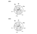
- FIG. 7A is a vertical cross-sectional view showing a state in which the electrode contact portion is formed so as to be bent with respect to the annular welded portion.
- FIG. 7B is a vertical cross-sectional view showing a state in which the electrode contact portion is elastically deformed. It is a figure which shows the manufacturing method of the annular plate in order.
- FIG. 8A is a plan view showing the structure of a flat plate used as a material for the annular plate.
- FIG. 8B is a plan view showing a flat plate in the process of processing.
- FIG. 8C is a plan view showing a flat plate after processing.
- Embodiment 1 The motor according to the first embodiment will be described with reference to FIGS. 1 to 5.
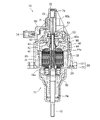
- FIG. 1 is a vertical sectional view showing a configuration of a motor according to the first embodiment.
- FIG. 2 is a plan view showing the configuration of the motor according to the first embodiment.
- FIG. 3 is a vertical cross-sectional view when joining the stator ASSY 11 and the case ASSY 12. Note that FIG. 3 illustrates a portion of the stator ASSY 11 corresponding to the upper / exterior member 21.
- the motor according to the first embodiment is, for example, a linear motor, and includes a stator ASSY 11, a case ASSY 12, and an output shaft 13.
- the stator ASSY 11 constitutes the lower part of the motor, and the case ASSY 12 constitutes the upper part of the motor. Although the details will be described later, the stator ASSY 11 and the case ASSY 12 are joined in the rotation axis direction of the motor by using a hot wire welding method. At this time, the stator ASSY 11 and the case ASSY 12 are joined with an annular plate 90 used for hot wire welding sandwiched between them.
- the output shaft 13 is arranged at a substantially central portion of the stator ASSY 11 and the case ASSY 12.
- the output shaft 13 directly moves with respect to the stator ASSY 11 and the case ASSY 12.
- the output shaft 13 is supported with respect to the stator ASSY 11 so as to be reciprocally movable in the axial direction of the output shaft 13.
- the lower end of the output shaft 13 is mechanically connected to, for example, a valve or the like. Therefore, the motor can open and close the valve by reciprocating the output shaft 13 in the axial direction thereof.
- the stator ASSY 11 has a first exterior member 20, a stator 30, a rotor 40, bearings 51 and 52, a brush 53, and a bush 54.
- the first exterior member 20 has a tapered cylindrical shape and forms the outer shell of the stator ASSY 11.
- the first exterior member 20 covers the stator 30 and the rotor 40 from the outside thereof.
- the stator 30 and the rotor 40 are arranged coaxially.
- the rotor 40 rotates with respect to the stator 30.
- the output shaft 13 penetrates each center of the stator 30 and the rotor 40.
- the first exterior member 20 is made of, for example, a resin material.
- the first exterior member 20 is composed of an upper exterior member 21 and a lower exterior member 22.
- the upper exterior member 21 has a cylindrical shape and constitutes the upper portion of the first exterior member 20.
- the lower exterior member 22 has a tapered cylindrical shape and constitutes the lower portion of the first exterior member 20.
- the upper exterior member 21 and the lower exterior member 22 are joined by using, for example, bolts 23 or the like. At this time, the lower end of the upper exterior member 21 is inserted into the upper end of the lower exterior member 22.
- the stator 30 has a cylindrical shape.
- the stator 30 is fixed to the upper / exterior member 21. Further, the stator 30 has a magnet 31 and a yoke 32.
- Both the magnet 31 and the yoke 32 have an arc shape.
- the yoke 32 is arranged radially outside the stator 30 with respect to the magnet 31.
- the magnet 31 is, for example, a ferrite magnet, a permanent magnet, or the like.
- the yoke 32 is made of, for example, iron.
- the rotor 40 has a cylindrical shape.
- the rotor 40 is arranged inside the stator 30 in the radial direction. Further, the rotor 40 is rotatably supported by the upper / exterior member 21.
- the rotor 40 has a plurality of rotor cores 41, a plurality of coils 42, a commutator 43, a rotor shaft 44, and a resin member 45.
- the plurality of rotor cores 41 are arranged at equal intervals in the circumferential direction of the rotor 40. These rotor cores 41 are arranged so as to face the magnet 31 and the yoke 32 in the radial direction of the rotor 40.
- the plurality of coils 42 are wound around each rotor core 41, respectively.
- the commutator 43 has a plurality of electrodes. These electrodes are arranged at equal intervals in the circumferential direction of the rotor 40. Each electrode corresponds to each coil 42, respectively. One end of each coil 42 is electrically connected to the corresponding electrode.
- the brush 53 is fixed to the upper / exterior member 21.
- the brush 53 is arranged on the outer side in the radial direction of the commutator 43, and is in contact with each electrode of the commutator 43.
- the rotor shaft 44 is formed in a cylindrical shape.
- the rotor shaft 44 is inserted into and fitted into a central hole formed by a plurality of rotor cores 41. Further, the rotor shaft 44 is rotatably supported by the upper / exterior member 21 via the bearings 51 and 52.
- the rotor shaft 44 has a female threaded portion 44a.
- the female threaded portion 44a is formed on the inner peripheral surface of the rotor shaft 44.
- the output shaft 13 is arranged inside the rotor shaft 44.
- the output shaft 13 has a male screw portion 13a.
- the male screw portion 13a is formed on the outer peripheral surface of the output shaft 13.
- the male threaded portion 13a and the female threaded portion 44a are in mesh with each other.
- the bush 54 is fixed to the lower end of the upper exterior member 21 and is arranged inside the lower exterior member 22.
- the bush 54 supports the output shaft 13 so as to be movable in the axial direction thereof. Further, the bush 54 regulates the rotation of the output shaft 13. Therefore, when the rotor shaft 44 rotates, the output shaft 13 reciprocates in the axial direction inside the rotor shaft 44 because the rotation of the output shaft 13 is restricted by the bush 54.
- the resin member 45 integrally fixes a plurality of rotor cores 41, a plurality of coils 42, a commutator 43, and a rotor shaft 44. Therefore, when the rotor shaft 44 rotates, the plurality of rotor cores 41, the plurality of coils 42, and the commutator 43 rotate together with the rotor shaft 44.
- the female threaded portion 44a of the rotor shaft 44 may be formed by a part of the resin member 45 wrapping around inside the rotor shaft 44.
- the case ASSY 12 has a second exterior member 60, a position sensor 71, a sensor magnet 72, a sensor shaft 73, a spring 74, and an external terminal 75.
- the second exterior member 60 has a substantially conical shape and forms the outer shell of the case ASSY 12.
- the second exterior member 60 covers the position sensor 71, the sensor magnet 72, the sensor shaft 73, the spring 74, and the external terminal 75 from the outside thereof.
- the second exterior member 60 is made of, for example, a resin material.
- the second exterior member 60 has a plurality of outer surface ribs 60b and a plurality of inner surface ribs 60c.
- the outer surface rib 60b and the inner surface rib 60c reinforce the second exterior member 60.
- the inner rib 60c constitutes a thick portion.
- the outer surface rib 60b is provided on the outer surface of the second exterior member 60. These outer surface ribs 60b extend in the radial direction of the second exterior member 60. Further, the top surface (upper surface) of the outer surface rib 60b faces upward. The top surface is gradually inclined downward from the radially inner side to the radial outer side of the second exterior member 60.
- the inner surface rib 60c is provided on the inner surface of the second exterior member 60 so as to face the radial outer end of the outer surface rib 60b. These inner surface ribs 60c extend in the radial direction of the second exterior member 60. Further, the top surface (lower surface) of the inner surface rib 60c faces downward. The top surface is gradually inclined downward from the radially inner side to the radial outer side of the second exterior member 60.
- the position sensor 71 measures the strength of the magnetic field of the sensor magnet 72, and detects the axial position of the output shaft 13 based on the measured strength of the magnetic field.
- the sensor magnet 72 is built in the upper end of the sensor shaft 73. The lower end of the sensor shaft 73 can come into contact with the upper end of the output shaft 13. Further, the spring 74 is sandwiched between the second exterior member 60 and the sensor magnet 72 in a compressed state.
- the spring 74 is in a state in which the sensor magnet 72 and the sensor shaft 73 are always urged downward. Therefore, the sensor shaft 73 is always pressed against the output shaft 13. As a result, when the output shaft 13 reciprocates in the axial direction, the sensor magnet 72 is always pressed against the output shaft 13, so that the sensor magnet 72 can be interlocked with the reciprocating movement of the output shaft 13.
- the position sensor 71 measures the strength of the magnetic field of the sensor magnet 72 linked to the reciprocating movement of the output shaft 13. Further, the position sensor 71 detects the axial position of the output shaft 13 based on the strength of the measured magnetic field.
- the external terminal 75 is a part where electric power is supplied from the outside of the motor.
- the output shaft 13 reciprocates in its axial direction.
- the valve opens or closes with the reciprocating movement of the output shaft 13.
- the motor can open and close the valve by converting the rotation of the rotor 40 accompanying the input of electric energy into the axial movement of the output shaft 13. Then, the motor detects the valve opening degree based on the axial position of the output shaft 13 detected by the position sensor 71.
- FIG. 4 is a plan view showing the configuration of the annular plate 90.
- FIG. 5 is an enlargement of a main part of the annular plate 90.
- the upper exterior member 21 of the first exterior member 20 has a first joint surface 21a.
- the first joint surface 21a has an annular shape and is formed along the circumferential direction of the upper / exterior member 21.
- the second exterior member 60 has a second joint surface 60a.
- the second joint surface 60a has an annular shape and is formed along the circumferential direction of the second exterior member 60.
- the first joint surface 21a and the second joint surface 60a are surfaces facing each other at the time of joining the upper exterior member 21 and the second exterior member 60.
- the annular plate 90 is interposed between the first joint surface 21a and the second joint surface 60a.
- the annular plate 90 is arranged so as to surround the inner circumference of the opening edge portion of the upper / exterior member 21 and the inner circumference of the opening edge portion of the second exterior member 60.
- a conductive annular plate 90 is sandwiched between the joining surfaces 21a and 60a of the exterior members 21 and 60 formed of resin materials, and the annular plate 90 is sandwiched between them.
- the joining method applied to the motor according to the first embodiment is a method of joining the exterior members 21 and 60 to each other by a hot wire welding method.
- the annular plate 90 has an annular welding portion 91, a plurality of small cross-sectional area portions 92, and a pair of electrode contact portions 93.
- the annular plate 90 is made of a conductive metal material, for example, a SUS material.
- the annular welded portion 91 has an annular shape and has substantially the same diameter as the diameter of the first joint surface 21a and the second joint surface 60a. When the upper exterior member 21 and the second exterior member 60 are joined, the annular welded portion 91 is sandwiched between the first joint surface 21a and the second joint surface 60a to weld them. be.
- the plurality of small cross-sectional area portions 92 are provided in the annular welding portion 91.
- the number of the small cross-sectional area portions 92 is the same as the number of the inner surface ribs 60c of the second exterior member 60.
- the small cross-sectional area 92 is a portion having the smallest cross-sectional area in the annular welded portion 91, and is provided at a position facing the inner surface rib 60c in the annular welded portion 91. That is, the small cross-sectional area portion 92 is arranged at the same position as the circumferential position of the inner surface rib 60c in the circumferential direction of the second exterior member 60.
- the small cross-sectional area portion 92 is arranged corresponding to the position where the wall thickness of the resin material becomes the hottest. Further, the small cross-sectional area portion 92 is formed so that the cross-sectional area becomes smaller as the wall thickness of the inner surface rib 60c becomes thicker.
- the pair of electrode contact portions 93 are provided in the annular welding portion 91. Electrodes (not shown) can be contacted with each of these electrode contact portions 93.
- the electrode contact portion 93 projects radially outward from the outer peripheral portion of the annular welded portion 91. Therefore, even if the annular welding portion 91 is sandwiched between the first joint surface 21a and the second joint surface 60a, the electrode contact portion 93 is not sandwiched between them, and the electrodes can be easily contacted. It has become.
- the cross-sectional area of the small cross-sectional area portion 92 is the smallest, so that the electric resistance of the small cross-sectional area portion 92 is the largest. That is, among the annular welded portions 91, the calorific value of the small cross-sectional area portion 92 is the largest. In this way, the annular plate 90 can melt more resin material in the portion where the wall thickness of the resin material becomes thicker by providing the annular welding portion 91 with the small cross-sectional area portion 92.
- the amount of heat required for melting the exterior members is designed to be uniform in the circumferential direction.
- the cross-sectional area of the conventional annular plate used in the hot wire welding method is also made uniform in the circumferential direction.
- a small cross-sectional area portion 92 is provided in the annular welding portion 91 corresponding to the inner surface rib 60c which is a thick portion. Since the inner rib 60c has a thick wall, the amount of heat for melting it increases accordingly. On the other hand, since the small cross-sectional area 92 has the smallest cross-sectional area among the annular welded portions 91, the small cross-sectional area portion 92 has the largest calorific value among the annular welded portions 91.
- the thick portion is the inner rib 60c of the second exterior member 60, but the thick portion is not limited thereto.
- the wall thickness portion is provided on at least one of the first exterior member 20 and the second exterior member 60, and may be any one as long as it thickens the wall thickness at the joint portion between them.
- the motor according to the first embodiment has a first exterior member 20 having a first welded surface 21a, a second exterior member 60 having a second welded surface 60a facing the first welded surface 21a, and a first welded joint.
- An annular plate 90 is provided between the surface 21a and the second joining surface 60a, surrounds the inner circumference of the first exterior member 20 and the inner circumference of the second exterior member 60, and has a conductive annular plate 90.
- a pair of electrode contact portions provided in the annular welded portion 91, which is sandwiched between the first joint surface 21a and the second joint surface 60a and joined by welding between them, and the annular welded portion 91, in which the electrodes are in contact with each other.
- the annular welding portion 91 is provided so that the thickness of the thick portion becomes thicker. It has a small cross-sectional area portion 92 formed so that the cross-sectional area becomes small. Therefore, even if the wall thickness between the exterior members 20 and 60 is not constant, the motor can appropriately join the exterior members 20 and 60 by using the hot wire welding method.
- the annular welding portion 91 is sandwiched between the first joint surface 21a and the second joint surface 60a, and the electrodes are brought into contact with the pair of electrode contact portions 93, respectively.
- the calorific value of the small cross-sectional area portion 92 is made larger than the calorific value of the annular welded portion 91 other than the small cross-sectional area portion 92. 1
- the exterior member 20 and the second exterior member 60 are joined by welding. Therefore, as a method for manufacturing a motor, even if the wall thickness between the exterior members 20 and 60 is not constant, the exterior members 20 and 60 can be appropriately joined by using a hot wire welding method.
- Embodiment 2 The motor according to the second embodiment will be described with reference to FIGS. 6 and 7.
- FIG. 6 is a plan view showing the configuration of the annular plate 90 applied to the motor according to the second embodiment.
- FIG. 7 is a cross-sectional view showing a state in which the annular plate 90 is sandwiched between the upper exterior member 21 of the first exterior member 20 and the second exterior member 60.
- the annular plate 90 according to the first embodiment includes an electrode contact portion 93, whereas the annular plate 90 according to the second embodiment has an electrode contact portion 94. I have.
- the electrode contact portion 94 is formed so as to be bent from the outer peripheral portion of the annular welded portion 91 toward the central axis of the annular welded portion 91 (see FIG. 7A). Therefore, the electrode contact portion 94 absorbs the impact load when the electrodes are contacted as compared with the electrode contact portion 93 protruding radially outward from the outer peripheral portion of the annular welded portion 91, and the annular welded portion 94. It is difficult to convey to 91 (see FIG. 7B). In this way, the annular plate 90 can reduce the impact load transmitted from the electrode contact portion 94 to the annular welded portion 91 and suppress the vibration of the annular welded portion 91. Therefore, in the motor, the upper exterior member 21 and the second exterior member 60 are joined with high accuracy.
- the electrode when the electrode is brought into contact with the electrode contact portion 94, the electrode may be operated by a spring type or cylinder type device. When such a device is used, the applied load of the electrode to the electrode contact portion 94 varies. On the other hand, since the electrode contact portion 94 is formed so as to be bent with respect to the annular welding portion 91, even if the applied load from the electrode varies, the applied load is absorbed and attenuated.
- the electrode contact portion 94 is formed so as to be bent from the annular welded portion 91 toward the central axis of the annular welded portion 91. Therefore, the motor can make it difficult to transmit the impact load generated when the electrode comes into contact with the electrode contact portion 94 to the annular welding portion 91. Therefore, the motor can suppress the vibration of the annular welded portion 91 and perform the joining between the upper / exterior member 21 and the second exterior member 60 with high accuracy.
- Embodiment 3 The method for manufacturing the motor according to the third embodiment will be described with reference to FIG.
- FIG. 8 is a diagram showing the manufacturing method of the annular plate 90 in order. Note that FIG. 8 shows an example of manufacturing an annular plate 90 having an electrode contact portion 93.
- the annular plate 90 can be manufactured from, for example, a flat plate 90A.
- the flat plate 90A is obtained by punching a conductive metal plate.
- the electrode contact portion 93 and the slit 95 are previously formed on the flat plate 90A after the punching process.
- the flat plate 90A is plastically deformed so as to widen the width of the slit 95. Further, as shown in FIG. 8C, the flat plate 90A is plastically deformed so as to widen the width of the slit 95 until the entire flat plate 90A becomes annular.
- the annular welded portion 91 is formed on the flat plate 90A.
- the small cross-sectional area portion 92 is machined with respect to the annular welded portion 91 of the flat plate 90A shown in FIG. 8C according to the circumferential position and the wall thickness of the inner surface rib 60c.
- the annular plate 90 as shown in FIG. 4 is manufactured.
- the method of manufacturing the annular plate 90 from the flat plate 90A can improve the yield of the material as compared with the manufacturing method of punching in the state of the finished product shown in FIG.
- the electrode contact portion 93 is subjected to the annular welding portion 91.
- the electrode contact portion 94 may be formed by bending in the direction of the central axis of the above.
- the annular plate 90 plastically deforms the conductive flat plate 90A so as to widen the width of the slit 95 formed in the flat plate 90A, and the flat plate 90A is plastically deformed.
- the method of manufacturing a motor can improve the yield of the motor.
- any combination of embodiments can be freely combined, any component of each embodiment can be modified, or any component can be omitted in each embodiment. ..
- the motor by providing a small cross-sectional area portion on a conductive annular plate, even if the wall thickness of the joint portion between the exterior members is not constant, the motor can be appropriately joined by using the hot wire welding method. It is suitable for use in motors and the like.
- stator ASSY 12 case ASSY, 13 output shaft, 13a male screw part
- 20 first exterior member, 21 upper exterior member, 21a first joint surface, 22 lower exterior member, 23 bolt, 30 stator, 31 magnet, 32 yoke , 40 rotor, 41 rotor core, 42 coil, 43 commutator, 44 rotor shaft, 44a female thread part, 45 resin member, 51, 52 bearing, 53 brush, 54 bush, 60 second exterior member, 60a second joint surface, 60b outer surface rib, 60c inner surface rib, 71 sensor, 72 sensor magnet, 73 sensor shaft, 74 spring, 75 external terminal, 90 annular plate, 90A flat plate, 91 annular welding part, 92 small cross-sectional area part, 93,94 electrode contact Part, 95 slits.
Landscapes
- Engineering & Computer Science (AREA)
- Power Engineering (AREA)
- Manufacturing & Machinery (AREA)
- Manufacture Of Motors, Generators (AREA)
- Motor Or Generator Frames (AREA)
Abstract
モータは、第1接合面(21a)を有する第1外装部材(20)と、第1接合面(21a)と対向する第2接合面(60a)を有する第2外装部材(60)と、第1接合面(21a)と第2接合面(60a)との間に設けられ、第1外装部材(20)の内周及び第2外装部材(60)の内周を取り囲み、導電性を有する環状プレート(90)とを備え、環状プレート(90)は、第1接合面(21a)と第2接合面(60a)との間に挟み込まれ、それらの間を溶着によって接合した環状溶着部(91)と、環状溶着部(91)に設けられ、電極が接触する一対の電極接触部(93)と、第2外装部材(60)の内面リブ(60c)に対応して環状溶着部(91)に設けられ、内面リブ(92)の肉厚が厚くなる程、断面積が小さくなるように形成される小断面積部(92)とを有する。
Description
本開示は、モータ及びモータの製造方法に関する。
モータは、例えば、有底筒状のハウジングと、ハウジングの開口部を塞ぐ蓋体と、ハウジング内に組み込まれたステータと、ステータ内に隙間をおいて回転自在に設けられたロータとを備えている。このようなモータは、例えば、特許文献1に開示されている。
特許文献1に開示されたモータにおいては、外装部材となるハウジング及び蓋体が、共に合成樹脂で形成されている。ハウジング及び蓋体は、レーザ溶着法を用いて互いに接合されている。この特許文献1に開示されたモータにおいては、ハウジングと蓋体との間の肉厚が、一定であることを前提としている。このため、特許文献1に開示されたモータにおいては、ハウジングと蓋体との間の肉厚が一定でない場合、それらが適切に接合されないおそれがある。
ところで、上述したような、互いに合成樹脂で形成される外装部材同士を接合する方法には、レーザ溶着法を用いたものの他に、例えば、ホットワイヤ溶着法を用いたものがある。このホットワイヤ溶着法を用いた接合方法においても、上記問題が発生するおそれがある。
本開示は、上記のような課題を解決するためになされたもので、外装部材間の肉厚が一定でない場合でも、当該外装部材同士を、ホットワイヤ溶着法を用いて適切に接合することができるモータを提供することを目的とする。
本開示に係るモータは、第1接合面を有する第1外装部材と、第1接合面と対向する第2接合面を有する第2外装部材と、第1接合面と第2接合面との間に設けられ、第1外装部材の内周及び第2外装部材の内周を取り囲み、導電性を有する環状プレートとを備え、環状プレートは、第1接合面と第2接合面との間に挟み込まれ、それらの間を溶着によって接合した環状溶着部と、環状溶着部に設けられ、電極が接触する一対の電極接触部と、第1外装部材及び第2外装部材のうち、少なくともいずれか一方に設けられる肉厚部に対応して、環状溶着部に設けられ、肉厚部の肉厚が厚くなる程、断面積が小さくなるように形成される小断面積部とを有するものである。
本開示によれば、外装部材間の肉厚が一定でない場合でも、当該外装部材同士を、ホットワイヤ溶着法を用いて適切に接合することができる。
以下、本開示をより詳細に説明するために、本開示を実施するための形態について、添付の図面に従って説明する。
実施の形態1.
実施の形態1に係るモータについて、図1から図5を用いて説明する。
実施の形態1に係るモータについて、図1から図5を用いて説明する。
先ず、実施の形態1に係るモータの構成について、図1から図3を用いて説明する。図1は、実施の形態1に係るモータの構成を示す縦断面図である。図2は、実施の形態1に係るモータの構成を示す平面図である。図3は、ステータASSY11とケースASSY12とを接合するときの縦断面図である。なお、図3は、ステータASSY11の中で、上外装部材21に対応した部分を図示している。
図1から図3に示すように、実施の形態1に係るモータは、例えば、直動式のモータであって、ステータASSY11、ケースASSY12、及び、出力シャフト13を備えている。
ステータASSY11は、モータの下部を構成し、ケースASSY12は、モータの上部を構成している。詳細については後述するが、ステータASSY11とケースASSY12とは、ホットワイヤ溶着法を用いて、モータの回転軸方向において接合されている。このとき、ステータASSY11とケースASSY12とは、それらの間に、ホットワイヤ溶着時に用いられる環状プレート90を挟み込んだ状態で、接合されている。
出力シャフト13は、ステータASSY11及びケースASSY12の略中心部に配置されている。この出力シャフト13は、モータが回転すると、ステータASSY11及びケースASSY12に対して、直動する。具体的には、出力シャフト13は、ステータASSY11に対して、当該出力シャフト13の軸方向において、往復移動可能に支持されている。出力シャフト13の下端は、例えば、バルブ等と機械的に接続されている。このため、モータは、出力シャフト13をその軸方向に往復移動させることにより、バルブを開閉可能となっている。
ステータASSY11は、第1外装部材20、固定子30、回転子40、軸受51,52、ブラシ53、及び、ブッシュ54を有している。
第1外装部材20は、先細りした円筒状をなしており、ステータASSY11の外郭を形成している。この第1外装部材20は、固定子30及び回転子40をそれらの外側から覆っている。固定子30と回転子40とは、同軸状に配置されている。回転子40は、固定子30に対して回転する。出力シャフト13は、固定子30及び回転子40の各中心部を貫通している。
第1外装部材20は、例えば、樹脂材料で形成されている。この第1外装部材20は、上外装部材21及び下外装部材22から構成されている。上外装部材21は、円筒状をなしており、第1外装部材20の上部を構成している。下外装部材22は、先細りした円筒状をなしており、第1外装部材20の下部を構成している。上外装部材21と下外装部材22とは、例えば、ボルト23等を用いて接合されている。このとき、上外装部材21の下端は、下外装部材22の上端内に挿入されている。
固定子30は、円筒状をなしている。この固定子30は、上外装部材21に固定されている。また、固定子30は、マグネット31及びヨーク32を有している。
マグネット31及びヨーク32は、共に円弧状をなしている。ヨーク32は、マグネット31よりも固定子30の径方向外側に配置されている。マグネット31は、例えば、フェライト磁石又は永久磁石等である。ヨーク32は、例えば、鉄で形成されている。
回転子40は、円筒状をなしている。この回転子40は、固定子30の径方向内側に配置されている。また、回転子40は、上外装部材21に回転可能に支持されている。
回転子40は、複数のロータコア41、複数のコイル42、整流子43、ロータシャフト44、及び、樹脂部材45を有している。
複数のロータコア41は、回転子40の周方向において、等間隔で配置されている。これらのロータコア41は、マグネット31及びヨーク32に対して、回転子40の径方向において対向するように配置されている。
複数のコイル42は、各ロータコア41にそれぞれ巻回されている。整流子43は、複数の電極を有している。これらの電極は、回転子40の周方向において、等間隔で配置されている。各電極は、各コイル42にそれぞれ対応している。各コイル42の一端は、対応する電極と電気的に接続されている。
これに対して、ブラシ53は、上外装部材21に固定されている。このブラシ53は、整流子43の径方向外側に配置されており、当該整流子43の各電極に接触可能となっている。
ロータシャフト44は、円筒状に形成されている。このロータシャフト44は、複数のロータコア41によって形成された中心孔に挿入されて、それらに嵌合している。また、ロータシャフト44は、上記軸受51,52を介して、上外装部材21に回転可能に支持されている。
ロータシャフト44は、雌ねじ部44aを有している。この雌ねじ部44aは、ロータシャフト44の内周面に形成されている。
これに対して、出力シャフト13は、ロータシャフト44の内部に配置されている。この出力シャフト13は、雄ねじ部13aを有している。雄ねじ部13aは、出力シャフト13の外周面に形成されている。雄ねじ部13aと雌ねじ部44aとは、噛み合っている。
また、ブッシュ54は、上外装部材21の下端に固定されており、下外装部材22の内部に配置されている。このブッシュ54は、出力シャフト13をその軸方向に移動可能に支持している。また、ブッシュ54は、出力シャフト13の回転を規制する。このため、ロータシャフト44が回転した場合、出力シャフト13は、ブッシュ54によって回転が規制されているため、ロータシャフト44の内部において軸方向に往復移動する。
樹脂部材45は、複数のロータコア41、複数のコイル42、整流子43、及び、ロータシャフト44を一体的に固定している。このため、ロータシャフト44が回転した場合、複数のロータコア41、複数のコイル42、及び、整流子43は、当該ロータシャフト44と共に回転する。なお、ロータシャフト44の雌ねじ部44aは、樹脂部材45の一部分が、ロータシャフト44の内部に回り込むことによって形成されても良い。
ケースASSY12は、第2外装部材60、位置センサ71、センサ用マグネット72、センサシャフト73、ばね74、及び、外部ターミナル75を有している。
第2外装部材60は、略円錐状をなしており、ケースASSY12の外郭を形成している。この第2外装部材60は、位置センサ71、センサ用マグネット72、センサシャフト73、ばね74、及び、外部ターミナル75をそれらの外側から覆っている。第2外装部材60は、例えば、樹脂材料で形成されている。
第2外装部材60は、複数の外面リブ60b及び複数の内面リブ60cを有している。外面リブ60b及び内面リブ60cは、第2外装部材60を補強するものである。なお、内面リブ60cは、肉厚部を構成するものである。
外面リブ60bは、第2外装部材60の外面に設けられている。これらの外面リブ60bは、第2外装部材60の径方向において延びている。また、外面リブ60bの頂面(上面)は、上方に向いている。この頂面は、第2外装部材60の径方向内側から径方向外側に向かうに従って、徐々に下方に向けて傾斜している。
内面リブ60cは、第2外装部材60の内面において、外面リブ60bの径方向外端と対向して設けられている。これらの内面リブ60cは、第2外装部材60の径方向において延びている。また、内面リブ60cの頂面(下面)は、下方に向いている。この頂面は、第2外装部材60の径方向内側から径方向外側に向かうに従って、徐々に下方に向けて傾斜している。
位置センサ71は、センサ用マグネット72の磁界の強さを計測し、この計測した磁界の強さに基づいて、出力シャフト13の軸方向位置を検出する。センサ用マグネット72は、センサシャフト73の上端に内蔵されている。このセンサシャフト73の下端は、出力シャフト13の上端に当接可能となっている。また、ばね74は、第2外装部材60とセンサ用マグネット72との間において、圧縮状態で挟み込まれている。
このため、ばね74は、センサ用マグネット72及びセンサシャフト73を、常に下方に向けて付勢した状態となっている。よって、センサシャフト73は、出力シャフト13に対して、常に押し付けられた状態となっている。この結果、センサ用マグネット72は、出力シャフト13が軸方向において往復移動すると、その出力シャフト13に常に押し付けられているため、当該出力シャフト13の往復移動に対して連動することができる。
これに対して、位置センサ71は、出力シャフト13の往復移動に連動するセンサ用マグネット72の磁界の強さを計測する。また、位置センサ71この計測した磁界の強さに基づいて、出力シャフト13の軸方向位置を検出する。
外部ターミナル75は、モータの外部から電力が供給される部位である。
従って、モータは、上記構成をなすことにより、当該モータの外部から供給された電力が、外部ターミナル75に入力されると、電流が、ブラシ53及び回転子40の整流子43を介して、各ロータコア41に巻回されるコイル42に流れる。このため、各ロータコア41は、N極とS極とに分極して磁化する。そして、回転子40の各ロータコア41は、固定子30のマグネット31の磁力に引き付けられる。このとき、固定子30においては、マグネット31とヨーク32とが磁気回路を構成する。この結果、回転子40は、固定子30対して回転する。
これに対応して、出力シャフト13は、その軸方向において往復移動する。このとき、バルブが出力シャフト13に接続される場合、当該バルブは、その出力シャフト13の往復移動に伴って、開動作又は閉動作する。このように、モータは、電気エネルギーの入力に伴う回転子40の回転を、出力シャフト13の軸方向への移動に変換することにより、バルブを開閉可能としている。そして、モータは、位置センサ71が検出した出力シャフト13の軸方向位置に基づいて、バルブ開度を検出する。
次に、実施の形態1に係るモータの接合構造の接合方法について、図3から図5を用いて説明する。図4は、環状プレート90の構成を示す平面図である。図5は、環状プレート90の要部拡大である。
第1外装部材20の上外装部材21は、第1接合面21aを有している。この第1接合面21aは、環状をなしており、上外装部材21の周方向に沿って形成されている。一方、第2外装部材60は、第2接合面60aを有している。この第2接合面60aは、環状をなしており、第2外装部材60の周方向に沿って形成されている。第1接合面21aと第2接合面60aとは、上外装部材21と第2外装部材60との接合時において、互いに対向し合う面である。
これに対して、環状プレート90は、第1接合面21aと第2接合面60aとの間に介在されている。この環状プレート90は、上外装部材21の開口縁部における内周、及び、第2外装部材60の開口縁部における内周を取り囲むように、配置されている。
実施の形態1に係るモータに適用される接合方法は、互いに樹脂材料で形成される外装部材21,60同士の接合面21a,60a間に、導電性を有する環状プレート90を挟み込み、その環状プレート90に通電させることにより、当該環状プレート90に当接する外装部材21,60の一部を融解させて、この融解させた外装部材21,60同士を凝固させることで、当該外装部材21,60同士を接合させる方法である。言い換えれば、実施の形態1に係るモータに適用される接合方法は、ホットワイヤ溶着法によって、外装部材21,60同士を接合させる方法である。
図4及び図5に示すように、環状プレート90は、環状溶着部91、複数の小断面積部92、及び、一対の電極接触部93を有している。この環状プレート90は、導電性を有する金属材料で形成されており、例えば、SUS材で形成されている。
環状溶着部91は、環状をなしており、第1接合面21a及び第2接合面60aの径寸法と略同じ径寸法を有している。この環状溶着部91は、上外装部材21と第2外装部材60とを接合する際に、第1接合面21aと第2接合面60aとの間に挟み込まれることで、それらを溶着させるものである。
複数の小断面積部92は、環状溶着部91に設けられている。この小断面積部92の数は、第2外装部材60の内面リブ60cの数と同じ数である。小断面積部92は、環状溶着部91の中で最も断面積が小さい部位であり、当該環状溶着部91において、内面リブ60cと対向する位置に設けられている。即ち、小断面積部92は、第2外装部材60の周方向において、内面リブ60cの周方向位置と同じ位置に配置されている。言い換えれば、小断面積部92は、樹脂材料の肉厚が最も熱くなる位置に対応して配置されている。また、小断面積部92は、内面リブ60cの肉厚が厚くなる程、断面積が小さくなるように形成されている。
一対の電極接触部93は、環状溶着部91に設けられている。これらの電極接触部93には、電極(図示省略)がそれぞれ接触可能となっている。電極接触部93は、環状溶着部91の外周部からその径方向外側に向けて突出している。このため、電極接触部93は、環状溶着部91が第1接合面21aと第2接合面60aとの間に挟み込まれても、それらの間に挟み込まれることはなく、電極の接触が容易となっている。
従って、2つの電極を一対の電極接触部93にそれぞれ接触させた状態で、当該2つの電極に電圧を印加すると、環状プレート90においては、電流が、一方の電極接触部93から、環状溶着部91を通って、他方の電極接触部93に流れることで、環状溶着部91が発熱する。
このとき、環状溶着部91の中でも、小断面積部92の断面積は、最も小さいため、当該小断面積部92の電気抵抗は、最も大きくなる。即ち、環状溶着部91の中でも、小断面積部92の発熱量は、最も大きくなる。このように、環状プレート90は、環状溶着部91に小断面積部92を設けることにより、樹脂材料の肉厚が厚くなる部分に対して、より多くの樹脂材料を溶かすことができる。
通常、共に樹脂材料で形成される外装部材間の肉厚が周方向において均一である場合、それらの外装部材の溶融に必要な熱量は、その周方向において均一になるように設計される。これに対応して、ホットワイヤ溶着法で用いられる従来の環状プレートの断面積も、その周方向において均一とされる。
しかしながら、外装部品に肉厚部が形成される場合、外装部材の溶融に必要な熱量は、その肉厚部の肉厚に応じて設定する必要がある。そこで、モータにおいては、肉厚部となる内面リブ60cに対応して、小断面積部92が環状溶着部91に設けられている。内面リブ60cは、肉厚となるため、その分、それを溶融するための熱量は、大きくなる。これに対して、小断面積部92は、その断面積が環状溶着部91の中で最も小さいため、当該環状溶着部91の中でも、最も大きな発熱量を有する。
なお、上述した実施の形態1に係るモータにおいては、肉厚部を、第2外装部材60の内面リブ60cとしているが、肉厚部は、それに限定されるものではない。肉厚部は、第1外装部材20及び第2外装部材60のうち、少なくともいずれか一方に設けられるものであり、それらの間の接合部における肉厚を厚くするものであれば良い。
以上、実施の形態1に係るモータは、第1接合面21aを有する第1外装部材20と、第1接合面21aと対向する第2接合面60aを有する第2外装部材60と、第1接合面21aと第2接合面60aとの間に設けられ、第1外装部材20の内周及び第2外装部材60の内周を取り囲み、導電性を有する環状プレート90とを備え、環状プレート90は、第1接合面21aと第2接合面60aとの間に挟み込まれ、それらの間を溶着によって接合した環状溶着部91と、環状溶着部91に設けられ、電極が接触する一対の電極接触部93と、第1外装部材20及び第2外装部材60のうち、少なくともいずれか一方に設けられる肉厚部に対応して、環状溶着部91に設けられ、肉厚部の肉厚が厚くなる程、断面積が小さくなるように形成される小断面積部92とを有する。このため、モータは、外装部材20,60間の肉厚が一定でない場合でも、当該外装部材20,60を、ホットワイヤ溶着法を用いて適切に接合することができる。
また、実施の形態1に係るモータの製造方法は、第1接合面21aと第2接合面60aとの間に、環状溶着部91を挟み込み、一対の電極接触部93に、電極をそれぞれ接触させ、電極に電圧を印加して、環状溶着部91に通電させることにより、小断面積部92の発熱量を、当該小断面積部92以外の環状溶着部91における発熱量よりも大きくし、第1外装部材20と第2外装部材60とを溶着によって接合する。このため、モータの製造方法は、外装部材20,60間の肉厚が一定でない場合でも、当該外装部材20,60を、ホットワイヤ溶着法を用いて適切に接合することができる。
実施の形態2.
実施の形態2に係るモータについて、図6及び図7を用いて説明する。
実施の形態2に係るモータについて、図6及び図7を用いて説明する。
図6は、実施の形態2に係るモータに適用される環状プレート90の構成を示す平面図である。図7は、第1外装部材20の上外装部材21と第2外装部材60との間に環状プレート90を挟み込んだ状態を示す断面図である。
図6及び図7に示すように、実施の形態1に係る環状プレート90は、電極接触部93を備えているのに対して、実施の形態2に係る環状プレート90は、電極接触部94を備えている。
電極接触部94は、環状溶着部91の外周部から当該環状溶着部91の中心軸方向に向けて折り曲げられるように形成されている(図7A参照)。このため、電極接触部94は、環状溶着部91の外周部からその径方向外側に向けて突出する電極接触部93と比べて、電極が接触されたときの衝撃荷重を吸収し、環状溶着部91に伝わり難くしている(図7B参照)。このように、環状プレート90は、電極接触部94から環状溶着部91に伝わる衝撃荷重を減少させて、当該環状溶着部91の振動を抑えることができる。このため、モータにおいては、上外装部材21と第2外装部材60とが高精度に接合される。
具体的には、電極接触部94に電極を接触させる場合、その電極は、ばね式又はシリンダ式の装置によって操作されることがある。このような装置を使用するときには、電極の電極接触部94に対する当て荷重に、ばらつきが生じる。これに対して、電極接触部94は、環状溶着部91に対して折り曲げられるように形成されているため、電極からの当て荷重にばらつきが生じても、その当て荷重を吸収して減衰させる。
以上、実施の形態2に係るモータにおいては、電極接触部94が、環状溶着部91から当該環状溶着部91の中心軸方向に向けて折り曲げられるように形成される。このため、モータは、電極が電極接触部94に接触したときに発生する衝撃荷重を、環状溶着部91に伝え難くすることができる。よって、モータは、環状溶着部91の振動を抑えて、上外装部材21と第2外装部材60との接合を高精度に行うことができる。
実施の形態3.
実施の形態3に係るモータの製造方法について、図8を用いて説明する。
実施の形態3に係るモータの製造方法について、図8を用いて説明する。
図8は、環状プレート90の製造方法を順に示す図である。なお、図8は、電極接触部93を有する環状プレート90を製造する例を示している。
先ず、図8Aに示すように、環状プレート90は、例えば、平板90Aから製造可能となっている。平板90Aは、導電性を有する金属板を打ち抜き加工することで得られるものである。打ち抜き加工後の平板90Aには、電極接触部93及びスリット95が予め形成されている。
次いで、図8Bに示すように、平板90Aは、スリット95の幅を広げるように塑性変形される。更に、図8Cに示すように、平板90Aは、全体が環状になるまで、スリット95の幅を広げるように塑性変形される。
そして、図8Cに示すように、平板90Aには、環状溶着部91が形成される。続いて、図8Cに示した平板90Aの環状溶着部91に対して、内面リブ60cの周方向位置及び肉厚に応じて、小断面積部92が加工される。この結果、図4に示すような、環状プレート90が製造される。
上述したように、平板90Aから環状プレート90を製造する方法は、図4に示した完成品の状態で打ち抜き加工する製造方法と比べて、材料の歩留まりを向上させることができる。
なお、電極接触部94を有する環状プレート90を製造する場合には、例えば、上述したように、電極接触部93を有する環状プレート90を製造した後、その電極接触部93を、環状溶着部91の中心軸方向に向けて折り曲げて、電極接触部94を形成させれば良い。
以上、実施の形態3に係るモータの製造方法においては、環状プレート90が、導電性を有する平板90Aを、当該平板90Aに形成されているスリット95の幅を広げるように塑性変形させ、その平板90Aを環状にすることによって製造される。このため、モータの製造方法は、モータの歩留まりを向上させることができる。
なお、本開示はその開示の範囲内において、各実施の形態の自由な組み合わせ、あるいは各実施の形態の任意の構成要素の変形、もしくは各実施の形態において任意の構成要素の省略が可能である。
本開示に係るモータは、導電性を有する環状プレートに小断面積部を設けることで、外装部材間における接合部の肉厚が一定でない場合でも、ホットワイヤ溶着法を用いて適切に接合することができ、モータ等に用いるのに適している。
11 ステータASSY、12 ケースASSY、13 出力シャフト、13a 雄ねじ部、20 第1外装部材、21 上外装部材、21a 第1接合面、22 下外装部材、23 ボルト、30 固定子、31 マグネット、32 ヨーク、40 回転子、41 ロータコア、42 コイル、43 整流子、44 ロータシャフト、44a 雌ねじ部、45 樹脂部材、51,52 軸受、53 ブラシ、54 ブッシュ、60 第2外装部材、60a 第2接合面、60b 外面リブ、60c 内面リブ、71 センサ、72 センサ用マグネット、73 センサシャフト、74 ばね、75 外部ターミナル、90 環状プレート、90A 平板、91 環状溶着部、92 小断面積部、93,94 電極接触部、95 スリット。
Claims (4)
- 第1接合面を有する第1外装部材と、
前記第1接合面と対向する第2接合面を有する第2外装部材と、
前記第1接合面と前記第2接合面との間に設けられ、前記第1外装部材の内周及び前記第2外装部材の内周を取り囲み、導電性を有する環状プレートとを備え、
前記環状プレートは、
前記第1接合面と前記第2接合面との間に挟み込まれ、それらの間を溶着によって接合した環状溶着部と、
前記環状溶着部に設けられ、電極が接触する一対の電極接触部と、
前記第1外装部材及び前記第2外装部材のうち、少なくともいずれか一方に設けられる肉厚部に対応して、前記環状溶着部に設けられ、前記肉厚部の肉厚が厚くなる程、断面積が小さくなるように形成される小断面積部とを有する
ことを特徴とするモータ。 - 前記電極接触部は、
前記環状溶着部から当該環状溶着部の中心軸方向に向けて折り曲げられるように形成される
ことを特徴とする請求項1記載のモータ。 - 請求項1又は請求項2記載のモータを製造する製造方法であって、
前記第1接合面と前記第2接合面との間に、前記環状溶着部を挟み込み、
前記一対の電極接触部に、電極をそれぞれ接触させ、
前記電極に電圧を印加して、前記環状溶着部に通電させることにより、前記小断面積部の発熱量を、当該小断面積部以外の前記環状溶着部における発熱量よりも大きくし、前記第1外装部材と前記第2外装部材とを溶着によって接合する
ことを特徴とするモータの製造方法。 - 前記環状プレートは、
導電性を有する平板を、当該平板に形成されているスリットの幅を広げるように塑性変形させ、前記平板を環状にすることによって製造される
ことを特徴とする請求項3記載のモータの製造方法。
Priority Applications (2)
| Application Number | Priority Date | Filing Date | Title |
|---|---|---|---|
| JP2022554176A JP7205008B2 (ja) | 2020-11-06 | 2020-11-06 | モータ及びモータの製造方法 |
| PCT/JP2020/041464 WO2022097253A1 (ja) | 2020-11-06 | 2020-11-06 | モータ及びモータの製造方法 |
Applications Claiming Priority (1)
| Application Number | Priority Date | Filing Date | Title |
|---|---|---|---|
| PCT/JP2020/041464 WO2022097253A1 (ja) | 2020-11-06 | 2020-11-06 | モータ及びモータの製造方法 |
Publications (1)
| Publication Number | Publication Date |
|---|---|
| WO2022097253A1 true WO2022097253A1 (ja) | 2022-05-12 |
Family
ID=81456994
Family Applications (1)
| Application Number | Title | Priority Date | Filing Date |
|---|---|---|---|
| PCT/JP2020/041464 Ceased WO2022097253A1 (ja) | 2020-11-06 | 2020-11-06 | モータ及びモータの製造方法 |
Country Status (2)
| Country | Link |
|---|---|
| JP (1) | JP7205008B2 (ja) |
| WO (1) | WO2022097253A1 (ja) |
Citations (3)
| Publication number | Priority date | Publication date | Assignee | Title |
|---|---|---|---|---|
| JP2011226610A (ja) * | 2010-04-22 | 2011-11-10 | Nippon Pillar Packing Co Ltd | 溶着継手及びその溶着方法 |
| JP2020036388A (ja) * | 2018-08-27 | 2020-03-05 | 三菱電機株式会社 | モータ及びモータ製造方法 |
| JP2020044844A (ja) * | 2019-12-03 | 2020-03-26 | 株式会社フジクラ | 接合構造体 |
Family Cites Families (1)
| Publication number | Priority date | Publication date | Assignee | Title |
|---|---|---|---|---|
| JPS6032264U (ja) * | 1983-08-08 | 1985-03-05 | 斉藤 恵三 | 注射剤用管びんのキヤツプ |
-
2020
- 2020-11-06 JP JP2022554176A patent/JP7205008B2/ja active Active
- 2020-11-06 WO PCT/JP2020/041464 patent/WO2022097253A1/ja not_active Ceased
Patent Citations (3)
| Publication number | Priority date | Publication date | Assignee | Title |
|---|---|---|---|---|
| JP2011226610A (ja) * | 2010-04-22 | 2011-11-10 | Nippon Pillar Packing Co Ltd | 溶着継手及びその溶着方法 |
| JP2020036388A (ja) * | 2018-08-27 | 2020-03-05 | 三菱電機株式会社 | モータ及びモータ製造方法 |
| JP2020044844A (ja) * | 2019-12-03 | 2020-03-26 | 株式会社フジクラ | 接合構造体 |
Also Published As
| Publication number | Publication date |
|---|---|
| JPWO2022097253A1 (ja) | 2022-05-12 |
| JP7205008B2 (ja) | 2023-01-16 |
Similar Documents
| Publication | Publication Date | Title |
|---|---|---|
| WO2019039518A1 (ja) | 分割コア連結体および電機子の製造方法 | |
| JPWO2020017133A1 (ja) | 分布巻ラジアルギャップ型回転電機及びその固定子 | |
| JP5920319B2 (ja) | ロータ固定構造および回転電機 | |
| WO2018110300A1 (ja) | 回転電機の固定子鉄心およびその製造方法 | |
| WO2020255435A1 (ja) | アキシャルギャップ型回転電機 | |
| US9425658B2 (en) | Rotor and rotating electric machine having the same | |
| US20230005687A1 (en) | Electromagnetic relay and method of manufacturing electromagnetic relay | |
| JP5960541B2 (ja) | 巻線の溶接構造、端子及びステータ | |
| JP5277743B2 (ja) | 回転電機 | |
| CN103378694B (zh) | 旋转电机 | |
| WO2022097253A1 (ja) | モータ及びモータの製造方法 | |
| JP5595135B2 (ja) | 2相ハイブリッド型回転電機 | |
| JP6246416B2 (ja) | 回転電機 | |
| JP6754961B2 (ja) | モータ | |
| JP5487020B2 (ja) | 回転電機 | |
| CN113945313A (zh) | 转矩检测传感器 | |
| JP4121083B2 (ja) | ブラシレスオルタネータ用界磁コイルのボビン装置 | |
| US7514837B2 (en) | Brushless alternator | |
| JP7063671B2 (ja) | 回転電機、及び回転電機の製造方法 | |
| US20080278024A1 (en) | Radial stepping motor | |
| JP2018050461A (ja) | モータおよびモータの製造方法 | |
| JP7413990B2 (ja) | 回転電機のロータ | |
| JP7515028B1 (ja) | コアレスモータ | |
| WO2020250600A1 (ja) | 整流子と巻線との接続構造及びそれを有するロータ、モータ、並びに整流子と巻線との接続方法 | |
| JP7386516B2 (ja) | コアレス回転電気機械およびこれに用いる円環コイル |
Legal Events
| Date | Code | Title | Description |
|---|---|---|---|
| 121 | Ep: the epo has been informed by wipo that ep was designated in this application |
Ref document number: 20960806 Country of ref document: EP Kind code of ref document: A1 |
|
| ENP | Entry into the national phase |
Ref document number: 2022554176 Country of ref document: JP Kind code of ref document: A |
|
| NENP | Non-entry into the national phase |
Ref country code: DE |
|
| 122 | Ep: pct application non-entry in european phase |
Ref document number: 20960806 Country of ref document: EP Kind code of ref document: A1 |