WO2022092213A1 - Méthode de fabrication d'un article de protection jetable - Google Patents
Méthode de fabrication d'un article de protection jetable Download PDFInfo
- Publication number
- WO2022092213A1 WO2022092213A1 PCT/JP2021/039847 JP2021039847W WO2022092213A1 WO 2022092213 A1 WO2022092213 A1 WO 2022092213A1 JP 2021039847 W JP2021039847 W JP 2021039847W WO 2022092213 A1 WO2022092213 A1 WO 2022092213A1
- Authority
- WO
- WIPO (PCT)
- Prior art keywords
- lotion
- hydrophilic
- top sheet
- sheet
- fluid nozzle
- Prior art date
Links
- 238000000034 method Methods 0.000 title claims abstract description 50
- 238000004519 manufacturing process Methods 0.000 title claims abstract description 41
- 239000006210 lotion Substances 0.000 claims abstract description 192
- 239000012530 fluid Substances 0.000 claims abstract description 59
- 238000005507 spraying Methods 0.000 claims abstract description 24
- 238000002156 mixing Methods 0.000 claims abstract description 9
- 239000004745 nonwoven fabric Substances 0.000 claims description 77
- PEDCQBHIVMGVHV-UHFFFAOYSA-N Glycerine Chemical compound OCC(O)CO PEDCQBHIVMGVHV-UHFFFAOYSA-N 0.000 claims description 64
- 239000000835 fiber Substances 0.000 claims description 50
- 239000007921 spray Substances 0.000 claims description 45
- XLYOFNOQVPJJNP-UHFFFAOYSA-N water Substances O XLYOFNOQVPJJNP-UHFFFAOYSA-N 0.000 claims description 39
- 235000011187 glycerol Nutrition 0.000 claims description 32
- 239000002250 absorbent Substances 0.000 claims description 22
- 239000007788 liquid Substances 0.000 claims description 22
- 239000002245 particle Substances 0.000 claims description 21
- 230000002745 absorbent Effects 0.000 claims description 18
- 239000003595 mist Substances 0.000 claims description 3
- 239000004831 Hot glue Substances 0.000 description 41
- 239000006096 absorbing agent Substances 0.000 description 36
- 239000000463 material Substances 0.000 description 29
- 238000012360 testing method Methods 0.000 description 26
- 239000007789 gas Substances 0.000 description 22
- 238000005259 measurement Methods 0.000 description 20
- 230000000630 rising effect Effects 0.000 description 19
- 229920000642 polymer Polymers 0.000 description 17
- 238000010521 absorption reaction Methods 0.000 description 16
- 230000000694 effects Effects 0.000 description 16
- 238000000576 coating method Methods 0.000 description 15
- 230000008602 contraction Effects 0.000 description 15
- 238000005520 cutting process Methods 0.000 description 15
- 239000000523 sample Substances 0.000 description 14
- 210000002414 leg Anatomy 0.000 description 13
- -1 polypropylene Polymers 0.000 description 13
- 239000000047 product Substances 0.000 description 13
- 238000003466 welding Methods 0.000 description 12
- 238000005304 joining Methods 0.000 description 11
- 230000014759 maintenance of location Effects 0.000 description 11
- 238000004806 packaging method and process Methods 0.000 description 11
- 239000000853 adhesive Substances 0.000 description 10
- 230000001070 adhesive effect Effects 0.000 description 10
- 239000011248 coating agent Substances 0.000 description 10
- 230000009471 action Effects 0.000 description 8
- 229920001971 elastomer Polymers 0.000 description 8
- 230000002093 peripheral effect Effects 0.000 description 8
- 229920005989 resin Polymers 0.000 description 8
- 239000011347 resin Substances 0.000 description 8
- 239000004743 Polypropylene Substances 0.000 description 7
- 239000003795 chemical substances by application Substances 0.000 description 7
- 229920001155 polypropylene Polymers 0.000 description 7
- 230000008569 process Effects 0.000 description 7
- 239000005060 rubber Substances 0.000 description 7
- 239000002985 plastic film Substances 0.000 description 6
- 229920006255 plastic film Polymers 0.000 description 6
- 239000005871 repellent Substances 0.000 description 6
- 230000002209 hydrophobic effect Effects 0.000 description 5
- 229920002994 synthetic fiber Polymers 0.000 description 5
- 239000012209 synthetic fiber Substances 0.000 description 5
- 239000004698 Polyethylene Substances 0.000 description 4
- 238000004040 coloring Methods 0.000 description 4
- 238000001035 drying Methods 0.000 description 4
- 239000007924 injection Substances 0.000 description 4
- 238000002347 injection Methods 0.000 description 4
- 229920000573 polyethylene Polymers 0.000 description 4
- 238000012546 transfer Methods 0.000 description 4
- 244000043261 Hevea brasiliensis Species 0.000 description 3
- DNIAPMSPPWPWGF-UHFFFAOYSA-N Propylene glycol Chemical compound CC(O)CO DNIAPMSPPWPWGF-UHFFFAOYSA-N 0.000 description 3
- 210000001217 buttock Anatomy 0.000 description 3
- 239000002131 composite material Substances 0.000 description 3
- 239000000470 constituent Substances 0.000 description 3
- 238000010586 diagram Methods 0.000 description 3
- 229920003052 natural elastomer Polymers 0.000 description 3
- 229920001194 natural rubber Polymers 0.000 description 3
- 239000000123 paper Substances 0.000 description 3
- 229920000728 polyester Polymers 0.000 description 3
- 239000003755 preservative agent Substances 0.000 description 3
- 230000002335 preservative effect Effects 0.000 description 3
- 230000000717 retained effect Effects 0.000 description 3
- 238000007789 sealing Methods 0.000 description 3
- 238000003756 stirring Methods 0.000 description 3
- 229920003051 synthetic elastomer Polymers 0.000 description 3
- 239000005061 synthetic rubber Substances 0.000 description 3
- 239000010913 used oil Substances 0.000 description 3
- PUPZLCDOIYMWBV-UHFFFAOYSA-N (+/-)-1,3-Butanediol Chemical compound CC(O)CCO PUPZLCDOIYMWBV-UHFFFAOYSA-N 0.000 description 2
- IJGRMHOSHXDMSA-UHFFFAOYSA-N Atomic nitrogen Chemical compound N#N IJGRMHOSHXDMSA-UHFFFAOYSA-N 0.000 description 2
- RTZKZFJDLAIYFH-UHFFFAOYSA-N Diethyl ether Chemical compound CCOCC RTZKZFJDLAIYFH-UHFFFAOYSA-N 0.000 description 2
- 240000007643 Phytolacca americana Species 0.000 description 2
- FAPWRFPIFSIZLT-UHFFFAOYSA-M Sodium chloride Chemical compound [Na+].[Cl-] FAPWRFPIFSIZLT-UHFFFAOYSA-M 0.000 description 2
- XSQUKJJJFZCRTK-UHFFFAOYSA-N Urea Chemical compound NC(N)=O XSQUKJJJFZCRTK-UHFFFAOYSA-N 0.000 description 2
- 239000012190 activator Substances 0.000 description 2
- 239000000654 additive Substances 0.000 description 2
- 150000001336 alkenes Chemical class 0.000 description 2
- 230000015572 biosynthetic process Effects 0.000 description 2
- 239000012496 blank sample Substances 0.000 description 2
- 239000004202 carbamide Substances 0.000 description 2
- 235000014113 dietary fatty acids Nutrition 0.000 description 2
- 239000000284 extract Substances 0.000 description 2
- 239000004744 fabric Substances 0.000 description 2
- 239000000194 fatty acid Substances 0.000 description 2
- 229930195729 fatty acid Natural products 0.000 description 2
- 150000004665 fatty acids Chemical class 0.000 description 2
- 239000011521 glass Substances 0.000 description 2
- 238000010438 heat treatment Methods 0.000 description 2
- 239000012510 hollow fiber Substances 0.000 description 2
- 230000001771 impaired effect Effects 0.000 description 2
- 230000007794 irritation Effects 0.000 description 2
- JVTAAEKCZFNVCJ-UHFFFAOYSA-N lactic acid Chemical compound CC(O)C(O)=O JVTAAEKCZFNVCJ-UHFFFAOYSA-N 0.000 description 2
- 239000004750 melt-blown nonwoven Substances 0.000 description 2
- 230000002175 menstrual effect Effects 0.000 description 2
- 239000000203 mixture Substances 0.000 description 2
- 239000002736 nonionic surfactant Substances 0.000 description 2
- JRZJOMJEPLMPRA-UHFFFAOYSA-N olefin Natural products CCCCCCCC=C JRZJOMJEPLMPRA-UHFFFAOYSA-N 0.000 description 2
- 230000035699 permeability Effects 0.000 description 2
- 229920002647 polyamide Polymers 0.000 description 2
- 229920005672 polyolefin resin Polymers 0.000 description 2
- 229920001296 polysiloxane Polymers 0.000 description 2
- 239000000843 powder Substances 0.000 description 2
- 239000002994 raw material Substances 0.000 description 2
- 230000001603 reducing effect Effects 0.000 description 2
- 150000003839 salts Chemical class 0.000 description 2
- 238000007873 sieving Methods 0.000 description 2
- 239000000126 substance Substances 0.000 description 2
- 239000004094 surface-active agent Substances 0.000 description 2
- 238000010998 test method Methods 0.000 description 2
- 239000002562 thickening agent Substances 0.000 description 2
- 210000002700 urine Anatomy 0.000 description 2
- HDTRYLNUVZCQOY-UHFFFAOYSA-N α-D-glucopyranosyl-α-D-glucopyranoside Natural products OC1C(O)C(O)C(CO)OC1OC1C(O)C(O)C(O)C(CO)O1 HDTRYLNUVZCQOY-UHFFFAOYSA-N 0.000 description 1
- KIUKXJAPPMFGSW-DNGZLQJQSA-N (2S,3S,4S,5R,6R)-6-[(2S,3R,4R,5S,6R)-3-Acetamido-2-[(2S,3S,4R,5R,6R)-6-[(2R,3R,4R,5S,6R)-3-acetamido-2,5-dihydroxy-6-(hydroxymethyl)oxan-4-yl]oxy-2-carboxy-4,5-dihydroxyoxan-3-yl]oxy-5-hydroxy-6-(hydroxymethyl)oxan-4-yl]oxy-3,4,5-trihydroxyoxane-2-carboxylic acid Chemical compound CC(=O)N[C@H]1[C@H](O)O[C@H](CO)[C@@H](O)[C@@H]1O[C@H]1[C@H](O)[C@@H](O)[C@H](O[C@H]2[C@@H]([C@@H](O[C@H]3[C@@H]([C@@H](O)[C@H](O)[C@H](O3)C(O)=O)O)[C@H](O)[C@@H](CO)O2)NC(C)=O)[C@@H](C(O)=O)O1 KIUKXJAPPMFGSW-DNGZLQJQSA-N 0.000 description 1
- 229940058015 1,3-butylene glycol Drugs 0.000 description 1
- SMZOUWXMTYCWNB-UHFFFAOYSA-N 2-(2-methoxy-5-methylphenyl)ethanamine Chemical compound COC1=CC=C(C)C=C1CCN SMZOUWXMTYCWNB-UHFFFAOYSA-N 0.000 description 1
- NIXOWILDQLNWCW-UHFFFAOYSA-N 2-Propenoic acid Natural products OC(=O)C=C NIXOWILDQLNWCW-UHFFFAOYSA-N 0.000 description 1
- 241001474374 Blennius Species 0.000 description 1
- 229920002567 Chondroitin Polymers 0.000 description 1
- 102000008186 Collagen Human genes 0.000 description 1
- 108010035532 Collagen Proteins 0.000 description 1
- 229920000742 Cotton Polymers 0.000 description 1
- FBPFZTCFMRRESA-FSIIMWSLSA-N D-Glucitol Natural products OC[C@H](O)[C@H](O)[C@@H](O)[C@H](O)CO FBPFZTCFMRRESA-FSIIMWSLSA-N 0.000 description 1
- FBPFZTCFMRRESA-JGWLITMVSA-N D-glucitol Chemical compound OC[C@H](O)[C@@H](O)[C@H](O)[C@H](O)CO FBPFZTCFMRRESA-JGWLITMVSA-N 0.000 description 1
- 206010012735 Diarrhoea Diseases 0.000 description 1
- SNRUBQQJIBEYMU-UHFFFAOYSA-N Dodecane Natural products CCCCCCCCCCCC SNRUBQQJIBEYMU-UHFFFAOYSA-N 0.000 description 1
- 206010013786 Dry skin Diseases 0.000 description 1
- 102000016942 Elastin Human genes 0.000 description 1
- 108010014258 Elastin Proteins 0.000 description 1
- LFQSCWFLJHTTHZ-UHFFFAOYSA-N Ethanol Chemical compound CCO LFQSCWFLJHTTHZ-UHFFFAOYSA-N 0.000 description 1
- IAYPIBMASNFSPL-UHFFFAOYSA-N Ethylene oxide Chemical compound C1CO1 IAYPIBMASNFSPL-UHFFFAOYSA-N 0.000 description 1
- 208000010201 Exanthema Diseases 0.000 description 1
- 229920002683 Glycosaminoglycan Polymers 0.000 description 1
- HTTJABKRGRZYRN-UHFFFAOYSA-N Heparin Chemical compound OC1C(NC(=O)C)C(O)OC(COS(O)(=O)=O)C1OC1C(OS(O)(=O)=O)C(O)C(OC2C(C(OS(O)(=O)=O)C(OC3C(C(O)C(O)C(O3)C(O)=O)OS(O)(=O)=O)C(CO)O2)NS(O)(=O)=O)C(C(O)=O)O1 HTTJABKRGRZYRN-UHFFFAOYSA-N 0.000 description 1
- 239000004909 Moisturizer Substances 0.000 description 1
- 229910019142 PO4 Inorganic materials 0.000 description 1
- 239000004952 Polyamide Substances 0.000 description 1
- 239000002202 Polyethylene glycol Substances 0.000 description 1
- 229920000297 Rayon Polymers 0.000 description 1
- BLRPTPMANUNPDV-UHFFFAOYSA-N Silane Chemical compound [SiH4] BLRPTPMANUNPDV-UHFFFAOYSA-N 0.000 description 1
- 229920002334 Spandex Polymers 0.000 description 1
- 229920002472 Starch Polymers 0.000 description 1
- HDTRYLNUVZCQOY-WSWWMNSNSA-N Trehalose Natural products O[C@@H]1[C@@H](O)[C@@H](O)[C@@H](CO)O[C@@H]1O[C@@H]1[C@H](O)[C@@H](O)[C@@H](O)[C@@H](CO)O1 HDTRYLNUVZCQOY-WSWWMNSNSA-N 0.000 description 1
- TVXBFESIOXBWNM-UHFFFAOYSA-N Xylitol Natural products OCCC(O)C(O)C(O)CCO TVXBFESIOXBWNM-UHFFFAOYSA-N 0.000 description 1
- DPXJVFZANSGRMM-UHFFFAOYSA-N acetic acid;2,3,4,5,6-pentahydroxyhexanal;sodium Chemical compound [Na].CC(O)=O.OCC(O)C(O)C(O)C(O)C=O DPXJVFZANSGRMM-UHFFFAOYSA-N 0.000 description 1
- 230000000996 additive effect Effects 0.000 description 1
- 150000008051 alkyl sulfates Chemical class 0.000 description 1
- HDTRYLNUVZCQOY-LIZSDCNHSA-N alpha,alpha-trehalose Chemical compound O[C@@H]1[C@@H](O)[C@H](O)[C@@H](CO)O[C@@H]1O[C@@H]1[C@H](O)[C@@H](O)[C@H](O)[C@@H](CO)O1 HDTRYLNUVZCQOY-LIZSDCNHSA-N 0.000 description 1
- XAGFODPZIPBFFR-UHFFFAOYSA-N aluminium Chemical compound [Al] XAGFODPZIPBFFR-UHFFFAOYSA-N 0.000 description 1
- 229910052782 aluminium Inorganic materials 0.000 description 1
- 150000001413 amino acids Chemical class 0.000 description 1
- 125000000129 anionic group Chemical group 0.000 description 1
- 239000011324 bead Substances 0.000 description 1
- 235000019437 butane-1,3-diol Nutrition 0.000 description 1
- LLSDKQJKOVVTOJ-UHFFFAOYSA-L calcium chloride dihydrate Chemical compound O.O.[Cl-].[Cl-].[Ca+2] LLSDKQJKOVVTOJ-UHFFFAOYSA-L 0.000 description 1
- 229940052299 calcium chloride dihydrate Drugs 0.000 description 1
- 150000001720 carbohydrates Chemical class 0.000 description 1
- 239000001768 carboxy methyl cellulose Substances 0.000 description 1
- 229920002301 cellulose acetate Polymers 0.000 description 1
- 230000008859 change Effects 0.000 description 1
- DLGJWSVWTWEWBJ-HGGSSLSASA-N chondroitin Chemical compound CC(O)=N[C@@H]1[C@H](O)O[C@H](CO)[C@H](O)[C@@H]1OC1[C@H](O)[C@H](O)C=C(C(O)=O)O1 DLGJWSVWTWEWBJ-HGGSSLSASA-N 0.000 description 1
- 229920001436 collagen Polymers 0.000 description 1
- 239000003086 colorant Substances 0.000 description 1
- 230000006835 compression Effects 0.000 description 1
- 238000007906 compression Methods 0.000 description 1
- 238000012790 confirmation Methods 0.000 description 1
- 238000010924 continuous production Methods 0.000 description 1
- 229920001577 copolymer Polymers 0.000 description 1
- 238000002788 crimping Methods 0.000 description 1
- 238000004132 cross linking Methods 0.000 description 1
- 230000006866 deterioration Effects 0.000 description 1
- SZXQTJUDPRGNJN-UHFFFAOYSA-N dipropylene glycol Chemical compound OCCCOCCCO SZXQTJUDPRGNJN-UHFFFAOYSA-N 0.000 description 1
- 125000003438 dodecyl group Chemical group [H]C([H])([H])C([H])([H])C([H])([H])C([H])([H])C([H])([H])C([H])([H])C([H])([H])C([H])([H])C([H])([H])C([H])([H])C([H])([H])C([H])([H])* 0.000 description 1
- 230000037336 dry skin Effects 0.000 description 1
- 229920002549 elastin Polymers 0.000 description 1
- 239000000806 elastomer Substances 0.000 description 1
- 239000003995 emulsifying agent Substances 0.000 description 1
- 230000002708 enhancing effect Effects 0.000 description 1
- 230000007613 environmental effect Effects 0.000 description 1
- 238000011156 evaluation Methods 0.000 description 1
- 201000005884 exanthem Diseases 0.000 description 1
- 238000000605 extraction Methods 0.000 description 1
- 210000003608 fece Anatomy 0.000 description 1
- 239000010419 fine particle Substances 0.000 description 1
- 239000011888 foil Substances 0.000 description 1
- 235000013305 food Nutrition 0.000 description 1
- 229920000578 graft copolymer Polymers 0.000 description 1
- 239000008187 granular material Substances 0.000 description 1
- 238000007756 gravure coating Methods 0.000 description 1
- 229920000669 heparin Polymers 0.000 description 1
- 229960002897 heparin Drugs 0.000 description 1
- 229920002674 hyaluronan Polymers 0.000 description 1
- 229960003160 hyaluronic acid Drugs 0.000 description 1
- 239000011256 inorganic filler Substances 0.000 description 1
- 229910003475 inorganic filler Inorganic materials 0.000 description 1
- 238000007689 inspection Methods 0.000 description 1
- 238000004898 kneading Methods 0.000 description 1
- 239000004310 lactic acid Substances 0.000 description 1
- 235000014655 lactic acid Nutrition 0.000 description 1
- WRUGWIBCXHJTDG-UHFFFAOYSA-L magnesium sulfate heptahydrate Chemical compound O.O.O.O.O.O.O.[Mg+2].[O-]S([O-])(=O)=O WRUGWIBCXHJTDG-UHFFFAOYSA-L 0.000 description 1
- 229940061634 magnesium sulfate heptahydrate Drugs 0.000 description 1
- 238000000691 measurement method Methods 0.000 description 1
- 239000000155 melt Substances 0.000 description 1
- HEBKCHPVOIAQTA-UHFFFAOYSA-N meso ribitol Natural products OCC(O)C(O)C(O)CO HEBKCHPVOIAQTA-UHFFFAOYSA-N 0.000 description 1
- 244000005700 microbiome Species 0.000 description 1
- 230000027939 micturition Effects 0.000 description 1
- 230000001333 moisturizer Effects 0.000 description 1
- 230000003020 moisturizing effect Effects 0.000 description 1
- 229910052757 nitrogen Inorganic materials 0.000 description 1
- 125000002347 octyl group Chemical group [H]C([*])([H])C([H])([H])C([H])([H])C([H])([H])C([H])([H])C([H])([H])C([H])([H])C([H])([H])[H] 0.000 description 1
- 230000000149 penetrating effect Effects 0.000 description 1
- 239000010452 phosphate Substances 0.000 description 1
- 150000003014 phosphoric acid esters Chemical class 0.000 description 1
- 239000002504 physiological saline solution Substances 0.000 description 1
- 229920006149 polyester-amide block copolymer Polymers 0.000 description 1
- 229920001223 polyethylene glycol Polymers 0.000 description 1
- 229920000098 polyolefin Polymers 0.000 description 1
- 239000011148 porous material Substances 0.000 description 1
- 230000002265 prevention Effects 0.000 description 1
- 238000012545 processing Methods 0.000 description 1
- 206010037844 rash Diseases 0.000 description 1
- 239000002964 rayon Substances 0.000 description 1
- 238000005070 sampling Methods 0.000 description 1
- 239000012047 saturated solution Substances 0.000 description 1
- 210000002374 sebum Anatomy 0.000 description 1
- 239000011265 semifinished product Substances 0.000 description 1
- 230000001953 sensory effect Effects 0.000 description 1
- 238000000926 separation method Methods 0.000 description 1
- 238000009958 sewing Methods 0.000 description 1
- 229910000077 silane Inorganic materials 0.000 description 1
- 230000008591 skin barrier function Effects 0.000 description 1
- 235000019812 sodium carboxymethyl cellulose Nutrition 0.000 description 1
- 229920001027 sodium carboxymethylcellulose Polymers 0.000 description 1
- 239000011780 sodium chloride Substances 0.000 description 1
- 229940045920 sodium pyrrolidone carboxylate Drugs 0.000 description 1
- HYRLWUFWDYFEES-UHFFFAOYSA-M sodium;2-oxopyrrolidine-1-carboxylate Chemical compound [Na+].[O-]C(=O)N1CCCC1=O HYRLWUFWDYFEES-UHFFFAOYSA-M 0.000 description 1
- 239000007787 solid Substances 0.000 description 1
- 239000000243 solution Substances 0.000 description 1
- 239000000600 sorbitol Substances 0.000 description 1
- 229960002920 sorbitol Drugs 0.000 description 1
- 239000004759 spandex Substances 0.000 description 1
- 238000003892 spreading Methods 0.000 description 1
- 230000007480 spreading Effects 0.000 description 1
- 239000008107 starch Substances 0.000 description 1
- 235000019698 starch Nutrition 0.000 description 1
- 238000003860 storage Methods 0.000 description 1
- 239000002352 surface water Substances 0.000 description 1
- 229920001059 synthetic polymer Polymers 0.000 description 1
- 238000010792 warming Methods 0.000 description 1
- 230000037303 wrinkles Effects 0.000 description 1
- 239000000811 xylitol Substances 0.000 description 1
- 235000010447 xylitol Nutrition 0.000 description 1
- HEBKCHPVOIAQTA-SCDXWVJYSA-N xylitol Chemical compound OC[C@H](O)[C@@H](O)[C@H](O)CO HEBKCHPVOIAQTA-SCDXWVJYSA-N 0.000 description 1
- 229960002675 xylitol Drugs 0.000 description 1
Images


Classifications
-
- A—HUMAN NECESSITIES
- A61—MEDICAL OR VETERINARY SCIENCE; HYGIENE
- A61F—FILTERS IMPLANTABLE INTO BLOOD VESSELS; PROSTHESES; DEVICES PROVIDING PATENCY TO, OR PREVENTING COLLAPSING OF, TUBULAR STRUCTURES OF THE BODY, e.g. STENTS; ORTHOPAEDIC, NURSING OR CONTRACEPTIVE DEVICES; FOMENTATION; TREATMENT OR PROTECTION OF EYES OR EARS; BANDAGES, DRESSINGS OR ABSORBENT PADS; FIRST-AID KITS
- A61F13/00—Bandages or dressings; Absorbent pads
- A61F13/15—Absorbent pads, e.g. sanitary towels, swabs or tampons for external or internal application to the body; Supporting or fastening means therefor; Tampon applicators
- A61F13/51—Absorbent pads, e.g. sanitary towels, swabs or tampons for external or internal application to the body; Supporting or fastening means therefor; Tampon applicators characterised by the outer layers
- A61F13/511—Topsheet, i.e. the permeable cover or layer facing the skin
Definitions
- the present invention relates to a method for manufacturing disposable wear items such as disposable diapers and menstrual napkins.
- the wearer's skin becomes rough, especially rashes are often a problem.
- Reasons for this include physical irritation to the wearer's skin (friction and hardness) and deterioration of the skin barrier function due to dry skin.
- a top sheet made of a non-woven fabric contains a hydrophilic lotion (see Patent Document 1). Further, as a method of applying the hydrophilic lotion to the top sheet, it is also known to use spray coating (see Patent Documents 2 and 3) in addition to roll coating such as slot coating and gravure coating.
- the hydrophilic lotion in order for the hydrophilic lotion to function effectively, it is necessary that the hydrophilic lotion is sufficiently held in the top sheet, but the hydrophilic lotion is applied to the top sheet made of a non-woven fabric. In this case, the hydrophilic lotion is likely to be transferred to the member on the back side over time after production, and the hydrophilic lotion is less likely to be retained on the top sheet than expected.
- the main problem of the present invention is to improve the retention of the hydrophilic lotion on the top sheet and to suppress the sticky feeling caused by the hydrophilic lotion.
- the manufacturing method of disposable wearable goods that solved the above problems is as follows.
- ⁇ First aspect> It is made of a hydrophilic non-woven fabric and has a top sheet having a skin contact area in contact with the wearer's skin and a hydrophilic back side member in contact with the back side thereof.
- the skin contact area has a lotion-containing area containing a hydrophilic lotion containing water.
- a method of manufacturing disposable wear items As the hydrophilic lotion, a lotion having a viscosity of 50 to 500 mPa ⁇ s at a temperature of 20 ° C. is used. In forming the lotion-containing region, the hydrophilic lotion is atomized by mixing with a gas using a two-fluid nozzle and sprayed together with the gas toward the surface of the top sheet. The spraying amount of the hydrophilic lotion per unit spraying area is 0.1 to 5.0 ml / m 2 .
- a method of manufacturing a disposable wear article A method of manufacturing a disposable wear article.
- a hydrophilic lotion having a viscosity considering the retention in the top sheet is atomized by a two-fluid nozzle and sprayed onto the surface of the top sheet, so that even a viscous hydrophilic lotion is thinned on the top sheet. Moreover, it can be adhered evenly. Therefore, it is possible to suppress the sticky feeling caused by the hydrophilic lotion while improving the retention of the hydrophilic lotion on the top sheet.
- the top sheet is a non-woven fabric having a basis weight of 10 to 30 g / m 2 and a thickness of 0.4 to 1.4 mm, which is made of fibers having a fineness of 1 to 3 dtex.
- the droplets of the hydrophilic lotion immediately after being ejected from the two-fluid nozzle have a Sauter average particle diameter of 200 ⁇ m or less by the phase Doppler method.
- the short fiber non-woven fabric of this embodiment As the top sheet because a soft touch can be obtained. Then, when the hydrophilic lotion finely divided to the range of this embodiment is sprayed onto the surface of such a top sheet, the hydrophilic lotion easily penetrates into the inside of the top sheet, and as a result, the hydrophilic lotion on the surface of the top sheet. Content can be reduced. Therefore, when the amount of the hydrophilic lotion applied is the same, the sticky feeling on the surface of the top sheet can be further suppressed.
- the two-fluid nozzle is an external mixing type or an internal mixing type.
- the pressure of the gas in the two-fluid nozzle is 0.03 to 0.20 MPa, and the pressure is 0.03 to 0.20 MPa.
- the hydraulic pressure of the hydrophilic lotion in the two-fluid nozzle is 0.01 to 0.10 MPa.
- the two-fluid nozzle has a spray angle of 50 to 90 degrees.
- the angle between the spray axis of the two-fluid nozzle and the surface of the top sheet is a right angle, and the distance between the tip of the two-fluid nozzle and the surface of the top sheet is 35 to 60 mm.
- the hydrophilic lotion and the gas are vigorously sprayed from near the surface of the top sheet as in this embodiment, not only the hydrophilic lotion easily penetrates into the inside of the top sheet, but also the gas attached to the top sheet adheres to the top sheet. Excess hydrophilic lotion can be pushed deeply. Therefore, when the amount of the hydrophilic lotion applied is the same, the sticky feeling on the surface of the top sheet can be further suppressed.
- the gas pressure and the hydraulic pressure in the two-fluid nozzle mean the pressure immediately before the nozzle.
- the spray angle spray angle means the spread angle of the fog in the vicinity of the nozzle injection port (the maximum angle if it differs depending on the direction orthogonal to the spray axis).
- ⁇ Fourth aspect> While moving the surface of the top sheet so as to pass through the spray position of the two-fluid nozzle at a speed of 100 to 260 m / min, the flow rate of the gas in the two-fluid nozzle is 15.0 to 25.0 liters. / Minute, the flow rate of the hydrophilic lotion in the two-fluid nozzle is 0.5 to 2.5 liters / hour, gas flow rate: liquid flow rate is 600: 1 to 1200: 1, and the top from the two-fluid nozzle. Spraying the surface of the sheet with the hydrophilic lotion in the form of a mist, A method for manufacturing a disposable wear article according to a third aspect.
- the disposable wear articles of the first aspect can be produced by spraying the hydrophilic lotion under the conditions of this embodiment.
- the lotion-containing region has a dimension of 30 mm or more in the MD direction and a dimension of 5 mm or more in the CD direction.
- ⁇ Sixth aspect> The average coefficient of friction MIU on the surface of the lotion-containing region is 0.2 to 0.4.
- the average friction coefficient MIU of the lotion-containing region is within the above range because the physical irritation to the wearer's skin is reduced.
- the hydrophilic lotion contains 70 to 90% by weight of glycerin and 10 to 30% by weight of water.
- the hydrophilic lotion is not particularly limited, but the hydrophilic lotion of this embodiment is preferable because it is low in cost and has the above-mentioned viscosity even without a thickener or the like.
- the hydrophilic non-woven fabric and the absorbent element that absorbs and retains the liquid content of excrement are used as the back side member, and the top sheet is laminated on the hydrophilic non-woven fabric, and the surface of the top sheet is atomized with the hydrophilic.
- the back side member retains the hydrophilic lotion and surrounds it. It is preferable because it is difficult to scatter.
- the present invention it is possible to suppress the sticky feeling caused by the hydrophilic lotion while improving the retention of the hydrophilic lotion on the top sheet.
- FIG. 3 is a sectional view taken along the line 3-3 of FIG. (A) is a 4-4 cross-sectional view of FIG. 1, and (b) is a 5-5 cross-sectional view of FIG.
- A) is a 4-4 cross-sectional view of FIG. 1
- (b) is a 5-5 cross-sectional view of FIG.
- It is a perspective view of a pants type disposable diaper. It is a top view which shows the outer surface of the interior body in the unfolded state together with the outline of the exterior body. It is a top view which shows the outer surface of the interior body in the unfolded state together with the outline of the exterior body.
- the dotted pattern portion in the cross-sectional view shows an adhesive as a joining means for joining each component located on the front side and the back side thereof, and is a solid, bead, curtain, summit or spiral coating of hot melt adhesive, or a pattern coat.
- the fixed part of the elastic member is formed by (transfer of hot melt adhesive by the letterpress method), etc., or by coating the elastic member on the outer peripheral surface of the elastic member such as comb gun or sure wrap coating instead of or together with this. be.
- hot melt adhesive examples include EVA type, adhesive rubber type (elastomer type), olefin type, polyester / polyamide type and the like, but they can be used without particular limitation.
- a joining means for joining each component a means by welding a material such as a heat seal or an ultrasonic seal can also be used.
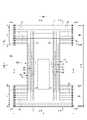
- the pants-type disposable diapers shown in FIGS. 1 to 6 include a rectangular front exterior body 12F constituting at least the waist circumference of the front body F and a rectangular rear exterior body 12B constituting at least the waist circumference of the back body B.
- the interior body 200 is provided inside the exterior bodies 12F and 12B so as to extend from the front exterior body 12F through the crotch portion to the rear exterior body 12B.
- Both sides of the front exterior body 12F and both sides of the rear exterior body 12B are joined to form a side seal 12A, whereby an opening formed by the front and rear ends of the exterior bodies 12F and 12B is formed by the wearer.
- the waist opening WO through which the body passes, and the portions surrounded by the lower edges of the exterior bodies 12F and 12B and the side edges of the interior body 200 on both sides of the interior body 200 in the width direction are leg openings LO through which the legs pass.
- the interior body 200 is a part that absorbs and holds excrement such as urine
- the exterior bodies 12F and 12B are parts for supporting the interior body 200 with respect to the wearer's body.
- the reference numeral Y indicates the total length of the diaper in the unfolded state (the length in the front-rear direction from the edge of the waist opening WO of the front body F to the edge of the waist opening WO of the rear body B), and the reference numeral X indicates the diaper in the unfolded state. Shows the full width of.
- This pants-type disposable diaper has a waist circumference region T defined as a front-back direction range (a front-back direction range from the waist opening WO to the upper end of the leg opening LO) having a side seal 12A, and a front-back direction range of the portion forming the leg opening LO. It has an intermediate region L defined as (between the front-rear region having the side seal 12A of the front body F and the front-rear region having the side seal 12A of the rear body B).
- the waist circumference region T can be divided into a "waist portion" W conceptually forming an edge portion of the waist opening and a "waist lower portion" U which is a portion below the waist portion.
- the waist opening WO side is the waist rather than the boundary on the waist opening WO side. If there is no such boundary, the waist extending portion 12E extending toward the waist opening WO side from the absorber 56 or the interior body 200 becomes the waist portion W.
- These lengths in the front-rear direction vary depending on the size of the product and can be appropriately determined.
- the waist portion W may be 15 to 40 mm and the waist lower portion U may be 65 to 120 mm.
- both side edges of the intermediate region L are constricted in a U-shape or a curved shape along the circumference of the wearer's leg, and this is a portion for inserting the wearer's leg.
- the pants-type disposable diaper in the unfolded state has a substantially hourglass shape as a whole.
- the exterior bodies 12F and 12B include a rectangular front exterior body 12F that constitutes at least the waist circumference portion of the front body F, and a rectangular rear exterior body 12B that constitutes at least the waist circumference portion of the rear body B.
- the front exterior body 12F and the rear exterior body 12B are not continuous on the crotch side, but are separated in the front-rear direction LD (exterior two-divided type).
- the separation distance in the front-rear direction can be, for example, about 40 to 60% of the total length Y.
- the lower edges of the front exterior body 12F and the rear exterior body 12B are linear along the width direction WD, but at least one lower edge of the front exterior body 12F and the rear exterior body 12B is along the leg circumference. It may be curved like this.
- the exterior body may be an integral body that passes through the crotch from the front body F to the back body B (exterior body integrated type).
- the interior body 200 is exposed between the front exterior body 12F and the rear exterior body 12B, so that the liquid-impermeable sheet 11 is not exposed on the back surface of the interior body 200.
- the back surface of the interior body 200 is provided with a cover non-woven fabric 13 extending between the front exterior body 12F and the interior body 200 and between the rear exterior body 12B and the interior body 200.
- the inner surface and the outer surface of the cover nonwoven fabric 13 can be adhered to the facing surfaces via a hot melt adhesive.
- the nonwoven fabric used for the cover nonwoven fabric 13 for example, the same materials as those of the exterior bodies 12F and 12B can be appropriately selected.
- the exterior bodies 12F and 12B have a waist circumference portion that is a range in the front-rear direction corresponding to the waist circumference region T. Further, in the examples shown in FIGS. 1 and 2, as shown in FIG. 7, the dimensions of the front-exterior body 12F and the rear-exterior body 12B in the front-rear direction are the same, and the front-exterior body 12F and the rear-exterior body 12B are the intermediate regions L. Although it does not have a corresponding portion, as shown in FIG. 8, the rear exterior body 12B has a longer anteroposterior dimension than the front exterior body 12F, and the front exterior body 12F does not have a portion corresponding to the intermediate region L.
- the rear exterior body 12B may have a buttock cover portion C extending from the waist circumference region T to the intermediate region L side.
- the front exterior body 12F may also be provided with an inguinal cover portion extending from the waist circumference region T to the intermediate region L side.
- the exterior bodies 12F and 12B have an inner sheet layer 12H and an outer sheet layer 12S, and elastic members 16 to 19 provided between them.
- Each sheet layer may be a common sheet material or may be an individual sheet material. That is, in the former case, in a part or all of the exterior body, the inner part and the outer part of one sheet material folded back at appropriate positions such as the edge of the waist opening WO and the edge on the leg opening LO side. Elastic members 16 to 19 can be provided between them.
- each waist portion W has a portion including a folded back of the sheet material.
- the sheet material forming the outer sheet layer 12S extends only to the edge of the waist opening WO, but the sheet material forming the inner sheet layer 12H is a sheet forming the second sheet layer. It wraps around the waist side edge of the material and is folded back inside.
- the folded portion 12r is an interior cover layer extending over the entire width direction of the exterior bodies 12F and 12B up to a position overlapping with the end portion of the interior body 200 on the waist opening WO side.
- a dedicated sheet material may be attached without folding back the sheet material forming the inner sheet layer 12H.
- Elastic members 16 to 19 are built in the exterior bodies 12F and 12B in order to improve the fit to the wearer's waist circumference, and an elastic region A2 that elastically expands and contracts in the width direction WD with the expansion and contraction of the elastic members is formed. ing. In this expansion / contraction region A2, the exterior bodies 12F and 12B contract with the contraction of the elastic member in the state of natural length, and wrinkles or folds are formed. Elongation is possible up to a predetermined elongation rate.
- known elastic members such as strips, nets, and films can be used without particular limitation, in addition to elongated elastic members such as rubber threads (illustrated examples).
- synthetic rubber or natural rubber may be used.
- a plurality of waist elastic members 17 are spaced in the front-rear direction so as to be continuous over the entire width direction WD in the waist portions W of the exterior bodies 12F and 12B. It is installed open. Further, among the waist elastic members 17, one or a plurality of members arranged in the region adjacent to the lower waist portion U may overlap with the interior body 200, or may overlap with the interior body 200 in the central portion in the width direction. May be provided on both sides in the width direction except for.
- the waist elastic member 17 has a thickness of 155 to 1880 dtex, particularly about 470 to 1240 dtex (in the case of synthetic rubber, a cross-sectional area of 0.05 to 1.5 mm 2 in the case of natural rubber, particularly 0.1 to 1.0 mm). It is preferable to provide about 2 to 15 rubber threads, particularly about 4 to 10 at intervals of 2 to 12 mm, particularly at intervals of 3 to 7 mm, and thus extension of the WD in the width direction of the waist portion W. The rate is preferably about 150 to 400%, particularly 220 to 320%. Further, the waist portion W does not need to use the waist elastic member 17 having the same thickness for all of the LDs in the front-rear direction or have the same elongation rate. The pod elongation may be different.
- a plurality of waist lower elastic members 16 and 19 made of elongated elastic members are attached to the waist lower portion U of the exterior bodies 12F and 12B at intervals in the front-rear direction.
- the waist lower elastic members 16 and 19 have a thickness of 155 to 1880 dtex, particularly about 470 to 1240 dtex (in the case of synthetic rubber, a cross-sectional area of 0.05 to 1.5 mm 2 in the case of natural rubber, especially 0.1 to 1). It is preferable to provide about 5 to 30 thread rubbers (about 0.0 mm 2 ) at intervals of 1 to 15 mm, particularly 3 to 8 mm, and the elongation rate of the WD in the width direction of the lower waist portion U by this is 200 to 350%. In particular, it is preferably about 240 to 300%.
- the middle width direction (preferably including the entire adhesive portion 21) including a part or all of the portion overlapping the absorber 56 and the width direction WD is the non-stretchable region A1. It is preferable that both sides in the width direction are stretched regions A2. Of the stretchable region A2, the portion located in the front-back LD range having the side seal 12A is the waist lower stretchable region.
- Such the stretchable region A2 and the non-stretchable region A1 supply elastic members 16 to 19 between the inner sheet layer 12H and the outer sheet layer 12S, and only the portions where the elastic members 16 and 19 are located in the stretchable region A2.
- the elastic members 16 and 19 are cut by pressurization and heating or cutting at one place in the middle in the width direction in the region having the absorber 56, or the elastic members 16 and 19 are cut. Almost the whole can be finely cut by pressurization and heating, or cutting, and can be constructed by killing the elasticity in the non-stretchable region A1 while leaving the elasticity in the stretchable region A2. In this case, the unnecessary elastic member 18 that does not substantially contribute to expansion and contraction remains in the non-expandable region A1.
- the sheet material forming the inner sheet layer 12H and the outer sheet layer 12S can be used without particular limitation, but a non-woven fabric is preferable.
- the basis weight per sheet is preferably about 10 to 30 g / m 2 .
- the elastic members 16 to 19 are fixed to the exterior bodies 12F and 12B by the hot melt adhesive HM by various coating methods.
- the inner sheet layer 12H and the outer sheet layer 12S are preferably joined by a hot melt adhesive HM for fixing the elastic members 16 to 19 at the portions having the elastic members 16 to 19, respectively, and the elastic members 16 to 19 are joined.
- it may be bonded by hot melt adhesive HM, it may be bonded by material welding such as heat seal or ultrasonic seal, or it may not be bonded in part or in whole.
- the hot melt adhesive HM is applied only to the outer peripheral surfaces of the elastic members 16 to 19 by a coating means such as a comb gun or a sure wrap nozzle to apply the hot melt adhesive HM between the sheets.
- the elastic members 16 to 19 are fixed to both sheet layers and the layers of both sheets are fixed only by the hot melt adhesive HM applied to the outer peripheral surfaces of the elastic members 16 to 19 by sandwiching the elastic members 16 to 19.
- the elastic members 16 to 19 may be fixed to both sheet layers only at both ends in the expansion / contraction direction in the expansion / contraction region A2.
- the adhesive portion 21 (the portion where the hot melt adhesive is arranged) has a width extending over both sides of the overlapping region 20 (the shaded area of FIGS. 7 and 8), and is the crotch-side edge portion of the overlapping region 20. It is preferable that the overlapping region 20 extends from the waist opening to the edge of the overlapping region 20 on the WO side.
- the interior body 200 can take any shape, but is rectangular in the illustrated example. As shown in FIGS. 3 to 5, the interior body 200 includes a top sheet 30 on the body side, a liquid impermeable sheet 11, and an absorbing element 50 interposed between them. Yes, it is the main body that has an absorption function. Reference numeral 40 indicates an intermediate sheet (second sheet) provided between the top sheet 30 and the absorption element 50 in order to quickly transfer the liquid that has passed through the top sheet 30 to the absorption element 50. Shows rising gathers 60 extending from both sides of the interior body 200 so as to be in contact with the wearer's legs in order to prevent excrement from leaking to both sides of the interior body 200.
- the top sheet 30 has a skin contact area in contact with the wearer's skin.
- the top sheet 30 in the illustrated example extends from the front end to the rear end of the product in the front-rear direction and extends laterally from the absorber 56 in the width direction WD.
- the starting point of the rising gather 60 described later is the side of the absorber 56. If it is located on the center side of the WD in the width direction with respect to the edge, the width of the top sheet 30 can be made shorter than the total width of the absorber 56 as necessary, and appropriate deformation is possible.
- a hydrophilic non-woven fabric having a property of permeating a liquid and capable of retaining a hydrophilic lotion described later is used.
- this non-woven fabric either a perforated nonwoven fabric having holes formed by perforation processing and penetrating in the thickness direction or a non-woven fabric having no such pores can be used.
- short fiber non-woven fabrics such as air-through non-woven fabrics are used as the top sheet 30 rather than long fiber (continuous fiber) non-woven fabrics.
- the fiber length of the short fiber non-woven fabric is not particularly limited, but is preferably about 20 to 100 mm.
- non-woven fabric of the top sheet 30 a non-woven fabric having a fineness of 1 to 10 dtex, a basis weight of 10 to 30 g / m 2 , and a thickness of about 0.4 to 1.4 mm can be preferably used.
- Both sides of the top sheet 30 may be folded back to the back side at the side edge of the absorbing element 50, or may be projected laterally from the side edge of the absorbing element 50 without being folded back.
- the top sheet 30 is fixed to a member adjacent to the back side by a joining means by material welding such as a heat seal or an ultrasonic seal or a hot melt adhesive for the purpose of preventing misalignment with respect to the member on the back side. Is desirable.
- the top sheet 30 is fixed to the surface of the intermediate sheet 40 and the surface of the packaging sheet 58 on the front side of the absorber 56 by a hot melt adhesive applied to the back surface thereof.
- a hydrophilic and liquid permeable intermediate sheet (also referred to as a "second sheet") 40 can be provided in order to rapidly transfer the liquid that has permeated the top sheet 30 to the absorber.
- the intermediate sheet 40 is for rapidly transferring the liquid to the absorber, enhancing the absorption performance by the absorber, and preventing the phenomenon of reversion of the absorbed liquid from the absorber.
- the intermediate sheet 40 of this example corresponds to the back side member adjacent to the back side of the top sheet 30, but the intermediate sheet 40 may be omitted. In that case, the packaging sheet 58 becomes the back side member and the packaging sheet. If 58 is also omitted, the absorber 56 becomes a back member.
- a liquid permeable sheet such as a non-woven fabric can be used.
- the air-through nonwoven fabric is particularly preferable because it is bulky. It is preferable to use a composite fiber having a core-sheath structure for the air-through nonwoven fabric.
- the resin used for the core may be polypropylene (PP), but polyester (PET) having high rigidity is preferable.
- a non-woven fabric of hydrophobic synthetic fiber such as these is used, a hydrophilic non-woven fabric can be obtained by using a known hydrophilic agent.
- the basis weight of the non-woven fabric is preferably 17 to 80 g / m 2 , more preferably 18 to 60 g / m 2 .
- the thickness of the raw material fiber of the non-woven fabric is preferably 2.0 to 10 dtex.
- the intermediate sheet 40 in the illustrated example is arranged in the center shorter than the width of the absorber 56, it may be provided over the entire width.
- the length of the anteroposterior LD of the intermediate sheet 40 may be the same as the total length of the diaper, or may be the same as the length of the anteroposterior LD of the absorbing element 50. It may be within a short centered length range.
- the intermediate sheet 40 is fixed to a member adjacent to the back side by a joining means by material welding such as a heat seal or an ultrasonic seal, or a hot melt adhesive for the purpose of further preventing the position shift with respect to the member on the back side. Is desirable.
- the intermediate sheet 40 is fixed to the surface of the portion of the packaging sheet 58 located on the front side of the absorber 56 by the hot melt adhesive applied to the back surface thereof.
- the material of the liquid-impermeable sheet 11 is not particularly limited, but is, for example, a plastic film made of an olefin resin such as polyethylene or polypropylene, a laminated nonwoven fabric in which a plastic film is provided on the surface of the nonwoven fabric, or a plastic film.
- a plastic film made of an olefin resin such as polyethylene or polypropylene
- a laminated nonwoven fabric in which a plastic film is provided on the surface of the nonwoven fabric, or a plastic film.
- An example is a laminated sheet in which a non-woven fabric or the like is laminated and bonded to the above.
- a microporous plastic film obtained by kneading an inorganic filler in an olefin resin such as polyethylene or polypropylene to form a sheet and then stretching it in a uniaxial or biaxial direction.
- an olefin resin such as polyethylene or polypropylene
- a method such as non-woven fabrics using microdenyl fibers, leakage-proof enhancement by reducing the voids of the fibers by applying heat or pressure, and coating of highly water-absorbent resin or hydrophobic resin or water-repellent agent.
- liquid-impermeable sheet without using a plastic film can also be used as the liquid-impermeable sheet 11, but it has sufficient adhesive strength when bonded to the cover non-woven fabric 13 described later via a hot-melt adhesive. Therefore, it is desirable to use a resin film.
- the liquid impermeable sheet 11 has a width that fits on the back side of the absorbing element 50, and in order to improve leakage resistance, the liquid impermeable sheet 11 is wrapped around both sides of the absorbing element 50 to form a side surface of the top sheet 30 of the absorbing element 50. It can also be extended to both sides.
- the width of this extending portion is appropriately about 5 to 20 mm on each of the left and right sides.
- the absorbing element 50 has an absorber 56 and a packaging sheet 58 that encloses the entire absorber 56.
- the packaging sheet 58 may be omitted.
- the absorber 56 can be formed by an aggregate of fibers.
- the fiber aggregate is a filament aggregate obtained by stacking short fibers such as cotton-like pulp and synthetic fibers, and opening tow (fiber bundle) of synthetic fibers such as cellulose acetate as needed. Can also be used.
- the fiber basis weight may be, for example, about 100 to 300 g / m 2 in the case of stacking cotton-like pulp or staple fibers, and about 30 to 120 g / m 2 in the case of filament aggregates. Can be done.
- the fineness is, for example, 1 to 16 dtex, preferably 1 to 10 dtex, and more preferably 1 to 5 dtex.
- the filament may be a non-crimped fiber, but is preferably a crimped fiber.
- the degree of crimping of the crimped fibers can be, for example, 5 to 75 pieces per 2.54 cm, preferably 10 to 50 pieces, and more preferably about 15 to 50 pieces.
- crimped fibers that have been uniformly crimped can be used. It is preferable to disperse and hold the highly absorbent polymer particles in the absorber 56.
- the absorber 56 may have a rectangular shape, but as shown in FIG. 7 and the like, if the absorber 56 has an hourglass shape having a constricted portion 56N narrower than both front and rear sides in the middle in the front-rear direction, the absorber 56 itself It is preferable because the fit of the rising gather 60 around the legs is improved.
- the dimensions of the absorber 56 can be appropriately determined as long as it extends to the front, back, left and right of the urination port position, but it is preferable that the dimensions extend to the peripheral portion of the interior body 200 or its vicinity in the front-back direction LD and the width direction WD. ..
- Reference numeral 56X indicates the entire width of the absorber 56.
- the absorber 56 may contain high-absorbent polymer particles in part or all of the absorber 56.
- the highly absorbent polymer particles include "powder” as well as “particles".
- those used for this kind of disposable diaper can be used as they are, for example, sieved by sieving (shaking for 5 minutes) using a standard sieve (JIS Z8801-1: 2006) of 500 ⁇ m. It is desirable that the proportion of particles remaining on the sieve is 30% by weight or less, and the proportion of particles remaining on the sieve is 60 by sieving (shaking for 5 minutes) using a standard sieve of 180 ⁇ m (JIS Z8801-1: 2006). It is desirable that the weight is% or more.
- the material of the highly absorbent polymer particles can be used without particular limitation, but those having a water absorption of 40 g / g or more are preferable.
- Highly absorbent polymer particles include starch-based, cellulosic-based and synthetic polymer-based ones, which are starch-acrylic acid (salt) graft copolymers, starch-acrylonitrile copolymer kendies, and cross-linking of sodium carboxymethyl cellulose.
- a substance, an acrylic acid (salt) polymer, or the like can be used.
- the shape of the highly absorbent polymer particles the commonly used powder or granular material is preferable, but other shapes can also be used.
- the highly absorbent polymer particles those having a water absorption rate of 70 seconds or less, particularly 40 seconds or less, are preferably used. If the water absorption rate is too slow, so-called reversion, in which the liquid supplied into the absorber 56 returns to the outside of the absorber 56, is likely to occur.
- the highly absorbent polymer particles those having a gel strength of 1000 Pa or more are preferably used. As a result, even when the bulky absorber 56 is used, the sticky feeling after liquid absorption can be effectively suppressed.
- the basis weight of the highly absorbent polymer particles can be appropriately determined according to the absorption amount required for the use of the absorber 56. Therefore, although it cannot be said unconditionally, it can be set to 50 to 350 g / m 2 . If the basis weight of the polymer is less than 50 g / m 2 , it becomes difficult to secure the absorption amount. Above 350 g / m 2 , the effect saturates.
- tissue paper particularly crepe paper, non-woven fabric, non-woven fabric of polylami, a sheet having small holes, or the like can be used. However, it is desirable that the sheet does not allow the highly absorbent polymer particles to escape.
- a non-woven fabric is used instead of the crepe paper, a hydrophilic SMS non-woven fabric (SMS, SMSMS, etc.) is particularly suitable, and the material thereof may be polypropylene, polyethylene / polypropylene composite material, or the like.
- the basis weight is preferably 5 to 40 g / m 2 , especially 10 to 30 g / m 2 .
- the packaging structure of the packaging sheet 58 can be appropriately determined, but from the viewpoint of ease of manufacture and prevention of leakage of highly absorbent polymer particles from the front and rear edge edges, a cylinder is provided so as to surround the front and back surfaces and both side surfaces of the absorber 56. It is preferable that the particles are wound in a shape, the front and rear edges thereof are protruded from the front and back of the absorber 56, and the overlapped portion and the overlapped portion of the front and rear protruding portions are joined by a joining means such as hot melt adhesive or material welding.
- the rising gather 60 has a rising portion 68 that rises from the side portion of the interior body 200, and the rising portion 68 contacts the range from the inguinal region of the wearer to the buttocks via the legs to prevent lateral leakage. It is a thing.
- the root side portion 60B stands up diagonally toward the center side in the width direction
- the tip end side portion 60A stands up diagonally toward the outside in the width direction from the middle portion. It is not limited, and it can be changed as appropriate, such as one that stands on the center side in the width direction as a whole.
- the strip-shaped gather sheet 62 having a length equal to the length in the front-rear direction of the interior body 200 is folded back in the width direction WD at the tip portion and folded in two.
- a plurality of elongated gather elastic members 63 are fixed in a stretched state along the longitudinal direction between the folded portion and the sheets in the vicinity thereof at intervals in the width direction WD.
- the base end portion (the end portion opposite to the sheet folded portion in the width direction WD) located on the side opposite to the tip portion of the rising gather 60 is fixed to the side portion on the back side of the liquid permeable sheet 11 in the interior body 200.
- the root portion 65 is formed, and the portion other than the root portion 65 is the main body portion 66 (the portion on the folded-back portion side) extending from the root portion 65. Further, the main body portion 66 has a root side portion 60B extending toward the center in the width direction and a tip side portion 60A folded back at the tip of the root side portion 60B and extending outward in the width direction.
- the both ends of the main body portion 66 in the front-rear direction are in an inverted state and are fixed to the side surface of the top sheet 30, while the intermediate portion in the front-rear direction located between them is not fixed.
- a gathered elastic member 63 along the front-rear direction LD is fixed to at least the tip of the raised portion 68 in an extended state.
- the rising portion 68 rises so as to come into contact with the skin as shown by an arrow in FIG. 3 due to the contraction force of the gather elastic member 63.
- the rising portion 68 stands up so as to open outward in the width direction in the crotch portion and its vicinity, so that the rising gather 60 abuts on the surface around the legs. And the fit will be improved.
- the root portion 65 can also be fixed to the front side of the interior body 200, for example, the surfaces of both sides of the top sheet 30.
- the main body portion 66 is bent by a root side portion 60B extending toward the center side in the width direction and a tip side portion 60A folded back at the tip of the root side portion 60B and extending outward in the width direction.
- the tip side portion 60A and the root side portion 60B are joined in an inverted state
- the root side portion 60B is joined to the top sheet 30 in an inverted state.
- a hot melt adhesive by various coating methods and a material welding means such as heat sealing and ultrasonic sealing can be used.
- the joining of the root side portion 60B and the top sheet 30 and the joining of the tip side portion 60A and the root side portion 60B may be performed by the same means or by different means.
- the root side portion 60B and the top sheet 30 are joined by a hot melt adhesive, and the tip side portion 60A and the root side portion 60B are joined by material welding.
- the gather sheet 62 is a flexible, uniform and concealing non-woven fabric such as spunbonded non-woven fabric (SS, SSS, etc.), SMS non-woven fabric (SMS, SMSMS, etc.), melt-blown non-woven fabric, etc., and water-repellent with silicone or the like, if necessary.
- the treated product can be preferably used.
- the fiber basis weight of the non-woven fabric is preferably about 10 to 30 g / m 2 .
- the waterproof film 64 can be interposed between the gather sheets 62 folded in two.
- the gather elastic member 63 thread rubber or the like can be used.
- the thickness is preferably 470 to 1240 dtex, more preferably 620 to 940 dtex.
- the elongation rate of the gather elastic member 63 in the attached state is preferably 150 to 350%, more preferably 200 to 300%.
- the number of gather elastic members 63 is preferably 2 to 6, and more preferably 3 to 5. It is appropriate that the arrangement interval of the gather elastic members 63 is 3 to 10 mm. With this configuration, it becomes easier to hit the skin on the surface within the range in which the gather elastic member 63 is arranged.
- the gather elastic member 63 may be arranged not only on the tip side but also on the base side.
- hot melt adhesives, heat seals, and ultrasonic waves are used for bonding the inner layer and the outer layer of the gather sheet 62 and fixing the gather elastic member 63 sandwiched between them.
- At least one of fixing means by welding a material such as a seal can be used. If the entire inner and outer layers of the gather sheet 62 are bonded together, the flexibility is impaired. Therefore, it is preferable that the parts other than the bonded portion of the gather elastic member 63 are not bonded or are weakly bonded.
- the gather elastic member 63 is sandwiched between the inner layer and the outer layer of the gather sheet 62 by applying a hot melt adhesive only to the outer peripheral surface of the gather elastic member 63 by a coating means such as a comb gun or a sure wrap nozzle.
- the structure is such that the gather elastic member 63 is fixed to the inner layer and the outer layer of the gather sheet 62 and the inner layer and the outer layer of the gather sheet 62 are fixed only by the hot melt adhesive applied to the outer peripheral surface of the gather sheet 62. There is.
- At least one of a hot melt adhesive by various coating methods and a means by welding materials such as heat seal and ultrasonic seal can be used.
- side flaps 70 extending to the side of the absorber 56 are provided on both sides of the interior body 200, and the side flaps 70 have sides that expand and contract in the front-rear direction. It is preferable that the stretchable region SG is formed.
- the side flap 70 of the illustrated example includes one or a plurality of elongated side elastic members 73 provided along the front-rear direction LD and at intervals from each other, and a first sheet facing the outside of the side elastic member 73. It has a layer 71 and a second sheet layer 72 facing the inside of the side elastic member 73.
- the side flap 70 contracts in the front-rear direction LD with the contraction of the side elastic member 73, and as shown in FIG. 6, a side expansion / contraction region SG is formed in the side flap 70.
- the sheet material forming the first sheet layer 71 and the second sheet layer 72 is not particularly limited, and an appropriate non-woven fabric such as the above-mentioned raised gather 60 and the non-woven fabric that can be used in the above-mentioned exterior bodies 12F and 12B can be selected. ..
- the gather sheet 62 of the rising gather 60 is extended to form the first sheet layer 71 and the second sheet layer 72.
- the front and rear ends of the side flap 70 coincide with the front and rear ends of the rising gather 60 (that is, the front and rear ends of the interior body 200 in this case).
- the side elastic member 73 is not particularly limited, and an elongated elastic member similar to the gather elastic member 63 described above can be used.
- the elongation rate of the side elastic member 73 in the attached state is preferably 150 to 350%, more preferably 200 to 270%.
- the number of side elastic members 73 is preferably 2 to 16, and more preferably 6 to 10. It is appropriate that the arrangement interval of the side elastic members 73 is 5 to 10 mm.
- the side elastic member 73 is fixed to the first sheet layer 71 and the second sheet layer 72.
- Hot melt adhesive HM by various coating methods and material welding such as heat seal and ultrasonic seal for bonding the first sheet layer 71 and the second sheet layer 72 and fixing the side elastic member 73 sandwiched between them. Fixing means can be used. If the bonding area of the first sheet layer 71 and the second sheet layer 72 is large, the flexibility is impaired. Therefore, it is preferable that the parts other than the adhesive portion of the side elastic member 73 are not bonded or are weakly bonded.
- the hot melt adhesive HM is applied only to the outer peripheral surface of the side elastic member 73 by a coating means such as a comb gun or a sure wrap nozzle, and sandwiched between the first sheet layer 71 and the second sheet layer 72.
- the side elastic member 73 is fixed to the first sheet layer 71 and the second sheet layer 72 and the first sheet layer 71 and the second sheet layer are fixed only by the hot melt adhesive HM applied to the outer peripheral surface of the side elastic member 73. It has a structure for fixing between 72.
- the attachment range of the side elastic member 73 in the front-rear direction that is, the range in the front-rear direction in which the side expansion / contraction region SG is formed can be appropriately determined.
- the range in the front-rear direction of the side expansion / contraction region SG is the same as the contracted portion due to the gather elastic member of the rising gather, or extends to both front and rear sides.
- the side flap 70 may be omitted as in the examples shown in FIGS. 9 and 10.
- the skin contact area of the top sheet 30 has a lotion-containing area 31 containing a hydrophilic lotion containing water as shown in FIG. If the size of the lotion-containing region 31 is too small, the friction reducing effect becomes local and there is little significance in protecting the wearer's skin. Therefore, the lotion-containing region 31 has an MD direction of 30 mm or more (in the illustrated example). It is preferable to have a dimension 31L in the front-rear direction LD) and a dimension 31W in the CD direction (width direction WD in the illustrated example) of 5 mm or more.
- the dimension 31L of the lotion-containing region 31 in the MD direction is more preferably 50 mm or more, and particularly preferably 100 mm or more.
- the upper limit of the dimension 31L in the MD direction of the lotion-containing region 31 is the total length of the top sheet, but it may be shorter than this.
- the dimension 31W of the lotion-containing region 31 in the CD direction is more preferably 10 mm or more, and can be, for example, about 15 to 25 mm.
- the upper limit of the dimension 31W in the CD direction of the lotion-containing region 31 is the dimension of the width direction WD of the top sheet 30, but it may be shorter than this.
- the lotion-containing region 31 may be provided in only one place with a somewhat large area, or may be provided in a plurality of places as shown in FIG.
- the lotion-containing region 31 can be provided at a predetermined width only in the central portion in the width direction as in the example shown in FIG.
- a plurality of lotion-containing regions 31 can be provided in a vertical stripe shape (FIG. 14) or in a horizontal stripe shape.
- the distance 31X between the adjacent lotion-containing regions 31 can be appropriately determined, but is preferably about 1.5 to 10 mm, for example.
- the average friction coefficient MIU on the surface of the lotion-containing region 31 of the top sheet 30 is 0.2 to 0.4.
- the surface moisture content of the lotion-containing region 31 is not particularly limited, but it is preferable that the surface moisture content is 2 to 10% because it can appropriately moisturize the wearer's skin and prevent it from drying out.
- the water content of the hydrophilic lotion is not particularly limited as long as it contains water, but for example, 3 to 30% by weight, particularly 10 to 30% by weight, preferably contains water.
- the composition of components other than water contained in the hydrophilic lotion is not particularly limited.
- the components of the hydrophilic lotion other than water include glycerin, propylene glycol, dipropylene glycol, 1,3-butylene glycol, polyethylene glycol, sorbitol, xylitol, sodium pyrrolidone carboxylate, saccharides such as trehalose, and mucopolysaccharides.
- the hydrophilic lotion may contain a preservative, but it is desirable that the hydrophilic lotion does not contain a preservative because it is transferred to the skin and moisturizes the skin. ..
- a particularly preferable hydrophilic lotion is a hydrophilic lotion mainly composed of glycerin.
- a hydrophilic lotion containing 70% by weight or more of glycerin (particularly 70 to 90% by weight) and 3 to 30% by weight of water (particularly 10 to 30% by weight) is preferable.
- a hydrophilic lotion containing mainly glycerin and an appropriate amount of water is not only preferable as a moisturizer when transferred to the skin, but also at a low cost and has the viscosity described below even without a thickener or the like. It is preferable because it has.
- glycerin has extremely high water retention
- water is retained in glycerin as bound water (glycerin has extremely high water retention) and is not easily spoiled, which is preferable. That is, from such a viewpoint, when a hydrophilic lotion containing water is used, the water content of the hydrophilic lotion is maintained while containing a large amount of glycerin and ensuring a sufficient surface water content (for example, 2 to 10% as described above).
- the activity value is kept low, for example, 0.8 or less, more preferably 0.3 to 0.7, and particularly preferably 0.3 to 0.5, the growth of microorganisms is suppressed even if the preservative is not contained. Not only does it have good storage stability, but it also has a high moisturizing effect when it is transferred to the skin.
- the hydrophilic lotion preferably has a viscosity of 50 to 500 mPa ⁇ s at a temperature of 20 ° C., more preferably 150 to 400 mPa ⁇ s, and 350 to 400 mPa ⁇ s. Is particularly preferred. This makes it possible to enhance the retention of the hydrophilic lotion on the top sheet 30.
- the viscosity can be adjusted by the content of glycerin.
- an aqueous glycerin solution having a glycerin concentration of 80% by weight or more generally has such a viscosity.
- the content of glycerin per unit area in the lotion-containing region 31 is 0.1 to 4.5 g / m 2 , especially 0.1 to 1.0 g / m 2 . Is preferable.
- the content of the hydrophilic lotion has a plurality of regions different, or when the amount of the hydrophilic lotion applied changes continuously, as long as the content of glycerin has a portion within the above range, the lotion-containing region 31 as a whole
- the content of glycerin may be less or more than the above range.
- the glycerin content is measured by the following glycerin content measuring method.
- Method for measuring glycerin content -Prepare four identical products, measure the dimensions of the lotion-containing region 31 for any one of them by the method described later, and measure the area of the lotion-containing region 31 (total area if there are multiple glycerin-containing regions). ).
- -All the lotion-containing regions 31 are cut out from the top sheet 30 for four sheets of the same product (it is not necessary to cut out exactly along the edges, and as long as the entire glycerin-containing region is included, even if some of the surrounding parts are included.
- Good Use all of them as test pieces, or remove the top sheet 30 for 4 sheets of the same product and use them as test pieces.
- test piece in a 300 ml beaker containing water at a temperature of 25 degrees, poke it irregularly with a glass rod, stir it for 1 minute or more, and then let it stand in water for 60 minutes.
- the test piece is folded and a weight is placed on the test piece so that the height of the test piece in the beaker is as low as possible, or the test piece is fixed in a pre-folded state by adhesion or sewing.
- the amount of water shall be the minimum amount (for example, 10 ml) in which the entire test piece can be immersed in water.
- the glycerin content (g / m 2 ) of the lotion-containing region 31 is calculated by dividing the glycerin weight of the glycerin-containing water by the value obtained by multiplying the area of the lotion-containing region 31 by 4 (for 4 products). do.
- top sheet 30 one using hydrophobic resin fibers is preferable because it is low in cost, but as it is, the holding property of the hydrophilic lotion containing water is poor. Therefore, it is preferable to use a non-woven fabric of hydrophilized fibers in which a hydrophilic agent is applied to the fibers of the hydrophobic resin for the top sheet 30. This preferably enhances the retention of the hydrophilic lotion on the topsheet 30.
- hydrophilizing agent in consideration of safety to the human body, safety in the process, etc., a nonionic activator to which ethylene oxide such as higher alcohol, higher fatty acid, alkylphenol, etc. is added, an alkyl phosphate ester salt (octyl) , Dodecyl-based), anionic activators such as alkyl sulfates, alone or in admixture, etc. are preferably used, and the amount to be applied varies depending on the required performance, but is usually 0.1 with respect to the dry weight of the target sheet. It is preferably about 2.0% by weight, particularly about 0.2 to 1.0% by weight. In addition, this hydrophilizing agent can be used similarly for an intermediate sheet.
- this manufacturing method mainly includes an exterior continuum forming step 301, an interior continuum forming step 302, a hot melt adhesive application step 304, an interior continuum cutting step 305, and an interior continuum bonding step 306. And a side seal and a cutting step 307.
- this manufacturing method mainly includes an exterior continuum forming step 301, an interior continuum forming step 302, a hot melt adhesive application step 304, an interior continuum cutting step 305, and an interior continuum bonding step 306. And a side seal and a cutting step 307.
- these members that are continuous in the manufacturing process use the same reference numerals as the members after cutting.
- the front continuous body 120F in which the portion to be the front exterior body 12F is repeatedly continuous and the continuous direction is the width direction WD of the front exterior body 12F and the portion to be the rear exterior body 12B are repeatedly continuous.
- the rear continuum 120B is formed in which the continuous direction is the width direction WD of the rear exterior body 12B.
- a known method can be used without particular limitation.
- the inner sheet layer 12S and the inner sheet layer 12H that are continuous in a strip shape with a predetermined width are transferred along their continuous directions, and the inner sheet layer 12H is bonded onto one surface of the outer sheet layer 12S.
- the elastic members 16 and 19 below the waist are supplied in an extended state along the MD direction and sandwiched between them to form the anterior continuum 120F and the posterior continuum 120B.
- the waist elastic member 17 is attached after the bonding step 306 of the interior body 200, but it can also be attached prior to the bonding step 306 of the interior body 200.
- Fixing the waist lower elastic members 16 and 19 to the outer sheet layer 12S and the inner sheet layer 12H is, for example, before sandwiching the waist lower elastic members 16 and 19 between the outer sheet layer 12S and the inner sheet layer 12H.
- a hot melt adhesive can be applied to the outer surfaces of the members 16 and 19, and the process can be performed via this adhesive.
- a hot melt adhesive is applied to at least one of the outer sheet layer 12S and the inner sheet layer 12H.
- this bonding can be performed by a welding means such as heat sealing or ultrasonic welding in addition to the hot melt adhesive, and the bonding pattern is not particularly limited and may be continuous in both the MD direction and the CD direction. However, in order to improve air permeability and flexibility, it is preferable to use a pattern that intermittently joins at least one of the MD direction and the CD direction.
- an elastic member cutting step 310 is performed as necessary prior to the bonding step 306 of the interior body 200 described later. Since the details of this cutting process have been described above, the description thereof will be omitted here.
- the hot melt adhesive for adhesion at 306 can be applied to the anterior continuum 120F and the posterior continuum 120B.
- the interior continuum 201 is formed in which the portion to be the interior body 200 is repeated and the continuous direction is the front-rear direction LD of the interior body 200.
- a known method can be used in this step without particular limitation.
- the interior continuum 201 formed in this way is subjected to a hot melt adhesive coating step 304 prior to the bonding step 306 of the interior body 200, which will be described later. That is, in the application step 304 of the hot melt adhesive, the interior continuum 201 is conveyed along the continuous direction thereof, and the inner continuum 201 has the adhesive portion 21 with the front continuum 120F and the rear continuum 120B.
- the hot melt adhesive HM is applied to the area to be formed.
- the interior continuum 201 is cut at regular intervals in the MD direction in the interior continuum cutting step 305, and individual interior bodies 200 coated with the hot melt adhesive HM are sequentially formed on the back surface of the interior continuum 200. It is supplied to the bonding step 306.
- the front continuous body 120F and the rear continuous body 120B are conveyed in parallel with each other and at the same bonding position with the interior body 200 in the MD direction, respectively, along the continuous direction.
- the interior body 200 supplied from the interior continuum cutting step 305 is oriented 90 degrees and then stacked at the bonding positions of the interior body 200 of the front continuum 120F and the rear continuum 120B, and the interior body 200 is superposed via the hot melt adhesive HM. Then, the front continuum 120F, the rear continuum 120B, and the interior body 200 are joined to form an interior assembly body.
- the outer end of the front continuum 120F in the CD direction and the outer end of the rear continuum 120B in the CD direction are located at the positions of the edges of the waist opening, respectively, toward the center side in the CD direction. It is folded back and joined to the facing surface. Further, at this time, the waist elastic member 17 is supplied and sandwiched between the folded-back portion 12r and the facing surface in an extended state along the MD direction. The waist elastic member 17 can be fixed and the folded-back portion 12r can be joined to the facing surface in the same manner as in the case of the waist lower elastic members 15 and 19. As described above, the waist elastic member 17 can be attached before the bonding step 306 of the interior body 200.
- the interior assembly is folded in half in the CD direction so that the surfaces on the interior body 200 side overlap, and then the parts that become both sides of the individual articles.
- Individual diaper DPs can be obtained by joining the anterior continuum 120F and the posterior continuum 120B to form the side seal 12A and cutting the anterior continuum 120F and the posterior continuum at the boundaries of the individual diapers. ..
- the formation of the side seal 12A and the cutting at the boundary of each diaper DP can be performed sequentially or simultaneously.
- a bifluid nozzle 90 is used to apply the hydrophilic lotion to a gas (air, nitrogen, etc.).
- a gas air, nitrogen, etc.
- An active gas can be used, and it is preferable that it does not contain water vapor) to atomize it and spray it together with the gas toward the surface of the top sheet 30.
- the hydrophilic lotion it is preferable to use a lotion having a viscosity at a temperature of 20 ° C.
- the amount of hydrophilic lotion sprayed per unit sprayed area is 0.1 to 5.0 ml / m 2 , especially 0.1 to 3.0 ml / m 2 , especially 0.1 to 1.0 ml / m. It is preferably 2 .
- the hydrophilic lotion having a viscosity considering the retention in the top sheet 30 is atomized by the two-fluid nozzle 90 and sprayed onto the surface of the top sheet 30, so that even a viscous hydrophilic lotion can be topped. It can be thinly and evenly adhered to the sheet 30. Therefore, it is possible to suppress the sticky feeling caused by the hydrophilic lotion while improving the retention of the hydrophilic lotion on the top sheet 30.
- 100% of the hydrophilic lotion sprayed on the top sheet 30 remains on the top sheet 30, but in consideration of scattering to the surroundings and removal to the back side, the amount of spraying is usually large. It is preferable that 60% or more, particularly 70% or more, remains on the top sheet 30.
- the hydrophilic lotion When forming a plurality of lotion-containing regions 31, it is desirable to apply the hydrophilic lotion by the above method when forming all the lotion-containing regions 31, but when forming some of the lotion-containing regions 31, other than the two-fluid nozzle 90.
- the coating method may be adopted, or the hydrophilic lotion may be sprayed with a spraying amount outside the above range while adopting the two-fluid nozzle 90.
- the particle size of the droplets sprayed from the two-fluid nozzle 90 may be appropriately determined according to the specifications of the non-woven fabric forming the top sheet 30.
- the gas flow rate: liquid flow rate in the two-fluid nozzle 90 is preferably 600: 1 to 1200: 1, and preferably 650: 1 to 750: 1. preferable.
- the size of the droplet of the hydrophilic lotion immediately after being ejected from the two-fluid nozzle 90 may be appropriately determined, but usually, the Sauter average particle diameter by the phase Doppler method is preferably 10 to 200 ⁇ m, preferably 100 ⁇ m or less.
- the hydrophilic lotion finely divided by the two-fluid nozzle 90 is sprayed onto the surface of the top sheet 30, the hydrophilic lotion easily penetrates into the inside of the top sheet 30, and as a result, the hydrophilicity on the surface of the top sheet 30.
- the content of lotion can be reduced. Therefore, when the amount of the hydrophilic lotion applied is the same, the sticky feeling on the surface of the top sheet 30 can be further suppressed.
- the hydrophilic lotion may be sprayed at room temperature (natural temperature that does not heat or cool), for example, about 15 to 35 degrees, but in order to improve the stability of spraying in the two-fluid nozzle 90, it should be about 40 to 50 degrees. It can be sprayed from the bifluid nozzle 90 in a warm state. In this case, it is desirable that the gas used for spraying is also warmed to the same extent as the hydrophilic lotion, but it may be mixed with the hydrophilic lotion at room temperature without warming.
- the two-fluid nozzle 90 may be warmed to the same extent as the hydrophilic lotion, or may be at room temperature.
- the heated hydrophilic lotion has a reduced viscosity, but when it adheres to the top sheet 30 by spraying, the temperature drops and the viscosity returns, so that the retention in the top sheet 30 can be ensured.
- the spray pattern of the two-fluid nozzle 90 is not particularly limited, and as shown in FIGS. 16A to 16D, a round spray pattern 91 spreading in a full cone shape and a hollow cone shape.
- a wide-angle round spray pattern 92 that spreads, a 360 ° annular spray pattern 93 that spreads like a hollow cone (empty cone), and a flat (fan-shaped) spray pattern 94 can be adopted.
- the flat spray pattern 94 it is desirable to use the pattern so that the long axis direction 94L of the pattern is orthogonal to the spray moving direction (MD direction of the production line).
- the nozzle diameter (injection diameter) of the two-fluid nozzle 90 may be appropriately determined, but is usually about 0.2 to 0.6 mm.
- Conditions such as the spray pressure in the two-fluid nozzle 90 can be appropriately determined, but the gas pressure in the two-fluid nozzle 90 is 0.03 to 0.2 MPa (particularly 0.03 to 0.10 MPa), and the two-fluid nozzle 90.
- the hydraulic pressure of the hydrophilic lotion at 90 is 0.01 to 0.10 MPa (particularly 0.01 to 0.05 MPa), and the spray angle (spray angle) ⁇ of the two-fluid nozzle 90 is 50 to 90 degrees.
- the angle between the spray axis 90Z of the two-fluid nozzle 90 and the surface of the top sheet 30 is substantially perpendicular, and the distance (spray distance) 90d between the tip of the injection port of the two-fluid nozzle 90 and the surface of the top sheet 30 is 35. It is preferably about 60 mm. In this way, when the hydrophilic lotion and the gas are vigorously sprayed from near the surface of the top sheet 30, not only the hydrophilic lotion easily penetrates into the inside of the top sheet 30, but also the gas sprayed on the top sheet 30 makes it easier for the top sheet 30 to be sprayed. The excess hydrophilic lotion that has adhered can be pushed deeply.
- the gas pressure and the hydraulic pressure in the two-fluid nozzle 90 mean the pressure immediately before the nozzle. Further, the spray angle ⁇ means the spread angle of the fog in the vicinity of the nozzle injection port (the maximum angle when it differs depending on the direction orthogonal to the spray axis).
- the flow rate condition in the two-fluid nozzle 90 can be appropriately determined according to the transfer speed of the top sheet 30 (or the semi-finished product including the top sheet 30) in the production line. For example, under the above-mentioned conditions of the spray angle ⁇ and the spray distance 90d, when the surface of the top sheet 30 is moved so as to pass through the spray position of the two-fluid nozzle 90 at a speed of 100 to 260 m / min, the two-fluid nozzle The gas flow rate in 90 is 15.0 to 25.0 liters / minute, the flow rate of the hydrophilic lotion in the two-fluid nozzle 90 is 0.5 to 2.5 liters / hour, and the gas flow rate: liquid flow rate is 600: 1.
- a hydrophilic lotion in the form of a mist from the bifluid nozzle 90 to the surface of the top sheet 30 within the above-mentioned spraying amount range. Can be sprayed.
- the spraying amount of the hydrophilic lotion (volume per unit area) on the production line is determined by the spray flow rate of the hydrophilic lotion (volume per unit time), the spray area, and the moving speed of the top sheet 30 (moving speed of the spray position). be able to.
- the spray area can be determined by the spray patterns 91 to 94, the spray angle ⁇ , and the spray distance 90d. Further, according to these conditions, the dimensions of the lotion-containing region 31 in the CD direction (in the case of the illustrated example, the width direction WD) can be determined.
- the dimension of the lotion-containing region 31 in the MD direction is equal to the top sheet 30 or the entire product length in the case of continuous spraying, and is determined by the spraying time of the spray in the case of intermittent spraying. Can be done.
- the hydrophilic lotion may be sprayed onto the top sheet 30 in a state where the top sheet 30 is independent (other members are not laminated on the top sheet 30). That is, in the above-mentioned example of the method for manufacturing the pants-type disposable wear article, FIG. 15A shows from the time when the top sheet 30 is supplied in the interior continuum forming step 302 until the other members are laminated. As described above, the hydrophilic lotion can be applied to the top sheet 30 in a single state by using the bifluid nozzle 90.
- the top sheet 30 is laminated on the back side member, that is, the intermediate sheet 40 in the above-mentioned example of the pants-type disposable wear article and the absorbent element 50. It is also possible to spray a mist-like hydrophilic lotion on the surface of the sheet 30. As a result, even if excess hydrophilic lotion passes through the back side of the top sheet 30 (particularly when the hydrophilic lotion having a certain degree of viscosity is sprayed as fine particles by the bifluid nozzle 90, such passage occurs. (Easy), hydrophilic lotion is held by the back side members 40 and 50, and it is difficult to scatter around, which is preferable.
- a method of spraying a hydrophilic lotion on the top sheet 30 in a state where the top sheet 30 is independent and a state in which the top sheet 30 is laminated on the back side member are used.
- the method of spraying hydrophilic lotion is not only for manufacturing the above-mentioned pants-type disposable diapers, but also for manufacturing other types of disposable diapers such as tape-type disposable diapers, pad-type disposable diapers, and menstrual napkins. Needless to say, it can be applied.
- the spray angle ⁇ of the two-fluid nozzle 90 is 90 degrees, the angle between the spray axis 90Z of the two-fluid nozzle 90 and the surface of the top sheet 30 is approximately right, and the tip of the two-fluid nozzle 90 and the surface of the top sheet 30
- the distance (spray distance) 90d was set to 40 mm.
- the pressure of the gas in the two-fluid nozzle 90 was 0.08 MPa, and the hydraulic pressure of the hydrophilic lotion in the two-fluid nozzle 90 was 0.03 MPa.
- each top sheet is patted in the front-back direction by hand, and the sticky feeling is compared with the blank sample in three stages ( ⁇ ... almost no sticky feeling, ⁇ ... sticky feeling, ⁇ ... sticky feeling. It feels very strong).
- Non-woven fabric As the non-woven fabric in the above description, a known non-woven fabric can be appropriately used depending on the site and purpose.
- the constituent fibers of the non-woven fabric include olefin-based fibers such as polyethylene and polypropylene, polyester-based and polyamide-based synthetic fibers (including single-component fibers and composite fibers such as core sheaths), as well as recycled rayon and cupra. Fibers, natural fibers such as cotton, and the like can be selected without particular limitation, and these can be mixed and used. In order to increase the flexibility of the non-woven fabric, it is preferable that the constituent fibers are crimped fibers.
- the non-woven fabric generally has a short fiber non-woven fabric, a long fiber non-woven fabric, a spunbond non-woven fabric, a melt blown non-woven fabric, a spunlace non-woven fabric, a thermal bond (air-through) non-woven fabric, and a needle punch depending on the fiber length, the sheet forming method, the fiber bonding method, and the laminated structure.
- non-woven fabrics It is classified into non-woven fabrics, point-bonded non-woven fabrics, laminated non-woven fabrics (SMS non-woven fabrics having a melt blown layer sandwiched between spunbond layers, SMMS non-woven fabrics, etc.), and any of these non-woven fabrics can be used.
- SMS non-woven fabrics having a melt blown layer sandwiched between spunbond layers, SMMS non-woven fabrics, etc.
- the "front-back direction” means the direction (vertical direction) indicated by the symbol LD in the figure
- the "width direction” means the direction (horizontal direction) indicated by WD in the figure
- the front-back direction and the width direction are orthogonal.
- -"MD direction” and "CD direction” mean the flow direction (MD direction) in the manufacturing equipment and the lateral direction (CD direction) orthogonal to this, and one of them is the front-back direction depending on the part of the product. And the other is in the width direction.
- the MD direction of the nonwoven fabric is the direction of the fiber orientation of the nonwoven fabric.
- the fiber orientation is the direction along which the fibers of the non-woven fabric are aligned. It can be discriminated by a simple measurement method for determining the orientation direction.
- Front surface means the surface closer to the wearer's skin when worn
- back surface means the surface farther from the wearer's skin when worn
- -"Area ratio means the ratio of the target part to the unit area, and is expressed as a percentage by dividing the total area of the target part (for example, holes) in the target area (for example, cover non-woven fabric) by the area of the target area. Is. In a form in which a large number of target portions are provided at intervals, it is desirable to set the target area to a size that includes 10 or more target portions and obtain the area ratio.
- the area ratio of the holes can be measured by the following procedure using, for example, VHX-1000, which is a trade name of KEYENCE, and the measurement conditions are set to 20 times. (1) Set it on a 20x lens and adjust the focus. Adjust the position of the non-woven fabric so that the holes are 4x6.
- Elongation rate means the value when the natural length is 100%. For example, an elongation rate of 200% is synonymous with an elongation ratio of 2 times.
- Methodsuke is measured as follows. After pre-drying the sample or test piece, leave it in a test room or device in a standard state (test location: temperature 23 ⁇ 1 ° C., relative humidity 50 ⁇ 2%) to bring it to a constant weight. Pre-drying refers to constant weight of a sample or test piece in an environment with a temperature of 100 ° C. For fibers with an official moisture content of 0.0%, pre-drying does not have to be performed. From the test piece in a constant weight state, a sample having a size of 100 mm ⁇ 100 mm is cut out using a sampling template (100 mm ⁇ 100 mm). The weight of the sample is measured and multiplied by 100 to calculate the weight per square meter, which is used as a basis weight.
- the "thickness" is automatically measured using an automatic thickness measuring device (KES-G5 handy compression measurement program) under the conditions of a load of 0.098 N / cm 2 and a pressurized area of 2 cm 2 .
- the thickness of the perforated nonwoven fabric is measured at a portion other than the holes and the protrusions around them.
- Water absorption rate is the "time to the end point" when JIS K7224-1996 "Water absorption rate test method for highly water-absorbent resin” was performed using 2 g of highly absorbent polymer and 50 g of physiological saline. And.
- Expanded state means a state in which it is deployed flat without contraction (including all contractions such as contraction due to elastic members) and slack.
- the dimensions of each part mean the dimensions in the unfolded state, not in the natural length state.
- Average friction coefficient MIU and “average friction coefficient fluctuation deviation MMD” are measured using a friction tester KES-SE (10 mm square silicone sensor, load 50 g) manufactured by Kato Tech Co., Ltd., and the sensor movement distance. It means a value of 20 mm.
- the moving direction (friction direction) of the sensor is the MD direction of the top sheet.
- the top sheet 30 is cut along the side edge of the lotion-containing region 31 as shown in FIG. 17 (a). Then, a specimen 300 (narrower than the sensor 100) having only the lotion-containing region 31 was prepared, and the center of the sensor 100 was the center of the specimen 300 in the CD direction as shown in FIG. 17 (b). Measure according to. In addition, after each measurement, the hydrophilic lotion adhering to the surface of the sensor 100 is sufficiently wiped off before the next measurement is performed. If the lotion-containing region cannot be visually specified, the lotion-containing region can be specified by an appropriate method.
- a required number of specimens (for measurement and position identification) having the same position of the lotion-containing region 31 are prepared, and the lotion-containing region 31 in the top sheet 30 of the specimen for position identification is surrounded by an appropriate coloring agent.
- the same position as the coloring position specified by the test piece for position specification in the test piece for measurement is the lotion-containing region 31.
- the measurement can be carried out as.
- the water leak color developer "Moremir W" of Tasseto Co., Ltd. can be preferably used.
- the lotion-containing region 31 can be specified by this method when measuring the dimensions of the lotion-containing region 31 in the MD direction and the dimensions in the CD direction 31W, and also in the measurement of the surface moisture content described later.
- the "surface moisture content” is an average value calculated by measuring any three locations of the lotion-containing region 31 using a moisture checker (MY-808S) manufactured by Scalar. In addition, after each measurement, the hydrophilic lotion adhering to the measurement surface of the moisture checker is sufficiently wiped off before the next measurement is performed.
- the "water activity value" can be measured by an electric resistance type water activity measuring device such as EZ-100ST (electric resistance type) manufactured by Freund Sangyo Co., Ltd. Calibrate with saturated solution before measurement.
- the measurement can be performed according to the electric resistance test based on the food hygiene inspection guideline. That is, a sample having a volume of 3% or more of the space volume in the detector of the moisture activity measuring device is collected, placed on an aluminum foil plate or an open flat plate, immediately placed in the detector and sealed, and 25 ⁇ 2 degrees.
- the numerical value is read at 10-minute intervals, and the time when the numerical value does not fluctuate is regarded as the equilibrium state of the water vapor pressure in the detector, and the numerical value at that time is taken as the measured value of the sample.
- Each sample is measured three times, and the average value of the three measured values is taken as the water activity value.
- Viscosity is measured at a predetermined temperature using a Brookfield B type viscometer (spindle No. 027) according to JIS Z8803.
- test or measurement shall be performed in a test room or device under standard conditions (test location: temperature 23 ⁇ 1 ° C, relative humidity 50 ⁇ 2%). do.
- the present invention can be used for all disposable wearable items such as pants-type disposable diapers as in the above example, tape-type disposable diapers, pad-type disposable diapers, and sanitary napkins.
- Interior continuum forming process 304 ... Hot melt adhesive application process, 305 ... Interior Continuous body cutting process, 306 ... Adhesion process, 307 ... Side seal and cutting process, 40 ... Intermediate sheet, 50 ... Absorbent element, 56 ... Absorber, 58 ... Packaging sheet, 60 ... Rising gather, 60A ... Tip side part, 60B ... Base side part, 62 ... Gather sheet, 63 ... Gather elastic member, 67 ... Folding part, 68 ... Rising part, 70 ... Side flap, 71 ... First sheet layer, 72 ... Second sheet layer, 73 ... Side elastic member , A1 ... non-stretchable area, A2 ... stretchable area, B ... back body, C ...
- buttock cover F ... front body, HM ... hot melt adhesive, L ... intermediate area, LD ... front-back direction, LO ... leg opening, SG ... Side elastic region, T ... Waist circumference region, U ... Waist lower part, W ... Waist part, WD ... Width direction, WO ... Waist opening, 90 ... Bifluid nozzle.
Landscapes
- Health & Medical Sciences (AREA)
- Epidemiology (AREA)
- Engineering & Computer Science (AREA)
- Biomedical Technology (AREA)
- Heart & Thoracic Surgery (AREA)
- Vascular Medicine (AREA)
- Life Sciences & Earth Sciences (AREA)
- Animal Behavior & Ethology (AREA)
- General Health & Medical Sciences (AREA)
- Public Health (AREA)
- Veterinary Medicine (AREA)
- Absorbent Articles And Supports Therefor (AREA)
Abstract
Le problème décrit par la présente invention est d'améliorer la capacité de rétention d'une lotion hydrophile et de supprimer son adhésivité. Le problème susmentionné est résolu par cette méthode de fabrication d'articles de protection jetables, comprenant : l'atomisation, à l'aide d'une buse à deux fluides 90, d'une lotion hydrophile ayant une viscosité de 50 à 500 mPa ∙ s à une température de 20 degrés par mélange de la lotion hydrophile avec du gaz ; la pulvérisation de celle-ci vers une surface d'une feuille supérieure 30 conjointement avec le gaz, la quantité pulvérisée de la lotion hydrophile par unité de surface pulvérisée étant réglée à 0,1 à 5,0 millilitres/m2 ; et par conséquent la formation d'une région contenant une lotion 31 sur la feuille supérieure 30.
Applications Claiming Priority (2)
| Application Number | Priority Date | Filing Date | Title |
|---|---|---|---|
| JP2020182393A JP2022072764A (ja) | 2020-10-30 | 2020-10-30 | 使い捨て着用物品の製造方法 |
| JP2020-182393 | 2020-10-30 |
Publications (1)
| Publication Number | Publication Date |
|---|---|
| WO2022092213A1 true WO2022092213A1 (fr) | 2022-05-05 |
Family
ID=81382639
Family Applications (1)
| Application Number | Title | Priority Date | Filing Date |
|---|---|---|---|
| PCT/JP2021/039847 WO2022092213A1 (fr) | 2020-10-30 | 2021-10-28 | Méthode de fabrication d'un article de protection jetable |
Country Status (3)
| Country | Link |
|---|---|
| JP (1) | JP2022072764A (fr) |
| TW (1) | TW202222286A (fr) |
| WO (1) | WO2022092213A1 (fr) |
Cited By (1)
| Publication number | Priority date | Publication date | Assignee | Title |
|---|---|---|---|---|
| EP4088699A4 (fr) * | 2020-03-25 | 2024-01-24 | Daio Seishi Kk | Article pouvant être porté jetable |
Citations (6)
| Publication number | Priority date | Publication date | Assignee | Title |
|---|---|---|---|---|
| JP2010516882A (ja) * | 2007-01-29 | 2010-05-20 | ビーエーエスエフ ソシエタス・ヨーロピア | 高吸収性能及び高い生理食塩水流れ誘導性を持つ白色かつ色安定性ある吸水性ポリマー粒子の製造方法 |
| JP2013039804A (ja) * | 2011-08-19 | 2013-02-28 | Oji Nepia Co Ltd | Sapシート |
| JP2013510245A (ja) * | 2009-11-06 | 2013-03-21 | ビーエーエスエフ ソシエタス・ヨーロピア | 改善された高吸収体を含むテキスタイル |
| WO2016103815A1 (fr) * | 2014-12-25 | 2016-06-30 | ユニ・チャーム株式会社 | Procédé de production d'article absorbant, et dispositif de production d'article absorbant |
| JP2018102836A (ja) * | 2016-12-28 | 2018-07-05 | 花王株式会社 | 吸収性物品 |
| WO2020071064A1 (fr) * | 2018-10-01 | 2020-04-09 | 花王株式会社 | Article absorbant |
-
2020
- 2020-10-30 JP JP2020182393A patent/JP2022072764A/ja active Pending
-
2021
- 2021-10-28 WO PCT/JP2021/039847 patent/WO2022092213A1/fr active Application Filing
- 2021-10-29 TW TW110140285A patent/TW202222286A/zh unknown
Patent Citations (6)
| Publication number | Priority date | Publication date | Assignee | Title |
|---|---|---|---|---|
| JP2010516882A (ja) * | 2007-01-29 | 2010-05-20 | ビーエーエスエフ ソシエタス・ヨーロピア | 高吸収性能及び高い生理食塩水流れ誘導性を持つ白色かつ色安定性ある吸水性ポリマー粒子の製造方法 |
| JP2013510245A (ja) * | 2009-11-06 | 2013-03-21 | ビーエーエスエフ ソシエタス・ヨーロピア | 改善された高吸収体を含むテキスタイル |
| JP2013039804A (ja) * | 2011-08-19 | 2013-02-28 | Oji Nepia Co Ltd | Sapシート |
| WO2016103815A1 (fr) * | 2014-12-25 | 2016-06-30 | ユニ・チャーム株式会社 | Procédé de production d'article absorbant, et dispositif de production d'article absorbant |
| JP2018102836A (ja) * | 2016-12-28 | 2018-07-05 | 花王株式会社 | 吸収性物品 |
| WO2020071064A1 (fr) * | 2018-10-01 | 2020-04-09 | 花王株式会社 | Article absorbant |
Cited By (1)
| Publication number | Priority date | Publication date | Assignee | Title |
|---|---|---|---|---|
| EP4088699A4 (fr) * | 2020-03-25 | 2024-01-24 | Daio Seishi Kk | Article pouvant être porté jetable |
Also Published As
| Publication number | Publication date |
|---|---|
| TW202222286A (zh) | 2022-06-16 |
| JP2022072764A (ja) | 2022-05-17 |
Similar Documents
| Publication | Publication Date | Title |
|---|---|---|
| JP2015171501A (ja) | 吸収性物品 | |
| JP5964389B2 (ja) | パンツタイプ使い捨ておむつ | |
| JP7370354B2 (ja) | 使い捨て着用物品 | |
| WO2021193228A1 (fr) | Article à porter sur soi jetable | |
| WO2022092213A1 (fr) | Méthode de fabrication d'un article de protection jetable | |
| WO2022064918A1 (fr) | Article à porter sur soi jetable | |
| WO2022130977A1 (fr) | Couche jetable | |
| JP5610801B2 (ja) | 吸収性物品 | |
| JP2022072764A5 (fr) | ||
| JP2022054087A5 (fr) | ||
| JP2022101170A (ja) | 使い捨て着用物品の製造装置 | |
| JP2022054088A (ja) | 使い捨て着用物品 | |
| JP2022101170A5 (fr) | ||
| WO2022201975A1 (fr) | Article pouvant être porté, jetable et son procédé de production | |
| WO2022201974A1 (fr) | Article pouvant être porté jetable et son procédé de production | |
| JP7266554B2 (ja) | 使い捨ておむつ及びその製造方法 | |
| WO2021100775A1 (fr) | Article portable jetable | |
| JP2022147054A5 (fr) | ||
| JP2022054088A5 (fr) | ||
| JP2022147055A5 (fr) | ||
| JP2022147054A (ja) | 使い捨て着用物品及びその製造方法 | |
| JP2021142241A (ja) | 使い捨て吸収性物品 | |
| JP2020099443A5 (fr) | ||
| JP2016193225A (ja) | パンツタイプ使い捨ておむつ | |
| JP2006141535A (ja) | 使い捨ておむつ |
Legal Events
| Date | Code | Title | Description |
|---|---|---|---|
| 121 | Ep: the epo has been informed by wipo that ep was designated in this application |
Ref document number: 21886330 Country of ref document: EP Kind code of ref document: A1 |
|
| NENP | Non-entry into the national phase |
Ref country code: DE |
|
| 122 | Ep: pct application non-entry in european phase |
Ref document number: 21886330 Country of ref document: EP Kind code of ref document: A1 |