WO2022092172A1 - ステープル - Google Patents
ステープル Download PDFInfo
- Publication number
- WO2022092172A1 WO2022092172A1 PCT/JP2021/039722 JP2021039722W WO2022092172A1 WO 2022092172 A1 WO2022092172 A1 WO 2022092172A1 JP 2021039722 W JP2021039722 W JP 2021039722W WO 2022092172 A1 WO2022092172 A1 WO 2022092172A1
- Authority
- WO
- WIPO (PCT)
- Prior art keywords
- staple
- main body
- leg
- guide element
- leg portion
- Prior art date
Links
- 238000005452 bending Methods 0.000 claims description 62
- 238000006073 displacement reaction Methods 0.000 claims 2
- 238000000034 method Methods 0.000 description 41
- 230000004048 modification Effects 0.000 description 23
- 238000012986 modification Methods 0.000 description 23
- 230000001154 acute effect Effects 0.000 description 17
- 241000196324 Embryophyta Species 0.000 description 16
- 238000010586 diagram Methods 0.000 description 12
- 230000008569 process Effects 0.000 description 11
- 210000000078 claw Anatomy 0.000 description 8
- 238000001125 extrusion Methods 0.000 description 8
- 239000013256 coordination polymer Substances 0.000 description 7
- 238000013459 approach Methods 0.000 description 6
- 230000008859 change Effects 0.000 description 4
- 230000000694 effects Effects 0.000 description 3
- 230000005764 inhibitory process Effects 0.000 description 3
- 230000000149 penetrating effect Effects 0.000 description 3
- XEEYBQQBJWHFJM-UHFFFAOYSA-N Iron Chemical compound [Fe] XEEYBQQBJWHFJM-UHFFFAOYSA-N 0.000 description 2
- 230000009471 action Effects 0.000 description 2
- 235000013399 edible fruits Nutrition 0.000 description 2
- 230000005484 gravity Effects 0.000 description 2
- 238000003306 harvesting Methods 0.000 description 2
- 238000000926 separation method Methods 0.000 description 2
- 239000000853 adhesive Substances 0.000 description 1
- 230000001070 adhesive effect Effects 0.000 description 1
- 229910052602 gypsum Inorganic materials 0.000 description 1
- 239000010440 gypsum Substances 0.000 description 1
- 230000001771 impaired effect Effects 0.000 description 1
- 230000002452 interceptive effect Effects 0.000 description 1
- 229910052742 iron Inorganic materials 0.000 description 1
- 239000000463 material Substances 0.000 description 1
- 239000002184 metal Substances 0.000 description 1
- 229910052751 metal Inorganic materials 0.000 description 1
- 238000011084 recovery Methods 0.000 description 1
- 239000007779 soft material Substances 0.000 description 1
- 238000004804 winding Methods 0.000 description 1
Images


Classifications
-
- A—HUMAN NECESSITIES
- A01—AGRICULTURE; FORESTRY; ANIMAL HUSBANDRY; HUNTING; TRAPPING; FISHING
- A01G—HORTICULTURE; CULTIVATION OF VEGETABLES, FLOWERS, RICE, FRUIT, VINES, HOPS OR SEAWEED; FORESTRY; WATERING
- A01G9/00—Cultivation in receptacles, forcing-frames or greenhouses; Edging for beds, lawn or the like
- A01G9/12—Supports for plants; Trellis for strawberries or the like
- A01G9/128—Fixing of plants to supports, e.g. by means of clips
-
- A—HUMAN NECESSITIES
- A01—AGRICULTURE; FORESTRY; ANIMAL HUSBANDRY; HUNTING; TRAPPING; FISHING
- A01G—HORTICULTURE; CULTIVATION OF VEGETABLES, FLOWERS, RICE, FRUIT, VINES, HOPS OR SEAWEED; FORESTRY; WATERING
- A01G17/00—Cultivation of hops, vines, fruit trees, or like trees
- A01G17/04—Supports for hops, vines, or trees
- A01G17/06—Trellis-work
- A01G17/08—Tools e.g. clips for attaching hops, vines, or boughs to trellis-work; Tying devices
-
- A—HUMAN NECESSITIES
- A01—AGRICULTURE; FORESTRY; ANIMAL HUSBANDRY; HUNTING; TRAPPING; FISHING
- A01G—HORTICULTURE; CULTIVATION OF VEGETABLES, FLOWERS, RICE, FRUIT, VINES, HOPS OR SEAWEED; FORESTRY; WATERING
- A01G17/00—Cultivation of hops, vines, fruit trees, or like trees
- A01G17/04—Supports for hops, vines, or trees
- A01G17/10—Holders for boughs or branches
-
- A—HUMAN NECESSITIES
- A01—AGRICULTURE; FORESTRY; ANIMAL HUSBANDRY; HUNTING; TRAPPING; FISHING
- A01G—HORTICULTURE; CULTIVATION OF VEGETABLES, FLOWERS, RICE, FRUIT, VINES, HOPS OR SEAWEED; FORESTRY; WATERING
- A01G17/00—Cultivation of hops, vines, fruit trees, or like trees
- A01G17/04—Supports for hops, vines, or trees
- A01G17/12—Tree-bands
Definitions
- the present invention relates to staples.
- Staples for holding stems, vines, branches, etc. of plants and trees are known as guide elements such as wires, beams, strings, rods, pipes, and tree branches.
- Patent Document 1 discloses such a staple.
- the staples described in the same document include a pair of left and right arms and convex protrusions provided between the arms.
- the guide element By sandwiching the guide element with the convex protrusions and closing the arm so as to sandwich the stem or the like, the guide element can hold the stem or the like.
- the arms are easy to open and the stems and the like are easy to come off from the arms.
- the arm is displaced in the opening direction, and the above-mentioned problems are likely to occur.
- one of the purposes of the present invention is to provide staples that are hard to come off.
- the staple of one aspect of the present disclosure is a staple that can hold the stem or branch of a plant as a guide element.
- This staple has a main body portion that opens in the first direction, a first leg portion that extends continuously from one first end portion on the opening side of the main body portion, and the other second end portion of the main body portion on the opening side.
- a second leg portion that extends continuously from the portion is provided, and the first leg portion has a first portion that bends and extends outward, and a second portion that bends from the first portion and extends in the first direction.
- the second leg portion has a third portion extending in the first direction and a fourth portion bent outward from the tip portion of the third portion, and the third portion is the second portion. Longer than the club.
- FIG. 1 It is an enlarged perspective view which shows the state at the time of binding. It is a perspective view which shows the mode that a stem or the like is held by a guide element by a staple. It is a schematic diagram which shows another aspect in which a stem or the like is held by a guide element by a staple. It is a figure which shows an example of the staple which concerns on one Embodiment. It is a figure which shows an example of a staple in a bound state. It is a figure which shows the step of the binding method which concerns on one Embodiment. It is a figure which shows the step of the binding method which concerns on one Embodiment. It is a figure which shows the step of the binding method which concerns on one Embodiment. It is a figure which shows the step of the binding method which concerns on one Embodiment.
- FIG. 11 shows the step of the binding method which concerns on one Embodiment. It is an enlarged sectional view schematically showing the state of bending the 1st part using the claw part. It is a schematic diagram which shows the deformation of the staple with the growth of a stem and the like. It is a figure which shows an example of a staple in a bound state. It is a figure which shows an example of a staple in a bound state. It is a figure which shows an example in which a plurality of staples are integrated. It is a figure which shows an example of the staple which concerns on the modification of one Embodiment. It is an enlarged view of the area AR3 of FIG. 11A. 11 is a cross-sectional view of the staple of FIG.
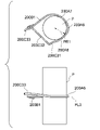
- FIG. 1A shows the staple 10 according to the first embodiment.
- FIG. 1B shows the staple 10 in the bound state.
- the staple 10 is formed of a flexible wire (for example, a metal wire such as iron).
- a holding object such as a plant stem or branch (hereinafter referred to as "stem or the like P") placed inside the staple 10
- stem or the like P a holding object
- both ends of the staple 10 are bent as shown in FIG. 1B to guide the staple.
- the guide element G can hold the stem or the like P.
- the wire rod forming the staple 10 may be a wire rod having both flexibility and plasticity.
- the staple 10 includes a main body portion 10A, a first leg portion 10B continuously extending from one end of the main body portion 10A, and a second leg portion 10C continuously extending from the other end.
- the main body portion 10A is a portion that connects the first leg portion 10B and the second leg portion 10C and surrounds the stem or the like P. As shown in FIG. 1B, in the bound state, the first leg portion 10B and the second leg portion 10C engage with the same guide element G, so that the main body portion 10A, the first leg portion 10B, and the second leg portion 10C are engaged. It is possible to arrange P such as a stem in the area surrounded by. Therefore, as long as the opening for arranging the stem or the like P is provided inside, the main body portion 10A is formed into various shapes such as a rectangle or a parallelogram according to the shape of the stem or the like P. Is possible. As shown in FIG.
- the main body portion 10A in the present embodiment is formed by being curved in a C-shape or an arc shape so as to open to the left of the paper surface.
- the direction (left side of the paper surface) from the closed side (right side of the paper surface) to the opening side (left side of the paper surface) of the main body portion 10A in FIG. 1A is referred to as the opening direction D1.
- the first leg portion 10B and the second leg portion 10C are portions for engaging with the guide element G.
- the first leg portion 10B is connected to one end portion 10A1 of the main body portion 10A, is bent and extends outward, and is further bent and opened from the first portion 10B1.
- a second portion 10B2 extending in direction D1 is provided.
- the first part 10B1 is an acute angle ⁇ 1 formed with the main body part 10A, that is, a bending angle of 90 degrees to approximately 90 degrees (for example, 80 degrees to 90 degrees).
- the second part 10B2 has an acute angle for engaging with the guide element G, and the angle formed with the first part 10B1, that is, the bending angle is 90 degrees to approximately 90 degrees (for example, 80 degrees to 90 degrees). It is an acute angle.
- the second portion 10B2 is offset outward with respect to the main body portion 10A and extends in the opening direction D1.
- first part 10B1 may be called the shoulder part. Further, since the first part 10B1 bends approximately 90 degrees with respect to the main body portion 10A and extends outward, and the second part 10B2 bends approximately 90 degrees with respect to the first part 10B1 and extends in the opening direction D1. A portion extending from one end of the main body portion 10A via the first portion 10B1 to the second portion 10B2 may be referred to as a crank portion.
- the first part 10B1 may be formed shorter than the second part 10B2 because the second part 10B2 may be offset. Since the second part 10B2 may have a length that can be engaged with the guide element G, it is preferable to form the second part 10B2 shorter than the third part 10C3 described later.
- the second leg portion 10C includes a third portion 10C3 that is connected to the other end portion 10A2 of the main body portion 10A and extends in the opening direction D1, and a fourth portion 10C4 that is bent outward from the tip portion of the third portion 10C3. ..
- the third part 10C3 is a part that closes the opening formed by the main body part 10A by being bent.
- the third portion 10C3 extends so as to extend in the opening direction D1, that is, substantially parallel to the second portion 10B2. Therefore, the third portion 10C3 is formed to be longer than the width of the opening formed by the main body portion 10A, that is, the distance between one end portion 10A1 and the other end portion 10A2 of the main body portion, and the second portion 10B2. It is preferably formed longer.
- the maximum inscribed circle C1 inscribed in the main body 10A corresponds to the size of the maximum stem or the like P expected to be held by the staple 10 without pushing the main body 10A.
- the third part 10C3 is formed longer than the shortest line segment connecting the two intersections where the tangent line T1 of the inscribed circle C1 intersects the second part 10B2 and the third part 10C3.
- the end portion of the third portion 10C3 can reach the second portion 10B2 without interfering with the inscribed circle C1, and the opening can be closed. ..
- the term "bendable" includes not only the case of being curved in a curved line as shown in FIG. 1B but also the case of being bent.
- the third part 10C3 is preferably formed longer than the shortest line segment connecting the two intersections where the tangent line T1 of the inscribed circle C1 intersects the second part 10B2 and the third part 10C3.
- the third part 10C3 may be formed shorter than the second part 10B2. That is, the third part 10C3 may have a length that reaches the second part 10B2, and can be selected to have an appropriate length according to the diameter of the stem or the like to be held.
- Part 4 10C4 (an example of a "bent part") is a part that engages with the guide element G.
- the fourth part 10C4 is bent outward (the side away from the opening) from the tip of the third part 10C3, while the third part 10C3 is bent in the direction (inside) of closing the opening (FIG. 1B). .. Since the bent third part 10C3 has elasticity in the direction of widening the closed opening and returning to the original position, the fourth part 10C4 is in the direction of widening the opening, that is, in the direction away from the first leg portion 10B. It is possible to apply tension to the guide element G. Therefore, it is possible to prevent the guide element G from bending and the staple 10 from falling off.
- the fourth part 10C4 is provided with an acute angle (bending angle) formed with the third part 10C3.
- the angle formed by the fourth part 10C4 and the third part 10C3 is preferably smaller than the angle formed by the first part 10B1 and the main body part 10A. With this configuration, the fourth part 10C4 can be suitably hooked on the guide element G.
- FIGS. 2A to 2E are schematic views showing a process of engaging the staple 10 with the guide element G using the binding machine 20.
- the line L1 in the figure is a reference line for facilitating comparison of changes in the positions of the staples 10 between the drawings.
- FIG. 2F is a schematic view showing how the tip of the second portion 10B2 of the first leg portion 10B is spirally curved as a result of advancing along the groove portion formed in the first deformed portion 20A.
- the binding machine 20 has a first deformed portion 20A (clincher portion) that bends or bends the tip end side of the first leg portion 10B (second portion 10B2) of the staple 10, and a first leg on the tip end side of the second leg portion 10C.
- the second deformed portion 20B that bends or bends the third portion 10C3 of the second leg portion 10C so as to move toward the tip end side of the portion 10B, and the extruded portion 20C for moving the staple 10 in the opening direction D1. Be prepared.
- the tip of the second deformed portion 10B2 surrounds the outer periphery of the guide element G.
- it can be composed of a spiral or arcuate groove formed so as to advance in a spiral on the outer periphery of the guide element G. Since the staple 10 has flexibility, when the staple 10 moves in the opening direction D1, the tip of the second portion 10B2 advances in the groove portion of the first deformed portion 20A while spirally bending.
- the outer periphery of the guide element G is moved around the guide element G as an axis. It becomes possible to form the tip of the first leg portion 10B of the staple 10 in a spiral shape surrounding the staple.
- the groove portion of the first deformed portion 20A is formed in a spiral shape or an arc shape so that the tip of the second portion 10B2 advances in a spiral shape on the outer circumference of the guide element G, but is not necessarily spiral or arcuate. It is not limited to the groove.
- the groove may be provided in a cylindrical shape having a top surface and a side surface.
- the top surface is provided with an inclined surface that advances in the axial direction as it advances in the circumferential direction.
- the tip of the first leg portion 10B that has penetrated into the groove portion having such a configuration travels in the circumferential direction and also travels in the axial direction along the inclined surface provided on the top surface, so that a spiral is drawn.
- the tip of the first leg portion 10B can be curved so as to draw a spiral even if the side surface has a cylindrical shape without a groove.
- the tip end side of the first leg portion 10B is provided with the guide element G. It can be curved so as to surround it.
- the first leg portion 10B of the staple 10 is preferably engaged with the guide element G. It will be possible to make it.
- the staple 10 and the guide element G are brought into close contact with each other so that the second part 10B2 of the staple 10 does not come off from the guide element G due to gravity, and the staple 10 is the guide element. It is preferable to bend or bend the staple 10 so that it is fixed to G.
- the second deformed portion 20B abuts on the second leg portion 10C and is on the tip end side of the first leg portion 10B.
- It can be composed of a guide portion 20B1 that bends in the direction toward the surface and a fulcrum portion 20B2 that abuts on the inside of the third portion 10C3 in order to function as a fulcrum when bending the second leg portion 10C.
- the third part 10C3 is formed longer than the second part 10B2. Therefore, by widening the distance between the guide portion 20B1 and the fulcrum portion 20B2, the guide portion 20B1 can apply a sufficient moment to the staple 10 to bend the staple 10.
- the binding machine 20 includes an extrusion portion 20C for moving the staple 10 in the opening direction D1.
- the extruded portion 20C has a linear cross section according to the shape of the main body portion extruded portion 20C1 formed according to the shape of the main body portion 10A (in this embodiment, formed in a curved shape according to the shape of the main body portion 10A) and the shape of the first portion 10B1.
- the shoulder extrusion portion 20C2 is provided so as to have.
- an example of the binding method will be described.
- the configuration of the binding machine is not limited to this disclosure. A known configuration may be utilized in which the staple 10 can be bent into a similar shape.
- FIG. 2A shows a state in which the staple 10 is attached to the binding machine 20. Since the staple 10 is not deformed in this state, it has the same configuration as shown in FIG. 1A.
- binding is started with the stem or the like P placed inside the staple 10 (the area surrounded by the main body 10A, the first leg 10B, and the second leg 10C).
- the stem or the like P and the guide element G are extended in substantially the same direction (vertical direction on the paper surface).
- FIG. 2B by moving the staple 10 in the opening direction D1 using the extrusion portion 20C, the tip of the opening direction D1 of the second leg portion 10C abuts on the guide portion 20B1, and the second leg portion 10C starts to bend. It shows the situation.
- the contact surface of the guide portion 20B1 with the second leg portion 10C is formed so as to have a portion that is inclined (inclined so as to approach the first leg portion 10B as it progresses in the opening direction D1). Will be done. Therefore, the tip end side of the second leg portion 10C that abuts on the guide portion 20B1 moves in the direction toward the tip end of the first leg portion 10B. At this time, the fulcrum portion 20B2 comes into contact with a predetermined portion inside the third portion 10C3. Therefore, the third portion 10C3 is curved in the direction toward the tip of the first leg portion 10B with the portion in contact with the fulcrum portion 20B2 as the fulcrum.
- the contact surface of the guide portion 20B1 with the second leg portion 10C is a substantially extending direction of the guide element G, and is an axial direction of the spiral groove portion formed in the first deformed portion 20A and is an opening direction. It is formed to have a portion (FIG. 3A) that is inclined in a direction perpendicular to D1 (hereinafter, referred to as "axial direction") (inclined so as to advance in the axial direction as it advances in the opening direction D1). Therefore, the tip end side of the second leg portion 10C moves in the direction toward the tip end of the first leg portion 10B, and at the same time, gently moves in the axial direction away from the plane including the main body portion 10A.
- the means for moving the tip end side of the second leg portion 10C toward the tip end of the first leg portion 10B and at the same time moving away from the plane including the main body portion 10A is not limited to the above. ..
- such means may be provided in the first deformation portion 20A.
- the first deformed portion 20A is provided with an inclined surface that inclines in a direction away from the plane including the main body portion 10A as it approaches the tip of the first leg portion 10B in the portion corresponding to the inclined surface 20AA in FIG. 3A.
- the inclined surface 20AA may be provided at a position where the tip end side of the second leg portion 10C abuts.
- the tip end side of the second leg portion 10C is moved toward the first leg portion 10B while being in contact with the inclined surface 20AA, so that the second leg portion 10C is moved in a direction closer to the first leg portion 10B. At the same time, it can be moved in the axial direction away from the plane including the main body portion 10A.
- the tip of the second portion 10B2 of the first leg portion 10B enters the groove portion of the first deformed portion 20A and starts bending by further moving the staple 10 in the opening direction D1 using the extrusion portion 20C.
- a guide element G is inserted through an opening hole formed in the axial direction (vertical direction on the paper surface). Therefore, the staple 10 is moved in the opening direction D1 with respect to the first deformed portion 20A, and as the tip of the second portion 10B2 enters the groove portion of the first deformed portion 20A, the guide element G is centered on the guide element G.
- the tip of the first leg portion 10B of the staple 10 can be deformed in a spiral shape surrounding the outer periphery of the staple 10.
- the connection portion between the third portion 10C3 and the fourth portion 10C4 abuts on the guide portion 20B1 at the beginning of the curvature, and then, as the curvature progresses, the fourth portion 10C4 becomes the guide portion. It is bent by coming into contact with 20B1. After that, as shown in the figure, the fourth portion 10C4 gets over the guide portion 20B1, so that the third portion 10C3 is bent by abutting on the guide portion 20B1. Since the curvature has progressed considerably at this point, the third part 10C3 and the fourth part 10C4 are close to the tip of the first leg portion 10B on which the guide element G is arranged.
- FIG. 2E shows a state in which the second leg portion 10C reaches the guide element G and the fourth portion 10C4 engages with the guide element G by further moving the staple 10 in the opening direction D1 using the extrusion portion 20C.
- FIG. 3A is a perspective view at this time.
- the opening of the main body portion 10A is closed in the cross-sectional view.
- the tip of the second leg portion 10C has the main body portion 10A and the first one with respect to the progress of bending. It travels axially away from the plane containing the legs 10B.
- the second leg portion 10C engages with the guide element G at a position separated from the portion where the first leg portion 10B engages with the guide element G.
- FIG. 3B shows a state in which a part of the part in which the groove portion of the first deformed portion 20A is formed is moved after the first leg portion 10B and the second leg portion 10C of the staple 10 are engaged with the guide element G, respectively.
- FIG. 4 is a perspective view showing how the stem or the like P is held by the guide element G by the staple 10.
- the first leg portion 10B is held or fixed to the guide element G by being wound around the guide element G.
- the second leg portion 10C is hooked on the guide element G and is movably locked to the guide element G.
- the fourth part 10C4 Since the third part 10C3 has elasticity in the direction of widening the closed opening and returning to the original position, the fourth part 10C4 has the guide element G in the direction of widening the opening, that is, in the direction away from the first leg portion 10B. It is possible to apply tension to the. Therefore, it is possible to suppress the possibility that the staple 10 will fall off from the guide element G because the guide element G is bent.
- the first part 10B1 is located closer to the axis of the second part 10B2 than the main body part 10A, for example, the first part 10B1 is pressed rather than pushing the main body part 10A.
- the person who pushes the force can efficiently transmit the force to the second part 10B2.
- the staple 10 according to the present embodiment has a stem because the connection portion between the main body portion 10A and the first portion 10B1 can be deformed in a direction of expanding the main body portion 10A with a relatively weak force by providing the first portion 10B1. It becomes possible to suppress the problem that hinders the growth of such P.
- the main body portion 10A to which the stem or the like P can come into contact during growth is curved, it is possible to suppress the problem that the stem or the like P is damaged by the main body portion 10A.
- the second part 10B2 and the third part 10C3 substantially in parallel, it is possible to suppress the problem that the adjacent staples 10 interfere with each other when the guide element G holds a plurality of adjacent stems or the like P. It will be possible.
- the staple 10 can hold or fix the first leg portion 10B to the guide element G and movably lock the second leg portion 10C to the guide element G.
- the second leg portion 10C can be easily removed from the guide element G. Further, as the stem or the like P grows, the staple 10 can be deformed in the stretching direction of the guide element G as well. Further, since the second part 10B2 is formed shorter than the third part 10C3, the second part 10B2 can be firmly held or fixed to the guide element G, while the third part 10C3 is the second part. Since it is formed longer than the portion 10B2, the second leg portion 10C can be easily removed from the guide element G with a slight movement. Therefore, it is possible to reduce the load on the operator at the time of harvesting the stem or the like, recovery after harvesting, disposal, and the like.
- the third portion 10C3 is formed longer than the width of the opening formed by the main body portion 10A, that is, the distance between one end portion 10A1 of the main body portion and the other end portion 10A2, the third portion 10C3 is formed by bending. It becomes possible to close the opening. Therefore, it is possible to reduce the possibility that the stem or the like P is detached from the staple 10.
- the bent third part 10C3 has elasticity in the direction of widening the closed opening and returning to the original position
- the fourth part 10C4 is in the direction of widening the opening, that is, in the direction away from the first leg portion 10B. It is possible to apply tension to the guide element G. Therefore, it is possible to reduce the possibility that the staple 10 will fall off from the guide element G as the guide element G bends.
- the fourth part 10C4 is locked to the guide element G by being bent counterclockwise (an example of the "first circumferential direction") about the guide element G.
- the second part 10B2 is curved or bent in the same counterclockwise direction (an example of the "first circumferential direction") so as to surround the guide element G with the guide element G as the center.
- the deformation of the two legs is performed at the same time. It is possible to move the staple 10 smoothly and bend it as compared with the above. Further, by forming the third part 10C3 longer than the second part 10B2, it is possible to easily make the timing of the deformation start of the two legs different.
- the means for engaging the first leg portion 10B with the guide element G is not limited to the method of bending and winding the second portion 10B2 around the guide element G.
- the second portion 10B2 of the first leg portion 10B may be bent at an acute angle to sandwich the guide element G. With such a configuration, the first leg portion 10B can be fixed to the guide element G by caulking.
- FIG. 5 is a schematic diagram showing a bound state of the staples 10 bound without using a binding machine.
- the guide element G is engaged with the bent portion so as to sandwich the guide element G from both sides.
- the first leg portion 10B and the second leg portion 10C can be suitably engaged with the guide element G.
- the tip end portion of the fourth part 10C4 may be further engaged with the first part 10B1 and the second part 10B2.
- the guide element G can be prevented from coming off from the bent portion by bending the angle ⁇ 1 (FIG. 1A) formed by the first portion 10B1 and the main body portion 10A so as to have an acute angle.
- the angle ⁇ 1 formed by the first portion 10B1 and the main body portion 10A is further reduced, the guide element G is sandwiched between the first portion 10B1 and the main body portion 10A, and the first leg portion 10B is used as the guide element G by caulking. It may be fixed. At that time, by gripping the long extending second portion 10B2, the first leg portion 10B can be easily plastically deformed and fixed to the guide element G. Further, even after the growth of the stem or the like P, the staple 10 can be easily removed from the guide element G by grasping the long extending second portion 10B2.
- FIG. 6A shows the staple 50 according to the second embodiment.
- FIG. 6B shows an example of the staple 50 in the bound state.
- the part understood by those skilled in the art to be the same as or similar to the description of the staple 10 according to the first embodiment will be omitted or simplified, and the description will be centered on different parts.
- the staple 50 includes a main body 50A, a first leg 50B continuously extending from one end 50A4 of the main body 50A, and a second leg 50C continuously extending from the other end 50A5.
- the main body portion 50A has a substantially U-shape or a U-shape with one opening (to the left of the paper surface), and has at least three contacts P1 to P3 circumscribing the virtual maximum inscribed circle C2.
- the main body portion 50A has a first side portion 50A1 extending in the tangential direction (opening direction) of the inscribed circle C2 at the first contact P1 on the first leg portion 50B side and a second contact P2 on the second leg portion 50C side.
- the second side portion 50A2 extending substantially parallel to the first side portion 50A1 in the tangential direction (opening direction) of the inscribed circle C2 in the above, the first side portion 50A1 and the second side portion 50A2 are connected, and the contact P1 and the contact point are contacted. It includes a third side portion 50A3 extending in the tangential direction of the inscribed circle C2 at the third contact point P3 with P2.
- the third side portion 50A3 in the present embodiment has an obtuse angle with the first side portion 50A1 and an acute angle with the second side portion 50A2.
- the angle ⁇ 2 formed by the third side portion 50A3 and the first side portion 50A1 is larger than 90 degrees
- the angle ⁇ 3 formed by the third side portion 50A3 and the second side portion 50A2 is smaller than 90 degrees. Therefore, the third side portion 50A3 is formed longer than the distance between one end portion 50A4 and the other end portion 50A5 of the main body portion 50A.
- the first leg portion 50B and the second leg portion 50C are portions for engaging with the guide element G.
- the first leg portion 50B includes a first portion 50B1 extending in the tangential direction of the inscribed circle C2 at the first contact point P1 from one end portion 50A4 of the main body portion 50A, that is, in the opening direction.
- a second part 50B2 that bends from the first part 50B1 and extends outward is provided. Since the second part 50B2 can have the same configuration as the first part 10B1, detailed description thereof will be omitted.
- the first leg portion 50B may be configured by omitting the first portion 50B1 and constituting only the second portion 50B2 that bends outward from one end portion 50A4 of the main body portion 50A.
- the third portion 50C3 is a portion that closes the opening formed by the main body portion 50A by being bent.
- the third portion 50C3 is formed by continuously extending to the second side portion 50A2 in the opening direction D1.
- the third portion 50C3 is more than the width of the opening formed by the body portion 50A, i.e., the distance between one end 50A4 and the other end 50A5 of the body. It is preferably formed long.
- the third portion 50C3 is formed longer than the third side portion 50A3.
- the staple 50 has four parallel sides including the first side portion 50A1, the second side portion 50A2, and the third side portion 50A3.
- the shape of this parallelogram is determined according to the bending position of the third part 50C3.
- the third side portion 50A3 forms the long side of the parallelogram
- the side including the first side portion 50A1 and the second side portion 50A2 forms the short side of the parallelogram. It is preferable to bend.
- the stem or the like P in the parallelogram grows, the stem or the like P is first brought into contact with the third side portion 50A3 or the third portion 50C3 corresponding to the long side that is more flexible. Will be possible. Therefore, it is possible to suppress the inhibition of the growth of the stem or the like P as compared with the case where the stem or the like P abuts on the short side which is hard to bend. In the figure, it is shown that the grown stem or the like P is in contact with the third side portion 50A3 and the third portion 50C3 first.
- the third side portion 50A3 may have a rectangular shape forming a right angle with the first side portion 50A1 and the second side portion 50A2, or may have an obtuse angle with the first side portion 50A1 and an acute angle with the second side portion 50A2. May be good.
- FIGS. 7A to 7D are schematic views showing a process of engaging the staple 50 with the guide element G using the binding machine 60.
- the staple 50 when viewed from a viewpoint parallel to the plane including the main body 50A is shown (the binding machine 60 is not shown).
- FIG. 7E is an enlarged cross-sectional view schematically showing how the second portion 50B2 of the staple 50 is bent and fixed to the guide element G by using the claw portion 60A1 of the binding machine 60.
- the staple 50 shown in FIG. 7A and the like is different from the staple 50 shown in FIG. 6A in that the second part 50B2 is bent more greatly.
- the angle formed by the straight line including the first side portion 50A1 (or the first portion 50B1) and the second portion 50B2 is 45 degrees or less.
- the same reference numerals are given here and detailed description thereof will be omitted.
- the binding machine 60 includes a claw portion 60A1 (FIG. 7E) for bending the second portion 50B2 of the staple 50, a guide element fixing portion 60A2 for fixing the second portion 50B2 to the guide element G, and a second portion of the staple 50.
- the second deformed portion 60B and the second leg portion 50C that move the tip end side of the second leg portion 50C of the staple 50 toward the tip end side of the first leg portion 50B by bending a predetermined portion of the two leg portions 50C.
- a third deformed portion 60C is provided to form a fourth portion 50C4 (bent portion) by bending a portion on the tip end side in a direction away from the first leg portion 50B.
- the claw portion 60A1 has a first leg in a state where the guide element G is sandwiched between the first portion 50B1 and the second portion 50B2 corresponding to the fixed side wire of the first leg portion 50B.
- the second portion 50B2 is pushed down to fix the first leg portion 50B to the guide element G.
- the claw portion 60A1 deforms the second portion 50B2 by applying an inclined load so that the second portion 50B2 does not collide with the fixed side wire 50B1 when the second portion 50B2 is pushed down.
- the guide element fixing portion 60A2 is provided with a groove-shaped portion surrounded by a bottom surface and two side surfaces in order to prevent the fixing side wire of the first leg portion 50B from moving.
- FIGS. 7A to 7E in order to clearly show the deformation and the positional relationship of the first leg portion 50B and the second leg portion 50C, for convenience, the bottom surface and the two side surfaces constituting the guide element fixing portion 60A2. Of these, one side surface provided on the front side of the paper is not shown.
- FIG. 7E shows how the guide element G is sandwiched between the first portion 50B1 and the second portion 50B2, which are fixed-side wires, and is deformed.
- the step of fixing the guide element G to the first leg portion 50B by the claw portion 60A1 is executed during the bending of the second leg portion 50C, but the present invention is not limited to this.
- the bending of the second leg portion 50C may be started.
- the second deformed portion 60B abuts on the outside of the portion on the tip end side of the second leg portion 50C, and loads the second leg portion 50C toward the tip end side of the first leg portion 50B. It includes a movable portion 60B1 that moves while hanging, and a fulcrum portion 60B2 that functions as a fulcrum for bending by abutting on the inside of a portion of the second leg portion 50C on the main body portion 50A side.
- the fulcrum portion 60B2 Since the fulcrum portion 60B2 is fixed until at least the bending angle becomes a required angle, it is possible to bend the second leg portion 50C with the portion abutting on the fulcrum portion 60B2 as the fulcrum as the movable portion 60B1 moves. It becomes.
- the fulcrum portion 60B2 may be fixed to the binding machine 60, or may be configured to be movable after bending.
- the third deformed portion 60C is composed of a wall portion that abuts inside the portion on the tip side of the movable portion 60B1. Since the third deformed portion 60C is fixed, the fourth leg portion 50C4 is formed by bending the region on the tip end side of the second leg portion 50C in the direction away from the first leg portion 50B as the movable portion 60B1 moves. It becomes possible to do.
- the configuration of the binding machine is not limited to this disclosure.
- a binding machine having another configuration capable of bending the staple 50 into a similar shape may be used.
- FIG. 7A shows an initial state in which the staple 50 is attached to the binding machine 60. Since the staple 50 is not deformed in this state, it has the same configuration as shown in FIG. 6A. Further, on the left side of the figure, it is shown that the main body portion 50A, the first leg portion 50B, and the second leg portion 50C are provided in the same plane PL.
- binding is started with the stem or the like P placed inside the staple 50 (the area surrounded by the main body 50A, the first leg 50B, and the second leg 50C).
- the stem or the like P and the guide element G are extended in substantially the same direction (vertical direction on the paper surface).
- the movable portion 60B1 is moved toward the tip end side of the first leg portion 50B while applying a load to the second leg portion 50C, so that the portion where the second leg portion 50C abuts on the fulcrum portion 60B2 is used as a fulcrum. It shows how the bending has started. Further, it shows how the region on the tip end side of the second leg portion 50C has started to bend in the direction away from the first leg portion 50B by the fixed third deformed portion 60C.
- the region on the tip end side of the second leg portion 50C passes through the gap between the movable portion 60B1 and the third deformed portion 60C, so that the tip end side of the second leg portion 50C is greatly bent to form the fourth leg portion 50C4.
- the region on the tip end side of the second leg portion 50C is deformed so as to be slightly returned by the springback, and then the shape as the fourth deformed portion 50C4 is determined. ..
- By adjusting the gap between the movable portion 60B1 and the third deforming portion 60C it is possible to adjust the angle of the fourth portion 50C4, which is suitable for hooking and locking the guide element G.
- the movable portion 60B1 also advances in the axial direction (normal direction of the plane PL) so as to be inclined with respect to the plane PL. Therefore, on the left side of FIG. 7B, it is shown that the tip of the second leg portion 50C has begun to be slightly separated from the plane PL.
- FIG. 7C shows the state of the staple 50 after the movable portion 60B1 is closest to the first leg portion 50B.
- the second leg portion 50C is bent until the fourth leg portion 50C4 passes through the guide element G, with the portion in contact with the fulcrum portion 60B2 as the fulcrum. In this embodiment, it is bent by 90 degrees or more.
- the tip of the second leg portion 50C intersects with the second portion 50B2. Further, as shown on the left side of the figure, the tip of the second leg portion 50C is largely separated from the plane PL.
- the claw portion 60A1 is bent by pressing the second portion 50B2 with the guide element G sandwiched between the fixed side wire of the first leg portion 50B and the second portion 50B2, thereby bending the first leg.
- the portion 50B is fixed to the guide element G.
- FIG. 7C it is shown that the end portion of the second portion 50B2 is separated from the plane PL as a result of the claw portion 60A1 pressing the second portion 50B2 so as to be inclined from the plane PL.
- FIG. 7D shows a state in which the bending load by the movable portion 60B1 is released and the fourth portion 50C4 is returned in the direction of the guide element G by the spring back.
- the guide element G is fixed by the first leg portion 50B and locked by the second leg portion 50C. It is preferable to adjust the bending amount of the second leg portion 50C by the movable portion 60B1 so that the guide element G is locked at the connection portion between the fourth portion 50C4 or the third portion 50C3 and the fourth portion 50C4.
- FIG. 8 is a schematic view showing how the staple 50 is deformed with the growth of P such as a stem.
- P such as a stem grows
- the staple 50 when the staples are formed in an arc shape, a large force is required to expand the staples in the radial direction. Therefore, the growth of P such as stems is inhibited.
- the staple 50 according to the present embodiment is formed in a quadrangular shape. Therefore, in many cases, the grown stem or the like P comes into contact with the vicinity of the center of either side. Since the vicinity of the center of the side is easily bent by a weak force, it is possible to suppress the inhibition of the growth of P such as a stem as compared with the case of an arcuate staple.
- the staple 50 is formed into a parallelogram having long sides. Therefore, the grown stem or the like P often comes into contact with the vicinity of the center of the long side. Since the vicinity of the center of the long side is easily bent by a weaker force than the vicinity of the center of the short side, it is possible to further suppress the inhibition of the growth of P such as a stem.
- the figure schematically shows how the third side portion 50A3 and the second leg portion 50C, which are the long sides, bend first when the stem or the like P grows to the size of the circle P10. Shows.
- the second leg portion 50C of the staple 50 is bent into a parallel four-sided shape that tilts to the left of the paper surface in the figure. Therefore, it is possible to reduce the angle ⁇ 4 at which the second leg portion 50C is bent as compared with the parallelogram inclined to the opposite side. Therefore, it becomes possible to quickly and easily perform the bending operation of the second leg portion 50C.
- the staple 50 according to the present embodiment can apply tension to the guide element G as the stem or the like P is deformed due to growth.
- FIG. 9A shows the shape of the staple 50 before the growth of the stem or the like P
- FIG. 9B shows the shape of the staple 50 when the stem or the like P grows and the staple 50 is expanded.
- the first leg 50B of the staple 50 holds the guide element G, but the second leg 50C holds the guide element G. It only locks the guide element G to the extent that it touches or does not touch.
- the staple 50 expands with the deformation of the stem or the like due to the growth of P.
- the first leg portion 50B of the staple 50 is locked to the guide element G by being bent counterclockwise (an example of the "first circumferential direction") in the figure around the guide element G.
- the second leg portion 50C is bent clockwise (an example of the "second circumferential direction”) about the guide element G.
- the staple 50 can be easily manufactured because the second leg portion 50C is linearly extended. Then, by using the binding method according to the present embodiment, it is possible to bend the second leg portion 50C and form the fourth portion (bending portion) 50C4 in one step. In addition, the same function and effect can be exhibited with respect to the portion having the same configuration as the staple according to the first embodiment.
- the staple 50 according to the second embodiment can be manually engaged with the guide element G, for example, without using a binding machine. That is, as in the schematic view showing the bound state of the staple 10 shown in FIG. 5, in the staple 50, since the connection portion between the first portion 50B1 and the second portion 50B2 is bent, the bent portion and the second leg By engaging the guide element G with the portion 50C so as to sandwich the guide element G from both sides, the first leg portion 50B and the second leg portion 50C can be suitably engaged with the guide element G.
- the angle formed by the first part 50B1 and the second part 50B2 is further reduced, the guide element G is sandwiched between the first part 50B1 and the second part 50B2, and the first leg part 50B is the guide element G by caulking. It may be fixed to.
- the present invention can be modified in various ways as long as it does not deviate from the gist thereof.
- some components in one embodiment may be added to other embodiments within the normal creative abilities of those skilled in the art.
- some components in one embodiment can be replaced with corresponding components in another embodiment.
- the curved main body portion 10A of the staple 10 may be replaced with the main body portion 50A of the staple 50.
- the main body portion of the staple 10 extends linearly in the opening direction, includes a first side portion including one end portion of the main body portion, and includes the other end portion of the main body portion, and is substantially parallel to the first side portion. It is provided with a second side portion extending in a straight line and a third side portion extending linearly by connecting the first side portion and the second side portion.
- the third side portion may have a rectangular shape forming a right angle with the first side portion and the second side portion, or may have an obtuse angle with the first side portion and an acute angle with the second side portion.
- the third side portion 50A3 of the staple 50 may be provided so as to form a substantially right angle with the first side portion 50A1 and the second side portion 50A2, respectively, or may have an acute angle with the first side portion 50A1 and the second side portion 50A1. It may be provided so as to form an acute angle with the portion 50A2.
- the second portion 50B2 of the staple 50 may be provided so as to be directly connected to the end portion 50A4 of the main body portion 50A, or may be provided with a portion extending in the opening direction D1 in between.
- the sides may be connected to each other by an arc or other curve at the corner of the main body.
- the main body may be formed by connecting a curved line and a straight line.
- the staple 50 may further include the second part 10B2 of the staple 10. In that case, the staple 50 further comprises a second portion that bends from the first portion and extends substantially parallel to the third portion.
- a binding machine may be used to bend the second part so as to hold the guide element G.
- Such a binding machine has a first deformed portion that bends or bends one end side of the wire, and a predetermined portion of the wire that bends or bends so that the other end side of the wire is directed toward one end. It may have a second deformed portion to be moved and a third deformed portion that bends or bends a portion closer to the tip side of the other than a predetermined portion to the outside.
- the second leg It is possible to bend or bend the second leg so as to move toward (toward the inside of the opening). At that time, by providing a fixed member such as the third deformed portion 60C at a position where the tip of the second leg abuts, the tip of the second leg is directed away from the first leg. It is also possible to bend (toward the outside of the opening) to provide a configuration corresponding to the bend.
- the tip end side of the first leg portion can be curved or bent so as to surround the guide element G.
- the second deformed portion of the binding machine is used to attach a predetermined portion of the second leg portion of the staple. It is curved or bent to move the tip side of the second leg toward the first leg, and is closer to the tip side of the second leg than a predetermined part by using the third deformed part of the binding machine. Perform the step of bending or bending the part outward to form a bent portion, and further surround the guide element with the first deformed portion of the binding machine around the tip end side of the second portion of the first leg of the staple. By bending or bending to, it is possible to perform the step of holding the guide element. Then, the formed bent portion can be locked to the guide element, and the step of applying tension to the guide element in the direction away from the first leg portion can be executed.
- the step of holding the guide element may be performed before the step of forming the bent portion.
- FIG. 10 shows a staple structure 500 composed of a plurality of staples 50 laminated so as to overlap each other and connected by an adhesive. As shown in this figure, by integrating a plurality of staples such as staples 10 or 50 and attaching them to a magazine or the like of a binding machine, it is possible to continuously perform a binding operation.
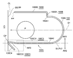
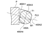
- FIG. 11A shows a staple 100 according to a modified example of the staple 10
- FIG. 11B shows an enlarged view of the region AR3 shown in FIG. 11A
- FIG. 11C shows a cross-sectional view of the staple 10 cut by a second plane PL2 described later.
- the points having the same configuration as the staple 10 according to the first embodiment will be given the same names, and the description will be omitted or simplified, and different parts will be mainly described.
- the staple 100 includes a main body 100A, a first leg 100B continuously extending from one end of the main body 100A, and a second leg 100C continuously extending from the other end. In common with.
- the main body portion 100A is a portion that connects the first leg portion 100B and the second leg portion 100C and surrounds the stem or the like P, and is formed from, for example, an arc having a central angle of 180 degrees.
- the P such as a stem, which is a held object, may be a growing plant such as a stem or a fruit, or may be a support or the like.
- the first leg portion 100B is a portion for engaging with the guide element G.
- the first leg portion 100B is connected to one end portion 100A1 of the main body portion 100A and is bent so as to extend to the outside of the opening.
- a unit 100B2 is provided.
- the portion extending from one end portion 100A1 of the main body portion 100A to the second portion 100B2 via the first portion 100B1, that is, the first portion 100B1 and the second portion 100B2 may be referred to as a crank portion.
- the first leg portion 100B includes a crank portion. Since the first leg portion 100B has the same configuration as the first leg portion 10B of the staple 10, detailed description thereof will be omitted.
- the opening direction D1 is the direction (left side of the paper surface) from the closed side of the main body 100A in FIG. 11A (the right side of the paper surface, for example, the midpoint of the main body 100A) to the opening side (left side of the paper surface). That is.
- the main body 100A By moving the main body 100A relative to the object to be held in the opening direction D1, the main body 100A can be arranged so as to surround the object to be held.
- the second leg portion 100C is bent by a binding machine or manually (manually by an operator) to close the opening of the main body portion 100A in a top view, and is engaged with the guide element G or the first leg portion 100B. It is a part for matching.
- the second leg portion 100C includes a third portion 100C3 that is connected to the other end portion 100A2 of the main body portion 100A and extends in the opening direction D1, and a fourth portion 100C4 that is bent outward from the tip portion of the third portion 100C3. Be prepared.
- the third part 100C3 is a part that closes the opening formed between one end 100A1 and the other end 100A2 of the main body 100A by bending at least in a plan view (FIG. 11A). Since the length of the third part 100C3 is the same as that of the third part 10C3 of the second leg portion 10C of the staple 10, detailed description thereof will be omitted. Therefore, the third portion 100C3 has a length that closes the opening of the main body portion 100A (that is, a length larger than the distance between the end portion 100A1 and the end portion 100A2 of the main body portion 100A that is separated in the direction perpendicular to the opening direction D1. Have). Further, as shown in FIG.
- the third part 100C3 is preferably formed longer than the second part 100B2.
- the first leg portion 100B is provided so as to be separated from the tangential plane TP that is in contact with the second leg portion 100C at the tip end in the opening direction D1.
- the third part 100C3 includes a fifth part 100C31 extending linearly from the end part 100A2 in the opening direction D1, a tip part corresponding to the tip of the third part 100C3, and a fifth part and a tip part. It has a sixth part located in between.
- the sixth part is provided so as to connect the tip portion and the fifth part 100C31, and is bent toward the first leg portion 100B side (inside the staple 10) with respect to the fifth part 100C31. Equivalent to. Therefore, the tip portion corresponding to the tip of the third portion 100C3 and the sixth portion are referred to as an end portion 100C32. It can be said that the end portion 100C32 is connected to the straight line portion 100C31 and corresponds to the tip portion of the second leg portion 100C on the opening direction D1 side.
- the straight line portion 100C31 is a portion that extends linearly substantially parallel to the opening direction D1.
- most of the third part 100C3 including the part in the direction opposite to the opening direction D1 corresponds to the straight part 100C31.
- the end portion 100C32 is a portion that is bent or curved in a direction approaching the first leg portion 100B with respect to the straight portion portion 100C31.
- the portion of the third portion 100C3 on the opening direction D1 side corresponds to the end portion 100C32.
- the contact CP with the 100C (end 100C32) is on the first plane PL1 (FIG. 12B, an example of the "first plane") that passes through the main body 100A, the first leg 100B, and the second leg 100C in the initial state.
- the first plane PL1 FIG. 12B, an example of the "first plane”
- the first leg portion 100B is provided.
- the end portion 100C32 is provided so as to be present in the region AR1.
- the straight line portion 100C31 includes a slightly deformed portion, the straight line SL passing through the center of the straight line portion 100C31 can be a straight line that approximates the line connecting the centers of the straight line portion 100C31.
- the end portion 100C32 since the end portion 100C32 is bent in a direction approaching the first leg portion 100B with respect to the straight portion 100C31, the end portion 100C32 of the second leg portion 100C advances in the opening direction D1. Displace to the first region AR1 side.
- the end portion 100C32 may be curved in a direction approaching the first leg portion 100B with respect to the straight portion portion 100C31.
- the fourth part 100C4 (an example of the "bending part") is a part for engaging with the guide element G or the first leg part 100B.
- the fourth part 100C4 is bent outward (the side away from the opening) from the end 100C32 of the third part 100C3 (more specifically, the tip connected to the tip of the end 100C32). Therefore, the fourth portion 100C4 is bent with respect to the end portion 100C32 so as to be displaced toward the second region AR2 where the first leg portion 100B is absent.
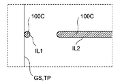
- the third portion 100C3 is provided so as to approach the first leg portion 100B at the tip portion in the opening direction D1. Therefore, as shown in FIG. 11C, there are at least two lines of intersection between the second plane PL2 (or the plane parallel to the second plane PL2 and passing through the outer edge of the straight line portion 100C31) and the surface of the second leg portion 100C. It is formed.
- the first line of intersection is the surface of the connecting portion between the third part 100C3 and the fourth part 100C4 and the second plane PL2 (or a plane parallel to the second plane PL2 and passing through the outer edge of the straight line portion 100C31). 1 line of intersection IL1.
- the second line of intersection is the second line of intersection IL2 between the surface of the portion including the straight line portion 100C31 and the second plane PL2 (or a plane parallel to the second plane PL2 and passing through the outer edge of the straight line portion 100C31).
- the second line of intersection IL2 is separated from the first line of intersection IL1 in the direction opposite to the opening direction D1 (in other words, the first line of intersection IL1 is separated from the second line of intersection IL2 in the opening direction D1).
- FIG. 11C shows a state in which the connection portion between the third portion 100C3 and the fourth portion 100C4 is slightly distorted by the wall surface GS immediately after the second leg portion 100C and the wall surface GS come into contact with each other at the contact CP.
- the second leg portion 100C is connected to the other end portion 100A2 of the main body portion 100A and is displaced in a direction approaching the straight portion 100C31 extending linearly in the opening direction D1 and the first leg portion 100B. It can also be said that it has an end portion 100C32 that is in contact with the contact plane TP at the contact point CP, and a fourth portion 100C4 that is bent outward from the end portion 100C32 and extends in the direction opposite to the opening direction D1.
- the inventors of the present application attempted a binding operation for holding the stem or the like P on the guide element G by engaging the staple 10 with the guide element G, the second leg portion 10C became the first leg. Focusing on the point that there is a possibility that the portion 10B does not bend in the direction of approaching the portion 10B. Therefore, the inventors have conceived a configuration in which the end portion 100C32 is provided on the second leg portion 100C. According to the staple 100, the second leg portion 100C is provided so that the contact CP exists in the first region AR1 where the first leg portion 100B is located. Therefore, when the staple 100 is moved in the opening direction D1, it is possible to induce the second leg portion 100C to bend in the direction approaching the first leg portion 100B as described below.
- FIG. 12A to 12H show the process of engaging the staple 100 with the guide element G using the binding machine 110 or manually from the upper surface (lower side of the paper in the figure) and the side surface (upper side of the paper in the figure). It is a schematic diagram which shows the state. That is, the staple 100 may be engaged with the guide element G by using the binding machine 110, or when the guide element G is made of a soft material such as gypsum board, the staple element 100 is manually engaged with the guide element G. May be good.
- the binding machine 110 includes an extrusion portion 110C for moving the staple 100 in a direction substantially coincide with the opening direction D1.
- the configuration of the binding machine is not limited to this disclosure.
- a binding machine having another configuration capable of moving the staple 100 in the opening direction D1 may be used.
- FIG. 12A shows an initial state in which the staple 100 is attached to the binding machine 110. Since the staple 100 is not deformed in this initial state, it has the same configuration as shown in FIGS. 11A to 11C. As shown in the figure, in the initial state, the main body portion 100A, the first leg portion 100B, and the second leg portion 100C of the staple 100 are provided on the first plane PL.
- binding is started with the stem or the like P placed inside the staple 100 (the area surrounded by the main body 100A, the first leg 100B, and the second leg 100C).
- the stem or the like P and the guide element G are extended in substantially the same direction (vertical direction on the paper surface).
- FIG. 12B by moving the staple 100 in the opening direction D1 using the extrusion portion 110C, the tip of the opening direction D1 of the second leg portion 100C abuts on the wall surface GS of the guide element G, and the second leg portion 100C is curved. It shows how it started.
- the first contact CP that abuts on the wall surface GS is the contact CP corresponding to the tip of the second leg 100C in the opening direction D1.
- the contact CP exists in the first region AR1 on the first leg 100B side of the second plane PL2 including the straight line SL. Therefore, as the second leg portion 100C advances in the opening direction D1 as shown in FIG. 12B, the end portion 100C32 that receives the force from the straight line portion 100C31 is bent in the direction approaching the first leg portion 100B.
- the first leg portion 100B is formed shorter than the second leg portion 100C, and is separated from the tangent plane TP in the initial state (FIG. 11A) without intersecting with the tangent plane TP. Therefore, the first leg portion 100B comes into contact with the wall surface GS after the second leg portion 100C starts contacting with the wall surface GS. Therefore, before being affected by the reaction caused by the contact of the first leg portion 100B with the wall surface GS, it is possible to induce the second leg portion 100C to bend in the direction of approaching the first leg portion 100B or in the direction of closing the opening. It will be possible.
- the first leg portion 100B engages with the guide element G by being pierced by the wall surface GS.
- the tip of the first leg 100B may be sharply formed to facilitate engagement with the guide element G.
- the second leg portion 100C further curves and approaches the first leg portion 100B, so that the top view is as shown in FIG. 12C.
- the second leg portion 100C (near the connection portion between the third portion 100C3 and the fourth portion 100C4) intersects the first leg portion 100B. Therefore, it is possible to close the opening provided in the main body 100A in the initial state in a top view.
- FIG. 12D shows a state in which the staple 100 is engaged with the guide element G.
- the first leg portion 100B may penetrate the guide element G.
- the fourth portion 100C4 of the second leg portion 100C is engaged with the first leg portion 100B by being hooked on the first leg portion 100B.
- the stem or the like P can be held by engaging the staple 100 with the guide element G while surrounding the stem or the like P. ..
- FIG. 12E shows, as a further modification, a holding state in which the main body 100A of the staple 100 is bent so as to be inclined with respect to the stretching direction of the stem or the like P.
- the first plane PL1 including the main body portion 100A is substantially perpendicular to the stretching direction of the stem or the like P.
- the staple 100 may be engaged with the guide element G in a state where the staple 100 is bent so that the plane including the main body 100A is inclined in the extending direction of the stem or the like P.
- the gap between the main body 100A and the stem or the like P may be non-uniform. Therefore, by bending the staple 100, it is possible to arrange the gap between the main body 100A and P such as a stem.
- the main body portion 100A can be easily bent as compared with the case where the second leg portion 100C is fixed to the guide element G.
- FIG. 12F shows an example of a holding state in which the fourth leg 100C4 is engaged with the first leg 100B by using the crank portion of the first leg 100B to hold the object to be held.
- the second leg 100C may be engaged with the first leg 100B by hooking the fourth leg 100C4 on the first leg 100B1 of the first leg 100B.
- FIG. 12G shows an example of a holding state in which the tip of the first leg portion 100B is bent to hold the held object.
- the first leg portion 100B is less likely to come off from the wall which is the guide element G.
- the second portion 100B2 of the first leg portion 100B may be formed longer than the third portion 100C3 of the second leg portion 100C.
- FIG. 12H not only the first leg portion 100B but also the fourth portion 100C4 of the second leg portion 100C is pierced into the wall surface GS of the guide element G so that the second leg portion 100C is engaged with the guide element G to be held.
- An example of the holding state in which is held is shown.
- a force acting in the direction of opening the opening acts on the fourth part 100C4 due to the elasticity of the curved third part 100C3. Therefore, when the fourth part 100C4 is pierced into the wall surface GS, it can be firmly engaged.
- the staple 100 according to this modification can also engage the staple 100 with the guide element G. Further, the second leg portion 100C can be reliably deformed in the direction approaching the first leg portion 100B.
- first leg portion 100B and the second leg portion 100C may both engage with the same guide element G, or the first leg portion 100B engages with the guide element G while the first leg portion 100B engages with the guide element G.
- the two leg portions 100C may engage with the first leg portion 100B instead of the guide element G.
- the first leg portion 100B may be formed with a sharp tip in order to facilitate engagement with the guide element G.
- the tip may be formed on the side of the second leg 100C with respect to the center line CL in which the apex PP passes through the center of the second leg 100B2 of the first leg 100B.
- the second part 100B2 can be easily bent in the direction opposite to the portion where P is located such as the stem. As a result, it is possible to prevent the linear portion of the second part 100B2 from being deformed or buckled toward the side where P is located, such as a stem. Further, even when binding using the staple 10 by the binding machine 20, the tip of the second portion 10B2 of the first leg portion 10B is at the tip of the center line CL where the apex PP passes through the center of the second portion 10B2. It may be formed on the side of the two legs 10C. By forming the apex PP of the tip in this way, it is possible to suitably bend or bend the tip side of the first leg portion 10B (second portion 10B2) of the staple 10 by the first deformed portion 20A (clincher portion). ..
- FIG. 13 shows a staple 120 according to a modified example of the staple 10.
- the points having the same configuration as the staple 10 according to the first embodiment will be given the same names, and the description will be omitted or simplified, and different parts will be mainly described.
- the staple 120 includes a main body 120A, a first leg 120B continuously extending from one end of the main body 120A, and a second leg 120C continuously extending from the other end. In common with.
- main body portion 120A has the same configuration as the main body portion 10A, the description thereof will be omitted.
- the first leg portion 120B is connected to one end portion 120A1 of the main body portion 120A and is bent outward to extend the first portion 120B1 and further bent from the first portion 120B1 to extend in the opening direction D1. To prepare for.
- the first part 10B1 of the staple 10 and the first part 120B1 of the staple 120 have different configurations.
- the first part 120B1 differs from the first part 10B1 having two bent parts in that it has four bent parts.
- the first portion 10B1 is bent to the end portion of the main body portion 10A to be connected to the portion that is bent outward to change the direction outward, and further bent to form the second portion 10B2. It has two bent parts, a connecting part.
- the first portion 120B1 bends and connects to the end portion 120A1 of the main body portion 120A so as to change its direction outward, and further bends and extends in the direction opposite to the opening direction D1. It has four bent parts: a portion that changes direction to a portion, a portion that is further bent and changes its direction outward again, and a portion that is further bent and connected to the second portion 120B2. Therefore, the first portion 120B1 has a first portion protruding in the opening direction D1 and a second portion connected to the first portion and protruding in the direction opposite to the opening direction D1.
- the configuration of the first part connecting the main body part 120A and the second part 120B2 extending in the opening direction D1 can be variously modified.
- the length of the portion extending in the direction opposite to the opening direction D1 may be increased as compared with the configuration of FIG.
- the first portion may be formed so as to connect to the second portion 120B2 so that the portion traveling outward and the portion traveling in the opening direction D1 are alternately repeated.
- the first portion may be formed so as to extend outward and in an inclined direction opposite to the opening direction D1 and connect to the second portion 120B2.
- This configuration corresponds to the configuration in which the bending angle ⁇ 1 is an acute angle (for example, 30 degrees to 60 degrees) in the configuration of the first part 10B1 shown in FIG. 1A.
- the staple 100 can be deformed in various ways.
- the main body 100A does not have to be an arc.
- different portions may be provided between the straight portion 100C31 and the end portion 100C32.
- a very short portion may be provided between the straight portion 100C31 and the end portion 100C32 so as to be temporarily displaced outward from the straight portion 100C31 and then connected to the end portion 100C32.
- different portions may be provided between the main body portion 100A and the straight portion 100C31.
- a very short portion may be provided between the main body portion 100A and the straight portion 100C31 so as to be gently curved to connect the two.
- those skilled in the art can modify the staples disclosed in the present application to the extent that the gist of the invention is not impaired.
- the inventors of the present application have found that, depending on the type of the stem P, the main body 50A bites into the stem P when the stem P grows and comes into contact with the staple 50. I paid attention to the point that there is a possibility that it will end up. Therefore, the inventors of the present application curved the end portion 200A1 so that an opening for inserting the stem or the like P, which is the object to be held, is provided between one end portion 200A1 and the other end portion 200A2. I came up with the configuration of the main body part 200A that connects the end part 200A2 and the end part 200A2.
- FIG. 14 schematically shows the staple 200.
- the staple 200 is connected to one end portion 200A1 and extends outward from the first portion 200B1 and the first portion 200B1 extending from the midpoint 200A3 of the main body portion 200A in the opening direction D1 toward the opening. It is provided with a first leg portion 200B having a second portion 200B2 bent in the shape of the second leg portion 200C and a second leg portion 200C having a third portion 200C3 connected to the other end portion 200A2 and extending in the opening direction D1.
- the first leg portion 200B may be configured by omitting the first portion 200B1 and comprising a second portion 200B2 that bends outward from one end portion 200A1 of the main body portion 200A.
- the main body portion 200A is a portion that surrounds the stem or the like P in a bound state (holding state) by inserting the stem or the like P and engaging the staple 200 with the guide element G.
- the main body portion 200A has the following configuration in addition to the configuration curved so as to be convex in the direction opposite to the opening direction D1.
- the opening direction D1 is a direction (left side of the paper surface) from the closed side (right side of the paper surface) of the main body 200A toward the opening side (left side of the paper surface).
- it can be said that it corresponds to the direction from the midpoint 200A3 of one end 200A1 and the other end 200A2 of the main body 200A toward the opening.
- the main body portion 200A is generally asymmetrically formed between the upper half of the paper surface and the lower half of the paper surface. More specifically, the main body 200A is curved from the vicinity of the midpoint 200A3 to the first main body 200A4 connected to one end 200A1, and curved from the vicinity of the midpoint 200A3 to the other end 200A2. It has a second main body 200A5 to be connected.
- the second main body portion 200A5 is virtually inscribed in the staple 200 at the intermediate portion including the midpoint 200A6 (an example of the "first position on the second main body portion") between the midpoint 200A3 and the other end 200A2. Separate from the inscribed circle C3.
- the inscribed circle C3 inscribed in the staple 200 is at least inscribed in, for example, one end 200A1 and the other end 200A2 of the staple 200.
- at least the intermediate portion including the midpoint 200A6 of the second main body portion 200A5 is formed so as to have a larger diameter than the circumference of the inscribed circle C3. Therefore, the midpoint 200A6 is formed by expanding the diameter so as to be separated from the inscribed circle C3 inscribed in the staple 200 at one end 200A1 and the other end 200A2 which are separated from the midpoint 200A6 with the midpoint 200A6 in between.
- the distance between the two is schematically drawn so as to be larger than usual.
- the staple 200 initially contacts a portion other than the midpoint 200A6 with the stem or the like P, and when the stem or the like P grows, it contacts the stem or the like P at the location including the midpoint 200A6. It is possible to make it. Since the midpoint 200A6 is formed by expanding the diameter, it is possible to suitably contact the grown and larger stems and the like P. The position where the grown stem or the like P is brought into contact may be a point other than the midpoint 200A6 of the second main body portion 200A5. Further, the inscribed circle may be inscribed in the staple 200 at a point other than the first end portion 200A1 and the second end portion 200A2.
- the first main body portion 200A4 includes an arc portion having a constant radius. Specifically, the first main body portion 200A4 follows an arc having a central angle of 90 degrees or less than 90 degrees of a circle (corresponding to the inscribed circle C3) whose diameter is the distance between the end portion 200A1 and the end portion 200A2. It is formed. Therefore, the first main body portion 200A4 is suitable for holding a stem or the like having a cross section smaller than the inscribed circle C3 or the inscribed circle C3.
- the second main body 200A5 is connected to the first main body 200A4 in the vicinity of the midpoint 200A3, and is connected to the second leg 200C at the other end 200A2, except in the vicinity of the midpoint 200A3 and the end 200A2. It is provided on the outside of the inscribed circle C3 between the spaces.
- the second main body portion 200A5 is formed in an elliptical arc having a semimajor axis larger than the radius of the inscribed circle C3. Therefore, the second main body portion 200A5 is separated from the inscribed circle C3 so that the distance from the virtual inscribed circle C3 increases as the distance from the midpoint 200A3 approaches the end portion 200A2, and further from the midpoint 200A3.
- the long axis LAX of the elliptical arc constituting the second main body portion 200A5 has the central CP3 of the inscribed circle C3 and the first portion 200B1 and the second portion of the first leg portion 200B. It is provided on a straight line L3 connecting the connection portion with the 200B2. Therefore, when the staple 200 is engaged with the guide element G near the connection portion between the first part 200B1 and the second part 200B2, the position farthest from the guide element G, the inscribed circle C3, and the second main body portion. The position where the maximum distance from 200A is located is near the midpoint 200A6.
- An elliptical arc is an arc when viewed from an inclined direction. Therefore, when at least a part of the second main body portion 200A5 has an elliptical arc, the portion of the elliptical arc can support the stem or the like P along the side surface of the columnar column. Therefore, it is possible to support the stem or the like P in a longer portion as compared with the case where the stem or the like P is supported by the arc. Therefore, it is possible to provide staples that are less likely to bite into P such as stems as compared with the conventional ones.
- the staple 200 is often used so as to incline 10 to 40 degrees with respect to the horizontal plane. Therefore, it is preferable that the elliptical arc provided in the second main body portion 200A5 is formed so that the inclination angle that becomes an arc when inclined with the short axis as the rotation axis is included in the range of 10 degrees or more and 40 degrees or less.
- the second main body 200A5 may have a different curve that approximates the elliptical arc instead of the elliptical arc.
- the second main body portion 200A5 may have an arc portion having a radius smaller than the radius of the inscribed circle C3.
- the second main body portion 200A may be formed so as to have an elliptical arc in a part thereof.
- a portion intersecting the straight line L3 may be formed from an elliptical arc, and the elliptical arc and the midpoint 200A3 and the end 200A2 may be connected by a smooth curve, respectively.
- the second main body portion 200A5 may be formed so as to be the farthest from the inscribed circle C3 at a portion other than the midpoint 200A6 of the second main body portion 200A5.
- the second main body portion 200A5 is formed so as to be the farthest from the inscribed circle C3. May be good.
- the connecting portion between the first portion 200B1 and the second portion 200B2 is in the opening direction D1 as compared with FIG. It will be the position where it has advanced to.
- the second main body portion 200A5 may be formed so as to be the farthest from the inscribed circle C3 at the position between the midpoint 200A6 and the midpoint 200A3.
- the first portion 200B1 of the first leg portion 200B is shortened in the opening direction D1 from the configuration shown in FIG. 14, from the inscribed circle C3 at the position between the midpoint 200A6 and the other end portion 200A2.
- the second main body portion 200A5 may be formed so as to be the farthest apart.
- the main body 200A as described above can be applied to staples other than staple 200.
- the configuration of the main body portion 200A described above may be applied to, for example, the staple 100 or the staple 120.
- the first main body portion 200A4 and the second main body portion 200A5 are asymmetrically formed.
- the portions corresponding to the first main body portion 200A4 and the second main body portion 200A5 of the main body portion 200A may be formed symmetrically, and have, for example, the same radius. It may be formed from an arc.
- a portion (or at least a part thereof) corresponding to the first main body portion 200A4 of the main body portion 200A is formed from an arc having a first radius, and the second main body portion 200A5 is formed.
- the corresponding portion may be formed from an arc having a second radius smaller than the first radius.
- the portions corresponding to the first main body portion 200A4 and the second main body portion 200A5 of the main body portion 200A may both be formed from an elliptical arc.
- an elliptical arc with the long axis LAX as the long axis may be connected to the end portion 200A1 and the end portion 200A2.
- the elliptical arc constituting the second main body 200A5 may extend to at least a part of the first main body 200A4.
- the third portion 200C3 is connected to the other end portion 200A2, and as it advances in the opening direction D1, it is outward, that is, a direction perpendicular to the opening direction D1 and away from the opening. It may have a curved portion 200C31 that bends so as to be displaced to the curved portion 200C31, and an extended portion 200C32 that bends and connects to the curved portion 200C31 and extends linearly in the opening direction D1.
- the connecting portion between the curved portion 200C31 and the extending portion 200C32 can be used as a fulcrum for bending the third portion 200C3. Therefore, the connecting portion between the curved portion 20C31 and the extending portion 200C32 may be referred to as a bent portion.
- the second leg portion 200C (the third part 200C3) can be easily bent by a binding machine or manually (manually by an operator). It becomes. Since the second leg portion (third portion) can be bent at a fixed position, the workability of the bundling work is improved.
- the second leg portion (third part) has elasticity due to the curved portion 200C31, the second leg portion (third part) is suppressed from biting into the stem or the like P, and the stem or the like P is reliably held. Is also possible.
- the curved portion 200C31 and the like as described above can be applied to staples other than staple 200.
- the configuration of the curved portion 200C31 or the like described above may be applied to, for example, the staple 50.
- the third portion 200C3 may have a tip bending portion 200C33 that is connected to the stretching portion 200C32 and is displaced outward as it advances in the opening direction D1.
- the second leg portion 200C when the second leg portion 200C (third part 200C3) is manually bent, the second leg portion 200C (third part 200C3) can be easily bent by pinching the tip bending portion 200C33. Therefore, the workability of the bundling work is improved.
- the staple 200 according to the present embodiment can support the stem or the like P at different portions due to the deformation of the stem or the like P due to the growth.
- FIG. 15A shows the posture of the staple 200 before the growth of the stem or the like P
- FIG. 15B shows the posture of the staple 200 after the stem or the like P has grown.
- the stem or the like P and the guide element G both extend from the lower side (vertical direction) to the upper side. Therefore, the lower view of FIGS. 15A and 15B corresponds to the side view, and the upper figure corresponds to the top view.
- the first leg portion 200B and the second leg portion 200C of the staple 200 are engaged with a guide element (not shown).
- the binding machine 60 (however, when the staple 200 has the tip bending portion 200C33, the binding machine 60 does not have to include the third deformation portion 60C).
- a binding machine may be used, or the binding work may be performed manually.
- the connecting portion between the first part 200B1 and the second part 200B2 of the first leg portion 200B is related to the guide element, as shown in FIG. 9A and the like. It fits. Further, the connecting portion between the tip bending portion 200C33 and the extending portion 200C32 of the second leg portion 200C also engages with the guide element. When the second leg portion 200C does not have the tip bending portion 200C33, the tip of the second leg portion 200C is manually bent and the second leg portion 200C is hooked on the guide element to guide the second leg portion 200C. It may be engaged with the element.
- the stems P are thin and do not come into contact with the staple 200.
- the stem or the like P gradually grows, a part of the stem or the like P eventually comes into contact with the staple 200, as shown in FIG. 15A.
- the plane PL3 including the main body portion 200A of the staple 200 (penetrating the main body portion 200A) maintains a state substantially perpendicular to the stretching direction of the stem or the like P.
- the flat surface PL3 in which the first leg portion 200B and the second leg portion 200C engage with the guide element and include the main body portion 200A (penetrates the main body portion 200A) with respect to the stretching direction of the stem or the like P is substantially defined.
- the posture of the staple 200 when it is vertical is called the first holding posture.
- the stem or the like P When the stem or the like P is located exactly in the center of the staple 200 and grows so as to have a circular cross section, the stem or the like P grows to the size of the virtual inscribed circle C3 in FIG. Inscribed in. However, in many cases, the stem or the like P is located off the center of the staple 200 and does not always grow so as to have a circular cross section. Therefore, as shown in FIG. 15A, the stem or the like P is an inscribed circle C3. It inscribes the staple 200 when it has a smaller cross section.
- the second main body portion 200A5 is formed by expanding the diameter so as to have a distance larger than the radius of the inscribed circle C3 from the center CP3 of the virtual inscribed circle C3. More specifically, the second main body portion 200A5 is formed including an elliptical arc having a semimajor axis larger than the radius of the inscribed circle C3 on the straight line L3. Therefore, in many cases, the staple 200 (before contacting the stem or the like P at the midpoint 200A6 which is the intersection of the straight line L3 and the second main body 200A5) has a contact point 200A7 (“first”) sandwiching the midpoint 200A6. It is inscribed with P such as a stem at two locations, one containing an example of a "point”) and the other containing a contact point 200A8 (an example of a "second point").
- the radius of the stem or the like P at this time is the radius PR1 (an example of the "first radius")
- the side surface of the stem or the like P has a cylindrical surface with the radius PR1. Therefore, the second main body portion 200A5 has a contact point 200A7 and a contact point 200A8 inscribed in the virtual cylindrical surface having a radius PR1 and a midpoint 200A6 located between the two contact points and separated from the virtual cylindrical surface ( It is formed to have an example of a "third point").
- the stem or the like P grows into a cylindrical shape having a radius PR2 larger than the radius PR1.
- the weight of the stem or the like P is applied to the staple 200 as it grows (including the case where a branch or the like extending horizontally from the stem or the like grows and leans on the staple 200 and the staple 200 is pushed down in the vertical direction).
- the main body since the vicinity of the first leg portion 200B is fixed to the guide element, as shown in FIG. 15B, the main body so that the portion including the second main body portion 200A5 which is not fixed to the guide element or the like is lowered in the vertical direction.
- the portion 200A is bent.
- the plane PL4 including the main body portion 200A (penetrating the main body portion 200A) is inclined with respect to the stretching direction of the stem or the like P.
- the second main body portion 200A5 includes a portion formed by an elliptical arc. Therefore, the portion of the elliptical arc of the second main body portion 200A5 including the midpoint 200A6 can support the stem or the like P along the side surface of the stem or the like P which is a cylindrical surface having a radius PR2.
- the extending direction of the stem or the like P is inclined with respect to the plane PL4 including the main body portion 200A (penetrating the main body portion 200A), and the midpoint 200A6 comes into contact with the stem or the like P.
- the posture of the staple 200 when the first leg portion 200B and the second leg portion 200C are engaged with the guide element in this state is referred to as a second holding posture.
- the staple 200 according to the present embodiment is not the first holding posture in which the main body portion 200A extends substantially in the horizontal direction, but the second holding posture in which the main body portion 200A is tilted with respect to the horizontal direction due to the weight from the object to be held. Focusing on the point that the staple 200 is more likely to bite into the object to be held in the posture, the main body portion 200A is configured to have an elliptical arc. With such a configuration, it is possible to secure a contact area with the cylindrical surface when the main body portion 200A is tilted, so that it is possible to suppress the staple 200 from biting into the object to be held.
- the staple 200 has elasticity due to the curved portion 200C31. Therefore, when the second leg portion (third portion) is bent at the bent portion and the stretched portion 200C32 comes into contact with the stem or the like P, it is possible to prevent the stretched portion 200C32 from biting into the stem or the like P.
- the inventors of this application also examined the cross-sectional structure of the staple that can suppress the bite of the staple. That is, when the staple has a circular cross section, the staple is likely to bite into the held object because it comes into contact with the held object at one point on the cross section. In addition, it may not be possible to engage the guide element with sufficient holding force. Therefore, we investigated the cross-sectional structure of the staple that can suppress the bite into the object to be held and strengthen the engagement with the guide element.
- the inventors of the present application have also conceived a configuration in which the shape of the inner surface that comes into contact with the held object and the outer surface that does not come into contact with the held object are different, and the cross section of the staple is asymmetrically formed.
- the inner surface of the staple that comes into contact with the object to be held is formed so as to increase the contact area with the held portion, while the outer surface of the staple that engages with the guide element is formed with the guide element.
- the cross-sectional structure of the staple will be described below.
- the cross-sectional structure of the staples shown in the present embodiment can be applied to any of the staples disclosed in the present application.
- the inventors of the present application have configured the vertical thickness of the staple as a configuration for increasing the contact area between the staple and the object to be held in the second holding posture while maintaining the same cross-sectional area as the conventional circular cross section.
- FIG. 16A shows an example of the staple 400A having such a configuration, and shows a cross-sectional view of the staple 400A cut in a cross section perpendicular to the stretching direction in the vicinity of the lower end portion when tilted by 15 degrees as the second holding posture. ..
- this staple 400A has a side portion 400A1 in which the left end portion of the paper surface corresponding to the inner side surface side extends linearly in the vertical direction in the same cross section, and the paper surface corresponding to the outer side surface side.
- the right end has a side portion 400A2 that extends linearly in the vertical direction.
- the end portion in the vertical direction is rounded and includes an upper end portion 400A3 and a lower end portion 400A4 that connect the upper ends and the lower ends of the side portions 400A1 and the side portions 400A2, respectively.
- the vertical direction means a direction perpendicular to the plane PL5 passing through the first leg portion, the second leg portion, and the main body portion
- the left-right direction means a direction parallel to the plane PL5.
- the plane PL5 is also tilted by 15 degrees with respect to the horizontal plane.
- the staple 400A has a thickness T1 in the vertical direction perpendicular to the plane PL5 and a width W1 in the left-right direction parallel to the plane PL5 in the same cross section.
- the thickness T1 is larger than the diameter D1 and the width W1 is smaller than the diameter D1 as compared with the diameter D1 of the virtual circle having the same cross-sectional area as the staple 400A.
- the inventors of the present application have a circular cross section when the surface of the stem or the like P is slightly moved toward the staple 400A so that the staple 400A bites into the surface of the stem or the like P which is the object to be held in the figure. It was confirmed that the contact area between the surface of P such as the stem and the staple 400A was larger than that of the staple 400A.
- the staple 400A having the cross section of FIG. 16A it is possible to increase the contact area between the staple and the object to be held as compared with the case having the circular cross section, and to suppress the biting of the staple. ..
- FIG. 16B shows an example of the staple 400B having such a configuration, and also shows a cross-sectional view of the staple 400B cut in a cross section perpendicular to the stretching direction in the vicinity of the lower end portion when tilted by 15 degrees as the second holding posture. ing.
- this staple 400B has two sides and an upper end portion and a lower end portion connecting them like the staple 400A, but the side portions, the upper end portion and the lower end portion are connected so as to be rounded. It is different from the staple 400A in which the side portion, the upper end portion and the lower end portion have an edge and are connected to each other.
- the same cross section has a thickness T2 in the vertical direction perpendicular to the plane PL5 and a width W2 in the left-right direction parallel to the plane PL5.
- the thickness T2 is larger than the diameter D1 and the width W2 is smaller than the diameter D1 as compared with the diameter D1 of the virtual circle having the same cross-sectional area as the staple 400B.
- the inner surface of the staple that comes into contact with the object to be held is formed so as to increase the contact area with the held portion, while the outer surface of the staple that engages with the guide element is formed with the guide element.
- Shown is a staple 400C having a configuration that is formed to increase the friction surface.
- the staple 400C has an elliptical arc portion whose inner side surface side has a major axis in the vertical direction and a straight line portion whose outer side surface side extends in the vertical direction in the cross section.
- the cross section includes an upper end portion connecting the upper end of the elliptical arc portion and the upper end of the straight line portion, and a lower end portion connecting the lower end portion of the elliptical arc portion and the lower end portion of the straight line portion.
- the straight portion extending in the vertical direction is lengthened by reducing the R (radius of curvature) connecting the upper end portion and the lower end portion and the straight portion as compared with the curvature of the elliptical arc portion.
- the staple 400C may have an inner side surface connected to at least one or both of the upper end portion and the lower end portion at an R of half or more of the thickness T3 in the cross section. Further, it may have an outer surface connected to at least one or both of the upper end portion and the lower end portion with an R of less than half of the thickness T3. Even with such a configuration, it is possible to lengthen the straight portion on the outer surface side, so that it is possible to increase the frictional resistance with the guide element such as a string. Further, since the contact area of the held object can be increased on the inner side surface side as compared with the case of the circular cross section, it is possible to suppress the biting into the held object.
- the same cross section has a thickness T3 in the vertical direction perpendicular to the plane PL5 and a width W3 in the left-right direction parallel to the plane PL5.
- the thickness T3 is larger than the diameter D1 and the width W3 is smaller than the diameter D1 as compared with the diameter D1 of the virtual circle having the same cross-sectional area as the staple 400C. It was confirmed that even in such a staple 400B, the contact area between the surface of P such as a stem and the staple 400B is larger than that in the case of a circular cross section. Further, by providing the straight portion on the outside, it is possible to increase the friction surface with the guide element and to strengthen the engagement with the guide element.
- staples having the cross section shown in the present embodiment it is possible to suppress the biting of the held object and provide the staple that does not easily come off from the guide element.
- Other staples disclosed in this application can be variously modified by demonstrating the ordinary creative ability of those skilled in the art.
- staples may have parts between one part and another that are not described in this application and perform different functions.
- the configuration shown in one embodiment may be applied to the configuration shown in another embodiment.
- the cross-sectional configuration shown in the fourth embodiment may be provided to the staple shown in the first embodiment.
- a staple made of flexible wire that can hold plant stems and branches on the guide element The main body that opens on one side and A first leg that continuously extends from one end of the main body on the opening side, It is provided with a second leg portion that extends continuously from the other end of the main body portion on the opening side.
- the first leg portion has a first portion that bends and extends outward, and a second portion that bends from the first portion and extends in the opening direction.
- the second leg portion has a third portion extending in the opening direction and a fourth portion bent outward from the tip portion of the third portion.
- the third part is a staple formed longer than the second part.
- the staple according to (9), wherein the third side portion has an obtuse angle with the first side portion and an acute angle with the second side portion.
- the main body that opens on one side and A first leg that continuously extends from one end of the main body on the opening side, It is provided with a second leg portion that extends continuously from the other end of the main body portion on the opening side.
- the first leg portion has a first portion that bends and extends outward.
- the second leg portion has a third portion extending in the opening direction.
- the main body is It has at least three contacts circumscribing the virtual inscribed circle, and further The first side portion extending in the tangential direction of the inscribed circle at the first contact point on the first leg portion side, A second side portion extending substantially parallel to the first side portion in the tangential direction of the inscribed circle at the second contact point on the second leg portion side.
- a staple comprising the first contact and a third side extending in the tangential direction of the inscribed circle at the third contact between the second contact.
- the third side portion has an obtuse angle with the first side portion and an acute angle with the second side portion.
- the staple according to (11) which is formed to be longer than the distance between the one end of the main body and the other end.
- (13) The staple according to (11) or (12), wherein the first leg portion further includes a second portion that bends from the first portion and extends substantially parallel to the third portion.
- It is a staple that can hold the stems and branches of plants in the guide element by being deformed by a binding machine that has a deforming part.
- Consists of flexible wire The main body that opens on one side and A first leg that continuously extends from one end of the main body on the opening side, It comprises a second leg portion having a bend portion that extends continuously from the other end of the main body portion on the opening side and is bent outward on the distal end side.
- the first leg portion is bent or bent so as to have a first portion that bends and extends outward, and a first portion that bends from the first portion and extends in the opening direction, and the tip end side surrounds the guide element with the first deformed portion.
- the guide element is provided with a second part configured to be able to hold the guide element.
- the second leg portion extends in the opening direction and is curved or bent at the second deformed portion, so that the bent portion is bent in a state where the stem or branch of the plant is positioned inside the staple.
- a plant stem or branch can be used as a guide element by being deformed by a binding machine having a deformed portion and a third deformed portion that bends or bends a portion closer to the other tip side than the predetermined portion to the outside. It is a staple that can hold such things as Consists of flexible wire
- the first leg portion has a first portion that bends and extends outward, and a second portion that bends from the first portion and extends in the opening direction, and the tip end side is the first deformation portion and the guide element.
- the second leg portion extends in the opening direction and is curved or bent inward in the second deformed portion, and the second leg portion extends in the opening direction and is curved outward in the third deformed portion.
- it is provided with a fourth part that is configured to be lockable to the guide element in a state where the stem or branch of the plant is positioned inside the staple by being bent. Staples.
- the main body that opens on one side and A first leg that continuously extends from one end of the main body on the opening side, A second leg that continuously extends from the other end of the main body on the opening side, Equipped with The first leg portion has a first portion that bends and extends outward, and a second portion that bends from the first portion and extends in the opening direction.
- the second leg has a staple having a third portion extending in the opening direction and a fourth portion bent outward from the tip portion of the third portion.
- the first deformed part that bends or bends one end side of the wire A step of attaching to a binding machine including a second deforming portion that bends or bends a predetermined portion of the wire rod and moves the other end side of the wire rod toward the one end side.
- the stem, branch, etc. positioned in the area surrounded by the first leg, the second leg, and the main body, the second leg of the binding machine is used.
- Bundling method including. (17) It is a binding method that allows the guide element to hold the stems and branches of the plant.
- Consists of flexible wire The main body that opens on one side and A first leg that continuously extends from one end of the main body on the opening side, It is provided with a second leg portion that continuously extends in the opening direction from the other end of the main body portion on the opening side.
- the first leg portion is a staple having a first portion that bends and extends outward, and a second portion that bends from the first portion and extends in the opening direction.
- the first deformed part that bends or bends one end side of the wire A second deformed portion that bends or bends a predetermined portion of the wire rod to move the other end end side of the wire rod toward the one end end side.
- the predetermined portion of the second leg portion is curved or bent to move the tip end side of the second leg portion in the direction toward the first leg portion, and the third deformed portion of the binding machine is used.
- Bundling method including.
- the step of bending or bending so as to surround the guide element is The tip end side of the first leg is curved or bent in the first circumferential direction around the guide element so as to surround the guide element.
- the step of locking the bent portion to the guide element is The binding method according to (16), wherein the fourth portion bent in the first circumferential direction around the guide element is locked to the guide element.
- the step of bending or bending so as to surround the guide element is The tip end side of the first leg is curved or bent in the second circumferential direction around the guide element so as to surround the guide element.
- the step of locking the fourth part to the guide element is The binding method according to (17), wherein the bent portion bent in the first circumferential direction opposite to the second circumferential direction around the guide element is locked to the guide element.
- the step of moving the tip end side of the second leg portion in the direction toward the first leg portion is The tip end side of the second leg portion is moved in a direction toward the first leg portion while being moved in a direction away from the plane including the main body portion.
- the main body which is curved and one side opens, A first leg that continuously extends from one end of the main body on the opening side, It is provided with a second leg portion that extends continuously from the other end of the main body portion on the opening side.
- the first leg portion extends linearly in a direction of bending and extending to the outside of the opening and bending from the first portion to close the opening so as to surround the guide element on the distal end side.
- the second leg portion is bent outward from the tip portion of the third portion and the third portion including a portion that is bent and extends linearly in a direction to close the opening, so that the second leg portion can be bent outward from the first leg portion.
- the main body A first leg portion that extends continuously from one end of the main body portion, It is provided with a second leg portion that extends continuously from the other end of the main body portion.
- the first leg portion has a second portion that extends linearly in a direction that closes the opening and holds the guide element by being curved or bent so as to surround the guide element on the distal end side.
- the second leg portion is bent outward from the tip portion of the third portion and the third portion including a portion that is bent and extends linearly in a direction to close the opening, so that the second leg portion can be bent outward from the first leg portion.
- the main body has a first side extending linearly from the first leg, a second side extending linearly from the second leg substantially parallel to the first side, and the first side.
- a staple having an obtuse angle with the portion and a third side portion connected to the second side portion at an acute angle.
- the third portion has a fifth portion extending linearly in the opening direction and a sixth portion located between the fifth portion and the tip portion.
- the staple according to any one of (1) to (10), wherein the sixth part is bent toward the first leg portion with respect to the fifth part.
- the third portion has a straight portion extending linearly in the opening direction and the tip portion.
- the contact point between the tangential plane in contact with the second leg and the second leg, which is perpendicular to the straight line passing through the center of the straight portion, is Of the two regions perpendicular to the first plane passing through the first leg portion and the second leg portion and partitioned by the second plane including the straight line, the first leg portion is located.
- the staple according to any one of (1) to (10) existing in the region. (25)
- the portion including the tip portion is bent with respect to the straight portion so as to be displaced toward the first region side.
- the fourth portion is bent with respect to a portion including the tip portion of the two regions partitioned by the second plane so as to be displaced toward the second region without the first leg portion (24). ).
- the main body is a first main body that curves from the vicinity of the midpoint and connects to one end, and a second main body that curves from the vicinity of the midpoint and connects to the other end.
- the second main body is from a virtual inscribed circle inscribed in the staple at at least two contacts spaced apart from the first position across the first position at the first position on the second main body. Separation The staple according to (28). (30) The virtual inscribed circle inscribes the staple at at least one of the ends and the other end, and the first main body has an arc portion having an arc having the same radius as the inscribed circle. death, The staple according to (29), wherein the second main body portion has an elliptical arc portion having a semimajor axis larger than the radius of the inscribed circle.
- the thickness of the staple in the vertical direction perpendicular to the first plane passing through the first leg, the second leg, and the main body is the diameter of a virtual circle having the same cross section as the cross section of the staple. Larger, The width of the staple in the left-right direction parallel to the first plane passing through the first leg and the second leg is smaller than the diameter of the virtual circle having the same cross-sectional area as the cross-sectional area of the staple.
- the staple according to any one of (28) to (33). (35) It is made of flexible wire and is a staple for the guide element to hold an object to be held such as a plant stem or branch.
- a body portion having a curved portion that is curved so that an opening for inserting the held object is provided between the two ends and connects the one end portion and the other end portion.
- a first leg that connects to one end of the body and engages with the guide element. It comprises a second leg that connects to the other end of the body and engages with the guide element.
- the main body portion has a central axis perpendicular to a first plane passing through the first leg portion and the second leg portion, has a first radius, and is formed on a virtual first cylindrical surface inscribed in the staple. It has a first point inscribed, a second point inscribed in the first cylindrical surface, and a third point located between the first point and the second point and separated from the first cylindrical surface.
- the staple is The first leg portion and the second leg portion engage with the guide element so as to surround the held object in a state where the extending direction of the held object is substantially perpendicular to the plane including the main body portion. 1 holding posture and When the main body portion is bent by the grown object to be held, the stretching direction of the held object is inclined with respect to the plane including the main body portion, and the third point is in contact with the held object.
- a staple configured to surround the object to be held so that the first leg and the second leg can take a second holding posture in which the guide element is engaged.
Abstract
Description
図1Aは、第1実施形態に係るステープル10を示す。図1Bは、結束状態におけるステープル10を示す。このステープル10は、可撓性を有する線材(例えば、鉄等の金属の線材)から形成される。このステープル10の内部に植物の茎や枝などの被保持物(以下、「茎等P」という。)を配置した状態で、図1Bに示されるようにステープル10の両端部を折り曲げて、ガイド要素Gに係合することにより、ガイド要素Gに茎等Pを保持させることが可能となる。なお、ステープル10を形成する線材は、可撓性とともに可塑性を有する線材であってもよい。
以下、結束機20を用いたステープル10の結束方法について説明する。図2A乃至図2Eは、結束機20を用いてステープル10をガイド要素Gに係合させるプロセスを示す模式図である。なお、同図における線L1は、図面間におけるステープル10の位置の変化の比較を容易にするための基準線である。図2Fは、第1脚部10Bの第2部10B2の先端が、第1変形部20Aに形成された溝部に沿って進行した結果、螺旋状に湾曲する様子を示す模式図である。
以下、結束方法の一例を説明する。但し、結束機の構成は、本開示に限られるものではない。ステープル10を同様の形状に折り曲げることが可能な知られた構成を利用してもよい。
第1実施形態に係るステープル10は、結束機を用いることなく例えば手動でガイド要素Gに係合させることも可能である。図5は、結束機を用いることなく結束されたステープル10の結束状態を示す模式図である。
図6Aは、第2実施形態に係るステープル50を示す。図6Bは、結束状態におけるステープル50の一例を示す。なお第1実施形態に係るステープル10に関する説明と同一又は類似することが当業者によって理解される部分については、説明を省略乃至簡略化し、異なる部分を中心に説明する。
続いて、結束機60を用いたステープル50の結束方法について説明する。図7A乃至図7Dは、結束機60を用いてステープル50をガイド要素Gに係合させるプロセスを示す模式図である。各図の左側には、本体部50Aを含む平面に平行な視点で見たときのステープル50が示されている(結束機60は不図示)。また、図7Eは、結束機60の爪部60A1を用いて、ステープル50の第2部50B2が屈曲されてガイド要素Gに固定される様子を模式的に示す拡大断面図である。
第2実施形態に係るステープル50は、結束機を用いることなく例えば手動でガイド要素Gに係合させることも可能である。すなわち、図5に示されるステープル10の結束状態を示す模式図と同様に、ステープル50は、第1部50B1と第2部50B2との接続部は屈曲されるため、この屈曲部と第2脚部50Cとでガイド要素Gを両側から挟みこむように係合することによって、第1脚部50Bと第2脚部50Cを好適にガイド要素Gに係合することが可能になる。
本発明は、その要旨を逸脱しない限り、さまざまな変形が可能である。たとえば、当業者の通常の創作能力の範囲内で、ある実施形態における一部の構成要素を、他の実施形態に追加することができる。また、ある実施形態における一部の構成要素を、他の実施形態の対応する構成要素と置換することができる。
以下第1実施形態に係るステープル10の第1変形例について説明する。
第6部は、先端部と第5部100C31との間に両者を接続するように設けられ、第5部100C31に対して第1脚部100B側(ステープル10の内側)に屈曲される部分に相当する。このため第3部100C3の先端に相当する先端部と第6部を端部100C32と呼ぶ。端部100C32は、直線部100C31に接続し、第2脚部100Cの開口方向D1側の先端の部分に相当するとも言える。
以下ステープル100の結束方法について説明する。図12A乃至図12Hは、結束機110を用いて、又は、手作業によりステープル100をガイド要素Gに係合させるプロセスを上面(同図の紙面下方)及び側面(同図の紙面上方)から見た様子を示す模式図である。即ちステープル100は、結束機110を用いてガイド要素Gに係合させてもよいし、ガイド要素Gが石膏ボード等、柔らかい材質から構成されている場合、手動でガイド要素Gに係合させてもよい。
ここで第1脚部100Bは、ガイド要素Gへの係合を容易にするために、先端が鋭利に形成されてもよい。先端は、頂点PPが第1脚部100Bの第2部100B2の中心を通過する中心線CLよりも第2脚部100Cの側に形成されてもよい。先端の頂点PPをこのように形成することで、第2部100B2が茎等Pの位置する部位と反対側の方向へたわみ易くすることができる。これにより、第2部100B2の直線形状を成している部位が、茎等Pの位置する側へ変形したり、座屈したりすることを抑制できる。
更に結束機20によりステープル10を用いて結束する場合であっても、第1脚部10Bの第2部10B2の先端を、頂点PPが第2部10B2の中心を通過する中心線CLよりも第2脚部10Cの側に形成されてもよい。先端の頂点PPをこのように形成することで、ステープル10の第1脚部10B(第2部10B2)の先端側を第1変形部20A(クリンチャ部)で湾曲又は屈曲させることを好適に行える。
以下第1実施形態に係るステープル10の第2変形例について説明する。
以下、第3実施形態に係るステープル200について説明する。
本体部200Aは、茎等Pを挿入してステープル200をガイド要素Gに係合することにより、結束状態(保持状態)において茎等Pを囲む部分である。
続いて第2脚部200Cの第3部200C3に設けられた湾曲部の構成について説明する。
続いて第2脚部200Cの第3部200C3に設けられた先端曲げ部の構成について説明する。
[第4実施形態]
なおステープル400Cは、断面において、厚みT3の半分以上のRで上端部又は下端部の少なくとも一方又は双方と接続される内側面を備えてよい。また、厚みT3の半分未満のRで上端部又は下端部の少なくとも一方又は双方と接続される外側面とを有してもよい。このような構成によっても外側面側のストレート部を長くすることが可能となるから紐等のガイド要素との摩擦抵抗を高めることが可能となる。また内側面側において円断面の場合と比較して被保持物の接触面積を大きくすることが可能となから被保持物への食い込みを抑制することが可能となる。
このようなステープル400Bにおいても、円形断面の場合と比較して、茎等Pの表面とステープル400Bとの接触面積が大きくなることを確認した。また、外側に直線部を設けることにより、ガイド要素との摩擦面を増加し、ひいてはガイド要素との係合を強めることも可能となる。
以上のとおりであるから本実施形態に示される断面を有するステープルを採用することにより、被保持物の食い込みを抑制し、ガイド要素から外れにくいステープルを提供することが可能となる。
その他本出願に開示されるステープルは、当業者の通常の創作能力の発揮により種々変形可能である。例えばステープルは、ある部分と他の部分との間に、異なる機能を発揮する本出願に記載されていない部分を有していてもよい。またある実施形態に示される構成を、他の実施形態に示される構成に適用させてもよい。例えば第4実施形態に示される断面構成を第1実施形態に示されるステープルに提供させてもよい。
可撓性を有する線材からなり、ガイド要素に植物の茎や枝などを保持可能なステープルであって、
一方が開口する本体部と、
前記本体部の前記開口側の一方の端部から連続して延びる第1脚部と、
前記本体部の前記開口側の他方の端部から連続して延びる第2脚部と
を備え、
前記第1脚部は、屈曲して外側に延びる第1部と、前記第1部から屈曲して前記開口方向に延びる第2部とを有し、
前記第2脚部は、前記開口方向に延びる第3部と、前記第3部の先端部から外側に曲げられる第4部とを有し、
前記第3部は前記第2部よりも長く形成される
ステープル。
(2)
前記第3部は、前記本体部の前記一方の端部と前記他方の端部との距離よりも長く形成される(1)に記載のステープル。
(3)
前記第2部と前記第3部とは、略平行に形成される(1)に記載のステープル。
(4)
前記第1部は、前記本体部とのなす角が鋭角である(1)~(3)の何れか一つに記載のステープル。
(5)
前記第1部と前記本体部とのなす角が90度又はほぼ90度である(4)に記載のステープル。
(6)
前記本体部は、C字状に湾曲して形成される部分を備える(1)~(5)の何れか一つに記載のステープル。
(7)
前記本体部は、矩形状に形成される部分を備える(1)~(5)の何れか一つに記載のステープル。
(8)
前記本体部は、平行四辺形状に形成される部分を備える(1)~(5)の何れか一つに記載のステープル。
(9)
前記本体部は、前記開口方向に直線状に延び、前記一方の端部を含む第1辺部と、前記他方の端部を含み、前記第1辺部と略平行に延びる第2辺部と、前記第1辺部と前記第2辺部を接続し直線状に延びる第3辺部とを備える(1)~(5)の何れか一つに記載のステープル。
(10)
前記第3辺部は、前記第1辺部と鈍角をなし、前記第2辺部と鋭角をなす(9)に記載のステープル。
(11)
可撓性を有する線材からなり、ガイド要素に植物の茎や枝などを保持可能なステープルであって、
一方が開口する本体部と、
前記本体部の前記開口側の一方の端部から連続して延びる第1脚部と、
前記本体部の前記開口側の他方の端部から連続して延びる第2脚部と
を備え、
前記第1脚部は、屈曲して外側に延びる第1部を有し、
前記第2脚部は、前記開口方向に延びる第3部を有し、
前記本体部は、
仮想的な内接円に外接する少なくとも3つの接点を有し、更に、
前記第1脚部側の第1の前記接点における前記内接円の接線方向に延びる第1辺部と、
前記第2脚部側の第2の前記接点における前記内接円の接線方向に、前記第1辺部に略平行に延びる第2辺部と、
前記第1の接点と、前記第2の接点との間の第3の前記接点における前記内接円の接線方向に延びる第3辺部とを備えるステープル。
(12)
前記第3辺部は、前記第1辺部と鈍角をなし、前記第2辺部と鋭角をなし、
前記本体部の前記一方の端部と前記他方の端部との距離よりも長く形成される(11)に記載のステープル。
(13)
前記第1脚部は、前記第1部から屈曲して前記第3部に略平行に延びる第2部を更に備える(11)又は(12)に記載のステープル。
(14)
線材の一方の先端側を湾曲又は屈曲させる第1変形部と、前記線材の所定の部位を湾曲又は屈曲させて、前記線材の他方の先端側を前記一方の先端側に向けて移動させる第2変形部とを有する結束機により変形されることで、ガイド要素に植物の茎や枝などを保持可能なステープルであって、
可撓性を有する線材からなり、
一方が開口する本体部と、
前記本体部の前記開口側の一方の端部から連続して延びる第1脚部と、
前記本体部の前記開口側の他方の端部から連続して延び、先端側において外側に曲げられる屈曲部を有する第2脚部と
を備え、
前記第1脚部は、屈曲して外側に延びる第1部と、前記第1部から屈曲して前記開口方向に延び、先端側が前記第1変形部で前記ガイド要素を囲むように湾曲又は屈曲されることで、前記ガイド要素を保持可能に構成される第2部とを備え、
前記第2脚部は、前記開口方向に延び前記第2変形部で湾曲又は屈曲されることで、前記ステープルの内側に前記植物の茎や枝などを位置させた状態で、前記屈曲部を前記ガイド要素に係止可能に構成される第3部を備える、
ステープル。
(15)
線材の一方の先端側を湾曲又は屈曲させる第1変形部と、前記線材の所定の部位を湾曲又は屈曲させて、前記線材の他方の先端側を前記一方の先端側に向けて移動させる第2変形部と、前記所定の部位よりも前記他方の先端側に近い部位を外側に湾曲又は屈曲させる第3変形部と、を有する結束機により変形されることで、ガイド要素に植物の茎や枝などを保持可能なステープルであって、
可撓性を有する線材からなり、
一方が開口する本体部と、
前記本体部の前記開口側の一方の端部から連続して延びる第1脚部と、
前記本体部の前記開口側の他方の端部から連続して延びる第2脚部と
を備え、
前記第1脚部は、屈曲して外側に延びる第1部と、前記第1部から屈曲して前記開口方向に延びる第2部とを有し、先端側が前記第1変形部で前記ガイド要素を囲むように湾曲又は屈曲されることで、前記ガイド要素を保持可能に構成され、
前記第2脚部は、前記開口方向に延びており、前記第2変形部で内側に湾曲又は屈曲される第3部と、前記開口方向に延びており、前記第3変形部で外側に湾曲又は屈曲されることで、前記ステープルの内側に前記植物の茎や枝などを位置させた状態で、前記ガイド要素に係止可能に構成される第4部とを備える、
ステープル。
(16)
ガイド要素に植物の茎や枝などを保持させる結束方法であって、
可撓性を有する線材からなり、
一方が開口する本体部と、
前記本体部の前記開口側の一方の端部から連続して延びる第1脚部と、
前記本体部の前記開口側の他方の端部から連続して延びる第2脚部と、
を備え、
前記第1脚部は、屈曲して外側に延びる第1部と、前記第1部から屈曲して前記開口方向に延びる第2部とを有し、
前記第2脚部は、前記開口方向に延びる第3部と、前記第3部の先端部から外側に曲げられる第4部とを有する
ステープルを、
線材の一方の先端側を湾曲又は屈曲させる第1変形部と、
前記線材の所定の部位を湾曲又は屈曲させて、前記線材の他方の先端側を前記一方の先端側に向けて移動させる第2変形部と
を備える結束機に装着するステップと、
前記第1脚部と前記第2脚部と前記本体部とで囲まれる領域に前記茎や枝などを位置させた状態で、前記結束機の前記第2変形部を用いて、前記第2脚部の先端側を前記第1脚部に向かう方向に移動させるステップと、
前記ステープルの前記第1脚部の先端側を前記結束機の前記第1変形部を用いて前記ガイド要素を囲むように湾曲又は屈曲させることで前記ガイド要素を保持するステップと、
前記第4部を前記ガイド要素に係止して、前記第1脚部から離れる方向に前記ガイド要素に張力を加えるステップと、
を含む結束方法。
(17)
ガイド要素に植物の茎や枝などを保持させる結束方法であって、
可撓性を有する線材からなり、
一方が開口する本体部と、
前記本体部の前記開口側の一方の端部から連続して延びる第1脚部と、
前記本体部の前記開口側の他方の端部から連続して前記開口方向に延びる第2脚部と
を備え、
前記第1脚部は、屈曲して外側に延びる第1部と、前記第1部から屈曲して前記開口方向に延びる第2部とを有する
ステープルを、
線材の一方の先端側を湾曲又は屈曲させる第1変形部と、
前記線材の所定の部位を湾曲又は屈曲させて、前記線材の他方の先端側を前記一方の先端側に向けて移動させる第2変形部と、
前記所定の部位よりも前記他方の先端側に近い部位を前記一方の先端側から離れる方向に湾曲又は屈曲させる第3変形部と
を有する結束機に装着するステップと、
前記第1脚部と前記第2脚部と前記本体部とで囲まれる領域に前記茎や枝などを位置させた状態で、前記結束機の前記第2変形部を用いて、前記ステープルの前記第2脚部の所定の部位を湾曲又は屈曲させて、前記第2脚部の先端側を前記第1脚部に向かう方向に移動させるとともに、前記結束機の前記第3変形部を用いて前記所定の部位よりも前記第2脚部の先端側に近い部位を外側に湾曲又は屈曲させて第4部を形成するステップと、
前記ステープルの前記第1脚部の前記第2部の先端側を前記結束機の前記第1変形部を用いて前記ガイド要素を囲むように湾曲又は屈曲させることで、前記ガイド要素を保持するステップと、
前記第4部を前記ガイド要素に係止して、前記第1脚部から離れる方向に前記ガイド要素に張力を加えるステップと、
を含む結束方法。
(18)
前記ガイド要素を囲むように湾曲又は屈曲させるステップは、
前記ガイド要素を囲むように前記ガイド要素を中心とする第1周方向に前記第1脚部の先端側を湾曲又は屈曲させ、
前記屈曲部を前記ガイド要素に係止させるステップは、
前記ガイド要素を中心として前記第1周方向に曲げられる前記第4部を前記ガイド要素に係止させる
(16)に記載の結束方法。
(19)
前記ガイド要素を囲むように湾曲又は屈曲させるステップは、
前記ガイド要素を囲むように前記ガイド要素を中心とする第2周方向に前記第1脚部の先端側を湾曲又は屈曲させ、
前記第4部を前記ガイド要素に係止させるステップは、
前記ガイド要素を中心として前記第2周方向と反対の第1周方向に曲げられる前記屈曲部を前記ガイド要素に係止させる
(17)に記載の結束方法。
(20)
前記第2脚部の先端側を前記第1脚部に向かう方向に移動させるステップは、
前記第2脚部の先端側を、前記本体部を含む平面から離れる方向に移動させながら、前記第1脚部に向かう方向に移動させる、
(17)又は(18)に記載の結束方法。
(21)
可撓性を有する線材からなり、ガイド要素に植物の茎や枝などを保持するステープルであって、
湾曲し、一方が開口する本体部と、
前記本体部の前記開口側の一方の端部から連続して延びる第1脚部と、
前記本体部の前記開口側の他方の端部から連続して延びる第2脚部と
を備え、
前記第1脚部は、屈曲して前記開口の外側に延びる第1部と、前記第1部から屈曲して前記開口を閉塞する方向に直線状に延び、先端側において前記ガイド要素を囲むように湾曲又は屈曲されることで前記ガイド要素を保持する第2部とを有し、
前記第2脚部は、屈曲して前記開口を閉塞する方向に直線状に延びる部分を含む第3部と、前記第3部の先端部から外側に曲げられることにより、前記第1脚部から離れる方向に張力を加えて前記ガイド要素に係止する第4部とを有する
ステープル。
(22)
可撓性を有する線材からなり、ガイド要素に植物の茎や枝などを保持するステープルであって、
本体部と、
前記本体部の一方の端部から連続して延びる第1脚部と、
前記本体部の他方の端部から連続して延びる第2脚部と
を備え、
前記第1脚部は、前記開口を閉塞する方向に直線状に延び、先端側において前記ガイド要素を囲むように湾曲又は屈曲されることで前記ガイド要素を保持する第2部を有し、
前記第2脚部は、屈曲して前記開口を閉塞する方向に直線状に延びる部分を含む第3部と、前記第3部の先端部から外側に曲げられることにより、前記第1脚部から離れる方向に張力を加えて前記ガイド要素に係止する第4部とを有し、
前記本体部は、前記第1脚部から直線状に延びる第1辺部と、前記第2脚部から前記第1辺部と略平行に直線状に延びる第2辺部と、前記第1辺部と鈍角をなし、前記第2辺部と鋭角をなして接続する第3辺部とを有する
ステープル。
(23)
前記第3部は、前記開口方向に直線状に延びる第5部と、前記第5部と前記先端部との間に位置する第6部とを有し、
前記第6部は、前記第5部に対して前記第1脚部側に屈曲する
(1)~(10)の何れか一つに記載のステープル。
(24)
前記第3部は、前記開口方向に直線状に延びる直線部と、前記先端部とを有し、
前記直線部の中心を通過する直線に垂直で、かつ、前記第2脚部に接する接平面と前記第2脚部との接点は、
前記第1脚部と前記第2脚部とを通過する第1平面に垂直で、かつ、前記直線を含む第2平面で区画される2つの領域のうち、前記第1脚部がある第1領域に存在する
(1)~(10)の何れか一つに記載のステープル。
(25)
前記先端部を含む部分は、前記第1領域側に変位するように前記直線部に対して屈曲され、
前記第4部は、前記第2平面で区画される2つの領域のうち、前記第1脚部がない第2領域側に変位するように前記先端部を含む部分に対して屈曲される
(24)に記載のステープル。
(26)
前記第1脚部は、前記接平面と離間する
(24)又は(25)に記載のステープル。
(27)
前記第2部の前記開口方向先端の頂点は、前記第2部の中心を通過する直線よりも前記第2脚部側に形成される
(23)~(26)の何れか一項に記載のステープル。
(28)
可撓性を有する線材からなり、ガイド要素に植物の茎や枝などの被保持物を保持させるためのステープルであって、
前記被保持物を挿入するための開口が二つの端部間に設けられるように湾曲して一方の前記端部と他方の前記端部とを接続する本体部と、
前記本体部の一方の前記端部に接続し、前記本体部の中点から前記開口に向かう開口方向に延伸する第1部と、前記第1部から外方に屈曲して設けられる第2部とを有し、前記ガイド要素に係合するための第1脚部と、
前記本体部の他方の前記端部に接続し、前記開口方向に延伸する第3部を有し、前記ガイド要素に係合するための第2脚部と
を備えるステープル。
(29)
前記本体部は、前記中点の近傍から湾曲して一方の前記端部に接続する第1本体部と、前記中点の近傍から湾曲して他方の前記端部に接続する第2本体部とを有し、
前記第2本体部は、前記第2本体部上の第1位置において、前記第1位置を挟んで前記第1位置から離間する少なくとも2つの接点において前記ステープルに内接する仮想的な内接円から離間する
(28)に記載のステープル。
(30)
前記仮想的な内接円は、少なくとも一方の前記端部及び他方の前記端部において前記ステープルに内接し、 前記第1本体部は、前記内接円と同一半径の円弧からなる円弧部を有し、
前記第2本体部は、前記内接円の半径より大きい長半径の楕円弧からなる楕円弧部を有する
(29)に記載のステープル。
(31)
前記楕円弧の長軸は、前記第1部と前記第2部との接続部と、前記内接円の中心とを通過する直線上に存在する
(30)に記載のステープル。
(32)
前記第3部は、前記開口方向に進行するに従って外方に変位するように湾曲する湾曲部と、前記湾曲部に対して屈曲して接続し前記開口方向に直線状に延びる延伸部とを有する
(28)又は(29)に記載のステープル。
(33)
前記第3部は、前記延伸部に接続し、前記開口方向に進行するに従って外方に変位する先端曲げ部とを有する
(32)に記載のステープル。
(34)
前記ステープルの延伸方向に垂直な断面において、
前記第1脚部、前記第2脚部及び前記本体部とを通過する第1平面に垂直な上下方向における前記ステープルの厚みは、前記ステープルの断面積と同一の断面積を有する仮想円の直径より大きく、
前記第1脚部と前記第2脚部とを通過する前記第1平面に平行な左右方向における前記ステープルの幅は、前記ステープルの断面積と同一の断面積を有する前記仮想円の直径より小さい
(28)~(33)の何れか一つに記載のステープル。
(35)
可撓性を有する線材からなり、ガイド要素に植物の茎や枝などの被保持物を保持させるためのステープルであって、
前記被保持物を挿入するための開口が二つの端部間に設けられるように湾曲して一方の前記端部と他方の前記端部とを接続する湾曲部を有する本体部と、
前記本体部の一方の前記端部に接続し、前記ガイド要素に係合するための第1脚部と、
前記本体部の他方の前記端部に接続し、前記ガイド要素に係合するための第2脚部とを備え、
前記本体部は、前記第1脚部と前記第2脚部とを通過する第1平面に垂直な中心軸を有し第1半径を有し前記ステープルに内接する仮想的な第1円筒面に内接する第1点と、前記第1円筒面に内接する第2点と、前記第1点と前記第2点との間に位置し、前記第1円筒面から離間する第3点とを有し、
前記ステープルは、
前記本体部を含む平面に対して前記被保持物の延伸方向が略垂直な状態で前記被保持物を包囲して前記第1脚部及び前記第2脚部が前記ガイド要素に係合する第1保持姿勢と、
成長した前記被保持物によって前記本体部が曲げられることにより、前記本体部を含む平面に対して前記被保持物の延伸方向が傾斜して前記第3点が前記被保持物に接触した状態で前記被保持物を包囲して前記第1脚部及び前記第2脚部が前記ガイド要素に係合する第2保持姿勢とを取り得るように構成された
ステープル。
10A 本体部
10A1 端部
10A2 端部
10B 第1脚部
10B1 第1部
10B2 第2部
10C 第2脚部
10C3 第3部
10C4 第4部
20 結束機
20A 第1変形部
20B 第2変形部
20C 押出部
50 ステープル
50A 本体部
50A1 第1辺部
50A2 第2辺部
50A3 第3辺部
50A4 端部
50A5 端部
50B 第1脚部
50C 第2脚部
50C3 第3部
50C4 第4部
60 結束機
500 ステープル構造体
Claims (16)
- 植物の茎や枝などをガイド要素に保持可能なステープルであって、
可撓性を有する線材からなり、
第1方向に開口する本体部と、
前記本体部の開口側の一方の第1端部から連続して延びる第1脚部と、
前記本体部の前記開口側の他方の第2端部から連続して延びる第2脚部と
を備え、
前記第1脚部は、屈曲して外側に延びる第1部と、前記第1部から屈曲して前記第1方向に延びる第2部とを有し、
前記第2脚部は、前記第1方向に延びる第3部と、前記第3部の先端部から外側に曲げられる第4部とを有し、
前記第3部は前記第2部よりも長い
ステープル。 - 前記第3部は、前記本体部の前記第1端部と前記第2端部との距離よりも長い請求項1に記載のステープル。
- 前記第2部と前記第3部とは、略平行に延びる請求項1に記載のステープル。
- 前記第1部は、前記本体部とのなす角が90度以下である請求項1乃至3の何れか一項に記載のステープル。
- 前記本体部は、C字状に湾曲した部分を備える請求項1乃至4の何れか一項に記載のステープル。
- 線材の一方の先端側を湾曲又は屈曲させる第1変形部と、前記線材の所定の部位を湾曲又は屈曲させて、前記線材の他方の先端側を前記一方の先端側に向けて移動させる第2変形部とを有する結束機に用いられ、植物の茎や枝などをガイド要素に保持可能なステープルであって、
可撓性を有する線材からなり、
第1方向に開口する本体部と、
前記本体部の開口側の一方の端部から連続して延びる第1脚部と、
前記本体部の前記開口側の他方の端部から連続して延び、先端側において外側に曲げられる屈曲部を有する第2脚部と
を備え、
前記第1脚部は、屈曲して外側に延びる第1部と、前記第1部から屈曲して前記第1方向に延びる第2部とを備え、前記第2部は、先端側が前記第1変形部で前記ガイド要素を囲むように湾曲又は屈曲されることで、前記ガイド要素を保持可能に構成され、
前記第2脚部は、前記第1方向に延び前記第2変形部で湾曲又は屈曲されることで、前記ステープルの内側に前記植物の茎や枝などを位置させた状態で、前記屈曲部を前記ガイド要素に係止可能に構成される第3部を備える、
ステープル。 - 前記第3部は、前記第1方向に直線状に延びる第5部と、前記第5部と前記先端部との間に位置する第6部とを有し、
前記第6部は、前記第5部に対して前記第1脚部側に屈曲する
請求項1乃至5の何れか一項に記載のステープル。 - 前記第3部は、前記第1方向に直線状に延びる直線部と、前記先端部とを有し、
前記直線部の中心を通過する直線に垂直で、かつ、前記第2脚部に接する接平面と、前記第2脚部との接点は、
前記第1脚部と前記第2脚部とを通過する第1平面に垂直で、かつ、前記直線を含む第2平面で区画される2つの領域のうち、前記第1脚部がある第1領域に存在する
請求項1乃至5の何れか一項に記載のステープル。 - 前記先端部を含む部分は、前記第1領域側に変位するように前記直線部に対して屈曲され、
前記第4部は、前記第2平面で区画される2つの領域のうち、前記第1脚部がない第2領域側に変位するように前記先端部を含む部分に対して屈曲される
請求項8に記載のステープル。 - 前記第1脚部は、前記接平面と離間する
請求項8又は9に記載のステープル。 - 前記第2部の前記第1方向先端の頂点は、前記第2部の中心を通過する直線よりも前記第2脚部側に形成される
請求項7乃至10の何れか一項に記載のステープル。 - 植物の茎や枝などの被保持物をガイド要素に保持させるためのステープルであって、
可撓性を有する線材からなり、
前記被保持物を挿入するための開口が第1端部と第2端部との間に設けられるように湾曲して前記第1端部と前記第2端部とを接続する本体部と、
前記本体部の前記第1端部に接続し、前記本体部の中点から前記開口に向かう開口方向に延伸する第1部と、前記第1部から外方に屈曲して設けられる第2部とを有し、前記ガイド要素に係合するための第1脚部と、
前記本体部の前記第2端部に接続し、前記開口方向に延伸する第3部を有し、前記ガイド要素に係合するための第2脚部と
を備え、
前記本体部は、前記中点の近傍から湾曲して前記第1端部に接続する第1本体部と、前記中点の近傍から湾曲して前記第2端部に接続する第2本体部とを有し、
前記第2本体部上の第1位置を挟んで前記第1位置から離間する少なくとも2つの接点において前記ステープルに内接する仮想的な円を内接円とした場合に、前記第2本体部は前記第1位置において前記内接円から離間するステープル。 - 前記内接円は、少なくとも前記第1端部及び前記第2端部において前記ステープルに内接し、
前記第1本体部は、前記内接円と同一半径の円弧からなる円弧部を有し、
前記第2本体部は、前記内接円の半径より大きい長半径の楕円弧からなる楕円弧部を有する
請求項12に記載のステープル。 - 前記楕円弧の長軸は、前記第1部と前記第2部との接続部と、前記内接円の中心とを通過する直線上に存在する
請求項13に記載のステープル。 - 前記第3部は、前記開口方向に進行するに従って外方に変位するように湾曲する湾曲部と、前記湾曲部に対して屈曲して接続し前記開口方向に直線状に延びる延伸部とを有する
請求項12乃至14の何れか一項に記載のステープル。 - 前記第3部は、前記延伸部に接続し、前記開口方向に進行するに従って外方に変位する先端曲げ部とを有する
請求項15に記載のステープル。
Priority Applications (7)
| Application Number | Priority Date | Filing Date | Title |
|---|---|---|---|
| CN202180071830.1A CN116419670A (zh) | 2020-10-30 | 2021-10-27 | U形钉 |
| US18/033,068 US20230389483A1 (en) | 2020-10-30 | 2021-10-27 | Staple |
| EP21886289.4A EP4238408A1 (en) | 2020-10-30 | 2021-10-27 | Staple |
| MX2023005082A MX2023005082A (es) | 2020-10-30 | 2021-10-27 | Grapa. |
| CA3199257A CA3199257A1 (en) | 2020-10-30 | 2021-10-27 | Staple |
| AU2021371531A AU2021371531A1 (en) | 2020-10-30 | 2021-10-27 | Staple |
| KR1020237014147A KR20230093436A (ko) | 2020-10-30 | 2021-10-27 | 스테이플 |
Applications Claiming Priority (4)
| Application Number | Priority Date | Filing Date | Title |
|---|---|---|---|
| JP2020183166 | 2020-10-30 | ||
| JP2020-183166 | 2020-10-30 | ||
| JP2021-166024 | 2021-10-08 | ||
| JP2021166024A JP2022074007A (ja) | 2020-10-30 | 2021-10-08 | ステープル及び結束方法 |
Publications (1)
| Publication Number | Publication Date |
|---|---|
| WO2022092172A1 true WO2022092172A1 (ja) | 2022-05-05 |
Family
ID=81381492
Family Applications (1)
| Application Number | Title | Priority Date | Filing Date |
|---|---|---|---|
| PCT/JP2021/039722 WO2022092172A1 (ja) | 2020-10-30 | 2021-10-27 | ステープル |
Country Status (9)
| Country | Link |
|---|---|
| US (1) | US20230389483A1 (ja) |
| EP (1) | EP4238408A1 (ja) |
| KR (1) | KR20230093436A (ja) |
| CN (1) | CN116419670A (ja) |
| AU (1) | AU2021371531A1 (ja) |
| CA (1) | CA3199257A1 (ja) |
| MX (1) | MX2023005082A (ja) |
| TW (1) | TW202228510A (ja) |
| WO (1) | WO2022092172A1 (ja) |
Citations (6)
| Publication number | Priority date | Publication date | Assignee | Title |
|---|---|---|---|---|
| JPH01317337A (ja) * | 1988-04-22 | 1989-12-22 | Alan Keith Petersen | 植物用支持具 |
| JP3051896U (ja) * | 1998-02-28 | 1998-09-02 | 茂男 藤井 | 茎蔓支柱の係着具 |
| JP2010246415A (ja) * | 2009-04-10 | 2010-11-04 | Ryo Onoe | 植物栽培用吊りフックおよび植物栽培方法 |
| EP1839482B1 (en) | 2005-01-18 | 2013-03-20 | Desarrollos Especiales De Sistemas De Anclaje, S.A. | Clip for fastening plant stems or branches to a cord, post or other guide element |
| JP2020183166A (ja) | 2019-05-07 | 2020-11-12 | アルパイン株式会社 | 画像処理装置、画像処理システム、画像処理方法、及びプログラム |
| JP2021166024A (ja) | 2020-04-08 | 2021-10-14 | 株式会社デンソー | 急病時対応システム |
-
2021
- 2021-10-27 WO PCT/JP2021/039722 patent/WO2022092172A1/ja active Application Filing
- 2021-10-27 CA CA3199257A patent/CA3199257A1/en active Pending
- 2021-10-27 US US18/033,068 patent/US20230389483A1/en active Pending
- 2021-10-27 AU AU2021371531A patent/AU2021371531A1/en active Pending
- 2021-10-27 CN CN202180071830.1A patent/CN116419670A/zh active Pending
- 2021-10-27 MX MX2023005082A patent/MX2023005082A/es unknown
- 2021-10-27 KR KR1020237014147A patent/KR20230093436A/ko active Search and Examination
- 2021-10-27 EP EP21886289.4A patent/EP4238408A1/en active Pending
- 2021-10-28 TW TW110140045A patent/TW202228510A/zh unknown
Patent Citations (6)
| Publication number | Priority date | Publication date | Assignee | Title |
|---|---|---|---|---|
| JPH01317337A (ja) * | 1988-04-22 | 1989-12-22 | Alan Keith Petersen | 植物用支持具 |
| JP3051896U (ja) * | 1998-02-28 | 1998-09-02 | 茂男 藤井 | 茎蔓支柱の係着具 |
| EP1839482B1 (en) | 2005-01-18 | 2013-03-20 | Desarrollos Especiales De Sistemas De Anclaje, S.A. | Clip for fastening plant stems or branches to a cord, post or other guide element |
| JP2010246415A (ja) * | 2009-04-10 | 2010-11-04 | Ryo Onoe | 植物栽培用吊りフックおよび植物栽培方法 |
| JP2020183166A (ja) | 2019-05-07 | 2020-11-12 | アルパイン株式会社 | 画像処理装置、画像処理システム、画像処理方法、及びプログラム |
| JP2021166024A (ja) | 2020-04-08 | 2021-10-14 | 株式会社デンソー | 急病時対応システム |
Also Published As
| Publication number | Publication date |
|---|---|
| CN116419670A (zh) | 2023-07-11 |
| MX2023005082A (es) | 2023-05-16 |
| EP4238408A1 (en) | 2023-09-06 |
| TW202228510A (zh) | 2022-08-01 |
| US20230389483A1 (en) | 2023-12-07 |
| CA3199257A1 (en) | 2022-05-05 |
| AU2021371531A1 (en) | 2023-06-08 |
| KR20230093436A (ko) | 2023-06-27 |
Similar Documents
| Publication | Publication Date | Title |
|---|---|---|
| KR100297639B1 (ko) | 금속필라멘트용권취리일 | |
| EP2219802B1 (en) | Dual locking band clamp | |
| CN107735537A (zh) | 捆扎机 | |
| DE2911732A1 (de) | Medizinische klammervorrichtung | |
| JP2007519486A (ja) | 医療用人工器官への取り付けのための固定かえし | |
| CN102988095A (zh) | 夹片单元、使用该夹片单元的结扎装置、以及制造该夹片单元的方法 | |
| WO2022092172A1 (ja) | ステープル | |
| EP2960178A1 (en) | Tie strips | |
| US4832370A (en) | Wire binding elements | |
| JP2008520263A (ja) | 組織アンカー | |
| JP2022074007A (ja) | ステープル及び結束方法 | |
| JP6391079B1 (ja) | 傘袋束、傘袋束の保持構造、開袋装置 | |
| CN100512699C (zh) | 凹形带扣 | |
| US11623776B2 (en) | Binding machine and binding method | |
| US20100286757A1 (en) | Stent graft | |
| WO1997000215A1 (en) | Collated clip assembly | |
| US5878880A (en) | Collated clip assembly | |
| JP4430064B2 (ja) | コルゲートチューブへのベルトクランプ取付構造体及びベルトクランプ取付方法 | |
| JP4159799B2 (ja) | 係止装置を備えるケーブルタイ及びその製造方法 | |
| US11597548B2 (en) | Binding machine | |
| US6041842A (en) | Wiring harness wrapping | |
| US7412758B1 (en) | Method for hingedly coupling components with one another | |
| EP3954911A1 (en) | Staple and connecting staple | |
| US7094116B2 (en) | Hingeable component carrier | |
| DE2316215A1 (de) | Bindezange zum anbinden von ranken, stauden od. dgl. an stuetzen bzw. zum buendeln von gegenstaenden |
Legal Events
| Date | Code | Title | Description |
|---|---|---|---|
| 121 | Ep: the epo has been informed by wipo that ep was designated in this application |
Ref document number: 21886289 Country of ref document: EP Kind code of ref document: A1 |
|
| ENP | Entry into the national phase |
Ref document number: 3199257 Country of ref document: CA |
|
| WWE | Wipo information: entry into national phase |
Ref document number: 799387 Country of ref document: NZ |
|
| NENP | Non-entry into the national phase |
Ref country code: DE |
|
| ENP | Entry into the national phase |
Ref document number: 2021886289 Country of ref document: EP Effective date: 20230530 |
|
| ENP | Entry into the national phase |
Ref document number: 2021371531 Country of ref document: AU Date of ref document: 20211027 Kind code of ref document: A |