WO2022092003A1 - 推定装置、推定方法、及びコンピュータプログラム - Google Patents
推定装置、推定方法、及びコンピュータプログラム Download PDFInfo
- Publication number
- WO2022092003A1 WO2022092003A1 PCT/JP2021/039243 JP2021039243W WO2022092003A1 WO 2022092003 A1 WO2022092003 A1 WO 2022092003A1 JP 2021039243 W JP2021039243 W JP 2021039243W WO 2022092003 A1 WO2022092003 A1 WO 2022092003A1
- Authority
- WO
- WIPO (PCT)
- Prior art keywords
- power storage
- storage element
- estimation
- control unit
- negative electrode
- Prior art date
- Legal status (The legal status is an assumption and is not a legal conclusion. Google has not performed a legal analysis and makes no representation as to the accuracy of the status listed.)
- Ceased
Links
Images








Classifications
-
- H—ELECTRICITY
- H01—ELECTRIC ELEMENTS
- H01M—PROCESSES OR MEANS, e.g. BATTERIES, FOR THE DIRECT CONVERSION OF CHEMICAL ENERGY INTO ELECTRICAL ENERGY
- H01M10/00—Secondary cells; Manufacture thereof
- H01M10/05—Accumulators with non-aqueous electrolyte
- H01M10/052—Li-accumulators
-
- H—ELECTRICITY
- H01—ELECTRIC ELEMENTS
- H01M—PROCESSES OR MEANS, e.g. BATTERIES, FOR THE DIRECT CONVERSION OF CHEMICAL ENERGY INTO ELECTRICAL ENERGY
- H01M10/00—Secondary cells; Manufacture thereof
- H01M10/05—Accumulators with non-aqueous electrolyte
- H01M10/056—Accumulators with non-aqueous electrolyte characterised by the materials used as electrolytes, e.g. mixed inorganic/organic electrolytes
- H01M10/0564—Accumulators with non-aqueous electrolyte characterised by the materials used as electrolytes, e.g. mixed inorganic/organic electrolytes the electrolyte being constituted of organic materials only
- H01M10/0566—Liquid materials
-
- H—ELECTRICITY
- H01—ELECTRIC ELEMENTS
- H01M—PROCESSES OR MEANS, e.g. BATTERIES, FOR THE DIRECT CONVERSION OF CHEMICAL ENERGY INTO ELECTRICAL ENERGY
- H01M10/00—Secondary cells; Manufacture thereof
- H01M10/42—Methods or arrangements for servicing or maintenance of secondary cells or secondary half-cells
- H01M10/48—Accumulators combined with arrangements for measuring, testing or indicating the condition of cells, e.g. the level or density of the electrolyte
-
- H—ELECTRICITY
- H02—GENERATION; CONVERSION OR DISTRIBUTION OF ELECTRIC POWER
- H02J—ELECTRIC POWER NETWORKS; CIRCUIT ARRANGEMENTS OR SYSTEMS FOR SUPPLYING OR DISTRIBUTING ELECTRIC POWER; SYSTEMS FOR STORING ELECTRIC ENERGY
- H02J7/00—Circuit arrangements for charging or discharging batteries or for supplying loads from batteries
-
- Y—GENERAL TAGGING OF NEW TECHNOLOGICAL DEVELOPMENTS; GENERAL TAGGING OF CROSS-SECTIONAL TECHNOLOGIES SPANNING OVER SEVERAL SECTIONS OF THE IPC; TECHNICAL SUBJECTS COVERED BY FORMER USPC CROSS-REFERENCE ART COLLECTIONS [XRACs] AND DIGESTS
- Y02—TECHNOLOGIES OR APPLICATIONS FOR MITIGATION OR ADAPTATION AGAINST CLIMATE CHANGE
- Y02E—REDUCTION OF GREENHOUSE GAS [GHG] EMISSIONS, RELATED TO ENERGY GENERATION, TRANSMISSION OR DISTRIBUTION
- Y02E60/00—Enabling technologies; Technologies with a potential or indirect contribution to GHG emissions mitigation
- Y02E60/10—Energy storage using batteries
Definitions
- the present invention relates to an estimation device for estimating the state of a power storage element, an estimation method, and a computer program.
- a power storage element that can store electrical energy and supply energy as a power source when needed is used.
- the power storage element is applied to mobile devices, power supply devices, transportation devices including automobiles and railways, industrial devices including aerospace and construction.
- the lithium secondary battery of Patent Document 1 discloses that a Li (lithium) metal is contained as a negative electrode active material.
- a Li (lithium) metal is contained as a negative electrode active material.
- the discharge capacity of the negative electrode is significantly improved from 372 mAh / g when graphite is used to 3860 mAh / g.
- the potential of the negative electrode is always 0 V vs. Li / Li + , which is lower than when graphite is used, and the battery voltage can be increased.
- the positive electrode can also develop a capacity with a lower potential, and the energy density of the battery is dramatically improved.
- the battery gradually deteriorates due to repeated charging and discharging. Therefore, in determining whether or not a battery can be used and how to use it, it is an important issue to easily and accurately estimate the SOH (State of Health: capacity retention rate, etc.) of the battery and the presence or absence of an abnormality.
- SOH State of Health: capacity retention rate, etc.
- HAPS High-altitude platform station
- Aircraft used for such purposes once taken off, do not return to the ground for long periods of time. Therefore, in the unlikely event that an abnormality occurs in the battery, it is necessary to take appropriate measures. However, it is difficult to deal with it after an abnormality occurs.
- a battery containing Li metal as a negative electrode active material has a high energy density, and is therefore promising as one of the batteries for the flying object.
- a battery containing Li metal as a negative electrode active material has a high energy density as described above, but Li may precipitate in a dendrite shape during charging and may break through the separator to cause a short circuit. That is, there may be an "abnormal state of the battery" in which there is a problem in safety and life characteristics.
- it is difficult to determine battery abnormalities based on current, voltage, and temperature. It is necessary to detect an abnormality at an early stage for measures such as controlling the charging and discharging of the battery by remote control.
- An object of the present invention is to provide an estimation device, an estimation method, and a computer program for estimating the state of a power storage element.
- the estimation device includes an estimation including a change in the shape and / or pressure of a power storage element having a negative electrode, which precipitates Li during charging and discharges the Li into an electrolytic solution during discharging, and an exterior body.
- a first derivation unit for deriving information and an estimation unit for estimating the state of the power storage element based on the derived estimation information are provided.
- the estimation method includes an estimation including a change in the shape and / or pressure of a power storage element having a negative electrode which deposits Li during charging and discharges the Li into an electrolytic solution during discharging and an exterior body. Information is derived, and the state of the power storage element is estimated based on the derived estimated information.
- a computer program is estimated to include changes in the shape and / or pressure of a power storage element having a negative electrode, which deposits Li during charging and discharges the Li into an electrolytic solution during discharging, and an exterior body.
- Information is derived, and a computer is made to execute a process of estimating the state of the power storage element based on the derived estimated information.
- the state of the power storage element can be estimated.
- FIG. 1 It is a graph which shows the relationship between the cumulative electric energy of a power storage element, and the thickness increase rate. It is explanatory drawing for demonstrating the process of thickness increase in a Li metal negative electrode. It is an image diagram which shows the relationship between time and the thickness of a power storage element. It is a block diagram which shows the structure of the charge / discharge system and the server which concerns on Embodiment 1.
- FIG. It is explanatory drawing which shows an example of the record layout of the history DB. It is explanatory drawing which shows an example of the rule base model of the degree of anomaly estimation. It is sectional drawing of a battery module. It is a perspective view of a cell.
- Embodiment 3 It is a block diagram which shows the structure of the charge / discharge system and the server which concerns on Embodiment 3. It is a schematic diagram which shows the structure of the learning model in Embodiment 3. It is a flowchart which shows the procedure of the generation process of the learning model by a control unit. It is a flowchart which shows the procedure of the estimation process of the degree of abnormality of a cell by a control unit.
- the "storage element” may be at least a battery, a battery cell (or cell), or a battery module or a battery pack. Further, the power storage element may be an electric double layer capacitor, a capacitor, or the like.
- the active material is layered, and the expansion of the active material due to the storage of Li (lithium) during charging and the contraction of the active material due to the release of Li during discharge proceed according to theory. Will be.
- the maximum thickness increase rate at the end of life is about 10%.
- FIG. 1 is a graph showing the relationship between the cumulative energized electric energy of the power storage element and the thickness increase rate.
- a is a power storage element having a negative electrode containing Li metal as an active material (capacity per unit area of positive and negative electrodes: 6 mAh / cm 2 ), and b is an active material of 50% graphite and 50% Si (silicon).
- a power storage element having a negative electrode including a negative electrode (capacity per unit area of positive and negative electrodes: 4.7 mAh / cm 2 )
- c is a power storage element having a negative electrode containing an active material of 20% graphite and 80% SiO (per unit area of positive and negative electrodes).
- d is a power storage element having a negative electrode containing an active material containing 40% graphite and 60% SiO (capacity per unit area of positive and negative electrodes: 7.4 mAh / cm 2 ).
- O oxygen.
- the horizontal axis is the cumulative amount of electricity (mAh)
- the vertical axis is the thickness increase rate (%). From FIG. 1, it can be seen that the thickness increase rate of the power storage element having the Li metal negative electrode of a is the largest with time. The thickness of the power storage element is due to the increase in the thickness of the negative electrode.
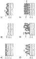
- FIG. 2 is an explanatory diagram for explaining the process of increasing the thickness of the Li metal negative electrode.
- the negative electrode plate is formed by forming an active material layer 62 made of Li metal on a base material foil 61 which is a plate-shaped metal foil made of a metal such as copper or an alloy of copper.
- a film 64 called an SEI film is formed on the surface of the precipitated Li layer 63 by a decomposition product of a component of the electrolytic solution or the like (FIG. 2A).
- Li of the precipitated Li layer 63 is released into the electrolytic solution, but not all of it is dissolved, a part of Li63a remains on the active material layer 62, and the surface of the active material layer 62 becomes non-uniform. (Fig. 2B).
- the coating film 64 containing the dead Li63b has a gap between the surface of the active material layer 62 and another coating film 64.
- a part of the coating film 64 containing the dead Li is discharged to the electrolytic solution in a state of containing the dead Li 63b.
- a part of the coating film 64 containing the dead Li remains on the surface of the active material layer 62 in a state where the root portion adheres to the active material layer 62 at the time of discharge.
- the porous film 64 is formed on the surface of the active material layer 62.
- Li ions of the electrolytic solution enter through the gap portion of the film 64 having a small resistance and precipitate on the surface of the active material layer 62.
- the Li metal is unevenly deposited on the active material layer 62, and dendrite 63c is generated. Inclusion of dendrite 63c and dead Li63b increases the thickness of the porous coating 64 deposits (FIG. 2F).
- the increase rate of the thickness of the energy storage element is 10% at the maximum, but in the case of the Li metal negative electrode, the increase in the thickness of the deposit of the porous coating 64 causes the dendrite 63c. Grow, which further accelerates the increase in thickness of the porous coating 64 deposits.
- the dendrite 63c grows rapidly, breaks through the separator, and a short circuit occurs. Since the thickness increases rapidly and a short circuit occurs, unlike a conventional lithium ion secondary battery using graphite as a negative electrode active material, it is not possible to detect an abnormality from current, voltage, and temperature information and predict a short circuit.
- FIG. 3 is an image diagram showing the relationship between time and the thickness of the power storage element. If it deviates from the first relationship between the amount of electricity and the rate of increase in thickness as shown in FIG. Very big.
- the state of the power storage element can be estimated and a sign of abnormality can be detected.
- the estimation device derives estimation information including a change in the shape and / or pressure of a power storage element having a negative electrode which deposits Li during charging and discharges the Li into an electrolytic solution during discharge and an exterior body.
- a first derivation unit is provided, and an estimation unit that estimates the state of the power storage element based on the derived estimation information.
- examples of the negative electrode include a metal negative electrode containing a metal such as Li metal or Na (sodium).
- the change in shape and / or pressure is the amount of displacement related to the change in shape such as the thickness of the power generation element, the amount of displacement of the exterior body accommodating the power generation element, and the change in the force (reaction force) at which the exterior body spreads outward.
- the power generation element is formed by laminating a positive electrode plate, a separator, and a negative electrode plate, or the positive electrode plate and the negative electrode plate are wound flat through a separator.
- the displacement amount may be the displacement amount in the thickness direction (direction intersecting the long side surface) of the power generation element or the exterior body, or may be the displacement amount of the laminated film exterior body, for example, the tapered portion where the terminal protrudes. ..
- Changes in the shape and / or pressure of the power storage element can be acquired by imaging with a thickness sensor, a pressure sensor, a camera, or the like.
- the thickness sensor include an X-ray CT (computed tomography) device, a laser displacement sensor, a strain sensor (strain gauge), and the like.
- the pressure sensor may measure the compression force (binding force) of a pair of end plates that sandwich the stacked storage elements in a state of pressing in the stack direction. When the internal pressure of the power storage element increases, the compression force between the end plates increases.
- the pressure sensor may measure the reaction force of each power storage element or the pressure applied to at least one surface of the power storage element. Regardless of whether the power storage element is completely restrained, free, or in between, the shape change can be acquired to detect a sign of abnormality in the power storage element.
- the exterior body may include a laminated film or may be made of a metal can.
- the laminated film is a film in which resin film layers are laminated and bonded (laminated) on both sides of the metal layer, and aluminum, nickel, or the like can be used for the metal layer.
- the change in the shape and / or pressure of the negative electrode can be estimated by deriving the estimation information including the change in the shape and / or pressure of the power storage element, and the state of the power storage element ( The degree of abnormality) can be estimated.
- a sign of abnormality can be detected accurately based on the state of the power storage element.
- the estimation information is a change in the shape and / or pressure of the power storage element due to deposits on the negative electrode containing a SEI coating containing dead Li that is not involved in the reaction and dendrites of Li. It may be the information of.
- the state of the power storage element can be accurately estimated from the information based on this deposit.
- the negative electrode may have an active material containing Li metal.
- the amount of change in shape is large, and the change may occur rapidly.
- the amount of change in the shape of the negative electrode can be grasped, and the state of the power storage element can be estimated accurately.
- the estimation unit when the estimation information is input, the estimation unit inputs the estimation information derived by the first derivation unit into a learning model that outputs information related to the state of the power storage element.
- the state of the power storage element may be estimated.
- the state of the power storage element can be easily and accurately estimated.
- the above-mentioned estimation device may include a determination unit for determining the presence or absence of a sign of abnormality based on the state of the power storage element estimated by the estimation unit.
- the estimation device derives estimation information including a change in the shape and / or pressure of a power storage element having a negative electrode which deposits Li during charging and discharges the Li into an electrolytic solution during discharge and an exterior body.
- the estimation information derived by the first derivation unit is input to the learning model that outputs the information related to the sign of the abnormality of the power storage element when the estimation information is input to the first derivation unit. It is provided with a determination unit for determining the presence or absence of a sign of abnormality in the element.
- the power storage element specified based on the state estimated by the estimation unit or the sign of the abnormality determined by the determination unit is provided with an energization control unit that stops energization at least during charging. May be good.
- the energization control unit may include a discharge control unit that discharges a power storage element that has stopped energization.
- the operation when it becomes difficult to operate only with the power storage element in use, the operation can be executed by returning the power storage element that is stopped energization and discharging it.
- the energization control unit includes a second derivation unit for deriving the resistance of a plurality of power storage elements whose energization is stopped, and the discharge control unit selects based on the resistance derived by the second derivation unit.
- the stored storage element may be discharged.
- the resistance of the power storage element is not only the amount of dendrite but also the total resistance of the positive electrode, the negative electrode, the electrolytic solution, the current collector, etc., and varies depending on the power storage element.
- the larger the resistance of the power storage elements the larger the amount of heat generated and the higher the temperature of the power storage elements. Dendrites formed when the temperature of the power storage element is high tend to be less likely to cause a short circuit.
- the estimation method derives estimation information including a change in the shape and / or pressure of a power storage element having a negative electrode, which precipitates Li during charging and discharges the Li into an electrolytic solution during discharging, and an exterior body. Then, the state of the power storage element is estimated based on the derived estimation information.
- the state of the power storage element can be accurately estimated based on the estimation information.
- the computer program according to the embodiment derives estimated information including a change in the shape and / or pressure of a power storage element having a negative electrode which deposits Li during charging and discharges the Li into an electrolytic solution during discharging and an exterior body. Then, the computer is made to execute the process of estimating the state of the power storage element based on the derived estimation information.
- the state of the power storage element can be accurately detected based on the estimated information.
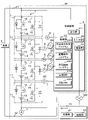
- FIG. 4 is a block diagram showing the configurations of the charge / discharge system 30 and the server 40 according to the first embodiment.
- the charging / discharging system 30 is provided in, for example, transportation equipment including automobiles and railroads, industrial equipment including aerospace / construction, and the like, and examples thereof include a battery module 1 having a large depth at one discharge.
- the charge / discharge system 30 includes a battery module 1, a control device 2, a voltage sensor 6, a current sensor 7, a temperature sensor 8, a thickness sensor 9, a pressure sensor 10, and a camera 20.
- the control device 2 controls the entire charge / discharge system 30.
- the control device 2 includes a control unit 21, a storage unit 22, an input unit 23, and a communication unit 24.
- the server 40 includes a control unit 41 and a communication unit 42.
- the control unit 21 of the control device 2 is connected to the control unit 41 via the communication unit 24, the network NW, and the communication unit 42.
- the load 3 is connected to the battery module 1 via the terminals 31 and 32. When charging, a charger is connected to the battery module 1.
- the control units 21 and 41 are composed of, for example, a CPU (Central Processing Unit), a ROM (Read Only Memory), a RAM (Random Access Memory), and the like, and control the operations of the control device 2 and the server 40, respectively.
- a CPU Central Processing Unit
- ROM Read Only Memory
- RAM Random Access Memory
- the storage unit 22 stores various programs and data.
- the storage unit 22 stores an abnormality degree estimation program 221 (hereinafter referred to as program 221), an energization control program 222 (hereinafter referred to as program 222), and a discharge control program 223 (hereinafter referred to as program 223).
- the programs 221 and 222, and the program 223 are provided and controlled in a state of being stored in computer-readable recording media 25, 26, 27 such as a CD-ROM, a DVD-ROM, and a USB (universal serial bus) memory. By installing it in the device 2, it is stored in the storage unit 22. Further, the programs 221 and 222 and the program 223 may be acquired from an external computer (not shown) connected to the communication network and stored in the storage unit 22.
- the history DB (database) 224 is also stored in the storage unit 22.
- FIG. 5 is an explanatory diagram showing an example of the record layout of the history DB 224.
- the history DB 224 has a current, a voltage, a temperature, a SOC (State of Charge), a pressure, a thickness, an image data, a displacement amount obtained by processing the image data, and an abnormality for each cell 12 and each estimation time point in charging. I remember the degree.
- FIG. 5 shows the ID No. The history of cell 12 of 1 is shown.
- the history DB 224 is No.
- the column, the current column, the voltage column, the temperature column, the SOC column, the pressure column, the thickness column, the image data column, the image column of the displacement amount column, and the abnormality degree sequence are stored.
- the history DB 224 may further store a time (date and time) column.
- the column is No. 1 of the estimation process of the degree of abnormality. I remember (number of times). Since the short circuit is caused by the growth of dendrites during charging, the estimation process may be performed at predetermined intervals during charging.
- the current train stores the history of the current acquired from the current sensor 7 at the time of estimation.
- the voltage train stores the voltage acquired from the voltage sensor 6 at the time of estimation.
- the temperature sequence stores the temperature acquired from the temperature sensor 8 at the time of estimation.
- the SOC column stores the SOC at the time of estimation. SOC is derived by the current integration method or the like.
- the pressure train stores the pressure acquired from the pressure sensor 10 at the time of estimation.
- the thickness column stores the thickness acquired from the thickness sensor 9 at the time of estimation.
- the image data string stores the image data acquired by the camera 20 at the time of estimation.
- the displacement amount sequence stores the displacement amount from the initial state obtained by processing the image data by the image processing program (not shown) stored in the storage unit 22.
- the anomaly degree sequence stores the anomaly degree derived based on the rule base described later.
- the degree of abnormality is represented by four stages of 0 to 3, and "0" is a normal state, there is no sign of abnormality, and the thickness of the cell 12 increases as the numerical value increases. When it becomes "3", it is necessary to take measures to prevent the occurrence of an abnormal state.
- the degree of anomaly is estimated based on threshold values such as pressure, thickness, and displacement. The threshold value is set to be smaller than the obtained pressure, thickness, displacement amount, etc.
- the degree of abnormality is estimated based on the pressure, thickness, and displacement amount actually measured and derived at the time of estimation.
- the degree of anomaly is not limited to four stages.
- a sign presence / absence column that stores the presence / absence of a sign may be stored, or in addition to the abnormality degree sequence, a sign presence / absence column may be stored.
- FIG. 6 is an explanatory diagram showing an example of a rule-based model for estimating the degree of anomaly.
- FIG. 6A for convenience, No. 1 to No. The four cases of 4 will be described.
- the case where the four-step abnormality degree is derived by using the pressure, the thickness, and the displacement amount will be described, but the case is not limited to this case. Any one of pressure, thickness, and displacement may be used, or current, voltage, temperature, SOC, time, or the like may be used. Further, a value obtained by calculating these quantities (for example, the time change rate of the thickness, etc.) may be used.
- the displacement amount may be, for example, the deformation amount of one cell 12 measured by the camera 20, or the deformation amount of the entire battery module 1 including the cell 12.
- the thickness may be, for example, the thickness of one cell 12 measured by the thickness sensor 9, or the thickness of the entire battery module 1 including the cell 12.
- FIG. 6B shows an example of a rule-based model using thickness, time change rate of thickness, pressure, and time change rate of pressure. No. shown in FIG. 6B.
- the thickness, the time change rate of the thickness, the pressure, and the time change rate of the pressure are all less than the threshold value, and the degree of abnormality is “0”.
- the degree of abnormality is “0”.
- any one of the thickness, the time change rate of the thickness, the pressure, and the time change rate of the pressure is equal to or more than the threshold value, the other is less than the threshold value, and the degree of abnormality is "1". be. No.
- any two of the thickness, the time change rate of thickness, the pressure, and the time change rate of pressure are above the threshold value, and the others are below the threshold value, and the degree of abnormality is "2". be. No. In the cases of 12 to 15, any one of the thickness, the time change rate of the thickness, the pressure, and the time change rate of the pressure is less than the threshold value, the other is more than the threshold value, and the degree of abnormality is "3". be. No. In the case of 16, the thickness, the time change rate of the thickness, the pressure, and the time change rate of the pressure are all equal to or more than the threshold value, and the degree of abnormality is “3”. In this way, the degree of abnormality can be determined according to the thickness, the time change rate of the thickness, the pressure, and the comparison between the time change rate of the pressure and the threshold value.
- the relationship DB 225 may store the first relationship between the time in the normal state and the cell thickness as shown in FIG. In this case, the state of the cell 12 is estimated based on whether or not the second relationship between the time and the change in the thickness of the cell 12 is deviated from the first relationship, and whether or not the thickness exceeds the threshold value of the sign. The presence or absence of a sign is determined based on the above.
- the communication units 24 and 42 have a function of communicating with other devices via the network NW, and can transmit and receive required information.
- either the control device 2 or the server 40 functions as the estimation device of the present invention.
- the entire system including the control device 2 and the server 40 may be the estimation device of the present invention, the control device 2 may function as the first derivation unit, and the server 40 may function as the estimation unit. If the server 40 does not function as an estimation device, the charge / discharge system 30 may not be connected to the server 40.
- the control device 2 may be a battery ECU (Electronic Control Unit).
- the voltage sensor 6 is connected in parallel to the battery module 1 and outputs a detection result according to the overall voltage of the battery module 1.
- the voltage sensor 6 is connected to the positive electrode terminal 12b and the negative electrode terminal 12c described later of each cell 12, measures the voltage V 1 between the positive electrode terminal 12b and the negative electrode terminal 12c of each cell 12, and V 1 of each cell 12.
- the voltage V which is the total value of, is detected.
- the current sensor 7 is connected in series with the battery module 1 and outputs a detection result according to the current of the battery module 1.
- the thickness sensor 9 includes an X-ray CT device, a laser displacement sensor, a strain sensor, and the like. The thickness sensor 9 measures the thickness of the cell 12 of the battery module 1 in the stack direction.
- the pressure sensor 10 measures the pressing force of a pair of end plates 17, which will be described later, that sandwich the battery module 1 in a state of pressing in the stack direction.
- the pressure sensor 10 may measure the force spreading outside the battery module 1 or the pressure applied to at least one surface of the battery module 1.
- the internal pressure of each cell 12 may be measured by the pressure sensor 10.
- the bulge of the cell 12 arranged at the outermost position on one side of the battery module 1 may be used.
- the swelling (distortion) of the end plate 17 may be measured.
- the gap between the cells 12 may be measured.
- the compression force of the end plate 17 of the cell 12 may be measured and the compression force may be used instead of the swelling amount.
- Examples of the method for measuring the compression force include a method of pushing the end plate 17 to measure the repulsive force, a method of removing the fixing bolt and measuring the repulsive force, and the like.
- the camera 20 takes an image of a portion of the exterior body 12f of each cell 12, which will be described later, in which terminals protrude from the power generation element 12a and are tapered.
- FIG. 4 shows a case where one set of battery modules 1 is provided, a plurality of sets of battery modules 1 may be connected in series.
- the battery module 1 includes a plurality of battery circuits 11.
- Each battery circuit 11 includes one cell 12 and is a circuit through which a current flows when the battery module 1 charges and discharges.
- the plurality of battery circuits 11 are connected in series. When the battery module 1 charges and discharges, a current flows through the plurality of battery circuits 11, and the plurality of cells 12 charge and discharge.
- the battery circuit 11 includes a first electric circuit 13, a cell 12 provided in the first electric circuit 13, and a first switch 14 provided in the first electric circuit 13 and connected in series to the cell 12.
- the cell 12 is connected to the adjacent battery circuit 11 via the first electric circuit 13 and the first switch 14.
- the first switch 14 is configured by using a FET (field effect transistor).
- the first switch 14 is provided in the first electric circuit 13 so that the forward direction of the body diode is the charging direction of the battery module 1.
- the first switch 14 makes the first electric circuit 13 conductive when it is on, and makes the first electric circuit 13 non-conducting in the discharge direction of the battery module 1 when it is off.
- the first switch 14 when the first switch 14 is on, the cell 12 is connected to another battery circuit 11 through the first electric circuit 13 and can be charged and discharged.
- the first switch 14 is off, no current flows through the cell 12 in the discharge direction, but current flows through the body diode of the first switch 14 in the charge direction.
- the battery circuit 11 further includes a second electric circuit 15 connected to another battery circuit 11 in parallel with the cell 12 and the first switch 14, and a second switch 16 provided in the second electric circuit 15.
- the second switch 16 is configured by using FET.
- the first switch 14 and the second switch 16 are connected in the battery circuit 11 so as to have opposite polarities to each other.
- the second switch 16 is provided in the second electric circuit 15 so that the forward direction of the body diode is the discharge direction of the battery module 1.
- the second switch 16 when the second switch 16 is turned on when the first switch 14 is turned off, the charging current does not flow to the cell 12, and the second electric circuit 15 becomes a bypass and bypasses the cell 12. In this state, charging current flows through other battery circuits.
- the second switch 16 makes the second electric circuit 15 conductive when it is on, and makes the second electric circuit 15 non-conducting in the charging direction of the battery module 1 when it is off.
- the cell 12 is connected to another battery circuit 11 through the first electric circuit 13.
- FIG. 7 is a cross-sectional view of the battery module 1
- FIG. 8 is a perspective view of the cell 12.
- the cell 12 includes a power generation element 12a, a positive electrode terminal 12b, a negative electrode terminal 12c, and an exterior body 12f composed of a laminated film 12d and 12e.
- the exterior body 12f is formed by superimposing two laminated films 12d and 12e and welding a peripheral portion thereof.
- the positive electrode terminal 12b and the negative electrode terminal 12c protruding from the power generation element 12a are drawn out to the outside through the welded portion of the exterior body 12f.
- the laminating films 12d and 12e are formed by laminating a PE welding layer, a PET layer, an aluminum layer, a PET layer, and a PE welding layer in this order from the inside to the outside where the power generation element 12a is arranged.
- the stacking configuration is not limited to this case.
- the plurality of cells 12 are sandwiched by a pair of end plates 17 and 17 in a state of being pressed in the stack direction.
- the power generation element 12a is formed by laminating a positive electrode plate, a separator, and a negative electrode plate, and is housed in the exterior body 12f.
- the negative electrode plate corresponds to the negative electrode in the present invention.
- the power generation element 12a may be obtained by winding a positive electrode plate and a negative electrode plate in a flat shape via a separator, or may be obtained by laminating a plurality of positive electrode plates and a negative electrode plate via a separator. There may be.
- the positive electrode plate has an active material layer formed on a positive electrode base material foil which is a plate-shaped (sheet-shaped) or long strip-shaped metal foil made of a metal such as aluminum, titanium, tantalum, or stainless steel or an alloy thereof. It is a thing.
- the negative electrode plate has an active material layer formed on a negative electrode base material foil, which is a plate-shaped (sheet-shaped) or long strip-shaped metal foil made of a metal such as copper, nickel, stainless steel, nickel-plated steel, or an alloy thereof. It was done.
- the separator is a microporous sheet made of synthetic resin.
- the positive electrode active material for example, a known positive electrode active material can be appropriately selected.
- the positive electrode active material for a lithium secondary battery a material capable of occluding and releasing Li ions is usually used.
- the positive electrode active material include a lithium transition metal composite oxide having an ⁇ -NaFeO type 2 crystal structure, a lithium transition metal oxide having a spinel type crystal structure, and the like.
- Fe is iron.
- the lithium transition metal composite oxide having an ⁇ -NaFeO type 2 crystal structure include Li [Li x Ni 1-x ] O 2 (0 ⁇ x ⁇ 0.5) and Li [Li x Ni ⁇ Co (1- ).
- Ni nickel
- Co cobalt
- Al aluminum
- examples of the lithium transition metal oxide having a spinel-type crystal structure include Li x Mn 2 O 4 and Li x Ni ⁇ Mn (2- ⁇ ) O 4 .
- the surface of these materials may be coated with other materials.
- one of these materials may be used alone, or two or more of them may be mixed and used.
- one of these compounds may be used alone, or two or more thereof may be mixed and used.
- the content of the positive electrode active material in the positive electrode active material layer is not particularly limited, but the lower limit thereof is preferably 50% by mass, more preferably 80% by mass, still more preferably 90% by mass.
- the upper limit of the content is preferably 99% by mass, more preferably 98% by mass.
- the positive electrode mixture that forms the active material layer of the positive electrode plate contains optional components such as a conductive agent, a binder, a thickener, and a filler, if necessary.
- a conductive agent include carbonaceous materials such as carbon black, metals, conductive ceramics and the like.
- the binder include fluororesins (polytetrafluoroethylene (PTFE), polyvinylidene fluoride (PVDF), etc.), thermoplastic resins such as polyethylene, polypropylene, and polyimide.
- the thickener include polysaccharide polymers such as carboxymethyl cellulose (CMC) and methyl cellulose.
- the filler include polyolefins such as polypropylene and polyethylene.
- the negative electrode active material used for the negative electrode active material layer preferably contains Li metal. Since the negative electrode active material contains Li metal, it has excess Li ions, and Li ions can be transferred from the negative electrode plate to the positive electrode plate to develop the required discharge capacity.
- Li metal includes Li alloy as well as Li alone. Examples of the Li alloy include a LiAl alloy and the like.
- the negative electrode plate containing the Li metal can be manufactured by cutting the Li metal into a predetermined shape or molding the Li metal into a predetermined shape. In this case, the negative electrode base material made of stainless steel may be connected only to the end portion of the Li metal plate.
- the negative electrode active material layer may contain elements such as Na, K (potassium), Ca (calcium), Fe, Mg (magnesium), Si and N (nitrogen).
- the negative electrode active material may contain Li metal and Si or SiO.
- the lower limit of the Li metal content in the negative electrode active material is preferably 80% by mass, more preferably 90% by mass, and even more preferably 95% by mass.
- the upper limit of the content may be 100% by mass.
- the electrolytic solution contains a non-aqueous solvent and a sulfur-based cyclic compound, a fluorinated cyclic carbonate, a chain carbonate, and an electrolyte salt dissolved in the non-aqueous solvent.
- a sulfur-based cyclic compound include compounds having a sultone structure or a cyclic sulfate structure.
- the fluorinated cyclic carbonate include fluoroethylene carbonate and the like.
- Examples of the chain carbonate include ethyl methyl carbonate and dimethyl carbonate.
- the negative electrode active material of the cell 12 may contain Li metal, and the positive electrode active material may be a lithium excess type. According to such a cell 12, a high discharge capacity can be exhibited.
- NCM Ni + Co + Mn-based mixed positive electrode active material
- a plurality of cells 12 are connected in series by electrically connecting the positive electrode terminals 12b and the negative electrode terminals 12c of the adjacent cells 12 of the battery module 1 by a bus bar (not shown).
- the positive electrode terminals 12b and the negative electrode terminals 12c of the cells 12 at both ends of the battery module 1 are provided with positive electrode leads and negative electrode leads (not shown) for extracting electric power.
- the exterior body 12f of the cell 12 may be made of a metal can.
- the positive electrode active material a lithium transition metal composite oxide having an ⁇ -NaFeO type 2 crystal structure and represented by Li 1 + ⁇ Me 1- ⁇ O 2 (Me is a transition metal) is used.
- a positive electrode paste containing a mass ratio of 0 is prepared.
- a positive electrode plate is coated with a positive electrode paste on both sides of an aluminum foil having a thickness of 15 ⁇ m as a positive electrode base material, dried, pressed, and cut, and a positive electrode active material layer is arranged in a rectangular shape having a width of 30 mm and a length of 40 mm. To make.
- the thickness of the positive electrode active material layer is about 110 ⁇ m on one side, and the positive electrode mixture is contained at 26 mg / cm 2 per unit area.
- the positive electrode plate is dried under reduced pressure at 120 ° C. for 14 hours or more before use.
- a metallic lithium foil (average thickness 100 ⁇ m: pure metallic lithium of 100% by mass of metallic lithium) was laminated and pressed as a negative electrode active material layer on both sides of an 8 ⁇ m copper foil as a negative electrode base material. As a result, a negative electrode plate in which negative electrode active material layers are laminated on both sides of the negative electrode base material is obtained.
- the negative electrode plate has a rectangular shape with a width of 30 mm and a length of 42 mm.
- FEC fluoroethylene carbonate
- DMC dimethyl carbonate
- a laminated type power generation element 12a is produced by alternately laminating a plurality of the positive electrode plates and the plurality of the negative electrode plates one by one and via a microporous film made of polyolefin which is a separator.
- the two laminated films 12d and 12e cover the power generation element 12a so that the open ends of the positive electrode terminal 12b and the negative electrode terminal 12c, which are previously connected to the positive electrode plate and the negative electrode plate, respectively, are exposed to the outside, and form a liquid injection hole. After injecting the electrolytic solution, the injection hole is hermetically sealed.
- the cell 12 is produced as described above.
- the configuration of the cell 12 is not limited to the above case. Lithium may be attached to the negative electrode plate.
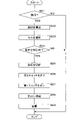
- FIG. 9 is a flowchart showing a procedure for estimating the degree of abnormality of the cell 12 by the control unit 21.
- the control unit 21 derives the history information (S1).
- the control unit 21 stores the current acquired from the current sensor 7 at the time of estimation in the history DB 224.
- the control unit 21 stores the voltage acquired from the voltage sensor 6 at the time of estimation in the history DB 224.
- the control unit 21 stores the temperature acquired from the temperature sensor 8 at the time of estimation in the history DB 224.
- the control unit 21 stores the SOC derived at the time of estimation in the history DB 224.
- the control unit 21 stores the pressure acquired from the pressure sensor 10 at the time of estimation in the history DB 224.
- the control unit 21 stores the thickness acquired from the thickness sensor 9 at the time of estimation in the history DB 224.
- the control unit 21 stores the image data acquired by the camera 20 at the time of estimation in the history DB 224.
- the control unit 21 stores in the history DB 224 the amount of displacement from the initial state obtained by processing the image data by the image processing program stored in the storage unit 22.
- the control unit 21 reads out the estimation information required for estimating the degree of abnormality from the history DB 224 (S2).
- the control unit 21 reads the relation DB 225 (S3).
- the control unit 21 estimates the degree of abnormality (S4) and determines whether or not there is a sign (S5).
- the control unit 21 estimates the degree of abnormality based on whether or not the pressure, thickness, and displacement amount read from the history DB 224 are each less than the threshold value.
- the degree of abnormality is "3"
- the control unit 21 determines that there is a sign.
- the relationship DB225 stores the first relationship between the time in the normal state and the thickness of the cell, the cell is based on whether or not the second relationship between the time and the change in thickness deviates from the first relationship.
- the state of 12 is estimated (S4), and the presence or absence of a sign is determined based on whether or not the thickness exceeds the threshold value of the sign (S5).
- the control unit 21 stores the degree of abnormality or the presence / absence of a sign in the history DB 224.
- the control unit 21 determines that there is a sign (S5: YES)
- the control unit 21 notifies that there is a sign (S6).
- the control unit 21 transmits information to the effect that there is a sign of abnormality to the server 40 or to the user's terminal device through the communication unit 24.
- there is no sign (S5: NO)
- the control unit 21 ends the process.
- the control unit 21 may specify the cell 12 having a sign after estimating the presence or absence of a sign of abnormality in the battery module 1 as a whole.
- the estimation information including the change in the shape and / or pressure of the cell 12 by deriving the estimation information including the change in the shape and / or pressure of the cell 12, the change in the shape and / or pressure of the negative electrode is acquired, and the change in the shape and / or pressure of the negative electrode is acquired with high accuracy based on the estimation information.
- the state of the cell 12 can be estimated, and a sign of an abnormality such as a short circuit can be detected with high accuracy.
- FIG. 10 is a flowchart showing a procedure of energization control processing of the cell 12 by the control unit 21.
- the control unit 21 determines whether or not there is a sign of abnormality in the target cell 12 (S11).
- the control unit 21 determines whether or not the degree of abnormality is “3”. When there is no sign (S11: NO), the control unit 21 ends the process.
- the control unit 21 determines whether or not the SOC at the time of estimation of the cell 12 having the sign is equal to or higher than the threshold value a (S12). When the SOC is not equal to or higher than the threshold value a (S12: NO), the control unit 21 ends the process. As will be described later, the cell 12 that has stopped energization during charging may be restored and discharged, and the SOC must be equal to or higher than the threshold value a when stopped.
- the control unit 21 When the SOC is equal to or higher than the threshold value a (S12: YES), the control unit 21 is specified as a cell 12 for stopping energization, and turns off the corresponding first switch 14 of the cell 12 (S13). The control unit 21 turns on the second switch 16 (S14) and ends the process.
- the second electric circuit 15 is in a conductive state, and the cell 12 having a sign is not connected to another battery circuit 11, and cannot be charged.
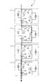
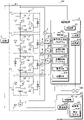
- FIG. 11 is a schematic circuit diagram showing a battery module 1 when charging is performed by stopping the energization of the second cell 12.
- the current flowing during charging is indicated by a solid arrow.
- the cell 12 which is the second from the top in FIG. 11, has a sign of abnormality.
- the first switch 14 is turned off, and the cell 12 is not connected to the other battery circuits 11.
- the second switch 16 is turned on, and the second electric path 15 is in a conductive state.
- the first switch 14 is on and the cell 12 is connected to the other battery circuit 11 via the first electric circuit 13.
- the second switch 16 is off, and the second electric path 15 is in a non-conducting state.
- a current flows through the cell 12 and the first electric circuit 13, and the cell 12 charges.
- the battery circuit 11 including the cell 12 having a sign no current flows through the cell 12 and the first electric circuit 13, and current flows through the second electric circuit 15. That is, no current flows through the cell 12 having a sign, and the second electric circuit 15 becomes a bypass and current flows through the second electric circuit 15.
- a current flows through the battery module 1 as a whole, and the normal cell 12 is charged. Since the cell 12 with a sign cannot be charged, it is prevented that the dendrite grows further and a short circuit occurs.
- FIG. 12 is a flowchart showing a procedure for processing the discharge control of the cell 12 by the control unit 21.
- the control unit 21 determines whether or not to return (S21).
- the control unit 21 determines whether or not it is difficult to operate only by the cell 12 in use. If the control unit 21 does not return (S21: NO), the control unit 21 ends the process.
- the control unit 21 When returning (S21: YES), the control unit 21 reads the history DB 224 and derives the resistance of the cell 12 in which the energization is stopped (S22). The control unit 21 reads out the initial current and voltage of the number of times of charging of the target cell 12 stored in the history DB 224, and derives the resistance.
- the control unit 21 selects the cell 12 to be discharged (S23).
- the control unit 21 selects the cell 12 having the larger resistance from the cells 12 from which the resistance is derived. As described above, when the resistance of the cell 12 is large, the amount of heat generated is large and a short circuit is unlikely to occur.
- the control unit 21 may select the cell 12 having a high SOC when the energization is stopped. If the SOC is high, it can be sufficiently discharged.
- the control unit 21 determines whether or not the load can be cut off (S24). If the control unit 21 is not disconnectable (S24: NO), the control unit 21 ends the process. When the control unit 21 can be disconnected (S24: YES), the control unit 21 disconnects the load (S25). The control unit 21 turns off the corresponding second switch 16 of the cell 12 (S26). The control unit 21 turns on the first switch 14 (S27). The second electric circuit 15 is in a non-conducting state, the first electric circuit 13 is in a conductive state, and the cell 12 is in a state of being connected to another battery circuit 11, so that discharge is possible.
- the control unit 21 connects the load to the battery module 1 (S28).
- the control unit 21 starts discharging (S29) and ends the process.
- the operation when it becomes difficult to operate only with the cell 12 in use, the operation can be executed by returning the cell 12 whose energization is stopped and discharging the cell 12.
- FIG. 13 is a perspective view of the appearance of the HAPS machine body 50
- FIG. 14 is a block diagram showing the configuration of the HAPS machine body 50.
- the same parts as those in FIG. 4 are designated by the same reference numerals, and detailed description thereof will be omitted.
- the solar panel 54 is omitted.
- the HAPS airframe 50 includes a wing portion 51, a plurality of propellers 52, a plurality of leg portions 53, a plurality of solar panels 54, a battery module 1, a control device 2, a motor 4, a wireless relay station 5, and the like. It is equipped with wheels 55.
- the propeller 52 is connected to the motor 4.
- the configuration of the HAPS aircraft 50 is not limited to this example.
- the battery module 1, the control device 2, and the wireless relay station 5 are housed in the leg portion 53. Alternatively, they may be provided on the wing 51.
- the HAPS aircraft 50 equipped with the wireless relay station 5 can be connected to a large number of terminal devices in a wide range at the same time, and by coordinating between the HAPS aircraft 50 and artificial satellites and ground stations, a high-speed communication infrastructure can be created. Can be built. A stable communication environment can be maintained even in the event of a disaster.
- the solar panel 54 is formed by arranging and connecting a plurality of modules in which a plurality of silicon-based solar cells are arranged, for example.
- the battery module 1 is formed by connecting, for example, a plurality of cells 12 in series and / or in parallel. A plurality of battery modules 1 may be connected in series to form a bank, or banks may be connected in parallel.
- the cell 12 and the battery module 1 have the same configuration as the cell 12 and the battery module 1 according to the first embodiment.
- the control device 2 has the same configuration as the control device 2 of the first embodiment, and further has a motor drive unit 28.
- the storage unit 22 stores an abnormality degree estimation program 221, an energization control program 222, a discharge control program 223, a history DB 224, and a related DB 225.
- FIG. 15 is an explanatory diagram showing an example of the record layout of the history DB 224.
- the history DB 224 of the second embodiment stores a solar panel power generation amount column and an energy consumption column in addition to the column of the history DB 224 of the first embodiment.
- the solar panel power generation amount column stores the power generation amount of the solar panel 54.
- the energy consumption column stores the amount of energy consumed by the entire HAPS machine 50.
- the input unit 23 receives the detection results of the current and voltage of the solar panel 54 and the battery module 1.
- the communication unit 24 has a function of communicating with other devices such as the wireless relay station 5, and transmits / receives required information.
- the motor drive unit 28 controls the rotational drive of each motor 4 of each propeller 52.
- FIG. 14 shows a state in which the battery module 1 is connected to the load 3.
- the wireless relay station 5 includes a communication unit 56.
- the communication unit 56 has an antenna, a transmission / reception duplexer, an amplifier, and the like, and transmits / receives radio signals to / from a relay station on the ground or at sea.
- the wireless relay station 5 is connected to the network NW of the mobile communication network via the relay station.
- a server 40 and a terminal device 60 are connected to the network NW.
- the motor 4 rotationally drives the propeller 52. Alternatively, the motor 4 may drive a flying object propulsion device or a flying object raising device other than the form shown in FIG.
- the HAPS aircraft 50 configured as described above is lifted by lift while turning in a predetermined horizontal region after being separated from the ground diagonally upward, and ascends to the airspace A.
- the airspace A for example, an airspace within the stratosphere at an altitude of 11 km to 50 km can be mentioned. Above all, an airspace with an altitude of 20 km is preferable.
- the HAPS aircraft 50 After ascending to the airspace A, the HAPS aircraft 50 horizontally moves to the horizontal position B and stays at the position B.
- the battery module 1 supplies electric power.
- the battery module 1 supplies electric power for driving the motor 4 to fly, and is required even when the HAPS aircraft 50 glides in the airspace A, the control unit 21, the input unit 23, the communication unit 24, Power is supplied to the wireless relay station 5 and the like. Since power is supplied by the battery module 1 until power is generated by the solar panel 54, the depth of discharge at night becomes large. For example, the battery module 1 charges and discharges in the range of SOC 10% to 100%.
- the degree of abnormality of the cell 12 is estimated using the rule base stored in the relation DB 225 based on the pressure, the thickness, and the displacement amount of the cell 12.
- the degree of anomaly may be estimated based on any of pressure, thickness, and displacement, and in addition to pressure, thickness, and displacement, at least one of current, voltage, temperature, solar panel power generation, and energy consumption. The degree of anomaly may be estimated based on.
- the first switch 14 of the cell 12 When it is determined that there is a sign of abnormality based on the degree of abnormality of the cell 12, the first switch 14 of the cell 12 is turned off, the second switch 16 is turned on, and the energization during charging is stopped. This prevents a short circuit in the cell 12.
- the HAPS machine 50 is required to simultaneously connect to a large number of terminal devices in a wide range for a predetermined period such as half a year to construct a high-speed communication infrastructure. According to this embodiment, the life can be extended, stable discharge can be performed at night for a longer period of time, stable flight operation can be performed, and a stable communication environment can be maintained. Become.
- the control unit 21 determines that it is difficult to continue the flight with only the cell 12 in use, the control unit 21 selects the cell 12 having a high resistance and a high SOC from the cells 12 that have stopped energizing during charging. , The second switch 16 of the cell 12 is turned off, and the first switch 14 is turned on to restore the energization at the time of discharging. As a result, the HAPS aircraft 50 can be landed while avoiding a crash.
- FIG. 16 is a block diagram showing the configurations of the charge / discharge system 30 and the server 40 according to the third embodiment.
- the server 40 of the third embodiment includes a storage unit 43.
- the storage unit 43 includes a storage device such as a hard disk drive.
- the storage unit 43 stores various computer programs executed by the control unit 41, various data used by the computer programs, data acquired from the outside, and the like.
- An example of a computer program stored in the storage unit 43 is a model generation program for generating a learning model 430.
- the storage unit 43 may store training data including the image data of the cell 12 and the label data indicating the degree of abnormality. These data may be acquired from the control device 2 via the communication unit 42.
- the history DB 224 of the control device 2 of the third embodiment does not store the displacement amount based on the image data. Since the image data is input to the learning model 430 to estimate the degree of abnormality, it is not necessary to perform image processing to derive the displacement amount.
- FIG. 17 is a schematic diagram showing the configuration of the learning model 430 in the third embodiment.
- the learning model 430 in the third embodiment is a learning model based on CNN (Convolutional Neural Networks), R-CNN (Region-based CNN), etc., and includes an input layer 431, an intermediate layer 432, and an output layer 433.
- the learning model 430 is trained to output the degree of abnormality with respect to the input of the image data in the cell 12.
- the learning model 430 is generated, for example, by the server 40 and stored in the storage unit 22 of the control device 2.
- Image data is input to the input layer 431 of the learning model 430.
- the intermediate layer 432 is composed of, for example, a convolutional layer 432a, a pooling layer 432b, and a fully connected layer 432c.
- a plurality of convolution layers 432a and pooling layers 432b may be provided alternately.
- the convolution layer 432a and the pooling layer 432b extract the features of the image data input through the input layer 431 by the calculation using the nodes of each layer.
- the fully connected layer 432c combines the data whose feature portions are extracted by the convolution layer 432a and the pooling layer 432b into one node, and outputs the feature variable converted by the activation function.
- the feature variable is output to the output layer 433 through the fully connected layer 432c.
- the output layer 433 includes one or more nodes.
- the output layer 433 converts it into a probability using a softmax function based on the feature variable input from the fully connected layer 432c of the intermediate layer 432, and outputs, for example, the probability indicating each abnormality degree from 0 to 3 from each node. do.
- the output layer 433 is composed of four nodes from the first node to the fourth node, the probability that the degree of abnormality is 0 from the first node, the probability that the degree of abnormality is 1 from the second node, and the probability that the degree of abnormality is 1 from the third node.
- the probability that the degree of abnormality is 2, and the probability that the degree of abnormality is 3 may be output from the fourth node.
- the output layer 433 is For example, the degree of abnormality is 0 ... 0.04 Degree of abnormality 1 ... 0.90 Degree of abnormality 2 ... 0.05 Degree of abnormality 3 ... 0.01 Output as.
- the number of nodes constituting the output layer 433 and the calculation result assigned to each node are not limited to the above example, and can be appropriately designed.
- the output layer 433 may include one node and output a probability with a sign.
- the training data includes the image data of the cell 12 and the label data indicating the presence or absence of a sign.
- the control unit 21 of the control device 2 can estimate the degree of abnormality by referring to the calculation result obtained from the learning model 430 and selecting, for example, the node having the highest probability.
- the internal parameters (weights and biases between nodes) that determine the configuration of the learning model 430 are learned, for example, by using an appropriate learning algorithm in the server 40.
- FIG. 18 is a flowchart showing the procedure of the generation process of the learning model 430 by the control unit 41.
- the control unit 41 collects image data of the tapered portion of the cell 12 and label data indicating the degree of abnormality of the cell 12, and stores the collected data as training data in the storage unit 43.
- S31 the accuracy of estimating the degree of abnormality can be improved. If the learning progresses, the estimation result by the learning model 430 and the image data used for the estimation process may be acquired, and the acquired data may be used as training data.
- the control unit 41 uses the training data to generate a learning model 430 that outputs the probability of the degree of abnormality when the image data is input (S32). Specifically, the control unit 41 inputs the training data to the input layer 431, performs arithmetic processing on the intermediate layer 432, and acquires the probability of the degree of abnormality from the output layer 433. The control unit 41 compares the estimation result of each abnormality degree output from the output layer 433 with the abnormality degree information labeled with respect to the image data in the training data, that is, the correct answer value, and the output value from the output layer 433. Is optimized for the parameters used in the arithmetic processing in the intermediate layer 432 so that is close to the correct answer value.
- the parameters are, for example, a weight (coupling coefficient), a coefficient of an activation function, and the like.
- the method of optimizing the parameters is not particularly limited, but for example, the control unit 41 optimizes various parameters by using the error back propagation method.
- the control unit 41 performs the above processing on the image data of each training data to generate the learning model 430.
- the control unit 41 stores the generated learning model 430 in the storage unit 43, and ends a series of processes. Not only the image data but also the pressure and the thickness may be input to the input layer 431 for learning. Further, current, voltage, temperature, SOC and the like may be input.
- the charging / discharging system is provided in the HAPS machine 50, the amount of power generated by the solar panel and the energy consumption may be input.
- the control device 2 downloads the learning model 430 generated in the server 40.
- the control device 2 can estimate the degree of abnormality in the cell 12 by inputting the image data acquired at the time of estimation into the learning model 430.
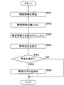
- FIG. 19 is a flowchart showing a procedure for estimating the degree of abnormality of the cell 12 by the control unit 21.
- the control unit 21 derives the history information (S41).
- the control unit 21 reads out the estimated information from the history DB 224 (S42).
- the image data is read out as the estimation information.
- the control unit 21 inputs image data as estimation information into the learning model 430 (S43).
- the control unit 21 estimates the degree of abnormality based on the probability of the degree of abnormality output by the learning model 430 (S44).
- the control unit 21 acquires the degree of abnormality having the highest probability and estimates the sign.
- the control unit 21 determines whether or not there is a sign (S45). When the degree of abnormality is "3", the control unit 21 determines that there is a sign. When the control unit 21 determines that there is a sign (S45: YES), the control unit 21 notifies that there is a sign (S46).
- the control unit 21 transmits information to the effect that there is a sign of abnormality to the server 40 or to the user's terminal device through the communication unit 24.
- the control unit 21 determines that there is a sign when the probability with a sign output by the learning model 430 is, for example, 50% or more. When there is no sign (S45: NO), the control unit 21 ends the process.
- the state of the cell 12 can be easily and accurately estimated, and the sign of an abnormality in the cell 12 can be determined.
- an example of supervised learning using CNN is shown, but it is also possible to estimate the state of the cell 12 by using unsupervised learning, regression, or the like.
- the power storage element is not limited to the lithium secondary battery.
- the power storage element may be another secondary battery or a capacitor.
Landscapes
- Chemical & Material Sciences (AREA)
- Engineering & Computer Science (AREA)
- Manufacturing & Machinery (AREA)
- Chemical Kinetics & Catalysis (AREA)
- Electrochemistry (AREA)
- General Chemical & Material Sciences (AREA)
- Secondary Cells (AREA)
- Physics & Mathematics (AREA)
- General Physics & Mathematics (AREA)
- Inorganic Chemistry (AREA)
- Power Engineering (AREA)
- Condensed Matter Physics & Semiconductors (AREA)
- Remote Monitoring And Control Of Power-Distribution Networks (AREA)
- Charge And Discharge Circuits For Batteries Or The Like (AREA)
Abstract
推定装置(2)は、充電時にLiが析出し、放電時に前記Liを電解液中に放出する負極と、外装体とを有する蓄電素子(12)の形状及び/又は圧力の変化を含む推定情報を導出する第1導出部(21)と、導出した前記推定情報に基づいて、蓄電素子(12)の状態を推定する推定部(21)とを備える。
Description
本発明は、蓄電素子の状態を推定する推定装置、推定方法、及びコンピュータプログラムに関する。
電気エネルギーを蓄積し、必要な時に動力源としてエネルギーを供給できる蓄電素子が利用されている。蓄電素子は、携帯機器、電源装置、自動車や鉄道を含む輸送機器、航空・宇宙・建設用を含む産業用機器等に適用されている。
蓄電素子(以下、電池ともいう)の高容量化を実現するために、負極の高容量化が求められている。特許文献1のリチウム二次電池においては、負極活物質としてLi(リチウム)金属を含むことが開示されている。負極にLi金属を用いることによって、負極の放電容量はグラファイトを用いた場合の372mAh/gから3860mAh/gへ著しく向上する。Li金属を含む負極を用いた場合、負極の電位は常に0Vvs.Li/Li+であり、グラファイトを用いた場合より電位が低くなり、電池電圧を大きくすることができる。それに伴い正極もより低い電位の容量を発現することができ、電池のエネルギー密度が飛躍的に向上する。
しかしながら、電池は、充放電が繰り返されることで徐々に劣化する。従って、電池の使用可否、使用方法を決定する上で、電池のSOH(State of Health:容量維持率等)及び異常の有無を容易に、かつ正確に推定することは重要な課題である。
一方、近年、環境問題を背景に、航空機産業における電動化が急速に進行している。航空機用途の電池には、高いエネルギー密度のみならず、高い安全性及び信頼性が求められる。新たな通信システムとしてHAPS(High-altitude platform station:成層圏プラットフォーム)が提案されている。このような用途に使用する飛行体は、一度離陸すると、長期間地上に戻らない。そのため、万一電池に異常が生じた場合、適切に対処する必要がある。しかし、異常が発生してから対処することは困難である。また、負極活物質としてLi金属を含む電池は、高いエネルギー密度を有するため、前記飛行体向け電池の一つとして有望である。
負極活物質としてLi金属を含む電池は、上述したように高いエネルギー密度を有するが、充電時にLiがデンドライト状に析出し、セパレータを突き破って短絡が生じることがある。即ち、安全性及び寿命特性に問題がある「電池の異常状態」となることがある。負極活物質としてグラファイトを用いた従来のリチウムイオン二次電池と異なり、電流、電圧、及び温度に基づいて電池の異常を判断することは困難である。遠隔操作で電池の充放電を制御する等の対策のために、早い段階で異常を検知する必要がある。
本発明の目的は、蓄電素子の状態を推定する推定装置、推定方法、及びコンピュータプログラムを提供することにある。
本発明の目的は、蓄電素子の状態を推定する推定装置、推定方法、及びコンピュータプログラムを提供することにある。
本発明の一態様に係る推定装置は、充電時にLiが析出し、放電時に前記Liを電解液中に放出する負極と、外装体とを有する蓄電素子の形状及び/又は圧力の変化を含む推定情報を導出する第1導出部と、導出した前記推定情報に基づいて、蓄電素子の状態を推定する推定部とを備える。
本発明の一態様に係る推定方法は、充電時にLiが析出し、放電時に前記Liを電解液中に放出する負極と、外装体とを有する蓄電素子の形状及び/又は圧力の変化を含む推定情報を導出し、導出した前記推定情報に基づいて、前記蓄電素子の状態を推定する。
本発明の一態様に係るコンピュータプログラムは、充電時にLiが析出し、放電時に前記Liを電解液中に放出する負極と、外装体とを有する蓄電素子の形状及び/又は圧力の変化を含む推定情報を導出し、導出した前記推定情報に基づいて、前記蓄電素子の状態を推定する処理をコンピュータに実行させる。
上記の態様によれば、蓄電素子の状態を推定することができる。
(実施形態の概要)
本明細書において、「蓄電素子」とは、少なくとも電池、電池セル(或いはセル)であっても良いし、電池モジュールや電池パックでも良い。また、蓄電素子は、電気二重層コンデンサやキャパシタ等であってもよい。
グラファイト等を活物質として含む炭素負極の場合、活物質は層状をなし、充電時のLi(リチウム)の吸蔵による活物質の膨張、放電時のLiの放出による活物質の収縮は理論通りに行われる。サイクル数の増加に伴い、活物質の膨張及び収縮による新たな界面が生じ、この界面にSEI(Solid Electrolyte Interphase)被膜が生じて負極の厚みが増加し、蓄電素子(セル)の厚みが増加するが、寿命末期の厚み増加率は最大で10%程度である。
本明細書において、「蓄電素子」とは、少なくとも電池、電池セル(或いはセル)であっても良いし、電池モジュールや電池パックでも良い。また、蓄電素子は、電気二重層コンデンサやキャパシタ等であってもよい。
グラファイト等を活物質として含む炭素負極の場合、活物質は層状をなし、充電時のLi(リチウム)の吸蔵による活物質の膨張、放電時のLiの放出による活物質の収縮は理論通りに行われる。サイクル数の増加に伴い、活物質の膨張及び収縮による新たな界面が生じ、この界面にSEI(Solid Electrolyte Interphase)被膜が生じて負極の厚みが増加し、蓄電素子(セル)の厚みが増加するが、寿命末期の厚み増加率は最大で10%程度である。
図1は、蓄電素子の累積の通電電気量と厚み増加率との関係を示すグラフである。図1中、aは活物質としてLi金属を含む負極を有する蓄電素子(正負極の単位面積あたりの容量:6mAh/cm2 )、bはグラファイト50%、Si(ケイ素)50%の活物質を含む負極を有する蓄電素子(正負極の単位面積あたりの容量:4.7mAh/cm2 )、cはグラファイト20%、SiO80%の活物質を含む負極を有する蓄電素子(正負極の単位面積あたりの容量:7.5mAh/cm2 )、dはグラファイト40%、SiO60%の活物質を含む負極を有する蓄電素子(正負極の単位面積あたりの容量:7.4mAh/cm2 )である。ここで、Oは酸素である。
図1中、横軸は累積の電気量(mAh)、縦軸は厚み増加率(%)である。
図1より、aのLi金属負極を有する蓄電素子の経時的な厚み増加率が最も大きいことが分かる。蓄電素子の厚みは負極の厚みの増加に起因する。
図1中、横軸は累積の電気量(mAh)、縦軸は厚み増加率(%)である。
図1より、aのLi金属負極を有する蓄電素子の経時的な厚み増加率が最も大きいことが分かる。蓄電素子の厚みは負極の厚みの増加に起因する。
図2は、Li金属負極における厚み増加のプロセスを説明するための説明図である。
負極板は、銅等の金属又は銅の合金等からなる板状の金属箔である基材箔61上にLi金属からなる活物質層62が形成されたものである。
負極板は、銅等の金属又は銅の合金等からなる板状の金属箔である基材箔61上にLi金属からなる活物質層62が形成されたものである。
充電時に、活物質層62上に、Liが析出して析出Li層63が形成される。析出Li層63の表面にSEI被膜と呼ばれる、電解液の成分の分解物等による被膜64が形成される(図2A)。
放電時に、析出Li層63のLiは電解液中に放出されるが、全部は溶解せず、一部のLi63aが活物質層62上に残存し、活物質層62の表面は不均一になる(図2B)。
放電時に、析出Li層63のLiは電解液中に放出されるが、全部は溶解せず、一部のLi63aが活物質層62上に残存し、活物質層62の表面は不均一になる(図2B)。
充電時にLiが活物質層62上に析出する場合、不均一な活物質層62の表面に形成されるので、析出Li層63は凹凸がある状態で形成される。この凹凸がある析出Li層63上に被膜64が形成される(図2C)。
充放電を繰り返すと、凹凸の度合が大きくなり、析出Li層63及び被膜64が形成される(図2D)。
充放電を繰り返すと、凹凸の度合が大きくなり、析出Li層63及び被膜64が形成される(図2D)。
Liが被膜64に包囲され、このLiは電池反応に関与しないデッドLi63bとなる(図2E)。デッドLi63bを包含する被膜64は、図2Eに示すように、活物質層62の表面、及び他の被膜64との間に間隙を有する。放電時に、デッドLiを包含した一部の被膜64は、デッドLi63bを包含した状態で電解液に放出される。デッドLiを包含した一部の被膜64は、放電時に、根元部分が活物質層62に付着した状態で、活物質層62の表面に残存する。ポーラスな被膜64が活物質層62の表面に形成されていることになる。
充電時に、電解液のLiイオンは、抵抗が小さい被膜64の間隙部分から入り込み、活物質層62の表面に析出する。Li金属は活物質層62上に不均一に析出し、デンドライト63cが生じる。
デンドライト63cと、デッドLi63bを包含し、ポーラスな被膜64の堆積物の厚みが増大する(図2F)。
デンドライト63cと、デッドLi63bを包含し、ポーラスな被膜64の堆積物の厚みが増大する(図2F)。
上述したように、炭素負極の蓄電素子の場合、蓄電素子の厚みの増加率は最大で10%であるが、Li金属負極の場合、ポーラスな被膜64の堆積物の厚みの増大により、デンドライト63cが成長し、それによって、さらにポーラスな被膜64の堆積物の厚みの増大が加速される。このように、急激な負極の厚みの増加に伴って、デンドライト63cが急激に成長し、セパレータを突き破って短絡が生じることになる。急激に厚みが増加して短絡するので、負極活物質としてグラファイトを用いた従来のリチウムイオン二次電池と異なり、電流、電圧、及び温度情報から異常を検出して短絡を予測することはできない。
本発明者等は蓄電素子の形状変化、即ち厚みの変化をモニタリングすることにより、蓄電素子の状態を推定し、異常、即ち短絡の予兆を検出(判定)することができることを見出した。
図3は、時間と蓄電素子の厚みとの関係を示すイメージ図である。
図1のa等に示す、電気量と厚み増加率との第1関係から逸脱し、即ち時間に対する厚みの増加率が大きい場合、異常状態であり、Liのデンドライトの成長により短絡する可能性が非常に大きい。蓄電素子の厚みをモニタリングすることで、蓄電素子の状態を推定し、異常の予兆を検出できる。
図3は、時間と蓄電素子の厚みとの関係を示すイメージ図である。
図1のa等に示す、電気量と厚み増加率との第1関係から逸脱し、即ち時間に対する厚みの増加率が大きい場合、異常状態であり、Liのデンドライトの成長により短絡する可能性が非常に大きい。蓄電素子の厚みをモニタリングすることで、蓄電素子の状態を推定し、異常の予兆を検出できる。
実施形態に係る推定装置は、充電時にLiが析出し、放電時に前記Liを電解液中に放出する負極と、外装体とを有する蓄電素子の形状及び/又は圧力の変化を含む推定情報を導出する第1導出部と、導出した前記推定情報に基づいて、蓄電素子の状態を推定する推定部とを備える。
ここで、前記負極として、例えばLi金属、Na(ナトリウム)等の金属を含む金属負極が挙げられる。
ここで、形状及び/又は圧力の変化とは、発電要素の厚み等の形状変化にかかわる変位量、発電要素を収容する外装体の変位量、外装体が外側に広がる力(反力)の変化、蓄電素子の少なくとも一面に印加されている圧力の変化、若しくは外装体の少なくとも一部に印加されている圧力の変化、又はこれらの組み合わせをいう。発電要素は正極板、セパレータ、及び負極板を積層してなり、又は正極板と負極板とをセパレータを介して扁平状に巻回してなる。変位量は、発電要素又は外装体の厚み方向(長側面に交差する方向)の変位量でもよく、ラミネートフィルム外装体の、例えば端子が突出する、テーパ状になっている部分の変位量でもよい。
ここで、形状及び/又は圧力の変化とは、発電要素の厚み等の形状変化にかかわる変位量、発電要素を収容する外装体の変位量、外装体が外側に広がる力(反力)の変化、蓄電素子の少なくとも一面に印加されている圧力の変化、若しくは外装体の少なくとも一部に印加されている圧力の変化、又はこれらの組み合わせをいう。発電要素は正極板、セパレータ、及び負極板を積層してなり、又は正極板と負極板とをセパレータを介して扁平状に巻回してなる。変位量は、発電要素又は外装体の厚み方向(長側面に交差する方向)の変位量でもよく、ラミネートフィルム外装体の、例えば端子が突出する、テーパ状になっている部分の変位量でもよい。
蓄電素子の形状及び/又は圧力の変化は、厚みセンサ、圧力センサ、及びカメラによる撮像等により取得できる。
厚みセンサとしては、X線CT(computed tomography )装置、レーザ変位センサ、又は歪みセンサ(歪みゲージ)等が挙げられる。
圧力センサは、スタックした蓄電素子をスタック方向に圧迫する状態で挟み込む一対のエンドプレートの圧迫力(拘束力)を測定してもよい。蓄電素子の内圧が増大した場合、エンドプレート間の圧迫力が増大する。圧力センサは、個々の蓄電素子の反力、又は蓄電素子の少なくとも一面に印加されている圧力を測定してもよい。
蓄電素子が完全に拘束されている状態、フリーな状態、及びその中間の状態のいずれであっても、形状変化を取得して、蓄電素子の異常の予兆を検出することができる。
厚みセンサとしては、X線CT(computed tomography )装置、レーザ変位センサ、又は歪みセンサ(歪みゲージ)等が挙げられる。
圧力センサは、スタックした蓄電素子をスタック方向に圧迫する状態で挟み込む一対のエンドプレートの圧迫力(拘束力)を測定してもよい。蓄電素子の内圧が増大した場合、エンドプレート間の圧迫力が増大する。圧力センサは、個々の蓄電素子の反力、又は蓄電素子の少なくとも一面に印加されている圧力を測定してもよい。
蓄電素子が完全に拘束されている状態、フリーな状態、及びその中間の状態のいずれであっても、形状変化を取得して、蓄電素子の異常の予兆を検出することができる。
外装体としては、ラミネートフィルムを含むものであってもよいし、金属缶からなるものであってもよい。ラミネートフィルムとは、金属層の両面に樹脂フィルム層が積層・接着(ラミネート)されたフィルムであり、金属層にはアルミニウムやニッケル等を用いることができる。
上記構成によれば、蓄電素子の形状及び/又は圧力の変化を含む推定情報を導出することにより、負極の形状及び/又は圧力の変化を推定でき、推定情報に基づいて、蓄電素子の状態(異常の度合)を推定できる。蓄電素子の状態に基づいて、異常の予兆を精度良く検出できる。
上述の推定装置において、前記推定情報は、反応に関与しないデッドLiを包含するSEI被膜とLiのデンドライトとを含む前記負極上の堆積物に起因する、前記蓄電素子の形状及び/又は圧力の変化の情報であってもよい。
上述したように、デンドライトと、デッドLiを包含する、ポーラスなSEI被膜の堆積物の厚みは急激に増大するので、この堆積物に基づく情報により、蓄電素子の状態を精度良く推定できる。
上述の推定装置において、前記負極はLi金属を含む活物質を有してもよい。
Li金属を含む活物質を有する負極の場合、形状の変化量が大きく、変化は急激に生じることがある。蓄電素子の形状及び/又は圧力の変化を導出することにより、負極の形状の変化量を把握することができ、蓄電素子の状態を精度良く推定できる。
上述の推定装置において、前記推定部は、前記推定情報を入力した場合に、蓄電素子の状態に係る情報を出力する学習モデルに、前記第1導出部により導出した前記推定情報を入力して、前記蓄電素子の状態を推定してもよい。
上記構成によれば、容易に、精度良く、蓄電素子の状態を推定できる。
上述の推定装置において、前記推定部が推定した前記蓄電素子の状態に基づいて、異常の予兆の有無を判定する判定部を備えてもよい。
上記構成によれば、蓄電素子の状態に基づいて、短絡等の異常の予兆を精度良く判定できる。
実施形態に係る推定装置は、充電時にLiが析出し、放電時に前記Liを電解液中に放出する負極と、外装体とを有する蓄電素子の形状及び/又は圧力の変化を含む推定情報を導出する第1導出部と、前記推定情報を入力した場合に、蓄電素子の異常の予兆に係る情報を出力する学習モデルに、前記第1導出部により導出した前記推定情報を入力して、前記蓄電素子の異常の予兆の有無を判定する判定部とを備える。
上記構成によれば、容易に、精度良く、蓄電素子の予兆の有無を判定できる。
上述の推定装置において、前記推定部により推定した前記状態、又は前記判定部により判定した前記異常の予兆に基づいて特定した蓄電素子に対し、少なくとも充電時の通電を停止する通電制御部を備えてもよい。
上記構成によれば、短絡等の異常の予兆を検出した蓄電素子に、少なくとも充電時に通電しないことにより、異常の発生を防止することができる。
上述の推定装置において、前記通電制御部が通電を停止した蓄電素子を放電する放電制御部を備えてもよい。
上記構成によれば、使用中の蓄電素子のみでのオペレーションが困難となった場合に、通電停止中の蓄電素子を復帰させて放電することで、オペレーションを実行できる。
上述の推定装置において、前記通電制御部が通電を停止した複数の蓄電素子の抵抗を導出する第2導出部を備え、前記放電制御部は、前記第2導出部が導出した抵抗に基づいて選択した蓄電素子を放電してもよい。
蓄電素子の形状及び/又は圧力の変化に基づいて通電を停止した蓄電素子間で、変化の主要因である負極の厚みの急激な増加の様子は変わらないと推察される。
蓄電素子の抵抗は、デンドライトの量のみならず、正極、負極、電解液、集電体等の抵抗の合算であり、蓄電素子毎にばらつきがある。直列に蓄電素子が接続されている場合、蓄電素子の抵抗が大きい程、発熱量が大きくなり、蓄電素子の温度が上昇すると考えられる。蓄電素子の温度が高い状態で形成されたデンドライトは、短絡を生じ難いという傾向がある。蓄電素子の温度が高い場合、Li金属の析出の形態が変わり、即ちデンドライトが樹脂状ではなく、粒子状になり、高く成長し難くなると考えられる。幾つか考えられる蓄電素子の選択方法の中で、例えば、通電を停止した蓄電素子の中で抵抗が高いものを選択することで、使用時に短絡が生じる可能性が低くなり、オペレーションを安全に実行できる。
蓄電素子の抵抗は、デンドライトの量のみならず、正極、負極、電解液、集電体等の抵抗の合算であり、蓄電素子毎にばらつきがある。直列に蓄電素子が接続されている場合、蓄電素子の抵抗が大きい程、発熱量が大きくなり、蓄電素子の温度が上昇すると考えられる。蓄電素子の温度が高い状態で形成されたデンドライトは、短絡を生じ難いという傾向がある。蓄電素子の温度が高い場合、Li金属の析出の形態が変わり、即ちデンドライトが樹脂状ではなく、粒子状になり、高く成長し難くなると考えられる。幾つか考えられる蓄電素子の選択方法の中で、例えば、通電を停止した蓄電素子の中で抵抗が高いものを選択することで、使用時に短絡が生じる可能性が低くなり、オペレーションを安全に実行できる。
実施形態に係る推定方法は、充電時にLiが析出し、放電時に前記Liを電解液中に放出する負極と、外装体とを有する蓄電素子の形状及び/又は圧力の変化を含む推定情報を導出し、導出した前記推定情報に基づいて、前記蓄電素子の状態を推定する。
上記構成によれば、推定情報に基づいて、蓄電素子の状態を精度良く推定できる。
実施形態に係るコンピュータプログラムは、充電時にLiが析出し、放電時に前記Liを電解液中に放出する負極と、外装体とを有する蓄電素子の形状及び/又は圧力の変化を含む推定情報を導出し、導出した前記推定情報に基づいて、前記蓄電素子の状態を推定する処理をコンピュータに実行させる
上記構成によれば、推定情報に基づいて、蓄電素子の状態を精度良く検出できる。
(実施形態1)
図4は、実施形態1に係る充放電システム30及びサーバ40の構成を示すブロック図である。充放電システム30は、例えば自動車や鉄道を含む輸送機器、航空・宇宙・建設用を含む産業用機器等に備えられ、電池モジュール1の1回の放電時の深度が大きいものが挙げられる。
図4は、実施形態1に係る充放電システム30及びサーバ40の構成を示すブロック図である。充放電システム30は、例えば自動車や鉄道を含む輸送機器、航空・宇宙・建設用を含む産業用機器等に備えられ、電池モジュール1の1回の放電時の深度が大きいものが挙げられる。
充放電システム30は、電池モジュール1と、制御装置2と、電圧センサ6と、電流センサ7と、温度センサ8と、厚みセンサ9と、圧力センサ10と、カメラ20とを備える。
電池モジュール1は、複数の蓄電素子としてのリチウム二次電池(以下、セルという)12が直列に接続されている。
制御装置2は、充放電システム30全体を制御する。制御装置2は、制御部21、記憶部22、入力部23、及び通信部24を備える。
サーバ40は、制御部41及び通信部42を備える。
制御装置2の制御部21は、通信部24、ネットワークNW、及び通信部42を介し、制御部41と接続されている。
負荷3は、端子31,32を介し電池モジュール1に接続されている。充電する場合は電池モジュール1に充電器が接続される。
制御装置2は、充放電システム30全体を制御する。制御装置2は、制御部21、記憶部22、入力部23、及び通信部24を備える。
サーバ40は、制御部41及び通信部42を備える。
制御装置2の制御部21は、通信部24、ネットワークNW、及び通信部42を介し、制御部41と接続されている。
負荷3は、端子31,32を介し電池モジュール1に接続されている。充電する場合は電池モジュール1に充電器が接続される。
制御部21、41は、例えばCPU(Central Processing Unit)、ROM(Read Only Memory)及びRAM(Random Access Memory)等により構成され、制御装置2、及びサーバ40の動作を夫々制御する。
記憶部22は、各種のプログラム及びデータを記憶する。記憶部22には、異常度合推定プログラム221(以下、プログラム221という)、通電制御プログラム222(以下、プログラム222という)、及び放電制御プログラム223(以下、プログラム223という)が格納されている。プログラム221、プログラム222、及びプログラム223は、例えばCD-ROMやDVD-ROM、USB(universal serial bus)メモリ等のコンピュータ読み取り可能な記録媒体25、26、27に格納された状態で提供され、制御装置2にインストールすることにより記憶部22に格納される。また、通信網に接続されている図示しない外部コンピュータからプログラム221、プログラム222、及びプログラム223を取得し、記憶部22に記憶させることにしてもよい。
記憶部22には履歴DB(データベース)224も記憶されている。
図5は、履歴DB224のレコードレイアウトの一例を示す説明図である。
履歴DB224は、セル12毎に、充電における推定時点毎に、電流、電圧、温度、SOC(State of Charge )、圧力、厚み、画像データ、画像データを処理して得られた変位量、及び異常度合を記憶している。図5はIDNo.1のセル12の履歴を示している。履歴DB224は、No.列、電流列、電圧列、温度列、SOC列、圧力列、厚み列、画像データ列,変位量列の画像列、及び異常度合列を記憶している。履歴DB224は、更に、時間(日時)列を記憶していてもよい。
図5は、履歴DB224のレコードレイアウトの一例を示す説明図である。
履歴DB224は、セル12毎に、充電における推定時点毎に、電流、電圧、温度、SOC(State of Charge )、圧力、厚み、画像データ、画像データを処理して得られた変位量、及び異常度合を記憶している。図5はIDNo.1のセル12の履歴を示している。履歴DB224は、No.列、電流列、電圧列、温度列、SOC列、圧力列、厚み列、画像データ列,変位量列の画像列、及び異常度合列を記憶している。履歴DB224は、更に、時間(日時)列を記憶していてもよい。
No.列は異常度合の推定処理のNo.(回数)を記憶している。短絡は充電時のデンドライトの成長により生じるので、推定処理は充電時に、所定の間隔で行うことにしてもよい。電流列は、推定時点で電流センサ7から取得した電流の履歴を記憶している。電圧列は、推定時点で電圧センサ6から取得した電圧を記憶している。温度列は、推定時点で温度センサ8から取得した温度を記憶している。SOC列は、推定時点のSOCを記憶している。SOCは電流積算法等により導出する。圧力列は、推定時点で圧力センサ10から取得した圧力を記憶している。厚み列は、推定時点で厚みセンサ9から取得した厚みを記憶している。画像データ列は、推定時点でカメラ20により取得した画像データを記憶している。変位量列は、記憶部22に記憶してある画像処理プログラム(不図示)により画像データを処理して得られた、初期状態からの変位量を記憶している。異常度合列は、後述するルールベースに基づいて導出した異常度合を記憶している。異常度合は0~3の4段階で表され、「0」は、正常な状態であり、異常の予兆は全くなく、数値が大きくなるのに従ってセル12の厚みは厚くなる。「3」になると異常状態の発生を防止するために対処する必要がある。異常度合は、圧力、厚み、変位量等の閾値に基づいて推定される。閾値は、デンドライトが原因となって短絡が生じる蓋然性が高い場合の圧力、厚み、変位量等を求め、短絡を確実に防止するために、求められた圧力、厚み、変位量よりも小さく設定される。後述するルールベースにより、推定時に、実測して導出した圧力、厚み、変位量に基づいて、異常度合を推定する。異常度合は4段階である場合に限定されない。履歴DB224には、異常度合列に代えて、予兆の有無を記憶した予兆有無列を記憶してもよいし、異常度合列に加えて、予兆有無列を記憶してもよい。
関係DB225は、ルールベースモデルを記憶している。
図6は、異常度合推定のルールベースモデルの一例を示す説明図である。図6Aでは、便宜上、No.1からNo.4の4つのケースについて説明する。No.1のケースでは、圧力が閾値未満であり、厚みが閾値未満であり、変位量が閾値未満であり、異常度合は、「0」である。同様に、No.2のケースでは異常度合は「1」であり、No.3のケースでは異常度合は「2」であり、No.4のケースでは異常度合は「3」である。ここでは、圧力、厚み、及び変位量を用いて、4段階の異常度合を導出する場合を説明するが、この場合に限定されない。圧力、厚み、及び変位量のいずれか一つを用いてもよいし、電流、電圧、温度、SOC、又は時間等を用いてもよい。更に、これらの量を演算した値(例えば、厚みの時間変化率等)を用いてもよい。なお、変位量は、例えば、カメラ20で測定した一つのセル12の変形量としてもよく、当該セル12が含まれる電池モジュール1全体の変形量としてもよい。厚みは、例えば、厚みセンサ9で測定した一つのセル12の厚みとしてもよく、当該セル12が含まれる電池モジュール1全体の厚みとしてもよい。
図6は、異常度合推定のルールベースモデルの一例を示す説明図である。図6Aでは、便宜上、No.1からNo.4の4つのケースについて説明する。No.1のケースでは、圧力が閾値未満であり、厚みが閾値未満であり、変位量が閾値未満であり、異常度合は、「0」である。同様に、No.2のケースでは異常度合は「1」であり、No.3のケースでは異常度合は「2」であり、No.4のケースでは異常度合は「3」である。ここでは、圧力、厚み、及び変位量を用いて、4段階の異常度合を導出する場合を説明するが、この場合に限定されない。圧力、厚み、及び変位量のいずれか一つを用いてもよいし、電流、電圧、温度、SOC、又は時間等を用いてもよい。更に、これらの量を演算した値(例えば、厚みの時間変化率等)を用いてもよい。なお、変位量は、例えば、カメラ20で測定した一つのセル12の変形量としてもよく、当該セル12が含まれる電池モジュール1全体の変形量としてもよい。厚みは、例えば、厚みセンサ9で測定した一つのセル12の厚みとしてもよく、当該セル12が含まれる電池モジュール1全体の厚みとしてもよい。
図6Bには、厚み、厚みの時間変化率、圧力、及び圧力の時間変化率を用いるルールベースモデルの例を示す。図6Bに示すNo.1のケースでは、厚み、厚みの時間変化率、圧力、及び圧力の時間変化率が全て閾値未満であり、異常度合は、「0」である。No.2~5のケースでは、厚み、厚みの時間変化率、圧力、及び圧力の時間変化率の内のいずれか一つが閾値以上であり、その他は閾値未満であり、異常度合は、「1」である。No.6~11のケースでは、厚み、厚みの時間変化率、圧力、及び圧力の時間変化率の内のいずれか二つが閾値以上であり、その他は閾値未満であり、異常度合は、「2」である。No.12~15のケースでは、厚み、厚みの時間変化率、圧力、及び圧力の時間変化率の内のいずれか一つが閾値未満であり、その他は閾値以上であり、異常度合は、「3」である。No.16のケースでは、厚み、厚みの時間変化率、圧力、及び圧力の時間変化率が全て閾値以上であり、異常度合は、「3」である。このように、厚み、厚みの時間変化率、圧力、及び圧力の時間変化率と閾値との比較に応じて、異常度合を判定することができる。
関係DB225には、図3のような正常な状態の時間とセルの厚みとの第1関係を記憶してもよい。この場合、時間と推定するセル12の厚みの変化との第2関係が第1関係から逸脱しているか否かに基づいてセル12の状態を推定し、厚みが予兆の閾値を超えたか否か等に基づき、予兆の有無を判定する。
前記通信部24、42は、ネットワークNWを介して他の装置との間で通信を行う機能を有し、所要の情報の送受信を行うことができる。
本実施形態においては、制御装置2及びサーバ40のいずれかが、本発明の推定装置として機能する。また、制御装置2及びサーバ40を含むシステム全体が、本発明の推定装置であり、制御装置2が第1導出部として機能し、サーバ40が推定部として機能してもよい。なお、サーバ40が推定装置として機能しない場合、充放電システム30はサーバ40に接続されていなくてもよい。
制御装置2は、電池ECU(Electronic Control Unit)であってもよい。
制御装置2は、電池ECU(Electronic Control Unit)であってもよい。
電圧センサ6は、電池モジュール1に並列に接続されており、電池モジュール1の全体の電圧に応じた検出結果を出力する。電圧センサ6は、各セル12の後述する正極端子12b,負極端子12cに接続されており、各セル12の正極端子12b,負極端子12c間の電圧V1 を測定し、各セル12のV1 の合計値である電圧Vを検出する。
電流センサ7は、電池モジュール1に直列に接続されており、電池モジュール1の電流に応じた検出結果を出力する。
厚みセンサ9は、X線CT装置、レーザ変位センサ、又は歪みセンサ等からなる。厚みセンサ9は電池モジュール1のセル12のスタック方向の厚みを測定する。
厚みセンサ9は、X線CT装置、レーザ変位センサ、又は歪みセンサ等からなる。厚みセンサ9は電池モジュール1のセル12のスタック方向の厚みを測定する。
圧力センサ10は、電池モジュール1をスタック方向に圧迫する状態で挟み込む一対の後述するエンドプレート17の圧迫力を測定する。セル12の内圧が劣化により増大した場合、エンドプレート17間の圧迫力が増大する。圧力センサ10は、電池モジュール1の外側に広がる力、又は電池モジュール1の少なくとも一面に印加されている圧力を測定してもよい。圧力センサ10により、個々のセル12の内圧を測定してもよい。
電池モジュール1の片側の最外位置に配置されたセル12の膨れを用いてもよい。エンドプレート17の膨れ(ゆがみ)を測定してもよい。セル12間の隙間を測定してもよい。
また、セル12のエンドプレート17の圧迫力(コンプレッションフォース)を測定し、圧迫力を膨れ量に代用して用いてもよい。圧迫力の測定の方法としては、エンドプレート17を押し込んで反発力を測定する、固定ボルトを取り外して反発力を測定する等の方法が挙げられる。
カメラ20は、各セル12の後述する外装体12fの、発電要素12aから端子が突出し、テーパ状になっている部分等を撮像する。
電池モジュール1の片側の最外位置に配置されたセル12の膨れを用いてもよい。エンドプレート17の膨れ(ゆがみ)を測定してもよい。セル12間の隙間を測定してもよい。
また、セル12のエンドプレート17の圧迫力(コンプレッションフォース)を測定し、圧迫力を膨れ量に代用して用いてもよい。圧迫力の測定の方法としては、エンドプレート17を押し込んで反発力を測定する、固定ボルトを取り外して反発力を測定する等の方法が挙げられる。
カメラ20は、各セル12の後述する外装体12fの、発電要素12aから端子が突出し、テーパ状になっている部分等を撮像する。
図4においては、電池モジュール1を一組備える場合を示しているが、電池モジュール1は、複数組、直列に接続してもよい。
電池モジュール1は、複数の電池回路11を備えている。夫々の電池回路11は、一つのセル12を含み、電池モジュール1が充電及び放電を行う際に電流が流れる回路である。複数の電池回路11は直列に接続されている。電池モジュール1が充電及び放電を行う際には、複数の電池回路11に電流が流れ、複数のセル12が充電及び放電を行う。
電池モジュール1は、複数の電池回路11を備えている。夫々の電池回路11は、一つのセル12を含み、電池モジュール1が充電及び放電を行う際に電流が流れる回路である。複数の電池回路11は直列に接続されている。電池モジュール1が充電及び放電を行う際には、複数の電池回路11に電流が流れ、複数のセル12が充電及び放電を行う。
電池回路11は、第1電路13と、第1電路13に設けられたセル12と、第1電路13に設けられてセル12に直列接続された第1スイッチ14とを備えている。セル12は、第1電路13及び第1スイッチ14を介して隣の電池回路11に接続されている。第1スイッチ14は、FET(field effect transistor )を用いて構成されている。第1スイッチ14は、そのボディダイオードの順方向が電池モジュール1の充電方向となるように第1電路13に設けられている。第1スイッチ14は、オン時に第1電路13を導通状態にし、オフ時に第1電路13を電池モジュール1の放電方向に非導通状態にする。具体的には、第1スイッチ14がオンである場合に、セル12は、第1電路13を通じて他の電池回路11に接続され、充電及び放電を行うことができる。第1スイッチ14がオフである場合には、セル12に、放電方向には電流が流れないが、充電方向には第1スイッチ14のボディダイオードを通じて電流が流れる。
電池回路11は、さらに、セル12及び第1スイッチ14に並列に他の電池回路11に接続された第2電路15と、第2電路15に設けられた第2スイッチ16とを備えている。第2スイッチ16は、FETを用いて構成されている。第1スイッチ14と第2スイッチ16とは互いに逆極性になるように電池回路11内に接続されている。第2スイッチ16は、そのボディダイオードの順方向が電池モジュール1の放電方向となるように第2電路15に設けられている。ある電池回路11において、第1スイッチ14がオフになった際に、第2スイッチ16をオンにすると、セル12へ充電電流が流れなくなり、第2電路15がバイパスとなってセル12を迂回した状態で、他の電池回路に充電電流が流れる。
第2スイッチ16は、オン時に第2電路15を導通状態にし、オフ時に第2電路15を電池モジュール1の充電方向に非導通状態にする。第1スイッチ14がオンであり、第2スイッチ16がオフである場合は、セル12は、第1電路13を通じて他の電池回路11に接続されている。
図7は電池モジュール1の断面図、図8はセル12の斜視図である。
セル12は、発電要素12aと、正極端子12bと、負極端子12cと、ラミネートフィルム12d及び12eからなる外装体12fとを備える。外装体12fは、2枚のラミネートフィルム12d及び12eを重ね合わせて周縁部を溶着することにより構成される。発電要素12aから突出する正極端子12b及び負極端子12cは外装体12fの溶着部分を介し外部に引き出されている。例えばラミネートフィルム12d及び12eは、夫々発電要素12aが配置されている内側から外側に向かって、PE溶着層、PET層、アルミニウム層、PET層及びPE溶着層がこの順に積層されてなる。積層の構成はこの場合に限定されない。
複数のセル12は、スタック方向に圧迫する状態で、一対のエンドプレート17,17により挟み込まれている。
セル12は、発電要素12aと、正極端子12bと、負極端子12cと、ラミネートフィルム12d及び12eからなる外装体12fとを備える。外装体12fは、2枚のラミネートフィルム12d及び12eを重ね合わせて周縁部を溶着することにより構成される。発電要素12aから突出する正極端子12b及び負極端子12cは外装体12fの溶着部分を介し外部に引き出されている。例えばラミネートフィルム12d及び12eは、夫々発電要素12aが配置されている内側から外側に向かって、PE溶着層、PET層、アルミニウム層、PET層及びPE溶着層がこの順に積層されてなる。積層の構成はこの場合に限定されない。
複数のセル12は、スタック方向に圧迫する状態で、一対のエンドプレート17,17により挟み込まれている。
発電要素12aは正極板、セパレータ、及び負極板を積層してなり、外装体12fに収容されている。負極板は、本発明における負極に対応するものである。
発電要素12aは、正極板と負極板とをセパレータを介して扁平状に巻回して得られるものであってもよいし、複数の正極版と負極板をセパレータを介し積層して得られるものであってもよい。
発電要素12aは、正極板と負極板とをセパレータを介して扁平状に巻回して得られるものであってもよいし、複数の正極版と負極板をセパレータを介し積層して得られるものであってもよい。
正極板は、アルミニウム、チタン、タンタル、ステンレス鋼等の金属又はそれらの合金等からなる板状(シート状)又は長尺帯状の金属箔である正極基材箔上に活物質層が形成されたものである。負極板は、銅、ニッケル、ステンレス鋼、ニッケルメッキ鋼等の金属又はこれらの合金等からなる板状(シート状)又は長尺帯状の金属箔である負極基材箔上に活物質層が形成されたものである。セパレータは、合成樹脂からなる微多孔性のシートである。
正極活物質としては、例えば、公知の正極活物質の中から適宜選択できる。リチウム二次電池用の正極活物質としては、通常、Liイオンを吸蔵及び放出することができる材料が用いられる。正極活物質としては、例えば、α-NaFeO2型結晶構造を有するリチウム遷移金属複合酸化物、スピネル型結晶構造を有するリチウム遷移金属酸化物等が挙げられる。ここで、Feは鉄である。α-NaFeO2型結晶構造を有するリチウム遷移金属複合酸化物として、例えば、Li[LixNi1-x]O2(0≦x<0.5)、Li[LixNiγCo(1-x-γ)]O2(0≦x<0.5、0<γ<1)、Li[LixCo(1-x)]O2(0≦x<0.5)、Li[LixNiγMn(1-x-γ)]O2(0≦x<0.5、0<γ<1)、Li[LixNiγMnβCo(1-x-γ-β)]O2(0≦x<0.5、0<γ、0<β、0.5<γ+β≦1)、Li[LixNiγCoβAl(1-x-γ-β)]O2(0≦x<0.5、0<γ、0<β、0.5<γ+β<1)等が挙げられる。ここで、Niはニッケル、Coはコバルト、Alはアルミニウムである。スピネル型結晶構造を有するリチウム遷移金属酸化物として、LixMn2O4、LixNiγMn(2-γ)O4等が挙げられる。これらの材料は表面が他の材料で被覆されていてもよい。正極活物質層においては、これら材料の1種を単独で用いてもよく、2種以上を混合して用いてもよい。正極活物質層においては、これら化合物の1種を単独で用いてもよく、2種以上を混合して用いてもよい。正極活物質層中の正極活物質の含有量は特に限定されないが、その下限としては、50質量%が好ましく、80質量%がより好ましく、90質量%がさらに好ましい。含有量の上限としては、99質量%が好ましく、98質量%がより好ましい。
正極板の活物質層を形成する正極合剤は、必要に応じて導電剤、バインダー、増粘剤、フィラー等の任意成分を含む。導電剤としては、例えば、カーボンブラック等の炭素質材料、金属、導電性セラミックス等が挙げられる。バインダーとしては、フッ素樹脂(ポリテトラフルオロエチレン(PTFE)、ポリフッ化ビニリデン(PVDF)等)、ポリエチレン、ポリプロピレン、ポリイミド等の熱可塑性樹脂等が挙げられる。増粘剤としては、例えばカルボキシメチルセルロース(CMC)、メチルセルロース等の多糖類高分子が挙げられる。フィラーとしては、ポリプロピレン、ポリエチレン等のポリオレフィン等が挙げられる。
負極活物質層に用いられる負極活物質としては、Li金属を含むのが好ましい。負極活物質がLi金属を含むので余剰のLiイオンを有し、負極板から正極板にLiイオンを受け渡して、所要の放電容量を発現することができる。Li金属には、Li単体の他、Li合金が含まれる。Li合金としては、例えば、LiAl合金等が挙げられる。Li金属を含む負極板は、Li金属を所定の形状に切断するか、所定の形状に成形することにより製造できる。この場合、Li金属板の端部のみにステンレス鋼製の負極基材を接続してもよい。
さらに、負極活物質層は、Na、K(カリウム)、Ca(カルシウム)、Fe、Mg(マグネシウム)、Si、N(窒素)等の元素を含有してもよい。負極活物質は、Li金属とSi又はSiOとを含んでもよい。
上記負極活物質に占めるLi金属の含有量の下限としては、80質量%が好ましく、90質量%がより好ましく、95質量%がさらに好ましい。含有量の上限は、100質量%であってよい。
上記負極活物質に占めるLi金属の含有量の下限としては、80質量%が好ましく、90質量%がより好ましく、95質量%がさらに好ましい。含有量の上限は、100質量%であってよい。
外装体12fには、電解液が注入されている。電解液は、非水溶媒、並びに非水溶媒に溶解している硫黄系環状化合物、フッ素化環状カーボネート、鎖状カーボネート、及び電解質塩を含む。硫黄系環状化合物として、スルトン構造又は環状サルフェート構造を有する化合物等が挙げられる。フッ素化環状カーボネートとして、フルオロエチレンカーボネート等が挙げられる。鎖状カーボネートとしては、エチルメチルカーボネート、ジメチルカーボネート等が挙げられる。
セル12の負極活物質がLi金属を含み、正極活物質がリチウム過剰型であってもよい。このようなセル12によれば、高い放電容量を発揮できる。
正極活物質は、Lix (Nia Cob Mnc )O2 (a+b+c=1、0<x<1.1)で表されるNCM(Ni+Co+Mn系の混合正極活物質)等の三成分系であってもよいし、Li過剰型であってもよい。
電池モジュール1の隣り合うセル12の正極端子12b及び負極端子12cがバスバー(不図示)により電気的に接続されることで、複数のセル12が直列に接続されている。
電池モジュール1の両端のセル12の、正極端子12b、負極端子12cには、電力を取り出すための正極リード及び負極リード(不図示)が設けられている。
セル12の外装体12fは、金属缶からなるものであってもよい。
電池モジュール1の両端のセル12の、正極端子12b、負極端子12cには、電力を取り出すための正極リード及び負極リード(不図示)が設けられている。
セル12の外装体12fは、金属缶からなるものであってもよい。
セル12の具体例について説明する。
[正極板の作製]
正極活物質として、α-NaFeO2 型結晶構造を有し、Li1+αMe1-αO2(Meは遷移金属)で表されるリチウム遷移金属複合酸化物を用いる。ここで、LiとMeのモル比Li/Meは1.33であり、Meは、Ni及びMnからなり、Ni:Mn=1:2のモル比で含んでいるものである。
[正極板の作製]
正極活物質として、α-NaFeO2 型結晶構造を有し、Li1+αMe1-αO2(Meは遷移金属)で表されるリチウム遷移金属複合酸化物を用いる。ここで、LiとMeのモル比Li/Meは1.33であり、Meは、Ni及びMnからなり、Ni:Mn=1:2のモル比で含んでいるものである。
N-メチルピロリドン(NMP)を分散媒とし、前記正極活物質、導電剤としてのアセチレンブラック(AB)、及び結着剤としてのポリフッ化ビニリデン(PVDF)を92.5:4.5:3.0の質量比率で含有する正極ペーストを作製する。正極基材としての厚さ15μmのアルミニウム箔の両面に、正極ペーストを塗布し、乾燥し、プレス後、切断し、幅30mm、長さ40mmの矩形状に正極活物質層が配置された正極板を作製する。正極活物質層の厚さは片面で約110μmであり、正極合剤が単位面積あたり26mg/cm2含まれる。前記正極板は、120℃で14時間以上減圧乾燥して用いる。
[負極板の作製]
負極基材である8μmの銅箔の両面に、負極活物質層として金属リチウム箔(平均厚さ100μm:金属リチウム100質量%の純金属リチウム)を積層し、プレスした。これにより、負極基材の両面に負極活物質層が積層された負極板を得る。上記負極板は、幅30mm、長さ42mmの矩形状である。
負極基材である8μmの銅箔の両面に、負極活物質層として金属リチウム箔(平均厚さ100μm:金属リチウム100質量%の純金属リチウム)を積層し、プレスした。これにより、負極基材の両面に負極活物質層が積層された負極板を得る。上記負極板は、幅30mm、長さ42mmの矩形状である。
[電解液の調製]
フルオロエチレンカーボネート(FEC)及びジメチルカーボネート(DMC)をFEC:DMC=30:70の体積比で混合した混合溶媒にLiPF6 を1mol dm-3の濃度で溶解させた溶液を作製する。さらに1,3-プロペンスルトンを前記溶液に対して2質量%添加し、電解液を得る。
フルオロエチレンカーボネート(FEC)及びジメチルカーボネート(DMC)をFEC:DMC=30:70の体積比で混合した混合溶媒にLiPF6 を1mol dm-3の濃度で溶解させた溶液を作製する。さらに1,3-プロペンスルトンを前記溶液に対して2質量%添加し、電解液を得る。
[セル12の作製]
複数の上記正極板と複数の上記負極板とを一枚ずつ交互に且つセパレータであるポリオレフィン製微多孔膜を介して積層することにより、積層型の発電要素12aを作製する。
複数の上記正極板と複数の上記負極板とを一枚ずつ交互に且つセパレータであるポリオレフィン製微多孔膜を介して積層することにより、積層型の発電要素12aを作製する。
2枚のラミネートフィルム12d及び12eにより、予め前記正極板及び負極板に夫々接続した正極端子12b、負極端子12cの開放端部が外部に露出するように、発電要素12aを覆い、注液孔となる部分を除いて封止し、電解液を注液した後、注液孔を気密封止する。以上のようにして、セル12を作製する。
セル12の構成は上述の場合に限定されない。負極板にリチウムを貼付してもよい。
以下、具体的に、セル12の異常度合の推定方法について説明する。
図9は、制御部21によるセル12の異常度合の推定処理の手順を示すフローチャートである。
制御部21は履歴情報を導出する(S1)。制御部21は、推定時点で電流センサ7から取得した電流を履歴DB224に記憶する。制御部21は、推定時点で電圧センサ6から取得した電圧を履歴DB224に記憶する。制御部21は、推定時点で温度センサ8から取得した温度を履歴DB224に記憶する。制御部21は、推定時点で導出したSOCを履歴DB224に記憶する。制御部21は、推定時点で圧力センサ10から取得した圧力を履歴DB224に記憶する。制御部21は、推定時点で厚みセンサ9から取得した厚みを履歴DB224に記憶する。制御部21は、推定時点でカメラ20により取得した画像データを履歴DB224に記憶する。制御部21は、記憶部22に記憶してある画像処理プログラムにより画像データを処理して得られた、初期状態からの変位量を履歴DB224に記憶する。
図9は、制御部21によるセル12の異常度合の推定処理の手順を示すフローチャートである。
制御部21は履歴情報を導出する(S1)。制御部21は、推定時点で電流センサ7から取得した電流を履歴DB224に記憶する。制御部21は、推定時点で電圧センサ6から取得した電圧を履歴DB224に記憶する。制御部21は、推定時点で温度センサ8から取得した温度を履歴DB224に記憶する。制御部21は、推定時点で導出したSOCを履歴DB224に記憶する。制御部21は、推定時点で圧力センサ10から取得した圧力を履歴DB224に記憶する。制御部21は、推定時点で厚みセンサ9から取得した厚みを履歴DB224に記憶する。制御部21は、推定時点でカメラ20により取得した画像データを履歴DB224に記憶する。制御部21は、記憶部22に記憶してある画像処理プログラムにより画像データを処理して得られた、初期状態からの変位量を履歴DB224に記憶する。
制御部21は、履歴DB224から、異常度合の推定に必要とする推定情報を読み出す(S2)。
制御部21は、関係DB225を読み出す(S3)。
制御部21は、関係DB225を読み出す(S3)。
制御部21は、異常度合を推定し(S4)、予兆があるか否かを判定する(S5)。関係DB225に図6のルールベースが記憶してある場合、制御部21は、履歴DB224から読み出した圧力、厚み、変位量夫々が閾値未満であるか否かに基づいて、異常度合を推定する。制御部21は、異常度合が「3」である場合、予兆があると判定する。関係DB225に、正常な状態の時間とセルの厚みとの第1関係を記憶してある場合、時間と厚みの変化との第2関係が第1関係から逸脱しているか否かに基づいてセル12の状態を推定し(S4)、厚みが予兆の閾値を超えたか否か等に基づき、予兆の有無を判定する(S5)。制御部21は、異常度合、又は予兆の有無を履歴DB224に記憶する。
制御部21は、予兆があると判定した場合(S5:YES)、予兆がある旨を報知する(S6)。制御部21は、通信部24を通じて、異常の予兆がある旨の情報をサーバ40へ送信する、又はユーザの端末装置へ送信する。制御部21は、予兆が無い場合(S5:NO)、処理を終了する。
制御部21は、電池モジュール1全体として異常の予兆の有無を推定した後、予兆があるセル12を特定してもよい。
制御部21は、予兆があると判定した場合(S5:YES)、予兆がある旨を報知する(S6)。制御部21は、通信部24を通じて、異常の予兆がある旨の情報をサーバ40へ送信する、又はユーザの端末装置へ送信する。制御部21は、予兆が無い場合(S5:NO)、処理を終了する。
制御部21は、電池モジュール1全体として異常の予兆の有無を推定した後、予兆があるセル12を特定してもよい。
本実施形態によれば、セル12の形状及び/又は圧力の変化を含む推定情報を導出することにより、負極の形状及び/又は圧力の変化を取得したことになり、推定情報に基づいて精度良くセル12の状態を推定し、短絡等の異常の予兆を精度良く検出できる。
図10は、制御部21によるセル12の通電制御の処理の手順を示すフローチャートである。
制御部21は、対象のセル12に異常の予兆があるか否かを判定する(S11)。制御部21は、異常度合が「3」であるか否かを判定する。制御部21は、予兆がない場合(S11:NO)、処理を終了する。
制御部21は、対象のセル12に異常の予兆があるか否かを判定する(S11)。制御部21は、異常度合が「3」であるか否かを判定する。制御部21は、予兆がない場合(S11:NO)、処理を終了する。
制御部21は、予兆がある場合(S11:YES)、予兆があるセル12の推定時のSOCが閾値a以上であるか否かを判定する(S12)。制御部21は、SOCが閾値a以上でない場合(S12:NO)、処理を終了する。後述するように、充電時の通電を停止したセル12を復帰させて放電する場合があり、停止時にSOCが閾値a以上である必要がある。
制御部21は、SOCが閾値a以上である場合(S12:YES)、通電を停止するセル12として特定され、このセル12の対応する第1スイッチ14をオフする(S13)。
制御部21は第2スイッチ16をオンし(S14)、処理を終了する。第2電路15は導通状態となり、予兆があるセル12は他の電池回路11とは非接続の状態となり、充電できなくなる。
制御部21は第2スイッチ16をオンし(S14)、処理を終了する。第2電路15は導通状態となり、予兆があるセル12は他の電池回路11とは非接続の状態となり、充電できなくなる。
図11は、2番目のセル12の通電を停止して、充電を行う場合の電池モジュール1を示す模式的回路図である。図11において、充電時に流れる電流を実線矢印で示している。図11中で上から二番目にあるセル12に異常の予兆があるとする。このセル12を含む電池回路11では、第1スイッチ14がオフとなり、セル12は他の電池回路11とは非接続の状態となっている。第2スイッチ16がオンとなり、第2電路15は導通状態となっている。正常なセル12を含む電池回路11では、第1スイッチ14はオンであり、セル12は第1電路13を介して他の電池回路11と接続されている。第2スイッチ16はオフであり、第2電路15は非導通状態となっている。
正常なセル12を含む電池回路11では、セル12及び第1電路13を電流が流れ、セル12が充電を行う。予兆があるセル12を含む電池回路11では、セル12及び第1電路13を電流が流れず、第2電路15を電流が流れる。即ち予兆があるセル12を電流が流れず、第2電路15がバイパスとなって第2電路15を電流が流れる。電池モジュール1の全体として、電流が流れ、正常なセル12は充電を行う。
予兆があるセル12は充電できないので、デンドライトがさらに成長して短絡が生じることが防止される。
予兆があるセル12は充電できないので、デンドライトがさらに成長して短絡が生じることが防止される。
予兆があるセル12の放電を行う場合は、第2スイッチ16をオフし、第1スイッチ14をオンする。以下、通電を停止したセル12を復帰させて放電する場合を説明する。
図12は、制御部21によるセル12の放電制御の処理の手順を示すフローチャートである。
制御部21は、復帰するか否かを判定する(S21)。制御部21は、使用中のセル12のみによるオペレーションが困難であるか否等を判定する。制御部21は、復帰しない場合(S21:NO)、処理を終了する。
図12は、制御部21によるセル12の放電制御の処理の手順を示すフローチャートである。
制御部21は、復帰するか否かを判定する(S21)。制御部21は、使用中のセル12のみによるオペレーションが困難であるか否等を判定する。制御部21は、復帰しない場合(S21:NO)、処理を終了する。
制御部21は、復帰する場合(S21:YES)、履歴DB224を読み出し、通電を停止しているセル12の抵抗を導出する(S22)。制御部21は、履歴DB224に記憶されている、対象のセル12の充電回数の初期の電流及び電圧を読み出し、抵抗を導出する。
制御部21は、放電を行うセル12を選択する(S23)。制御部21は、抵抗を導出したセル12の中で抵抗が大きいセル12を選択する。上述したように、セル12の抵抗が大きい場合、発熱量が大きく、短絡を生じ難い。制御部21は、通電停止時にSOCが高いセル12を選択してもよい。SOCが高い場合、十分に放電することができる。
制御部21は、負荷を切断可能か否かを判定する(S24)。制御部21は、切断可能でない場合(S24:NO)、処理を終了する。
制御部21は、切断可能である場合(S24:YES)、負荷を切断する(S25)。
制御部21は、セル12の対応する第2スイッチ16をオフする(S26)。
制御部21は第1スイッチ14をオンする(S27)。第2電路15は非導通状態、第1電路13は導通状態となり、セル12は他の電池回路11に接続された状態となり、放電が可能になる。
制御部21は、切断可能である場合(S24:YES)、負荷を切断する(S25)。
制御部21は、セル12の対応する第2スイッチ16をオフする(S26)。
制御部21は第1スイッチ14をオンする(S27)。第2電路15は非導通状態、第1電路13は導通状態となり、セル12は他の電池回路11に接続された状態となり、放電が可能になる。
制御部21は、負荷を電池モジュール1に接続する(S28)。
制御部21は、放電を開始し(S29)、処理を終了する。
制御部21は、放電を開始し(S29)、処理を終了する。
本実施形態によれば、使用中のセル12のみでのオペレーションが困難となった場合に、通電停止中のセル12を復帰させて放電することで、オペレーションを実行できる。
(実施形態2)
飛行体としてHAPS機体50を例に実施形態2を説明する。飛行体はeVTOL(electric vertical takeoff and landing aircraft)であってもよいが、これらに限定はされない。飛行体は、発電装置と蓄電素子とを備え、好ましくは内燃機関を有しない。
図13はHAPS機体50の外観の斜視図、図14はHAPS機体50の構成を示すブロック図である。図13中、図4と同一部分は同一符号を付して詳細な説明を省略する。図14において、ソーラーパネル54は省略している。
HAPS機体50は、翼部51と、複数のプロペラ52と、複数の脚部53と、複数のソーラーパネル54と、電池モジュール1と、制御装置2と、モータ4と、無線中継局5と、車輪55とを備える。プロペラ52はモータ4に接続されている。HAPS機体50の構成は、この例に限定はされない。電池モジュール1、制御装置2、無線中継局5は脚部53内に収容されている。代替的に、これらは翼部51に設けられてもよい。
飛行体としてHAPS機体50を例に実施形態2を説明する。飛行体はeVTOL(electric vertical takeoff and landing aircraft)であってもよいが、これらに限定はされない。飛行体は、発電装置と蓄電素子とを備え、好ましくは内燃機関を有しない。
図13はHAPS機体50の外観の斜視図、図14はHAPS機体50の構成を示すブロック図である。図13中、図4と同一部分は同一符号を付して詳細な説明を省略する。図14において、ソーラーパネル54は省略している。
HAPS機体50は、翼部51と、複数のプロペラ52と、複数の脚部53と、複数のソーラーパネル54と、電池モジュール1と、制御装置2と、モータ4と、無線中継局5と、車輪55とを備える。プロペラ52はモータ4に接続されている。HAPS機体50の構成は、この例に限定はされない。電池モジュール1、制御装置2、無線中継局5は脚部53内に収容されている。代替的に、これらは翼部51に設けられてもよい。
無線中継局5を搭載するHAPS機体50により広範囲の多数の端末装置と同時接続を行うことができ、HAPS機体50と人工衛星、地上局との間で連携を取ることで、高速の通信インフラを構築することができる。災害時においても、安定した通信環境を維持できる。
ソーラーパネル54は、例えばシリコン系の太陽電池を複数配列したモジュールを複数並べ、接続してなる。
電池モジュール1は、例えばセル12を複数直列及び/又は並列に接続してなる。電池モジュール1を複数直列に接続してバンクを構成してもよく、バンクを並列に接続してもよい。セル12及び電池モジュール1は、実施形態1に係るセル12及び電池モジュール1と同様の構成を有する。
電池モジュール1は、例えばセル12を複数直列及び/又は並列に接続してなる。電池モジュール1を複数直列に接続してバンクを構成してもよく、バンクを並列に接続してもよい。セル12及び電池モジュール1は、実施形態1に係るセル12及び電池モジュール1と同様の構成を有する。
制御装置2は、実施形態1の制御装置2と同様の構成を有し、さらにモータ駆動部28を有する。記憶部22には、異常度合推定プログラム221、通電制御プログラム222、放電制御プログラム223、履歴DB224、及び関係DB225が記憶されている。
図15は、履歴DB224のレコードレイアウトの一例を示す説明図である。実施形態2の履歴DB224は、実施形態1の履歴DB224の列に加えて、ソーラーパネル発電量列及び消費エネルギー列を記憶している。ソーラーパネル発電量列は、ソーラーパネル54の発電量を記憶している。消費エネルギー列はHAPS機体50全体の消費エネルギー量を記憶している。
入力部23は、ソーラーパネル54、電池モジュール1の電流及び電圧の検出結果を受け付ける。
通信部24は、無線中継局5等の他の装置との間で通信を行う機能を有し、所要の情報の送受信を行う。
モータ駆動部28は、各プロペラ52の各モータ4の回転駆動を制御する。
通信部24は、無線中継局5等の他の装置との間で通信を行う機能を有し、所要の情報の送受信を行う。
モータ駆動部28は、各プロペラ52の各モータ4の回転駆動を制御する。
負荷3にはインバータ回路及び切替部(不図示)が接続されている。切替部に電池モジュール1及びソーラーパネル54が接続されている。インバータ回路は、切替部により電池モジュール1とソーラーパネル54とを切り替えて入力される直流電流を交流電流に変換して、負荷3へ出力する。
図14においては、負荷3に電池モジュール1が接続された状態を示している。
図14においては、負荷3に電池モジュール1が接続された状態を示している。
無線中継局5は、通信部56を備える。通信部56は、アンテナ、送受共用器、及び増幅器等を有し、地上又は海上の中継局との間で、無線信号の送受信を行う。該中継局を介し無線中継局5は、移動通信網のネットワークNWに接続される。ネットワークNWにはサーバ40及び端末装置60が接続されている。
モータ4はプロペラ52を回転駆動する。代替的に、モータ4は、図13に示した形態以外の飛行体推進装置や飛行体上昇装置を駆動してもよい。
モータ4はプロペラ52を回転駆動する。代替的に、モータ4は、図13に示した形態以外の飛行体推進装置や飛行体上昇装置を駆動してもよい。
以上のように構成されたHAPS機体50は、斜め上方に向かって地面から離れた後、所定の水平方向の領域内を旋回しながら揚力で浮揚し、空域Aまで上昇する。空域Aとして、例えば高度11km~50kmの成層圏内の空域が挙げられる。中でも高度20kmの空域が好ましい。空域Aまで上昇した後、HAPS機体50は水平方向の位置Bまで水平移動し、位置Bに滞在する。
夜間は、ソーラーパネル54により発電することができないので、電池モジュール1が電力を供給する。電池モジュール1は、モータ4を駆動して飛行する場合の電力を供給し、HAPS機体50が空域A内を滑空する場合においても必要とされる、制御部21、入力部23、通信部24、無線中継局5等への電力の供給を行う。
ソーラーパネル54により発電されるまで、電池モジュール1により電力を供給するので、夜間の放電の深度は大きくなる。例えばSOC10%~100%の範囲で、電池モジュール1は充放電を行う。
ソーラーパネル54により発電されるまで、電池モジュール1により電力を供給するので、夜間の放電の深度は大きくなる。例えばSOC10%~100%の範囲で、電池モジュール1は充放電を行う。
本実施形態においては、実施形態1と同様に、セル12の圧力、厚み、変位量に基づいて、関係DB225に記憶されたルールベースを用いて、セル12の異常度合を推定する。圧力、厚み、及び変位量のいずれかに基づいて異常度合を推定してもよいし、圧力、厚み、変位量に加え、電流、電圧、温度、ソーラーパネル発電量、及び消費エネルギーの少なくとも一つに基づいて、異常度合を推定してもよい。
セル12の異常度合に基づいて異常の予兆があると判定した場合、そのセル12の第1スイッチ14をオフし、第2スイッチ16をオンして充電時の通電を停止する。これにより該セル12における短絡が防止される。HAPS機体50は、例えば半年間等の所定の期間に亘って、広範囲の多数の端末装置と同時接続を行い、高速の通信インフラを構築することが求められている。本実施形態によれば、延命が図られ、より長期間に亘って、夜間に安定的に放電を行うことができ、安定的に飛行オペレーションを行い、安定した通信環境を維持することが可能になる。
制御部21は、使用中のセル12のみでは飛行の続行が困難であると判定した場合、充電時の通電を停止していたセル12のうち、抵抗が高く、SOCが高いセル12を選択し、該セル12の第2スイッチ16をオフし、第1スイッチ14をオンして、放電時の通電を復帰させる。これにより、墜落を回避して、HAPS機体50を着陸させることができる。
(実施形態3)
図16は、実施形態3に係る充放電システム30及びサーバ40の構成を示すブロック図である。
実施形態3のサーバ40は、記憶部43を備える。
記憶部43は、ハードディスクドライブなどの記憶装置を備える。記憶部43には、制御部41によって実行される各種コンピュータプログラム、コンピュータプログラムによって利用される各種データ、外部から取得したデータ等が記憶される。記憶部43に記憶されるコンピュータプログラムの一例は、学習モデル430を生成するためのモデル生成プログラムである。また、記憶部43には、セル12の画像データと、異常度合を示すラベルデータとを含む訓練データが記憶されてもよい。これらのデータは通信部42を介して、制御装置2から取得してもよい。
実施形態3の制御装置2の履歴DB224は、画像データに基づく変位量は記憶していない。学習モデル430に画像データを入力して異常度合を推定するので、画像処理して変位量を導出する必要はない。
図16は、実施形態3に係る充放電システム30及びサーバ40の構成を示すブロック図である。
実施形態3のサーバ40は、記憶部43を備える。
記憶部43は、ハードディスクドライブなどの記憶装置を備える。記憶部43には、制御部41によって実行される各種コンピュータプログラム、コンピュータプログラムによって利用される各種データ、外部から取得したデータ等が記憶される。記憶部43に記憶されるコンピュータプログラムの一例は、学習モデル430を生成するためのモデル生成プログラムである。また、記憶部43には、セル12の画像データと、異常度合を示すラベルデータとを含む訓練データが記憶されてもよい。これらのデータは通信部42を介して、制御装置2から取得してもよい。
実施形態3の制御装置2の履歴DB224は、画像データに基づく変位量は記憶していない。学習モデル430に画像データを入力して異常度合を推定するので、画像処理して変位量を導出する必要はない。
図17は実施形態3における学習モデル430の構成を示す模式図である。実施形態3における学習モデル430は、CNN(Convolutional Neural Networks)、R-CNN(Region-based CNN)等による学習モデルであり、入力層431、中間層432、及び出力層433を備える。学習モデル430は、セル12の画像データの入力に対して、異常度合を出力するように学習されている。学習モデル430は、例えばサーバ40によって生成され、制御装置2の記憶部22に記憶される。
学習モデル430の入力層431には、画像データが入力される。
中間層432は、例えば、畳み込み層432a、プーリング層432b、及び全結合層432cにより構成される。畳み込み層432a及びプーリング層432bは交互に複数設けられてもよい。畳み込み層432a及びプーリング層432bは、各層のノードを用いた演算によって、入力層431を通じて入力される画像データの特徴を抽出する。全結合層432cは、畳み込み層432a及びプーリング層432bによって特徴部分が抽出されたデータを1つのノードに結合し、活性化関数によって変換された特徴変数を出力する。特徴変数は、全結合層432cを通じて出力層433へ出力される。
中間層432は、例えば、畳み込み層432a、プーリング層432b、及び全結合層432cにより構成される。畳み込み層432a及びプーリング層432bは交互に複数設けられてもよい。畳み込み層432a及びプーリング層432bは、各層のノードを用いた演算によって、入力層431を通じて入力される画像データの特徴を抽出する。全結合層432cは、畳み込み層432a及びプーリング層432bによって特徴部分が抽出されたデータを1つのノードに結合し、活性化関数によって変換された特徴変数を出力する。特徴変数は、全結合層432cを通じて出力層433へ出力される。
出力層433は、1つ又は複数のノードを備える。出力層433は、中間層432の全結合層432cから入力される特徴変数を基に、ソフトマックス関数を用いて確率に変換し、例えば0から3の各異常度合を示す確率を各ノードから出力する。
例えば、出力層433を第1ノードから第4ノードの4個のノードにより構成し、第1ノードから異常度合が0である確率、第2ノードから異常度合が1である確率、第3ノードから異常度合が2である確率、第4ノードから異常度合が3である確率を出力すればよい。
出力層433は、
例えば、異常度合0…0.04
異常度合1…0.90
異常度合2…0.05
異常度合3…0.01
のように出力する。
出力層433を構成するノードの数や各ノードに割り当てる演算結果は、上述の例に限定されるものではなく、適宜設計することが可能である。
出力層433は、1つのノードを備え、予兆がある確率を出力してもよい。この場合、訓練データは、セル12の画像データと、予兆の有無を示すラベルデータとを含む。
出力層433は、
例えば、異常度合0…0.04
異常度合1…0.90
異常度合2…0.05
異常度合3…0.01
のように出力する。
出力層433を構成するノードの数や各ノードに割り当てる演算結果は、上述の例に限定されるものではなく、適宜設計することが可能である。
出力層433は、1つのノードを備え、予兆がある確率を出力してもよい。この場合、訓練データは、セル12の画像データと、予兆の有無を示すラベルデータとを含む。
制御装置2の制御部21は、学習モデル430から得られる演算結果を参照し、例えば確率が最も高いノードを選択することにより、異常度合を推定できる。
学習モデル430の構成を定める内部パラメータ(ノード間の重み及びバイアス)は、例えば、サーバ40において、適宜の学習アルゴリズムを用いることによって学習される。
図18は、制御部41による学習モデル430の生成処理の手順を示すフローチャートである。
制御部41は、学習モデル430を生成する準備段階として、セル12のテーパ部分の画像データと、セル12の異常度合を示すラベルデータとを収集し、収集したデータを訓練データとして記憶部43に記憶する(S31)。この準備段階で、十分な数の画像データと、ラベルデータとを収集しておくことで、異常度合の推定精度を高めることができる。学習が進めば、学習モデル430による推定結果と、推定処理に用いた画像データとを取得し、取得したデータを訓練データとして用いてもよい。
制御部41は、学習モデル430を生成する準備段階として、セル12のテーパ部分の画像データと、セル12の異常度合を示すラベルデータとを収集し、収集したデータを訓練データとして記憶部43に記憶する(S31)。この準備段階で、十分な数の画像データと、ラベルデータとを収集しておくことで、異常度合の推定精度を高めることができる。学習が進めば、学習モデル430による推定結果と、推定処理に用いた画像データとを取得し、取得したデータを訓練データとして用いてもよい。
制御部41は訓練データを用いて、画像データを入力した場合に異常度合の確率を出力する学習モデル430を生成する(S32)。具体的には、制御部41は、訓練データを入力層431に入力し、中間層432での演算処理を経て、出力層433から異常度合の確率を取得する。
制御部41は、出力層433から出力された各異常度合の推定結果を、訓練データにおいて画像データに対しラベル付けされた異常度合の情報、即ち正解値と比較し、出力層433からの出力値が正解値に近づくように、中間層432での演算処理に用いるパラメータを最適化する。該パラメータは、例えば重み(結合係数)、活性化関数の係数等である。パラメータの最適化の方法は特に限定されないが、例えば制御部41は誤差逆伝播法を用いて各種パラメータの最適化を行う。
制御部41は、各訓練データの画像データについて上記の処理を行い、学習モデル430を生成する。制御部41は、生成した学習モデル430を記憶部43に格納し、一連の処理を終了する。
入力層431には、画像データのみではなく、圧力、厚みを入力して学習してもよい。さらに、電流、電圧、温度、SOC等を入力してもよい。充放電システムがHAPS機体50に備えられる場合、ソーラーパネル発電量、消費エネルギーを入力してもよい。
制御部41は、出力層433から出力された各異常度合の推定結果を、訓練データにおいて画像データに対しラベル付けされた異常度合の情報、即ち正解値と比較し、出力層433からの出力値が正解値に近づくように、中間層432での演算処理に用いるパラメータを最適化する。該パラメータは、例えば重み(結合係数)、活性化関数の係数等である。パラメータの最適化の方法は特に限定されないが、例えば制御部41は誤差逆伝播法を用いて各種パラメータの最適化を行う。
制御部41は、各訓練データの画像データについて上記の処理を行い、学習モデル430を生成する。制御部41は、生成した学習モデル430を記憶部43に格納し、一連の処理を終了する。
入力層431には、画像データのみではなく、圧力、厚みを入力して学習してもよい。さらに、電流、電圧、温度、SOC等を入力してもよい。充放電システムがHAPS機体50に備えられる場合、ソーラーパネル発電量、消費エネルギーを入力してもよい。
制御装置2は、サーバ40において生成された学習モデル430をダウンロードする。制御装置2は、推定時に取得された画像データを学習モデル430へ入力することによって、セル12における異常度合を推定できる。
図19は、制御部21によるセル12の異常度合の推定処理の手順を示すフローチャートである。
制御部21は履歴情報を導出する(S41)。
制御部21は、履歴DB224から推定情報を読み出す(S42)。ここでは、推定情報として画像データを読み出す。
制御部21は履歴情報を導出する(S41)。
制御部21は、履歴DB224から推定情報を読み出す(S42)。ここでは、推定情報として画像データを読み出す。
制御部21は、推定情報としての画像データを学習モデル430に入力する(S43)。
制御部21は、学習モデル430が出力した異常度合の確率に基づき、異常度合を推定する(S44)。制御部21は、確率が最も高い異常度合を取得して、予兆を推定する。
制御部21は、予兆があるか否かを判定する(S45)。制御部21は、異常度合が「3」である場合、予兆があると判定する。
制御部21は、予兆があると判定した場合(S45:YES)、予兆がある旨を報知する(S46)。制御部21は、通信部24を通じて、異常の予兆がある旨の情報をサーバ40に送信する、又はユーザの端末装置へ送信する。
学習モデル430が、予兆がある確率を出力する場合、制御部21は、学習モデル430が出力した、予兆がある確率が例えば50%以上である場合、予兆があると判定する。制御部21は、予兆が無い場合(S45:NO)、処理を終了する。
制御部21は、学習モデル430が出力した異常度合の確率に基づき、異常度合を推定する(S44)。制御部21は、確率が最も高い異常度合を取得して、予兆を推定する。
制御部21は、予兆があるか否かを判定する(S45)。制御部21は、異常度合が「3」である場合、予兆があると判定する。
制御部21は、予兆があると判定した場合(S45:YES)、予兆がある旨を報知する(S46)。制御部21は、通信部24を通じて、異常の予兆がある旨の情報をサーバ40に送信する、又はユーザの端末装置へ送信する。
学習モデル430が、予兆がある確率を出力する場合、制御部21は、学習モデル430が出力した、予兆がある確率が例えば50%以上である場合、予兆があると判定する。制御部21は、予兆が無い場合(S45:NO)、処理を終了する。
本実施形態によれば、容易に、精度良く、セル12の状態を推定でき、セル12の異常の予兆を判定できる。実施形態3では、CNNを用いた教師あり学習の例を示したが、教師なし学習又は回帰等を用いてセル12の状態を推定することも可能である。
以上の実施の形態は、制限的なものではない。本発明の範囲は、特許請求の範囲と均等の意味及び範囲内でのすべての変更が含まれることが意図される。
蓄電素子はリチウム二次電池には限定されない。蓄電素子は、他の二次電池であってもよいし、キャパシタであってもよい。
蓄電素子はリチウム二次電池には限定されない。蓄電素子は、他の二次電池であってもよいし、キャパシタであってもよい。
1 電池モジュール(蓄電素子)
12 セル(蓄電素子)
12a 発電要素
12b 正極端子
12c 負極端子
12f 外装体
14 第1スイッチ
16 第2スイッチ
2 制御装置
25、26、27 記録媒体
21、41 制御部
22、43 記憶部
221 異常度合推定プログラム
222 通電制御プログラム
223 放電制御プログラム
224 履歴DB
23 入力部
24、42 通信部
28 モータ駆動部
3 負荷
4 モータ
5 無線中継局
30 充放電システム
40 サーバ
50 HAPS機体
51 翼部
52 プロペラ
53 脚部
54 ソーラーパネル
55 車輪
12 セル(蓄電素子)
12a 発電要素
12b 正極端子
12c 負極端子
12f 外装体
14 第1スイッチ
16 第2スイッチ
2 制御装置
25、26、27 記録媒体
21、41 制御部
22、43 記憶部
221 異常度合推定プログラム
222 通電制御プログラム
223 放電制御プログラム
224 履歴DB
23 入力部
24、42 通信部
28 モータ駆動部
3 負荷
4 モータ
5 無線中継局
30 充放電システム
40 サーバ
50 HAPS機体
51 翼部
52 プロペラ
53 脚部
54 ソーラーパネル
55 車輪
Claims (12)
- 充電時にLi(リチウム)が析出し、放電時に前記Liを電解液中に放出する負極と、外装体とを有する蓄電素子の形状及び/又は圧力の変化を含む推定情報を導出する第1導出部と、
導出した前記推定情報に基づいて、前記蓄電素子の状態を推定する推定部と
を備える推定装置。 - 前記推定情報は、反応に関与しないデッドLiを包含するSEI(Solid Electrolyte Interphase)被膜及び/又はLiのデンドライトとを含む前記負極上の堆積物に起因する、前記蓄電素子の形状及び/又は圧力の変化の情報である、請求項1に記載の推定装置。
- 前記負極はLi金属を含む活物質を有する、請求項1又は2に記載の推定装置。
- 前記推定部は、
前記推定情報を入力した場合に、蓄電素子の状態に係る情報を出力する学習モデルに、前記第1導出部により導出した前記推定情報を入力して、前記蓄電素子の状態を推定する、請求項1から3までのいずれか1項に記載の推定装置。 - 前記推定部が推定した前記蓄電素子の状態に基づいて、異常の予兆の有無を判定する判定部を備える、請求項1から4までのいずれか1項に記載の推定装置。
- 充電時にLiが析出し、放電時に前記Liを電解液中に放出する負極と、外装体とを有する蓄電素子の形状及び/又は圧力の変化を含む推定情報を導出する第1導出部と、
前記推定情報を入力した場合に、蓄電素子の異常の予兆に係る情報を出力する学習モデルに、前記第1導出部により導出した前記推定情報を入力して、前記蓄電素子の異常の予兆の有無を判定する判定部と
を備える推定装置。 - 前記推定部により推定した前記状態に基づいて特定した蓄電素子に対し、少なくとも充電時の通電を停止する通電制御部を備える、請求項1から5までのいずれか1項に記載の推定装置。
- 前記判定部により判定した前記異常の予兆に基づいて特定した蓄電素子に対し、少なくとも充電時の通電を停止する通電制御部を備える、請求項5又は6に記載の推定装置。
- 前記通電制御部が通電を停止した蓄電素子を放電する放電制御部を備える、請求項7又は8に記載の推定装置。
- 前記通電制御部が通電を停止した複数の蓄電素子の抵抗を導出する第2導出部を備え、
前記放電制御部は、前記第2導出部が導出した抵抗に基づいて選択した蓄電素子を放電する、請求項9に記載の推定装置。 - 充電時にLiが析出し、放電時に前記Liを電解液中に放出する負極と、外装体とを有する蓄電素子の形状及び/又は圧力の変化を含む推定情報を導出し、
導出した前記推定情報に基づいて、前記蓄電素子の状態を推定する、推定方法。 - 充電時にLiが析出し、放電時に前記Liを電解液中に放出する負極と、外装体とを有する蓄電素子の形状及び/又は圧力の変化を含む推定情報を導出し、
導出した前記推定情報に基づいて、前記蓄電素子の状態を推定する
処理をコンピュータに実行させるコンピュータプログラム。
Applications Claiming Priority (2)
| Application Number | Priority Date | Filing Date | Title |
|---|---|---|---|
| JP2020182886A JP7697200B2 (ja) | 2020-10-30 | 2020-10-30 | 推定装置、推定方法、及びコンピュータプログラム |
| JP2020-182886 | 2020-10-30 |
Publications (1)
| Publication Number | Publication Date |
|---|---|
| WO2022092003A1 true WO2022092003A1 (ja) | 2022-05-05 |
Family
ID=81382479
Family Applications (1)
| Application Number | Title | Priority Date | Filing Date |
|---|---|---|---|
| PCT/JP2021/039243 Ceased WO2022092003A1 (ja) | 2020-10-30 | 2021-10-25 | 推定装置、推定方法、及びコンピュータプログラム |
Country Status (2)
| Country | Link |
|---|---|
| JP (1) | JP7697200B2 (ja) |
| WO (1) | WO2022092003A1 (ja) |
Cited By (1)
| Publication number | Priority date | Publication date | Assignee | Title |
|---|---|---|---|---|
| WO2024043092A1 (ja) * | 2022-08-24 | 2024-02-29 | 株式会社デンソー | 異常予兆診断装置、運航管理システム、およびプログラム |
Families Citing this family (1)
| Publication number | Priority date | Publication date | Assignee | Title |
|---|---|---|---|---|
| KR102877100B1 (ko) * | 2022-05-30 | 2025-10-24 | 주식회사 엘지에너지솔루션 | 배터리 진단 장치 및 방법 |
Citations (3)
| Publication number | Priority date | Publication date | Assignee | Title |
|---|---|---|---|---|
| JP2010503185A (ja) * | 2006-09-11 | 2010-01-28 | エルジー・ケム・リミテッド | 安全性を改良するためのバッテリー装置の制御方法 |
| JP2020024935A (ja) * | 2019-10-24 | 2020-02-13 | 株式会社Gsユアサ | 蓄電システム及びコンピュータプログラム |
| US20200280108A1 (en) * | 2019-02-28 | 2020-09-03 | Purdue Research Foundation | Smart battery management systems |
Family Cites Families (3)
| Publication number | Priority date | Publication date | Assignee | Title |
|---|---|---|---|---|
| KR20110008101A (ko) | 2008-12-05 | 2011-01-25 | 파나소닉 주식회사 | 전지 팩 |
| JP2020148592A (ja) | 2019-03-13 | 2020-09-17 | トヨタ自動車株式会社 | 全固体金属リチウム二次電池の劣化状態の推定方法 |
| JP7316886B2 (ja) | 2019-09-18 | 2023-07-28 | 日産自動車株式会社 | 全固体リチウムイオン二次電池システム、および全固体リチウムイオン二次電池用soc推定装置 |
-
2020
- 2020-10-30 JP JP2020182886A patent/JP7697200B2/ja active Active
-
2021
- 2021-10-25 WO PCT/JP2021/039243 patent/WO2022092003A1/ja not_active Ceased
Patent Citations (3)
| Publication number | Priority date | Publication date | Assignee | Title |
|---|---|---|---|---|
| JP2010503185A (ja) * | 2006-09-11 | 2010-01-28 | エルジー・ケム・リミテッド | 安全性を改良するためのバッテリー装置の制御方法 |
| US20200280108A1 (en) * | 2019-02-28 | 2020-09-03 | Purdue Research Foundation | Smart battery management systems |
| JP2020024935A (ja) * | 2019-10-24 | 2020-02-13 | 株式会社Gsユアサ | 蓄電システム及びコンピュータプログラム |
Cited By (1)
| Publication number | Priority date | Publication date | Assignee | Title |
|---|---|---|---|---|
| WO2024043092A1 (ja) * | 2022-08-24 | 2024-02-29 | 株式会社デンソー | 異常予兆診断装置、運航管理システム、およびプログラム |
Also Published As
| Publication number | Publication date |
|---|---|
| JP2022073107A (ja) | 2022-05-17 |
| JP7697200B2 (ja) | 2025-06-24 |
Similar Documents
| Publication | Publication Date | Title |
|---|---|---|
| CN111542759B (zh) | 二次电池的异常检测装置、异常检测方法以及程序 | |
| JP6065561B2 (ja) | 二次電池の制御装置およびsoc検出方法 | |
| CN104160291B (zh) | 二次电池的控制装置、充电控制方法以及充电状态检测方法 | |
| US10132872B2 (en) | Method for sorting reusable nonaqueous electrolyte secondary battery | |
| US11515561B2 (en) | Secondary battery system and secondary battery control method | |
| KR20180028022A (ko) | 이차 전지의 회복 방법 및 재이용 방법 | |
| WO2022092003A1 (ja) | 推定装置、推定方法、及びコンピュータプログラム | |
| US10101405B2 (en) | Method for sorting reuseable nonaqueous electrolyte secondary battery | |
| JP7528552B2 (ja) | 電池システム | |
| JP2015220038A (ja) | リチウムイオン二次電池システムおよびリチウムイオン二次電池の充電方法 | |
| US12195211B2 (en) | Method of controlling flying object, flying object, and computer program | |
| JP7447552B2 (ja) | 飛行体の制御方法、飛行体、及びコンピュータプログラム | |
| KR101608125B1 (ko) | 2차 전지 시스템 및 2차 전지 제어 장치 | |
| JP7396100B2 (ja) | 飛行体の制御方法、飛行体、及びコンピュータプログラム | |
| WO2014184861A1 (ja) | 電池システム、その電池システムを備える移動体および電力貯蔵システム、および電池システムの制御方法 | |
| US20230299604A1 (en) | Control device, method of controlling discharge of energy storage device, and computer program | |
| Bajagain | Mathematical modeling and capacity fading study in porous current collector based lithium ion battery | |
| JP4107214B2 (ja) | 二次電池 | |
| JP2019149319A (ja) | 電池状態判定装置、電池状態判定方法及び電池システム | |
| JP2022027516A (ja) | 制御装置、蓄電素子の放電の制御方法、及びコンピュータプログラム | |
| Love | Performance loss of lithium ion polymer batteries subjected to overcharge and overdischarge abuse | |
| CN120674627A (zh) | 放电处理方法 |
Legal Events
| Date | Code | Title | Description |
|---|---|---|---|
| 121 | Ep: the epo has been informed by wipo that ep was designated in this application |
Ref document number: 21886121 Country of ref document: EP Kind code of ref document: A1 |
|
| NENP | Non-entry into the national phase |
Ref country code: DE |
|
| 122 | Ep: pct application non-entry in european phase |
Ref document number: 21886121 Country of ref document: EP Kind code of ref document: A1 |