WO2014184861A1 - 電池システム、その電池システムを備える移動体および電力貯蔵システム、および電池システムの制御方法 - Google Patents
電池システム、その電池システムを備える移動体および電力貯蔵システム、および電池システムの制御方法 Download PDFInfo
- Publication number
- WO2014184861A1 WO2014184861A1 PCT/JP2013/063372 JP2013063372W WO2014184861A1 WO 2014184861 A1 WO2014184861 A1 WO 2014184861A1 JP 2013063372 W JP2013063372 W JP 2013063372W WO 2014184861 A1 WO2014184861 A1 WO 2014184861A1
- Authority
- WO
- WIPO (PCT)
- Prior art keywords
- battery
- state
- soc
- switch
- assembled battery
- Prior art date
Links
Images


Classifications
-
- H—ELECTRICITY
- H02—GENERATION; CONVERSION OR DISTRIBUTION OF ELECTRIC POWER
- H02J—CIRCUIT ARRANGEMENTS OR SYSTEMS FOR SUPPLYING OR DISTRIBUTING ELECTRIC POWER; SYSTEMS FOR STORING ELECTRIC ENERGY
- H02J7/00—Circuit arrangements for charging or depolarising batteries or for supplying loads from batteries
- H02J7/0013—Circuit arrangements for charging or depolarising batteries or for supplying loads from batteries acting upon several batteries simultaneously or sequentially
- H02J7/0014—Circuits for equalisation of charge between batteries
-
- B—PERFORMING OPERATIONS; TRANSPORTING
- B60—VEHICLES IN GENERAL
- B60L—PROPULSION OF ELECTRICALLY-PROPELLED VEHICLES; SUPPLYING ELECTRIC POWER FOR AUXILIARY EQUIPMENT OF ELECTRICALLY-PROPELLED VEHICLES; ELECTRODYNAMIC BRAKE SYSTEMS FOR VEHICLES IN GENERAL; MAGNETIC SUSPENSION OR LEVITATION FOR VEHICLES; MONITORING OPERATING VARIABLES OF ELECTRICALLY-PROPELLED VEHICLES; ELECTRIC SAFETY DEVICES FOR ELECTRICALLY-PROPELLED VEHICLES
- B60L58/00—Methods or circuit arrangements for monitoring or controlling batteries or fuel cells, specially adapted for electric vehicles
- B60L58/10—Methods or circuit arrangements for monitoring or controlling batteries or fuel cells, specially adapted for electric vehicles for monitoring or controlling batteries
- B60L58/12—Methods or circuit arrangements for monitoring or controlling batteries or fuel cells, specially adapted for electric vehicles for monitoring or controlling batteries responding to state of charge [SoC]
- B60L58/13—Maintaining the SoC within a determined range
-
- B—PERFORMING OPERATIONS; TRANSPORTING
- B60—VEHICLES IN GENERAL
- B60L—PROPULSION OF ELECTRICALLY-PROPELLED VEHICLES; SUPPLYING ELECTRIC POWER FOR AUXILIARY EQUIPMENT OF ELECTRICALLY-PROPELLED VEHICLES; ELECTRODYNAMIC BRAKE SYSTEMS FOR VEHICLES IN GENERAL; MAGNETIC SUSPENSION OR LEVITATION FOR VEHICLES; MONITORING OPERATING VARIABLES OF ELECTRICALLY-PROPELLED VEHICLES; ELECTRIC SAFETY DEVICES FOR ELECTRICALLY-PROPELLED VEHICLES
- B60L58/00—Methods or circuit arrangements for monitoring or controlling batteries or fuel cells, specially adapted for electric vehicles
- B60L58/10—Methods or circuit arrangements for monitoring or controlling batteries or fuel cells, specially adapted for electric vehicles for monitoring or controlling batteries
- B60L58/18—Methods or circuit arrangements for monitoring or controlling batteries or fuel cells, specially adapted for electric vehicles for monitoring or controlling batteries of two or more battery modules
- B60L58/19—Switching between serial connection and parallel connection of battery modules
-
- B—PERFORMING OPERATIONS; TRANSPORTING
- B60—VEHICLES IN GENERAL
- B60L—PROPULSION OF ELECTRICALLY-PROPELLED VEHICLES; SUPPLYING ELECTRIC POWER FOR AUXILIARY EQUIPMENT OF ELECTRICALLY-PROPELLED VEHICLES; ELECTRODYNAMIC BRAKE SYSTEMS FOR VEHICLES IN GENERAL; MAGNETIC SUSPENSION OR LEVITATION FOR VEHICLES; MONITORING OPERATING VARIABLES OF ELECTRICALLY-PROPELLED VEHICLES; ELECTRIC SAFETY DEVICES FOR ELECTRICALLY-PROPELLED VEHICLES
- B60L58/00—Methods or circuit arrangements for monitoring or controlling batteries or fuel cells, specially adapted for electric vehicles
- B60L58/10—Methods or circuit arrangements for monitoring or controlling batteries or fuel cells, specially adapted for electric vehicles for monitoring or controlling batteries
- B60L58/18—Methods or circuit arrangements for monitoring or controlling batteries or fuel cells, specially adapted for electric vehicles for monitoring or controlling batteries of two or more battery modules
- B60L58/22—Balancing the charge of battery modules
-
- B—PERFORMING OPERATIONS; TRANSPORTING
- B60—VEHICLES IN GENERAL
- B60L—PROPULSION OF ELECTRICALLY-PROPELLED VEHICLES; SUPPLYING ELECTRIC POWER FOR AUXILIARY EQUIPMENT OF ELECTRICALLY-PROPELLED VEHICLES; ELECTRODYNAMIC BRAKE SYSTEMS FOR VEHICLES IN GENERAL; MAGNETIC SUSPENSION OR LEVITATION FOR VEHICLES; MONITORING OPERATING VARIABLES OF ELECTRICALLY-PROPELLED VEHICLES; ELECTRIC SAFETY DEVICES FOR ELECTRICALLY-PROPELLED VEHICLES
- B60L2240/00—Control parameters of input or output; Target parameters
- B60L2240/40—Drive Train control parameters
- B60L2240/54—Drive Train control parameters related to batteries
- B60L2240/547—Voltage
-
- H—ELECTRICITY
- H02—GENERATION; CONVERSION OR DISTRIBUTION OF ELECTRIC POWER
- H02J—CIRCUIT ARRANGEMENTS OR SYSTEMS FOR SUPPLYING OR DISTRIBUTING ELECTRIC POWER; SYSTEMS FOR STORING ELECTRIC ENERGY
- H02J2310/00—The network for supplying or distributing electric power characterised by its spatial reach or by the load
- H02J2310/40—The network being an on-board power network, i.e. within a vehicle
- H02J2310/42—The network being an on-board power network, i.e. within a vehicle for ships or vessels
-
- H—ELECTRICITY
- H02—GENERATION; CONVERSION OR DISTRIBUTION OF ELECTRIC POWER
- H02J—CIRCUIT ARRANGEMENTS OR SYSTEMS FOR SUPPLYING OR DISTRIBUTING ELECTRIC POWER; SYSTEMS FOR STORING ELECTRIC ENERGY
- H02J2310/00—The network for supplying or distributing electric power characterised by its spatial reach or by the load
- H02J2310/40—The network being an on-board power network, i.e. within a vehicle
- H02J2310/48—The network being an on-board power network, i.e. within a vehicle for electric vehicles [EV] or hybrid vehicles [HEV]
-
- Y—GENERAL TAGGING OF NEW TECHNOLOGICAL DEVELOPMENTS; GENERAL TAGGING OF CROSS-SECTIONAL TECHNOLOGIES SPANNING OVER SEVERAL SECTIONS OF THE IPC; TECHNICAL SUBJECTS COVERED BY FORMER USPC CROSS-REFERENCE ART COLLECTIONS [XRACs] AND DIGESTS
- Y02—TECHNOLOGIES OR APPLICATIONS FOR MITIGATION OR ADAPTATION AGAINST CLIMATE CHANGE
- Y02T—CLIMATE CHANGE MITIGATION TECHNOLOGIES RELATED TO TRANSPORTATION
- Y02T10/00—Road transport of goods or passengers
- Y02T10/60—Other road transportation technologies with climate change mitigation effect
- Y02T10/70—Energy storage systems for electromobility, e.g. batteries
Definitions
- the present invention relates to a battery system using a lithium ion secondary battery that does not increase in resistance when used in a low SOC range, and that has high resistance when passing through a high SOC state, and a moving body using the battery system
- the present invention also relates to a power storage system and a method for controlling the battery system.
- the problem with electric vehicles is that the energy density of the drive battery is low and the distance traveled by one charge is short.
- the problem of the power generation system using natural energy is that the amount of power generation is large and a large-capacity power storage means is required for leveling the output, resulting in high costs.
- a secondary battery having low energy and high energy density is required.
- lithium ion secondary batteries have a higher energy density per weight than other secondary batteries such as nickel metal hydride batteries and lead batteries, they are expected to be applied to electric vehicles and power storage systems. However, in order to meet the demand for electric vehicles and power storage systems, higher energy density is required. In order to increase the energy density of the battery, it is necessary to increase the energy density of the positive electrode and the negative electrode.
- Li 2 MO 3 —LiM′O 2 solid solution As a high energy density positive electrode active material, a Li 2 MO 3 —LiM′O 2 solid solution is expected.
- M is one or more elements selected from Mn, Ti, and Zr
- M ′ is one or more elements selected from Ni, Co, Mn, Fe, Ti, Zr, Al, Mg, Cr, and V. It is.
- the Li 2 MO 3 —LiM′O 2 solid solution is abbreviated as a solid solution positive electrode active material.
- a solid solution in which Li 2 MO 3 having a layered structure and electrochemically inactive and LiM′O 2 having a layered structure and electrochemically active is mixed at the time of initial charge is 4.4 V (relative to lithium metal). Thereafter, all the potentials are expressed by potentials exceeding lithium metal) and are activated by charging at a potential exceeding 200 mAh / g, and are high-capacity positive electrode active materials that can exhibit a large electric capacity exceeding 200 mAh / g (see Patent Document 1). . Therefore, a battery using a solid solution positive electrode active material can achieve high energy density.
- Non-Patent Document 1 when the ratio x of Li 2 MO 3 is as low as 0.1, a high capacity exceeding 200 mAh / g cannot be obtained, and when x is 0.3 to 0.7 It is disclosed that a high capacity can be obtained.
- Non-Patent Document 2 discloses that Li 2 MO 3 alone does not provide a sufficient capacity unless the specific surface area is made very small, and the deterioration is severe in the case of a high specific surface area. For this reason, if the ratio of Li 2 MO 3 is too high, it does not function as an electrode, so that a high capacity is obtained and the ratio x of Li 2 MO 3 that functions appropriately as an electrode is 0.3 to 0.7. Presumed to be in range.
- the solid solution positive electrode active materials described in the above cited references have a problem that the electrode resistance is high because the lithium ion diffusion coefficient and electronic conductivity are low. Therefore, in the case of a high capacity battery system using a solid solution positive electrode active material for the positive electrode, high output cannot be obtained due to high resistance. In particular, the output is low in a low SOC (State Of Charge: charged state) in which the potential decreases and the resistance increases.
- SOC State Of Charge: charged state
- the battery system comprises xLi 2 MO 3- (1-x) LiM′O 2, where 0.3 ⁇ x ⁇ 0.7, wherein M is from Mn, Ti, Zr. At least one selected, and M ′ is at least one selected from Ni, Co, Mn, Fe, Ti, Zr, Al, Mg, Cr, and V).
- a battery group comprising a plurality of lithium ion secondary batteries to be used, comprising a battery group, a first battery group connected to a charge / discharge target, a battery group, and a first switch
- the first switch When the state of charge of the second battery group and the second battery group that are connected in parallel to the first battery group via the first SOC exceeds a predetermined SOC, the first switch is switched from the closed state to the open state, and the first battery group
- the difference between the open voltage of the first battery group and the open voltage of the second battery group when the state of charge is reduced When equal to or less than a predetermined value, and a control unit for switching control to switch to the closed state of the first switch from the open state, the.
- xLi 2 MO 3- (1-x) LiM′O 2 (where 0.3 ⁇ x ⁇ 0.7, and M is at least 1 selected from Mn, Ti, Zr) And M ′ is at least one selected from Ni, Co, Mn, Fe, Ti, Zr, Al, Mg, Cr, and V).
- a control method for a battery system comprising a plurality of parallelly connected battery groups composed of ion secondary batteries, wherein at least one of the plurality of battery groups is charged with a predetermined SOC If the difference between the open voltage of the other battery group that is not separated and the open voltage of the separated battery group is less than or equal to a predetermined value in the separated state, the connection state is switched from the connected state to the separated state. Switch from disconnected state to connected state That.
- FIG. 1 is a diagram showing an embodiment of a battery system according to the present invention.
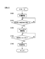
- FIG. 2 is a flowchart showing an example of processing of the control unit 6 at the time of initial charging.
- FIG. 3 is a flowchart showing an example of processing in the charge / discharge operation after the initial charging.
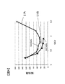
- FIG. 4 is a diagram showing resistance values in each OCV of the assembled battery 2A charged to SOC 90% and the assembled battery 2B charged to SOC 50%.
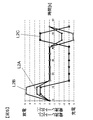
- FIG. 5 is a diagram showing a current rate and a current rate ratio.
- FIG. 1 is a diagram showing an embodiment of a battery system according to the present invention.
- FIG. 2 is a flowchart showing an example of processing of the control unit 6 at the time of initial charging.
- FIG. 3 is a flowchart showing an
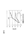
- FIG. 7 is a diagram showing an output ratio when the number ratio is 1: 4 and an output ratio when the number ratio is 2: 3.
- FIG. 8 is a diagram for explaining the second embodiment.
- FIG. 9 is a diagram showing a battery system 1 according to the third embodiment.
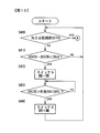
- FIG. 10 is a flowchart illustrating switch control after SOC 90% charging in the third embodiment.
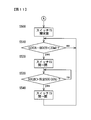
- FIG. 11 is a flowchart illustrating a process when it is determined “yes” in step S400.
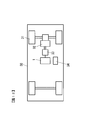
- FIG. 12 is a diagram illustrating an application example of the battery system 1 to an electric vehicle drive system.
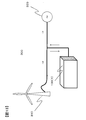
- FIG. 13 is a diagram showing a schematic configuration when the battery system 1 is used in a power generation system 300 using natural energy.
- FIG. 14 is a diagram illustrating an example of a relaxation curve.
- FIG. 15 is a diagram illustrating another example of the battery system 1.
- FIG. 1 is a diagram showing an embodiment of a battery system according to the present invention.
- the battery system 1 includes a plurality of lithium ion secondary batteries 20.
- the lithium ion secondary battery 20 in the present embodiment includes xLi 2 MO 3- (1-x) LiM′O 2 (provided that 0.3 ⁇ x ⁇ 0.7, and M is derived from Mn, Ti, and Zr.
- M ′ is at least one selected from Ni, Co, Mn, Fe, Ti, Zr, Al, Mg, Cr, and V) as a positive electrode active material. ing.
- the present inventor has hysteresis in an open circuit voltage OCV (Open Circuit Voltage) and a resistance value when the SOC changes in a wide range, and a high SOC. It has been found that high resistance and low voltage are obtained after passing through the state. For example, when the SOC is discharged from a charged state where the SOC is approximately 80 to 100% and the SOC is decreased, and when the SOC is increased from the charged state where the SOC is approximately 0 to approximately 20% and the SOC is increased, the SOC is 30%. When the OCV and the resistance in the vicinity of SOC 50% are compared, the OCV is lower and the resistance is higher in the former case.
- OCV Open Circuit Voltage
- a plurality of lithium ion secondary batteries are divided into at least two assembled batteries, the assembled batteries are connected in parallel, and at least one assembled battery is connected to a predetermined SOC ( As a specific example, the control is performed so that the SOC is 50% or less.
- the predetermined SOC defines an SOC that does not cause a decrease in OCV and increase in resistance as described above if a battery is used below this SOC. For example, SOC 50% is used. This value is a characteristic determined by the material of the positive electrode described above, and also depends on the combination with the negative electrode.
- the battery system 1 shown in FIG. 1 includes a plurality of lithium ion secondary batteries 20, ammeters 3a and 3b, voltmeters 4a and 4b, a switch 5 and a control unit 6.
- the plurality of lithium ion secondary batteries 20 are divided into two battery groups connected in parallel.
- One battery group constitutes an assembled battery 2A
- the other battery group constitutes an assembled battery 2B.
- the number of series of the assembled battery 2A and the assembled battery 2B is the same.
- the current value and voltage value of the entire battery system 1 are measured by the ammeter 3a and the voltmeter 4a.
- the ammeter 3b and the voltmeter 4b measure the current value and voltage value of the assembled battery 2B.
- FIG. 1 a portion related to the present invention is shown in the configuration of the battery system 1.
- the load that supplies power from the battery system 1 and the power generation system that supplies power to the battery system 1 are connected to the plus terminal 11a and the minus terminal 11b.
- the assembled battery 2A is connected in series to a line between the terminals 11a and 11b.
- the assembled battery 2B is provided via the switch 5 so that it can be connected in parallel to the assembled battery 2A.
- the switch 5 may be a mechanically opened / closed switch or an electrical switch such as a semiconductor switching element. When the switch 5 is closed, the assembled battery 2B is connected in parallel to the assembled battery 2A. When the switch 5 is opened, the assembled battery 2B is electrically disconnected from the assembled battery 2A, and only the assembled battery 2A is provided between the terminals 11a and 11b. Opening and closing of the switch 5 is controlled by the control unit 6.
- the ratio of the number of batteries of the assembled battery 2A and the number of batteries of the assembled battery 2B is 4: 1.
- the control unit 6 includes a CPU, a memory, and the like, and controls the operation of the switch 5 based on the measured values of the ammeters 3a and 3b and the voltmeters 4a and 4b, a command from the host controller 7, and the like.
- the opening and closing of the switch 5 is controlled by the control unit 6. Basically, when the SOC of the assembled battery 2B is higher than the predetermined SOC described above, the switch 5 is opened and is below the predetermined SOC. In this case, the switch 5 is closed, and the assembled battery 2B is used at a predetermined SOC or lower.
- the predetermined SOC is assumed to be SOC 50%.
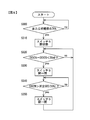
- FIG. 2 is a flowchart showing an example of processing of the control unit 6 at the time of initial charging
- FIG. 3 is a flowchart showing an example of processing in the charge / discharge operation after the initial charging. Which of the processes of FIGS. 2 and 3 is executed is based on a command from the host control device 7.
- the controller 6 calculates the SOC of each assembled battery 2A, 2B as needed based on the current value measured by the ammeters 3a, 3b.
- the SOCs of the assembled batteries 2A and 2B can be calculated by using the integrated value (charge amount and discharge amount) of the current value during charge / discharge and the following equation (1).
- the calculated SOC is stored in a memory provided in the control unit 6. While the battery system is in operation, the control unit 6 calculates the SOC as needed and stores it in the memory.
- SOC [(full charge capacity ⁇ discharge amount + charge amount) / full charge capacity] ⁇ 100 (1)
- step S100 of FIG. 2 charging is started.
- the switch 5 is open when the SOC of the battery pack 2B is SOC> 50%, and is closed when SOC ⁇ 50%. Therefore, when the SOC at the start of charging of the assembled battery 2B is SOC> 50%, only the assembled battery 2A is charged, and when SOC ⁇ 50%, both assembled batteries 2A and 2B are charged. .
- step S110 it is determined whether or not the SOC of the battery pack 2B (described as SOC2B in FIG. 2) is higher than 50% (predetermined SOC). If it is determined that the SOC is higher than 50%, the process proceeds to step S120. 5 is opened. When the SOC of the assembled battery 2B at the start of charging is higher than 50%, the switch 5 has already been opened, so that the opened state is maintained.
- step S110 of the present embodiment the SOC calculated based on the current value of the assembled battery is used to determine the separation of the assembled battery. However, when the OCV of the assembled battery exceeds a predetermined value, the assembled battery is removed. It may be separated. In the case of this embodiment, the OCV corresponding to SOC 50% is about 3.9 V / cell.
- FIG. 14 schematically shows an example of a relaxation curve.
- the horizontal axis represents time, and the vertical axis represents potential (positive electrode potential with respect to the negative electrode of the battery) or current.
- Line L14a indicates a change in current, and line L14b indicates a change in potential.
- a relaxation curve of the lithium ion secondary battery 20 is measured in advance, and an appropriate fitting equation is derived for the relaxation curve.
- the controller 6 estimates the OCV based on the measurement result of the voltmeter at the time of current interruption and the fitting equation.
- step S130 it is determined whether or not the SOC of the assembled battery 2A (described as SOC2A in FIG. 2) exceeds 90%. If it is determined that SOC> 90%, the process proceeds to step S140. Next, charging is stopped in step S140, and a series of charging processes is terminated. By performing this charging process, the assembled battery 2A is charged to SOC 90%, and the assembled battery 2B is charged to SOC 50%.
- FIG. 4 is a diagram showing resistance values in each OCV of one cell (line L1A) of the assembled battery 2A charged to SOC 90% and one cell (line L1B) of the assembled battery 2B charged to SOC 50%. is there.
- line L1A of the assembled battery 2A nine data are shown every 10% between SOC 10% and SOC 90%.
- line L1B of the assembled battery 2B five data are shown for every 10% between SOC 10% and SOC 50%.
- the battery has a high resistance and a low OCV.
- the data of the assembled battery 2A (line L1A) has a higher resistance. High and OCV low.
- step S200 of FIG. 3 the OCV of the assembled battery 2A decreases, and the open circuit voltage (OCV: described as OCV2A in FIG. 2) of the assembled battery 2A and the OCV of the assembled battery 2B (described as OCV2B in FIG. 2). It is determined whether or not the difference (OCV2A-OCV2B) has become smaller than 20 mV.
- the determination value 20 mV is an example, and is set according to the configuration of the assembled batteries 2A and 2B, the use of the battery system, and the like, and is not limited to 20 mV.
- step S210 the switch 5 is switched from the open state to the closed state, and the assembled battery 2B is connected.
- SOC of each assembled battery 2A, 2B at the time of switching is about 70% and about 50%.
- step S220 it is determined whether or not the SOC of the battery pack 2B exceeds 50%. Therefore, after the switch 5 is closed in step S210, charging / discharging is performed using both the assembled batteries 2A and 2B unless the SOC of the assembled battery 2B exceeds 50%.
- the resistance is increased and the OCV is decreased after the high SOC state.
- the predetermined SOC in step S220 is set lower than the SOC in which the resistance is increased. That is, as long as the assembled battery 2B is used between SOC 0% and a predetermined SOC, high resistance and low OCV can be prevented and high power (low resistance) can be used.
- step S210 When the SOC of the battery pack 2B exceeds 50% due to charging after the switch 5 is closed in step S210, it is determined yes in step S220, and the process proceeds to step S230 and the switch 5 is opened. If the process of step S230 is completed, the process returns to step S200. Thereafter, charging and discharging are performed using only the assembled battery 2 ⁇ / b> A until it is determined to be “yes” in step S ⁇ b> 200 by discharging.
- the OCV and resistance of each lithium ion secondary battery 20 of the assembled battery 2A change as shown by the line L1A in FIG. 4, and the OCV and resistance of each lithium ion secondary battery 20 of the assembled battery 2B appear as the line L1B.
- the battery system has a low resistance and a high output.
- FIG. 5 shows that in the battery system 1 to which the assembled battery 2B is connected (that is, the switch 5 is closed), from the state where the OCV is 3.9 V / cell (see FIG. 4), 3C discharge (10 sec) ⁇ no load (30 sec) ⁇ 3C charge (10 sec) and the charge rate of the assembled battery 2A and the assembled battery 2B (line L2A, L2B), and the current rate ratio of the assembled battery 2B to the assembled battery 2A (line L2C) Is shown.
- the assembled battery 2B is charged and discharged at a rate twice as high as that of the assembled battery 2A.
- the SOC changes drastically and the OCV also changes greatly. Therefore, in the no-load state after the 3C rate discharge, the OCV of the assembled battery 2B is lower than the OCV of the assembled battery 2A, and a current flows from the assembled battery 2A to the assembled battery 2B. Since the assembled batteries 2A are arranged in parallel, the current rate ratio at this time is minus 4.
- the assembled battery 2B indicated by the line L3B is discharged at a higher rate than the assembled battery 2A indicated by the line L3A, but thereafter, the rate becomes lower than that of the assembled battery 2A.
- the assembled battery 2B is initially discharged at a high rate, the SOC is greatly reduced, and the OCV is accordingly reduced. Therefore, if the discharge is continued, the current rate of the assembled battery 2B will decrease. Therefore, even when the battery system 1 is continuously discharged at a high rate, the battery system 1 is not extremely discharged only from the assembled battery 2 ⁇ / b> B to be overdischarged.
- the assembled battery 2B has a high SOC due to a control error or the like, so that the resistance is increased. In that case, the resistance can be lowered again by setting the assembled battery 2B to SOC 20% or less once.
- the ratio to the number was 1: 4.
- FIG. 7 compares the case where the number ratio is 1: 4 and the case where the number ratio is 2: 3.
- line L10 shows the output ratio when the number ratio is 1: 4
- line L20 shows the output ratio when the number ratio is 2: 3.
- the horizontal axis indicates the SOC of the assembled battery 2A.
- the following battery system was used as the reference for determining the output ratio. That is, 20 lithium ion secondary batteries 20 are made into one assembled battery without dividing into two assembled batteries 2A and 2B as shown in FIG. 1, and all the lithium ion secondary batteries 20 are charged to SOC 90%. Used for charging and discharging.
- the assembled battery 2B is charged only to SOC 50%, so the total capacity of the assembled batteries 2A and 2B is 90% when all the lithium ion secondary batteries 20 are used up to SOC 90%. become.
- the output in the range of 30% to 70% of SOC (SOC of the assembled battery 2A) is increased by 4% to 19%.
- the range in which the SOC of assembled battery 2A is 30% to 70% corresponds to the range of about 30% to about 50% of SOC of assembled battery 2B.
- the battery system has a low resistance and a high output as shown in FIG. It can be seen that the effect of increasing the output increases as the number of lithium ion secondary batteries 20 to be separated increases, and in order to obtain a sufficient effect, at least 20% or more of the batteries are separated and connected. Is preferred.
- the configuration of the battery system 1 is the same as that shown in FIG.
- the control of the switch 5 for disconnecting and connecting the assembled battery 2B is different from that of the above-described first embodiment.
- the control in the charging / discharging process is changed to the control shown in FIG. 8 instead of the above-described FIG.
- step S300 in FIG. 8 it is determined whether the output at 50% SOC is 70% or less of the initial output. If it is determined that it is 70% or less, the process proceeds to step S310.
- the initial output is an output at the time when the SOC is initially charged to 90%, and the resistance is further increased by repeating the subsequent charging and discharging, and the output decreases.
- the control unit 6 calculates the output of the assembled battery based on the detected current value.
- the output at SOC 50% is used, but the output may not be SOC 50%.
- step S310 the switch 5 is switched to the open state, and the assembled battery 2B is once disconnected.
- step S320 it is determined whether or not the difference between the OCV of the assembled battery 2A and the OCV of the assembled battery 2B has become smaller than 20 mV. If it is determined that the difference ⁇ 20 mV, the process proceeds to step S330. In step 330, the switch 5 is switched from the open state to the closed state.
- step S340 it is determined whether or not the SOC of the battery pack 2B exceeds 50%. And if it determines with yes by step S340, it will progress to step S350 and the switch 5 will be in an open state. Thereafter, the process returns to step S320.
- both the assembled batteries 2A and 2B are used with the switch 5 closed until the output is reduced to 70% of the initial state. That is, it is used with the same capacity as the conventional one. Then, when the output at SOC 50% drops to the initial 70%, connection / separation control of the assembled battery 2A is started in the same manner as in the first embodiment. By performing such control, the assembled battery 2B is used at an SOC of 50% or less, and the resistance can be lowered again.
- FIG. 9 is a diagram illustrating a battery system 1 according to the third embodiment.
- a switch 15, an ammeter 3c, and a voltmeter 4c are further provided to configure a battery group capable of separating the two assembled batteries 2B and 2C. Therefore, the assembled battery 2 ⁇ / b> A is composed of eight lithium ion secondary batteries 20.
- Other configurations are the same as those shown in FIG.
- the initial charging operation is the same as that in the first embodiment. That is, charging is started with the switches 5 and 15 closed, and when the SOC of the assembled battery 2B reaches 50%, the switch 5 is opened and the assembled battery 2B is disconnected. Thereafter, the assembled batteries 2A and 2C are charged to SOC 90%.
- step S400 in FIG. 10 is the same as that in step S300 in FIG. 8, and whether or not the output at 50% SOC of the assembled batteries 2A and 2C used for charging / discharging has become 70% or less of the initial output. Determine. If it is determined that the output has not decreased to 70% of the initial value, the process proceeds to step S410. If it is determined that the output is 70% or less, the process proceeds to the process shown in FIG.
- step S410 it is determined whether or not the difference between the OCV of the assembled battery 2A (or the assembled battery 2C) and the OCV of the assembled battery 2B is less than 20 mV. If it is determined that the difference ⁇ 20 mV, the process proceeds to step S420, and the switch 5 is switched from the open state to the closed state. As a result, the assembled battery 2B is connected to the assembled batteries 2A and 2C. If it is determined no in step S41, the process returns to step S400.
- step S430 it is determined whether or not the SOC of the battery pack 2B exceeds 50%. And if it determines with yes by step S440, it will progress to step S440 and the switch 5 will be in an open state. Thereafter, the process returns to step S400.
- step S400 If it is determined in step S400 that the output at 50% SOC is 70% or less of the initial output, the process proceeds to step S500 in FIG. 11 and the switch 15 is switched to the open state.
- the processing from step S510 to step S540 is the same processing as the processing from step S200 to step S230 shown in FIG. 3 except that the switch for switching between opening and closing is the switch 15. That is, the assembled batteries 2B and 2C are integrally separated and connected to the assembled battery 2A in the same manner as in the first embodiment.
- step S510 it is determined whether or not the difference (OCV2A-OCV2B) between the OCV of the assembled battery 2A and the OCV of the assembled battery 2B (or the assembled battery 2C) is less than 20 mV. If “OCV2A ⁇ OCV2B ⁇ 20 mV” is determined in step S510, the process proceeds to step S520 to switch the switch 15 from the open state to the closed state.
- step S530 it is determined whether or not the SOC of the assembled battery 2B (or the assembled battery 2C) exceeds 50%. If it is determined that the SOC exceeds 50%, the process proceeds to step S540. In step S540, the switch 15 is switched from the closed state to the open state, and the process returns to step S510.
- the switch 5 is switched as in the case of the first embodiment. Separation and connection of the assembled battery 2B are performed.
- the assembled batteries 2A, 2C used from the low SOC to the high SOC are increased in resistance by the charge / discharge cycle and the output becomes 70% or less of the initial value, the assembled battery 2C is also the assembled battery 2B. By performing the same separate connection operation, the resistance of the assembled battery 2C is reduced again.
- the output at SOC 50% was 70% of the initial value. Recovered to 74%. Also in the case of the configuration of the present embodiment, the lifetime can be extended in an application that cannot be used when the output reaches 70%, as in the second embodiment described above.
- the battery control system according to the present invention can be applied to control of any shape of a lithium ion secondary battery such as a cylindrical shape, a flat shape, a square shape, a coin shape, a button shape, and a sheet shape. It is preferable that the negative electrode has a low discharge potential and a high capacity.
- the negative electrode includes lithium metal, carbon having a low discharge potential, Si, Sn having a large weight specific capacity, and lithium titanate (Li 4 Ti 5 having high safety). Various materials such as O 12 ) can be used.
- a lithium ion secondary battery was produced using the above-described positive electrode, negative electrode, separator, and electrolytic solution (electrolyte).
- lithium metal is used for the negative electrode
- a PP (polypropylene) porous ion conductive and insulating separator is used for the separator
- the nonaqueous organic solvent ethylene carbonate (electrolyte) is used as the electrolyte (electrolyte).
- EC ethyl methyl carbonate
- DMC dimethyl carbonate
- the battery system using the lithium ion secondary battery described above can be used as a power source for various devices.
- it is used as a power source for driving a motor in a hybrid railway vehicle that runs with a diesel engine and a motor, an electric vehicle that runs with a motor, a hybrid vehicle that runs with an engine and a motor, and a plug-in hybrid vehicle that can charge a battery from the outside.
- a power source to store electric power extracted from the chemical reaction between hydrogen and oxygen in a fuel cell vehicle, and use it as a power source to supply electric power to a motor
- a robot using a battery as an energy source, a work vehicle such as a forklift It can be used as a power source or applied to various mobile power sources.
- it can be widely applied to electric wheelchairs, various satellites, rockets, submarines, etc.
- FIG. 12 shows an example of application to the drive system of the electric vehicle 30.
- the electric vehicle 30 includes a motor 32 that drives the rear wheel 31, a power converter 33 that converts the DC voltage of the battery system 1 into an AC voltage and supplies power to the motor 32, and a lithium ion battery provided in the battery system 1.
- a battery control unit 34 for monitoring the battery state (charge / discharge state, temperature state, etc.) of the secondary battery 20 is provided.
- the battery control unit 34 corresponds to the host control device 7 shown in FIG.
- the present invention can also be applied to a power storage power source (power storage system) of a power generation system such as wind power generation.
- FIG. 13 shows a schematic configuration when the battery system 1 is used in a power generation system 300 using natural energy.
- power generation is performed using the wind power generation device 310.
- the power generation amount using the natural energy is not limited to the wind power generation device 310. Therefore, in order to realize stable power supply, it is necessary to charge and discharge power from the power storage system (power storage power source) 100 according to the load of the power system 320.
- the power storage system power storage power source
- FIG. 13 by applying the above-described battery system 1 to the power storage system 100, a required output can be obtained with a small number of secondary batteries (lithium ion secondary battery 20), and the cost of the power generation system 300 can be obtained. Can be reduced.
- the power generation system 300 using a solar cell and a wind power generator was illustrated here, application to an electric power storage system is not limited to this,
- the battery system according to the present invention includes xLi 2 MO 3- (1-x) LiM′O 2 (where 0.3 ⁇ x ⁇ 0.7 and M Is at least one selected from Mn, Ti, and Zr, and M ′ is at least one selected from Ni, Co, Mn, Fe, Ti, Zr, Al, Mg, Cr, and V)
- the present invention is applied to a battery system having a battery group composed of a plurality of lithium ion secondary batteries 20 using a solid solution positive electrode active material as a positive electrode.
- the assembled battery 2A as a 1st battery group connected to charging / discharging object and the assembled battery 2B as a 2nd battery group connected in parallel with the assembled battery 2A via the switch 5 are provided.
- the control unit 6 switches the switch 5 from the closed state to the opened state, and the state of charge of the assembled battery 2A is lowered to reduce the open voltage of the assembled battery 2A.
- the switch 5 is switched from the open state to the closed state.
- the lithium ion secondary battery 20 using the positive electrode active material described above has a high resistance and a low OCV when charged to a high SOC state such as SOC 90%. That is, when charge / discharge operation is performed in a wide SOC range, output performance is degraded. Therefore, the SOC that does not cause high resistance and low OCV is set to a predetermined SOC, and when the assembled battery 2B exceeds the predetermined SOC, the switch 5 is opened and disconnected from the circuit. And only the assembled battery 2A was charged to high SOC.
- the switch 5 is closed.
- charging / discharging was performed using both the assembled batteries 2A and 2B.
- the assembled battery 2B does not have a high resistance, it is possible to increase the output at a predetermined SOC or less as compared with a case where the assembled battery 2B is not separated.
- the predetermined SOC is preferably 50%, and the predetermined value is preferably 20 mV.
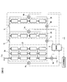
- the plurality of lithium ion secondary batteries 20 are divided into two assembled batteries 2A and 2B, but, for example, divided into five assembled batteries 2A to 2E connected in parallel as shown in FIG. At least one of them may be separated.
- voltmeters 4a to 4e and ammeters 3a to 3e are provided.
- the switches 5c to 5e are closed, the assembled batteries 2A and 2C to 2E are handled as one battery group, and the assembled battery 2B is separated and connected.
- control unit 6 determines whether or not the output of the assembled battery 2A shown in FIG. 1 has decreased by a predetermined ratio (for example, 70%) or more with respect to the initial output, and when it is determined that the output has decreased by a predetermined ratio or more.
- a predetermined ratio for example, 70%
- the above-described switching control of the switch 5 may be started. In the case of such control, it can be used at a higher capacity until the output is reduced by a predetermined rate or more compared to the case where separation control is performed from the beginning as in the first embodiment. Further, when the resistance of the assembled battery 2B is increased and the output is decreased by a predetermined rate or more, it is possible to reduce the resistance of the assembled battery 2B by starting the switching control for separated connection.
- the assembled battery 2A shown in FIG. 1 is further composed of two assembled batteries 2A and 2C connected in parallel, and the assembled battery 2C is electrically connected and disconnected by a switch 15. Can be switched, and the following control may be performed. That is, when the output of the assembled batteries 2A and 2C in the connected state has decreased by a predetermined ratio or more with respect to the initial output, the control unit 6 determines that the charged state of the assembled battery 2B exceeds the predetermined SOC with respect to the switch 5.
- the switch 5 When the switch 5 is switched from the closed state to the open state, the state of charge of the assembled battery 2A is lowered, and the difference between the open voltage of the assembled battery 2A and the open voltage of the assembled battery 2B becomes a predetermined value or less, the switch 5 is opened.
- the switch 15 When the state of charge of the assembled battery 2C exceeds a predetermined SOC, the switch 15 is switched from the closed state to the opened state, and the state of charge of the assembled battery 2A is lowered to open the assembled battery 2A.
- the switch 15 When the difference between the voltage and the open voltage of the assembled battery 2C is equal to or less than a predetermined value, the switch 15 is switched from the open state to the closed state.
- the resistance of the assembled battery 2C can be lowered again, and higher output can be achieved compared to the case where only one assembled battery is separated.
- the present invention is not limited to the above-described embodiments, and various designs can be made without departing from the spirit of the present invention described in the claims. It can be changed.
- the above-described embodiment has been described in detail for easy understanding of the present invention, and is not necessarily limited to one having all the configurations described.
- a part of the configuration of an embodiment can be replaced with the configuration of another embodiment, and the configuration of another embodiment can be added to the configuration of an embodiment.
Landscapes
- Engineering & Computer Science (AREA)
- Power Engineering (AREA)
- Life Sciences & Earth Sciences (AREA)
- Sustainable Development (AREA)
- Sustainable Energy (AREA)
- Transportation (AREA)
- Mechanical Engineering (AREA)
- Secondary Cells (AREA)
- Charge And Discharge Circuits For Batteries Or The Like (AREA)
Abstract
xLi2MO3-(1-x)LiM'O2(但し、0.3<x<0.7であり、MはMn、Ti、Zrから選ばれる少なくとも1種であり、M'はNi、Co、Mn、Fe、Ti、Zr、Al、Mg、Cr、Vから選ばれる少なくとも1種である)で表記される固溶体正極活物質を正極に用いる複数のリチウムイオン二次電池で構成される電池群を有する電池システムにおいて、充放電対象に接続される第1電池群と、第1開閉器を介して第1電池群と並列接続される第2電池群とを備え、第2電池群の充電状態が所定SOCを超えると、第1開閉器を閉状態から開状態に切り換え、第1電池群の充電状態が低下して該第1電池群の開放電圧と第2電池群の開放電圧との差が所定値以下となると、第1開閉器を開状態から閉状態に切り換える。
Description
本発明は、低SOC範囲で使用している場合には高抵抗化せず、高SOC状態を経ると高抵抗するリチウムイオン二次電池を用いた電池システム、およびその電池システムを用いた移動体および電力貯蔵システム、および、その電池システムの制御方法に関する。
近年、地球温暖化の防止や化石燃料の枯渇への懸念から、走行に必要となるエネルギーが少ない電気自動車や、太陽光や風力等の自然エネルギーを利用した発電システムに期待が集まっている。しかしながら、これらの技術には次の技術的課題があり、普及が進んでいない。
電気自動車の課題は、駆動用電池のエネルギー密度が低く、一充電での走行距離が短いことである。一方、自然エネルギーを利用した発電システムの課題は、発電量の変動が大きく、出力の平準化のために大容量の蓄電手段が必要となり、高コストとなる点である。何れの技術においても安価で高エネルギー密度をもつ二次電池が求められている。
リチウムイオン二次電池は、ニッケル水素電池や鉛電池等の他の二次電池に比べて重量当たりのエネルギー密度が高いため、電気自動車や電力貯蔵システムへの応用が期待されている。ただし、電気自動車や電力貯蔵システムの要請に応えるためには、さらなる高エネルギー密度化が必要である。電池の高エネルギー密度化のためには、正極及び負極のエネルギー密度を高める必要がある。
高エネルギー密度の正極活物質として、Li2MO3-LiM’O2固溶体が期待されている。なお、MはMn、Ti、Zrから選ばれる1種類以上の元素であり、M’はNi、Co、Mn、Fe、Ti、Zr、Al、Mg、Cr、Vから選ばれる1種類以上の元素である。以後、Li2MO3-LiM’O2固溶体を固溶体正極活物質と略記する。
層状構造であり電気化学的に不活性なLi2MO3と、層状構造であり電気化学的に活性なLiM’O2とが混合された固溶体は、初回充電時に4.4V(リチウム金属に対して、以後電位はすべてリチウム金属に対する電位を表記)を超える電位で充電することにより活性化して、200mAh/gを超える大きな電気容量を示しうる高容量な正極活物質である(特許文献1参照)。そのため、固溶体正極活物質を用いた電池では高エネルギー密度化が可能となる。
また、非特許文献1には、Li2MO3の割合xが0.1と低い場合、200mAh/gを超えるような高容量が得られず、xが0.3~0.7のときに高い容量が得られることが開示されている。
また、非特許文献2には、Li2MO3だけでは、非常に比表面積を小さくしない限り十分な容量が得られず、高比表面積の場合は劣化が激しいことが開示されている。このため、Li2MO3の割合が高すぎると電極として機能しないので、高容量が得られ、かつ、電極として適切に機能するLi2MO3の割合xは、0.3~0.7の範囲であるものと推定される。
ACS Publication, "Chemistry of Materials", vol.20, pp.6095-6106, 2008
Denis Y. W. Yu, et al., "Electrochemical Activities in Li2MnO3", Journal of the Electrochemical Society 156 (6) A417-A424, The Electrochemical Society, 2009
上述した各引用文献に記載の固溶体正極活物質は、リチウムイオン拡散係数及び電子伝導度が低いため、電極抵抗が高いという問題がある。したがって、固溶体正極活物質を正極に用いた高容量な電池システムの場合、高抵抗なことで高い出力が得られない。特に電位が低下し、抵抗が増大する低SOC(State Of Charge:充電状態)において、低出力となる。
本発明の一の態様によると、電池システムは、xLi2MO3-(1-x)LiM’O2(但し、0.3<x<0.7であり、MはMn、Ti、Zrから選ばれる少なくとも1種であり、M’はNi、Co、Mn、Fe、Ti、Zr、Al、Mg、Cr、Vから選ばれる少なくとも1種である)で表記される固溶体正極活物質を正極に用いる複数のリチウムイオン二次電池で構成される電池群を有するものであって、電池群を構成し、充放電対象に接続される第1電池群と、電池群を構成し、第1開閉器を介して第1電池群と並列接続される第2電池群と、第2電池群の充電状態が所定SOCを超えると、第1開閉器を閉状態から開状態に切り換え、第1電池群の充電状態が低下して該第1電池群の開放電圧と第2電池群の開放電圧との差が所定値以下となると、第1開閉器を開状態から閉状態に切り換える切換制御を行う制御部と、を備える。
本発明の他の態様によると、xLi2MO3-(1-x)LiM’O2(但し、0.3<x<0.7であり、MはMn、Ti、Zrから選ばれる少なくとも1種であり、M’はNi、Co、Mn、Fe、Ti、Zr、Al、Mg、Cr、Vから選ばれる少なくとも1種である)で表記される固溶体正極活物質を正極として用いる複数のリチウムイオン二次電池で構成される電池群を接続および分離可能に複数並列接続して成る電池システムの制御方法であって、複数の電池群の内の少なくとも一つの電池群を、充電状態が所定SOCを超えたならば接続状態から分離状態に切り換え、分離状態時に、分離されていない他の電池群の開放電圧と分離された電池群の開放電圧との差が所定値以下となったならば、分離状態から接続状態に切り換える。
本発明の他の態様によると、xLi2MO3-(1-x)LiM’O2(但し、0.3<x<0.7であり、MはMn、Ti、Zrから選ばれる少なくとも1種であり、M’はNi、Co、Mn、Fe、Ti、Zr、Al、Mg、Cr、Vから選ばれる少なくとも1種である)で表記される固溶体正極活物質を正極として用いる複数のリチウムイオン二次電池で構成される電池群を接続および分離可能に複数並列接続して成る電池システムの制御方法であって、複数の電池群の内の少なくとも一つの電池群を、充電状態が所定SOCを超えたならば接続状態から分離状態に切り換え、分離状態時に、分離されていない他の電池群の開放電圧と分離された電池群の開放電圧との差が所定値以下となったならば、分離状態から接続状態に切り換える。
本発明によれば、電池システムの高出力化を図ることができる。
以下、図を参照して本発明を実施するための形態について説明する。
-第1の実施の形態-
図1は、本発明による電池システムの一実施の形態を示す図である。電池システム1は、複数のリチウムイオン二次電池20を備える。本実施の形態におけるリチウムイオン二次電池20は、xLi2MO3-(1-x)LiM’O2(但し、0.3<x<0.7であり、MはMn、Ti、Zrから選ばれる少なくとも1種であり、M’はNi、Co、Mn、Fe、Ti、Zr、Al、Mg、Cr、Vから選ばれる少なくとも1種である)で表記される固溶体を正極活物質として用いている。
-第1の実施の形態-
図1は、本発明による電池システムの一実施の形態を示す図である。電池システム1は、複数のリチウムイオン二次電池20を備える。本実施の形態におけるリチウムイオン二次電池20は、xLi2MO3-(1-x)LiM’O2(但し、0.3<x<0.7であり、MはMn、Ti、Zrから選ばれる少なくとも1種であり、M’はNi、Co、Mn、Fe、Ti、Zr、Al、Mg、Cr、Vから選ばれる少なくとも1種である)で表記される固溶体を正極活物質として用いている。
本発明者は、このような固溶体正極活物質を用いたリチウムイオン二次電池では、SOCが広範囲で変化したときに、開回路電圧OCV(Open Circuit Voltage)および抵抗値にヒステリシスがあり、高SOC状態を経ると高抵抗および低電圧となることを見出した。例えば、SOCが約80~100%付近の充電状態から放電してSOCを減少させた場合と、SOCが0~約20%付近の充電状態から充電してSOCを増加させた場合における、SOC30%からSOC50%付近でのOCVおよび抵抗を比較すると、前者の場合の方がOCVは低く、抵抗は高くなる。
さらに、このようなOCVの低電圧化および抵抗の高抵抗化は、SOCが上昇して約70%以上の充電状態を経ることで顕著に表れ、逆に、SOC50%以下の充電状態で使用する限りはほとんど現れず、高出力となることを見出した。
これらの知見を基に、本発明では、後述するように複数のリチウムイオン二次電池を少なくとも2つの組電池に分けるとともに、それらの組電池を並列接続し、少なくとも1つの組電池を所定SOC(具体例としてはSOC50%)以下となるように制御するようにした。この所定SOCは、このSOC以下で電池を使用すれば上述したようなOCVの低下および高抵抗化が生じないSOCを規定するものであり、例えば、SOC50%が用いられる。この値は、上述した正極の材質によって決まってくる特性であって、負極との組み合わせにも依存する。
図1に示す電池システム1は、複数のリチウムイオン二次電池20、電流計3a,3b、電圧計4a,4b、スイッチ5および制御部6を備えている。複数のリチウムイオン二次電池20は並列接続される2つの電池群に分けられており、一方の電池群は組電池2Aを構成し、他方の電池群は組電池2Bを構成している。組電池2Aと組電池2Bとは、直列数が同じになっている。電池システム1全体の電流値および電圧値は、電流計3aおよび電圧計4aによって計測される。一方、電流計3bおよび電圧計4bは、組電池2Bの電流値および電圧値を計測する。なお、図1においては、電池システム1の構成の内、本発明に関係する部分を示した。
電池システム1から電力を供給する負荷や、逆に電池システム1に電力を供給する発電システムは、プラス端子11aおよびマイナス端子11bに接続される。組電池2Aは、端子11a,11b間のラインに直列接続されている。一方、組電池2Bは、スイッチ5を介して、組電池2Aに並列接続可能に設けられている。スイッチ5は、機械的に開閉するスイッチでも良いし、半導体スイッチング素子のような電気的なスイッチでも良い。スイッチ5を閉じると、組電池2Bは組電池2Aに並列接続される。スイッチ5を開くと、組電池2Bは、組電池2Aから電気的に切り離され、端子11a,11b間には組電池2Aのみが設けられることになる。スイッチ5の開閉は制御部6によって制御される。
図1に示す例では、組電池2Aの電池本数と組電池2Bの電池本数との比を、4:1とした。制御部6はCPUやメモリ等を有し、電流計3a,3bおよび電圧計4a,4bの計測値や、上位制御装置7からの指令等に基づいてスイッチ5の動作を制御する。
上述したように、スイッチ5の開閉は制御部6によって制御され、基本的には、組電池2BのSOCが上述した所定SOCよりも高い場合にはスイッチ5は開状態とされ、所定SOC以下の場合にはスイッチ5は閉状態とされ、組電池2Bは所定SOC以下で使用される。以下では、所定SOCをSOC50%として説明する。
電池システム1の使用例としては、例えば、電気自動車に使用される二次電池のように一旦ほぼ満充電状態まで充電し、その後、回生充電が途中で行われるものの、主にモータ駆動により放電が行われるような使い方がある。以下では、初期の充電動作における処理と、その後の充放電動作における処理とに分けて説明する。図2は初期充電時における制御部6の処理の一例を示すフローチャートであり、図3は、初期充電後の充放電動作における処理の一例を示すフローチャートである。図2および図3の処理のいずれが実行されるかは、上位制御装置7からの指令に基づく。
制御部6は、電流計3a,3bにより計測された電流値に基づいて、各組電池2A,2BのSOCを随時算出する。組電池2A,2BのSOCは、充放電時の電流値の積算値(充電量および放電量)と次式(1)とを用いることで算出することができる。算出されたSOCは、制御部6に設けられたメモリに記憶される。電池システム稼働中は、制御部6おいてSOCが随時算出され、メモリ内に記憶される。
SOC=[(満充電容量-放電量+充電量)/満充電容量]×100 …(1)
SOC=[(満充電容量-放電量+充電量)/満充電容量]×100 …(1)
まず、初期充電時の処理について説明する。図2のステップS100では、充電を開始する。上述したように、スイッチ5は、組電池2BのSOCがSOC>50%の場合には開状態で、SOC≦50%の場合には閉状態となっている。そのため、組電池2Bの充電開始時のSOCがSOC>50%の場合には組電池2Aのみが充電され、SOC≦50%の場合には両方の組電池2A,2Bに対して充電が行われる。
ステップS110では、組電池2BのSOC(図2ではSOC2Bと記載)が50%(所定SOC)よりも高いか否かを判定し、50%よりも高いと判定されるとステップS120へ進み、スイッチ5が開状態とされる。なお、充電開始時の組電池2BのSOCが50%よりも高い場合には、すでにスイッチ5は開状態となっているので、開状態が維持される。
なお、本実施形態のステップS110では、組電池の電流値に基づいて算出されたSOCを用いて、組電池の切り離しを判断したが、組電池のOCVが所定値を超えた時点で組電池を切り離してもよい。本実施形態の場合、SOC50%に相当するOCVは、約3.9V/セルとなる。
OCVの算出方法の一例としては、例えば、電流遮断時の電位の変化を示す緩和曲線を用いる方法がある。図14は、緩和曲線の一例を模式的に示したものである。横軸は時間であって、縦軸は電位(電池の負極に対する正極の電位)または電流である。ラインL14aは電流変化を示し、ラインL14bは電位の変化を示す。時刻t1において電流が遮断されると、電流値がゼロとなり、電流遮断後の電位はラインL14bに示すような変化を示し、時間の経過と共に求めるべきOCVの値に近づく。本実施の形態の場合、予め、リチウムイオン二次電池20の緩和曲線を実測し、その緩和曲線に対して適切なフィッティング式を導出しておく。制御部6は、電流遮断時の電圧計の計測結果とフィッティング式とに基づいて、OCVを推定する。
ステップS120が実行された後は、スイッチ5は開状態となっているので、充電により組電池2AのみのSOCが上昇する。ステップS130では、組電池2AのSOC(図2ではSOC2Aと記載)が90%を超えたか否かを判定し、SOC>90%と判定した場合にはステップS140へ進む。次いで、ステップS140で充電を停止し、一連の充電処理を終了する。この充電処理を行うことにより、組電池2AはSOC90%まで充電され、組電池2BはSOC50%まで充電されることになる。
図4は、SOC90%まで充電した組電池2Aのうちの1セル(ラインL1A)と、SOC50%まで充電した組電池2Bのうちの1セル(ラインL1B)の各OCVにおける抵抗値を示す図である。組電池2AのラインL1Aの場合には、SOC10%~SOC90%の間で10%毎に9つのデータを示している。一方、組電池2BのラインL1Bの場合には、SOC10%~SOC50%の間で10%毎に5つのデータを示す。上述したように、高SOC間で使用した場合には電池は高抵抗化および低OCV化するため、例えば、SOC50%のデータを比較すると、組電池2A(ラインL1A)のデータの方が抵抗は高く、OCVは低くなっている。
次に、図3を参照しながら充放電動作時のスイッチ5の制御について説明する。ここでの説明は、スイッチ制御に関する説明が主目的なので、スタート時における組電池2A,2BのSOCがそれぞれ90%、50%であるとする。
図2の充電処理後に放電を開始すると、スイッチ5が開状態なので組電池2Aのみが放電され、組電池2AのSOCおよびOCVが低下する。図3のステップS200では、組電池2AのOCVが低下して、組電池2Aの開放電圧(OCV:図2ではOCV2Aと記載する)と組電池2BのOCV(図2ではOCV2Bと記載)との差(OCV2A-OCV2B)が20mVより小さくなったか否かを判定する。なお、判定値20mVは一例であって、これは、組電池2A,2Bの構成や電池システムの用途等に応じて設定されるものであり、20mVに限定されるもではない。
ステップS200において「OCV差<20mV」と判定されると、ステップS210へ進んでスイッチ5を開状態から閉状態に切り替え、組電池2Bを接続する。図4を見ると、切り替え時の各組電池2A,2BのSOCは、約70%および約50%となっている。スイッチ5が閉じた状態では、2つの組電池2A,2Bを用いて放電および充電が行われる。次いで、ステップS220では、組電池2BのSOCが50%を超えたか否かを判定する。そのため、ステップS210でスイッチ5が閉状態とされた後に、組電池2BのSOCが50%を超えない限り、組電池2A,2Bの両方を用いて充放電が行われる。
上述したように、固溶体正極活物質を用いたリチウムイオン二次電池20では、高SOC状態を経ると高抵抗化および低OCV化する。ステップS220における所定SOCは、高抵抗化が生じるSOCよりも低く設定される。すなわち、組電池2BをSOC0%と所定SOCとの間で使用する限り、高抵抗化および低OCV化を防止でき、高出力(低抵抗)で使用することができる。
ステップS210でスイッチ5が閉状態とされた後に、充電により組電池2BのSOCが50%を超えると、ステップS220においてyesと判定され、ステップS230に進んでスイッチ5が開状態とされる。ステップS230の処理が終了したならば、ステップS200へ戻る。その後、放電によりステップS200でyesと判定されるまでは、組電池2Aのみを使用して充放電が行われる。
上述したように、ステップS210でスイッチ5を閉状態にしてから、ステップS230で開状態とされるまでは、組電池2A,2Bの両方を用いて充放電が行われる。その場合、組電池2Aの各リチウムイオン二次電池20のOCV,抵抗は図4のラインL1Aのように変化し、組電池2Bの各リチウムイオン二次電池20のOCV,抵抗はラインL1Bのように変化する。図4に示すように組電池2Bは組電池2Aよりも抵抗が低いため(OCV=3.9Vで約1/2)、全てのリチウムイオン二次電池20をSOC90%まで使用する従来の構成に比べて、電池システムとして低抵抗になり、高出力化する。
図5は、組電池2Bが接続された(すなわち、スイッチ5が閉状態の)電池システム1において、OCVが3.9V/セルの状態(図4参照)から、3C放電(10sec)→無負荷(30sec)→3C充電(10sec)と充放電した場合の、組電池2Aと組電池2Bの電流レート(ラインL2A,L2B)、および、組電池2Bの組電池2Aに対する電流レート比(ラインL2C)を示したものである。
上述したように、OCV=3.9V付近では組電池2Bの抵抗は組電池2Aの抵抗の約1/2であるため、組電池2Bは組電池2Aの約2倍の高レートで充放電される。すなわち、組電池2Bは組電池2Aよりも電流値が大きいため、SOCの変化が激しく、OCVも大きく変化することになる。そのため、3Cレート放電後の無負荷状態においては、組電池2BのOCVは組電池2AのOCVよりも低くなり、組電池2Aから組電池2Bに電流が流れる。組電池2Aは4並列であるため、この時の電流レート比はマイナス4となっている。
図6は、OCV=3.6V/セルの状態から3Cレートで240sec連続放電した際の、組電池2Aおよび組電池2Bの電流レートを示す図である。図6から分かるように、最初の60secの間は、ラインL3Bで示す組電池2BはラインL3Aで示す組電池2Aよりも高いレートで放電されるものの、その後は組電池2Aよりも低レートとなる。組電池2Bは、最初、高レートで放電されるのでSOCが大きく低下し、それに伴いOCVも低下する。そのため、放電を続けると組電池2Bの電流レートが低下することになる。そのため、電池システム1を高レートで連続放電した場合であっても、組電池2Bからのみ極端に放電されて過放電となるようなことはない。
なお、組電池2Bが制御誤差等により高SOCとなり、高抵抗化することが考えられるが、その場合には、いったん組電池2BをSOC20%以下とすることで再度低抵抗化できる。
上述した実施の形態では、図1に示すように、リチウムイオン二次電池20の本数比、すなわち、組電池2Bのリチウムイオン二次電池20の本数と組電池2Aのリチウムイオン二次電池20の本数との比を、1:4とした。
図7は、本数比が1:4の場合と2:3とした場合とを比較したものである。図7において、ラインL10は本数比を1:4とした場合の出力比を示し、ラインL20は本数比を2:3とした場合の出力比を示す。なお、横軸は、組電池2AのSOCを示す。なお、出力比を求める場合の基準となる出力は、次のような電池システムとした。すなわち、20本のリチウムイオン二次電池20を図1のように2つの組電池2A,2Bに分けずに一つの組電池とし、全てのリチウムイオン二次電池20をSOC90%まで充電し、その後の充放電に用いた。
ラインL10の場合には、組電池2BはSOC50%までしか充電しないので、組電池2A,2Bを合わせた全体の容量は、全てのリチウムイオン二次電池20をSOC90%まで使用する場合の90%になる。一方、SOC(組電池2AのSOC)が30%~70%の範囲における出力は、4%~19%増加している。
ラインL20の場合には、本数比が2:3なので全体の容量は80%となるが、SOCが30%~70%の範囲における出力は、7%~37%増加する。なお、図4を参照すると組電池2AのSOCが30%~70%の範囲は、組電池2BのSOCの約30%~約50%に範囲に相当している。
このように、組電池2Bは組電池2Aよりも抵抗が低いため(図4のOCV=3.9Vで約1/2)、全てのリチウムイオン二次電池20をSOC90%まで使用する従来の構成に比べて、電池システムとして低抵抗になり、図7に示すように高出力化する。高出力化の効果は、分離するリチウムイオン二次電池20の数が多いほど高くなることが分かり、十分な効果を得るためには、少なくとも20%以上の電池を分離・接続する構成とするのが好ましい。
-第2の実施の形態-
第2の実施の形態では、電池システム1の構成は、図1に示すものと同様の構成とした。ただし、組電池2Bの接続切り離しをするスイッチ5の制御を、上述した第1の実施の形態と異なるものとする。まず。組電池2A,2Bを充電するモードにおいては、スイッチ5を閉じた状態のまま、両方の組電池2A,2BをSOC90%まで充電する。その後、スイッチ5の閉状態を維持したまま充放電を行う。
第2の実施の形態では、電池システム1の構成は、図1に示すものと同様の構成とした。ただし、組電池2Bの接続切り離しをするスイッチ5の制御を、上述した第1の実施の形態と異なるものとする。まず。組電池2A,2Bを充電するモードにおいては、スイッチ5を閉じた状態のまま、両方の組電池2A,2BをSOC90%まで充電する。その後、スイッチ5の閉状態を維持したまま充放電を行う。
上述したように、SOC90%まで充電した後に、スイッチ5を閉状態のまま充放電を繰り返すことにより、ヒステリシスの影響を含む種々の影響により組電池2A,2Bが高抵抗化する。そこで、本実施形態では、充放電処理における制御を、上述した図3に代えて図8に示すような制御に変更する。
図8のステップS300では、SOC50%における出力が初期出力の70%以下となったか否かを判定する。そして、70%以下であると判定されるとステップS310へ進む。ここで、初期出力とは、最初にSOC90%まで充電した時点における出力であり、その後の充放電を繰り返しによってさらに高抵抗化し、出力が低下する。制御部6は、検出された電流値に基づいて組電池の出力を算出する。ここでは、SOC50%における出力を用いているが、SOC50%でなくても構わない。
ステップS310では、スイッチ5を開状態に切り換えて組電池2Bをいったん切り離す。ステップS320では、組電池2AのOCVと組電池2BのOCVとの差が20mVより小さくなったか否かを判定する。そして、差<20mVと判定されるとステップS330に進む。ステップ330では、スイッチ5を開状態から閉状態に切り換える。
ステップS340では、組電池2BのSOCが50%を超えたか否かを判定する。そして、ステップS340でyesと判定されると、ステップS350に進んでスイッチ5が開状態とされる。その後、ステップS320へ戻る。
このように、本実施の形態では、出力が初期状態の70%に低下するまでは、スイッチ5を閉じた状態で組電池2A,2Bの両方を使用する。すなわち、従来と同様の容量で使用される。そして、SOC50%における出力が初期の70%に低下した時点で、第1の実施の形態と同様に組電池2Aの接続・分離制御を開始するようにした。このような制御を行うことにより、組電池2BはSOC50%以下で使用されるようになり再度低抵抗化を図ることができる。
例えば、SOC90%まで充電し、さらに1Cレートでの充放電サイクルを繰り返すことで高抵抗化した後に、上述の制御を適用した場合、SOC50%における出力が初期の70%であったものが、初期の75%まで回復した。このような制御方法は、出力が70%となった時点で使用不可となる用途において、組電池の寿命を延長することが可能となる。
-第3の実施の形態-
図9は、第3の実施の形態における電池システム1を示す図である。本実施の形態では、スイッチ15、電流計3cおよび電圧計4cをさらに設け、2つの組電池2B,2Cを分離できる電池群として構成した。そのため、組電池2Aは8本のリチウムイオン二次電池20で構成される。その他の構成は、図1に示した構成と同様である。
図9は、第3の実施の形態における電池システム1を示す図である。本実施の形態では、スイッチ15、電流計3cおよび電圧計4cをさらに設け、2つの組電池2B,2Cを分離できる電池群として構成した。そのため、組電池2Aは8本のリチウムイオン二次電池20で構成される。その他の構成は、図1に示した構成と同様である。
初期充電動作については、第1の実施の形態と同様である。すなわち、スイッチ5,15を閉じた状態で充電を開始し、組電池2BのSOCが50%に達した時点でスイッチ5を開状態にし、組電池2Bを切り離す。その後、組電池2A,2CはSOC90%まで充電する。
図10,11は、SOC90%充電後のスイッチ制御を説明するフローチャートである。図10のステップS400における処理は図8のステップS300と同様の処理であって、充放電に用いられている組電池2A,2CのSOC50%における出力が初期出力の70%以下となったか否かを判定する。そして、出力が初期の70%まで低下していないと判定されるとステップS410へ進み、70%以下であると判定されると図11に示す処理に進む。
ステップS410では、組電池2A(組電池2Cでも良い)のOCVと組電池2BのOCVとの差が20mVより小さくなったか否かを判定する。そして、差<20mVと判定されると、ステップS420に進み、スイッチ5を開状態から閉状態に切り換える。その結果、組電池2Bは、組電池2A,2Cに接続される。ステップS41でnoと判定されると、ステップS400へ戻る。
ステップS430では、組電池2BのSOCが50%を超えたか否かを判定する。そして、ステップS440でyesと判定されると、ステップS440に進んでスイッチ5が開状態とされる。その後、ステップS400へ戻る。
ステップS400で、SOC50%における出力が初期出力の70%以下となったと判定されると、図11のステップS500へ進み、スイッチ15を開状態に切り換える。ステップS510からステップS540までの処理は、開閉を切り換えるスイッチがスイッチ15であることを除いて、図3に示したステップS200からステップS230までの処理と同様の処理となる。すなわち、組電池2Aに対する組電池2B,2Cの一体での分離おおよび接続動作が、第1の実施の形態と同様に行われる。
すなわち、ステップS510では、組電池2AのOCVと組電池2B(組電池2Cでも良い)のOCVとの差(OCV2A-OCV2B)が、20mVより小さくなったか否かを判定する。ステップS510で「OCV2A-OCV2B<20mV」と判定されると、ステップS520へ進んでスイッチ15を開状態から閉状態に切り替える。次いで、ステップS530では、組電池2B(組電池2Cでも良い)のSOCが50%を超えたか否かを判定し、SOCが50%を超えたと判定されるとステップS540へ進む。そして、ステップS540でスイッチ15を閉状態から開状態に切り換えた後、ステップS510へ戻る。
このように、本実施の形態では、充放電サイクルにより高抵抗化して図10のステップS400でyesと判定されるまでは、第1の実施の形態の場合と同様に、スイッチ5を切り換えることによる組電池2Bの分離および接続が行われる。そして、低SOCから高SOCまで利用されている組電池2A,2Cが、充放電サイクルにより高抵抗化して出力が初期値の70%以下となった場合には、組電池2Cも組電池2Bと同様の分離接続動作を行うことにより、組電池2Cの再低抵抗化を図るようにする。
例えば、SOC90%まで充電し、さらに1Cレートでの充放電サイクルを繰り返すことで高抵抗化した後に、上述の制御を適用した場合、SOC50%における出力が初期の70%であったものが、初期の74%まで回復した。本実施の形態の構成の場合も、上述した第2の実施の形態と同様の、出力が70%となった時点で使用不可となる用途において、寿命を延長することができる。
次に、上述の実施の形態で使用したリチウムイオン二次電池について説明する。
(固溶体正極活物質を用いた正極の作製)
0.5Li2MnO3-0.5LiNi1/3Co1/3Mn1/3O2で表記できる固溶体正極活物質と、炭素系導電材料と、あらかじめN-メチル-2-ピロジノン(NMP)に溶解させたバインダとを、質量パーセント(%)でそれぞれ85:10:5の割合で混合し、均一に混合されたスラリを厚み20μmのアルミニウム箔の集電体上に塗布した。その後、120℃で乾燥し、プレスにて電極密度が2.3g/cm3になるよう圧縮成形した。
(固溶体正極活物質を用いた正極の作製)
0.5Li2MnO3-0.5LiNi1/3Co1/3Mn1/3O2で表記できる固溶体正極活物質と、炭素系導電材料と、あらかじめN-メチル-2-ピロジノン(NMP)に溶解させたバインダとを、質量パーセント(%)でそれぞれ85:10:5の割合で混合し、均一に混合されたスラリを厚み20μmのアルミニウム箔の集電体上に塗布した。その後、120℃で乾燥し、プレスにて電極密度が2.3g/cm3になるよう圧縮成形した。
(リチウムイオン二次電池の作製)
次に、リチウムイオン二次電池の作製について説明する。本発明に係る電池制御システムは、円筒形、偏平型、角型、コイン型、ボタン型、シート型等何れの形状のリチウムイオン二次電池の制御にも適用できる。負極は放電電位が低く、高容量であるほど好ましく、負極には、リチウム金属、低い放電電位をもつ炭素、重量比容量が大きいSi、Snや、安全性が高いチタン酸リチウム(Li4Ti5O12)等の種々の材料を用いることができる。
次に、リチウムイオン二次電池の作製について説明する。本発明に係る電池制御システムは、円筒形、偏平型、角型、コイン型、ボタン型、シート型等何れの形状のリチウムイオン二次電池の制御にも適用できる。負極は放電電位が低く、高容量であるほど好ましく、負極には、リチウム金属、低い放電電位をもつ炭素、重量比容量が大きいSi、Snや、安全性が高いチタン酸リチウム(Li4Ti5O12)等の種々の材料を用いることができる。
前記した正極と、負極とセパレータと電解液(電解質)とを用いて、リチウムイオン二次電池を作製した。ここでは、負極にリチウム金属を用い、セパレータにはPP(ポリプロピレン)製多孔質のイオン伝導性および絶縁性を有するセパレータを用い、そして、電解液(電解質)として非水性の有機溶媒のエチレンカーボネート(EC)、エチルメチルカーボネート(EMC)、ジメチルカーボネート(DMC)を体積比1:2:2で混合したものに、六フッ化リン酸リチウム(LiPF6)を1mol/L溶解させたものを用いた。
上述したリチウムイオン二次電池を用いた電池システムは、様々な装置の電源として用いることができる。例えば、ディーゼルエンジンとモータとで走行するハイブリッド鉄道車両、モータで走行する電気自動車、エンジンとモータとで走行するハイブリッド自動車、外部から電池に充電できるプラグインハイブリッド自動車等におけるモータ駆動用電源に使用したり、燃料電池自動車において水素と酸素との化学反応から取り出された電力を蓄電し、モータに電力を供給する電源として使用したり、電池をエネルギー源とするロボットや、フォークリフト等の作業車両などの電源として使用したり、各種移動体の電源に適用できる。さらに、電動車椅子、各種衛星、ロケット、潜水艦等、幅広く適用可能である。
図12は、電気自動車30の駆動系への適用例を示したものである。電気自動車30には、後輪31を駆動するモータ32、電池システム1の直流電圧を交流電圧に変換してモータ32に電力を供給する電力変換装置33、電池システム1に設けられたリチウムイオン二次電池20の電池状態(充放電状態や温度状態等を)監視するバッテリ制御部34等が設けられている。バッテリ制御部34は、図1に示した上位制御装置7に対応している。
力行時には電力変換装置33を介して、電池システム1からモータ32に電力が供給され、電気自動車30が駆動される。また、減速時にモータ32により回生された電力が、電力変換装置33を介して、電池システム1のリチウムイオン二次電池20に貯蔵される。上述したように電池システム1では、二次電池の出力密度が向上するので、電気自動車30の駆動系の出力向上を図ることができる。また、充電時の許容電力を大きくできるので、充電時間の短縮を図ることができる。
図12では、電池システム1を移動体の駆動電源として用いる場合を説明したが、電池システム1は、モータ駆動用電源に限らず、太陽光エネルギーを電力に変換する太陽電池や、風力によって発電する風力発電等の発電システムの、電力貯蔵用電源(電力貯蔵システム)にも適用することができる。
図13は、電池システム1を、自然エネルギーを利用した発電システム300に用いた場合の概略構成を示したものである。図13に示す発電システム300では、風力発電装置310を用いて発電を行っているが、風力発電装置310に限らず自然エネルギーを利用した発電システムでは、気象条件によって発電量が大きく変化する。そのため、安定な電力供給を実現するためには、電力系統320の負荷に合わせて電力貯蔵システム(電力貯蔵用電源)100から電力を充放電する必要がある。図13では、この電力貯蔵システム100に対して上述した電池システム1を適用することにより、少ない二次電池(リチウムイオン二次電池20)で必要な出力を得ることができ、発電システム300のコストを低減することができる。
なお、ここでは、太陽電池や風力発電装置を用いた発電システム300を例示したが、電力貯蔵システムへの適用はこれに限定されず、タンカーなどの大型船舶に搭載される電力システムや、工場等の自家発電システムなどの電力貯蔵システムにも、広く適用可能である。
以上説明したように、本発明による電池システムは、図1に示すように、xLi2MO3-(1-x)LiM’O2(但し、0.3<x<0.7であり、MはMn、Ti、Zrから選ばれる少なくとも1種であり、M’はNi、Co、Mn、Fe、Ti、Zr、Al、Mg、Cr、Vから選ばれる少なくとも1種である)で表記される固溶体正極活物質を正極に用いる複数のリチウムイオン二次電池20で構成される電池群を有する電池システムに適用される。そして、充放電対象に接続される第1電池群としての組電池2Aと、スイッチ5を介して組電池2Aと並列接続される第2電池群としての組電池2Bと、を備える。制御部6は、制御部6は、組電池2Bの充電状態が所定SOCを超えると、スイッチ5を閉状態から開状態に切り換え、組電池2Aの充電状態が低下して組電池2Aの開放電圧と組電池2Bの開放電圧との差が所定値以下となると、スイッチ5を開状態から閉状態に切り換える。
上述の正極活物質を用いるリチウムイオン二次電池20は、SOC90%というような高SOC状態まで充電すると高抵抗化および低OCV化することが見出された。すなわち、幅広いSOC範囲で充放電動作を行うと、出力性能が低下する。そこで、高抵抗化、低OCV化が生じないSOCを所定SOCに設定し、組電池2Bについては所定SOCを超えたならばスイッチ5を開いて回路から切り離す。そして、組電池2Aのみを高SOCまで充電するようにした。また、放電により組電池2AのSOCが低下し、組電池2AのOCVと組電池2BのOCVとの差が所定値以下となって両者の電圧がほぼ等しくなったならば、スイッチ5を閉状態にして、両方の組電池2A,2Bを用いて充放電を行うようにした。この場合、組電池2Bは高抵抗化していないので、分離をしない場合に比べて所定SOC以下における高出力化を図ることができる。上述した固溶体正極活物質を用いる場合には、所定SOCとしては50%が好ましく、所定値としては20mVが好ましい。また、高抵抗化の効果を十分得るためには、分離するリチウムイオン二次電池
なお、図1では、複数のリチウムイオン二次電池20を2つの組電池2A,2Bに分けたが、例えば、図15に示すように並列接続された5つの組電池2A~2Eに分けて、その内の少なくとも一つを分離するようにしても良い。各組電池2A~2Eに対応して、電圧計4a~4eおよび電流計3a~3eが設けられている。上述した第1実施形態では、スイッチ5c~5eを閉じた状態にして、組電池2A,2C~2Eを一つの電池群として扱い、組電池2Bを分離および接続する構造とした。
なお、図15に示す構成を用いる場合には、図11のフローチャートのステップS500,S520およびS540の処理におけるスイッチの符号は、15ではなく5aおよび5cに置き換えられる。
また、制御部6は、図1に示す組電池2Aの出力が初期出力に対して所定割合(例えば70%)以上低下したか否かを判定し、所定割合以上低下したと判定された場合に、上述したスイッチ5の切り換え制御を開始するようにしても良い。このような制御の場合、出力が所定割合以上低下するまでは、第1実施形態のように最初から分離制御を行う場合に比べて、高容量で使用することができる。また、組電池2Bが高抵抗化して出力が所定割合以上低下した場合には、分離接続のための切り換え制御を開始することで、組電池2Bの低抵抗化を図ることが可能となる。
また、図1に示す組電池2Aを、図9に示すように、さらに2つの並列接続された2つの組電池2A,2Cで構成するとともに、組電池2Cはスイッチ15により電気的な接続および分離が切り換え可能な構造とし、次のような制御を行っても良い。すなわち、制御部6は、接続状態にある組電池2A,2Cの出力が初期出力に対して所定割合以上低下した場合には、スイッチ5に関しては、組電池2Bの充電状態が所定SOCを超えると、スイッチ5を閉状態から開状態に切り換え、組電池2Aの充電状態が低下して組電池2Aの開放電圧と組電池2Bの開放電圧との差が所定値以下となると、スイッチ5を開状態から閉状態に切り換え、スイッチ15に関しては、組電池2Cの充電状態が所定SOCを超えると、スイッチ15を閉状態から開状態に切り換え、組電池2Aの充電状態が低下して組電池2Aの開放電圧と組電池2Cの開放電圧との差が所定値以下となると、スイッチ15を開状態から閉状態に切り換える。
このような制御を行うことで、組電池2Cも再度低抵抗化することができ、分離される組電池が1つだけの場合に比べて、より高出力化を図ることができる。
以上、本発明の実施形態について詳述したが、本発明は、上述の実施形態に限定されるものではなく、特許請求の範囲に記載された本発明の精神を逸脱しない範囲で、種々の設計変更を行うことができるものである。例えば、前記した実施の形態は本発明を分かりやすく説明するために詳細に説明したものであり、必ずしも説明した全ての構成を備えるものに限定されるものではない。また、ある実施形態の構成の一部を他の実施形態の構成に置き換えることが可能であり、また、ある実施形態の構成に他の実施形態の構成を加えることも可能である。さらに、各実施形態の構成の一部について、他の構成の追加・削除・置換をすることが可能である。
Claims (8)
- xLi2MO3-(1-x)LiM’O2(但し、0.3<x<0.7であり、MはMn、Ti、Zrから選ばれる少なくとも1種であり、M’はNi、Co、Mn、Fe、Ti、Zr、Al、Mg、Cr、Vから選ばれる少なくとも1種である)で表記される固溶体正極活物質を正極に用いる複数のリチウムイオン二次電池で構成される電池群を有する電池システムにおいて、
前記電池群を構成し、充放電対象に接続される第1電池群と、
前記電池群を構成し、第1開閉器を介して前記第1電池群と並列接続される第2電池群と、
前記第2電池群の充電状態が所定SOCを超えると、前記第1開閉器を閉状態から開状態に切り換え、前記第1電池群の充電状態が低下して該第1電池群の開放電圧と前記第2電池群の開放電圧との差が所定値以下となると、前記第1開閉器を開状態から閉状態に切り換える切換制御を行う制御部と、を備える電池システム。 - 請求項1に記載の電池システムにおいて、
前記第1電池群の出力が初期出力に対して所定割合以上低下したか否かを判定する判定部をさらに備え、
前記制御部は、前記判定部により所定割合以上低下したと判定された場合に、前記切換制御を開始する電池システム。 - 請求項1または2に記載の電池システムにおいて、
前記所定SOCをSOC50%とした電池システム。 - 請求項3に記載の電池システムにおいて、
前記第2電池群に含まれるリチウムイオン二次電池の数を、電池システムに用いられるリチウムイオン二次電池の総数の20%以上とした電池システム。 - 請求項1に記載の電池システムにおいて、
前記第1電池群は、充放電対象に接続される第1組電池と、第2開閉器を介して前記第1組電池と並列接続される第2組電池とで構成され、
前記制御部は、
前記第1電池群の出力が初期出力に対して所定割合以上低下していない場合には、前記第2開閉器を閉状態に維持し、
前記第1電池群の出力が初期出力に対して所定割合以上低下した場合には、
前記第2電池群の充電状態が所定SOCを超えると、前記第1開閉器を閉状態から開状態に切り換え、前記第1組電池の充電状態が低下して該第1組電池の開放電圧と前記第2電池群の開放電圧との差が所定値以下となると、前記第1開閉器を開状態から閉状態に切り換え、
前記第2組電池の充電状態が所定SOCを超えると、前記第2開閉器を閉状態から開状態に切り換え、前記第1組電池の充電状態が低下して該第1組電池の開放電圧と前記第2組電池の開放電圧との差が所定値以下となると、前記第2開閉器を開状態から閉状態に切り換える、電池システム。 - 走行用モータと、
請求項1乃至5のいずれか一項に記載の電池システムと、
前記電池システムの電力により前記走行用モータを駆動する駆動部と、を備えた移動体。 - 発電装置からの電力を請求項1乃至5のいずれか一項に記載の電池システムに貯蔵し、前記電池システムに貯蔵された電力を電力系統へ供給する電力貯蔵システム。
- xLi2MO3-(1-x)LiM’O2(但し、0.3<x<0.7であり、MはMn、Ti、Zrから選ばれる少なくとも1種であり、M’はNi、Co、Mn、Fe、Ti、Zr、Al、Mg、Cr、Vから選ばれる少なくとも1種である)で表記される固溶体正極活物質を正極として用いる複数のリチウムイオン二次電池で構成される電池群を接続および分離可能に複数並列接続して成る電池システムの制御方法であって、
前記複数の電池群の内の少なくとも一つの電池群を、充電状態が所定SOCを超えたならば接続状態から分離状態に切り換え、分離状態時に、分離されていない他の電池群の開放電圧と分離された電池群の開放電圧との差が所定値以下となったならば、分離状態から接続状態に切り換える、電池システムの制御方法。
Priority Applications (1)
| Application Number | Priority Date | Filing Date | Title |
|---|---|---|---|
| PCT/JP2013/063372 WO2014184861A1 (ja) | 2013-05-14 | 2013-05-14 | 電池システム、その電池システムを備える移動体および電力貯蔵システム、および電池システムの制御方法 |
Applications Claiming Priority (1)
| Application Number | Priority Date | Filing Date | Title |
|---|---|---|---|
| PCT/JP2013/063372 WO2014184861A1 (ja) | 2013-05-14 | 2013-05-14 | 電池システム、その電池システムを備える移動体および電力貯蔵システム、および電池システムの制御方法 |
Publications (1)
| Publication Number | Publication Date |
|---|---|
| WO2014184861A1 true WO2014184861A1 (ja) | 2014-11-20 |
Family
ID=51897882
Family Applications (1)
| Application Number | Title | Priority Date | Filing Date |
|---|---|---|---|
| PCT/JP2013/063372 WO2014184861A1 (ja) | 2013-05-14 | 2013-05-14 | 電池システム、その電池システムを備える移動体および電力貯蔵システム、および電池システムの制御方法 |
Country Status (1)
| Country | Link |
|---|---|
| WO (1) | WO2014184861A1 (ja) |
Cited By (3)
| Publication number | Priority date | Publication date | Assignee | Title |
|---|---|---|---|---|
| CN106981895A (zh) * | 2016-01-19 | 2017-07-25 | 铃木株式会社 | 车辆的充放电装置 |
| CN107346830A (zh) * | 2016-05-06 | 2017-11-14 | 大连融科储能技术发展有限公司 | 液流电池控制方法及其装置、液流电池 |
| CN112798968A (zh) * | 2020-12-24 | 2021-05-14 | 重庆峘能电动车科技有限公司 | 电池并联方法、估算电池并联系统soc的方法及相关设备 |
Citations (5)
| Publication number | Priority date | Publication date | Assignee | Title |
|---|---|---|---|---|
| JPH09308013A (ja) * | 1996-05-08 | 1997-11-28 | Toyota Motor Corp | 電気自動車の電源装置 |
| JP2006121874A (ja) * | 2004-10-25 | 2006-05-11 | Nissan Motor Co Ltd | 電源装置およびこれを搭載した車両 |
| JP2011223839A (ja) * | 2010-04-14 | 2011-11-04 | Calsonic Kansei Corp | 車両の電源装置 |
| WO2012127796A1 (ja) * | 2011-03-22 | 2012-09-27 | 株式会社豊田自動織機 | リチウム含有複合酸化物の製造方法、正極活物質および二次電池 |
| JP2013031310A (ja) * | 2011-07-29 | 2013-02-07 | Sanyo Electric Co Ltd | 制御装置、バッテリシステム、電動車両、移動体、電力貯蔵装置および電源装置 |
-
2013
- 2013-05-14 WO PCT/JP2013/063372 patent/WO2014184861A1/ja active Application Filing
Patent Citations (5)
| Publication number | Priority date | Publication date | Assignee | Title |
|---|---|---|---|---|
| JPH09308013A (ja) * | 1996-05-08 | 1997-11-28 | Toyota Motor Corp | 電気自動車の電源装置 |
| JP2006121874A (ja) * | 2004-10-25 | 2006-05-11 | Nissan Motor Co Ltd | 電源装置およびこれを搭載した車両 |
| JP2011223839A (ja) * | 2010-04-14 | 2011-11-04 | Calsonic Kansei Corp | 車両の電源装置 |
| WO2012127796A1 (ja) * | 2011-03-22 | 2012-09-27 | 株式会社豊田自動織機 | リチウム含有複合酸化物の製造方法、正極活物質および二次電池 |
| JP2013031310A (ja) * | 2011-07-29 | 2013-02-07 | Sanyo Electric Co Ltd | 制御装置、バッテリシステム、電動車両、移動体、電力貯蔵装置および電源装置 |
Cited By (4)
| Publication number | Priority date | Publication date | Assignee | Title |
|---|---|---|---|---|
| CN106981895A (zh) * | 2016-01-19 | 2017-07-25 | 铃木株式会社 | 车辆的充放电装置 |
| CN106981895B (zh) * | 2016-01-19 | 2019-12-13 | 铃木株式会社 | 车辆的充放电装置 |
| CN107346830A (zh) * | 2016-05-06 | 2017-11-14 | 大连融科储能技术发展有限公司 | 液流电池控制方法及其装置、液流电池 |
| CN112798968A (zh) * | 2020-12-24 | 2021-05-14 | 重庆峘能电动车科技有限公司 | 电池并联方法、估算电池并联系统soc的方法及相关设备 |
Similar Documents
| Publication | Publication Date | Title |
|---|---|---|
| KR100903244B1 (ko) | 조전지 시스템, 조전지의 충전 방법 및 충전식 청소기 | |
| US8047316B2 (en) | Storage battery system, on-vehicle power supply system, vehicle and method for charging storage battery system | |
| JP5109619B2 (ja) | 組電池システム、及び充放電制御方法 | |
| CN107851855B (zh) | 用于二次电池的补充负电极 | |
| JP4492683B2 (ja) | 電池システム | |
| JP5191502B2 (ja) | リチウムイオン二次電池システムおよびリチウムイオン二次電池 | |
| US11594777B2 (en) | Dual energy storage system and starter battery module | |
| JP2013019709A (ja) | 二次電池システム及び車両 | |
| JP2009072039A (ja) | 電源システム | |
| JP6368948B2 (ja) | 蓄電システム、移動機構、搬送機構、車両及び自動車 | |
| Zhang | Status, opportunities, and challenges of electrochemical energy storage | |
| JP4714229B2 (ja) | リチウム二次電池 | |
| JP2021082426A (ja) | 電池の充電方法および充電システム | |
| CN103718351A (zh) | 高容量正极活性材料和包含其的锂二次电池 | |
| US20160111727A1 (en) | Metal-Ion Battery with Offset Potential Material | |
| WO2019093654A1 (ko) | 배터리 층전 방법 및 배터리 층전 장치 | |
| US20180254529A1 (en) | Lithium replenishment for containing capacity loss in li ion batteries | |
| JP5503957B2 (ja) | 車両用電源装置 | |
| WO2014184861A1 (ja) | 電池システム、その電池システムを備える移動体および電力貯蔵システム、および電池システムの制御方法 | |
| JP5923831B2 (ja) | リチウムイオン二次電池制御システム、電池システム、並びにこれを備える移動体及び電力貯蔵システム | |
| US20190288329A1 (en) | Secondary battery system and secondary battery control method | |
| US7353894B2 (en) | Sealed nickel-metal hydride storage cells and hybrid electric having the storage cells | |
| WO2021186777A1 (ja) | 容量回復装置、二次電池の製造方法、容量回復方法および二次電池システム | |
| WO2014128904A1 (ja) | 電池制御回路、電池システム、並びにこれを備える移動体及び電力貯蔵システム | |
| JP2007166698A (ja) | 充電式電源装置 |
Legal Events
| Date | Code | Title | Description |
|---|---|---|---|
| 121 | Ep: the epo has been informed by wipo that ep was designated in this application |
Ref document number: 13884389 Country of ref document: EP Kind code of ref document: A1 |
|
| NENP | Non-entry into the national phase |
Ref country code: DE |
|
| 122 | Ep: pct application non-entry in european phase |
Ref document number: 13884389 Country of ref document: EP Kind code of ref document: A1 |
|
| NENP | Non-entry into the national phase |
Ref country code: JP |