WO2022091174A1 - 画像表示装置、及び、画像表示方法 - Google Patents
画像表示装置、及び、画像表示方法 Download PDFInfo
- Publication number
- WO2022091174A1 WO2022091174A1 PCT/JP2020/040072 JP2020040072W WO2022091174A1 WO 2022091174 A1 WO2022091174 A1 WO 2022091174A1 JP 2020040072 W JP2020040072 W JP 2020040072W WO 2022091174 A1 WO2022091174 A1 WO 2022091174A1
- Authority
- WO
- WIPO (PCT)
- Prior art keywords
- image
- section
- vertical cross
- display device
- biological tube
- Prior art date
Links
Images


Classifications
-
- A—HUMAN NECESSITIES
- A61—MEDICAL OR VETERINARY SCIENCE; HYGIENE
- A61B—DIAGNOSIS; SURGERY; IDENTIFICATION
- A61B8/00—Diagnosis using ultrasonic, sonic or infrasonic waves
- A61B8/46—Ultrasonic, sonic or infrasonic diagnostic devices with special arrangements for interfacing with the operator or the patient
- A61B8/461—Displaying means of special interest
- A61B8/466—Displaying means of special interest adapted to display 3D data
-
- A—HUMAN NECESSITIES
- A61—MEDICAL OR VETERINARY SCIENCE; HYGIENE
- A61B—DIAGNOSIS; SURGERY; IDENTIFICATION
- A61B8/00—Diagnosis using ultrasonic, sonic or infrasonic waves
- A61B8/08—Detecting organic movements or changes, e.g. tumours, cysts, swellings
- A61B8/0833—Detecting organic movements or changes, e.g. tumours, cysts, swellings involving detecting or locating foreign bodies or organic structures
- A61B8/0841—Detecting organic movements or changes, e.g. tumours, cysts, swellings involving detecting or locating foreign bodies or organic structures for locating instruments
-
- A—HUMAN NECESSITIES
- A61—MEDICAL OR VETERINARY SCIENCE; HYGIENE
- A61B—DIAGNOSIS; SURGERY; IDENTIFICATION
- A61B8/00—Diagnosis using ultrasonic, sonic or infrasonic waves
- A61B8/42—Details of probe positioning or probe attachment to the patient
- A61B8/4209—Details of probe positioning or probe attachment to the patient by using holders, e.g. positioning frames
- A61B8/4227—Details of probe positioning or probe attachment to the patient by using holders, e.g. positioning frames characterised by straps, belts, cuffs or braces
-
- A—HUMAN NECESSITIES
- A61—MEDICAL OR VETERINARY SCIENCE; HYGIENE
- A61B—DIAGNOSIS; SURGERY; IDENTIFICATION
- A61B8/00—Diagnosis using ultrasonic, sonic or infrasonic waves
- A61B8/44—Constructional features of the ultrasonic, sonic or infrasonic diagnostic device
- A61B8/4477—Constructional features of the ultrasonic, sonic or infrasonic diagnostic device using several separate ultrasound transducers or probes
-
- A—HUMAN NECESSITIES
- A61—MEDICAL OR VETERINARY SCIENCE; HYGIENE
- A61B—DIAGNOSIS; SURGERY; IDENTIFICATION
- A61B8/00—Diagnosis using ultrasonic, sonic or infrasonic waves
- A61B8/44—Constructional features of the ultrasonic, sonic or infrasonic diagnostic device
- A61B8/4483—Constructional features of the ultrasonic, sonic or infrasonic diagnostic device characterised by features of the ultrasound transducer
- A61B8/4494—Constructional features of the ultrasonic, sonic or infrasonic diagnostic device characterised by features of the ultrasound transducer characterised by the arrangement of the transducer elements
-
- A—HUMAN NECESSITIES
- A61—MEDICAL OR VETERINARY SCIENCE; HYGIENE
- A61B—DIAGNOSIS; SURGERY; IDENTIFICATION
- A61B8/00—Diagnosis using ultrasonic, sonic or infrasonic waves
- A61B8/46—Ultrasonic, sonic or infrasonic diagnostic devices with special arrangements for interfacing with the operator or the patient
- A61B8/461—Displaying means of special interest
- A61B8/463—Displaying means of special interest characterised by displaying multiple images or images and diagnostic data on one display
-
- A—HUMAN NECESSITIES
- A61—MEDICAL OR VETERINARY SCIENCE; HYGIENE
- A61B—DIAGNOSIS; SURGERY; IDENTIFICATION
- A61B8/00—Diagnosis using ultrasonic, sonic or infrasonic waves
- A61B8/48—Diagnostic techniques
- A61B8/483—Diagnostic techniques involving the acquisition of a 3D volume of data
-
- A—HUMAN NECESSITIES
- A61—MEDICAL OR VETERINARY SCIENCE; HYGIENE
- A61B—DIAGNOSIS; SURGERY; IDENTIFICATION
- A61B8/00—Diagnosis using ultrasonic, sonic or infrasonic waves
- A61B8/52—Devices using data or image processing specially adapted for diagnosis using ultrasonic, sonic or infrasonic waves
- A61B8/5207—Devices using data or image processing specially adapted for diagnosis using ultrasonic, sonic or infrasonic waves involving processing of raw data to produce diagnostic data, e.g. for generating an image
Definitions
- the present invention relates to an image display device and an image display method.
- ultrasonic sensors also referred to as “ultrasonic oscillator”, “piezoelectric body”, “ultrasonic transmitting / receiving element”, and “ultrasonic element"
- ultrasonic sensors are arranged on a sheet-shaped fixing member.
- a diagnostic device that acquires information on the inside of a human body using ultrasonic waves from the body surface of the human body is disclosed.
- Japanese Unexamined Patent Publication No. 2006-247214 Japanese Unexamined Patent Publication No. 58-22406 Japanese Unexamined Patent Publication No. 2006-51105 Japanese Unexamined Patent Publication No. 2010-269060
- Patent Documents 1 to 4 can only specify the position of a living tube (for example, a blood vessel) inside the human body, and can determine the state of the living tube and the positional relationship between the living tube and a medical device. It cannot be presented to the surgeon. Therefore, the techniques described in Patent Documents 1 to 4 still have a problem that it is necessary to rely on the sense of the operator when pushing the medical device in the living lumen.
- each organ biological tube
- vascular system vascular system
- lymph gland system biliary system
- urinary tract system airway system
- digestive system secretory gland and reproductive organ.
- medical devices such as catheters, guide wires, and endoscopes.
- the present invention has been made to solve at least a part of the above-mentioned problems, and an object of the present invention is to provide an image display device capable of presenting the state of a living tube to an operator.
- the present invention has been made to solve at least a part of the above-mentioned problems, and can be realized as the following forms.
- an image display device uses a plurality of ultrasonic sensors to acquire three-dimensional image information inside the human body including the biological tube from the human body, and cross-sectional information of the biological tube included in the three-dimensional image information.
- the position specifying unit identifies the position where the width of the vertical cross section of the biological tube is maximum in the biological tube by using the cross-sectional information of the biological tube included in the three-dimensional image information, and generates an image.
- the unit generates an image showing the vertical cross section of the biological tube at the position specified by the position specifying unit, and the display unit displays the image generated by the image generating unit. Therefore, the surgeon can know the state of the living tube by referring to the image showing the vertical cross section of the living tube displayed on the display unit. As a result, it is possible to provide an image display device capable of presenting the state of the living tube to the operator.
- the medical device in order to prevent a medical device such as a catheter from coming into contact with the inner wall of the biological tube and to suppress damage to a biological tissue (for example, a blood vessel wall), the medical device is positioned near the center of the biological tube.
- the image displayed on the display unit is the vertical cross section of the biological tube at the position where the width of the vertical cross section of the biological tube is maximum, in other words, the biological tube including the center of the biological tube. Represents the vertical section of. Therefore, the surgeon can know the state of the living tube corresponding to the position where the medical device is to be passed.
- the three-dimensional image information includes the three-dimensional image information of the medical device inserted into the biological lumen, and the image generation unit specifies the position.
- the image generation unit specifies the position.
- an image including the vertical cross section of the biological tube and the medical device is generated, and the medical treatment is performed at the position specified by the position specifying part.
- an image may be generated that includes a longitudinal section of the biological tube and does not include the medical device.
- the image generation unit generates and locates an image including the vertical cross section of the biological tube and the medical device when the medical device is present at the position specified by the position identification unit.
- the surgeon can know the positional relationship between the biological tube and the medical device depending on whether or not the image displayed on the display unit includes the medical device. Specifically, the surgeon says that if the image contains the medical device, the medical device is present at the position where the width of the vertical cross section of the biological tube is maximized (in other words, the living lumen). The medical device is located near the center of the In addition, the surgeon said that if the image does not include the medical device, the medical device does not exist at the position where the width of the vertical cross section of the biological tube is maximized (in other words, near the inner wall of the biological tube). You can see that the medical device is close). As a result, according to this configuration, it is possible to provide an image display device capable of presenting to the operator the positional relationship between the biological tube and the medical device in addition to the state of the biological tube.
- the plurality of ultrasonic sensors may be arranged so as to surround the human body. According to this configuration, since the plurality of ultrasonic sensors are arranged so as to surround the human body, the acquisition unit can acquire the three-dimensional image information of the entire range surrounded by the ultrasonic sensors. As a result, the image display device can determine an arbitrary biological tube from the entire range and generate and display an image showing a vertical cross section of the biological tube.
- the plurality of ultrasonic sensors may be ultrasonic elements arranged inside the entire circumference of the band-shaped body that covers the circumference of the human body. According to this configuration, since the plurality of ultrasonic sensors are arranged inside the entire circumference of the band-shaped body that surrounds the human body, they can be easily attached and detached to the patient, and the patient's physique (body size) can be easily attached and detached. ) Can be used.
- the position specifying unit specifies a position where the width of the vertical cross section of the living tube is maximum at a plurality of positions of the living tube, and the image generating unit is said.
- An image showing a vertical cross section of the biological tube at a plurality of positions specified by the position specifying unit may be generated.
- the position specifying unit identifies the position where the width of the vertical cross section of the biological tube is maximum at the plurality of positions of the biological tube, and the image generation unit represents the vertical cross section of the biological tube at the plurality of positions.
- Generate an image As a result, the image display device generates an image showing the vertical cross section of the living tube regardless of the shape of the living tube by appropriately setting the position according to the shape of the living tube (for example, bending, branching, etc.). And can be displayed.
- the present invention can be realized in various aspects, for example, an image generation device for generating an image for display, an image generation method, a medical system including an image display device, and a method for manufacturing these devices and systems. , It can be realized in the form of a computer program or the like that realizes the functions of these devices and systems.
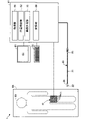
- FIG. 1 is an explanatory diagram illustrating the configuration of the image display device 1 of the first embodiment.
- the image display device 1 is a device that uses ultrasonic waves to generate and display an image showing a vertical cross section of a biological tube of a human body 90.
- the blood vessel of the human body 90 will be illustrated as an example of the biological tube.
- the biological tube may include a lymphatic system, a biliary system, a urinary tract system, an airway system, a digestive system, a secretory gland, a reproductive organ, and the like, in addition to the vascular system.
- the image display device 1 can be used in combination with a medical device.
- the catheter 20 will be illustrated as an example of a medical device.
- the medical device in addition to the catheter 20, any device such as a guide wire can be adopted.
- the image display device 1 includes an ultrasonic sensor array 10, a computer 50, a display unit 60, and an operation unit 70.
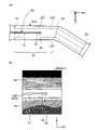
- FIG. 2 is an explanatory diagram illustrating the configuration of the ultrasonic sensor array 10.
- the ultrasonic sensor array 10 has a plurality of ultrasonic sensors 11, and is used to acquire three-dimensional image information inside the human body 90 including a biological tube.
- the ultrasonic sensor array 10 includes a plurality of ultrasonic sensors 11, a band-shaped body 12, and a band 13.
- the ultrasonic sensor 11 emits ultrasonic waves toward the living tissue inside the human body 90, and receives the ultrasonic waves propagated through the living tissue and reflected by the ultrasonic probe (ultrasonic transducer, piezoelectric body, ultrasonic wave). It is also called a transmission / reception element or an ultrasonic element).
- the plurality of ultrasonic sensors 11 are arranged in a grid pattern of n rows and m columns (n and m are arbitrary natural numbers) over the entire one surface side of the strip-shaped body 12.
- the surface on the side where the ultrasonic sensor 11 is arranged is also referred to as an “inner surface”, and the surface opposite to the inner surface is also referred to as an “outer surface”.
- the ultrasonic sensor in the 1st row and 1st column is E11
- the ultrasonic sensor in the 1st row and 2nd column is E12
- the ultrasonic sensor in the 1st row and mth column is E1m
- the sensor is represented as an Enm.
- the ultrasonic sensors 11 are regularly arranged in a grid of n rows and m columns, they may be arranged irregularly.
- the band-shaped body 12 is a band-shaped member having flexibility and elasticity, and is formed of, for example, rubber, synthetic resin, cloth, or the like.
- the operator wraps the inner surface of the band-shaped body 12 (the surface on the side where the ultrasonic sensor 11 is arranged) around the human body 90 lying on the sleeper 95 in a state of facing the body surface side of the human body 90.
- a plurality of ultrasonic sensors 11 can be arranged so as to surround the human body 90.
- the band-shaped body 12 is wrapped around the thigh of the human body 90.
- the band-shaped body 12 may be wrapped around an arbitrary position such as the chest, waist, arms, neck, and around the head. Further, the band-shaped body 12 is wrapped around the body surface (skin) of the human body 90 through the lubricant.
- the band 13 is a band-shaped small piece attached to one short side of the band-shaped body 12, and is formed of, for example, rubber, synthetic resin, cloth, or the like.
- the band 13 is provided with metal fittings for fixing, magic tape, or the like, and can be fixed in a state where the band-shaped body 12 is wound around the human body 90.
- the catheter 20 is a medical device that is inserted into the lumen (intravascular) of the human body 90 and used for treatment or examination.
- the catheter 20 includes a shaft 21, a tip tip 22, a connector 23, and a marker 24.
- the shaft 21 is a hollow member having a long outer shape.
- the tip tip 22 is a flexible member attached to the tip of the shaft 21.
- the connector 23 is a member provided at the base end of the shaft 21 and is a member used by the operator when gripping the catheter 20.
- the marker 24 is a radiation-impermeable member provided between the shaft 21 and the tip 22.
- the configuration of the catheter 20 shown in FIG. 1 is merely an example, and any configuration can be adopted.
- the tip tip 22 and the marker 24 may be omitted.
- a guide wire or the like may be used instead of the catheter 20.
- the display unit 60 is a liquid crystal display provided with a display screen 61.
- the display unit 60 functions as a "display unit” that displays an image generated by the image generation unit 53, which will be described later.
- the display unit 60 may be configured by a display device other than the liquid crystal display (for example, smart glasses, a projector, etc.).
- the operation unit 70 is a keyboard and a mouse for inputting information to the computer 50.
- the operation unit 70 may be configured by an input device other than a keyboard and a mouse (for example, a microphone for acquiring voice input, a touch panel, a foot switch, etc.).
- the computer 50 is a device that controls the entire image display device 1.
- the computer 50 includes a CPU (Central Processing Unit), a ROM (Read Only Memory), and a RAM (Random access memory), and the acquisition unit is obtained by the CPU executing a computer program stored in the ROM. It functions as 51, a position specifying unit 52, and an image generation unit 53. Further, the computer 50 includes a hard disk, a flash memory, a memory card, and the like that function as a storage unit 59.
- the computer 50 is electrically connected to each of the ultrasonic sensor array 10, the display unit 60, and the operation unit 70.
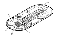
- FIG. 3 is an explanatory diagram of the three-dimensional image information Ics of the human body 90.
- the acquisition unit 51 acquires three-dimensional image information Ics inside the human body including the blood vessel 91 from the human body 90 by using the ultrasonic sensors 11 (E11 to Enm) of the ultrasonic sensor array 10 wound around the human body 90.
- the three-dimensional image information Ics is information representing the three-dimensional internal structure of the human body 90.
- the three-dimensional image information Ics includes the relative three-dimensional positions of each biological tissue inside the human body 90 such as blood vessels 91, bone 92, muscle 93, and fat 94, and the three-dimensional shape of each biological tissue.
- the blood vessel 91 corresponds to a "living body tube". Further, although not shown in FIG.
- the three-dimensional image information Ics is the three-dimensional image of the catheter 20 inside the human body 90.
- the position and the three-dimensional shape of the catheter 20 are included.
- the three-dimensional image information Ics may include a biological tube different from the blood vessel 91, such as a lymphatic vessel.
- the acquisition unit 51 controls the transmission timing of ultrasonic waves in a plurality of ultrasonic sensors 11 (E11 to Enm), and ultrasonic waves are emitted for each sensor such as ultrasonic sensors E11, E12, E13, ..., Enm. Shift the transmission timing of. Then, since the timing of the ultrasonic waves (reflected waves) received by each sensor is also shifted, the acquisition unit 51 can acquire the reflected waves having the intensity corresponding to each position of the ultrasonic sensors E11 to Enm.
- Each living tissue inside the human body 90 has a different acoustic impedance value for each tissue such as blood vessel 91, bone 92, muscle 93, and fat 94.
- the acquisition unit 51 determines the distribution of biological tissues inside the human body 90 (blood vessels 91, bone 92, muscle 93, fat 94, etc.). Distribution) can be acquired, and the three-dimensional image information Ics shown in FIG. 3 can be generated.
- FIG. 4 is an explanatory diagram of the blood vessel 91 included in the three-dimensional image information Ics.
- FIG. 4 illustrates the XYZ axes that are orthogonal to each other.
- the X-axis corresponds to the length direction of the blood vessel 91
- the Y-axis and the Z-axis correspond to the width direction of the blood vessel 91.
- the position specifying unit 52 identifies the position where the width of the vertical cross section of the blood vessel 91 is maximum from the three-dimensional image information Ics.
- the position specifying unit 52 identifies the blood vessel 91 to be displayed as an image from the three-dimensional image information Ics.
- FIG. 4 shows an example of the blood vessel 91 specified by the position specifying unit 52.
- the identification of the blood vessel 91 can be realized by the designation of the operator via the operation unit 70. Further, the blood vessel 91 may be automatically specified by pattern matching between the shape of each biological tissue included in the three-dimensional image information Ics and the shape stored in the storage unit 59 in advance.
- the position specifying unit 52 acquires the cross section of the blood vessel 91 from an arbitrary position of the specified blood vessel 91. In the example of FIG.
- the position specifying portion 52 acquires three cross sections, that is, the cross section C2 at the substantially center of the blood vessel 91 and the cross sections C1 and C3 located in the ⁇ X-axis direction of the cross section C2. are doing.
- the position of the cross section acquired by the position specifying unit 52 and the number of cross sections can be arbitrarily changed.
- the position specifying portion 52 may acquire only one cross section from the blood vessel 91.
- FIG. 5 is a diagram illustrating the processing of the position specifying unit 52.
- the YZ axis of FIG. 5 corresponds to the YZ axis of FIG. 4, respectively.
- the position specifying unit 52 identifies a position in the blood vessel 91 where the width of the vertical cross section of the blood vessel 91 is maximum by using the acquired cross sections C1 to C3.
- the position specifying unit 52 has the maximum width (in the example of FIG. 5, in the example of FIG. 5) from the widths H1 to Hx (x is an arbitrary natural number) in the Y-axis direction for each of the acquired cross sections C1 to C3. Width H2) is specified.
- the position of the width H2 specified here corresponds to the position where the width of the vertical cross section of the blood vessel 91 is maximized. Note that FIG. 5 shows only the widths H1, H2, and H3 of the widths H1 to Hx in the Y-axis direction for the cross sections C1 to C3.
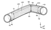
- FIG. 6 and 7 are diagrams illustrating the processing of the image generation unit 53.
- the XYZ axes of FIG. 6 correspond to the XYZ axes of FIG. 4, respectively.
- the image generation unit 53 views the vertical cross section LS2 of the blood vessel 91 at the position specified by the position specifying section 52 (that is, the position of the width H2 where the width in the Y-axis direction is maximum for each of the cross sections C1 to C3). Generate an image to represent.
- the image generation unit 53 is an ultrasonic sensor 11x (FIG. 7) at a position corresponding to the vertical cross section LS2 among the plurality of ultrasonic sensors 11 (E11 to Enm) of the ultrasonic sensor array 10 shown in FIG.
- the reflected wave received from the rectangular frame is used to generate a two-dimensional image with shades of gradation according to the intensity of the reflected wave of each ultrasonic sensor 11x. Then, the image generation unit 53 causes the display unit 60 to display the generated image.
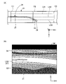
- FIG. 8 is a diagram showing an example of an image displayed on the display unit 60.
- FIG. 8A shows the positional relationship between the blood vessel 91 and the catheter 20 as seen from the Y-axis direction
- FIG. 8B shows an example of the image IM displayed on the display unit 60 at that time.
- the image IM is a two-dimensional image representing an XY plane including a vertical cross section LS2.
- the image IM representing the longitudinal section LS2 of the blood vessel 91 includes the catheter 20 (shaft 21, marker 24, and tip). Chip 22) is included.
- the image IM also includes other biological tissues such as muscle 93 and fat 94.
- FIG. 9 is a diagram showing another example of the image displayed on the display unit 60.
- the configurations of FIGS. 9A and 9B are the same as those of FIG.
- the catheter 20 advances at a position away from the vertical section LS2 of the blood vessel 91 (in the illustrated example, a position near the vertical section LS3), it represents the vertical section LS2 of the blood vessel 91.
- the image IM does not include the catheter 20.
- FIG. 10 is a diagram showing another example of the image displayed on the display unit 60.
- the configurations of FIGS. 10A and 10B are the same as those of FIG.
- a part of the catheter 20 on the distal end side is curved and exists at a position away from the vertical cross section LS2 of the blood vessel 91, and a part on the proximal end side is near the vertical cross section LS2 of the blood vessel 91. It exists in the position of.
- the image IM showing the longitudinal cross section LS2 of the blood vessel 91 does not include a part on the distal end side of the catheter 20, but includes a portion on the proximal end side.
- the vertical section LS2 of the blood vessel 91 is the position H2 at which the width of the vertical section of the blood vessel 91 is maximum (in the case of the blood vessel 91 having a substantially circular cross-sectional shape exemplified in FIG. 5, the center in the Z-axis direction).
- the surgeon pushes the catheter 20 forward so as to pass through the center of the blood vessel 91 of the image IM in the Y-axis direction while the catheter 20 is included in the image IM. Then, the operator can push the catheter 20 forward at the center of the blood vessel 91 (in other words, the position farthest from the inner wall of the blood vessel 91).
- the image IM of the blood vessel 91 and the catheter 20 can be confirmed in real time by using ultrasonic waves. Therefore, as compared with imaging by X-ray imaging, it is not necessary to inject a contrast medium into the body, so that the load on the human body 90 can be reduced and the safety of the procedure can be improved. Further, since the image IM of the blood vessel 91 and the catheter 20 can be captured in real time as compared with the imaging by CT imaging, the time required for the procedure can be shortened.
- the position specifying unit 52 uses the cross-sectional information C1 to C3 of the biological tube (blood vessel 91) included in the three-dimensional image information Ics to be used as the biological tube.
- the position H2 at which the width of the vertical cross section of the biological tube is maximized is specified, and the image generation unit 53 generates an image IM representing the vertical cross section LS2 of the biological tube at the position H2 specified by the position specifying unit 52.
- the display unit 60 displays the image IM generated by the image generation unit 53 (FIGS. 8 to 10). Therefore, the surgeon can know the state of the living tube by referring to the image IM showing the vertical cross section LS2 of the living tube displayed on the display unit 60.
- the medical device is positioned near the center of the biological tube. It is preferable to deliver while letting it.
- the image IM displayed on the display unit 60 is the vertical cross section LS2 of the biological tube at the position H2 where the width of the vertical cross section of the biological tube is maximum, in other words.
- it represents the vertical cross section LS2 of the biological tube including the center of the biological tube. Therefore, the surgeon can know the state of the living tube corresponding to the position where the medical device is to be passed.
- the image display device 1 of the first embodiment has a vertical cross section LS2 of the biological tube (blood vessel 91).
- An image IM including a medical device is generated (FIGS. 8 and 10).
- an image IM including the vertical cross section LS2 of the biological tube and not including the medical device is generated (FIGS. 9 and 10). .. Therefore, the surgeon can know the positional relationship between the biological tube and the medical device depending on whether or not the image IM displayed on the display unit 60 includes the medical device.
- the surgeon says that if the medical device is included in the image IM, the medical device exists at the position H2 where the width of the vertical cross section of the biological tube is maximum (in other words, the living body). The medical device is located near the center of the lumen). Further, the surgeon says that if the image IM does not include the medical device, the medical device does not exist at the position H2 where the width of the vertical cross section of the biological tube is maximum (in other words, the inner wall of the biological tube). (Medical devices are close to each other).
- an image display device 1 of the first embodiment there is provided an image display device 1 capable of presenting to the operator the positional relationship between the biological tube and the medical device in addition to the state of the biological tube. can.
- the position specifying unit 52 positions the positions H2 at which the width of the vertical cross section of the living tube is maximum at the plurality of positions C1 to C3 of the living tube (blood vessel 91).
- the image generation unit 53 identifies and generates an image IM representing the vertical cross section LS2 of the biological tube (connecting the plurality of positions C1 to C3) at the plurality of positions C1 to C3.
- the image display device 1 appropriately sets the positions C1 to C3 according to the shape of the living tube (for example, bending, branching, etc.), so that the vertical cross section LS2 of the living tube is irrespective of the shape of the living tube.
- An image IM representing the above can be generated and displayed.
- a plurality of ultrasonic sensors 11 are arranged so as to surround the human body 90 (FIG. 1). Therefore, the acquisition unit 51 can acquire the three-dimensional image information Ics of the entire range surrounded by the ultrasonic sensor 11. As a result, the image display device 1 can determine an arbitrary biological tube (blood vessel 91) from the entire range, and generate and display an image IM representing the vertical cross section LS2 of the biological tube. Further, the plurality of ultrasonic sensors 11 are arranged inside the entire circumference of the band-shaped body 12 that covers the circumference of the human body 90 (FIG. 2). Therefore, the ultrasonic sensor array 10 can be easily attached to and detached from the patient, and a common ultrasonic sensor array 10 can be used regardless of the patient's physique (body size).
- FIG. 11 is an explanatory diagram illustrating the configuration of the image display device 1A of the second embodiment.
- the image display device 1A of the second embodiment can generate and display an image corresponding to a shape change such as bending or branching of a living tube.
- the image display device 1A includes a computer 50A instead of the computer 50 in the configuration of the first embodiment.
- the computer 50A includes a position specifying unit 52A in place of the position specifying unit 52, and an image generating unit 53A in place of the image generating unit 53.
- FIG. 12 is a diagram illustrating the processing of the position specifying unit 52A of the second embodiment.
- the position specifying unit 52A identifies the blood vessel 91A to be displayed as an image from the three-dimensional image information Ics by using the same method as in the first embodiment.
- FIG. 12 shows an example of the blood vessel 91A specified by the position specifying portion 52A.
- the blood vessel 91A has a curved shape extending in the + X-axis direction from the left side to the right side of the paper surface, and then extending in the + X-axis direction, the ⁇ Y-axis direction, and the + Z-axis direction.
- the position specifying unit 52A acquires the cross-sectional section C2 of the specified blood vessel 91A at a position where the amount of change in the shape of the blood vessel 91A is relatively large (hereinafter, also referred to as “change position”). Acquisition of the change position can be realized by a well-known image recognition method.
- the acquired cross section C2 represents a curved point, a refracted point, a bifurcation point, or the like (hereinafter, also referred to as a “curved point or the like”) of the blood vessel 91A.
- the position specifying portion 52A acquires arbitrary cross sections C1 and C3 located on both sides of the cross section C2 in the extending direction of the blood vessel 91A.
- the position specifying portion 52A of the second embodiment acquires a plurality of cross sections C1 to C3 from the blood vessel 91A.
- three cross sections are illustrated, but the number of cross sections acquired by the position specifying unit 52A can be arbitrarily determined.
- the position specifying portion 52A uses the acquired cross sections C1 to C3 to specify a position in the blood vessel 91A where the width of the vertical cross section of the blood vessel 91A is maximum.
- the details are the same as those in the first embodiment.
- FIG. 13 is a diagram illustrating the processing of the image generation unit 53A of the second embodiment.
- the image generation unit 53A views the vertical cross section LS2 of the blood vessel 91A at the position specified by the position specifying section 52A (that is, the position of the width H2 where the width in the Y-axis direction is maximum for each of the cross sections C1 to C3). Generate an image to represent.
- the image generation unit 53A of the present embodiment generates an image that does not straddle the curved point of the blood vessel 91A or the like.
- the tip of the catheter 20 is located in front of the curved point of the blood vessel 91A (that is, between the cross sections C1 and C2), and at the next time t2, the tip of the catheter 20 is located. It is assumed that the portion is located at the tip of the curved point of the blood vessel 91A (that is, between the cross sections C2 and C3).
- the image generation unit 53A receives a reflected wave received from the ultrasonic sensor 11x located in the region A1 of the ultrasonic sensors 11x (FIG. 13: rectangular frame) at the position corresponding to the vertical cross section LS2.
- a two-dimensional image with a gradation of light and shade according to the intensity of the reflected wave of each ultrasonic sensor 11x is generated and displayed on the display unit 60.
- the image generation unit 53A receives a reflected wave received from the ultrasonic sensor 11x located in the region A2 of the ultrasonic sensors 11x (FIG. 13: rectangular frame) at the position corresponding to the vertical cross section LS2.
- a two-dimensional image with a gradation of light and shade according to the intensity of the reflected wave of each ultrasonic sensor 11x is generated and displayed on the display unit 60.
- FIG. 14 is a diagram showing an example of an image displayed on the display unit 60 at time t1.
- FIG. 14A shows the positional relationship between the blood vessel 91A and the catheter 20 as seen from the Y-axis direction
- FIG. 14B shows an example of the image IMA displayed on the display unit 60 at that time.
- the image IMA is a two-dimensional image representing an XY plane including a vertical cross section LS2, as in the first embodiment.
- the image IMA shows the cross section.
- An image of blood vessel 91A in region A1 corresponding between C1 and C2 and a catheter 20 are included.
- FIG. 15 is a diagram showing an example of an image displayed on the display unit 60 at time t2.
- the configurations of FIGS. 15A and 15B are the same as those of FIG.
- the image IMA shows the cross section.
- An image of blood vessel 91A in region A2 corresponding between C2 and C3 and a catheter 20 are included.
- the image generation unit 53A makes it appear that the blood vessel 91A always extends linearly on the image IMA regardless of the orientation of the actual blood vessel 91A. Correct the dimensional image. This correction can be performed by a well-known tilt correction process.
- the image display device 1A of the second embodiment can generate and display an image IMA corresponding to a shape change such as a curve or branch of a blood vessel 91A (living body tube). Therefore, the operator can determine that the catheter 20 does not advance along the shape of the blood vessel 91A when a part of the distal end side of the catheter 20 disappears from the image IMAs shown in FIGS. 14 (B) and 15 (B). .. At this time, the operator pulls back the catheter 20 once, and pushes the catheter 20 forward with the direction of the catheter 20 changed so that the entire catheter 20 can be seen on the image IMA. By doing so, since the catheter 20 can be delivered along the shape of the blood vessel 91A, it is possible to prevent the catheter 20 from colliding with the inner wall of the blood vessel 91A, and it is possible to improve the safety of the procedure.
- a shape change such as a curve or branch of a blood vessel 91A (living body tube). Therefore, the operator can determine that the catheter 20 does not advance along the shape of the blood
- the position specifying portion 52A acquires the cross section C2 at the position (change position) where the amount of change in the shape of the blood vessel 91A is relatively large, and the cross section C1 located on both sides with respect to the cross section C2. C3 may be acquired and the position where the width of the vertical cross section of the blood vessel 91A is maximized may be specified by using the information of the cross sections C1 to C3. Further, the image generation unit 53A may generate an image IMA using information from any ultrasonic sensor E11 to Enm among the plurality of ultrasonic sensors 11 of the ultrasonic sensor array 10. Even in this way, the same effect as that of the first embodiment can be obtained, and the safety of the procedure can be improved.
- the image generation unit 53A makes it appear that the blood vessel 91A always extends linearly on the image IMA. Correct the dimensional image. Therefore, the operator may operate the catheter 20 so that the catheter 20 is located at the center of the blood vessel 91A on the image IMA without being aware of the actual orientation of the blood vessel 91A. As a result, according to the image display device 1A of the second embodiment, the procedure can be easily performed.
- FIG. 16 is a diagram showing an example of an image displayed on the display unit 60 of the third embodiment.
- FIG. 16A shows the positional relationship between the blood vessel 91 and the catheter 20 as seen from the Y-axis direction
- FIG. 16B shows an example of the image IMB displayed on the display unit 60 at that time.
- the image display device 1 of the third embodiment can generate and display an image showing a vertical cross section at a plurality of positions of a living tube.
- the computer 50 of the image display device 1 of the third embodiment includes an image generation unit 53B instead of the image generation unit 53 in the configuration of the first embodiment.
- the image IMB generated by the image generation unit 53A includes an image representing the vertical cross section LS2 at the position where the width of the vertical cross section of the blood vessel 91 is maximized on the left side. Further, the image IMB has an image showing the vertical cross section LS1 at the position where the width of the vertical cross section of the blood vessel 91 is not maximum in the upper right side, and the vertical cross section LS3 at the position where the width of the vertical cross section of the blood vessel 91 is not the maximum in the lower right row. Each image is included. As shown in FIG. 16A, when the catheter 20 advances in the vicinity of the longitudinal section LS2 of the blood vessel 91, the catheter 20 is included in the image on the left side of the image IMB.
- FIG. 17 is a diagram showing another example of the image displayed on the display unit 60 of the third embodiment.
- the configurations of FIGS. 17A and 17B are the same as those of FIG.
- FIG. 17A it is assumed that a part of the catheter 20 on the proximal end side is along the longitudinal section LS2 and a portion on the distal end side is curved in the direction from the longitudinal section LS2 to the longitudinal section LS3. ..
- the image on the left side of the image IMB contains a part on the proximal end side of the catheter 20, and the image on the lower right side contains a portion on the distal end side of the catheter 20. included.
- the image generation unit 53B is in addition to the image showing the vertical cross section LS2 of the blood vessel 91 (biological tube) at the position specified by the position specifying unit 52, and further, the vertical cross section LS1 and LS3 of the blood vessel 91 at other positions.
- An image IMB containing an image representing the above may be generated. Even in this way, the same effect as that of the first embodiment can be obtained.
- the operator can see that the position of the catheter 20 is displaced by referring to the images showing the vertical cross sections LS1 and LS3 of the blood vessel 91 at other positions. I can grasp it.
- FIG. 18 is an explanatory diagram illustrating the configuration of the image display device 1C of the fourth embodiment.
- the image display device 1C of the fourth embodiment is different from the first embodiment in the method of specifying the position where the width of the vertical cross section is maximum in the living tube.
- the image display device 1C includes a computer 50C instead of the computer 50 in the configuration of the first embodiment.
- the computer 50C includes a position specifying unit 52C instead of the position specifying unit 52, and an image generating unit 53C instead of the image generating unit 53.
- FIG. 19 is a diagram illustrating the processing of the position specifying unit 52C of the fourth embodiment.
- the position specifying unit 52C identifies the blood vessel 91 to be displayed as an image from the three-dimensional image information Ics by using the same method as in the first embodiment, and acquires arbitrary cross sections C1 to C3.
- FIG. 19 shows an example of the blood vessel 91 identified by the position specifying portion 52C.
- the position specifying portion 52C identifies a position in the blood vessel 91 where the width of the vertical cross section of the blood vessel 91 becomes maximum by using the acquired cross sections C1 to C3.
- the position specifying portion 52C has a maximum width (in the example of FIG. 19, in the example of FIG.
- Width W12 is specified.
- the position of the width W12 specified here corresponds to the position where the width of the vertical cross section of the blood vessel 91 is maximized.
- the image generation unit 53C represents the vertical cross section LS12 of the blood vessel 91 at the position specified by the position specifying section 52C (that is, the position of W12 where the width in the Z axis direction is maximum for each of the cross sections C1 to C3). Generate an image. Then, the image generation unit 53C causes the display unit 60 to display the generated image.
- FIG. 19 in addition to the widths W12 and W13 and the vertical cross sections LS12 and LS13 (diagonal line hatching) described above, the widths H11 to H13 and the vertical cross sections LS2 and LS3 (dot hatching) used in the first embodiment are also shown. It is shown in the figure.
- the vertical cross sections LS12 and LS13 of the fourth embodiment are planes that vertically intersect with the vertical cross sections LS2 and LS3 of the first embodiment.
- FIG. 20 is a diagram showing an example of an image displayed on the display unit 60 of the fourth embodiment.
- FIG. 20A shows the positional relationship between the blood vessel 91 and the catheter 20 as seen from the Y-axis direction
- FIG. 20B shows the positional relationship between the blood vessel 91 and the catheter 20 as seen from the X-axis direction.
- FIG. 20C shows an example of the image IMC displayed on the display unit 60 at that time.
- the image IMC is a two-dimensional image representing an XZ plane including vertical cross sections LS11 to LS13.
- the image IMC includes an image on the left side representing the vertical section LS12 at the position where the width of the vertical section of the blood vessel 91 is maximized.
- the image IMC has an image showing the vertical cross section LS11 at the position where the width of the vertical cross section of the blood vessel 91 is not the maximum in the upper right side, and the vertical cross section LS13 at the position where the width of the vertical cross section of the blood vessel 91 is not the maximum in the lower right row. Each image is included.
- the image on the left side of the image IMC includes a part on the proximal end side of the catheter 20, and the image on the lower right side includes a portion on the distal end side of the catheter 20. included.
- the position specifying unit 52C may specify the position where the width of the vertical cross section is maximum in the blood vessel 91 (biological tube) using the Z-axis direction, and the image generation unit 53C may specify the position in the Z-axis direction.
- An image IMC containing the vertical section LS12 of the above may be generated.
- the position specifying unit 52C may specify both the position using the Y-axis direction described in the first embodiment and the position specifying using the Z-axis direction described in the fourth embodiment. good.
- the image generation unit 53C generates an image IMC including the vertical cross section LS2 in the Y-axis direction described in the first embodiment and the vertical cross section LS12 in the Z-axis direction described in the fourth embodiment. May be good.
- the position specifying unit 52C may perform the same processing by using an arbitrary direction inclined with respect to the Y axis and the Z axis. Even in this way, the same effects as those of the first embodiment and the third embodiment can be obtained.
- FIG. 21 is a diagram showing an example of an image displayed on the display unit 60 of the fifth embodiment.
- 21 (A) shows the positional relationship between the blood vessel 91 and the catheter 20 as seen from the Y-axis direction
- FIG. 21 (B) shows an example of the image IMD displayed on the display unit 60 at that time.
- the image display device 1 of the fifth embodiment generates and displays an image showing a vertical cross section of a biological tube that does not include the catheter 20.
- the computer 50 of the image display device 1 of the fifth embodiment includes an image generation unit 53D in place of the image generation unit 53 in the configuration of the first embodiment.
- the image generation unit 53D generates an image IMD containing the vertical cross section LS2 of the blood vessel 91 at the position H2 specified by the position specifying unit 52 and does not include the catheter 20, and displays it on the display unit 60. Therefore, as shown in FIG. 21 (A), even when the catheter 20 is advancing in the vicinity of the longitudinal section LS2 of the blood vessel 91, as shown in FIG. 21 (B), the catheter 20 is included in the image IMD. Not included. Even in this way, the same effect as that of the first embodiment can be obtained.
- ⁇ Modified example of this embodiment> a part of the configuration realized by the hardware may be replaced with software, and conversely, a part of the configuration realized by the software may be replaced with the hardware. good. Further, the present invention is not limited to the above embodiment, and can be carried out in various embodiments without departing from the gist thereof, and for example, the following modifications are also possible.
- the configurations of the image display devices 1, 1A and 1C are exemplified.
- the configuration of the image display device 1 can be changed in various ways.
- the ultrasonic sensor array 10 at least a part of the ultrasonic sensor array 10, the computer 50, the display unit 60, and the operation unit 70 may be configured as an integrated device.
- the ultrasonic sensor array 10 a plurality of ultrasonic sensors 11 are arranged on a band-shaped body 12.
- the plurality of ultrasonic sensors 11 may be provided on the inner surface of an attached object such as a hat, the inner surface of clothing such as a gown, the inner surface of a pad arranged on the body surface, or the like.
- the plurality of ultrasonic sensors 11 are arranged over the entire inner surface of the band-shaped body 12, the plurality of ultrasonic sensors 11 may be arranged on a part of the inner surface of the band-shaped body 12.
- the processing of the position specifying units 52, 52A and 52C and the processing of the image generation units 53, 53A to 53D has been described.
- the processing of the position specifying unit 52 and the image generation unit 53 can be changed in various ways.
- the position specifying unit 52 may acquire an operator's instruction via the operation unit 70 regarding the number and setting points of the cross sections C1 to C3, and may process according to the instruction.
- the image generation unit 53 operates whether the vertical cross section to be displayed on the generated image IM has the configuration described in the first, second, and fifth embodiments or the configuration described in the third and fourth embodiments.
- the operator's instruction may be obtained through the unit 70 and processed according to the instruction.
- Modification 3 The configurations of the image display devices 1, 1A and 1C of the first to fifth embodiments and the configurations of the modified examples 1 and 2 may be appropriately combined.
- an image including a plurality of vertical cross sections described in the third embodiment may be generated, and the fourth embodiment may be generated.
- the image including the vertical cross section in the Z-axis direction described in the above may be generated, or the image not including the medical device described in the fifth embodiment may be generated.
Abstract
画像表示装置(1)は、複数の超音波センサ(11)を用いて、人体から、生体管を含む人体内側の3次元画像情報を取得する取得部(51)と、3次元画像情報に含まれる生体管の横断面情報を用いて、生体管において、生体管の縦断面の幅が最大となる位置を特定する位置特定部(52)と、位置特定部(52)によって特定された位置における生体管の縦断面を表す画像を生成する画像生成部(53)と、画像生成部(53)によって生成された画像を表示する表示部(60)と、を備える。
Description
本発明は、画像表示装置、及び、画像表示方法に関する。
超音波を用いて、人体から人体内側の情報を取得する技術が知られている。例えば、特許文献1~4には、超音波センサ(「超音波振動子」、「圧電体」、「超音波送受信素子」、「超音波素子」とも呼ばれる)をシート状の固定部材に配列した診断装置であって、人体の体表から、超音波を用いて人体内側の情報を取得する診断装置が開示されている。
また、低侵襲な治療または検査のために、カテーテル等の医療デバイスを生体管腔内に挿入することが知られている。このような医療デバイスを用いた手技では、生体組織(例えば血管壁等)の損傷を抑制するために、医療デバイスが生体管の内壁に接触することを可能な限り抑制することが好ましい。しかし、特許文献1~4に記載の技術では、人体内側の生体管(例えば血管)の位置を特定することができるに過ぎず、生体管の状態や、生体管と医療デバイスとの位置関係を術者に提示することはできない。このため、特許文献1~4に記載の技術では、依然として、生体管腔内で医療デバイスを押し進める際には、術者の感覚に依拠する必要があるという課題があった。
なお、このような課題は、血管系、リンパ腺系、胆道系、尿路系、気道系、消化器官系、分泌腺及び生殖器官等、人体内の各器官(生体管)に挿入される、カテーテル、ガイドワイヤ、内視鏡等の医療デバイスの全般に共通する。
本発明は、上述した課題の少なくとも一部を解決するためになされたものであり、生体管の状態を術者に提示することが可能な画像表示装置を提供することを目的とする。
本発明は、上述の課題の少なくとも一部を解決するためになされたものであり、以下の形態として実現することが可能である。
(1)本発明の一形態によれば、画像表示装置が提供される。この画像表示装置は、複数の超音波センサを用いて、人体から、生体管を含む人体内側の3次元画像情報を取得する取得部と、前記3次元画像情報に含まれる生体管の横断面情報を用いて、前記生体管において、前記生体管の縦断面の幅が最大となる位置を特定する位置特定部と、前記位置特定部によって特定された位置における前記生体管の縦断面を表す画像を生成する画像生成部と、前記画像生成部によって生成された画像を表示する表示部と、を備える。
この構成によれば、位置特定部は、3次元画像情報に含まれる生体管の横断面情報を用いて、生体管において、生体管の縦断面の幅が最大となる位置を特定し、画像生成部は、位置特定部によって特定された位置における生体管の縦断面を表す画像を生成し、表示部は、画像生成部によって生成された画像を表示する。このため術者は、表示部に表示された生体管の縦断面を表す画像を参照することで、生体管の状態を知ることができる。この結果、生体管の状態を術者に提示することが可能な画像表示装置を提供できる。また、カテーテル等の医療デバイスが生体管の内壁に接触することを抑制して、生体組織(例えば血管壁等)の損傷を抑制するためには、医療デバイスを生体管腔の中心付近に位置させつつ、デリバリすることが好ましい。この点、本構成によれば、表示部に表示される画像は、生体管の縦断面の幅が最大となる位置における生体管の縦断面、換言すれば、生体管腔の中心を含む生体管の縦断面を表す。このため術者は、医療デバイスを通過させようとする位置に対応した生体管の状態を知ることができる。
(2)上記形態の画像表示装置において、前記3次元画像情報には、前記生体管腔内に挿入された医療デバイスの3次元画像情報が含まれており、前記画像生成部は、前記位置特定部によって特定された位置に前記医療デバイスが存在している場合には、前記生体管の縦断面と前記医療デバイスとを含んだ画像を生成し、前記位置特定部によって特定された位置に前記医療デバイスが存在していない場合には、前記生体管の縦断面を含み、前記医療デバイスを含まない画像を生成してもよい。
この構成によれば、画像生成部は、位置特定部によって特定された位置に医療デバイスが存在している場合には、生体管の縦断面と医療デバイスとを含んだ画像を生成し、置特定部によって特定された位置に医療デバイスが存在していない場合には、生体管の縦断面を含み、医療デバイスを含まない画像を生成する。このため術者は、表示部に表示される画像に医療デバイスが含まれるか否かによって、生体管と医療デバイスとの位置関係を知ることができる。具体的には、術者は、画像中に医療デバイスが含まれていれば、生体管の縦断面の幅が最大となる位置に医療デバイスが存在していること(換言すれば、生体管腔の中心付近に医療デバイスが位置していること)がわかる。また、術者は、画像中に医療デバイスが含まれていなければ、生体管の縦断面の幅が最大となる位置に医療デバイスが存在していないこと(換言すれば、生体管の内壁近傍に医療デバイスが寄っていること)がわかる。この結果、本構成によれば、生体管の状態に加えてさらに、生体管と医療デバイスとの位置関係を術者に提示することが可能な画像表示装置を提供できる。
この構成によれば、画像生成部は、位置特定部によって特定された位置に医療デバイスが存在している場合には、生体管の縦断面と医療デバイスとを含んだ画像を生成し、置特定部によって特定された位置に医療デバイスが存在していない場合には、生体管の縦断面を含み、医療デバイスを含まない画像を生成する。このため術者は、表示部に表示される画像に医療デバイスが含まれるか否かによって、生体管と医療デバイスとの位置関係を知ることができる。具体的には、術者は、画像中に医療デバイスが含まれていれば、生体管の縦断面の幅が最大となる位置に医療デバイスが存在していること(換言すれば、生体管腔の中心付近に医療デバイスが位置していること)がわかる。また、術者は、画像中に医療デバイスが含まれていなければ、生体管の縦断面の幅が最大となる位置に医療デバイスが存在していないこと(換言すれば、生体管の内壁近傍に医療デバイスが寄っていること)がわかる。この結果、本構成によれば、生体管の状態に加えてさらに、生体管と医療デバイスとの位置関係を術者に提示することが可能な画像表示装置を提供できる。
(3)上記形態の画像表示装置において、前記複数の超音波センサは、前記人体を囲んで配置されてもよい。
この構成によれば、複数の超音波センサは人体を囲んで配置されるため、取得部は、超音波センサにより囲まれた範囲全体の3次元画像情報を取得できる。この結果、画像表示装置は、当該範囲全体から任意の生体管を決定し、当該生体管についての縦断面を表す画像を生成、表示できる。
この構成によれば、複数の超音波センサは人体を囲んで配置されるため、取得部は、超音波センサにより囲まれた範囲全体の3次元画像情報を取得できる。この結果、画像表示装置は、当該範囲全体から任意の生体管を決定し、当該生体管についての縦断面を表す画像を生成、表示できる。
(4)上記形態の画像表示装置において、前記複数の超音波センサは、前記人体の周囲を覆う帯状体の全周の内側に配置された超音波素子であってもよい。
この構成によれば、複数の超音波センサは人体の周囲を覆う帯状体の全周の内側に配置されるため、患者に対して容易に装着及び取外しできると共に、患者の体格(体の大きさ)を問わず使用できる。
この構成によれば、複数の超音波センサは人体の周囲を覆う帯状体の全周の内側に配置されるため、患者に対して容易に装着及び取外しできると共に、患者の体格(体の大きさ)を問わず使用できる。
(5)上記形態の画像表示装置において、前記位置特定部は、前記生体管の複数位置において、前記生体管の縦断面の幅が最大となる位置をそれぞれ特定し、前記画像生成部は、前記位置特定部によって特定された複数位置における前記生体管の縦断面を表す画像を生成してもよい。
この構成によれば、位置特定部は、生体管の複数位置において生体管の縦断面の幅が最大となる位置をそれぞれ特定し、画像生成部は、当該複数位置における生体管の縦断面を表す画像を生成する。この結果、画像表示装置は、生体管の形状(例えば、湾曲、分岐等)に応じて適宜に位置を設定することにより、生体管の形状を問わず、生体管の縦断面を表す画像を生成し、表示できる。
この構成によれば、位置特定部は、生体管の複数位置において生体管の縦断面の幅が最大となる位置をそれぞれ特定し、画像生成部は、当該複数位置における生体管の縦断面を表す画像を生成する。この結果、画像表示装置は、生体管の形状(例えば、湾曲、分岐等)に応じて適宜に位置を設定することにより、生体管の形状を問わず、生体管の縦断面を表す画像を生成し、表示できる。
なお、本発明は、種々の態様で実現することが可能であり、例えば、表示用の画像を生成する画像生成装置、画像生成方法、画像表示装置を含む医療システム、これら装置及びシステムの製造方法、これら装置及びシステムの機能を実現するコンピュータプログラムなどの形態で実現することができる。
<第1実施形態>
図1は、第1実施形態の画像表示装置1の構成を例示した説明図である。画像表示装置1は、超音波を用いて、人体90の生体管の縦断面を表す画像を生成し、表示する装置である。以降では、生体管の一例として、人体90の血管を例示する。しかし生体管には、血管系のほか、リンパ腺系、胆道系、尿路系、気道系、消化器官系、分泌腺及び生殖器官等を含み得る。また、画像表示装置1は、医療デバイスと組み合わせて使用できる。以降では、医療デバイスの一例として、カテーテル20を例示する。しかし医療デバイスには、カテーテル20のほか、ガイドワイヤ等の任意のデバイスを採用できる。画像表示装置1は、超音波センサアレイ10と、コンピュータ50と、表示部60と、操作部70とを備えている。
図1は、第1実施形態の画像表示装置1の構成を例示した説明図である。画像表示装置1は、超音波を用いて、人体90の生体管の縦断面を表す画像を生成し、表示する装置である。以降では、生体管の一例として、人体90の血管を例示する。しかし生体管には、血管系のほか、リンパ腺系、胆道系、尿路系、気道系、消化器官系、分泌腺及び生殖器官等を含み得る。また、画像表示装置1は、医療デバイスと組み合わせて使用できる。以降では、医療デバイスの一例として、カテーテル20を例示する。しかし医療デバイスには、カテーテル20のほか、ガイドワイヤ等の任意のデバイスを採用できる。画像表示装置1は、超音波センサアレイ10と、コンピュータ50と、表示部60と、操作部70とを備えている。
図2は、超音波センサアレイ10の構成を例示した説明図である。超音波センサアレイ10は、複数の超音波センサ11を有しており、生体管を含む人体90内側の3次元画像情報を取得するために用いられる。超音波センサアレイ10は、複数の超音波センサ11と、帯状体12と、バンド13とを備えている。
超音波センサ11は、人体90内側の生体組織に向けて超音波を発信し、生体組織を伝搬して反射した超音波を受信する超音波探触子(超音波振動子、圧電体、超音波送受信素子、超音波素子とも呼ばれる)である。図2の例では、複数の超音波センサ11は、帯状体12の一方の面側の全体にわたって、n行m列(n,mは任意の自然数)の格子状に配置されている。以降、帯状体12のうち、超音波センサ11が配置された側の面を「内側面」とも呼び、内側面と逆側の面を「外側面」とも呼ぶ。なお、図2では、1行1列目の超音波センサをE11、1行2列目の超音波センサをE12、1行m列目の超音波センサをE1m、n行m列目の超音波センサをEnmとして表している。なお、超音波センサ11は、n行m列の格子状に規則的に配置されるとしたが、不規則な配置であってもよい。
帯状体12は、柔軟性と、伸縮性とを有する帯状の部材であり、例えば、ゴム、合成樹脂、布等により形成されている。術者は、寝台95に横たわった人体90の周囲に、帯状体12の内側面(超音波センサ11が配置された側の面)を、人体90の体表側に向けた状態で巻き付ける。これにより、複数の超音波センサ11を、人体90を取り囲んで配置することができる。なお、図1の例では、帯状体12を人体90の大腿部の周囲に巻き付けている。しかし、帯状体12は、胸部、腰部、腕部、首部、頭部の周囲等の任意の位置に巻き付けてよい。また、帯状体12は、人体90の体表(皮膚)に、潤滑剤越しに巻き付けられる。
バンド13は、帯状体12の一方の短辺に取り付けられた帯状の小片であり、例えば、ゴム、合成樹脂、布等により形成されている。バンド13には、固定用の金具や、マジックテープ等が設けられており、人体90の周囲に帯状体12を巻き付けた状態で固定することができる。
図1に戻り、説明を続ける。カテーテル20は、人体90の生体管腔内(血管内)に挿入され、治療または検査のために用いられる医療デバイスである。カテーテル20は、シャフト21と、先端チップ22と、コネクタ23と、マーカー24とを備えている。シャフト21は、長尺状の外形を有する中空の部材である。先端チップ22は、シャフト21の先端に取り付けられた柔軟性を有する部材である。コネクタ23は、シャフト21の基端に設けられた部材であり、術者がカテーテル20を把持する際に用いる部材である。マーカー24は、シャフト21と先端チップ22との間に設けられた放射線不透過性を有する部材である。なお、図1に示すカテーテル20の構成はあくまで一例であり、任意の構成を採用できる。例えば、先端チップ22やマーカー24を省略してもよい。例えば、カテーテル20に代えて、ガイドワイヤ等を用いてもよい。
表示部60は、表示画面61を備えた液晶ディスプレイである。表示部60は、後述する画像生成部53によって生成された画像を表示する「表示部」として機能する。なお、表示部60は、液晶ディスプレイ以外の表示装置(例えば、スマートグラス、プロジェクタ等)により構成されてもよい。操作部70は、コンピュータ50に対して情報を入力するためのキーボード及びマウスである。なお、操作部70は、キーボードやマウス以外の入力装置(例えば、音声入力を取得するためのマイク、タッチパネル、フットスイッチ等)により構成されてもよい。
コンピュータ50は、画像表示装置1の全体を制御する装置である。コンピュータ50は、CPU(Central Processing Unit)、ROM(Read Only Memory)、RAM(Random access memory)を含んで構成されており、ROMに記憶されているコンピュータプログラムをCPUが実行することにより、取得部51、位置特定部52、及び画像生成部53として機能する。また、コンピュータ50は、記憶部59として機能するハードディスク、フラッシュメモリ、メモリカードなどを含んでいる。コンピュータ50は、超音波センサアレイ10、表示部60、操作部70のそれぞれと電気的に接続されている。
図3は、人体90の3次元画像情報Icsの説明図である。取得部51は、人体90に巻き付けられた超音波センサアレイ10の超音波センサ11(E11~Enm)を用いて、人体90から、血管91を含む人体内側の3次元画像情報Icsを取得する。3次元画像情報Icsは、人体90の立体的な内部構造を表す情報である。3次元画像情報Icsには、血管91、骨92、筋肉93、脂肪94といった、人体90内側の各生体組織の相対的な3次元位置と、各生体組織の3次元形状と、が含まれている。血管91は「生体管」に相当する。また、図3では図示していないが、カテーテル20が人体90に挿入された状態で3次元画像情報Icsが取得された場合、3次元画像情報Icsには、人体90内側におけるカテーテル20の三次元位置と、カテーテル20の三次元形状と、が含まれる。なお、3次元画像情報Icsには、例えばリンパ管等、血管91とは異なる生体管が含まれていてもよい。
取得部51は、複数の超音波センサ11(E11~Enm)における超音波の発信タイミングを制御して、超音波センサE11,E12,E13,・・・,Enmというように、センサごとに超音波の発信タイミングをずらす。そうすると、センサごとに受信する超音波(反射波)のタイミングもずれため、取得部51は、超音波センサE11~Enmの各位置に対応した強度の反射波を取得できる。人体90内側の各生体組織は、血管91、骨92、筋肉93、脂肪94といった組織ごとに、音響インピーダンスの値が相違する。取得部51は、複数の超音波センサ11(E11~Enm)がそれぞれ受信した反射波の強度から、人体90内側の生体組織の分布(血管91、骨92、筋肉93、脂肪94といった各組織の分布)を取得することができ、図3に示す3次元画像情報Icsを生成できる。
図4は、3次元画像情報Icsに含まれる血管91の説明図である。図4では、相互に直行するXYZ軸を図示する。X軸は血管91の長さ方向に対応し、Y軸及びZ軸は血管91の幅方向に対応する。位置特定部52は、3次元画像情報Icsから、血管91の縦断面の幅が最大となる位置を特定する。
具体的には、まず、位置特定部52は、3次元画像情報Icsから画像の表示対象とする血管91を特定する。図4は、位置特定部52により特定された血管91の一例を表す。血管91の特定は、操作部70を介した術者の指定によって実現できる。また、血管91の特定は、3次元画像情報Icsに含まれる各生体組織の形状と、予め記憶部59に記憶された形状との、パターンマッチングにより自動的になされてもよい。次に、位置特定部52は、特定した血管91の任意の位置から、血管91の横断面を取得する。図4の例では、位置特定部52は、血管91の略中央の横断面C2と、横断面C2の±X軸方向に位置する横断面C1,C3と、の3か所の横断面を取得している。なお、位置特定部52が取得する横断面の位置、及び、横断面の数は任意に変更することができる。例えば、位置特定部52は、血管91から1つの横断面のみを取得してもよい。
図5は、位置特定部52の処理について説明する図である。図5のYZ軸は、図4のYZ軸にそれぞれ対応している。位置特定部52は、取得した横断面C1~C3を用いて、血管91において、血管91の縦断面の幅が最大となる位置を特定する。具体的には、位置特定部52は、取得した横断面C1~C3のそれぞれについて、Y軸方向の幅H1~Hx(xは任意の自然数)から、最大となる幅(図5の例では、幅H2)を特定する。ここで特定した幅H2の位置が、血管91の縦断面の幅が最大となる位置に相当する。なお、図5では、横断面C1~C3について、Y軸方向の幅H1~Hxのうち、幅H1,H2,H3のみを図示している。
図6及び図7は、画像生成部53の処理について説明する図である。図6のXYZ軸は、図4のXYZ軸にそれぞれ対応している。画像生成部53は、位置特定部52により特定された位置(すなわち、横断面C1~C3のそれぞれについて、Y軸方向の幅が最大となる幅H2の位置)における、血管91の縦断面LS2を表す画像を生成する。具体的には、画像生成部53は、図7に示す超音波センサアレイ10の複数の超音波センサ11(E11~Enm)のうち、縦断面LS2に対応する位置の超音波センサ11x(図7:矩形枠)から受信された反射波を用いて、各超音波センサ11xの反射波の強度に応じた濃淡の諧調を付した2次元画像を生成する。そして、画像生成部53は、生成した画像を表示部60に表示させる。
図8は、表示部60に表示される画像の一例を表す図である。図8(A)には、Y軸方向から見た血管91とカテーテル20との位置関係を示し、図8(B)には、その際に表示部60に表示される画像IMの一例を示す。画像IMは、縦断面LS2を含んだXY平面を表す2次元画像である。図8(A)に示すように、カテーテル20が血管91の縦断面LS2近傍を進んでいる場合、血管91の縦断面LS2を表す画像IMには、カテーテル20(シャフト21、マーカー24、及び先端チップ22)が含まれている。また、画像IMには、筋肉93や脂肪94といった、他の生体組織も含まれている。
図9は、表示部60に表示される画像の他の例を表す図である。図9(A),(B)の構成は、図8と同様である。図9(A)に示すように、カテーテル20が血管91の縦断面LS2から離れた位置(図示の例では、縦断面LS3近傍の位置)を進んでいる場合、血管91の縦断面LS2を表す画像IMには、カテーテル20が含まれていない。
図10は、表示部60に表示される画像の他の例を表す図である。図10(A),(B)の構成は、図8と同様である。図10(A)に示すように、カテーテル20のうち、先端側の一部分は湾曲して血管91の縦断面LS2から離れた位置に存在し、基端側の一部分は血管91の縦断面LS2近傍の位置に存在する。このような場合、血管91の縦断面LS2を表す画像IMには、カテーテル20の先端側の一部分が含まれず、基端側の一部分が含まれている。
上述の通り、血管91の縦断面LS2は、血管91の縦断面の幅が最大となる位置H2(図5に例示した略円形の横断面形状を有する血管91の場合はZ軸方向の中央)に相当する。術者は、図8(B)に示すように、画像IMにカテーテル20が含まれた状態において、画像IMの血管91のY軸方向の中央を通過するようにして、カテーテル20を押し進める。そうすれば術者は、血管91の中心(換言すれば、血管91の内壁からそれぞれ最も遠い位置)において、カテーテル20を押し進めることができる。また、画像表示装置1では、超音波を用いて血管91とカテーテル20との画像IMを、リアルタイムに確認することができる。このため、X線撮影による撮像と比較して、造影剤を体内に注入する必要がないため人体90にかかる負荷を低減でき、手技の安全性を向上できる。また、CT撮影による撮像と比較して、リアルタイムに血管91とカテーテル20との画像IMを撮像できるため、手技に要する時間を短縮できる。
このように、第1実施形態の画像表示装置1によれば、位置特定部52は、3次元画像情報Icsに含まれる生体管(血管91)の横断面情報C1~C3を用いて、生体管において、生体管の縦断面の幅が最大となる位置H2を特定し、画像生成部53は、位置特定部52によって特定された位置H2における生体管の縦断面LS2を表す画像IMを生成し、表示部60は、画像生成部53によって生成された画像IMを表示する(図8~図10)。このため術者は、表示部60に表示された生体管の縦断面LS2を表す画像IMを参照することで、生体管の状態を知ることができる。この結果、生体管の状態を術者に提示することが可能な画像表示装置1を提供できる。また、カテーテル20等の医療デバイスが生体管の内壁に接触することを抑制して、生体組織(例えば血管壁等)の損傷を抑制するためには、医療デバイスを生体管腔の中心付近に位置させつつ、デリバリすることが好ましい。この点、第1実施形態の画像表示装置1によれば、表示部60に表示される画像IMは、生体管の縦断面の幅が最大となる位置H2における生体管の縦断面LS2、換言すれば、生体管腔の中心を含む生体管の縦断面LS2を表す。このため術者は、医療デバイスを通過させようとする位置に対応した生体管の状態を知ることができる。
また、第1実施形態の画像表示装置1は、位置特定部52によって特定された位置H2に医療デバイス(カテーテル20)が存在している場合には、生体管(血管91)の縦断面LS2と医療デバイスとを含んだ画像IMを生成する(図8、図10)。また、位置特定部52によって特定された位置H2に医療デバイスが存在していない場合には、生体管の縦断面LS2を含み、医療デバイスを含まない画像IMを生成する(図9、図10)。このため術者は、表示部60に表示される画像IMに医療デバイスが含まれるか否かによって、生体管と医療デバイスとの位置関係を知ることができる。具体的には、術者は、画像IM中に医療デバイスが含まれていれば、生体管の縦断面の幅が最大となる位置H2に医療デバイスが存在していること(換言すれば、生体管腔の中心付近に医療デバイスが位置していること)がわかる。また、術者は、画像IM中に医療デバイスが含まれていなければ、生体管の縦断面の幅が最大となる位置H2に医療デバイスが存在していないこと(換言すれば、生体管の内壁近傍に医療デバイスが寄っていること)がわかる。この結果、第1実施形態の画像表示装置1によれば、生体管の状態に加えてさらに、生体管と医療デバイスとの位置関係を術者に提示することが可能な画像表示装置1を提供できる。
さらに、第1実施形態の画像表示装置1によれば、位置特定部52は、生体管(血管91)の複数位置C1~C3において、生体管の縦断面の幅が最大となる位置H2をそれぞれ特定し、画像生成部53は、当該複数位置C1~C3における(当該複数位置C1~C3を結んだ)生体管の縦断面LS2を表す画像IMを生成する。この結果、画像表示装置1は、生体管の形状(例えば、湾曲、分岐等)に応じて適宜に位置C1~C3を設定することにより、生体管の形状を問わず、生体管の縦断面LS2を表す画像IMを生成し、表示できる。
さらに、第1実施形態の画像表示装置1では、複数の超音波センサ11(E11~Enm)は人体90を囲んで配置される(図1)。このため、取得部51は、超音波センサ11により囲まれた範囲全体の3次元画像情報Icsを取得できる。この結果、画像表示装置1は、当該範囲全体から任意の生体管(血管91)を決定し、当該生体管についての縦断面LS2を表す画像IMを生成、表示できる。また、複数の超音波センサ11は人体90の周囲を覆う帯状体12の全周の内側に配置される(図2)。このため、患者に対して容易に超音波センサアレイ10の装着及び取外しができると共に、患者の体格(体の大きさ)を問わず共通の超音波センサアレイ10を使用できる。
<第2実施形態>
図11は、第2実施形態の画像表示装置1Aの構成を例示した説明図である。第2実施形態の画像表示装置1Aは、生体管の湾曲、分岐等の形状変化に対応した画像を生成、表示できる。画像表示装置1Aは、第1実施形態の構成において、コンピュータ50に代えてコンピュータ50Aを備えている。コンピュータ50Aは、位置特定部52に代えて位置特定部52Aを、画像生成部53に代えて画像生成部53Aをそれぞれ備える。
図11は、第2実施形態の画像表示装置1Aの構成を例示した説明図である。第2実施形態の画像表示装置1Aは、生体管の湾曲、分岐等の形状変化に対応した画像を生成、表示できる。画像表示装置1Aは、第1実施形態の構成において、コンピュータ50に代えてコンピュータ50Aを備えている。コンピュータ50Aは、位置特定部52に代えて位置特定部52Aを、画像生成部53に代えて画像生成部53Aをそれぞれ備える。
図12は、第2実施形態の位置特定部52Aの処理について説明する図である。位置特定部52Aは、第1実施形態と同様の方法を用いて、3次元画像情報Icsから画像の表示対象とする血管91Aを特定する。図12は、位置特定部52Aにより特定された血管91Aの一例を表す。血管91Aは、紙面左側から右側に向かって、+X軸方向に延伸し、その後、+X軸方向かつ-Y軸方向かつ+Z軸方向に延伸した湾曲形状を有する。
次に、位置特定部52Aは、特定した血管91Aの中から、血管91Aの形状の変化量が相対的に大きな位置(以降「変化位置」とも呼ぶ)の横断面C2を取得する。変化位置の取得は、周知の画像認識手法によって実現できる。取得された横断面C2は、血管91Aの湾曲点、屈折点、分岐点等(以降「湾曲点等」とも呼ぶ)を表す。また、位置特定部52Aは、血管91Aの延伸方向において、横断面C2の両側に位置する任意の横断面C1,C3を取得する。このように、第2実施形態の位置特定部52Aは、血管91Aから複数の横断面C1~C3を取得する。図示の例では3か所の横断面を例示したが、位置特定部52Aが取得する横断面の数は任意に決定できる。
位置特定部52Aは、取得した横断面C1~C3を用いて、血管91Aにおいて、血管91Aの縦断面の幅が最大となる位置を特定する。詳細は第1実施形態と同様である。
図13は、第2実施形態の画像生成部53Aの処理について説明する図である。画像生成部53Aは、位置特定部52Aにより特定された位置(すなわち、横断面C1~C3のそれぞれについて、Y軸方向の幅が最大となる幅H2の位置)における、血管91Aの縦断面LS2を表す画像を生成する。ここで、本実施形態の画像生成部53Aは、血管91Aの湾曲点等をまたがない画像を生成する。例えば、ある時刻t1において、カテーテル20の先端部は、血管91Aの湾曲点等の手前(すなわち、横断面C1とC2との間)に位置しており、次の時刻t2において、カテーテル20の先端部は、血管91Aの湾曲点等の先(すなわち、横断面C2とC3との間)に位置している場合を想定する。この場合、時刻t1において画像生成部53Aは、縦断面LS2に対応する位置の超音波センサ11x(図13:矩形枠)のうち、領域A1に位置する超音波センサ11xから受信された反射波を用いて、各超音波センサ11xの反射波の強度に応じた濃淡の諧調を付した2次元画像を生成し、表示部60に表示させる。次に、時刻t2において画像生成部53Aは、縦断面LS2に対応する位置の超音波センサ11x(図13:矩形枠)のうち、領域A2に位置する超音波センサ11xから受信された反射波を用いて、各超音波センサ11xの反射波の強度に応じた濃淡の諧調を付した2次元画像を生成し、表示部60に表示させる。
図14は、時刻t1において表示部60に表示される画像の一例を表す図である。図14(A)には、Y軸方向から見た血管91Aとカテーテル20との位置関係を示し、図14(B)には、その際に表示部60に表示される画像IMAの一例を示す。画像IMAは、第1実施形態と同様に、縦断面LS2を含んだXY平面を表す2次元画像である。図示のように、カテーテル20が血管91Aの湾曲点等の手前(すなわち、横断面C1とC2との間)において、血管91Aの縦断面LS2近傍を進んでいる場合、画像IMAには、横断面C1とC2との間に対応した領域A1の血管91Aの画像と、カテーテル20とが含まれている。
図15は、時刻t2において表示部60に表示される画像の一例を表す図である。図15(A),(B)の構成は、図14と同様である。図示のように、カテーテル20が血管91Aの湾曲点等の先(すなわち、横断面C2とC3との間)において、血管91Aの縦断面LS2近傍を進んでいる場合、画像IMAには、横断面C2とC3との間に対応した領域A2の血管91Aの画像と、カテーテル20とが含まれている。ここで、図15(B)に示すように、画像生成部53Aは、実際の血管91Aの向きにかかわらず、画像IMA上において、血管91Aが常に直線状に伸びているように見えるよう、2次元画像の補正を行う。この補正は、周知の傾き補正処理により実施できる。
上述の通り、第2実施形態の画像表示装置1Aでは、血管91A(生体管)の湾曲、分岐等の形状変化に対応した画像IMAを生成、表示できる。このため術者は、図14(B)及び15(B)に示す画像IMAからカテーテル20の先端側の一部分が消失した場合は、カテーテル20が血管91Aの形状に沿って進んでいないと判断できる。この際、術者は、一旦カテーテル20を引き戻して、画像IMAにカテーテル20の全体が映るようにカテーテル20の向きを変更した状態で、カテーテル20を押し進める。このようにすれば、血管91Aの形状に沿ってカテーテル20をデリバリすることができるため、カテーテル20が血管91Aの内壁に衝突することを抑制することができ、手技の安全性を向上できる。
このように、位置特定部52Aは、血管91Aの形状の変化量が相対的に大きな位置(変化位置)の横断面C2を取得し、この横断面C2を基準として両側に位置する横断面C1,C3を取得し、これら横断面C1~C3の情報を用いて、血管91Aの縦断面の幅が最大となる位置を特定してもよい。また、画像生成部53Aは、超音波センサアレイ10の複数の超音波センサ11のうち、任意の超音波センサE11~Enmからの情報を用いて画像IMAを生成してよい。このようにしても、第1実施形態と同様の効果を奏することができると共に、手技の安全性を向上できる。また、第2実施形態の画像表示装置1Aでは、画像生成部53Aは、図15(B)に示すように、画像IMA上において、血管91Aが常に直線状に伸びているように見えるよう、2次元画像の補正を行う。このため術者は、実際の血管91Aの向きを意識することなく、画像IMA上において、血管91Aの中心にカテーテル20が位置するように、カテーテル20を操作すればよい。この結果、第2実施形態の画像表示装置1Aによれば、手技を容易にできる。
<第3実施形態>
図16は、第3実施形態の表示部60に表示される画像の一例を表す図である。図16(A)には、Y軸方向から見た血管91とカテーテル20との位置関係を示し、図16(B)には、その際に表示部60に表示される画像IMBの一例を示す。第3実施形態の画像表示装置1は、生体管の複数の位置における縦断面を表す画像を生成、表示できる。第3実施形態の画像表示装置1のコンピュータ50は、第1実施形態の構成において、画像生成部53に代えて画像生成部53Bを備える。
図16は、第3実施形態の表示部60に表示される画像の一例を表す図である。図16(A)には、Y軸方向から見た血管91とカテーテル20との位置関係を示し、図16(B)には、その際に表示部60に表示される画像IMBの一例を示す。第3実施形態の画像表示装置1は、生体管の複数の位置における縦断面を表す画像を生成、表示できる。第3実施形態の画像表示装置1のコンピュータ50は、第1実施形態の構成において、画像生成部53に代えて画像生成部53Bを備える。
図16(B)に示すように、画像生成部53Aが生成する画像IMBは、左側に、血管91の縦断面の幅が最大となる位置における縦断面LS2を表す画像を含んでいる。また、画像IMBは、右側上段に、血管91の縦断面の幅が最大でない位置における縦断面LS1を表す画像を、右側下段に、同じく血管91の縦断面の幅が最大でない位置における縦断面LS3を表す画像を、それぞれ含んでいる。図16(A)に示すように、カテーテル20が血管91の縦断面LS2近傍を進んでいる場合、画像IMBのうち左側の画像に、カテーテル20が含まれる。
図17は、第3実施形態の表示部60に表示される画像の他の例を表す図である。図17(A),(B)の構成は、図16と同様である。図17(A)に示すように、カテーテル20の基端側の一部分が縦断面LS2に沿い、かつ、先端側の一部分が縦断面LS2から縦断面LS3の方向に湾曲している場合を想定する。このような場合、図17(B)に示すように、画像IMBのうち左側の画像に、カテーテル20の基端側の一部分が含まれ、右側下段の画像に、カテーテル20の先端側の一部分が含まれる。
このように、画像生成部53Bは、位置特定部52により特定された位置における血管91(生体管)の縦断面LS2を表す画像に加えてさらに、他の位置における血管91の縦断面LS1,LS3を表す画像を含んだ画像IMBを生成してもよい。このようにしても第1実施形態と同様の効果を奏することができる。さらに、第3実施形態の画像表示装置1によれば、術者は、他の位置における血管91の縦断面LS1,LS3を表す画像を参照することで、カテーテル20の位置がずれていることを把握できる。
<第4実施形態>
図18は、第4実施形態の画像表示装置1Cの構成を例示した説明図である。第4実施形態の画像表示装置1Cは、生体管のうち縦断面の幅が最大となる位置の特定方法が、第1実施形態とは異なる。画像表示装置1Cは、第1実施形態の構成において、コンピュータ50に代えてコンピュータ50Cを備えている。コンピュータ50Cは、位置特定部52に代えて位置特定部52Cを、画像生成部53に代えて画像生成部53Cをそれぞれ備える。
図18は、第4実施形態の画像表示装置1Cの構成を例示した説明図である。第4実施形態の画像表示装置1Cは、生体管のうち縦断面の幅が最大となる位置の特定方法が、第1実施形態とは異なる。画像表示装置1Cは、第1実施形態の構成において、コンピュータ50に代えてコンピュータ50Cを備えている。コンピュータ50Cは、位置特定部52に代えて位置特定部52Cを、画像生成部53に代えて画像生成部53Cをそれぞれ備える。
図19は、第4実施形態の位置特定部52Cの処理について説明する図である。位置特定部52Cは、第1実施形態と同様の方法を用いて、3次元画像情報Icsから画像の表示対象とする血管91を特定し、任意の横断面C1~C3を取得する。図19は、位置特定部52Cにより特定された血管91の一例を示す。次に、位置特定部52Cは、血管91において、取得した横断面C1~C3を用いて、血管91において、血管91の縦断面の幅が最大となる位置を特定する。具体的には、位置特定部52Cは、取得した横断面C1~C3のそれぞれについて、Z軸方向の幅W11~W1x(xは任意の自然数)から、最大となる幅(図19の例では、幅W12)を特定する。第4実施形態では、ここで特定した幅W12の位置が、血管91の縦断面の幅が最大となる位置に相当する。
画像生成部53Cは、位置特定部52Cにより特定された位置(すなわち、横断面C1~C3のそれぞれについて、Z軸方向の幅が最大となるW12の位置)における、血管91の縦断面LS12を表す画像を生成する。そして、画像生成部53Cは、生成した画像を表示部60に表示させる。なお、図19では、上述した幅W12,W13及び縦断面LS12,LS13(斜線ハッチング)に加えてさらに、第1実施形態で用いた幅H11~H13及び縦断面LS2,LS3(ドットハッチング)についても図示している。図19に示すように、第4実施形態の縦断面LS12,LS13は、第1実施形態の縦断面LS2,LS3と垂直に交差する面である。
図20は、第4実施形態の表示部60に表示される画像の一例を表す図である。図20(A)には、Y軸方向から見た血管91とカテーテル20との位置関係を示し、図20(B)には、X軸方向から見た血管91とカテーテル20との位置関係を示し、図20(C)には、その際に表示部60に表示される画像IMCの一例を示す。図20(C)に示すように、画像IMCは、縦断面LS11~LS13を含んだXZ平面を表す2次元画像である。画像IMCは、左側に、血管91の縦断面の幅が最大となる位置における縦断面LS12を表す画像を含んでいる。また、画像IMCは、右側上段に、血管91の縦断面の幅が最大でない位置における縦断面LS11を表す画像を、右側下段に、同じく血管91の縦断面の幅が最大でない位置における縦断面LS13を表す画像を、それぞれ含んでいる。
図20(B)に示すように、カテーテル20の基端側の一部分が縦断面LS12に沿い、かつ、先端側の一部分が縦断面LS12から縦断面LS13の方向に湾曲している場合を想定する。このような場合、図20(C)に示すように、画像IMCのうち左側の画像に、カテーテル20の基端側の一部分が含まれ、右側下段の画像に、カテーテル20の先端側の一部分が含まれる。
このように、位置特定部52Cは、Z軸方向を用いて、血管91(生体管)のうち縦断面の幅が最大となる位置を特定してもよく、画像生成部53Cは、Z軸方向の縦断面LS12を含む画像IMCを生成してもよい。また、位置特定部52Cは、第1実施形態で説明したY軸方向を用いた位置の特定と、第4実施形態で説明したZ軸方向を用いた位置の特定との両方を実施してもよい。この場合、画像生成部53Cは、第1実施形態で説明したY軸方向の縦断面LS2を含み、かつ、第4実施形態で説明したZ軸方向の縦断面LS12を含む画像IMCを生成してもよい。また、位置特定部52Cは、Y軸及びZ軸に対して傾斜した任意の方向を用いて、同様の処理を行ってもよい。このようにしても、第1実施形態及び第3実施形態と同様の効果を奏することができる。
<第5実施形態>
図21は、第5実施形態の表示部60に表示される画像の一例を表す図である。図21(A)には、Y軸方向から見た血管91とカテーテル20との位置関係を示し、図21(B)には、その際に表示部60に表示される画像IMDの一例を示す。第5実施形態の画像表示装置1は、カテーテル20を含まない生体管の縦断面を表す画像を生成、表示する。第5実施形態の画像表示装置1のコンピュータ50は、第1実施形態の構成において、画像生成部53に代えて画像生成部53Dを備える。画像生成部53Dは、位置特定部52によって特定された位置H2における血管91の縦断面LS2を含み、カテーテル20を含まない画像IMDを生成し、表示部60に表示させる。このため、図21(A)に示すように、カテーテル20が血管91の縦断面LS2近傍を進んでいる場合であっても、図21(B)に示すように、画像IMDにはカテーテル20が含まれない。このようにしても、第1実施形態と同様の効果を奏することができる。
図21は、第5実施形態の表示部60に表示される画像の一例を表す図である。図21(A)には、Y軸方向から見た血管91とカテーテル20との位置関係を示し、図21(B)には、その際に表示部60に表示される画像IMDの一例を示す。第5実施形態の画像表示装置1は、カテーテル20を含まない生体管の縦断面を表す画像を生成、表示する。第5実施形態の画像表示装置1のコンピュータ50は、第1実施形態の構成において、画像生成部53に代えて画像生成部53Dを備える。画像生成部53Dは、位置特定部52によって特定された位置H2における血管91の縦断面LS2を含み、カテーテル20を含まない画像IMDを生成し、表示部60に表示させる。このため、図21(A)に示すように、カテーテル20が血管91の縦断面LS2近傍を進んでいる場合であっても、図21(B)に示すように、画像IMDにはカテーテル20が含まれない。このようにしても、第1実施形態と同様の効果を奏することができる。
<本実施形態の変形例>
上記実施形態において、ハードウェアによって実現されるとした構成の一部をソフトウェアに置き換えるようにしてもよく、逆に、ソフトウェアによって実現されるとした構成の一部をハードウェアに置き換えるようにしてもよい。また、本発明は上記の実施形態に限られるものではなく、その要旨を逸脱しない範囲において種々の態様において実施することが可能であり、例えば次のような変形も可能である。
上記実施形態において、ハードウェアによって実現されるとした構成の一部をソフトウェアに置き換えるようにしてもよく、逆に、ソフトウェアによって実現されるとした構成の一部をハードウェアに置き換えるようにしてもよい。また、本発明は上記の実施形態に限られるものではなく、その要旨を逸脱しない範囲において種々の態様において実施することが可能であり、例えば次のような変形も可能である。
[変形例1]
上記第1~第5実施形態では、画像表示装置1,1A,1Cの構成を例示した。しかし、画像表示装置1の構成は種々の変更が可能である。例えば、画像表示装置1において、超音波センサアレイ10と、コンピュータ50と、表示部60と、操作部70との少なくとも一部は、一体的なデバイスとして構成されてもよい。例えば、超音波センサアレイ10において、複数の超音波センサ11は、帯状体12に配置されるとした。しかし、複数の超音波センサ11は、帽子等の装着物の内側面や、ガウン等の衣服の内側面、体表に配置されるパッドの内側面等に設けられてもよい。例えば、複数の超音波センサ11は、帯状体12の内側面の全体にわたって配置されるとしたが、複数の超音波センサ11は、帯状体12の内側面の一部分に配置されていてもよい。
上記第1~第5実施形態では、画像表示装置1,1A,1Cの構成を例示した。しかし、画像表示装置1の構成は種々の変更が可能である。例えば、画像表示装置1において、超音波センサアレイ10と、コンピュータ50と、表示部60と、操作部70との少なくとも一部は、一体的なデバイスとして構成されてもよい。例えば、超音波センサアレイ10において、複数の超音波センサ11は、帯状体12に配置されるとした。しかし、複数の超音波センサ11は、帽子等の装着物の内側面や、ガウン等の衣服の内側面、体表に配置されるパッドの内側面等に設けられてもよい。例えば、複数の超音波センサ11は、帯状体12の内側面の全体にわたって配置されるとしたが、複数の超音波センサ11は、帯状体12の内側面の一部分に配置されていてもよい。
[変形例2]
上記第1~第5実施形態では、位置特定部52,52A,52Cの処理、及び、画像生成部53,53A~53Dの処理の一例について説明した。しかし、位置特定部52及び画像生成部53の処理は種々の変更が可能である。例えば、位置特定部52は、横断面C1~C3の数及び設定箇所について、操作部70を介して術者の指示を取得し、当該指示に従って処理してもよい。例えば、画像生成部53は、生成する画像IMに表示する縦断面を第1,2,5実施形態で説明した構成とするか、第3,4実施形態で説明した構成とするかについて、操作部70を介して術者の指示を取得し、当該指示に従って処理してもよい。
上記第1~第5実施形態では、位置特定部52,52A,52Cの処理、及び、画像生成部53,53A~53Dの処理の一例について説明した。しかし、位置特定部52及び画像生成部53の処理は種々の変更が可能である。例えば、位置特定部52は、横断面C1~C3の数及び設定箇所について、操作部70を介して術者の指示を取得し、当該指示に従って処理してもよい。例えば、画像生成部53は、生成する画像IMに表示する縦断面を第1,2,5実施形態で説明した構成とするか、第3,4実施形態で説明した構成とするかについて、操作部70を介して術者の指示を取得し、当該指示に従って処理してもよい。
[変形例3]
上記第1~第5実施形態の画像表示装置1,1A,1Cの構成、及び上記変形例1,2の各構成は、適宜組み合わせてもよい。例えば、第2実施形態で説明した生体管の形状変化に対応した画像を生成表示する構成において、第3実施形態で説明した複数の縦断面を含む画像を生成してもよく、第4実施形態で説明したZ軸方向の縦断面を含む画像を生成してもよく、第5実施形態で説明した医療デバイスを含まない画像を生成してもよい。
上記第1~第5実施形態の画像表示装置1,1A,1Cの構成、及び上記変形例1,2の各構成は、適宜組み合わせてもよい。例えば、第2実施形態で説明した生体管の形状変化に対応した画像を生成表示する構成において、第3実施形態で説明した複数の縦断面を含む画像を生成してもよく、第4実施形態で説明したZ軸方向の縦断面を含む画像を生成してもよく、第5実施形態で説明した医療デバイスを含まない画像を生成してもよい。
以上、実施形態、変形例に基づき本態様について説明してきたが、上記した態様の実施の形態は、本態様の理解を容易にするためのものであり、本態様を限定するものではない。本態様は、その趣旨並びに特許請求の範囲を逸脱することなく、変更、改良され得ると共に、本態様にはその等価物が含まれる。また、その技術的特徴が本明細書中に必須なものとして説明されていなければ、適宜、削除することができる。
1,1A,1C…画像表示装置
10…超音波センサアレイ
11,11x…超音波センサ
12…帯状体
13…バンド
20…カテーテル
21…シャフト
22…先端チップ
23…コネクタ
24…マーカー
50,50A,50C…コンピュータ
51…取得部
52,52A,52C…位置特定部
53,53A~53D…画像生成部
59…記憶部
60…表示部
61…表示画面
70…操作部
90…人体
91,91A…血管
92…骨
93…筋肉
94…脂肪
95…寝台
10…超音波センサアレイ
11,11x…超音波センサ
12…帯状体
13…バンド
20…カテーテル
21…シャフト
22…先端チップ
23…コネクタ
24…マーカー
50,50A,50C…コンピュータ
51…取得部
52,52A,52C…位置特定部
53,53A~53D…画像生成部
59…記憶部
60…表示部
61…表示画面
70…操作部
90…人体
91,91A…血管
92…骨
93…筋肉
94…脂肪
95…寝台
Claims (6)
- 画像表示装置であって、
複数の超音波センサを用いて、人体から、生体管を含む人体内側の3次元画像情報を取得する取得部と、
前記3次元画像情報に含まれる生体管の横断面情報を用いて、前記生体管において、前記生体管の縦断面の幅が最大となる位置を特定する位置特定部と、
前記位置特定部によって特定された位置における前記生体管の縦断面を表す画像を生成する画像生成部と、
前記画像生成部によって生成された画像を表示する表示部と、を備える、
画像表示装置。 - 請求項1に記載の画像表示装置であって、
前記3次元画像情報には、前記生体管腔内に挿入された医療デバイスの3次元画像情報が含まれており、
前記画像生成部は、
前記位置特定部によって特定された位置に前記医療デバイスが存在している場合には、前記生体管の縦断面と前記医療デバイスとを含んだ画像を生成し、
前記位置特定部によって特定された位置に前記医療デバイスが存在していない場合には、前記生体管の縦断面を含み、前記医療デバイスを含まない画像を生成する、
画像表示装置。 - 請求項1または請求項2に記載の画像表示装置であって、
前記複数の超音波センサは、前記人体を囲んで配置される、
画像表示装置。 - 請求項3に記載の画像表示装置であって、
前記複数の超音波センサは、前記人体の周囲を覆う帯状体の全周の内側に配置された超音波素子である、
画像表示装置。 - 請求項1から請求項4までのいずれか一項に記載の画像表示装置であって、
前記位置特定部は、前記生体管の複数位置において、前記生体管の縦断面の幅が最大となる位置をそれぞれ特定し、
前記画像生成部は、前記位置特定部によって特定された複数位置における前記生体管の縦断面を表す画像を生成する、
画像表示装置。 - 画像表示方法であって、
複数の超音波センサを用いて、人体から、生体管を含む人体内側の3次元画像情報を取得する工程と、
前記3次元画像情報に含まれる生体管の横断面情報を用いて、前記生体管において、前記生体管の縦断面の幅が最大となる位置を特定する工程と、
特定された前記位置における前記生体管の縦断面を表す画像を生成する工程と、
生成された前記画像を表示する工程と、を備える、
画像表示方法。
Priority Applications (5)
| Application Number | Priority Date | Filing Date | Title |
|---|---|---|---|
| PCT/JP2020/040072 WO2022091174A1 (ja) | 2020-10-26 | 2020-10-26 | 画像表示装置、及び、画像表示方法 |
| EP20959692.3A EP4233731A1 (en) | 2020-10-26 | 2020-10-26 | Image display device and image display method |
| JP2022558607A JP7437530B2 (ja) | 2020-10-26 | 2020-10-26 | 画像表示装置、及び、画像表示方法 |
| CN202080106348.2A CN116419718A (zh) | 2020-10-26 | 2020-10-26 | 图像显示装置以及图像显示方法 |
| US18/136,346 US20230255595A1 (en) | 2020-10-26 | 2023-04-19 | Image display device and image display method |
Applications Claiming Priority (1)
| Application Number | Priority Date | Filing Date | Title |
|---|---|---|---|
| PCT/JP2020/040072 WO2022091174A1 (ja) | 2020-10-26 | 2020-10-26 | 画像表示装置、及び、画像表示方法 |
Related Child Applications (1)
| Application Number | Title | Priority Date | Filing Date |
|---|---|---|---|
| US18/136,346 Continuation US20230255595A1 (en) | 2020-10-26 | 2023-04-19 | Image display device and image display method |
Publications (1)
| Publication Number | Publication Date |
|---|---|
| WO2022091174A1 true WO2022091174A1 (ja) | 2022-05-05 |
Family
ID=81383729
Family Applications (1)
| Application Number | Title | Priority Date | Filing Date |
|---|---|---|---|
| PCT/JP2020/040072 WO2022091174A1 (ja) | 2020-10-26 | 2020-10-26 | 画像表示装置、及び、画像表示方法 |
Country Status (5)
| Country | Link |
|---|---|
| US (1) | US20230255595A1 (ja) |
| EP (1) | EP4233731A1 (ja) |
| JP (1) | JP7437530B2 (ja) |
| CN (1) | CN116419718A (ja) |
| WO (1) | WO2022091174A1 (ja) |
Cited By (2)
| Publication number | Priority date | Publication date | Assignee | Title |
|---|---|---|---|---|
| WO2024091365A1 (en) * | 2022-10-27 | 2024-05-02 | Becton, Dickinson And Company | Vascular access system and method for continuous ultrasound monitoring |
| WO2024091364A1 (en) * | 2022-10-27 | 2024-05-02 | Becton, Dickinson And Company | Vascular access system and method for continuous ultrasound monitoring and integrated sensor array |
Citations (8)
| Publication number | Priority date | Publication date | Assignee | Title |
|---|---|---|---|---|
| JPS5822046A (ja) | 1981-08-03 | 1983-02-09 | 株式会社日立メディコ | 超音波探触子 |
| JP2001017430A (ja) * | 1999-07-08 | 2001-01-23 | Terumo Corp | 画像診断装置 |
| JP2002541899A (ja) * | 1999-04-15 | 2002-12-10 | エフ・アール・エイ・ワイ・プロジエクト・リミテツド | 超音波画像化装置 |
| JP2003305039A (ja) * | 2002-04-12 | 2003-10-28 | Osaka Industrial Promotion Organization | 管腔縦断面再現装置 |
| JP2006051105A (ja) | 2004-08-10 | 2006-02-23 | Toshiba Corp | 超音波プローブ及び生体情報計測システム |
| JP2006247214A (ja) | 2005-03-11 | 2006-09-21 | Matsushita Electric Ind Co Ltd | 超音波探触子とこれを用いた超音波診断装置 |
| JP2009045427A (ja) * | 2007-07-26 | 2009-03-05 | Fujita Gakuen | 血管撮影装置及びそれを用いた穿刺誘導装置 |
| JP2010269060A (ja) | 2009-05-25 | 2010-12-02 | Tohoku Univ | アレイ型超音波脈波測定シート |
-
2020
- 2020-10-26 WO PCT/JP2020/040072 patent/WO2022091174A1/ja unknown
- 2020-10-26 EP EP20959692.3A patent/EP4233731A1/en active Pending
- 2020-10-26 JP JP2022558607A patent/JP7437530B2/ja active Active
- 2020-10-26 CN CN202080106348.2A patent/CN116419718A/zh active Pending
-
2023
- 2023-04-19 US US18/136,346 patent/US20230255595A1/en active Pending
Patent Citations (8)
| Publication number | Priority date | Publication date | Assignee | Title |
|---|---|---|---|---|
| JPS5822046A (ja) | 1981-08-03 | 1983-02-09 | 株式会社日立メディコ | 超音波探触子 |
| JP2002541899A (ja) * | 1999-04-15 | 2002-12-10 | エフ・アール・エイ・ワイ・プロジエクト・リミテツド | 超音波画像化装置 |
| JP2001017430A (ja) * | 1999-07-08 | 2001-01-23 | Terumo Corp | 画像診断装置 |
| JP2003305039A (ja) * | 2002-04-12 | 2003-10-28 | Osaka Industrial Promotion Organization | 管腔縦断面再現装置 |
| JP2006051105A (ja) | 2004-08-10 | 2006-02-23 | Toshiba Corp | 超音波プローブ及び生体情報計測システム |
| JP2006247214A (ja) | 2005-03-11 | 2006-09-21 | Matsushita Electric Ind Co Ltd | 超音波探触子とこれを用いた超音波診断装置 |
| JP2009045427A (ja) * | 2007-07-26 | 2009-03-05 | Fujita Gakuen | 血管撮影装置及びそれを用いた穿刺誘導装置 |
| JP2010269060A (ja) | 2009-05-25 | 2010-12-02 | Tohoku Univ | アレイ型超音波脈波測定シート |
Cited By (2)
| Publication number | Priority date | Publication date | Assignee | Title |
|---|---|---|---|---|
| WO2024091365A1 (en) * | 2022-10-27 | 2024-05-02 | Becton, Dickinson And Company | Vascular access system and method for continuous ultrasound monitoring |
| WO2024091364A1 (en) * | 2022-10-27 | 2024-05-02 | Becton, Dickinson And Company | Vascular access system and method for continuous ultrasound monitoring and integrated sensor array |
Also Published As
| Publication number | Publication date |
|---|---|
| US20230255595A1 (en) | 2023-08-17 |
| JPWO2022091174A1 (ja) | 2022-05-05 |
| JP7437530B2 (ja) | 2024-02-22 |
| CN116419718A (zh) | 2023-07-11 |
| EP4233731A1 (en) | 2023-08-30 |
Similar Documents
| Publication | Publication Date | Title |
|---|---|---|
| JP4878823B2 (ja) | カテーテルのガイドワイヤ | |
| JP6588076B2 (ja) | 副鼻腔形成術(Sinuplasty)向けのガイドワイヤナビゲーション | |
| US8335557B2 (en) | System for carrying out and monitoring minimally-invasive interventions | |
| US8611983B2 (en) | Method and apparatus for guiding an instrument to a target in the lung | |
| US8126534B2 (en) | Medical catheter and system for inserting a catheter into a vessel | |
| US9232982B2 (en) | System for orientation assistance and display of an instrument in an object under examination particularly for use in human body | |
| CN103648416B (zh) | 用于基准点部署的系统 | |
| US20060106303A1 (en) | Interventional devices for chronic total occlusion recanalization under MRI guidance | |
| US8382372B2 (en) | Medical apparatus | |
| US20230255595A1 (en) | Image display device and image display method | |
| US20110201923A1 (en) | Method and system of electromagnetic tracking in a medical procedure | |
| US11883151B2 (en) | Probe with radiopaque tag | |
| US20230132761A1 (en) | Medical apparatus and image generation method | |
| JP5498181B2 (ja) | 医用画像収集装置 | |
| JP2022530071A (ja) | センサキャリア | |
| CN209847368U (zh) | 一种诊疗一体化手术机器人系统 | |
| CN111743629A (zh) | 医疗导管及其定位方法和三维磁定位系统 | |
| WO2023089896A1 (ja) | 医療装置 | |
| US11426133B2 (en) | Externally placed electromagnetic fiducial element | |
| CN114668502A (zh) | 导管形状与力感知方法、手术导航方法和介入手术系统 |
Legal Events
| Date | Code | Title | Description |
|---|---|---|---|
| 121 | Ep: the epo has been informed by wipo that ep was designated in this application |
Ref document number: 20959692 Country of ref document: EP Kind code of ref document: A1 |
|
| ENP | Entry into the national phase |
Ref document number: 2022558607 Country of ref document: JP Kind code of ref document: A |
|
| NENP | Non-entry into the national phase |
Ref country code: DE |
|
| ENP | Entry into the national phase |
Ref document number: 2020959692 Country of ref document: EP Effective date: 20230526 |