WO2022085779A1 - 検出装置 - Google Patents
検出装置 Download PDFInfo
- Publication number
- WO2022085779A1 WO2022085779A1 PCT/JP2021/039037 JP2021039037W WO2022085779A1 WO 2022085779 A1 WO2022085779 A1 WO 2022085779A1 JP 2021039037 W JP2021039037 W JP 2021039037W WO 2022085779 A1 WO2022085779 A1 WO 2022085779A1
- Authority
- WO
- WIPO (PCT)
- Prior art keywords
- magnet
- sensor
- magnet holder
- magnetic
- detection device
- Prior art date
- Legal status (The legal status is an assumption and is not a legal conclusion. Google has not performed a legal analysis and makes no representation as to the accuracy of the status listed.)
- Ceased
Links
Images



Classifications
-
- G—PHYSICS
- G01—MEASURING; TESTING
- G01D—MEASURING NOT SPECIALLY ADAPTED FOR A SPECIFIC VARIABLE; ARRANGEMENTS FOR MEASURING TWO OR MORE VARIABLES NOT COVERED IN A SINGLE OTHER SUBCLASS; TARIFF METERING APPARATUS; MEASURING OR TESTING NOT OTHERWISE PROVIDED FOR
- G01D5/00—Mechanical means for transferring the output of a sensing member; Means for converting the output of a sensing member to another variable where the form or nature of the sensing member does not constrain the means for converting; Transducers not specially adapted for a specific variable
- G01D5/12—Mechanical means for transferring the output of a sensing member; Means for converting the output of a sensing member to another variable where the form or nature of the sensing member does not constrain the means for converting; Transducers not specially adapted for a specific variable using electric or magnetic means
- G01D5/244—Mechanical means for transferring the output of a sensing member; Means for converting the output of a sensing member to another variable where the form or nature of the sensing member does not constrain the means for converting; Transducers not specially adapted for a specific variable using electric or magnetic means influencing characteristics of pulses or pulse trains; generating pulses or pulse trains
- G01D5/245—Mechanical means for transferring the output of a sensing member; Means for converting the output of a sensing member to another variable where the form or nature of the sensing member does not constrain the means for converting; Transducers not specially adapted for a specific variable using electric or magnetic means influencing characteristics of pulses or pulse trains; generating pulses or pulse trains using a variable number of pulses in a train
Definitions
- the present invention relates to a detection device.
- a sensor that uses a magnetic flux generated from a magnet fixed to a rotating body is known to measure the number of rotations or the rotation angle of a rotating body such as a shaft.
- the detection device measures at least one of the rotation speed and the rotation angle of the rotating body by using the sensor information.
- the detection device includes a magnet, a magnet holder, and a sensor.
- the magnet rotates in conjunction with the rotating body.
- the magnet holder is located on one side of the magnet in the direction of the rotation axis.
- the sensor is installed on a substrate, detects the magnetic flux of the magnet, and outputs the detection result as the sensor information.
- the substrate is located on the other side of the magnet in the rotation axis direction, is separated from the magnet in the rotation axis direction, and is arranged on the other side of the substrate in the axial direction.
- the detection accuracy of the rotation speed or the rotation angle can be improved.
- FIG. 1 is a front view showing an example of a detection device provided on a rotating body.
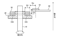
- FIG. 2 is a cross-sectional view showing the positional relationship between the magnet of the detection device and the sensor according to the first embodiment.
- FIG. 3 is a diagram illustrating an example of the relationship between the magnetic flux and the detection position in the first embodiment.
- FIG. 4 is a graph showing the relationship between the detection position and the detection accuracy in the first embodiment.
- FIG. 5 is a cross-sectional view showing an example of a magnet holder in a modified example.
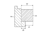
- FIG. 6 is an enlarged cross-sectional view showing an example of a magnet holder in a modified example.
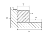
- FIG. 7 is an enlarged cross-sectional view showing an example of a magnet holder in another modified example.
- FIG. 1 is a front view showing an example of a detection device provided in a rotating body. As shown in FIG. 1, the detection device 1 is provided on the shaft 10.
- the shaft 10 is an example of a rotating body.
- the shaft 10 is inserted into the housing 90, for example.
- teeth 11, 12, and 13 are formed on the shaft 10.
- the shaft 10 is an input shaft that rotates via the teeth 11, 12, and 13 by receiving an external force from an external device such as a motor (not shown), human power, a load, or the like.
- FIG. 2 is a cross-sectional view showing the positional relationship between the magnet of the detection device and the sensor according to the first embodiment.
- the detection device 1 includes a magnet holder 20, a magnet 30, and a sensor 50. Further, the detection device 1 may further include a control unit (not shown).
- the detection device 1 shown in FIG. 2 is partially different from the detection device 1 shown in FIG. 1 in the position of the sensor 50 and the shape of the magnet holder 20.
- the magnet holder 20 is mounted on the outer side of the shaft 10 in the radial direction, for example.
- the magnet holder 20 is formed so as to surround the shaft 10 in the circumferential direction.
- the magnet holder 20 may be formed of, for example, a magnetic material having a magnetic shielding action.
- the magnet 30 is, for example, an annular magnet.
- the magnet 30 is fixed to the magnet holder 20 and arranged in the circumferential direction of the shaft 10.
- the magnet 30 rotates in conjunction with the rotation of the shaft 10.
- the magnet holder 20 may be used as a back yoke and is made of, for example, a soft magnetic material.
- the sensor 50 detects the magnetic flux of the magnet 30 that changes according to the rotation of the shaft 10, and outputs the detection result to a control unit (not shown).
- the sensor 50 is mounted on the substrate 40, for example.
- the sensor 50 is, for example, a Hall IC.
- the control unit detects at least one of the rotation speed and the rotation angle of the shaft 10 by using the detection result output from the sensor 50.
- the magnet holder 20, the magnet 30, and the sensor 50 included in the detection device 1 in the present embodiment are also mounted in the housing 90.
- the sensor 50 is installed, for example, on the upper surface of the substrate 40.
- wiring for connecting the sensor 50 and the control unit is formed on the substrate 40.
- the shaft 10 is equipped with a magnetic sensor 60 different from the sensor 50.
- the magnetic sensor 60 is arranged on the side opposite to the sensor 50 (lower side in FIG. 2) in the axial direction with the magnet holder 20 interposed therebetween.
- the magnetic sensor 60 includes a magnet different from the magnet 30, and detects the torque and the like of the shaft 10 using the magnet.
- the magnetic sensor 60 is, for example, a torque sensor, but may be a sensor that detects other states of the shaft 10 such as acceleration and position as long as it is a sensor that detects magnetism.
- the magnetic sensor 60 is an example of the second sensor.
- the detection accuracy of the magnetic sensor 60 deteriorates when it is affected by magnetic flux from the outside. Therefore, in the present embodiment, the magnetic flux generated from the magnet 30 is suppressed toward the magnetic sensor 60 side (negative direction side in the axial direction) due to the magnetic shielding action of the magnet holder 20. As a result, deterioration of the detection accuracy of the magnetic sensor 60 is suppressed. Further, the magnetic flux generated from a magnet or coil (not shown) detected by the magnetic sensor 60 or the magnetic flux generated from another magnet (not shown) provided inside the housing 90 interferes with the sensor 50, causing magnetic noise. Since it can be prevented from being generated, the sensor 50 can detect the magnetic flux of the magnet 30 more accurately.
- FIG. 3 is a diagram illustrating an example of the relationship between the magnetic flux and the detection position in the first embodiment.
- the magnet 30 has an N pole (3N) on one side in the radial direction and an S pole (3S) on the other side.
- N pole (3N) the left side on the drawing
- S pole (3S) the right side is described as an S pole (3S).
- the magnetic flux lines M1 to M5 constituting the magnetic flux M all go from the N pole (3N) to the S pole (3S). Further, as shown in FIG. 2, a magnet holder 20 which is a magnetic material is arranged below the magnet 30 on the drawing (negative direction in the axial direction). In the present embodiment, the magnetic field lines M1 to M5 pass through the upper side (positive direction side in the axial direction) of the magnet 30 on the drawing and head toward the S pole. The lines of magnetic force passing under the magnet 30 are guided by the magnet holder 20 which is a magnetic material. Therefore, it is possible to shield the lines of magnetic force toward the lower side on the drawing.
- the directions of the lines of magnetic force M1 to M5 differ depending on the position where the lines of magnetic force are detected. For example, at position A2, all the lines of magnetic force M1 to M5 are directed toward the upper right on the drawing. On the other hand, at the position A1, the magnetic field line M3 toward the upper left direction M3L on the drawing, the magnetic force line M4 toward the upward (positive direction in the axial direction) M4U on the drawing, and the magnetic force line M5 toward the upper right direction M5R on the drawing. Are mixed. That is, at such a position A1, there is a variation in the directions of the magnetic field lines M1 to M5 constituting the magnetic flux. In such a case, it is difficult to accurately detect the magnetic flux.
- the sensor 50 is generally arranged at the position A0.
- the sensor 50 is arranged at the position A0, it may not be possible to sufficiently secure the radial size of the magnet holder 20 used as the back yoke. In this case, the magnetic sensor 60 is easily affected by the magnetic flux. Therefore, the sensor 50 in the present embodiment is arranged at a position A2 offset upward from the central position of the magnet 30 in the axial direction (positive direction in the axial direction), that is, away from the magnetic sensor 60 in the axial direction.
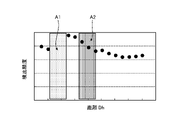
- FIG. 4 is a graph showing the relationship between the detection position and the detection accuracy in the first embodiment.
- the horizontal axis indicates the distance between the position where the sensor 50 is arranged and the magnet 30, and the vertical axis indicates the detection accuracy.
- the detection accuracy shown in FIG. 4 is shown, for example, by the correlation between the actual angle or rotation speed of the shaft 10 and the sensor information output by the sensor 50.
- the detection accuracy of the rotation speed and the angle based on the magnetic flux is extremely lowered as compared with the other detection positions. That is, the sensor 50 often outputs sensor information deviating from the actual angle and rotation speed.
- the senor 50 is arranged at a position A2 further separated from the position A1 in the upward direction (positive direction in the axial direction), for example. As shown in FIG. 4, at the position A2, it is suppressed that the detection accuracy by the sensor 50 is extremely lowered, so that erroneous detection of the angle and the rotation speed is suppressed.
- the detection accuracy is higher in the section between the position A1 and the position A2 than in the position A2.
- the position and measurement range of the sensor 50 may fluctuate due to an error such as an assembly tolerance of parts, vibration of a machine, or the like. Therefore, if the sensor 50 is to be provided in the section between the position A1 and the position A2, the measurement range may be included in the position A1. Considering this point, it is preferable that the sensor 50 is arranged at the position A2 which is not adjacent to the position A1.
- the position where the sensor 50 is installed is appropriately set according to the size of the magnet 30, the density of the magnetic flux generated from the magnet 30, the shape and size of the magnet holder 20, and the like.
- the radial distance Dw between the central portion of the sensor 50 and the outer peripheral end portion of the magnet 30 shown in FIG. 2 and the radial width D3 of the annular portion of the magnet 30 are, for example, 5.0 mm, respectively. Is set to.
- the distance Dh in the axial direction between the central portion in the axial direction of the sensor 50 shown in FIG. 2 and the central portion in the axial direction of the magnet 30 is, for example, 4.0 mm (width D3 in the radial direction of the annular portion of the magnet 30). 80%).
- the detection device 1 in the present embodiment measures at least one of the rotation speed and the rotation angle of the shaft 10 by using the detection result.
- the detection device 1 includes a magnet 30, a magnet holder 20, and a sensor 50.
- the magnet 30 rotates in conjunction with the shaft 10.
- the magnet holder 20 is located on one side (negative direction side in the axial direction) of the magnet 30 in the rotation axis direction.
- the sensor 50 is installed on the substrate 40, detects the magnetic flux of the magnet 30, and outputs the detection result.
- the substrate 40 is located on the other side (positive direction side in the axial direction) of the magnet 30 in the rotation axis direction and is separated from the magnet 30 in the rotation axis direction, and the sensor 50 is in the axial direction of the substrate 40. It is arranged on the other side (the positive side in the axial direction). According to such a configuration, it is possible to improve the detection accuracy of the rotation speed or the rotation angle of the shaft 10.
- the magnet holder 20 in this embodiment is made of, for example, a magnetic material.
- the magnet 30 is formed in an annular shape in the circumferential direction of the shaft 10. Further, on one side (negative direction side in the axial direction) of the magnet holder 20, a magnetic sensor 60 different from the sensor 50 is further provided. As a result, the magnetic flux from the magnet 30 toward the magnetic sensor 60 is shielded by the magnet holder 20, so that deterioration of the detection accuracy of the magnetic sensor 60 due to the influence of the magnetic flux can be suppressed. Further, since it is possible to prevent the magnetic flux generated from the magnetic flux generation source such as a magnet (not shown) detected by the magnetic sensor 60 from interfering with the sensor 50, the detection accuracy in which the sensor 50 detects the magnetic flux of the magnet 30 Can be improved.
- the shape and size of the magnet holder 20 are not limited to those shown in FIG. 2, and may be appropriately changed according to the dimensions of the device, the position of the magnetic sensor 60, and the like.
- the lower portion of the magnet holder 20 (the portion on the negative side in the axial direction) is larger in the radial direction than the magnet 30 in the configuration shown in FIG. 2, but is not limited to this, and as shown in FIG. 1, the magnet 30 May be smaller in the radial direction than.
- FIG. 5 is a cross-sectional view showing an example of a magnet holder in a modified example.
- the shaft 10 inserted through the magnet holder 20a and the magnetic sensor 60 mounted on the shaft 10 are not shown.
- the size D in the radial direction of the lower portion of the magnet holder 20a is smaller than the size D1 in the radial direction of the magnet.
- the magnetic sensor 60 detects a magnetic force at the measurement point K1, for example.
- the outer diameter of the magnet holder 20a that is, the size D in the radial direction of the lower portion of the magnet holder 20a is set to the condition shown in the following equation 1. It is preferable to meet.
- D2 in Equation 1 indicates the inner diameter of the magnet 30 shown in FIG. As shown in FIG. 5, D2 is substantially the same as the inner diameter of the magnet holder 20a, that is, the size of the upper portion of the magnet holder 20a in the radial direction.
- the outer diameter D of the magnet holder 20a is smaller than the outer diameter D1 of the magnet 30, if the condition shown in Equation 1 is satisfied, the influence of the magnetic flux of the magnet 30 on the measurement point K1 It can be suppressed from reaching.
- FIG. 6 is an enlarged cross-sectional view showing an example of a magnet holder in a modified example.
- FIG. 6 is an enlarged view of the portion shown in the frame F of FIG.
- FIG. 6 is an example of the magnet holder 20a satisfying the condition shown in the formula 1.
- the difference D5 between the outer diameter D of the magnet holder 20 and the inner diameter D2 of the magnet 30 and the difference D4 between the outer diameter D1 of the magnet 30 and the outer diameter D of the magnet holder 20 are magnets.
- the conditions shown in the following equations 2 and 3 are satisfied for the width D3 in the radial direction of the annular portion of 30.
- the magnetic shielding action by increasing the outer diameter D of the magnet holder 20 is particularly effective when the following conditions are satisfied.
- FIG. 7 is an enlarged cross-sectional view showing an example of a magnet holder in another modified example.
- An enlarged example of the portion shown in the frame F of FIG. 5 in the magnet holder 20b satisfying the condition shown in the formula 4 is shown.
- the difference D7 between the outer diameter D and the inner diameter D2 of the magnet holder 20 and the difference D6 between the outer diameter D1 of the magnet 30 and the outer diameter D of the magnet holder 20 are an annular shape of the magnet 30.
- the conditions shown in the following equations 5 and 6 are satisfied for the width D3 of the portion in the radial direction.
- the detection device 1 of the present embodiment when the outermost diameter of the magnet holder 20 is D, the outer diameter of the magnet 30 is D1, and the inner diameter of the magnet 30 is D2, (7D1 + 13D2) / 20 ⁇ Satisfy D. Further, D ⁇ 2D1-D2 may be further satisfied. According to such a configuration, the magnetic shielding action of the magnet holder 20 on the magnetic sensor 60 and the size of the magnet holder 20 can be adjusted in a well-balanced manner.
- the shaft 10 is an input shaft
- the present invention is not limited to this, and the shaft 10 may be an output shaft that transmits power to an external device via the teeth 11, 12, and 13.
- the control unit is arranged, for example, in the housing 90, but is not limited to this, and may be arranged in another device, for example, outside the housing 90, which can communicate with the sensor 50 by wire or wirelessly. good.
- the present invention is not limited to the above embodiments.
- the present invention also includes a configuration in which the above-mentioned components are appropriately combined. Further, further effects and modifications can be easily derived by those skilled in the art. Therefore, the broader aspect of the present invention is not limited to the above-described embodiment, and various modifications can be made.
- 1 detection device 10 shafts, 20 magnet holders, 30 magnets, 40 boards, 50 sensors, 60 magnetic sensors, 90 housings
Landscapes
- Physics & Mathematics (AREA)
- General Physics & Mathematics (AREA)
- Transmission And Conversion Of Sensor Element Output (AREA)
Abstract
検出装置(1)は、センサ情報を用いて、回転体(10)の回転数及び回転角度のうち、少なくともいずれかを測定する。検出装置は、マグネット(30)と、マグネットホルダ(20)と、センサ(50)とを備える。マグネットは、前記回転体と連動して回転する。マグネットホルダは、回転軸方向において、前記マグネットの一方側に位置する。センサは、基板(40)に設置され、前記マグネットの磁束を検出し、検出結果を前記センサ情報として出力する。前記基板は、前記回転軸方向において、前記マグネットの他方側に位置し、かつ、前記回転軸方向において、前記マグネットと離間しており、前記基板の前記軸方向他方側に配置される。
Description
本発明は、検出装置に関する。
シャフト等の回転体の回転数又は回転角度を測定するために、回転体に固定された磁石から発生する磁束を用いるセンサが知られている。
しかし、センサと磁石との位置関係によっては、磁石から発生する磁束を正確に測定できない場合がある。
一つの側面では、回転数又は回転角度の検出精度を向上させる検出装置を提供することを目的とする。
一つの態様において、検出装置は、センサ情報を用いて、回転体の回転数及び回転角度のうち、少なくともいずれかを測定する。検出装置は、マグネットと、マグネットホルダと、センサとを備える。マグネットは、前記回転体と連動して回転する。マグネットホルダは、回転軸方向において、前記マグネットの一方側に位置する。センサは、基板に設置され、前記マグネットの磁束を検出し、検出結果を前記センサ情報として出力する。前記基板は、前記回転軸方向において、前記マグネットの他方側に位置し、かつ、前記回転軸方向において、前記マグネットと離間しており、前記基板の前記軸方向他方側に配置される。
一つの態様によれば、回転数又は回転角度の検出精度を向上できる。
以下に、本願の開示する検出装置の実施形態を図面に基づいて詳細に説明する。なお、図面における各要素の寸法の関係、各要素の比率などは、現実と異なる場合がある。図面の相互間においても、互いの寸法の関係や比率が異なる部分が含まれている場合がある。各図面において、説明を分かりやすくするために、後に説明するシャフト10における軸方向、径方向及び周方向のうち、少なくともいずれかを含む座標系を図示する場合がある。また、以下において、シャフト10の回転軸方向を、単に「軸方向」と表記する場合がある。
図1は、回転体に備えられた検出装置の一例を示す正面図である。図1に示すように、検出装置1は、シャフト10に備えられる。なお、シャフト10は、回転体の一例である。
シャフト10は、例えば、ハウジング90に挿通される。シャフト10には、例えば歯11、12、13が形成される。シャフト10は、歯11、12、13を介して、図示しないモータ等の外部の装置や人力、荷重等から外力を受けて回転する入力軸となる。
本実施形態における検出装置1は、シャフト10の回転数及び回転角度のうち、少なくともいずれかを検出する。図2は、第1の実施形態における検出装置の磁石とセンサとの位置関係を示す断面図である。本実施形態において、検出装置1は、マグネットホルダ20と、マグネット30と、センサ50とを備える。また、検出装置1は、図示しない制御部をさらに備えてもよい。なお、図2に示す検出装置1は、図1に示す検出装置1とは、センサ50の位置やマグネットホルダ20の形状が一部異なる。
本実施形態において、マグネットホルダ20は、例えば、シャフト10の径方向における外側に装着される。マグネットホルダ20は、シャフト10を周方向に包囲するように形成される。マグネットホルダ20は、例えば、磁気シールド作用を備える磁性体で形成されてもよい。
マグネット30は、例えば、環状の磁石である。マグネット30は、マグネットホルダ20に固定されて、シャフト10の周方向に配置される。マグネット30は、シャフト10の回転に連動して回転する。マグネットホルダ20は、バックヨークとして用いられてもよく、例えば、軟質磁性材料で形成される。
センサ50は、シャフト10の回転に応じて変化するマグネット30の磁束を検出し、検出結果を図示しない制御部に出力する。本実施形態において、センサ50は、例えば、基板40に搭載される。センサ50は、例えば、ホールICである。
制御部は、センサ50から出力された検出結果を用いて、シャフト10の回転数及び回転角度のうち、少なくともいずれかを検出する。
本実施形態における検出装置1に含まれるマグネットホルダ20、マグネット30及びセンサ50も、ハウジング90内に装着される。センサ50は、例えば、基板40の上面に設置される。
本実施形態において、基板40には、例えば、センサ50と制御部とを接続する配線が形成される。
また、本実施形態において、シャフト10には、センサ50とは異なる磁気センサ60が装着される。磁気センサ60は、マグネットホルダ20を挟んで、軸方向において、センサ50とは反対側(図2における下側)に配置される。磁気センサ60は、マグネット30とは異なる磁石を備え、当該磁石を用いてシャフト10のトルク等を検出する。磁気センサ60は、例えばトルクセンサであるが、磁気を検出するセンサであれば、加速度や位置等のシャフト10のその他の状態を検出するセンサであってもよい。なお、磁気センサ60は、第2のセンサの一例である。
磁気センサ60は、外部から磁束の影響を受けると、検出精度が低下する。このため、本実施形態において、マグネット30から発生する磁束は、マグネットホルダ20の磁気シールド作用により、磁気センサ60側(軸方向の負方向側)に向かうことが抑制される。これにより、磁気センサ60の検出精度の低下が抑制される。さらに、磁気センサ60が検出する、図示しないマグネットやコイル等から発生する磁束や、ハウジング90内部に備えられるその他の図示しないマグネット等から発生する磁束が、センサ50に対して干渉し、磁気ノイズが発生することを防ぐことができるため、センサ50がマグネット30の磁束をより正確に検出することが可能になる。
次に、本実施形態におけるセンサ50と、マグネット30により発生する磁束との関係について説明する。磁束を構成する磁力線は、磁石のN極からS極へと向かうことが知られている。図3は、第1の実施形態における磁束と検出位置との関係の一例を説明する図である。図2及び図3に示されるように、マグネット30は、径方向における一方にN極(3N)を備え、他方にS極(3S)を備える。図2及び図3においては、便宜上、図面上の左側がN極(3N)、右側がS極(3S)として説明する。
図3に示すように、磁束Mを構成する磁力線M1乃至M5は、いずれもN極(3N)から、S極(3S)へと向かう。また、図2に示すように、図面上のマグネット30の下側(軸方向における負方向)には、磁性体であるマグネットホルダ20が配置されている。本実施形態において、磁力線M1乃至M5は、図面上のマグネット30の上側(軸方向における正方向側)を通って、S極に向かう。なお、マグネット30の下側を通る磁力線は、磁性体であるマグネットホルダ20によって誘導される。そのため、図面上の下側に向かう磁力線を遮蔽することができる。
磁力線M1乃至M5の方向は、磁力線が検出される位置に応じて異なる。例えば、位置A2においては、いずれの磁力線M1乃至M5も、図面上の右上方向へと向かっている。一方、位置A1においては、図面上の左上方向M3Lへ向かう磁力線M3と、図面上の上方向(軸方向の正方向)M4Uへ向かう磁力線M4と、図面上の右上方向M5Rへと向かう磁力線M5とが混在している。すなわち、かかる位置A1においては、磁束を構成する磁力線M1乃至M5の方向にバラツキがある。このような場合、磁束を正確に検出することが難しい。
なお、図2に示す位置A0、すなわちマグネット30の軸方向における中心位置と略一致する位置においては、磁力線の方向のバラツキが小さいため、センサ50を位置A0に配置することが一般的である。しかし、センサ50が位置A0に配置される場合、バックヨークとして用いられるマグネットホルダ20の径方向の大きさを十分確保できないことがある。この場合、磁気センサ60は磁束の影響を受けやすくなる。そこで、本実施形態におけるセンサ50は、マグネット30の軸方向における中心位置から上方向(軸方向の正方向)、すなわち軸方向において磁気センサ60から遠ざかるようにオフセットされた位置A2に配置される。
図4は、第1の実施形態における検出位置と検出精度との関係を示すグラフである。図4において、横軸はセンサ50が配置される位置とマグネット30との距離を示し、縦軸は検出精度を示す。図4に示す検出精度は、例えば、実際のシャフト10の角度又は回転数と、センサ50が出力するセンサ情報との相関関係により示される。図4に示すように、位置A1においては、磁束に基づく回転数や角度の検出精度が、他の検出位置と比べて極端に低下する。すなわち、センサ50が、実際の角度や回転数から乖離したセンサ情報を出力する場合が多くなる。
そこで、本実施形態においては、センサ50は、図2及び図3に示すように、例えば、位置A1からさらに上方向(軸方向の正方向)に離間した位置A2に配置される。図4に示すように、位置A2においては、センサ50による検出精度が極端に低下することが抑制されるので、角度や回転数の誤検出が抑制される。
なお、図4に示すグラフにおいては、位置A1と位置A2との間の区間では、位置A2よりも検出精度が高い。しかし、部品の組み上げ公差等の誤差や、機械の振動等により、センサ50の位置や計測範囲が変動する場合がある。このため、位置A1と位置A2との間の区間にセンサ50を設けようとすると、計測範囲が位置A1に含まれる可能性がある。この点を考慮すると、センサ50は、位置A1と隣接していない位置A2に配置されることが好ましい。
また、センサ50が設置される位置は、マグネット30のサイズや、マグネット30から発生する磁束の密度、マグネットホルダ20の形状やサイズ等に応じて適宜設定される。本実施形態において、図2に示すセンサ50の中心部とマグネット30の外周端部との径方向における距離Dwおよび、マグネット30の環状部分の径方向における幅D3は、例えば、それぞれ、5.0mmに設定される。また、図2に示すセンサ50の軸方向における中心部と、マグネット30の軸方向における中心部との軸方向における距離Dhは、例えば、4.0mm(マグネット30の環状部分の径方向における幅D3の80%)に設定される。
以上説明したように、本実施形態における検出装置1は、検出結果を用いて、シャフト10の回転数及び回転角度のうち、少なくともいずれかを測定する。検出装置1は、マグネット30と、マグネットホルダ20と、センサ50とを備える。マグネット30は、シャフト10と連動して回転する。マグネットホルダ20は、回転軸方向において、マグネット30の一方側(軸方向の負方向側)に位置する。センサ50は、基板40に設置され、マグネット30の磁束を検出し、検出結果を出力する。基板40は、回転軸方向において、マグネット30の他方側(軸方向の正方向側)に位置し、かつ、回転軸方向において、マグネット30と離間しており、センサ50は、基板40の軸方向他方側(軸方向の正方向側)に配置される。かかる構成によれば、シャフト10の回転数又は回転角度の検出精度を向上させることができる。
また、本実施形態におけるマグネットホルダ20は、例えば、磁性体で構成される。また、マグネット30は、シャフト10の周方向に環状に形成される。さらに、マグネットホルダ20の一方側(軸方向の負方向側)には、センサ50とは異なる磁気センサ60がさらに備えられる。これにより、マグネット30から磁気センサ60に向かう磁束がマグネットホルダ20によりシールドされるので、磁束の影響による磁気センサ60の検出精度の低下を抑制できる。さらに、磁気センサ60が検出する、図示しないマグネット等の磁束の発生源から発生する磁束がセンサ50に対して干渉することを防ぐことができるため、センサ50がマグネット30の磁束を検出する検出精度を向上させることができる。
以上、本発明の実施形態について説明したが、本発明は上記実施形態に限定されるものではなく、その趣旨を逸脱しない限りにおいて種々の変更が可能である。例えば、マグネットホルダ20の形状やサイズは図2に示すものに限られず、装置の寸法や、磁気センサ60の位置等に応じて適宜変更してもよい。例えば、マグネットホルダ20の下部(軸方向の負方向側の部分)は、図2に示す構成においてはマグネット30よりも径方向において大きいが、これに限られず、図1に示すように、マグネット30よりも径方向において小さくてもよい。
バックヨークとなるマグネットホルダ20の磁気シールド作用は、マグネットホルダ20の径方向におけるサイズが大きいほど強くなることが知られている。しかし、ハウジング90内の限られた空間においては、マグネットホルダ20のサイズはできるだけ小さくすることが望ましい。以下、マグネットホルダ20の変形例として、マグネットホルダ20a及び20bについて説明する。図5は、変形例におけるマグネットホルダの一例を示す断面図である。なお、図5においては、マグネットホルダ20aに挿通されるシャフト10、及びシャフト10に装着される磁気センサ60の図示を省略している。図5においては、図1と同様に、マグネットホルダ20aの下部の径方向におけるサイズDは、マグネットの径方向のサイズD1よりも小さい。
図5において、磁気センサ60は、例えば、測定点K1において磁力を検出する。その場合において、磁気センサ60に対するマグネット30の磁束の影響を抑制するためには、マグネットホルダ20aの外径、すなわちマグネットホルダ20aの下部の径方向におけるサイズDは、以下の式1に示す条件を満たすことが好ましい。
(7D1+13D2)/20<D・・・(式1)
式1におけるD2は、図5に示すマグネット30の内径を示す。なお、図5に示すように、D2は、マグネットホルダ20aの内径、すなわちマグネットホルダ20aの上部の径方向におけるサイズと略同一である。本変形例において、マグネットホルダ20aの外径Dが、マグネット30の外径D1よりも小さい場合においても、式1に示す条件を満たす場合は、測定点K1に対してマグネット30の磁束の影響が及ぶことを抑制できる。
図6は、変形例におけるマグネットホルダの一例を示す拡大断面図である。図6は、図5の枠Fに示す部分を拡大した図である。図6は、式1に示す条件を満たすマグネットホルダ20aの一例である。図6に示すマグネットホルダ20aにおいて、マグネットホルダ20の外径Dとマグネット30の内径D2との差分D5と、マグネット30の外径D1とマグネットホルダ20の外径Dとの差分D4とは、マグネット30の環状部分の径方向における幅D3に対して、以下の式2及び式3に示す条件を満たす。
0.35D3<D5・・・(式2)
D4<0.65D3・・・(式3)
D4<0.65D3・・・(式3)
一方、マグネットホルダ20の外径Dを大きくすることによる磁気シールド作用は、以下の条件を満たす場合において特に有効である。
D<2D1-D2・・・(式4)
図7は、別の変形例におけるマグネットホルダの一例を示す拡大断面図である。式4に示す条件を満たすマグネットホルダ20bにおける、図5の枠Fに示す部分を拡大した一例を示す。図7に示すマグネットホルダ20bにおいて、マグネットホルダ20の外径Dと内径D2との差分D7と、マグネット30の外径D1とマグネットホルダ20の外径Dとの差分D6とは、マグネット30の環状部分の径方向における幅D3に対して、以下の式5及び式6に示す条件を満たす。
D6<D3・・・(式5)
D7<2D3・・・(式6)
D7<2D3・・・(式6)
なお、上記の式5及び式6を満たさない場合は、マグネットホルダ20bの磁気シールド作用の向上は、式5及び式6を満たす場合と比べると小さくなる。
以上説明したように、本実施形態における検出装置1において、マグネットホルダ20の最外径をD、マグネット30の外径をD1、マグネット30の内径をD2としたときに、(7D1+13D2)/20<Dを満たす。また、D<2D1-D2をさらに満たしてもよい。かかる構成によれば、マグネットホルダ20による磁気センサ60に対する磁気シールド作用と、マグネットホルダ20とのサイズとをバランスよく調整できる。
また、シャフト10が入力軸である例について説明したが、これに限られず、シャフト10が、歯11、12、13を介して、外部の装置に動力を伝達する出力軸であってもよい。
なお、制御部は、例えば、ハウジング90内に配置されるが、これに限られず、例えばハウジング90の外部にある、センサ50と有線又は無線による通信が可能な別の装置に配置されていてもよい。
また、上記実施の形態により本発明が限定されるものではない。上述した各構成要素を適宜組み合わせて構成したものも本発明に含まれる。また、さらなる効果や変形例は、当業者によって容易に導き出すことができる。よって、本発明のより広範な態様は、上記の実施の形態に限定されるものではなく、様々な変更が可能である。
1 検出装置、 10 シャフト、 20 マグネットホルダ、 30 マグネット、 40 基板、 50 センサ、 60 磁気センサ、 90 ハウジング
Claims (5)
- 回転体の回転数及び回転角度のうち、少なくともいずれかを検出する検出装置であって、
前記回転体と連動して回転するマグネットと、
回転軸方向において、前記マグネットの一方側に位置するマグネットホルダと、
基板に設置され、前記マグネットの磁束を検出するセンサと、
を備え、
前記基板は、前記回転軸方向において、前記マグネットの他方側に位置し、かつ、前記回転軸方向において、前記マグネットと離間しており、
前記センサは、前記基板の前記軸方向他方側に配置される、検出装置。 - 前記マグネットホルダは、磁性体で構成される、請求項1に記載の検出装置。
- 前記マグネットホルダの最外径をD、前記マグネットの外径をD1、前記マグネットの内径をD2としたときに、(7D1+13D2)/20<Dを満たす、請求項1又は2に記載の検出装置。
- D<2D1-D2をさらに満たす、請求項3に記載の検出装置。
- 前記マグネットは前記回転体の周方向に環状に形成され、
前記マグネットホルダの前記一方側に、前記センサとは異なる第2のセンサをさらに備える、請求項1乃至4のいずれか1つに記載の検出装置。
Applications Claiming Priority (2)
| Application Number | Priority Date | Filing Date | Title |
|---|---|---|---|
| JP2020-177934 | 2020-10-23 | ||
| JP2020177934A JP2022069019A (ja) | 2020-10-23 | 2020-10-23 | 検出装置 |
Publications (1)
| Publication Number | Publication Date |
|---|---|
| WO2022085779A1 true WO2022085779A1 (ja) | 2022-04-28 |
Family
ID=81290527
Family Applications (1)
| Application Number | Title | Priority Date | Filing Date |
|---|---|---|---|
| PCT/JP2021/039037 Ceased WO2022085779A1 (ja) | 2020-10-23 | 2021-10-22 | 検出装置 |
Country Status (3)
| Country | Link |
|---|---|
| JP (1) | JP2022069019A (ja) |
| TW (1) | TW202218298A (ja) |
| WO (1) | WO2022085779A1 (ja) |
Citations (4)
| Publication number | Priority date | Publication date | Assignee | Title |
|---|---|---|---|---|
| JPH09308171A (ja) * | 1996-05-13 | 1997-11-28 | Sankyo Seiki Mfg Co Ltd | 磁気式エンコーダ付きモータ |
| JP2011047765A (ja) * | 2009-08-26 | 2011-03-10 | Nikon Corp | エンコーダ |
| JP2018072086A (ja) * | 2016-10-26 | 2018-05-10 | 日立オートモティブシステムズ株式会社 | 回転角検出装置 |
| US20200191616A1 (en) * | 2018-12-12 | 2020-06-18 | Mando Corporation | Actuator assembly having rotary sensor responsive to rotation of magnet |
Family Cites Families (3)
| Publication number | Priority date | Publication date | Assignee | Title |
|---|---|---|---|---|
| US20050151534A1 (en) * | 2004-01-08 | 2005-07-14 | Omekanda Avoki M. | System and method for sensing angular position using ring magnet with sensor in flux return path |
| JP5886269B2 (ja) * | 2013-12-27 | 2016-03-16 | マブチモーター株式会社 | 回転検出装置およびモータ |
| JP7056602B2 (ja) * | 2018-03-20 | 2022-04-19 | 株式会社デンソー | 検出装置、制御装置、および、これを用いた電動パワーステアリング装置 |
-
2020
- 2020-10-23 JP JP2020177934A patent/JP2022069019A/ja active Pending
-
2021
- 2021-10-22 WO PCT/JP2021/039037 patent/WO2022085779A1/ja not_active Ceased
- 2021-10-22 TW TW110139211A patent/TW202218298A/zh unknown
Patent Citations (4)
| Publication number | Priority date | Publication date | Assignee | Title |
|---|---|---|---|---|
| JPH09308171A (ja) * | 1996-05-13 | 1997-11-28 | Sankyo Seiki Mfg Co Ltd | 磁気式エンコーダ付きモータ |
| JP2011047765A (ja) * | 2009-08-26 | 2011-03-10 | Nikon Corp | エンコーダ |
| JP2018072086A (ja) * | 2016-10-26 | 2018-05-10 | 日立オートモティブシステムズ株式会社 | 回転角検出装置 |
| US20200191616A1 (en) * | 2018-12-12 | 2020-06-18 | Mando Corporation | Actuator assembly having rotary sensor responsive to rotation of magnet |
Also Published As
| Publication number | Publication date |
|---|---|
| TW202218298A (zh) | 2022-05-01 |
| JP2022069019A (ja) | 2022-05-11 |
Similar Documents
| Publication | Publication Date | Title |
|---|---|---|
| JP4258376B2 (ja) | 多回転式エンコーダ | |
| JP6613895B2 (ja) | エンコーダ用スケール、エンコーダ、駆動装置及びステージ装置 | |
| US10591031B2 (en) | Electric actuator | |
| JP6385672B2 (ja) | モータ | |
| US10975984B2 (en) | Electrically operated valve | |
| CN107150759B (zh) | 用于电动自行车的轴集成角度感测设备和包括这种设备的电动自行车 | |
| TW201826670A (zh) | 馬達 | |
| US11408485B2 (en) | Electric actuator | |
| US11913784B2 (en) | Reduction mechanism and absolute encoder | |
| JP4269642B2 (ja) | モータ用センサ付き転がり軸受 | |
| CN107152937A (zh) | 轴集成角度感测设备 | |
| US11561117B2 (en) | Absolute encoder for detecting rotation angle | |
| US20220155051A1 (en) | Absolute encoder | |
| JP5082473B2 (ja) | ロータリエンコーダ | |
| EP4321842A1 (en) | Absolute encoder | |
| JP5041401B2 (ja) | 回転センサ | |
| WO2022085779A1 (ja) | 検出装置 | |
| US20250189294A1 (en) | Absolute encoder | |
| US12044551B2 (en) | Absolute encoder | |
| US11852511B2 (en) | Absolute encoder | |
| US12504306B2 (en) | Absolute encoder | |
| JP7404047B2 (ja) | 回転角度検出装置 | |
| JP2021056078A (ja) | 回転角度検出装置 | |
| TWI917599B (zh) | 絕對編碼器 | |
| JP4325381B2 (ja) | モータ用センサ付き転がり軸受 |
Legal Events
| Date | Code | Title | Description |
|---|---|---|---|
| 121 | Ep: the epo has been informed by wipo that ep was designated in this application |
Ref document number: 21882918 Country of ref document: EP Kind code of ref document: A1 |
|
| NENP | Non-entry into the national phase |
Ref country code: DE |
|
| 122 | Ep: pct application non-entry in european phase |
Ref document number: 21882918 Country of ref document: EP Kind code of ref document: A1 |