WO2022085514A1 - 制御装置、ロボット装置、ロボット装置の制御方法およびプログラム - Google Patents
制御装置、ロボット装置、ロボット装置の制御方法およびプログラム Download PDFInfo
- Publication number
- WO2022085514A1 WO2022085514A1 PCT/JP2021/037697 JP2021037697W WO2022085514A1 WO 2022085514 A1 WO2022085514 A1 WO 2022085514A1 JP 2021037697 W JP2021037697 W JP 2021037697W WO 2022085514 A1 WO2022085514 A1 WO 2022085514A1
- Authority
- WO
- WIPO (PCT)
- Prior art keywords
- hand
- flexible thin
- thin body
- cloth
- control device
- Prior art date
- Legal status (The legal status is an assumption and is not a legal conclusion. Google has not performed a legal analysis and makes no representation as to the accuracy of the status listed.)
- Ceased
Links
Images








Classifications
-
- B—PERFORMING OPERATIONS; TRANSPORTING
- B25—HAND TOOLS; PORTABLE POWER-DRIVEN TOOLS; MANIPULATORS
- B25J—MANIPULATORS; CHAMBERS PROVIDED WITH MANIPULATION DEVICES
- B25J13/00—Controls for manipulators
- B25J13/08—Controls for manipulators by means of sensing devices, e.g. viewing or touching devices
- B25J13/081—Touching devices, e.g. pressure-sensitive
- B25J13/082—Grasping-force detectors
-
- B—PERFORMING OPERATIONS; TRANSPORTING
- B25—HAND TOOLS; PORTABLE POWER-DRIVEN TOOLS; MANIPULATORS
- B25J—MANIPULATORS; CHAMBERS PROVIDED WITH MANIPULATION DEVICES
- B25J13/00—Controls for manipulators
- B25J13/08—Controls for manipulators by means of sensing devices, e.g. viewing or touching devices
- B25J13/081—Touching devices, e.g. pressure-sensitive
- B25J13/084—Tactile sensors
-
- B—PERFORMING OPERATIONS; TRANSPORTING
- B25—HAND TOOLS; PORTABLE POWER-DRIVEN TOOLS; MANIPULATORS
- B25J—MANIPULATORS; CHAMBERS PROVIDED WITH MANIPULATION DEVICES
- B25J15/00—Gripping heads and other end effectors
- B25J15/08—Gripping heads and other end effectors having finger members
-
- B—PERFORMING OPERATIONS; TRANSPORTING
- B25—HAND TOOLS; PORTABLE POWER-DRIVEN TOOLS; MANIPULATORS
- B25J—MANIPULATORS; CHAMBERS PROVIDED WITH MANIPULATION DEVICES
- B25J9/00—Program-controlled manipulators
- B25J9/0084—Program-controlled manipulators comprising a plurality of manipulators
- B25J9/0087—Dual arms
-
- B—PERFORMING OPERATIONS; TRANSPORTING
- B25—HAND TOOLS; PORTABLE POWER-DRIVEN TOOLS; MANIPULATORS
- B25J—MANIPULATORS; CHAMBERS PROVIDED WITH MANIPULATION DEVICES
- B25J9/00—Program-controlled manipulators
- B25J9/16—Program controls
- B25J9/1612—Program controls characterised by the hand, wrist, grip control
-
- B—PERFORMING OPERATIONS; TRANSPORTING
- B25—HAND TOOLS; PORTABLE POWER-DRIVEN TOOLS; MANIPULATORS
- B25J—MANIPULATORS; CHAMBERS PROVIDED WITH MANIPULATION DEVICES
- B25J9/00—Program-controlled manipulators
- B25J9/16—Program controls
- B25J9/1679—Program controls characterised by the tasks executed
- B25J9/1682—Dual arm manipulator; Coordination of several manipulators
-
- G—PHYSICS
- G05—CONTROLLING; REGULATING
- G05B—CONTROL OR REGULATING SYSTEMS IN GENERAL; FUNCTIONAL ELEMENTS OF SUCH SYSTEMS; MONITORING OR TESTING ARRANGEMENTS FOR SUCH SYSTEMS OR ELEMENTS
- G05B2219/00—Program-control systems
- G05B2219/30—Nc systems
- G05B2219/39—Robotics, robotics to robotics hand
- G05B2219/39123—Manipulate, handle flexible object
-
- G—PHYSICS
- G05—CONTROLLING; REGULATING
- G05B—CONTROL OR REGULATING SYSTEMS IN GENERAL; FUNCTIONAL ELEMENTS OF SUCH SYSTEMS; MONITORING OR TESTING ARRANGEMENTS FOR SUCH SYSTEMS OR ELEMENTS
- G05B2219/00—Program-control systems
- G05B2219/30—Nc systems
- G05B2219/39—Robotics, robotics to robotics hand
- G05B2219/39505—Control of gripping, grasping, contacting force, force distribution
-
- G—PHYSICS
- G05—CONTROLLING; REGULATING
- G05B—CONTROL OR REGULATING SYSTEMS IN GENERAL; FUNCTIONAL ELEMENTS OF SUCH SYSTEMS; MONITORING OR TESTING ARRANGEMENTS FOR SUCH SYSTEMS OR ELEMENTS
- G05B2219/00—Program-control systems
- G05B2219/30—Nc systems
- G05B2219/39—Robotics, robotics to robotics hand
- G05B2219/39533—Measure grasping posture and pressure distribution
Definitions
- This technique relates to a control device for a robot that handles a flexible thin body such as cloth, a robot device equipped with the control device, a control method thereof, and a program.
- a straight line portion is detected from a contour image of a fabric, the detected straight line portion is determined to be the edge portion of the cloth, and the determined edge portion of the cloth is formed by a plurality of finger portions.
- a deploying device to grip is disclosed.
- an object of the present technology is to provide a control device, a robot device, a control method and a program of the robot device capable of detecting and gripping the end portion of the undeveloped cloth.
- the control device includes an acquisition unit, an operation command generation unit, and a determination unit.
- the acquisition unit acquires the output of the first pressure distribution sensor arranged on the grip surface of the first hand and the output of the second pressure distribution sensor arranged on the grip surface of the second hand.
- the operation command generation unit has a first grip command for causing the second hand to grip the first predetermined portion of the flexible thin body gripped by the first hand, and the flexibility by the second hand. While maintaining the gripping operation of the thin body, a first movement command for moving the second hand relative to the flexible thin body in a predetermined direction from the first predetermined portion is generated.
- the determination unit determines whether or not the second hand has reached the end of the flexible thin body based on the output of the second pressure distribution sensor.
- the second hand is flexible based on the change in the output of the second pressure distribution sensor when the second hand gripping the flexible thin body is moved relative to the flexible thin body. It is configured to determine if it has reached the end of the thin body. This makes it possible to detect and grip the end portion of the flexible thin body even when the flexible thin body is placed randomly.
- the operation command generation unit further issues a second grip command for causing the first hand to grip a second predetermined portion near or near the end of the flexible thin body gripped by the second hand. May be generated. Based on the output of the first pressure distribution sensor, the determination unit further determines whether or not the second predetermined portion is the end portion of the flexible thin body.
- the first hand is different from the one end of the flexible thin body in a state where the second hand grips one end of the flexible thin body. It may be configured to repeatedly generate the second grip command until the end of the grip is gripped.
- the operation command generation unit While maintaining the gripping operation of the flexible thin body by the first hand, directs the first hand toward the corners of the flexible thin body and turns the flexible thin body into the flexible thin body. A second movement command for relative movement may be further generated.
- the operation command generation unit holds one corner of the movable thin body by the first hand, and maintains the gripping operation of the flexible thin body by the second hand.
- a third movement command may be further generated to move the second hand relative to the flexible thin body toward the other corners of the flexible thin body.
- the predetermined direction may be the direction of gravity. Thereby, the lower end portion of the flexible thin body suspended from the first end portion can be detected.
- the acquisition unit may be configured to further acquire information regarding the facing distance between the gripping surfaces of the second hand that grips the first predetermined portion.
- the determination unit determines whether or not the first predetermined portion held by the second hand is the thickness of one flexible thin body based on the information regarding the facing distance. judge.
- the determination unit Based on the pressure distribution detected by the second pressure distribution sensor, the determination unit has a first region in which the pressure magnitude is equal to or greater than a predetermined value and a second region in which the pressure magnitude is less than the predetermined value. It may be configured to determine that the second hand has reached the end of the flexible thin body when it is determined that the interface with and is extended along at least any uniaxial direction.
- the determination unit determines that the boundary between the first region and the second region extends along a biaxial direction in which they intersect each other, the second hand is flexible. It may be configured to determine that it has reached the corner of the thin body.
- the determination unit has a first region where the pressure magnitude is equal to or greater than a predetermined value and a second region where the pressure magnitude is less than the predetermined value, based on the pressure distribution detected by the first pressure distribution sensor. Even if it is configured to determine that the second predetermined portion is the end portion of the flexible thin body when it is determined that the boundary portion with the region of the above extends along at least an arbitrary uniaxial direction. good.
- the acquisition unit may further acquire information regarding the weight of the flexible thin body gripped by the first hand.
- the determination unit determines whether or not the weight of the flexible thin body held by the first hand is the weight of one flexible thin body based on the information regarding the weight. To judge.
- the operation command generation unit may be configured to further generate a folding command in which the corner portions of the flexible thin body are overlapped with each other.
- the folding command superimposes the first corner portion gripped by the first hand on the second corner portion facing the first corner portion in the direction of gravity, and is gripped by the second hand.
- the third corner portion may be configured to perform an operation of superimposing the third corner portion on the fourth corner portion facing the third corner portion in the direction of gravity.
- the robot device includes a first hand, a second hand, and a control circuit.
- the first hand has a first pressure distribution sensor arranged on the gripping surface.
- the second hand has a second pressure distribution sensor disposed on the gripping surface.
- the control circuit has an acquisition unit, an operation command generation unit, and a determination unit.
- the acquisition unit acquires the output of the first pressure distribution sensor and the output of the second pressure distribution sensor.
- the operation command determination unit has a first grip command for causing the second hand to grip the first predetermined portion of the flexible thin body gripped by the first hand, and the flexibility by the second hand.
- a first movement command for moving the second hand relative to the flexible thin body in a predetermined direction from the first predetermined portion is generated.
- the determination unit determines whether or not the second hand has reached the end of the flexible thin body based on the output of the second pressure distribution sensor.
- the second hand grips the first predetermined portion of the flexible thin body gripped by the first hand. While maintaining the gripping operation of the flexible thin body by the second hand, the second hand is moved relative to the flexible thin body in a predetermined direction from the first predetermined portion. Based on the output of the pressure distribution sensor arranged on the gripping surface of the second hand, it is determined whether or not the second hand has reached the end of the flexible thin body.
- the program related to one form of this technique is applied to the control device of the robot device.
- a step of causing the second hand to grip the first predetermined portion of the flexible thin body gripped by the first hand A step of moving the second hand relative to the flexible thin body in a predetermined direction from the first predetermined portion while maintaining the gripping operation of the flexible thin body by the second hand.
- the step of determining whether or not the second hand has reached the end of the flexible thin body is executed.
- FIG. 1 is a schematic configuration diagram of a robot device according to an embodiment of the present technology.
- the robot device 10 of the present embodiment includes a first arm 21 having a first hand 11 and a second arm 22 having a second hand 12.
- the first arm 21 and the second arm 22 are articulated arms, and are configured to be able to move the first hand 11 and the second hand 12 to any position in any posture.
- the first arm 21 and the second arm 22 are commonly supported by the drive unit 30.
- the drive unit 30 includes various actuators and drive circuits (electrical circuit and fluid pressure circuit) that drive each unit of the first and second hands 11, 12 and the first and second arms 21 and 22.
- the drive unit 30 controls the drive of each unit based on an operation command output from the control circuit 50 described later.
- the drive unit 30 is installed at a predetermined height position on the workbench 1 via the base 31, and is rotatably configured around the base 31.
- the robot device 10 takes out the cloth C, which is an object to be handled, from the accommodating portion 2 placed on the side of the base 31, unfolds the taken out cloth C by the procedure described later, and folds the cloth C on the workbench 1. To execute.
- a plurality of cloths C are stacked in the accommodating portion 2.
- the accommodation form of each cloth C is not particularly limited, and may be randomly stacked.
- Cloth C is, for example, a flexible or deformable thin object (hereinafter, also referred to as a flexible thin body) such as a towel or sheets.
- a flexible thin body such as a towel or sheets.
- the shape of the cloth C is typically a rectangle, but may be another shape, and is not limited to shaping, and may be a shirt or the like.
- the flexible thin body may be made of other materials such as a vinyl sheet in addition to the cloth.
- FIG. 2 is a side view showing details of the first hand 11 and the second hand 12.
- the first hand 11 and the second hand 12 each have the same configuration, and the reference numerals in parentheses in the figure indicate the components related to the second hand 12.
- the first hand 11 has a first finger unit 110.
- the first finger unit 110 is composed of a two-finger gripper having two finger portions 111 and 112 facing each other.
- Each finger portion 111, 112 has an articulated structure having a rotation axis P, and the tip portions of the finger portions 111, 112 can be moved in a direction of approaching or separating from each other in a state of being parallel to each other.
- the inner surface side of each finger portion 111, 112 is formed as a gripping surface capable of gripping a handling object (cloth C), and a first pressure distribution sensor 41 is arranged on each of these gripping surfaces.
- the second hand 12 has a second finger unit 120.
- the second finger unit 120 is composed of a two-finger gripper having two finger portions 121 and 122 facing each other.
- Each finger portion 121, 122 has an articulated structure having a rotation axis P, and the tip portions of the finger portions 121, 122 can be moved in a direction of approaching or separating from each other in a state parallel to each other.
- the inner surface side of each finger portion 121, 122 is formed as a gripping surface capable of gripping a handling object (cloth C), and a second pressure distribution sensor 42 is arranged on each of these gripping surfaces.
- the first pressure distribution sensor 41 and the second pressure distribution sensor 42 have a detection surface S (see FIG. 3) parallel to the gripping surface, and detect the in-plane distribution of the pressure acting on the detection surface S.
- the first pressure distribution sensor 41 may be arranged in only one of the two finger portions 111 and 112.
- the second pressure distribution sensor 42 may be arranged in only one of the two finger portions 121 and 122.
- the first and second pressure distribution sensors 41 and 42 have the same configuration as each other, and are composed of, for example, a capacitance type pressure sensor as shown in FIG.
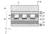
- FIG. 3 is a schematic side sectional view showing a configuration example of the first and second pressure distribution sensors 41 and 42. As shown in the figure, the first and second pressure distribution sensors 41 and 42 have the clearance layer 25 and the sensor unit 26 in order from the upper side (outside) in the stacking direction (z-axis direction) perpendicular to the gripping surface. I have.
- the first electrode film layer 35, the deformed layer 37, the sensor electrode layer 27, the fixed layer 45, and the second electrode film layer 36 are laminated in order from above (outside) in the stacking direction (z-axis direction). It is composed of.
- the sensor electrode layer 27 is flexible and has a base material 28 and a plurality of sensing units 29 arranged in a matrix in the plane of the base material 28.
- the sensing unit 29 is a capacitance type sensor, and is regularly arranged at predetermined intervals in the width direction (x direction) and the length direction (y direction) in the sensor electrode layer 27.
- Each sensing unit 29 includes, for example, a comb-shaped pulse electrode (not shown) and a comb-shaped sensor electrode.
- the first electrode film layer 35 and the second electrode film layer 36 are arranged at positions sandwiching the sensor electrode layer 27 in the stacking direction (z-axis direction).
- the first electrode film layer 35 has flexibility, and is configured by laminating the first film layer 35b and the first reference electrode layer 35a.
- the second electrode film layer 36 also has flexibility, and is configured by laminating the second film layer 36b and the second reference electrode layer 36a.
- the first reference electrode layer 35a and the second reference electrode layer 36a are ground electrodes and are connected to the ground potential.
- the fixed layer 45 is interposed between the sensor electrode layer 27 and the second electrode film layer 36.
- the fixed layer 45 adjusts the distance (gap) between the sensor electrode layer 27 and the second reference electrode layer 36a in the stacking direction (z-axis direction).
- the deformable layer 37 is interposed between the sensor electrode layer 27 and the first electrode film layer 35.
- the deformable layer 37 is configured to be elastically deformable in response to an external force by the user.
- the deformable layer 37 has a patterning structure and a hollow portion 39 in which the patterning structure does not exist.
- the patterning structure is composed of a plurality of pillar portions 38 arranged apart from each other in the horizontal direction (xy direction) in each layer, and the hollow portion 39 is a portion where the pillar portion 38 does not exist.
- the plurality of pillar portions 38 in the deformable layer 37 are arranged at positions in the sensor electrode layer 27 that do not correspond to the sensing portion 29 in the stacking direction (z-axis direction).
- the clearance layer 25 is arranged outside the sensor unit 26 so as to face the first electrode film layer 35.
- the clearance layer 25 is laminated on the sensor portion 26 via an adhesive layer.
- the clearance layer 25 forms the gripping surfaces of the first and second hands 11 and 12.
- the clearance layer 25 is made of a locally elastically deformable material such as a resin sheet, a rubber sheet, or leather.
- the first and second pressure distribution sensors 41 and 42 are attached to the finger portions 111, 112, 121 and 122 on the side of the second electrode film layer 36.
- the surface of the clearance layer 25 is the detection surface S constituting the gripping surface.
- the first and second pressure distribution sensors 41 and 42 configured as described above, when an external force is applied to the detection surface S, the clearance layer 25 is deformed and the first electrode film layer 35 directly below is the sensor electrode. It is pushed to the layer 27 side. When the first electrode film layer 35 is pushed in, the deformed layer 37 is elastically deformed, whereby the first reference electrode layer 35a (ground potential) approaches the sensing portion 29 in the sensor electrode layer 27. At this time, since the capacitance between the pulse electrode and the sense electrode changes in the sensing unit 29, the first and second pressure distribution sensors 41 and 42 apply a pressing force according to the amount of change in the capacitance. To detect. As a result, the pressure distribution can be detected from the coordinates of the sensing unit 29.
- the first and second pressure distribution sensors 41 and 42 may be configured to be able to detect not only the pressure distribution on the detection surface S but also the shear force acting on the detection surface S and its distribution.
- the robot device 10 further includes a control circuit 50 (control device) that controls the operation of each part of the first and second hands 11, 12, the first and second arms 21, 22 and the like.
- the control circuit 50 may be arranged inside the drive unit 30, or may be configured as a unit separate from the drive unit 30.
- FIG. 4 is a block diagram showing the configuration of the control circuit 50.
- the control circuit 50 is composed of a computer including a CPU (Central Processing Unit) and a memory, and executes various functions described later by executing a program stored in the memory.
- the control circuit 50 has an acquisition unit 51, an operation command generation unit 52, and a determination unit 53 as its functional blocks.
- the acquisition unit 51 acquires the output of the first pressure distribution sensor 41 and the output of the second pressure distribution sensor 42.
- the acquisition unit 51 is further configured to be able to acquire the outputs of various sensors that detect the posture, position, operating state, etc. of the first hand 11, the second hand 12, the first arm 21, and the second arm 22 of the robot device 10. Will be done.
- the control circuit 50 detects the positions and postures of the first hand 11 and the second hand 12 based on the outputs of these various sensors. Examples of the various sensors include an angle sensor, an angular velocity sensor, a torque sensor, a force / moment sensor, a current sensor, a temperature sensor, and a camera.
- the acquisition unit 51 Based on the outputs of the first and second pressure distribution sensors 41 and 42, the acquisition unit 51 has a gripping force on the cloth C gripped by the finger units 110 and 120 of the first and second hands 11 and 12, and its in-plane distribution. Etc. are detected. The acquisition unit 51 detects the position of the cloth gripped by the first and second hands 11 and 12 based on the outputs of the first and second pressure distribution sensors 41 and 42.
- the acquisition unit 51 further determines the weight and thickness of the cloth C gripped by the first hand 11 or the second hand 12, the relative position between the first hand 11 and the second hand 12, based on the outputs of the various sensors.
- Each information related to the facing distance between the gripping surfaces of the first hand 11 and the second hand 12 is acquired.
- the operation command generation unit 52 drives the first and second hands 11, 12 and the first and second arms 21 and 22 based on the outputs of the first and second pressure distribution sensors 41 and 42 and the various sensors. Generate an operation command.
- the operation command generation unit includes a grip command for the cloth C for the first and second hands 11 and 12, a movement command for the cloth C for the first and second hands 11 and 12, and the like.
- the grip command of the cloth C includes a strong grip command (hereinafter, also referred to as a strong grip command) for holding the grip position with respect to the cloth C, and a grip force capable of relative movement (sliding operation) with respect to the cloth C to grip the cloth C. It includes a weak grip command (hereinafter, also referred to as a weak grip command) and a grip release command for releasing the grip operation on the cloth C.
- the operation command generation unit 52 controls the drive of the first and second hands 11 and 12 by a procedure as described later, and the operation command for unfolding and folding the cloth C taken out from the accommodating unit 2. To generate.
- the operation command generation unit 52 has a function of planning each operation of the gripping operation, the unfolding operation, and the folding operation of the cloth C, and controlling those operations.
- the determination unit 53 determines whether the gripping position of the cloth C by the first and second hands 11 and 12 is at the end of the cloth C based on the outputs of the first and second pressure distribution sensors 41 and 42. It is configured to determine whether or not. Further, the determination unit 53 determines whether or not the thickness of the cloth C gripped by the first and second hands 11 and 12 corresponds to the thickness of one cloth, and further, the first and second hands 11 and 12. It is configured to determine whether or not the weight of the cloth C gripped by the cloth C corresponds to the weight of one piece of cloth.
- the end portion of the cloth C is the edge corresponding to each side of the cloth C or any one of the four corners of the cloth C in the present embodiment in which the cloth C has a rectangular shape. Means the corner.
- the edges or corners of the cloth C are collectively referred to as the ends of the cloth C.
- the control circuit 50 further has a storage unit 54.
- the storage unit 54 is composed of a ROM (Read Only Memory) or a RAM (Random Access Memory), and stores programs, control parameters, and the like for causing the robot device 10 to execute various operations described later.
- the storage unit 54 further stores the size and shape of the cloth C, the thickness and weight of each cloth, and the like.
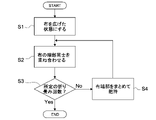
- FIG. 5 is a flowchart schematically showing the entire operation procedure of the robot device 10.
- the robot device 10 takes out the cloth C from the accommodating portion 2 and puts it in an unfolded state (deployed state) (step 1).
- the unfolding step of the cloth C includes an operation of gripping the end portion (corner portion in this example) of the cloth C.
- step 2 the process of overlapping and folding the edges (corners in this example) of the cloth is executed (step 2).
- the folding step of the cloth C is performed on the workbench 1 in the present embodiment as described later.
- the folding step is executed a predetermined number of times. For example, in the case of folding in half, it is once, and in the case of folding in four, it is twice.
- the number of times of folding is less than the predetermined number (No in step 3)
- the end portions (corners in this example) of the overlapping cloths C are grasped by the first and second hands 11 and 12, and the processes of steps 2 and 3 are performed. Execute again (step 4).
- the number of times of folding reaches a predetermined number of times (Yes in step 3)
- the folding process for the cloth C is completed, the cloth C is newly taken out from the accommodating portion 2, and the above process is repeatedly executed.
- This unfolding step includes a first operation process of taking out only one piece of cloth C from the accommodating portion 2 and a second operation process of unfolding the taken out cloth C.
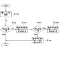
- FIG. 6 is a flowchart showing a procedure of the first operation processing executed in the control circuit 50. In the following description, unless otherwise specified, each process described later is executed based on the operation command output by the control circuit 50 (operation command generation unit 52).
- the robot device 10 grips the cloth C in the accommodating portion 2 with the first hand 11 (step 101).
- the first arm 21 conveys the cloth C to a predetermined height position above the accommodating portion 2.
- the predetermined height position is, for example, a height position where the lower end portion of the cloth C suspended from the first hand 11 does not come into contact with the other cloth C in the accommodating portion 2.
- the robot device 10 determines whether or not the number of cloths C gripped by the first hand 11 is one (step 102). This determination process is executed by the determination unit 53 of the control circuit 50. Whether or not the number of cloths C gripped by the first hand 11 is one can be determined based on the weight of the cloth C acting on the first hand 11. The weight of the cloth C may be detected based on the output of the first pressure distribution sensor 41, or the output of another force sensor configured separately from the first pressure distribution sensor 41 may be used.
- the robot device 10 grips the cloth C by the first hand 11.
- the cloth C to be used is changed to the second hand 12 (step 103).
- the second hand 12 may grip the cloth C at a position near the first hand 11 (for example, laterally or below the first hand 11).
- the detection of the cloth C by the second hand 12 can be performed based on the output of the second pressure distribution sensor 42.
- the robot device 10 further determines whether or not there is only one piece of cloth C transferred to the second hand 12 (step 104). Since the overlapping cloth C is likely to fall due to the operation of switching the cloth C from the first hand 11 to the second hand 12, the determination unit 53 further determines the weight of the cloth C gripped by the second hand 12. ..
- the cloth C is transferred from the second hand 12 to the first hand 11 and the next step (second operation process) is started (step 105). ).
- the number of cloths C held by the second hand 12 is switched to the first hand 11 and again by the first hand 11. Is determined (step 106). The operation of changing the cloth C is repeated between the first hand 11 and the second hand 12 until the number of cloths C becomes one.
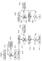
- FIG. 7 is a flowchart showing a procedure of the second operation processing executed in the control circuit 50.
- each process described later is executed based on the operation command output by the control circuit 50 (operation command generation unit 52).
- 8 to 12 are schematic views of the robot device 10 showing the procedure of the second operation process.
- the second operation process is started from the state where one cloth C is gripped by the first hand 11 by the above-mentioned first operation process.
- the second operation process is typically executed in the following procedure after the cloth C is conveyed at a position directly above the workbench 1.
- the control circuit 50 first generates an operation command (first grip command) for causing the second hand 12 to grip a predetermined portion (first predetermined portion) of the cloth C gripped by the first hand 11 (step 111). , Figure 9).
- the gripping command for the second hand 12 at this time is a weak gripping command in which the second hand 12 can move (slide) relative to the cloth C.
- the predetermined portion (first predetermined portion) is not particularly limited, but the vicinity of the gripping position of the cloth C by the first hand 11 is preferable. As a result, the gripping operation of the cloth C by the second hand 12 can be performed relatively easily.
- control circuit 50 determines whether or not the predetermined portion (first predetermined portion) of the cloth C gripped by the second hand 12 is the end portion of the cloth C, and is gripped by the second hand 12. It is determined whether or not the thickness of the cloth C is the thickness of one piece of the cloth C (step 112).
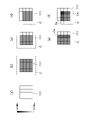
- FIG. 13 is a schematic diagram showing the relationship between the gripping position of the cloth C and the output of the second pressure distribution sensor 42.
- the detection surface S of the second pressure distribution sensor 42 is divided into a plurality of detection regions by a plurality of sensing units 29 (see FIG. 3).
- the entire detection surface S comes into contact with the cloth C, so that the second pressure distribution sensor 42 detects each of the detection surfaces S. Detects near constant pressure in the region. In this case, the determination unit 53 determines that the second hand 12 does not grip the end portion of the cloth C.
- the second pressure distribution sensor 42 detects different pressures depending on the detection region.
- the first region dark color region in the figure
- the pressure is equal to or larger than a predetermined value and the pressure.
- the boundary portion with the second region whose size is less than the predetermined value extends along at least an arbitrary uniaxial direction.
- the determination unit 53 determines that the second hand 12 is gripping the edge portion of the cloth C. Further, as shown in FIG. 13D, when the determination unit 53 determines that the boundary portion between the first region and the second region extends along the biaxial direction in which they intersect each other, the determination unit 53 determines. It is determined that the second hand 12 is gripping the corner portion of the cloth C.
- the predetermined value is not particularly limited, and is typically set to a value capable of distinguishing the contact region with the cloth C and the non-contact region.
- the pressure value in the detection region corresponding to the folded portion Ce is higher than the pressure value in the other detection regions, as shown in FIGS. 13 (e) and 13 (f). Will also grow. Even in such a case, by setting the contact area with the folded-back portion Ce as the first region, it is determined whether or not the end portion (edge portion, corner portion) of the cloth C is located on the detection surface S. can do.
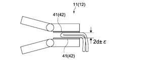
- the thickness of the cloth C gripped by the second hand 12 is detected based on the facing distance between the gripping surfaces of the second hand 12. For example, assuming that the average thickness of one piece of cloth C is d, when the thickness of cloth C gripped by the second hand 12 corresponds to the thickness of one piece of cloth C, as shown in FIG. 14, the second hand 12 The facing distance between the gripping surfaces is d ⁇ ⁇ ( ⁇ is an arbitrary value less than d). When the thickness of the cloth C gripped by the second hand 12 corresponds to the thickness of two pieces, the facing distance between the gripping surfaces of the second hand 12 is 2d ⁇ as shown in FIGS. 15 and 16. It becomes ⁇ . Note that FIG. 15 shows a state when two cloths C are gripped at the same time, and FIG. 16 shows a state where one cloth C is gripped in a folded state.
- the thickness of the cloth C gripped by the first hand 11 can also be detected in the same manner as described above. In this way, the facing distances between the gripping surfaces are generally discrete. Therefore, by acquiring the facing distance data between the gripping surfaces corresponding to the number of cloths C in advance, the first and second hands 11 and 12 The number of cloths C to be gripped can be determined.
- the outputs of the first and second pressure distribution sensors 41 and 42 are referred to for determining whether or not the thickness of the cloth C gripped by the first and second hands 11 and 12 corresponds to the thickness of one sheet. May be done.
- the outputs (hereinafter, also referred to as reference values) of the first and second pressure distribution sensors 41 and 42 when one cloth C is gripped with a constant gripping force are stored in advance.
- the thickness of the gripped cloth C is two or more. Can be determined to be.
- the control circuit 50 performs a weak gripping operation of the cloth C by the second hand 12.
- the operation command (first movement command) for moving (sliding) the second hand 12 relative to the cloth C in a predetermined direction from the first predetermined portion is generated (step 113).
- the first hand 11 grips the cloth C with a relatively strong gripping force so as not to move with respect to the cloth C.
- the second hand 12 is separated from the first hand 11 while applying a constant tension to the cloth C between the first hand 11 and the second hand 12.
- the moving speed of the second hand 12 is not particularly limited, and typically, the second hand 12 is moved relative to the first hand 11 and the cloth C at a constant speed.
- the moving direction of the second hand 12 (the predetermined direction) is not particularly limited, but in the present embodiment, it is downward (gravity direction) (see FIG. 10).
- the determination unit 53 determines whether or not the second hand 12 has reached the end of the cloth C based on the output of the second pressure distribution sensor 42 (step 112). For example, when the gripping start position (first predetermined portion) of the second hand 12 is not the end of the cloth C, when the second hand 12 is slid downward with respect to the cloth C, the cloth C is finally held. Reach the bottom edge (edge or corner) of. Therefore, the determination unit 53 determines that the second hand 12 has reached the end of the cloth C when the pressure distribution as shown in FIGS. 13 (c) to 13 (f) is output from the second pressure distribution sensor 42. judge.
- the second hand 12 is slid downward with respect to the cloth C. Typically, it goes beyond the overlapping area of the cloth C and reaches the thickness area of one piece of the cloth C. That is, the overlapping area of the cloth C is randomly generated, but the overlapping area rarely continues to the lower end of the cloth C. In particular, since the second hand 12 is moved downward, the lower end portion of the cloth C is easily exposed due to the self-weight action of the cloth C, and it is easy to determine whether or not the second hand 12 has reached the lower end portion of the cloth C. .. If the thickness of the cloth C to be gripped by the second hand 12 is not the thickness corresponding to one sheet even at the lower end of the cloth C, the operation of step 113 described above is repeated again.
- the control circuit 50 stops the movement of the second hand 12, and the gripping force with respect to the cloth C at that position is given from the weak grip command. Change to a strong grip command (step 114). As a result, the lower end portion of the cloth C is stably gripped by the second hand 12. After that, the control circuit 50 generates an operation command for releasing the gripping operation of the cloth C with respect to the first hand 11, and releases the first hand 11 from the cloth C (step 115). At this time, the vertical positions of the first hand 11 and the second hand 12 may be reversed, and the position of the second hand 12 may be changed so that the second hand 12 is located above the first hand 11.
- the control circuit 50 causes the first hand 11 to grip a predetermined portion (second predetermined portion) near the end of the cloth C gripped by the second hand 12 (second grip command). ) (Step 116).
- the gripping command for the first hand 11 at this time is a weak gripping command in which the first hand 11 can move (slide) relative to the cloth C.
- the predetermined portion (second predetermined portion) is not particularly limited, but the vicinity of the gripping position of the cloth C by the second hand 12 is preferable. As a result, the gripping operation of the cloth C by the first hand 11 can be performed relatively easily.
- control circuit 50 determines whether or not the predetermined portion (second predetermined portion) of the cloth C gripped by the first hand 11 is the end portion of the cloth C, and is gripped by the first hand 11. It is determined whether or not the thickness of the cloth C is the thickness of one piece of the cloth C (step 117). Since the determination of the gripping position and the thickness of the cloth C by the first hand 11 is the same as in step 112 described above, the description thereof is omitted here.
- the control circuit 50 determines.
- the gripping position of the cloth C by the first hand 11 is changed to generate an operation command for gripping another portion again (step 118).
- the predetermined portion (second predetermined portion) of the cloth C gripped by the first hand 11 is the end portion of the cloth C
- the thickness of the cloth C gripped by the first hand 11 is the cloth. It is repeatedly executed until it is determined that the thickness is one sheet of C.
- step 113 the same process as in step 113 may be executed. That is, an operation command for moving (sliding) the first hand 11 relative to the cloth C in the second predetermined direction from the second predetermined portion while maintaining the weak gripping operation of the cloth C by the first hand 11. (Second movement command) may be generated.
- control circuit 50 directs the first hand 11 toward the corner of the cloth C and attaches the first hand 11 to the cloth C at a constant speed while maintaining the gripping motion (weak gripping motion) of the end portion of the cloth C by the first hand 11. Further, an operation command (second movement command) for relative movement is generated (step 119).
- the first hand 11 grips the end (typically the edge) of the cloth C in the vicinity of the second hand 12, the first hand 11 is the edge of the cloth C gripped by the second hand 12. It is highly probable that it is gripping on the same side as. Further, the cloth C is suspended in the direction of gravity starting from the second hand 12. Therefore, the moving direction of the first hand 11 is preferably a direction away from the first hand 12 in the direction of gravity. The moving direction of the first hand 11 may be a direction horizontally separated from the second hand 12.
- the moving direction of the first hand 11 may be determined based on the pressure distribution detected by the first pressure distribution sensor 41. For example, when the pressure distribution as shown in FIG. 13C is detected by the first pressure distribution sensor 41, the boundary portion between the first region (contact region) and the second region (non-contact region) is set. The moving direction of the first hand 11 is determined in the extending direction (vertical direction in FIG. 13C). As a result, the first hand 11 can be moved toward the corner of the cloth C.
- the determination unit 53 determines whether or not the first hand 11 has reached the corner of the cloth C based on the output of the first pressure distribution sensor 41 (step 120).
- the control circuit 50 stops the movement of the first hand 11 and changes the gripping force with respect to the cloth C at that position from the weak gripping command to the strong gripping command. (Step 121). As a result, one corner of the cloth C is stably gripped by the first hand 11.
- control circuit 50 drives the first arm 21 and the second arm 22 so that the first hand 11 and the second hand 12 face each other in the horizontal direction, respectively. Is generated (step 122).
- the determination unit 53 determines whether or not the second hand 12 grips the end of the cloth C and the thickness of the cloth C is the thickness of one of the cloths C (step 123).
- the control circuit 50 determines.
- the gripping position of the cloth C by the second hand 12 is changed to generate an operation command for re-grasping the end portion (typically, the edge portion) of the cloth C in the vicinity of the first hand 11 (step 124). Since the conditions of step 123 are typically satisfied by the above-mentioned processes of steps 112 to 114, steps 123 and 124 are processes for confirmation and may be omitted if necessary. ..
- the control circuit 50 changes the grip command of the second hand 12 with respect to the cloth C from the strong grip command to the weak grip command. Then, the control circuit 50 holds the second hand 12 with the corner portion of the cloth C gripped by the first hand 11 while maintaining the gripping motion (weak gripping motion) of the end portion of the cloth C by the second hand 12.
- An operation command (third movement command) for moving the cloth C relative to the cloth C at a constant speed is generated toward the other adjacent corners (step 125, FIG. 11).
- the moving direction of the second hand 12 is typically a direction horizontally separated from the first hand 11.
- the moving direction of the second hand 12 can be determined based on the pressure distribution detected by the second pressure distribution sensor 42, as in step 119 described above.
- the determination unit 53 determines whether or not the second hand 12 has reached the corner of the cloth C based on the output of the second pressure distribution sensor 42 (step 126).
- the control circuit 50 stops the movement of the second hand 12 and changes the gripping force with respect to the cloth C at that position from the weak gripping command to the strong gripping command. ..
- the other corner portion of the cloth C is stably gripped by the first hand 11 (see FIG. 12).
- the robot device 10 performs the unfolding operation of the cloth C.
- the cloth C by the other hand is moved by moving the other hand relative to the cloth C while grasping the cloth C by one of the first and second hands 11 and 12. It is possible to detect the end of the cloth and grasp it. Therefore, even when the cloth C is placed randomly, the end portion of the cloth C can be detected and gripped.
- one of the first and second hands 11 and 12 grips the end of the cloth C, while the other hand detects and grips the corner of the cloth C. Therefore, the operation of gripping the two corners of the cloth C by the first and second hands 11 and 12, which is necessary for the operation of unfolding the cloth C, can be automatically performed.
- the control circuit 50 generates a folding command for superimposing the corners of the cloth C on each other.
- the control circuit 50 has the first corner gripped by the first hand 11.
- the portion C1 is superposed on the first corner portion C1 and the second corner portion C2 facing the gravity direction (vertical direction), and the third corner portion C3 gripped by the second hand 12 is combined with the third corner portion C3 by gravity.
- the operation of superimposing on the fourth corner portion C4 facing in the direction (vertical direction) is executed.
- the control circuit 50 holds (strongly grips) the first corner portion C1 and the third corner portion C3 located at both ends of the upper side of the cloth C by the first hand 11 and the second hand 12, respectively.
- the cloth C is moved directly above the workbench 1.
- the first hand 11 and the second hand 12 are arranged on an axis parallel to the Y-axis direction with a constant tension applied to the cloth C, and the lower end portion of the cloth C works. It is arranged at a height position that does not touch the table 1.
- control circuit 50 simultaneously moves the first and second hands 11 and 12 downward in the Z-axis direction until the lower end of the cloth C touches the workbench 1. Whether or not the lower end portion of the cloth C touches the workbench 1 can be detected by the weight change of the cloth C acting on the first and second hands 11 and 12.
- the control circuit 50 After the contact of the cloth C with the workbench 1 is detected, the control circuit 50 lowers the first and second hands 11 and 12 by the same amount of movement as the lowering amount, and the first and second hands 11 and 12. 12 is moved toward the front (the negative direction of the X-axis in FIG. 12) when viewed from the robot device 10. This operation continues until it reaches half the length of the cloth C in the vertical direction.
- the length of each side of the cloth C is stored in the storage unit 54 as a known value. Therefore, the vertical length of the cloth C can be determined by the distance between the corner portions C1 and C3 gripped by the first and second hands 11 and 12.
- the length of each side of the cloth C does not necessarily have to be known, and may be detected by a separate method.
- the vertical length of the cloth C can be detected at the height positions of the first and second hands 11 and 12 when the cloth C touches the work table 1, and the cloth C is horizontal. As for the direction, it can be detected at the horizontal positions of the first and second hands 11 and 12 that grip the corners C1 and C2.
- the control circuit 50 After placing the cloth C on the workbench 1 to half the length of the cloth C, the control circuit 50 reverses the moving direction of the first and second hands 11 and 12 along the X-axis direction, and the first and second hands 11 and 12 are reversed. While lowering the hands 11 and 12, they are moved in the back direction (positive direction of the X axis in FIG. 12) when viewed from the robot device 10. By continuing the operation as it is, the corners C1 and C3 overlap with the corners C2 and C4 on the workbench 1, respectively, and the cloth C is folded in half.
- the control circuit 50 holds (strongly grips) the first corner portion C1 and the third corner portion C3 located at both ends of the upper side of the cloth C by the first hand 11 and the second hand 12, respectively.
- the lower end of the cloth C is moved toward the back of the robot device 10 to a position where it gets over the rod PP.
- the first hand 11 and the second hand 12 are arranged on an axis parallel to the Y-axis direction, for example, with a constant tension applied to the cloth C.
- control circuit 50 moves the first and second hands 11 and 12 in the Z-axis direction so that the central position of the vertical length of the cloth C is at the height position of the rod P. Then, the control circuit 50 moves the first and second hands 11 and 12 toward the front of the robot device 10 until the center position of the vertical length of the cloth C comes into contact with the rod PP.
- the first is along an arc orbit centered on the rod PP and having a length of half the length of the cloth C in the vertical direction as a radius while maintaining the tension of the cloth C.
- the second hands 11 and 12 are moved in the XZ plane.
- the rotation angles of the first and second hands 11 and 12 on the arc orbit are set to about 180 degrees. Whether or not the cloth C touches the rod PP can be detected by the weight change of the cloth C acting on the first and second hands 11 and 12.
- the control circuit 50 releases the gripping operation of the first and second hands 11 and 12 with respect to the cloth C.
- the corner portions C1 and C3 are superimposed on the corner portions C2 and C4 in the X-axis direction, respectively.
- the cloth C folded in half in the vertical direction is taken out from the rod PP by grasping and lifting both left and right ends of the cloth C resting on the rod PP with the first and second hands 11 and 12. Can be done.
- the robot device 10 configured to be able to fold the rectangular cloth C in half has been described as an example, but the present invention is not limited to this, and various methods for handling flexible thin bodies have been described.
- This technology can be applied to applications.
- this technique uses the work of finding and grasping the edges and corners of cloth such as sheets, towels, and yukata that have been randomly piled up after washing or drying, the work of loading the above cloth into a commercial iron or folding device, and the sheets. It can be applied to work such as hanging and removing such as from a predetermined position on a bed or the like.
- the robot device 10 has been described by exemplifying a dual-arm type robot device provided with a first arm 21 and a second arm 22 as an example, but the present invention is not limited to this, and three or more arms are described. A robot having the above may be adopted.
- the first and second finger units 110 and 120 provided in the first and second hands 11 and 12 are not limited to the two-finger gripper, and a finger unit having three or more finger portions may be adopted. ..
- the present technology can have the following configurations.
- An acquisition unit that acquires the output of the first pressure distribution sensor arranged on the gripping surface of the first hand and the output of the second pressure distribution sensor arranged on the gripping surface of the second hand.
- the first gripping command for causing the second hand to grip the first predetermined portion of the flexible thin body gripped by the first hand, and the gripping operation of the flexible thin body by the second hand are maintained.
- an operation command generation unit that generates a first movement command for relatively moving the second hand from the first predetermined portion in a predetermined direction with respect to the flexible thin body.
- a control device including a determination unit for determining whether or not the second hand has reached the end of the flexible thin body based on the output of the second pressure distribution sensor.
- the operation command generation unit further generates a second grip command that causes the first hand to grip a second predetermined portion near the end of the flexible thin body gripped by the second hand.
- the determination unit is a control device that further determines whether or not the second predetermined portion is an end portion of the flexible thin body based on the output of the first pressure distribution sensor.
- the operation command generation unit While maintaining the gripping operation of the flexible thin body by the first hand, the operation command generation unit directs the first hand toward the corner portion of the flexible thin body and makes the flexible thin body into the flexible thin body.
- a control device that further generates a second movement command to move relative to each other.
- the operation command generation unit is in a state of gripping one corner of the movable thin body by the first hand, and while maintaining the gripping operation of the flexible thin body by the second hand, the second hand.
- a control device that further generates a third movement command that moves the hand relative to the flexible thin body toward the other corners of the flexible thin body.
- the control device according to any one of (1) to (5) above.
- the control device whose predetermined direction is the direction of gravity.
- the control device according to any one of (1) to (6) above.
- the acquisition unit further acquires information regarding the facing distance between the gripping surfaces of the second hand that grips the first predetermined portion.
- the determination unit determines whether or not the first predetermined portion held by the second hand is the thickness of one flexible thin body based on the information regarding the facing distance.
- Device (8) The control device according to any one of (1) to (7) above. Based on the pressure distribution detected by the second pressure distribution sensor, the determination unit has a first region in which the pressure magnitude is equal to or greater than a predetermined value and a second region in which the pressure magnitude is less than the predetermined value.
- a control device for determining that the second hand has reached the end of the flexible thin body when it is determined that the boundary portion with and is extended along at least an arbitrary uniaxial direction (9) The control device according to (8) above. When the determination unit determines that the boundary between the first region and the second region extends along a biaxial direction in which they intersect each other, the second hand is the flexible thin body. A control device that determines that the corner of the is reached. (10) The control device according to (2) above. Based on the pressure distribution detected by the first pressure distribution sensor, the determination unit has a first region in which the pressure magnitude is equal to or greater than a predetermined value and a second region in which the pressure magnitude is less than the predetermined value.
- a control device that determines that the second predetermined portion is an end portion of the flexible thin body when it is determined that the boundary portion between the two and is extended along at least an arbitrary uniaxial direction.
- the acquisition unit further acquires information regarding the weight of the flexible thin body gripped by the first hand. Based on the information regarding the weight, the determination unit determines whether or not the weight of the flexible thin body held by the first hand is the weight of one of the flexible thin bodies.
- Control device (12) The control device according to (5) above.
- the operation command generation unit is a control device that further generates a folding command for superimposing the corner portions of the flexible thin body on each other. (13) The control device according to (12) above.
- the folding command superimposes the first corner portion gripped by the first hand on the second corner portion facing the first corner portion in the direction of gravity, and the third corner portion gripped by the second hand.
- a control device for executing an operation of superimposing the third corner portion on the fourth corner portion facing in the direction of gravity.
- a first hand having a first pressure distribution sensor arranged on the grip surface, A second hand with a second pressure distribution sensor located on the grip surface, An acquisition unit that acquires the output of the first pressure distribution sensor and the output of the second pressure distribution sensor.
- the first gripping command for causing the second hand to grip the first predetermined portion of the flexible thin body gripped by the first hand, and the gripping operation of the flexible thin body by the second hand are maintained.
- an operation command generation unit that generates a first movement command for relatively moving the second hand from the first predetermined portion in a predetermined direction with respect to the flexible thin body.
- a robot device including a control circuit having a determination unit for determining whether or not the second hand has reached the end of the flexible thin body based on the output of the second pressure distribution sensor.
- the second hand grips the first predetermined portion of the flexible thin body gripped by the first hand. While maintaining the gripping operation of the flexible thin body by the second hand, the second hand is moved relative to the flexible thin body in a predetermined direction from the first predetermined portion.
- a control method for a robot device that determines whether or not the second hand has reached the end of the flexible thin body based on the output of a pressure distribution sensor arranged on the gripping surface of the second hand.
- a step of causing the second hand to grip the first predetermined portion of the flexible thin body gripped by the first hand A step of moving the second hand relative to the flexible thin body in a predetermined direction from the first predetermined portion while maintaining the gripping operation of the flexible thin body by the second hand.
Landscapes
- Engineering & Computer Science (AREA)
- Robotics (AREA)
- Mechanical Engineering (AREA)
- Human Computer Interaction (AREA)
- Health & Medical Sciences (AREA)
- General Health & Medical Sciences (AREA)
- Orthopedic Medicine & Surgery (AREA)
- Manipulator (AREA)
Priority Applications (2)
| Application Number | Priority Date | Filing Date | Title |
|---|---|---|---|
| JP2022556998A JPWO2022085514A1 (https=) | 2020-10-22 | 2021-10-12 | |
| US18/248,514 US20230381972A1 (en) | 2020-10-22 | 2021-10-12 | Control apparatus, robot apparatus, control method and program for a robot apparatus |
Applications Claiming Priority (2)
| Application Number | Priority Date | Filing Date | Title |
|---|---|---|---|
| JP2020-177283 | 2020-10-22 | ||
| JP2020177283 | 2020-10-22 |
Publications (1)
| Publication Number | Publication Date |
|---|---|
| WO2022085514A1 true WO2022085514A1 (ja) | 2022-04-28 |
Family
ID=81290484
Family Applications (1)
| Application Number | Title | Priority Date | Filing Date |
|---|---|---|---|
| PCT/JP2021/037697 Ceased WO2022085514A1 (ja) | 2020-10-22 | 2021-10-12 | 制御装置、ロボット装置、ロボット装置の制御方法およびプログラム |
Country Status (3)
| Country | Link |
|---|---|
| US (1) | US20230381972A1 (https=) |
| JP (1) | JPWO2022085514A1 (https=) |
| WO (1) | WO2022085514A1 (https=) |
Cited By (1)
| Publication number | Priority date | Publication date | Assignee | Title |
|---|---|---|---|---|
| JP2024108951A (ja) * | 2023-01-31 | 2024-08-13 | 国立大学法人山形大学 | 柔らかさ測定装置、柔らかさ測定方法、ロボット把持部の把持力制御装置、ロボット制御装置、ロボット、及びロボット把持部の把持力制御用プログラム |
Families Citing this family (4)
| Publication number | Priority date | Publication date | Assignee | Title |
|---|---|---|---|---|
| JP7278930B2 (ja) * | 2019-11-29 | 2023-05-22 | 川崎重工業株式会社 | 保持装置、ロボット、及びロボットシステム |
| US12024815B2 (en) | 2021-07-16 | 2024-07-02 | Mihir Kothari | System and method of laundry sorting |
| US20250128425A1 (en) * | 2021-09-22 | 2025-04-24 | Sony Group Corporation | Robot apparatus and control method therefor |
| US12584268B2 (en) * | 2022-09-13 | 2026-03-24 | Mihir Kothari | System and method of laundry singulation and flattening |
Citations (3)
| Publication number | Priority date | Publication date | Assignee | Title |
|---|---|---|---|---|
| JP2002321869A (ja) * | 2001-04-25 | 2002-11-08 | Hakko Shokai:Kk | タオル等の折り畳み方法及び装置 |
| JP2003094377A (ja) * | 2001-09-25 | 2003-04-03 | Ricoh Co Ltd | 作業用ロボットのハンドと作業用ロボットと作業用ロボットの制御装置及び作業用ロボットの処理プログラムを記憶した外部記憶媒体 |
| JP2013142017A (ja) * | 2012-01-10 | 2013-07-22 | Bridgestone Corp | 樹脂シートの積層装置及び積層方法 |
-
2021
- 2021-10-12 JP JP2022556998A patent/JPWO2022085514A1/ja not_active Abandoned
- 2021-10-12 US US18/248,514 patent/US20230381972A1/en not_active Abandoned
- 2021-10-12 WO PCT/JP2021/037697 patent/WO2022085514A1/ja not_active Ceased
Patent Citations (3)
| Publication number | Priority date | Publication date | Assignee | Title |
|---|---|---|---|---|
| JP2002321869A (ja) * | 2001-04-25 | 2002-11-08 | Hakko Shokai:Kk | タオル等の折り畳み方法及び装置 |
| JP2003094377A (ja) * | 2001-09-25 | 2003-04-03 | Ricoh Co Ltd | 作業用ロボットのハンドと作業用ロボットと作業用ロボットの制御装置及び作業用ロボットの処理プログラムを記憶した外部記憶媒体 |
| JP2013142017A (ja) * | 2012-01-10 | 2013-07-22 | Bridgestone Corp | 樹脂シートの積層装置及び積層方法 |
Cited By (1)
| Publication number | Priority date | Publication date | Assignee | Title |
|---|---|---|---|---|
| JP2024108951A (ja) * | 2023-01-31 | 2024-08-13 | 国立大学法人山形大学 | 柔らかさ測定装置、柔らかさ測定方法、ロボット把持部の把持力制御装置、ロボット制御装置、ロボット、及びロボット把持部の把持力制御用プログラム |
Also Published As
| Publication number | Publication date |
|---|---|
| JPWO2022085514A1 (https=) | 2022-04-28 |
| US20230381972A1 (en) | 2023-11-30 |
Similar Documents
| Publication | Publication Date | Title |
|---|---|---|
| WO2022085514A1 (ja) | 制御装置、ロボット装置、ロボット装置の制御方法およびプログラム | |
| JP5299934B2 (ja) | 変形性薄物展開装置および変形性薄物展開方法 | |
| Elbrechter et al. | Folding paper with anthropomorphic robot hands using real-time physics-based modeling | |
| JP6511715B2 (ja) | ロボット制御装置、ロボットシステム、及びロボット | |
| JP2009279700A (ja) | ワークの把持方法および装置 | |
| JP4834767B2 (ja) | 把持装置、布地処理ロボットおよび布地処理システム | |
| JP6661925B2 (ja) | 制御装置、ロボットおよびロボットシステム | |
| JP7339793B2 (ja) | ロボットシステム | |
| JP2015182142A (ja) | ロボット、ロボットシステム及び教示方法 | |
| Digumarti et al. | Dexterous textile manipulation using electroadhesive fingers | |
| Koyama et al. | Integrated control of a multi-fingered hand and arm using proximity sensors on the fingertips | |
| Kudo et al. | Multi-arm robot control system for manipulation of flexible materials in sewing operation | |
| Koustoumpardis et al. | A 3-finger robotic gripper for grasping fabrics based on cams-followers mechanism | |
| CN116917088B (zh) | 机器人仿真装置 | |
| JP5785756B2 (ja) | 布類の展開方法 | |
| Lee et al. | Gog: A versatile gripper-on-gripper design for bimanual cloth manipulation with a single robotic arm | |
| US9929680B2 (en) | Conformable electroadhesive holding device | |
| WO2023047630A1 (ja) | ロボット装置およびその制御方法 | |
| Shibata et al. | Handling of hemmed fabrics by a single-armed robot | |
| Shibata et al. | Wiping motion for deformable object handling | |
| JP6829129B2 (ja) | 柔軟シート展開装置 | |
| Kondo et al. | Development and control of robot hand with finger camera for garment handling tasks | |
| Shaqura et al. | A novel gripper design for multi hand tools grasping under tight clearance constraints and external torque effect | |
| JP2020131403A (ja) | ロボットの制御方法、制御装置及びロボットシステム | |
| Fujihara et al. | An End-Effector for Pinch and Slide Unfolding Using a Protruding Passive Rotation Mechanism |
Legal Events
| Date | Code | Title | Description |
|---|---|---|---|
| 121 | Ep: the epo has been informed by wipo that ep was designated in this application |
Ref document number: 21882655 Country of ref document: EP Kind code of ref document: A1 |
|
| ENP | Entry into the national phase |
Ref document number: 2022556998 Country of ref document: JP Kind code of ref document: A |
|
| NENP | Non-entry into the national phase |
Ref country code: DE |
|
| 122 | Ep: pct application non-entry in european phase |
Ref document number: 21882655 Country of ref document: EP Kind code of ref document: A1 |