WO2022085347A1 - ガラス板の製造方法 - Google Patents
ガラス板の製造方法 Download PDFInfo
- Publication number
- WO2022085347A1 WO2022085347A1 PCT/JP2021/034549 JP2021034549W WO2022085347A1 WO 2022085347 A1 WO2022085347 A1 WO 2022085347A1 JP 2021034549 W JP2021034549 W JP 2021034549W WO 2022085347 A1 WO2022085347 A1 WO 2022085347A1
- Authority
- WO
- WIPO (PCT)
- Prior art keywords
- concave line
- glass plate
- protrusion
- initial crack
- base portion
- Prior art date
- Legal status (The legal status is an assumption and is not a legal conclusion. Google has not performed a legal analysis and makes no representation as to the accuracy of the status listed.)
- Ceased
Links
Images






Classifications
-
- B—PERFORMING OPERATIONS; TRANSPORTING
- B26—HAND CUTTING TOOLS; CUTTING; SEVERING
- B26F—PERFORATING; PUNCHING; CUTTING-OUT; STAMPING-OUT; SEVERING BY MEANS OTHER THAN CUTTING
- B26F3/00—Severing by means other than cutting; Apparatus therefor
-
- B—PERFORMING OPERATIONS; TRANSPORTING
- B28—WORKING CEMENT, CLAY, OR STONE
- B28D—WORKING STONE OR STONE-LIKE MATERIALS
- B28D5/00—Fine working of gems, jewels, crystals, e.g. of semiconductor material; apparatus or devices therefor
-
- C—CHEMISTRY; METALLURGY
- C03—GLASS; MINERAL OR SLAG WOOL
- C03B—MANUFACTURE, SHAPING, OR SUPPLEMENTARY PROCESSES
- C03B33/00—Severing cooled glass
- C03B33/02—Cutting or splitting sheet glass or ribbons; Apparatus or machines therefor
- C03B33/023—Cutting or splitting sheet glass or ribbons; Apparatus or machines therefor the sheet or ribbon being in a horizontal position
- C03B33/033—Apparatus for opening score lines in glass sheets
Definitions
- the present invention relates to a method for manufacturing a glass plate.
- a glass plate for a panel display such as a liquid crystal display or an organic EL display
- a glass plate of a predetermined size is formed by cutting a large mother glass formed by a molding method such as a down draw method. do.
- Patent Document 1 describes, as a method for manufacturing a glass plate, a concave line forming step of forming a concave line by plastic deformation on the surface of a mother glass, and an initial crack forming step of forming an internal initial crack at a position corresponding to the concave line.
- a crack growing step of developing an internal initial crack inside the mother glass along a concave line and a folding step of breaking the mother glass along the concave line are disclosed.
- the concave wire formed by the concave wire forming step includes a compressive stress layer formed by plastic deformation and a tensile stress layer formed on the inner side of the mother glass from the compressive stress layer.
- the scribe wheel is brought into contact with the surface of the mother glass and moved in the direction intersecting the concave line. As a result, a scribe line intersecting the concave line is formed on the mother glass. Starting from this scribe line, internal initial cracks are formed in the tensile stress layer (see paragraphs 0030 and 0031 of the same document and FIG. 8).
- crack growth step cracks originating from this internal initial crack are grown in the concave tensile stress layer. After that, by executing the folding step, it is possible to manufacture a glass plate in which lateral cracks do not occur on the end face.
- a scribe wire by a scribe wheel is formed on the mother glass in order to form an internal initial crack. Since the scribe wire contains a large number of lateral cracks, it is necessary to separate the portion of the mother glass in which the scribe wire is formed from the glass plate and discard it in the folding step.
- the present invention has been made in view of the above circumstances, and it is a technical subject to cut the mother glass so that lateral cracks do not occur on the cut surface and to improve the yield of the glass plate.
- the present invention is for solving the above-mentioned problems, and in a method for manufacturing a glass plate including a cutting step for cutting a mother glass, the cutting step forms a concave line due to plastic deformation on the surface of the mother glass.
- the concave line is provided with a concave line forming step, an initial crack forming step of forming an initial crack in the concave line, and a crack growing step of developing the initial crack inside the mother glass along the concave line.
- the concave line without lateral cracks can be formed by plastically deforming the surface of the mother glass.
- an initial crack can be formed in the protrusion by scratching at least one of the first base portion and the second base portion of the protrusion.
- a glass plate having no lateral crack on the end face (cut surface) can be manufactured by growing the crack starting from the initial crack along the concave line.
- the mother glass can be cut without forming a scribe line intersecting the concave line, it is possible to reduce the amount of glass discarded in the cutting process as much as possible. This makes it possible to improve the yield of the glass plate.
- the protrusion includes a first protrusion located at one end of the concave line in the width direction and a second protrusion located at the other end of the concave line in the width direction.
- the first protrusion or the second protrusion may be scratched.
- the scratch along the width direction of the concave line may be made on the protrusion.
- initial cracks can be easily formed on the protrusions.
- the scratch may be made by bringing the tip-shaped tool into contact with at least one of the first base portion and the second base portion.
- the tool may be vibrated. As a result, initial cracks can be reliably formed on the protrusions.
- the mother glass can be cut so that lateral cracks do not occur on the cut surface, and the yield of the glass plate can be improved.
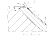
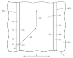
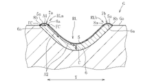
- FIG. 5 is a sectional view taken along line VI-VI of FIG. It is an enlarged sectional view of the main part of a mother glass plate. It is sectional drawing which shows the initial crack formation process in the manufacturing method of a glass plate. It is a top view which shows the crack growth process in the manufacturing method of a glass plate. It is sectional drawing which shows the crack growth process in the manufacturing method of a glass plate.
- FIG. 1 to 14 show an embodiment of a method for manufacturing a glass plate according to the present invention.
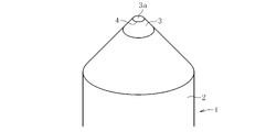
- FIGS. 1 to 3 show scribe chips used to form concave lines on the mother glass in this method.
- the pencil type scribe chip 1 is exemplified, but the configuration of the scribe chip is not limited to the present embodiment.
- the scribe tip 1 has a shank 2 and a tip 3 fixed to an end portion of the shank 2.
- the shank 2 is made of metal and is composed of a columnar or polygonal column.
- the shank 2 is attached to the holder H.
- the holder H holds the shank 2 and moves the scribe tip 1 in the vertical direction and the horizontal direction. Further, the holder H can freely change the inclination angle of the shank 2 with respect to the mother glass G.
- the chip 3 is composed of, for example, a single crystal or polycrystal diamond chip, but is not limited to this, and may be composed of PCBN, ceramic, cemented carbide or other metal.
- the chip 3 is fixed to the tip of the shank 2 with an adhesive, a brazing material, or the like.
- the chip 3 is formed in a truncated cone shape, and a pressing portion 4 in contact with the mother glass G is formed at the end thereof. That is, the edge portion of the end surface 3a of the chip 3 in the axial direction is the pressing portion 4.
- the pressing portion 4 is configured in an arc shape so as not to generate lateral cracks in the mother glass G.
- the pressing portion 4 is plastically deformed by pressing the surface of the mother glass G, and a concave line RL is formed in the plastically deformed portion.
- the radius (radius of curvature) of the pressing portion 4 is preferably 0.001 mm to 1 mm, more preferably 0.025 mm to 0.5 mm.
- This circular pressing portion 4 can be regarded as being composed of a plurality of arcs.
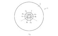
- the pressing portion 4 is virtually configured by three arcs 4a to 4c.
- the central angle ⁇ a of each arc 4a to 4c is set to 120 °, but is not limited to this, and it is desirable that the central angle ⁇ a is 5 ° to 120 °.
- the central angles ⁇ a of the arcs 4a to 4c are set to be equal, they may be configured at different angles.
- the mother glass G used in this method connects the first main surface Ga and the second main surface Gb, which are in a front-to-back relationship, and the first main surface Ga and the second main surface Gb. It is provided with an end face Gc.
- at least one of the first main surface Ga and the second main surface Gb is referred to as the "surface" of the mother glass G.
- the thickness t of the mother glass G is preferably 0.01 mm to 1 mm, more preferably 0.01 mm to 0.7 mm.
- the mother glass G has a size of 1000 mm or more on a side, but is not limited to this dimension.
- the mother glass G can be molded by various molding methods such as a known float method, rollout method, slot down draw method, and redraw method, but it is preferably molded by the overflow down draw method.
- the overflow down draw method molten glass is poured into an overflow groove provided in the upper part of a molded body having a substantially wedge-shaped cross section, and the molten glass overflowing from the overflow groove on both sides is flowed along the side walls on both sides of the molded body. While flowing down, it is fused and integrated at the lower end of the molded body to continuously form a single strip of glass. By cutting a part of the strip-shaped glass in the width direction, a rectangular mother glass G is formed.
- the manufacturing method of the glass plate will be described below.
- a rectangular glass plate is manufactured from a rectangular mother glass G made of non-alkali glass (OA-10G manufactured by Nippon Electric Glass Co., Ltd.) will be described.
- This method includes a cutting step of cutting the mother glass G.
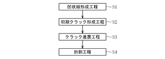
- the cutting step is initially performed on the concave line forming step S1 for forming the concave line RL by plastic deformation on the surface of the mother glass G (for example, the first main surface Ga) by the scribing chip 1 and the concave line RL.
- the initial crack forming step S2 for forming a crack, the crack growing step S3 for advancing the initial crack into the inside of the mother glass G along the concave line RL, and the breaking step S4 for applying bending stress to the mother glass G are performed. Be prepared.
- the mother glass G is placed on a mounting table (not shown), and the scribe chip 1 is brought into contact with the first main surface Ga of the mother glass G. It is desirable that a resin sheet is placed on the mounting table and the mother glass G is placed on the resin sheet.
- the scribe tip 1 is supported by the holder H so that the shank 2 is tilted with respect to the mother glass G.
- the tilt angle ⁇ b is preferably 30 ° to 85 °, but is not limited to this range.
- the moving speed of the scribe chip 1 is preferably 50 mm / s to 1500 mm / s.
- the load applied to the scribe chip 1 is 0.1N to 10N, but is not limited to this range, and is appropriately set according to conditions such as the size, thickness, and material of the mother glass G.
- the pressing portion 4 (the portion of the arc 4a) is arranged in a direction orthogonal to the moving direction X (so that the tangent line related to the arc 4a and the moving direction X are orthogonal to each other) (see FIG. 2).
- a part of the first main surface Ga is plastically deformed by the pressing of the pressing portion 4.
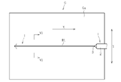
- the movement of the pressing portion 4 forms a linear concave line RL in the plastically deformed portion of the first main surface Ga.
- the direction orthogonal to the longitudinal direction (moving direction X) of the concave line RL is referred to as the width direction Y of the concave line RL.
- the width dimension W1 (see FIG. 6) related to the width direction Y of the concave line RL is 10 ⁇ m to 50 ⁇ m.
- the depth of the concave line RL is preferably 0.3 ⁇ m to 1.0 ⁇ m.
- the concave line RL includes a compressive stress layer 5, a tensile stress layer 6, and protrusions 7a and 7b.
- the compressive stress layer 5 is formed by plastically deforming the first main surface Ga of the mother glass G.
- the tensile stress layer 6 is formed on the inner side of the mother glass G with respect to the compressive stress layer 5.
- the tensile stress layer 6 is covered with the compressive stress layer 5.
- the protrusions 7a and 7b are formed at the ends RLa and RLb of the concave line RL in the width direction Y.
- the protrusions 7a and 7b protrude from the first main surface Ga due to the plastic deformation of the mother glass G. It is desirable that the protrusion amount (height from the first main surface Ga) h of the protrusions 7a and 7b is 0.01 ⁇ m to 0.10 ⁇ m.
- the protrusions 7a and 7b are formed over the entire length of the concave line RL.
- the protrusions 7a and 7b include a part 5a of the compressive stress layer 5 and a part 6a of the tensile stress layer 6.
- the protrusions 7a and 7b are a first protrusion 7a formed on one end RLa of the concave line RL in the width direction Y and a second protrusion 7b formed on the other end RLb of the concave line RL in the width direction Y. And, including.
- Each of the protrusions 7a and 7b has a first base portion 8a located on the central portion (bottom portion) side of the concave line RL in the width direction Y and a second base portion 8b located on the opposite side of the first base portion 8a in the width direction Y. And, including.
- the width dimension W2 (distance from the first base portion 8a to the second base portion 8b) of each of the protrusions 7a and 7b in the width direction Y of the concave line RL is preferably 2 ⁇ m to 10 ⁇ m.
- the first base portion 8a and the second base portion 8b are relaxation layers in which compressive stress is relaxed. It is presumed that a slight compressive stress or tensile stress acts on this relaxation layer, or that the compressive stress and the tensile stress are almost offset.
- the width dimension W3 of the first base portion 8a and the second base portion 8b which are the relaxation layers, that is, the width dimension of the first base portion 8a and the second base portion 8b which can be scratched is, for example, 1 ⁇ m or less.
- the protrusions 7a and 7b are scratched by the tip-shaped tool 9 so as to form the initial cracks in the tensile stress layer 6a at the positions of the protrusions 7a and 7b. ..
- the tip-shaped tool 9 for example, a diamond tip or a cemented carbide tool can be used. More specifically, an electrodeposition type diamond file or a cemented carbide marking tool can be used.
- the second base portion 8b is formed along the width direction Y of the concave line RL.
- the tool 9 may be rotated around its axis, or the tool 9 may be vibrated. From the viewpoint of surely forming the initial crack, it is preferable to vibrate the tool 9.
- the tool 9 vibrating at an amplitude of 10 ⁇ m to 15 ⁇ m and a frequency of 100 Hz to 300 Hz may be brought into contact with the first base portion 8a and the second base portion 8b several times to several hundred times, respectively.
- a scratch is formed on the first protrusion 7a.
- This scratch is formed on the first base portion 8a and the second base portion 8b, which are relaxation layers of the first protrusion portion 7a, and is not formed on the compressive stress layer 5a between the first base portion 8a and the second base portion 8b.
- the scratches formed on the first base portion 8a and the second base portion 8b, which are the relaxation layers of the first protrusion 7a are referred to as initial crack FC.
- the initial crack FC of the second base portion 8b propagates along the width direction Y of the concave line RL due to the action of the stress remaining in the tensile stress layer 6 and first. It crosses the protrusion 7a and reaches the first base 8a.
- the crack reaching the first base 8a or the initial crack FC of the first base 8a is along the compressive stress layer 5a due to the action of the stress remaining in the tensile stress layer 6 as shown by the arrow A2 in FIGS. 9 and 10.
- the concave line RL propagates toward the center (bottom) in the width direction Y.
- an external force F1 (see FIG. 11) may be applied to the mother glass G in order to improve the growth speed of the crack C. Due to this external force F1, bending stress is generated in the mother glass G so as to straddle the concave line RL, and the crack C propagates inside the mother glass G at a higher speed. The external force F1 is adjusted so that the crack C does not propagate in the thickness direction of the mother glass G.
- the folding step S4 is executed. As shown in FIG. 12, in the folding step S4, an external force F2 is applied to the mother glass G in order to advance the crack C in the thickness direction of the mother glass G.
- This external force F2 is set to be larger than the external force F1 applied to the mother glass G in the crack propagation step S3. Due to the external force F2, bending stress is generated in the mother glass G so as to straddle the concave wire RL.
- the crack C grows in the thickness direction of the mother glass G due to the action of this bending stress.
- the crack C reaches the first main surface Ga and the second main surface Gb, the mother glass G is divided. As a result, the glass plate G1 is formed.
- the glass plate G1 has a first main surface G1a, a second main surface G1b located on the opposite side of the first main surface G1a, and a first main surface G1a and a second main surface G1b. It has an end face G1c to be connected. Further, the glass plate G1 has a curved surface CS and a protrusion 7 (first protrusion 7a or second protrusion 7b) which are traces of the concave line RL at the boundary portion B between the first main surface G1a and the end surface G1c. .. Since there are no lateral cracks on the curved surface CS and the protrusion 7, the glass plate G1 has high mechanical strength without being subjected to grinding. In addition, the compressive stress layer 5 formed along the curved surface CS and the tensile stress layer 6 located on the inner side of the compressive stress layer 5 remain on the glass plate G1.
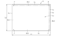
- FIG. 14 shows a rectangular mother glass cut by the method for manufacturing a glass plate according to the present embodiment.
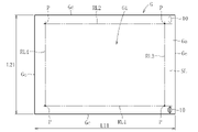
- FIG. 15 shows a rectangular mother glass that is cut by forming a scribe line with a scribe wheel as in the past.
- each of the concave lines RL1 to RL4 is referred to as a first concave line RL1, a second concave line RL2, a third concave line RL3, and a fourth concave line RL4.
- the first concave line RL1 is parallel to the second concave line RL2 and is orthogonal to the third concave line RL3 and the fourth concave line RL4.
- FIG. 15 illustrates a case where an initial crack is formed in the first concave line RL1 and the second concave line RL2.
- the scribe wheel 10 is in contact with the first main surface Ga at a position outside (end surface Gc side) of the third concave line RL3, and is orthogonal to the first concave line RL1 and the second concave line RL2. Move like.
- the depth of cut of the scribe wheel 10 is set so that the scribe wheel 10 reaches the tensile stress layer of the concave line RL.
- a scribe line SL parallel to the third concave line RL3 is formed on the mother glass G.
- This scribe line SL contains a large number of lateral cracks. Therefore, the scribe line SL needs to be formed at a position sufficiently distant from the third concave line RL3 so that the crack starting from this latera crack does not extend to the third concave line RL3. Therefore, in order to form the scribe line SL, the dimensions L11 and L21 of each side of the mother glass G are inevitably large.
- the initial crack formed by the tip-shaped tool 9 includes the lateral crack, but is mainly the relaxation layer, the first base portion 8a and / or the second base portion. It is formed in 8b. Therefore, in the initial crack forming step S2, it is possible to form an initial crack at a position near the intersection P (see FIG. 14) of each concave line RL1 to RL4 which is a corner portion of the glass plate G1.
- the dimensions L1 and L2 of each side of the mother glass G are made smaller when the glass plate G1 having the same dimensions is manufactured as compared with the conventional manufacturing method. It becomes possible. That is, in the present invention, the amount of glass discarded in the cutting step can be reduced as compared with the conventional manufacturing method. Thereby, the yield of the glass plate G1 can be improved.
- the present invention is not limited to the configuration of the above embodiment, and is not limited to the above-mentioned action and effect.
- the present invention can be modified in various ways without departing from the gist of the present invention.
- a concave line including a curved line or a circular concave line may be formed on the mother glass G.
- the initial crack FC is formed by moving the tip-shaped tool 9 from the first base portion 8a to the second base portion 8b of the first protrusion 7a.
- the tool 9 may be brought into contact with the two points of the first protrusion 7a and the second protrusion 7b to form a plurality of initial crack FCs.
- the initial crack FC may be formed by moving the tool 9 from the second base portion 8b of the protrusion 7 toward the first base portion 8a.
- the initial crack FC may be formed only in the first base portion 8a, or the initial crack FC may be formed only in the second base portion 8b. That is, in the initial crack forming step S2, at least one of the first base portion 8a and the second base portion 8b may be scratched. From the viewpoint of improving the production efficiency, it is preferable to scratch at least one of the first base portion 8a and the second base portion 8b.
- the periphery of the first base portion 8a for example, the range from the first base portion 8a to 50 ⁇ m, preferably the range from the first base portion 8a to 30 ⁇ m, more preferably the first base portion 8a).
- a scratch may be formed on the first main surface Ga (range from the base 8a to 20 ⁇ m). From the viewpoint of preventing the formation of scratches on the first main surface Ga, it is preferable to form the initial crack FC only on the first base portion 8a.
- the present method is not limited to this, and the present method is a glass laminate formed by laminating a plurality of mother glasses, or a mother glass and a resin plate. It can also be applied to the case of cutting a glass resin laminate formed by laminating and.
- the second base portion 8b is formed along the width direction Y of the concave line RL.
- the tool 9 was moved toward and vibrated at that time, but the tool 9 does not have to be moved and vibrated.
- Initial crack FC may be formed by contacting the first base portion 8a or the second base portion 8b.
- the kinetic energy when the tip of the tool 9 comes into contact with the first protrusion 7a or the like is preferably 0.013 J or more, for example.
Landscapes
- Engineering & Computer Science (AREA)
- Mechanical Engineering (AREA)
- Chemical & Material Sciences (AREA)
- Materials Engineering (AREA)
- Organic Chemistry (AREA)
- Life Sciences & Earth Sciences (AREA)
- Forests & Forestry (AREA)
- Re-Forming, After-Treatment, Cutting And Transporting Of Glass Products (AREA)
- Processing Of Stones Or Stones Resemblance Materials (AREA)
Abstract
マザーガラスGに形成される凹状線RLは、凹状線RLの幅方向Yの端部RLaに形成される突起部7aを備える。突起部7aは、凹状線RLの幅方向Yの中央部側に位置する第一基部8aと、第一基部8aとは反対側に位置する第二基部8bと、を含む。ガラス板の製造方法における初期クラック形成工程S2では、第一基部8a及び第二基部8bの少なくとも一方に傷を付ける。
Description
本発明は、ガラス板を製造する方法に関する。
液晶ディスプレイ、有機ELディスプレイなどのパネルディスプレイ用のガラス板を製造する場合、例えばダウンドロー法等の成形法により成形された大型のマザーガラスを切断することで、所定の大きさのガラス板を形成する。
特許文献1には、ガラス板の製造方法として、マザーガラスの表面に塑性変形による凹状線を形成する凹状線形成工程と、凹状線に対応する位置に内部初期クラックを形成する初期クラック形成工程と、内部初期クラックを凹状線に沿ってマザーガラスの内部で進展させるクラック進展工程と、マザーガラスを凹状線に沿って折割る折割工程と、を備えたものが開示されている。
この製造方法において、凹状線形成工程により形成された凹状線は、塑性変形によって形成される圧縮応力層と、この圧縮応力層よりもマザーガラスの内部側に形成される引張応力層とを備えている。
初期クラック形成工程では、スクライブホイールをマザーガラスの表面に接触させるとともに、凹状線に交差する方向に移動させる。これにより、マザーガラスには、凹状線と交差するスクライブ線が形成される。このスクライブ線を起点として、引張応力層に内部初期クラックが形成される(同文献の段落0030、0031及び図8参照)。
クラック進展工程では、この内部初期クラックを起点とするクラックを凹状線の引張応力層において進展させる。その後、折割工程を実行することで、端面にラテラルクラックが発生しないガラス板を製造することができる。
上記のように、従来のガラス板の製造方法では、内部初期クラックを形成するために、スクライブホイールによるスクライブ線をマザーガラスに形成している。スクライブ線は、多数のラテラルクラックを含むため、折割工程では、マザーガラスにおいてスクライブ線が形成されている部分をガラス板から分離させ、廃棄する必要がある。
このように、従来のガラス板の製造方法では、マザーガラスにスクライブ線を形成する部分が必要となり、しかも、この部分を廃棄する必要があることから、ガラス板の歩留まりの低下を招いていた。
本発明は上記の事情に鑑みて為されたものであり、切断面にラテラルクラックが発生しないようにマザーガラスを切断するとともに、ガラス板の歩留まりを向上させることを技術的課題とする。
本発明は上記の課題を解決するためのものであり、マザーガラスを切断する切断工程を備えるガラス板の製造方法において、前記切断工程は、前記マザーガラスの表面に塑性変形による凹状線を形成する凹状線形成工程と、前記凹状線に初期クラックを形成する初期クラック形成工程と、前記初期クラックを前記凹状線に沿って前記マザーガラスの内部で進展させるクラック進展工程と、を備え、前記凹状線は、前記凹状線の幅方向の端部に形成される突起部を備え、前記突起部は、前記凹状線の前記幅方向の中央部側に位置する第一基部と、前記第一基部とは反対側に位置する第二基部と、を含み、前記初期クラック形成工程では、前記第一基部及び前記第二基部の少なくとも一方に傷を付けることを特徴とする。
上記の方法によれば、凹状線形成工程において、マザーガラスの表面を塑性変形させることで、ラテラルクラックが存在しない凹状線を形成することができる。初期クラック形成工程では、突起部の第一基部及び第二基部の少なくとも一方に傷を付けることで、突起部に初期クラックを形成することができる。
したがって、本発明では、従来のようにスクライブホイールによって、スクライブ線を凹状線に交差するように形成しなくてもよい。クラック進展工程において、初期クラックを起点とするクラックを凹状線に沿って進展させることにより、端面(切断面)にラテラルクラックを有していないガラス板を製造することができる。
このように、本発明では、凹状線と交差するスクライブ線を形成することなくマザーガラスを切断することができることから、切断工程におけるガラスの廃棄量を可及的に低減することが可能となる。これにより、ガラス板の歩留まりを向上させることができる。
本方法において、前記突起部は、前記凹状線の前記幅方向の一端部に位置する第一突起部と、前記凹状線の前記幅方向の他端部に位置する第二突起部と、を含み、前記初期クラック形成工程では、前記第一突起部又は前記第二突起部に前記傷を付けてもよい。
前記初期クラック形成工程では、前記凹状線の前記幅方向に沿う前記傷を前記突起部に付けてもよい。これにより、突起部に対して初期クラックを容易に形成することができる。
前記初期クラック形成工程では、尖端状の工具を前記第一基部及び前記第二基部の少なくとも一方に接触させることにより前記傷を付けてもよい。これにより、突起部に対して初期クラックを確実に形成することができる。
前記初期クラック形成工程では、前記工具を振動させてもよい。これにより、突起部に対して初期クラックを確実に形成することができる。
本発明によれば、切断面にラテラルクラックが発生しないようにマザーガラスを切断するとともに、ガラス板の歩留まりを向上させることができる。
以下、本発明を実施するための形態について図面を参照しながら説明する。図1乃至図14は、本発明に係るガラス板の製造方法の一実施形態を示す。
図1乃至図3は、本方法においてマザーガラスに凹状線を形成するために使用されるスクライブチップを示す。本実施形態では、ペンシル型のスクライブチップ1を例示するが、スクライブチップの構成は本実施形態に限定されない。スクライブチップ1は、シャンク2と、このシャンク2の端部に固定されるチップ3とを有する。
シャンク2は、金属製であり、円柱状又は多角柱状に構成される。シャンク2は、ホルダHに装着される。ホルダHは、シャンク2を保持するとともに、スクライブチップ1を上下方向及び水平方向に移動させる。また、ホルダHは、マザーガラスGに対するシャンク2の傾斜角度を自在に変更できる。
チップ3は、例えば単結晶又は多結晶のダイヤモンドチップからなるが、これに限定されず、PCBN、セラミック、又は超硬合金その他の金属により構成され得る。チップ3は、接着剤、ろう材等によりシャンク2の先端部に固定されている。チップ3は、切頭円錐台状に構成されており、その端部には、マザーガラスGに接触する押圧部4が形成されている。すなわち、チップ3の軸方向の端面3aにおける縁部が押圧部4となっている。
押圧部4は、マザーガラスGにラテラルクラックを発生させないように、円弧状に構成される。押圧部4は、マザーガラスGの表面を押圧することにより塑性変形させ、この塑性変形部に凹状線RLを形成する。押圧部4の半径(曲率半径)は、0.001mm~1mmとされることが好ましく、0.025mm~0.5mmとされることがより好ましい。
この円形の押圧部4は、複数の円弧から成るものと見做すことができる。例えば図2に示すように、押圧部4は、三個の円弧4a~4cにより仮想的に構成される。この例において、各円弧4a~4cの中心角θaは、120°に設定されているが、これに限らず、5°~120°とされることが望ましい。なお、各円弧4a~4cの中心角θaは等しく設定しているが、これらを異なる角度で構成してもよい。
本方法に使用されるマザーガラスGは、図3に示すように、表裏の関係にある第一主面Gaおよび第二主面Gbと、第一主面Gaと第二主面Gbとを繋ぐ端面Gcとを備える。本発明において、第一主面Ga又は第二主面Gbの少なくとも一方をマザーガラスGの「表面」という。本実施形態では、マザーガラスGの厚みtは、0.01mm~1mmとされることが好ましく、より好ましくは、0.01mm~0.7mmである。マザーガラスGは、一辺の長さが1000mm以上の大きさを有するが、この寸法に限定されるものではない。
マザーガラスGは、公知のフロート法、ロールアウト法、スロットダウンドロー法、リドロー法等の各種成形法により成形され得るが、オーバーフローダウンドロー法により成形されることが好ましい。オーバーフローダウンドロー法は、断面が略くさび形の成形体の上部に設けられたオーバーフロー溝に溶融ガラスを流し込み、このオーバーフロー溝から両側に溢れ出た溶融ガラスを成形体の両側の側壁部に沿って流下させながら、成形体の下端部で融合一体化し、一枚の帯状ガラスを連続成形するというものである。帯状ガラスの一部を幅方向に切断することで、矩形状のマザーガラスGが形成される。
以下、ガラス板の製造方法について説明する。この例では、無アルカリガラス(日本電気硝子株式会社製OA-10G)からなる矩形のマザーガラスGから矩形のガラス板を製造する場合について説明する。
本方法は、マザーガラスGを切断する切断工程を備える。図4に示すように、切断工程は、スクライブチップ1によりマザーガラスGの表面(例えば第一主面Ga)に塑性変形による凹状線RLを形成する凹状線形成工程S1と、凹状線RLに初期クラックを形成する初期クラック形成工程S2と、初期クラックを凹状線RLに沿ってマザーガラスGの内部に進展させるクラック進展工程S3と、マザーガラスGに曲げ応力を作用させる折割工程S4と、を備える。
凹状線形成工程S1では、まず、載置台(図示せず)にマザーガラスGを載置し、このマザーガラスGの第一主面Gaに、スクライブチップ1を接触させる。なお、載置台には、樹脂シートが載置され、マザーガラスGは、この樹脂シートに載置されることが望ましい。スクライブチップ1は、シャンク2がマザーガラスGに対して傾斜するようにホルダHに支持される。シャンク2を移動方向X側に傾斜させる場合、その傾斜角度θb(図3参照)は、30°~85°とされることが望ましいが、この範囲に限定されるものではない。
その後、スクライブチップ1に荷重を付与し、チップ3の押圧部4によってマザーガラスGの第一主面Gaを押圧しつつ、図5に示すように移動方向Xに沿って摺動させる。スクライブチップ1の移動速度は、50mm/s~1500mm/sとされることが望ましい。スクライブチップ1に付与される荷重は、0.1N~10Nとされるが、この範囲に限定されず、マザーガラスGの大きさ、厚み、材質等の条件に応じて適宜設定される。なお、押圧部4(円弧4aの部分)は、この移動方向Xに対して直交する向き(円弧4aに係る接線と移動方向Xとが直交するように)に配置される(図2参照)。
第一主面Gaの一部は、押圧部4の押圧により塑性変形する。図5に示すように、押圧部4の移動によって、第一主面Gaにおける塑性変形部分に直線状の凹状線RLが形成される。以下、凹状線RLの長手方向(移動方向X)に直交する方向を、凹状線RLの幅方向Yという。凹状線RLの幅方向Yに係る幅寸法W1(図6参照)は、10μm~50μmとされることが望ましい。凹状線RLの深さは、0.3μm~1.0μmとされることが望ましい。
図6に示すように、凹状線RLは、圧縮応力層5と、引張応力層6と、突起部7a,7bと、を含む。
圧縮応力層5は、マザーガラスGの第一主面Gaが塑性変形することにより構成される。引張応力層6は、圧縮応力層5よりもマザーガラスGの内部側に形成される。引張応力層6は、圧縮応力層5によって覆われている。
突起部7a,7bは、凹状線RLの幅方向Yにおける端部RLa,RLbに形成される。突起部7a,7bは、マザーガラスGが塑性変形することにより、第一主面Gaから突出している。この突起部7a,7bの突出量(第一主面Gaからの高さ)hは、0.01μm~0.10μmとされることが望ましい。突起部7a,7bは、凹状線RLの全長に亘って形成される。突起部7a,7bは、圧縮応力層5の一部5aと、引張応力層6の一部6aとを含む。
突起部7a,7bは、凹状線RLの幅方向Yの一端部RLaに形成される第一突起部7aと、凹状線RLの幅方向Yの他端部RLbに形成される第二突起部7bと、を含む。各突起部7a,7bは、凹状線RLの幅方向Yの中央部(底部)側に位置する第一基部8aと、幅方向Yにおいて第一基部8aとは反対側に位置する第二基部8bと、を含む。凹状線RLの幅方向Yにおける各突起部7a,7bの幅寸法W2(第一基部8aから第二基部8bまでの距離)は、2μm~10μmとされることが好ましい。
図7に示すように、第一基部8a及び第二基部8bは、圧縮応力が緩和された緩和層である。この緩和層には、僅かな圧縮応力又は引張応力が作用しているか、圧縮応力及び引張応力がほぼ相殺されていると推察される。この緩和層である第一基部8a及び第二基部8bの幅寸法W3は、すなわち、傷を付けることが可能な第一基部8a及び第二基部8bの幅寸法は、例えば1μm以下である。
図8に示すように、初期クラック形成工程S2では、突起部7a,7bの位置における引張応力層6aに初期クラックを形成するように、尖端状の工具9によって突起部7a,7bに傷を付ける。尖端状の工具9としては、例えばダイヤモンドチップや超硬工具を用いることができる。より具体的には、電着系のダイヤモンドヤスリや超硬製のケガキ工具を用いることができる。
本実施形態では、第一突起部7aのみに傷を付ける例を示すが、これに限らず、第二突起部7bのみ、或いは第一突起部7a及び第二突起部7bの両方に傷を付けてもよい。
具体的には、初期クラック形成工程S2では、工具9の先端部を第一突起部7aの第一基部8aに接触させた後、凹状線RLの幅方向Yに沿って、第二基部8bに向かって移動させる。この場合において、工具9をその軸心回りに回転させてもよく、工具9を振動させてもよい。初期クラックを確実に形成する観点では、工具9を振動させることが好ましい。この場合、例えば振幅が10μm~15μmで、振動数が100Hz~300Hzで振動する工具9を第一基部8a及び第二基部8bにそれぞれ数回~数百回接触させればよい。
このような工具9の移動によって、第一突起部7aに傷が形成される。この傷は、第一突起部7aの緩和層である第一基部8a及び第二基部8bに形成され、第一基部8aと第二基部8bとの間における圧縮応力層5aには形成されない。以下、第一突起部7aの緩和層である第一基部8a及び第二基部8bに形成された傷を、初期クラックFCという。
クラック進展工程S3では、初期クラックFCを起点として、引張応力層6内においてクラックが進展することとなる。第二基部8bの初期クラックFCは、図9及び図10において矢印A1で示すように、引張応力層6に残留する応力の作用により、凹状線RLの幅方向Yに沿って進展して第一突起部7aを横断し、第一基部8aに到達する。第一基部8aに到達したクラック又は第一基部8aの初期クラックFCは、図9及び図10において矢印A2で示すように、引張応力層6に残留する応力の作用により、圧縮応力層5aに沿って凹状線RLの幅方向Yの中央部(底部)に向かって進展する。
クラックは、凹状線RLの底部に対応する位置まで到達すると、図9及び図11において矢印A3で示すように、凹状線RLの長手方向に沿って進展する。図10及び図11において、凹状線RLの底部に対応する位置に到達したクラックを符号Cで示す(図12において同じ)。
クラック進展工程S3において、クラックCの進展速度を向上させるために、マザーガラスGに外力F1(図11参照)を付与してもよい。この外力F1により、マザーガラスGには、凹状線RLを跨ぐように曲げ応力が発生し、クラックCは、より高速でマザーガラスGの内部を進展する。外力F1は、クラックCがマザーガラスGの厚さ方向に進展しないように調整される。
クラックCが凹状線RLに沿って進展し終わると、折割工程S4が実行される。図12に示すように、折割工程S4では、クラックCをマザーガラスGの厚さ方向に進展させるべく、マザーガラスGに外力F2を付与する。
この外力F2は、クラック進展工程S3においてマザーガラスGに付与される外力F1よりも大きく設定される。外力F2により、マザーガラスGには、凹状線RLを跨ぐように曲げ応力が発生する。
クラックCは、この曲げ応力の作用により、マザーガラスGの厚さ方向に進展する。クラックCが第一主面Ga及び第二主面Gbに到達すると、マザーガラスGは分断される。これにより、ガラス板G1が形成される。
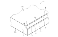
図13に示すように、ガラス板G1は、第一主面G1aと、第一主面G1aの反対側に位置する第二主面G1bと、第一主面G1aと第二主面G1bとを繋ぐ端面G1cとを有する。さらにガラス板G1は、第一主面G1aと端面G1cとの境界部Bに、凹状線RLの痕跡である湾曲面CS及び突起部7(第一突起部7a又は第二突起部7b)を有する。湾曲面CSと突起部7には、ラテラルクラックが存在しないため、ガラス板G1は、研削加工を施さずとも機械的強度の高いものとなる。加えて、ガラス板G1には、湾曲面CSに沿って形成される圧縮応力層5と、この圧縮応力層5よりも内部側に位置する引張応力層6とが残存する。
以下、図14及び図15を参照しながら、本実施形態に係るガラス板G1の製造方法による歩留まり向上の効果について説明する。図14は、本実施形態によるガラス板の製造方法により切断される矩形状のマザーガラスを示す。図15は、従来のようにスクライブホイールによってスクライブ線を形成することにより切断される矩形状のマザーガラスを示す。
図14及び図15に示す例では、凹状線形成工程S1によって、マザーガラスGの四辺の端面Gcよりも内側の位置で第一主面Gaに四本の凹状線RL1~RL4が形成される。以下、凹状線RL1~RL4のそれぞれを、第一凹状線RL1、第二凹状線RL2、第三凹状線RL3及び第四凹状線RL4という。第一凹状線RL1は、第二凹状線RL2と平行であり、第三凹状線RL3及び第四凹状線RL4と直交している。
図15では、第一凹状線RL1及び第二凹状線RL2に対して初期クラックを形成する場合を例示する。この場合において、スクライブホイール10は、第三凹状線RL3よりも外側(端面Gc側)の位置で第一主面Gaに接触しており、第一凹状線RL1及び第二凹状線RL2と直交するように移動する。スクライブホイール10の切り込み量は、スクライブホイール10が凹状線RLの引張応力層に達するように設定されている。
スクライブホイール10の移動により、マザーガラスGには、第三凹状線RL3と平行なスクライブ線SLが形成される。このスクライブ線SLは、多数のラテラルクラックを含んでいる。このため、スクライブ線SLは、このラテラクラックを起点としたクラックが第三凹状線RL3に進展しないように、第三凹状線RL3から十分に離れた位置に形成する必要がある。したがって、スクライブ線SLを形成するために、マザーガラスGの各辺の寸法L11,L21は、必然的に大きくなる。
これに対し、本実施形態における初期クラック形成工程S2において、尖端状の工具9によって形成される初期クラックは、ラテラルクラックを含むが、主に緩和層である第一基部8a及び/又は第二基部8bに形成される。このため、初期クラック形成工程S2では、ガラス板G1の角部となる各凹状線RL1~RL4の交点P(図14参照)の近傍位置で初期クラックを形成することが可能となる。
したがって、本実施形態に係るガラス板G1の製造方法では、従来の製造方法と比較して、同じ寸法のガラス板G1を製造する場合に、マザーガラスGの各辺の寸法L1,L2を小さくすることが可能となる。すなわち、本発明では、従来の製造方法と比較して、切断工程において廃棄されるガラスの量を低減することができる。これにより、ガラス板G1の歩留まりを向上させることができる。
なお、本発明は、上記実施形態の構成に限定されるものではなく、上記した作用効果に限定されるものでもない。本発明は、本発明の要旨を逸脱しない範囲で種々の変更が可能である。
上記の実施形態では、凹状線形成工程S1において、直線状の凹状線RLをマザーガラスGに形成する例を示したが、本発明はこの態様に限定されるものではない。凹状線形成工程S1では、曲線を含む凹状線や円形の凹状線をマザーガラスGに形成してもよい。
上記の実施形態では、初期クラック形成工程S2において、尖端状の工具9を第一突起部7aの第一基部8aから第二基部8bまで移動させることにより、初期クラックFCを形成したが、本発明はこの態様に限定されない。図16に示すように、初期クラック形成工程S2において、第一突起部7aと第二突起部7bの二箇所に工具9を接触させ、複数の初期クラックFCを形成してもよい。また、工具9を突起部7の第二基部8bから第一基部8aに向かって移動させることで、初期クラックFCを形成してもよい。
また、初期クラック形成工程S2では、第一基部8aのみに初期クラックFCを形成してもよく、第二基部8bのみに初期クラックFCを形成してもよい。すなわち、初期クラック形成工程S2では、第一基部8a及び第二基部8bの少なくとも一方に傷を付ければよい。製造効率を向上させる観点では、第一基部8a及び第二基部8bの少なくとも一方に傷を付けることが好ましい。なお、第一基部8aのみに初期クラックFCを形成する際に、第一基部8aの周辺(例えば第一基部8aから50μmの範囲、好ましくは第一基部8aから30μmの範囲、より好ましくは第一基部8aから20μmの範囲)の第一主面Gaに傷が形成されてもよい。この第一主面Gaに傷が形成されることを防止する観点では、第一基部8aのみに初期クラックFCを形成することが好ましい。
上記の実施形態では、単層のマザーガラスGを切断する例を示したが、これに限定されず、本方法は、複数のマザーガラスを積層してなるガラス積層体、又はマザーガラスと樹脂板とを積層してなるガラス樹脂積層体を切断する場合にも適用可能である。
上記の実施形態の初期クラック形成工程S2では、工具9の先端部を第一突起部7aの第一基部8aに接触させた後、凹状線RLの幅方向Yに沿って、第二基部8bに向かって移動させ、その際に工具9を振動させたが、工具9を移動及び振動させなくてもよい。例えば、工具9の先端部を第一突起部7aの第一基部8a又は第二基部8bの上方に配置した状態で、その工具9を落下させて工具9の先端部を第一突起部7aの第一基部8a又は第二基部8bに接触させることにより、初期クラックFCを形成してもよい。この場合、工具9の先端部が第一突起部7a等に接触する際の運動エネルギーは、例えば0.013J以上であることが好ましい。
7a 第一突起部
7b 第二突起部
8a 第一基部
8b 第二基部
9 尖端状の工具
FC 初期クラック
G マザーガラス
G1 ガラス板
RLa 凹状線の幅方向の端部
RLb 凹状線の幅方向の端部
S1 凹状線形成工程
S2 初期クラック形成工程
S3 クラック進展工程
Y 凹状線の幅方向
7b 第二突起部
8a 第一基部
8b 第二基部
9 尖端状の工具
FC 初期クラック
G マザーガラス
G1 ガラス板
RLa 凹状線の幅方向の端部
RLb 凹状線の幅方向の端部
S1 凹状線形成工程
S2 初期クラック形成工程
S3 クラック進展工程
Y 凹状線の幅方向
Claims (5)
- マザーガラスを切断する切断工程を備えるガラス板の製造方法において、
前記切断工程は、前記マザーガラスの表面に塑性変形による凹状線を形成する凹状線形成工程と、前記凹状線に初期クラックを形成する初期クラック形成工程と、前記初期クラックを前記凹状線に沿って前記マザーガラスの内部で進展させるクラック進展工程と、を備え、
前記凹状線は、前記凹状線の幅方向の端部に形成される突起部を備え、
前記突起部は、前記凹状線の前記幅方向の中央部側に位置する第一基部と、前記第一基部とは反対側に位置する第二基部と、を含み、
前記初期クラック形成工程では、前記第一基部及び前記第二基部の少なくとも一方に傷を付けることを特徴とするガラス板の製造方法。 - 前記突起部は、前記凹状線の前記幅方向の一端部に位置する第一突起部と、前記凹状線の前記幅方向の他端部に位置する第二突起部と、を含み、
前記初期クラック形成工程では、前記第一突起部又は前記第二突起部に前記傷を付ける請求項1に記載のガラス板の製造方法。 - 前記初期クラック形成工程では、前記凹状線の前記幅方向に沿う前記傷を前記突起部に付ける請求項1又は2に記載のガラス板の製造方法。
- 前記初期クラック形成工程では、尖端状の工具を前記第一基部及び前記第二基部の少なくとも一方に接触させることにより前記傷を付ける請求項1から3のいずれか一項に記載のガラス板の製造方法。
- 前記初期クラック形成工程では、前記工具を振動させる請求項4に記載のガラス板の製造方法。
Priority Applications (1)
| Application Number | Priority Date | Filing Date | Title |
|---|---|---|---|
| JP2022557303A JP7730460B2 (ja) | 2020-10-19 | 2021-09-21 | ガラス板の製造方法 |
Applications Claiming Priority (2)
| Application Number | Priority Date | Filing Date | Title |
|---|---|---|---|
| JP2020175371 | 2020-10-19 | ||
| JP2020-175371 | 2020-10-19 |
Publications (1)
| Publication Number | Publication Date |
|---|---|
| WO2022085347A1 true WO2022085347A1 (ja) | 2022-04-28 |
Family
ID=81289775
Family Applications (1)
| Application Number | Title | Priority Date | Filing Date |
|---|---|---|---|
| PCT/JP2021/034549 Ceased WO2022085347A1 (ja) | 2020-10-19 | 2021-09-21 | ガラス板の製造方法 |
Country Status (3)
| Country | Link |
|---|---|
| JP (1) | JP7730460B2 (ja) |
| TW (1) | TW202216620A (ja) |
| WO (1) | WO2022085347A1 (ja) |
Citations (3)
| Publication number | Priority date | Publication date | Assignee | Title |
|---|---|---|---|---|
| JP2019089672A (ja) * | 2017-11-14 | 2019-06-13 | 日本電気硝子株式会社 | ガラス板の製造方法及びガラス板 |
| JP2019112294A (ja) * | 2017-12-21 | 2019-07-11 | 日本電気硝子株式会社 | ガラス基板の製造方法 |
| JP2020097496A (ja) * | 2018-12-17 | 2020-06-25 | 日本電気硝子株式会社 | スクライブ装置及びガラス基板の製造方法 |
Family Cites Families (4)
| Publication number | Priority date | Publication date | Assignee | Title |
|---|---|---|---|---|
| JPH04249113A (ja) * | 1991-02-06 | 1992-09-04 | Mitsubishi Electric Corp | ウエハスクライバ |
| JP4203177B2 (ja) | 1999-03-18 | 2008-12-24 | 株式会社ベルデックス | スクライブ方法および装置 |
| JP2010254538A (ja) | 2009-04-28 | 2010-11-11 | Sharp Corp | 分断装置 |
| JP5779074B2 (ja) | 2011-11-02 | 2015-09-16 | 三星ダイヤモンド工業株式会社 | 強化ガラス基板のスクライブ方法 |
-
2021
- 2021-09-21 JP JP2022557303A patent/JP7730460B2/ja active Active
- 2021-09-21 WO PCT/JP2021/034549 patent/WO2022085347A1/ja not_active Ceased
- 2021-09-24 TW TW110135644A patent/TW202216620A/zh unknown
Patent Citations (3)
| Publication number | Priority date | Publication date | Assignee | Title |
|---|---|---|---|---|
| JP2019089672A (ja) * | 2017-11-14 | 2019-06-13 | 日本電気硝子株式会社 | ガラス板の製造方法及びガラス板 |
| JP2019112294A (ja) * | 2017-12-21 | 2019-07-11 | 日本電気硝子株式会社 | ガラス基板の製造方法 |
| JP2020097496A (ja) * | 2018-12-17 | 2020-06-25 | 日本電気硝子株式会社 | スクライブ装置及びガラス基板の製造方法 |
Also Published As
| Publication number | Publication date |
|---|---|
| JP7730460B2 (ja) | 2025-08-28 |
| TW202216620A (zh) | 2022-05-01 |
| JPWO2022085347A1 (ja) | 2022-04-28 |
Similar Documents
| Publication | Publication Date | Title |
|---|---|---|
| KR20000023191A (ko) | 판유리 모재의 절단 방법 및 그 장치 | |
| JP6032428B2 (ja) | ガラスフィルム切断装置及びガラスフィルム切断方法 | |
| JP6911720B2 (ja) | ガラス板の製造方法及びガラス板 | |
| KR102719803B1 (ko) | 컷팅 에지를 갖는 유리 부재 및 이의 제조 방법 | |
| JP5156080B2 (ja) | 貼り合せ基板のスクライブ方法 | |
| TW201821284A (zh) | 玻璃樹脂積層體的製造方法及玻璃樹脂積層體 | |
| KR102708326B1 (ko) | 유리판의 제조 방법 | |
| JP7730460B2 (ja) | ガラス板の製造方法 | |
| JP7800791B2 (ja) | 板ガラスの製造方法、板ガラスの製造装置、及び板ガラス | |
| JP2019112294A (ja) | ガラス基板の製造方法 | |
| JP6555354B2 (ja) | 脆性基板の分断方法 | |
| CN106660853A (zh) | 无碱玻璃板的切割方法、显示面板的切割方法、无碱玻璃板的制造方法、以及显示面板的制造方法 | |
| JP4890034B2 (ja) | 光学部品の製造方法 | |
| CN107127899A (zh) | 脆性基板的分割方法 | |
| TW201714720A (zh) | 脆性材料基板之分斷方法 | |
| WO2023120246A1 (ja) | 積層体の製造方法 | |
| CN107848862B (zh) | 脆性基板的分断方法 | |
| US20210269351A1 (en) | Handheld sheet edge strip separation devices and methods of separating glass sheets | |
| US12630457B2 (en) | Glass element with cut edge and method of producing same | |
| CN108698254B (zh) | 脆性衬底的分断方法 | |
| JP4998203B2 (ja) | 半導体装置の製造方法 | |
| CN119233952A (zh) | 玻璃板的制造方法以及刻划装置 | |
| JP2009143764A (ja) | ガラス基板の加工方法 | |
| TW202423864A (zh) | 玻璃物品的製造方法、及玻璃物品的製造裝置 | |
| KR20220092425A (ko) | 취성 재료 기판의 가공 방법 및 분단 방법 |
Legal Events
| Date | Code | Title | Description |
|---|---|---|---|
| 121 | Ep: the epo has been informed by wipo that ep was designated in this application |
Ref document number: 21882488 Country of ref document: EP Kind code of ref document: A1 |
|
| ENP | Entry into the national phase |
Ref document number: 2022557303 Country of ref document: JP Kind code of ref document: A |
|
| NENP | Non-entry into the national phase |
Ref country code: DE |
|
| 122 | Ep: pct application non-entry in european phase |
Ref document number: 21882488 Country of ref document: EP Kind code of ref document: A1 |