WO2022085254A1 - 通信装置及び通信方法 - Google Patents
通信装置及び通信方法 Download PDFInfo
- Publication number
- WO2022085254A1 WO2022085254A1 PCT/JP2021/026327 JP2021026327W WO2022085254A1 WO 2022085254 A1 WO2022085254 A1 WO 2022085254A1 JP 2021026327 W JP2021026327 W JP 2021026327W WO 2022085254 A1 WO2022085254 A1 WO 2022085254A1
- Authority
- WO
- WIPO (PCT)
- Prior art keywords
- data
- transmission
- data size
- communication device
- terminal
- Prior art date
Links
- 238000000034 method Methods 0.000 title claims description 118
- 238000004891 communication Methods 0.000 title claims description 105
- 230000005540 biological transmission Effects 0.000 claims abstract description 215
- 230000008569 process Effects 0.000 claims description 54
- 238000013468 resource allocation Methods 0.000 claims description 8
- 230000004044 response Effects 0.000 claims description 4
- 101000741965 Homo sapiens Inactive tyrosine-protein kinase PRAG1 Proteins 0.000 description 52
- 102100038659 Inactive tyrosine-protein kinase PRAG1 Human genes 0.000 description 52
- 230000006870 function Effects 0.000 description 40
- 238000012545 processing Methods 0.000 description 35
- 238000004364 calculation method Methods 0.000 description 19
- 238000010586 diagram Methods 0.000 description 19
- 238000013507 mapping Methods 0.000 description 17
- 238000007726 management method Methods 0.000 description 13
- 230000011664 signaling Effects 0.000 description 12
- 238000005516 engineering process Methods 0.000 description 11
- 238000006243 chemical reaction Methods 0.000 description 8
- 238000012937 correction Methods 0.000 description 7
- 230000002829 reductive effect Effects 0.000 description 7
- 230000006872 improvement Effects 0.000 description 4
- 230000007246 mechanism Effects 0.000 description 3
- 230000003252 repetitive effect Effects 0.000 description 3
- 238000000926 separation method Methods 0.000 description 3
- 230000003595 spectral effect Effects 0.000 description 3
- 102100022734 Acyl carrier protein, mitochondrial Human genes 0.000 description 2
- 101000678845 Homo sapiens Acyl carrier protein, mitochondrial Proteins 0.000 description 2
- 101100437508 Rhizobium radiobacter cbg-1 gene Proteins 0.000 description 2
- 230000002776 aggregation Effects 0.000 description 2
- 238000004220 aggregation Methods 0.000 description 2
- 230000003321 amplification Effects 0.000 description 2
- 230000008901 benefit Effects 0.000 description 2
- 230000003139 buffering effect Effects 0.000 description 2
- 230000001413 cellular effect Effects 0.000 description 2
- 238000004590 computer program Methods 0.000 description 2
- 125000004122 cyclic group Chemical group 0.000 description 2
- 230000001934 delay Effects 0.000 description 2
- 238000009826 distribution Methods 0.000 description 2
- 230000000694 effects Effects 0.000 description 2
- 101150091511 glb-1 gene Proteins 0.000 description 2
- 230000000670 limiting effect Effects 0.000 description 2
- 238000004519 manufacturing process Methods 0.000 description 2
- 238000005259 measurement Methods 0.000 description 2
- 238000003199 nucleic acid amplification method Methods 0.000 description 2
- 230000036961 partial effect Effects 0.000 description 2
- 230000007704 transition Effects 0.000 description 2
- NAWXUBYGYWOOIX-SFHVURJKSA-N (2s)-2-[[4-[2-(2,4-diaminoquinazolin-6-yl)ethyl]benzoyl]amino]-4-methylidenepentanedioic acid Chemical compound C1=CC2=NC(N)=NC(N)=C2C=C1CCC1=CC=C(C(=O)N[C@@H](CC(=C)C(O)=O)C(O)=O)C=C1 NAWXUBYGYWOOIX-SFHVURJKSA-N 0.000 description 1
- 101100150274 Caenorhabditis elegans srb-2 gene Proteins 0.000 description 1
- 241000854291 Dianthus carthusianorum Species 0.000 description 1
- 101001055444 Homo sapiens Mediator of RNA polymerase II transcription subunit 20 Proteins 0.000 description 1
- 102100026165 Mediator of RNA polymerase II transcription subunit 20 Human genes 0.000 description 1
- 230000006978 adaptation Effects 0.000 description 1
- 230000002411 adverse Effects 0.000 description 1
- 230000003190 augmentative effect Effects 0.000 description 1
- 230000015572 biosynthetic process Effects 0.000 description 1
- 230000008859 change Effects 0.000 description 1
- 238000007906 compression Methods 0.000 description 1
- 230000006835 compression Effects 0.000 description 1
- 238000013523 data management Methods 0.000 description 1
- 230000006866 deterioration Effects 0.000 description 1
- 238000011161 development Methods 0.000 description 1
- 239000003814 drug Substances 0.000 description 1
- 238000005538 encapsulation Methods 0.000 description 1
- 238000001914 filtration Methods 0.000 description 1
- 238000009472 formulation Methods 0.000 description 1
- 230000036541 health Effects 0.000 description 1
- 238000009776 industrial production Methods 0.000 description 1
- 238000007689 inspection Methods 0.000 description 1
- 230000010354 integration Effects 0.000 description 1
- 230000003993 interaction Effects 0.000 description 1
- 230000007774 longterm Effects 0.000 description 1
- 238000012423 maintenance Methods 0.000 description 1
- 230000014759 maintenance of location Effects 0.000 description 1
- 239000000203 mixture Substances 0.000 description 1
- 230000004048 modification Effects 0.000 description 1
- 238000012986 modification Methods 0.000 description 1
- 238000012544 monitoring process Methods 0.000 description 1
- 230000010363 phase shift Effects 0.000 description 1
- 230000001172 regenerating effect Effects 0.000 description 1
- 230000000717 retained effect Effects 0.000 description 1
- 239000004065 semiconductor Substances 0.000 description 1
- 238000003860 storage Methods 0.000 description 1
- 238000001356 surgical procedure Methods 0.000 description 1
- 230000002194 synthesizing effect Effects 0.000 description 1
- 238000012384 transportation and delivery Methods 0.000 description 1
- 238000011144 upstream manufacturing Methods 0.000 description 1
- 238000012795 verification Methods 0.000 description 1
Images


Classifications
-
- H—ELECTRICITY
- H04—ELECTRIC COMMUNICATION TECHNIQUE
- H04L—TRANSMISSION OF DIGITAL INFORMATION, e.g. TELEGRAPHIC COMMUNICATION
- H04L5/00—Arrangements affording multiple use of the transmission path
- H04L5/003—Arrangements for allocating sub-channels of the transmission path
- H04L5/0044—Arrangements for allocating sub-channels of the transmission path allocation of payload
- H04L5/0046—Determination of how many bits are transmitted on different sub-channels
-
- H—ELECTRICITY
- H04—ELECTRIC COMMUNICATION TECHNIQUE
- H04W—WIRELESS COMMUNICATION NETWORKS
- H04W72/00—Local resource management
- H04W72/04—Wireless resource allocation
- H04W72/044—Wireless resource allocation based on the type of the allocated resource
- H04W72/0446—Resources in time domain, e.g. slots or frames
-
- H—ELECTRICITY
- H04—ELECTRIC COMMUNICATION TECHNIQUE
- H04L—TRANSMISSION OF DIGITAL INFORMATION, e.g. TELEGRAPHIC COMMUNICATION
- H04L1/00—Arrangements for detecting or preventing errors in the information received
- H04L1/08—Arrangements for detecting or preventing errors in the information received by repeating transmission, e.g. Verdan system
-
- H—ELECTRICITY
- H04—ELECTRIC COMMUNICATION TECHNIQUE
- H04L—TRANSMISSION OF DIGITAL INFORMATION, e.g. TELEGRAPHIC COMMUNICATION
- H04L1/00—Arrangements for detecting or preventing errors in the information received
- H04L1/12—Arrangements for detecting or preventing errors in the information received by using return channel
- H04L1/16—Arrangements for detecting or preventing errors in the information received by using return channel in which the return channel carries supervisory signals, e.g. repetition request signals
- H04L1/1607—Details of the supervisory signal
- H04L1/1614—Details of the supervisory signal using bitmaps
-
- H—ELECTRICITY
- H04—ELECTRIC COMMUNICATION TECHNIQUE
- H04L—TRANSMISSION OF DIGITAL INFORMATION, e.g. TELEGRAPHIC COMMUNICATION
- H04L1/00—Arrangements for detecting or preventing errors in the information received
- H04L1/12—Arrangements for detecting or preventing errors in the information received by using return channel
- H04L1/16—Arrangements for detecting or preventing errors in the information received by using return channel in which the return channel carries supervisory signals, e.g. repetition request signals
- H04L1/18—Automatic repetition systems, e.g. Van Duuren systems
- H04L1/1829—Arrangements specially adapted for the receiver end
- H04L1/1861—Physical mapping arrangements
-
- H—ELECTRICITY
- H04—ELECTRIC COMMUNICATION TECHNIQUE
- H04L—TRANSMISSION OF DIGITAL INFORMATION, e.g. TELEGRAPHIC COMMUNICATION
- H04L1/00—Arrangements for detecting or preventing errors in the information received
- H04L1/12—Arrangements for detecting or preventing errors in the information received by using return channel
- H04L1/16—Arrangements for detecting or preventing errors in the information received by using return channel in which the return channel carries supervisory signals, e.g. repetition request signals
- H04L1/18—Automatic repetition systems, e.g. Van Duuren systems
- H04L1/1829—Arrangements specially adapted for the receiver end
- H04L1/1864—ARQ related signaling
-
- H—ELECTRICITY
- H04—ELECTRIC COMMUNICATION TECHNIQUE
- H04L—TRANSMISSION OF DIGITAL INFORMATION, e.g. TELEGRAPHIC COMMUNICATION
- H04L1/00—Arrangements for detecting or preventing errors in the information received
- H04L1/12—Arrangements for detecting or preventing errors in the information received by using return channel
- H04L1/16—Arrangements for detecting or preventing errors in the information received by using return channel in which the return channel carries supervisory signals, e.g. repetition request signals
- H04L1/18—Automatic repetition systems, e.g. Van Duuren systems
- H04L1/1867—Arrangements specially adapted for the transmitter end
- H04L1/1893—Physical mapping arrangements
-
- H—ELECTRICITY
- H04—ELECTRIC COMMUNICATION TECHNIQUE
- H04L—TRANSMISSION OF DIGITAL INFORMATION, e.g. TELEGRAPHIC COMMUNICATION
- H04L1/00—Arrangements for detecting or preventing errors in the information received
- H04L1/12—Arrangements for detecting or preventing errors in the information received by using return channel
- H04L1/16—Arrangements for detecting or preventing errors in the information received by using return channel in which the return channel carries supervisory signals, e.g. repetition request signals
- H04L1/18—Automatic repetition systems, e.g. Van Duuren systems
- H04L1/1867—Arrangements specially adapted for the transmitter end
- H04L1/1896—ARQ related signaling
-
- H—ELECTRICITY
- H04—ELECTRIC COMMUNICATION TECHNIQUE
- H04L—TRANSMISSION OF DIGITAL INFORMATION, e.g. TELEGRAPHIC COMMUNICATION
- H04L27/00—Modulated-carrier systems
- H04L27/26—Systems using multi-frequency codes
- H04L27/2601—Multicarrier modulation systems
- H04L27/2602—Signal structure
-
- H—ELECTRICITY
- H04—ELECTRIC COMMUNICATION TECHNIQUE
- H04B—TRANSMISSION
- H04B7/00—Radio transmission systems, i.e. using radiation field
- H04B7/14—Relay systems
- H04B7/15—Active relay systems
- H04B7/185—Space-based or airborne stations; Stations for satellite systems
- H04B7/1851—Systems using a satellite or space-based relay
- H04B7/18513—Transmission in a satellite or space-based system
-
- H—ELECTRICITY
- H04—ELECTRIC COMMUNICATION TECHNIQUE
- H04L—TRANSMISSION OF DIGITAL INFORMATION, e.g. TELEGRAPHIC COMMUNICATION
- H04L1/00—Arrangements for detecting or preventing errors in the information received
- H04L1/004—Arrangements for detecting or preventing errors in the information received by using forward error control
- H04L1/0056—Systems characterized by the type of code used
- H04L1/0057—Block codes
-
- H—ELECTRICITY
- H04—ELECTRIC COMMUNICATION TECHNIQUE
- H04L—TRANSMISSION OF DIGITAL INFORMATION, e.g. TELEGRAPHIC COMMUNICATION
- H04L5/00—Arrangements affording multiple use of the transmission path
- H04L5/003—Arrangements for allocating sub-channels of the transmission path
- H04L5/0048—Allocation of pilot signals, i.e. of signals known to the receiver
- H04L5/0051—Allocation of pilot signals, i.e. of signals known to the receiver of dedicated pilots, i.e. pilots destined for a single user or terminal
-
- H—ELECTRICITY
- H04—ELECTRIC COMMUNICATION TECHNIQUE
- H04L—TRANSMISSION OF DIGITAL INFORMATION, e.g. TELEGRAPHIC COMMUNICATION
- H04L5/00—Arrangements affording multiple use of the transmission path
- H04L5/003—Arrangements for allocating sub-channels of the transmission path
- H04L5/0053—Allocation of signaling, i.e. of overhead other than pilot signals
- H04L5/0055—Physical resource allocation for ACK/NACK
Definitions
- This disclosure relates to communication devices and communication methods.
- NR New Radio access technology
- the non-limiting examples of the present disclosure contribute to the provision of a communication device and a communication method capable of improving the throughput in wireless communication.
- the communication device includes a control circuit for determining a data size based on information regarding the number of repetitions of a transmission signal and at least one scaling coefficient of a unit data size in the repetition, and the above-mentioned communication device.
- a transmission circuit for transmitting the transmission signal based on the data size is provided.
- the throughput in wireless communication can be improved.
- FIG. 1 Figure showing an example of Hybrid Automatic Repeat Request (HARQ) processing
- Block diagram showing an example of the configuration of the terminal according to the first embodiment
- Block diagram showing an example of the configuration of the base station according to the third embodiment Block diagram showing an example of the configuration of the terminal according to the third embodiment Illustration of an exemplary architecture of a 3GPP NR system
- NG-RAN Next Generation-Radio Access Network
- 5GC 5th Generation Core
- RRC Radio Resource Control
- NTN non-terrestrial network
- Rel. 15 is, for example, a specification for wireless access technology for terrestrial networks.
- NR is being studied for extension to non-terrestrial networks (NTN) such as communication using satellites or high-altitude platform stations (HAPS) (for example, Non-Patent Document 1).
- HAPS high-altitude platform stations
- a satellite coverage area eg, one or more cells
- a terminal on the ground eg, a user equipment (UE)
- UE user equipment
- a terminal installed on an aircraft is formed, for example, by a beam transmitted from the satellite.
- the round-trip time of radio wave propagation is determined by the altitude of the satellite (for example, up to about 36000 km) or the angle seen from the terminal.
- the round-trip propagation delay time between a ground base station (eg, gNB) and a terminal via a satellite is a geostationary satellite (eg, GEO: Geostationary Earth Orbit satellite).
- GEO Geostationary Earth Orbit satellite
- a low orbiting satellite LEO: LowEarth Orbit satellite
- a non-stationary satellite at an altitude of 1200 km is about 42 ms (see, for example, Non-Patent Document 1). ..
- Hybrid automatic repeat request In Long Term Evolution (LTE) or 5G NR, for example, HARQ is applied to retransmission control during data transmission.
- LTE Long Term Evolution
- 5G NR 5th Generation NR
- the transmitting side performs channel coding (FEC: Forward Error Correction) such as turbo coding or Low Density Parity Check (LDPC) coding on the data before transmission.
- FEC Forward Error Correction
- LDPC Low Density Parity Check
- the receiving side saves the received data (for example, a soft determination value) in a buffer (in other words, also referred to as buffering, storage or retention) when there is an error in the received data at the time of data decoding.
- the buffer is also referred to as, for example, a HARQ soft buffer or simply a soft buffer.
- the receiving side When retransmitting data, the receiving side synthesizes (soft-synthesizes) the received data (in other words, the retransmission data or the data related to the retransmission request) and the previously received data (in other words, the stored data), and decodes the synthesized data. ..
- the receiving side can decode using data with improved reception quality (for example, SNR: Signal to Noise Ratio). Further, in HARQ, the transmitting side can improve the coding gain by transmitting a parity bit different from that at the time of the previous transmission (for example, a different Redundancy version (RV)). Further, in HARQ, continuous data transmission is possible by using a plurality of processes (also referred to as HARQ processes) in consideration of the propagation path delay or the processing delays on the transmitting side and the receiving side (for example, also referred to as HARQ process). For example, see FIG. 1). In this case, the receiving side stores the received data in the buffer separately for each process ID (sometimes referred to as "PID”) which is identification information for identifying the process (or data).
- PID process ID
- the base station notifies the terminal of information related to HARQ such as process ID, NewDataIndicator (NDI), and RV at the time of data allocation.
- the terminal performs data reception processing (for example, software synthesis processing, etc.) based on the information regarding HARQ notified from the base station.
- NR Rel.15 or Release 16 for example, data is scheduled in slot units, and HARQ processing is also performed in slot units.
- Rel.15 / 16 for example, the maximum number of HARQ processes is defined as 16.
- the HARQ processes specified in Rel.15 / 16 (for example, the maximum number of HARQ processes is 16).
- the number of slots that can be transmitted in the RTT is not sufficient, and the user throughput may be reduced (or deteriorated).
- the HARQ processes specified in Rel.15 / 16 there may be a period during which data is not transmitted within the RRT due to a shortage of the number of HARQ processes.
- the wireless communication system includes, for example, at least a base station 100 and a terminal 200.
- the wireless communication system may be, for example, a satellite communication system in an NTN environment, or another wireless communication system.
- At least one of the base station 100 and the terminal 200 sets the transport block (TB) size based on the number of repetitions in the repetition transmission specified in NR Rel.15 / 16. Expand and send data.
- the amount of data that can be transmitted can be increased by using the number of HARQ processes specified in NR Rel.15 / 16, and the user throughput can be improved.
- Repetition transmission is, for example, a transmission method in which the same data, in other words, TB is transmitted over a plurality of slots.
- TB is transmitted over a plurality of slots.
- RV Redundancy Version
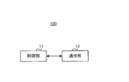
- FIG. 2 is a block diagram showing a configuration example of a part of the base station 100 according to the embodiment of the present disclosure.
- the control unit 11 determines the number of repetitions of the transmission signal (for example, the number of repetitions) and the scaling coefficient of the unit data size in the repetition.
- the data size (for example, TB size) is determined based on the information about at least one, and the communication unit 12 (for example, corresponding to the transmission circuit) transmits the transmission signal based on the data size.
- the control unit 11 is based on information regarding at least one of the number of repetitions of the received signal (for example, the number of repetitions) and the scaling coefficient of the unit data size in the repetition. ,
- the data size is determined, and the communication unit 12 (for example, corresponding to the receiving circuit) receives the received signal based on the data size.
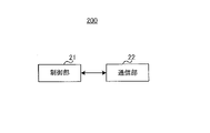
- FIG. 3 is a block diagram showing a configuration example of a part of the terminal 200 according to the embodiment of the present disclosure.
- the control unit 21 for example, corresponding to a control circuit
- the control unit 21 has at least the number of repetitions of the received signal (for example, the number of repetitions) and the scaling coefficient of the unit data size in the repetition.
- the data size (eg, TB size) is determined based on the information about one.
- the communication unit 22 (for example, corresponding to a receiving circuit) receives a received signal based on the data size. Further, in the terminal 200 shown in FIG.
- the control unit 21 is based on information regarding the number of repetitions of the transmission signal (for example, the number of repetitions) and at least one of the scaling coefficients of the unit data size in the repetition.
- the data size eg TB size.
- the communication unit 22 (for example, corresponding to a transmission circuit) transmits a transmission signal based on the data size.
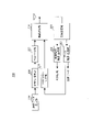
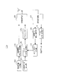
- FIG. 4 is a block diagram showing an example of the configuration of the base station 100 according to the present embodiment.
- the base station 100 includes, for example, a transmission data generation unit 101, a data coding / modulation unit 102, a repetition unit 103, a control information generation unit 104, a control information coding / modulation unit 105, and a wireless transmission unit 106.
- CH control channel
- ACK Acknowledge
- NACK Negative Acknowledge
- control unit 11 shown in FIG. 2 includes a transmission data generation unit 101, a data coding / modulation unit 102, a repetition unit 103, a control information generation unit 104, a control information coding / modulation unit 105, and data shown in FIG.
- the demodulation / decoding unit 108, the control CH demodulation / decoding unit 109, and the ACK / NACK determination unit 110 may be included.
- the communication unit 12 shown in FIG. 2 may include the radio transmission unit 106 and the radio reception unit 107 shown in FIG.
- the transmission data generation unit 101 generates, for example, transmission data (for example, downlink data), in other words, a transport block (TB).
- transmission data for example, downlink data
- TB transport block
- MIMO Multiple-Input Multiple-Output
- the transmission data generation unit 101 may generate a plurality of TBs.
- the transmission data generation unit 101 for example, when performing Repetition transmission (or repetitive transmission), is based on at least one of the number of repetitions or the scaling coefficient of the unit data size (for example, the data size for each slot).
- the TB size (or the number of information bits of transmission data) may be determined.
- the transmission data generation unit 101 outputs, for example, the generated transmission data to the data coding / modulation unit 102.
- the data coding / modulation unit 102 encodes and modulates the transmission data input from the transmission data generation unit 101, for example, and outputs the modulated signal to the repetition unit 103.
- the data coding method may be, for example, error correction coding such as a turbo code, an LDPC code, and a polar code, or may be another coding method.
- the data modulation method may be, for example, Quadrature Phase Shift Keying (QPSK) or Quadrature Amplitude Modulation (QAM), or may be another modulation method.
- QPSK Quadrature Phase Shift Keying
- QAM Quadrature Amplitude Modulation
- the data coding / modulation unit 102 divides the TB into a plurality of code blocks (CB: Code Block) and performs error correction coding in CB units. You may go. Further, the data coding / modulation unit 102 may, for example, extract a bit string corresponding to the Redundancy Version (RV) used for transmission as transmission data. Further, when performing Repetition transmission, the data coding / modulation unit 102 may use, for example, an RV having a pattern predetermined for each slot (for example, TS38.214 V16.1.0 Table 5.1.2.1-2 or Table). Specified in 5.1.2.1-3).
- RV Redundancy Version
- the data coding / modulation unit 102 holds the transmission data, for example, with respect to the data to be held (in other words, retransmission data) based on the determination result input from the ACK / NACK determination unit 110. Perform the same processing as the processing performed.
- the data coding / modulation unit 102 may refer to, for example, the TB or CB group (CBG) that retransmits, in other words, the TB or CBG for which the NACK determination result is input from the ACK / NACK determination unit 110.
- CBG CB group
- the bit string corresponding to the RV used this time may be extracted as the transmission data.
- the data coding / modulation unit 102 may discard the retained data, for example, when the determination result input from the ACK / NACK determination unit 110 indicates that there is no error in the transmission data.
- the Repetition unit 103 maps the data input from the data coding / modulation unit 102 to the resources in the time domain and the frequency domain corresponding to the specified number of slots (or time intervals), for example.
- Resources in the time domain and frequency domain may be defined, for example, by symbols and subcarriers, or resource blocks. Further, the unit of Repetition is not limited to the slot, and may be defined by other units such as a symbol and a frame.
- the Repetition unit 103 outputs the data mapped to the resource to the wireless transmission unit 106.
- the control information generation unit 104 may generate control information regarding at least one scheduling of downlink and uplink, for example.
- Information related to scheduling includes, for example, at least one resource allocation information in the time region and frequency region, Demodulation Reference Signal (DMRS) port information, coding rate and modulation method information (for example, Modulation and Coding Scheme (MCS) information).
- DMRS Demodulation Reference Signal
- MCS Modulation and Coding Scheme
- Information about HARQ eg, process ID, NDI, RV
- the control information generation unit 104 may generate, for example, information regarding the number of repetitions, or may generate information regarding a scaling coefficient (for example, Scaling factor) of the TB size.
- the control information coding / modulation unit 105 encodes and modulates the control information input from the control information generation unit 104, and outputs the modulated signal to the radio transmission unit 106, for example.
- the wireless transmission unit 106 may, for example, perform D / A conversion, up-conversion, and amplification with respect to the data signal input from the repetition unit 103 and the control information input from the control information coding / modulation unit 105.
- the transmission process is performed, and the radio signal obtained by the transmission process is transmitted from the antenna.
- the data signal corresponds to the signal transmitted by Physical Downlink Shared Channel (PDSCH), and the control information is transmitted by Downlink Control Information (DCI) or Physical Downlink Control Channel (PDCCH). Corresponds to the signal.
- DCI Downlink Control Information
- PDCCH Physical Downlink Control Channel
- the wireless reception unit 107 performs reception processing such as down-conversion and A / D conversion for signals from the terminal 200 (for example, data signals and ACK / NACK signals) received via the antenna, for example. For example, the wireless reception unit 107 outputs the data signal obtained by the reception processing to the data demodulation / decoding unit 108, and outputs the control information obtained by the reception processing to the control CH demodulation / decoding unit 109.
- reception processing such as down-conversion and A / D conversion for signals from the terminal 200 (for example, data signals and ACK / NACK signals) received via the antenna, for example.
- the wireless reception unit 107 outputs the data signal obtained by the reception processing to the data demodulation / decoding unit 108, and outputs the control information obtained by the reception processing to the control CH demodulation / decoding unit 109.
- the data signal corresponds to the signal transmitted by the Physical Uplink Shared Channel (PUSCH)
- the control information corresponds to the signal transmitted by the Physical Uplink Control Channel (PUCCH).
- PUSCH Physical Uplink Shared Channel
- PUCCH Physical Uplink Control Channel
- the data demodulation / decoding unit 108 performs channel estimation, demodulation, and decoding processing on a data reception signal such as PUSCH input from the wireless reception unit 107, for example. For example, at the time of decoding, the data demodulation / decoding unit 108 may perform the decoding process assuming the TB size based on the number of repetitions or the scaling coefficient specified at the time of data allocation of the uplink. The data demodulation / decoding unit 108 may output, for example, the decrypted data signal (in other words, received data).
- the control CH demodulation / decoding unit 109 performs channel estimation, demodulation, and decoding processing on the received signal of the control channel such as PUCCH, and outputs the ACK / NACK signal included in the received signal to the ACK / NACK determination unit 110. do.
- the ACK / NACK determination unit 110 determines ACK or NACK for the transmitted transmission data (for example, TB) based on the ACK / NACK signal input from the control CH demodulation / decoding unit 109, for example.
- the ACK / NACK determination unit 110 outputs the determination result to the data coding / modulation unit 102.
- the ACK / NACK determination unit 110 may instruct the data coding / modulation unit 102 to transmit TB or CBG.
- the ACK / NACK determination unit 110 may receive, for example, ACK / NACK information for the number of CBGs from the terminal 200.
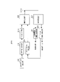
- FIG. 5 is a block diagram showing an example of the configuration of the terminal 200 according to the present embodiment.
- the terminal 200 is, for example, a wireless reception unit 201, a control information demodulation / decoding unit 202, a data demodulation / decoding unit 203, an ACK / NACK generation unit 204, a transmission data generation unit 205, and a coding / modulation unit 206. And a Repetition unit 207 and a wireless transmission unit 208.
- control unit 21 shown in FIG. 3 includes the control information demodulation / decoding unit 202, the data demodulation / decoding unit 203, the ACK / NACK generation unit 204, the transmission data generation unit 205, and the coding / modulation unit 206 shown in FIG. , And the Repetition section 207 may be included.
- the communication unit 22 shown in FIG. 3 may include the radio reception unit 201 and the radio transmission unit 208 shown in FIG.
- the wireless reception unit 201 performs reception processing such as down-conversion and A / D conversion to the signal from the base station 100 received via the antenna, and among the reception signals after the reception processing, the control channel (for example, PDCCH). ) Is output to the control information demodulation / decoding unit 202, and the data channel (for example, PDSCH) is output to the data demodulation / decoding unit 203.
- the control channel for example, PDCCH.
- the control information demodulation / decoding unit 202 demodulates and decodes a control channel (for example, PDCCH) input from the radio reception unit 201, and uses the obtained control information as another component (for example, a data demodulation / decoding unit). It may be output to 203, transmission data generation unit 205, coding / modulation unit 206 or repetition unit 207) (not shown).
- the control information may include, for example, scheduling information of at least one of a downlink and an uplink.
- the data demodulation / decoding unit 203 demodulates and error-corrects and decodes the data channel (for example, PUSCH) input from the wireless reception unit 201, for example.
- the data demodulation / decoding unit 203 specifies, for example, the modulation method and the coding rate based on the downlink scheduling information included in the control information, calculates the TB size, and calculates the TB. Processing may be performed based on the size.
- the data demodulation / decoding unit 203 may determine (for example, calculate) the TB size based on the information regarding the number of repetitions or the scaling coefficient. Further, the data demodulation / decoding unit 203 may determine whether the received data is the initial transmission data or the retransmission data based on, for example, NDI. When the received data is the first transmission data, the data demodulation / decoding unit 203 may perform error correction / decoding on the received data and make a Cyclic Redundancy Check (CRC) determination.
- CRC Cyclic Redundancy Check
- the data demodulation / decoding unit 203 performs error correction decoding after synthesizing the current received data and the past received data, and performs CRC determination, for example. good. Further, for example, when the data demodulation / decoding unit 203 is set for repetition transmission, the demodulated data may be saved, and the decoding process may be performed after receiving the data of a plurality of slots used for the repetition transmission.
- the ACK / NACK generation unit 204 generates an ACK / NACK signal based on the CRC determination result input from the data demodulation / decoding unit 203.
- the ACK / NACK generation unit 204 generates, for example, ACK in the case of CRC OK (no error) and NACK in the case of CRC NG (with error).
- the ACK / NACK generation unit 204 outputs the generated ACK / NACK signal to the wireless transmission unit 208.
- the ACK / NACK generation unit 204 When a plurality of TBs or CBs are transmitted, the ACK / NACK generation unit 204 generates an ACK / NACK signal for each of the TBs or CBs, and ACK / NACK including the plurality of ACK / NACK signals. You may generate a code block.
- the transmission data generation unit 205 generates, for example, transmission data (for example, uplink data), in other words, a transport block (TB).
- transmission data for example, uplink data
- TB transport block
- the transmission data generation unit 205 may generate a plurality of TBs.
- the transmission data generation unit 205 may determine the TB size (or the number of bits of transmission data) based on the number of repetitions or the scaling coefficient.
- the transmission data generation unit 205 outputs, for example, the generated transmission data to the coding / modulation unit 206.
- the coding / modulation unit 206 encodes and modulates the transmission data input from the transmission data generation unit 205, and outputs the modulated signal to the repetition unit 207, for example.
- the coding / modulation unit 206 may set the coding rate and the modulation method based on, for example, the received uplink scheduling information.
- the data coding method may be, for example, error correction coding such as a turbo code, an LDPC code, and a polar code, or may be another coding method.
- the data modulation method may be, for example, QPSK and QAM, or may be another modulation method.
- the coding / modulation unit 206 may divide the TB into a plurality of CBs and perform error correction coding in CB units. Further, the coding / modulation unit 206 may, for example, extract a bit string corresponding to the Redundancy Version (RV) used for transmission as transmission data. Further, when performing Repetition transmission, the coding / modulation unit 206 may use, for example, an RV having a pattern specified in advance for each slot (for example, specified in TS38.214 V16.1.0 Table 6.1.2.1-2). ..
- RV Redundancy Version
- the coding / modulation unit 206 holds, for example, transmission data, and based on the ACK / NACK signal from the base station 100, the holding data (in other words, retransmission data) is processed in the same manner as described above. Is processed.
- the coding / modulation unit 206 may extract the bit string corresponding to the RV used this time from the data encoded at the time of the previous transmission to the TB or CB group (CBG) that performs retransmission as transmission data. ..
- CBG CB group
- the coding / modulation unit 206 may discard the held data, for example.
- the Repetition unit 207 maps the data input from the coding / modulation unit 206 to the resources in the time domain and the frequency domain corresponding to the specified number of slots, for example. Resources in the time domain and frequency domain may be defined, for example, by symbols and subcarriers, or resource blocks.
- the Repetition unit 207 outputs the data mapped to the resource to the wireless transmission unit 208.
- the wireless transmission unit 208 performs D / A conversion, up-conversion, and amplification with respect to the data signal input from the Repetition unit 207 and the ACK / NACK signal input from the ACK / NACK generation unit 204.
- the transmission process is performed, and the radio signal obtained by the transmission process is transmitted from the antenna.
- FIGS. 4 and 5 mainly described the retransmission control for the downlink data
- the base station 100 and the terminal 200 may also perform the retransmission control for the uplink data in the same manner as in the case of the downlink.
- the base station 100 may generate an ACK / NACK signal based on the CRC determination result for the uplink data and transmit it to the terminal 200.
- the terminal 200 may make an ACK / NACK determination based on the ACK / NACK signal for the uplink data and control the retransmission of the uplink data (for example, TB or CBG).
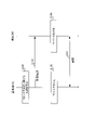
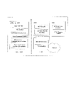
- FIG. 6 is a sequence diagram showing an operation example of the base station 100 and the terminal 200.
- the base station 100 may set, for example, information regarding determination of the TB size (S101).
- the information regarding the determination of the TB size may include, for example, the number of repetitions or the scaling factor described later.
- the base station 100 may, for example, transmit control information including information regarding the determination of the set TB size to the terminal 200 (S102).
- the base station 100 determines the TB size of at least one of the downlink data (for example, transmission data) and the uplink data (for example, reception data) based on the information regarding the determination of the set TB size (for example, the transmission data). S103).
- the terminal 200 has at least one piece of downlink data (eg, received data) and uplink data (eg, transmitted data) based on, for example, information about determining the TB size contained in the received control information.
- the TB size of is determined (S104).
- the base station 100 and the terminal 200 perform data communication on at least one of the downlink and the uplink based on the determined TB size (S105).
- the following is an example of how to set the TB size.
- the TB size may be set based on the number of repetitions.
- the TB size may be set based on the number of slots (eg, time intervals) used for Repetition, which is one of repeated transmissions.
- the TB size (for example, the number of information bits) is set based on the value (for example, also called intermediate variable) "N info " calculated according to the following equation (1) (for example). For example, TS38.214 V16.1.0 section 5.1.3 and 6.1.4).
- the TB size may be determined, for example, by further adjustment according to the value of N info . For example, the larger the value of N info , the larger the TB size may be set.
- the TB size may be set based on N info calculated according to the following equation (2).
- the larger the number of repetitions N rep the larger the TB size is set. Therefore, for example, the larger the number of repetitions N rep , the larger the number of information bits transmitted in each slot used for the repetition transmission, so that the user throughput can be improved.
- the same HARQ process is used in multiple slots used for Repetition transmission. Therefore, Repetition transmission allows more slots in the RTT to be used without increasing the number of HARQ processes. For example, in an environment where the RTT is extremely long compared to the slot length, such as the NTN environment, the user throughput can be improved by expanding the TB size based on the number of repetitions without increasing the number of HARQ processes.
- Repetition transmission increases the TB size based on an increase in the number of slots used for data transmission, so the real code rate (eg, MCS) is set when Repetition transmission is not performed. It can be set in the same way as the coding rate (for example, MCS). Therefore, even in the case of Repetition transmission, it is possible to suppress a decrease in frequency utilization efficiency (Spectral efficiency) and transmit at a necessary and sufficient error rate (for example, BLER: Block Error Rate).
- MCS real code rate
- the repetition number N rep for example, which of the equations (1) and (2) is applied
- the RRC message (or RRC signaling, It may be separately notified to the terminal 200 by MAC CE (Control Element) or DCI (also referred to as an upper layer parameter).
- MAC CE Control Element
- DCI also referred to as an upper layer parameter.
- a smaller TB size is set to improve reliability by Repetition (in other words, transmission with a low error rate). be able to.
- NTN is considering, for example, disabling retransmission by HARQ (for example, setting "HARQ-feedback disable") for traffic that requires low delay.
- HARQ for example, setting "HARQ-feedback disable”
- HARQ retransmission is invalid, HARQ retransmission is not performed, so higher reliability (for example, lower error rate) transmission is expected.
- the TB size is as shown in equation (2).
- N rep may be applied in the setting of. For example, when the retransmission control by HARQ is applied to the base station 100 and the terminal 200 (for example, when "HARQ-feedback enable" is set), or when the retransmission control by HARQ is applied (or HARQ).
- the TB size may be determined based on the Repetition number N rep according to the equation (2) for the process).
- N rep is not applied to the TB size setting as in equation (1). Therefore, reliability can be improved by Repetition (for example, transmission with a low error rate).
- the number of repetitions N rep may be notified to the terminal 200, for example, by an RRC message and at least one of DCI.
- RRC messages that set the number of repetitions, for example, "pdsch-AggregationFactor” (message for downlink), “pusch-AggregationFactor” (message for uplink), or “ConfigureGrantConfig” specified in TS38.331 V16.1.0. "RepK” (parameter for uplink Configured grant) in may be used, and other messages may be used.
- a plurality of candidates are notified (or set) to the terminal 200 by an RRC message, and one of the plurality of candidates is selected by DCI for each PDSCH or PUSCH allocation (for example, scheduling information).
- the terminal 200 may be notified.
- the RRC message for setting multiple candidates is, for example, "PDSCH-TimeDomainResourceAllocationList-r16" (message for downlink) or "repetitionNumber-" in "PUSCH-TimeDomainResourceAllocationList-r16” (message for uplink). "r16" may be used, and other messages may be used.
- the notification mechanism in the existing standard can be reused, so that the processing complexity in the terminal 200 can be reduced.
- the number of repetitions is explicitly notified to the terminal 200. Therefore, for example, the scheduling information is notified to the terminal 200 by DCI at the time of the first transmission, and the scheduling information is sent to the scheduling information in consecutive slots. Based on the same TB (eg, data of the same TB size) may be transmitted. In other words, the scheduling information does not have to be notified by DCI in each slot after the slot corresponding to the initial transmission of the Repetition transmission.
- the base station 100 may transmit the same TB in a plurality of slots (for example, repeated transmission) without notifying the terminal 200 of the number of repetitions.
- a transmission method (or retransmission method) may be referred to as, for example, "Blind retransmission" or "Open loop HARQ".
- the scheduling information may be notified to the terminal 200 by DCI in each slot.
- the base station 100 may perform retransmission without waiting for the reception of the ACK / NACK signal from the terminal 200.
- the base station 100 may transmit, for example, the same TB in continuous slots or non-continuous slots.
- the base station 100 notifies (or instructs) the terminal 200 of the retransmission of the same TB by DCI without waiting for the reception of the uplink data (for example, PUSCH) from the terminal 200, for example.
- the same TB may be transmitted to the terminal 200 using a plurality of slots.
- the base station 100 and the terminal 200 may set the TB size based on, for example, the number of repetitions N rep .
- the TB size may be set based on a scaling coefficient (or a scaling factor).
- the TB size may be set based on the scaling factor of the TB size in a plurality of slots (eg, time intervals) used for repetitive transmission.
- the TB size may be set based on N info calculated according to the following equation (3).
- the larger the scaling coefficient N scaling the larger the TB size is set. Therefore, for example, the larger the scaling coefficient N scaling , the larger the number of information bits transmitted in each slot used for repeated transmission, so that the user throughput can be improved.
- Examples of the scaling coefficient setting method include a method of setting (or notifying) semi-static to the terminal 200 by an RRC message, and a method of setting (or notifying) dynamically to the terminal 200 by DCI.
- a value of 1 or more may be set for the scaling coefficient.
- the scaling coefficient may be, for example, an integer value or a decimal value.
- a ceiling (carry-up) operation or a floor (carry-down) operation may be performed in the equation (3).
- the scaling coefficient may be notified to the terminal 200 semi-static by an RRC message.
- RRC message For example, "PDSCH-TimeDomainResourceAllocationList” or "PUSCH-TimeDomainResourceAllocationList” may be used as the RRC message for setting the scaling factor, "PDSCH-Config” or "PUSCH-Config” may be used, and other messages may be used. May be used.
- the scaling coefficient when the Repetition transmission is performed, the scaling coefficient may be applied in the TB size setting (for example, the application of the equation (3)). In other words, when the Repetition transmission is not performed, the scaling coefficient may not be applied in the TB size setting (for example, the application of the equation (1)). In other words, the base station 100 and the terminal 200 do not have to be based on the scaling coefficient when the Repetition transmission is applied and not based on the scaling coefficient when the Repetition transmission is not applied, for example, in determining the TB size.
- information indicating whether or not to apply the scaling coefficient in the TB size setting may be notified to the terminal 200. Information indicating whether or not to apply the scaling coefficient may be notified to the terminal 200 by DCI for each data scheduling, for example.
- the scaling coefficient may be set individually in the HARQ process, for example.
- the scaling coefficient may be applied to the HARQ process in which the repetition transmission is performed, and the scaling coefficient may not be applied to the HARQ process in which the repetition transmission is not performed.
- the throughput can be improved by applying the scaling factor to the HARQ process or when the retransmission by HARQ is effective. Further, for example, when retransmission by HARQ is invalid (for example, HARQ-feedback disable is set), or when the scaling coefficient is not applied to the HARQ process, transmission reliability by Repetition can be improved.
- the scaling coefficient may be notified to the terminal 200 by DCI for notifying the data scheduling information.
- a plurality of candidates for scaling coefficients may be set in the terminal 200 by an RRC message, and the scaling coefficient of any one of the plurality of candidates may be notified to the terminal 200 by DCI for each data scheduling.
- the scaling coefficient may be included in information (for example, time domain resource allocation pattern) regarding time domain resource allocation (for example, Time Domain Resource Allocation (TDRA)).
- the TDRA information may be represented, for example, in a table format (eg, a TDRA table).
- the scaling factor may be specified in the TDRA table.
- an RRC message for example, PDSCH-TimeDomainResourceAllocationList-r16 or PUSCH-TimeDomainResourceAllocationList-r16 sets a plurality of candidates for TDRA information in the terminal 200, and DCI assigns one of the plurality of candidates.
- the pattern (including the scaling coefficient) may be notified to the terminal 200.
- the scaling factor may be included in information including, for example, a scaling factor (eg, a value of 1 or less) for paging or random access processing (eg, RandomAccessChannel (RACH) response).
- Information, including scaling for paging or random access processing may be represented, for example, by a table.
- a table containing scaling factors for paging or random access processing may specify scaling factors for iterative transmission.
- a scaling factor (eg, RA-RNTI) for paging (eg, P-RNTI) or random access processing (eg, RA-RNTI) contained in the table specified in Table 5.1.3.2-2 of TS38.214 V16.1.0.
- a table may be specified that includes a scaling factor (eg, a value of 1 or more) for repeated transmissions in addition to a value of 1 or less. Further, for example, even if a plurality of candidates for scaling coefficients are set in the terminal 200 by an RRC message and a scaling coefficient of any one of the plurality of candidates is notified to the terminal 200 by DCI (for example, TB scaling field). good.
- the scaling coefficient can be notified in the notification mechanism in the existing standard, so that the processing complexity in the terminal 200 can be reduced.
- the setting method 2 for example, by expanding the TB size based on the scaling coefficient in a plurality of slots used for repetitive transmission such as Repetition transmission or Blind retransmission, the number of HARQ processes is not increased in the RTT. More slots are available. For example, in an environment where the RTT is extremely long compared to the slot length, such as the NTN environment, the user throughput can be improved by expanding the TB size based on the scaling factor without increasing the number of HARQ processes.
- the real code rate eg, MCS
- the scaling coefficient or coding rate or MCS
- transmission with a necessary and sufficient error rate for example, BLER
- the scaling coefficient can be set for the terminal 200 independently of the number of repetitions. Therefore, for example, even when Blind retransmission is applied in which the number of regressions is not explicitly notified to the terminal 200, the base station 100 and the terminal 200 are based on the number of transmissions of the same TB or the number of slots according to the scaling coefficient.
- TB size can be set.
- the larger the value set for the scaling coefficient the larger the amount of transmitted data and the lower the transmission reliability.
- the smaller the value set for the scaling coefficient the smaller the amount of transmitted data and the better the transmission reliability. In this way, by adjusting the scaling coefficient, the trade-off between the throughput and the transmission reliability can be adjusted, so that various traffics having different delay or reliability requirements can be efficiently accommodated.
- the setting method 1 and the setting method 2 may be combined.
- the setting method 1 (TB size setting based on the number of repetitions) is applied to either the downlink or the uplink
- the setting method 2 (based on the scaling coefficient) is applied to either the downlink or the uplink.
- TB size setting may be applied.
- the TB size may be set based on both the Repetition number N rep and the scaling factor N scaling .
- the equation (1) may be multiplied by the repetition number N rep and the scaling coefficient N scaling .
- the base station 100 and the terminal 200 determine the TB size based on the repetition number N rep or the scaling coefficient N scaling .
- the number of HARQ processes specified in Rel.15 / 16 (for example, up to 16). Even when using, the number of information bits that can be transmitted in the RTT can be increased by expanding the TB size in each HARQ process based on the number of slots used for repeated transmission, so that the user throughput can be improved.
- the TB size may be determined based on the number of repetitions N rep or the scaling factor N scaling after increasing the number of HARQ processes to some extent (for example, up to 32). In this case, the TB size does not become too large because the repetition number N rep or the scaling coefficient N scaling for transmitting a sufficient number of information bits in the RTT can be suppressed to some extent.
- the upper limit of the scaling coefficient for setting the TB size may be set to, for example, the number of RTT (slot) / HARQ processes, or may be set to the number of repetitions that can be set.
- the applicability of N rep or N scaling to the TB size setting may be notified to the terminal 200 by the System Information Block (SIB) for each cell.
- SIB System Information Block
- the applicability of N rep or N scaling to the TB size setting may be set and notified for each terminal 200, for example, depending on the capability of the terminal 200 (for example, UE capability).
- the terminal 200 notifies the base station 100 of the applicability of N rep or N scaling or the upper limit of the applicable N rep or N scaling
- the base station 100 notifies the base station 100 of N rep or N scaling based on the notification of the terminal 200. It may be set.
- the TB size calculated by applying N rep or N scaling may be set within a range not exceeding the upper limit of the TB size supported by the terminal 200.
- the base station 100 and the terminal 200 determine (for example, extend) the number of code block groups (CBG: Code Block Group) based on, for example, the number of repetitions or the information regarding the scaling coefficient.
- CBG Code Block Group
- multiple CBGs can be used.
- ACK / NACK is generated for each CBG, and the CBG with an error is retransmitted by HARQ, and the CBG without an error is not retransmitted by HARQ.
- Retransmission efficiency can be improved by retransmitting in CBG units.
- information regarding the number of CBGs may be notified to the terminal 200 by an RRC message.
- a plurality of code blocks may be generated for TB size data exceeding the upper limit.
- the CBG may be configured by grouping a plurality of code blocks, for example.
- the base station 100 and the terminal 200 increase the number of CBGs, for example, when the TB size is set (for example, increased) based on the number of repetitions or the scaling coefficient described in the first embodiment.
- the base station 100 when the base station 100 (for example, the transmission data generation unit 101) sets the TB size based on the number of repetitions or the scaling coefficient, the TB size setting (for example, the setting of the number of repetitions or the scaling coefficient).
- the number of CBGs may be determined based on.
- the terminal 200 for example, the data demodulation / decoding unit 203 may demodulate and decode the received data for each number of CBGs based on the TB size setting.
- the terminal 200 when the terminal 200 (for example, the transmission data generation unit 205) sets the TB size based on the number of repetitions or the scaling coefficient, the TB size setting (for example, the number of repetitions or the scaling coefficient) is set.
- the number of CBGs may be determined based on the setting).
- the base station 100 for example, the data demodulation / decoding unit 108, may demodulate and decode the received data for each number of CBGs based on the TB size setting.
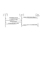
- FIG. 7 is a diagram showing a setting example of CBG.
- CBG1 and CBG2 are set.
- two ACK / NACK signals for each CBG may be transmitted to the TB transmitted in slot units.
- the TB size is 2 as compared with the case where the Repetition transmission is not applied.
- the number of CBGs may be doubled as compared to the case where the Repetition transmission is not applied because it is doubled.
- four CBGs (CBG1, CBG2, CBG3 and CBG4) including three CBs are set.
- four ACK / NACK signals for each CBG may be transmitted to the TB transmitted in the two slots.
- the number of CBGs may be set to N rep times the number of repetitions as compared to the case where the repetition transmission is not applied. Further, when the scaling factor N scaling is applied in determining the TB size, the CBG number may be set to the scaling factor N scaling times as compared with the case where the Repetition transmission is not applied, as in the case where the repetition number N rep is applied.
- An upper limit may be specified for the set value of the number of CBGs.
- the upper limit value for example, it is possible to prevent the number of CBGs from being set extremely large by the value taken by the number of repetitions N rep or the scaling factor N scaling .
- CBG transmission information (CBG TI) in the scheduling information notified to the terminal 200 by DCI.
- the CBG TI field is set, for example, to a size (eg, number of bits) that depends on the value of the CBG. Therefore, for example, the size of the CBG TI field may be set to N rep times, N scaling times, or a size based on the maximum number of CBGs according to the maximum number of CBGs.
- the size of the CBG TI field can be set to a fixed value, so that the change in DCI size depending on the suitability of N rep times or N scaling in the TB size setting is suppressed, and the number of blind decodings of the terminal 200 is increased. Can be suppressed.
- the base station 100 and the terminal 200 perform ACK / NACK based on the number of CBGs.
- the amount of PUCCH resources to send may be determined. An example of how to use the PUCCH resource that sends ACK / NACK will be described below.
- the base station 100 and the terminal 200 may use the PUCCH resource set in the terminal 200 by the RRC message or DCI over the same number of slots as the number of repetitions of data.
- the base station 100 and the terminal 200 may transmit and receive at least one of the increased ACK / NACK bits by the PUCCH resource set in the terminal 200, for example, over the same number of slots as the number of repetitions of data. ..
- the number of bits of the ACK / NACK signal transmitted over a plurality of slots may be common among the slots.
- the usage method 1 may be applied, for example, when the number of bits that can be transmitted by the PUCCH resource set in the terminal 200 is small (for example, when the number is equal to or less than the threshold value).
- the usage method 1 is effective when a PUCCH resource capable of transmitting 1 to 2 bits (for example, PUCCH format 0) is used.
- the base station 100 and the terminal 200 may increase the number of bits that can be transmitted (the number of transmission bits) in the PUCCH resource set in the terminal 200 by the RRC message or DCI.
- the base station 100 and the terminal 200 may transmit the increased ACK / NACK bits by, for example, a PUCCH resource having an increased number of bits.
- the usage method 2 may be applied, for example, when the number of bits that can be transmitted by the PUCCH resource set in the terminal 200 is large (for example, when the number is larger than the threshold value).
- the usage method 2 is effective when a PUCCH resource (for example, PUCCH format 2) capable of transmitting a number of bits larger than 2 bits is used.
- the number of CBGs increases as the TB size increases, so that the retransmission efficiency Deterioration can be suppressed. Further, for example, since the number of CBGs increases as the TB size increases, the number of ACK / NACK bits per amount of transmitted data does not increase, so that the overhead of ACK / NACK can be suppressed.
- the TB size is set based on, for example, the number of slots (eg, the number of time intervals) used to transmit downlink data (eg, PDSCH) or uplink data (eg, PUSCH) (eg, the number of time intervals). Or it may be decided).
- the number of slots eg, the number of time intervals
- PUSCH uplink data
- FIG. 8 is a block diagram showing an example of the configuration of the base station 100a according to the present embodiment.
- the same reference numerals are given to the same configurations as those of the base station 100 of the first embodiment.
- the base station 100a may include a mapping unit 103a instead of the repetition unit 103 of the first embodiment.
- the base station 100a transmits downlink data (for example, PDSCH, for example, also referred to as multi-slot PDSCH) transmitted over a plurality of slots to the terminal 200a (for example, see FIG. 9 described later). You can do it.
- the setting of the number of slots used for PDSCH transmission may be notified to the terminal 200a by, for example, at least one of DCI and RRC signaling.
- the transmission data generation unit 101 determines the TB size based on, for example, the number of slots used for PDSCH transmission. An example of a method for determining the TB size in the base station 100a will be described later.
- the mapping unit 103a maps the modulated data to resources in the time domain and frequency domain (for example, subcarriers and OFDM symbols) over the number of slots set for PDSCH transmission, for example. Further, the mapping unit 103a may perform mapping to an RS resource such as a demodulation reference signal (DMRS: Demodulation Reference Signal).
- DMRS Demodulation Reference Signal
- the base station 100a may receive, for example, uplink data (for example, PUSCH, for example, also referred to as multi-slot PUSCH) transmitted over a plurality of slots by the terminal 200.
- the data demodulation / decoding unit 108 performs channel estimation, demodulation, and decoding processing on the received PUSCH signal, for example.
- the data demodulation / decoding unit 108 may perform channel estimation using DMRS mapped to a plurality of slots.
- the data demodulation / decoding unit 108 may perform the decoding process assuming the TB size based on the number of slots used for PUSCH transmission in the decoding process, for example.
- FIG. 9 is a block diagram showing an example of the configuration of the terminal 200a according to the present embodiment.
- the same reference numerals are given to the same configurations as the terminal 200 of the first embodiment.
- the terminal 200a may include a mapping unit 207a instead of the Repetition unit 207 of the first embodiment.
- the terminal 200a may transmit uplink data (for example, PUSCH) to the base station 100a by using, for example, resources in the time domain and the frequency domain allocated from the base station 100a over a plurality of slots.
- uplink data for example, PUSCH
- the setting of the number of slots used for PUSCH transmission may be notified to the terminal 200a by, for example, at least one of DCI and RRC signaling.
- the transmission data generation unit 205 determines the TB size based on, for example, the number of slots used for PUSCH transmission. An example of a method for determining the TB size in the terminal 200a will be described later.
- the mapping unit 207a maps the modulated data to resources in the time domain and frequency domain (for example, subcarriers and OFDM symbols) over the number of slots set for PUSCH transmission, for example. Further, the mapping unit 207a may perform mapping to an RS resource such as DMRS.
- the terminal 200a may receive, for example, downlink data (for example, PDSCH) transmitted over a plurality of slots by the base station 100a.
- the data demodulation / decoding unit 203 performs channel estimation, demodulation, and decoding processing on the received PDSCH signal, for example.
- the data demodulation / decoding unit 203 may perform channel estimation using DMRS mapped to a plurality of slots.
- the data demodulation / decoding unit 203 may perform the decoding process assuming the TB size based on the number of slots used for PDSCH transmission in the decoding process, for example.
- the TB size is, for example, in "N info" represented by the formula (1) described in TS38.214 V16.1.0 section 5.1.3 (PDSCH) and 6.1.4 (PUSCH). It may be set based on.
- the base station 100a and the terminal 200a determine the value of N info based on, for example, the number of slots used for transmission of PDSCH or PUSCH.
- the base station 100a and the terminal 200a transmit PDSCH or PUSCH (in other words, transmit) with respect to N RE (the number of REs used for data transmission) included in the calculation formula of N info (for example, formula (1)).
- N RE the number of REs used for data transmission
- a value may be calculated based on the number of slots used for (signal or received signal).
- N RE may be expressed by the following equation (4).
- N'RE indicates the number of REs in one resource block (Resource Blok (RB) or Physical Resource Block (PRB)) in the slot used for data transmission
- n PRB is the data.
- the upper limit of the number of REs in the slot used for calculating the TB size is set to 156 so that the TB size does not exceed the corresponding data rate of the terminal 200a. The upper limit is not limited to 156.
- calculation method A and calculation method B two methods (for example, calculation method A and calculation method B) will be described as examples of the method for calculating the number of REs (N RE ) in the present embodiment.
- N RE may be calculated according to the following equation (5).
- N'RE indicates the number of REs allocated in the plurality of slots used for data (eg, PDSCH or PUSCH) transmission.
- N'RE may indicate the total number of REs in one resource block in each of the N slots used for data transmission.
- N slot indicates the number of slots used for data (for example, PDSCH or PUSCH) transmission.
- N'RE may be calculated according to the following equation (6).
- the Noh PRB may be notified to the terminal 200a by, for example, "PDSCH- ServingCellConfig " for PDSCH and "PUSCH-ServingCellConfig" for PUSCH.
- the overhead coefficient Noh PRB may be a coefficient for considering the overhead of a signal different from DMRS, and is specified as ⁇ 0, 6, 12, or 18 ⁇ in Rel.15 / 16 NR, for example.
- the overhead coefficient Noh PRB may be expanded by adding a value for transmission of a plurality of slots or by multiplying the coefficient.
- N slots the number of slots used for data transmission, N slots , may be applied, in which case N'RE may be calculated according to the following equation (7).
- N'RE may be calculated according to the following equation (8).
- the N DMRS PRB indicates the number of DMRS resource elements in the resource block per slot allocated for PDSCH or PUSCH transmission. According to the equation (8), for example, the N DMRS PRB and Noh PRB specified in Rel.15 / 16 NR can be applied even when transmitting in a plurality of slots, so that the processing in the terminal 200a can be simplified. ..
- N DMRS PRB indicates the number of DMRS resource elements per resource block in the slot interval (N slot interval) allocated for PDSCH or PUSCH transmission. Therefore, for example, even when the number of DMRS is set for each slot (for example, when the number is different for each slot), the accurate number of DMRS resource elements can be represented, and the base station 100a and the terminal 200a can be more accurately represented.
- the number of resource elements used for data transmission ie, N'RE ) can be calculated.
- the base station 100a and the terminal 200a are used for data transmission. You can set the TB size according to the number of slots to be played.
- the total value N'RE of the number of REs in the plurality of slots is used for calculating the TB size, so that the base station 100a and the terminal 200a have accurate N REs in the plurality of slots.
- the TB size can be set based on the value.
- the upper limit of N RE is set, so that the TB size is set extremely large by the value taken by N'RE . Can be suppressed.
- N RE may be calculated according to the following equation (9).
- N'RE indicates the number of REs in one resource block per slot of multiple slots used for data (eg, PDSCH or PUSCH) transmission.
- N slot indicates the number of slots used for data (for example, PDSCH or PUSCH) transmission.
- the calculation method B may assume, for example, that the number of REs per resource block in each of the plurality of slots used for data transmission is the same.
- N'RE may contain, for example, the number of REs in the slot with the smaller number of REs (for example, the smallest number). It may be applied and the RE number of a particular slot, such as the first slot (also referred to as the first slot) or the last slot, may be applied. Alternatively, a value based on the average value of the number of REs in each of the plurality of slots may be applied to N'RE.
- calculation method B uses the number of REs in one slot to calculate the TB size, it is possible to calculate the TB size more simply than, for example, the calculation method A.
- N RE may be calculated according to the following formula (10).
- the calculation method A and the calculation method B an example of performing a min operation in which the upper limit of the number of REs in one slot is set to 156 has been described, but the calculation method of N RE is not limited to these.
- the upper limit of the number of REs in one slot may be another value different from 156.
- the upper limit of the number of resource elements is set to 156 in a specific slot (for example, the first slot), and the upper limit of the number of resource elements is set to 168 in other slots (for example, the second and subsequent slots). May be set.
- the min operation in the formula for calculating N RE may be replaced with min (156 + 12 ⁇ 14 ⁇ (N slot -1), N ′ RE ).
- an upper limit of the number of resource elements can be appropriately set when an overhead such as DMRS is mapped to the first symbol and is not mapped to other symbols.
- N RE N'RE ⁇ n PRB
- N RE N'RE ⁇ N slot ⁇ n PRB
- the base station 100a and the terminal 200a set the TB size according to the number of slots used for data (for example, PDSCH or PUSCH) transmission, for example.
- the base station 100a and the terminal 200a determine the TB size based on the information related to the amount of resources (for example, the number of slots) used for the data (for example, the transmission signal). For example, as the number of slots used for data transmission increases, the number of information bits transmitted in each slot used for data transmission increases.
- the amount of data that can be transmitted in one HARQ process can be increased, so that the throughput can be improved even with a specified (for example, limited) number of HARQ processes.
- the TB size is set according to the number of slots used for data (for example, PDSCH or PUSCH) transmission. Therefore, for example, the number of information bits (for example, the amount of data) transmitted increases as the number of slots increases, so that the increase in the number of resource blocks is suppressed, that is, the transmission power density (PSD).
- PSD transmission power density
- the throughput can be improved while suppressing the decrease. This makes it possible to transmit data while suppressing the decrease in PSD, so that it is possible to expand the coverage area where a certain data rate can be realized, for example.
- the control overhead can be reduced.
- the consumption of HARQ processes in other words, an increase in the number of HARQ processes used
- the terminal can be simplified by reducing the number of HARQ processes.
- data transmission / reception processing such as coding or modulation is individually performed for each slot, but in the present embodiment, the base station 100a and the terminal 200a transmit data (for example, PDSCH or PUSCH) over a plurality of slots, for example. Then, by performing channel estimation collectively for a plurality of slots and performing demodulation and decoding, the channel estimation accuracy can be improved and the error rate can be reduced.
- data for example, PDSCH or PUSCH
- DMRS may be mapped to a specific slot (for example, the first slot), and DMRS may not be mapped to the remaining slots.
- the base station 100a and the terminal 200a can transmit more data. Therefore, according to the present embodiment, the TB size can be appropriately set even when the DMRS mapping is individually set for each slot (for example, when it is different for each slot).
- the number of slots used for data (for example, PDSCH or PUSCH) transmission may be paraphrased as, for example, "the number of slots that are the unit of TB processing".
- the plurality of slots used for data (for example, PDSCH or PUSCH) transmission may be temporally continuous slots or discontinuous slots.
- the frequency resources (for example, resource blocks) to which data is allocated in each of the plurality of slots may be set individually (for example, to different resources).
- the number of repetitions may be set in the number of slots N slot .
- the number of slots N slot may correspond to the number of repetitions.
- the present embodiment and the first embodiment (or the second embodiment) may be combined.
- the base station 100a and the terminal 200a are at least one of the number of repetitions of data (for example, the number of repetitions of a transmission signal), the scaling factor, and the number of slots used for transmitting data (for example, the number of time intervals).
- the TB size may be determined based on the information about the one.
- the calculated N info may be further multiplied by a scaling coefficient. For example, when N info is multiplied by a scaling factor less than 1, it is possible to transmit data with a lower MCS (or Spectral Efficiency), and the coverage area can be expanded.
- one embodiment of the present disclosure can be applied regardless of the type of satellite such as GEO, medium earth orbit satellite (MEO: Medium Earth Orbit satellite), LEO, or high orbit satellite (HEO: Highly Elliptical Orbit satellite). Further, one embodiment of the present disclosure may be applied to non-terrestrial communication such as HAPS or a drone base station.
- GEO Globalstar Satellite
- MEO Medium Earth Orbit Satellite
- LEO Long Term Evolution
- HEO Highly Elliptical Orbit satellite
- non-terrestrial communication such as HAPS or a drone base station.
- the NTN environment for example, satellite communication environment
- the present disclosure may be applied to other communication environments (eg, LTE and / or NR terrestrial cellular environments).
- it may be applied to terrestrial communication in an environment where the cell size is large and the propagation delay between the base station and the terminal is long.
- the higher the carrier frequency the wider the subcarrier spacing (SCS: subcarrier spacing), and the shorter the slot length can be.
- SCS subcarrier spacing
- the shorter the slot length the larger the number of slots in the RTT, and it is desirable to set a larger number of HARQ processes. Therefore, one embodiment of the present disclosure may be applied to, for example, a system having a higher carrier frequency for terrestrial communication (for example, a system having a carrier frequency of 52.6 GHz or higher).
- the frequency (or number of times) of decoding of control information is set once for a plurality of slots instead of the slot unit in order to reduce the processing amount or power consumption of the terminal (for example, PDCCH).
- it can be reduced to a frequency (or number of times) such as (less than the number of slots).
- by determining the TB size based on the number of slots to which the data transmitted in the plurality of slots is allocated it is possible to transmit the data amount according to the number of slots, and the throughput can be increased. Can be improved.
- data transmission using a plurality of slots not only improves the throughput but also expands the coverage area in which a certain data rate can be realized.
- One embodiment may be applied.
- the present invention is not limited to this.
- One embodiment of the present disclosure can also be applied, for example, to transmission using Semi-persistent scheduling or Configured Grant, which are scheduled periodically in advance.
- the scaling coefficient may be notified (or set) to the terminal 200 by the RRC message "SPS-Config" for Semi-persistent scheduling.
- the scaling coefficient may be notified (or set) to the terminal 200 by the RRC message "configured Grant Config" for the Configured uplink grant.
- ACK / NACK may be referred to as HARQ-ACK or HARQ-Feedback information, for example.
- Repetition may also be called, for example, slot aggregation, slot bundling, TTI aggregation, or TTI bundling.
- the number of repetitions in the first embodiment and the second embodiment may be replaced with the number of slots N slots used for data transmission (PDSCH or PUSCH).
- the number of repetitions may correspond to the number of slots N slots .
- downlink data for example, PDSCH
- uplink data for example, PUSCH
- the form of satellite communication may be configured such that the function of the base station exists on the satellite (for example, "regenerative satellite"), and the function of the base station exists on the ground and is a base.
- the communication between the station and the terminal may be relayed by a satellite (for example, “transparent satellite”).
- the downlink and uplink may be a link between a terminal and a satellite, or a link via a satellite.
- the downlink control signal (or downlink control information) related to one embodiment of the present disclosure may be, for example, a signal (or information) transmitted on the Physical Downlink Control Channel (PDCCH) of the physical layer. It may be a signal (or information) transmitted by the upper layer Medium Access Control Control Element (MAC CE) or Radio Resource Control (RRC). Further, the signal (or information) is not limited to the case of being notified by the downlink control signal, and may be predetermined in the specifications (or standards) or may be preset in the base station and the terminal.
- PDCCH Physical Downlink Control Channel
- MAC CE Medium Access Control Element
- RRC Radio Resource Control
- the signal (or information) is not limited to the case of being notified by the downlink control signal, and may be predetermined in the specifications (or standards) or may be preset in the base station and the terminal.
- the uplink control signal (or uplink control information) related to one embodiment of the present disclosure may be, for example, a signal (or information) transmitted in the PUCCH of the physical layer, and the MAC CE or the MAC CE of the upper layer or It may be a signal (or information) transmitted in RRC. Further, the signal (or information) is not limited to the case of being notified by the uplink control signal, and may be predetermined in the specifications (or standards) or may be preset in the base station and the terminal. Further, the uplink control signal may be replaced with, for example, uplink control information (UCI), 1st stage sidelink control information (SCI), or 2nd stage SCI.
- UCI uplink control information
- SCI 1st stage sidelink control information
- 2nd stage SCI 2nd stage SCI.
- the base station is a Transmission Reception Point (TRP), a cluster head, an access point, a Remote Radio Head (RRH), an eNodeB (eNB), a gNodeB (gNB), a Base Station (BS), a Base Transceiver. It may be a Station (BTS), a master unit, a gateway, or the like. Further, in side link communication, a terminal may be used instead of the base station. Further, instead of the base station, it may be a relay device that relays the communication between the upper node and the terminal. It may also be a roadside device.
- TRP Transmission Reception Point
- RRH Remote Radio Head
- eNB eNodeB
- gNB gNodeB
- BS Base Station
- BTS Base Transceiver
- a terminal may be used instead of the base station.
- the base station it may be a relay device that relays the communication between the upper node and the terminal. It may also be a roadside device.
- an embodiment of the present disclosure may be applied to any of an uplink, a downlink, and a side link, for example.
- an embodiment of the present disclosure may be an uplink Physical Uplink Shared Channel (PUSCH), a Physical Uplink Control Channel (PUCCH), a Physical Random Access Channel (PRACH), a downlink Physical Downlink Shared Channel (PDSCH), PDCCH, Physical. It may be applied to Broadcast Channel (PBCH), Physical Sidelink Shared Channel (PSSCH), Physical Sidelink Control Channel (PSCCH), or Physical Sidelink Broadcast Channel (PSBCH).
- PUSCH Physical Uplink Shared Channel
- PUCCH Physical Uplink Control Channel
- PRACH Physical Random Access Channel
- PDSCH Physical Downlink Shared Channel
- PDCCH Physical. It may be applied to Broadcast Channel (PBCH), Physical Sidelink Shared Channel (PSSCH), Physical Sidelink Control Channel (PSCCH), or Physical Sidelink Broadcast Channel (PSBCH).
- PDCCH, PDSCH, PUSCH, and PUCCH are examples of downlink control channel, downlink data channel, uplink data channel, and uplink control channel, respectively.
- PSCCH and PSSCH are examples of a side link control channel and a side link data channel.
- PBCH and PSBCH are examples of broadcast channels, and PRACH is an example of a random access channel.
- Data channel / control channel One embodiment of the present disclosure may be applied to either a data channel or a control channel, for example.
- the channel in one embodiment of the present disclosure may be replaced with any of the data channels PDSCH, PUSCH, PSSCH, or the control channels PDCCH, PUCCH, PBCH, PSCCH, PSBCH.
- the reference signal is, for example, a signal known to both base stations and mobile stations, and may also be referred to as a reference signal (RS) or pilot signal.
- the reference signal is Demodulation Reference Signal (DMRS), Channel State Information --Reference Signal (CSI-RS), Tracking Reference Signal (TRS), Phase Tracking Reference Signal (PTRS), Cell-specific Reference Signal (CRS), or Sounding. Any of the Reference Signal (SRS) may be used.
- the unit of time resource is not limited to one or a combination of slots and symbols, for example, frame, superframe, subframe, slot, timeslot subslot, minislot or symbol, Orthogonal. It may be a time resource unit such as a Frequency Division Multiplexing (OFDM) symbol or a Single Carrier --Frequency Division Multiplexing (SC-FDMA) symbol, or it may be another time resource unit. Further, the number of symbols included in one slot is not limited to the number of symbols exemplified in the above-described embodiment, and may be another number of symbols.
- OFDM Frequency Division Multiplexing
- SC-FDMA Single Carrier --Frequency Division Multiplexing
- One embodiment of the present disclosure may be applied to either a licensed band or an unlicensed band.
- One embodiment of the present disclosure is applied to any of communication between a base station and a terminal (Uu link communication), communication between a terminal and a terminal (Sidelink communication), and communication of Vehicle to Everything (V2X). May be good.
- the channel in one embodiment of the present disclosure may be replaced with any of PSCCH, PSSCH, Physical Sidelink Feedback Channel (PSFCH), PSBCH, PDCCH, PUCCH, PDSCH, PUSCH, or PBCH.
- one embodiment of the present disclosure may be applied to any of a terrestrial network, a satellite, or a non-terrestrial network (NTN: Non-Terrestrial Network) using a high altitude pseudo satellite (HAPS). .. Further, one embodiment of the present disclosure may be applied to a terrestrial network having a large transmission delay as compared with the symbol length and the slot length, such as a network having a large cell size and an ultra-wideband transmission network.
- NTN Non-Terrestrial Network
- HAPS high altitude pseudo satellite
- an antenna port refers to a logical antenna (antenna group) composed of one or more physical antennas.
- the antenna port does not necessarily refer to one physical antenna, but may refer to an array antenna or the like composed of a plurality of antennas.
- the number of physical antennas that an antenna port is composed of is not specified, but may be specified as the minimum unit that a terminal station can transmit a reference signal.
- the antenna port may also be defined as the smallest unit to multiply the weighting of the Precoding vector.
- 5G fifth-generation mobile phone technology
- NR wireless access technology
- the system architecture is assumed to be NG-RAN (Next Generation-Radio Access Network) equipped with gNB as a whole.
- the gNB provides the UE-side termination of the NG radio access user plane (SDAP / PDCP / RLC / MAC / PHY) and control plane (RRC) protocols.
- SDAP NG radio access user plane
- RRC control plane
- the gNBs are connected to each other by an Xn interface.
- gNB is converted to NGC (Next Generation Core) by the Next Generation (NG) interface, and more specifically, AMF (Access and Mobility Management Function) (for example, a specific core entity that performs AMF) by the NG-C interface.
- NGC Next Generation Core
- AMF Access and Mobility Management Function
- UPF User Plane Function
- NG-U interface For example, a specific core entity that performs UPF
- the NG-RAN architecture is shown in FIG. 10 (see, for example, 3GPP TS 38.300 v15.6.0, section 4).
- the NR user plane protocol stack (see, for example, 3GPP TS 38.300, section 4.4.1) is a PDCP (Packet Data Convergence Protocol (see Section 6.4 of TS 38.300)) sublayer, which is terminated on the network side in gNB. Includes RLC (RadioLinkControl (see Section 6.3 of TS38.300)) sublayer and MAC (Medium AccessControl (see Section 6.2 of TS38.300)) sublayer.
- RLC RadioLinkControl
- MAC Medium AccessControl
- SDAP Service Data Adaptation Protocol
- control plane protocol stack is defined for NR (see, for example, TS 38.300, section 4.4.2).
- Layer 2 functionality is given in Section 6 of TS 38.300.
- the functions of the PDCP sublayer, RLC sublayer, and MAC sublayer are listed in Sections 6.4, 6.3, and 6.2 of TS 38.300, respectively.
- the functions of the RRC layer are listed in Section 7 of TS 38.300.
- the Medium-Access-Control layer handles multiplexing of logical channels and scheduling and scheduling-related functions, including handling various numerologies.
- the physical layer is responsible for coding, PHY HARQ processing, modulation, multi-antenna processing, and mapping of signals to appropriate physical time-frequency resources.
- the physical layer also handles the mapping of transport channels to physical channels.
- the physical layer provides services to the MAC layer in the form of transport channels. Physical channels correspond to a set of time-frequency resources used to transmit a particular transport channel, and each transport channel is mapped to the corresponding physical channel.
- the physical channels include PRACH (Physical Random Access Channel), PUSCH (Physical Uplink Shared Channel), and PUCCH (Physical Uplink Control Channel) as upstream physical channels, and PDSCH (Physical Downlink Shared Channel) as downstream physical channels.
- PDCCH Physical Downlink Control Channel
- PBCH Physical Broadcast Channel
- NR use cases / deployment scenarios include enhanced mobile broadband (eMBB), ultra-reliable low-latency communications (URLLC), and massive machine type communication (mTMTC), which have diverse requirements in terms of data rate, latency, and coverage.
- eMBB is expected to support peak data rates (20 Gbps on downlink and 10 Gbps on uplink) and user-experienced data rates as high as three times the data rates provided by IMT-Advanced. ..
- URLLC more stringent requirements are imposed for ultra-low latency (0.5 ms for UL and DL respectively for user plane latency) and high reliability (1-10-5 within 1 ms).
- mMTC preferably high connection densities (1,000,000 units / km 2 equipment in urban environments), wide coverage in adverse environments, and extremely long-life batteries for low-cost equipment (15 years). Can be required.
- OFDM numerology suitable for one use case for example, subcarrier interval, OFDM symbol length, cyclic prefix (CP) length, number of symbols per scheduling interval
- CP cyclic prefix
- a low latency service preferably requires a shorter symbol length (and therefore a larger subcarrier interval) and / or a smaller number of symbols per scheduling interval (also referred to as TTI) than the mMTC service.
- TTI time-to-Time to Physical channels
- deployment scenarios with large channel delay spreads may preferably require a longer CP length than scenarios with short delay spreads.
- the subcarrier spacing may be situationally optimized to maintain similar CP overhead.
- the value of the subcarrier interval supported by NR may be one or more.
- resource element can be used to mean the smallest resource unit consisting of one subcarrier for the length of one OFDM / SC-FDMA symbol.
- resource grids of subcarriers and OFDM symbols are defined for each of the uplink and downlink for each numerology and each carrier.
- Each element of the resource grid is called a resource element and is identified based on the frequency index in the frequency domain and the symbol position in the time domain (see 3GPP TS 38.211 v15.6.0).
- FIG. 11 shows the functional separation between NG-RAN and 5GC.
- the logical node of NG-RAN is gNB or ng-eNB.
- the 5GC has logical nodes AMF, UPF, and SMF.
- gNB and ng-eNB host the following main functions: -Radio Bearer Control, Radio Admission Control, Connection Mobility Control, Dynamic allocation of resources to UEs on both uplink and downlink (scheduling), etc. Radio Resource Management function; -Data IP header compression, encryption, and integrity protection; -Selection of AMF when attaching the UE when it is not possible to determine the routing to AMF from the information provided by the UE; -Routing user plane data towards UPF; -Routing control plane information for AMF; -Set up and disconnect connections; -Scheduling and sending paging messages; -Scheduling and transmission of system notification information (sourced from AMF or Operation, Admission, Maintenance); -Measurement and measurement reporting settings for mobility and scheduling; -Transport level packet marking on the uplink; -Session management; -Network slicing support; -Management of QoS flows and mapping to data radio bearers; -Support for UEs in the RRC
- the Access and Mobility Management Function hosts the following key functions: -Ability to terminate Non-Access Stratum (NAS) signaling; -NAS signaling security; -Access Stratum (AS) security control; -Core Network (CN) node-to-node signaling for mobility between 3GPP access networks; -Reachability to UE in idle mode (including control and execution of paging retransmission); -Registration area management; -Support for in-system mobility and inter-system mobility; -Access authentication; -Access approval including roaming permission check; -Mobility management control (subscription and policy); -Network slicing support; -Select Session Management Function (SMF).
- NAS Non-Access Stratum
- AS Access Stratum
- CN Core Network
- the User Plane Function hosts the following key functions: -Anchor point for intra-RAT mobility / inter-RAT mobility (if applicable); -External PDU (Protocol Data Unit) session point for interconnection with data networks; -Packet routing and forwarding; -Packet inspection and policy rule enforcement for the user plane part; -Traffic usage report; -Uplink classifier to support the routing of traffic flows to the data network; -Branching Point to support multi-homed PDU sessions; -Quos processing for the user plane (eg packet filtering, gating, UL / DL rate enforcement); -Verification of uplink traffic (mapping of SDF to QoS flow); -Downlink packet buffering and downlink data notification trigger function.
- -Anchor point for intra-RAT mobility / inter-RAT mobility if applicable
- -External PDU Protocol Data Unit
- -Packet routing and forwarding -Packet inspection and policy rule enforcement for the user plane part
- Session Management Function hosts the following key functions: -Session management; -IP address assignment and management for UEs; -UPF selection and control; -Traffic steering setting function in User Plane Function (UPF) for routing traffic to appropriate destinations; -Control policy enforcement and QoS; -Notification of downlink data.
- FIG. 12 shows some of the NAS part's interactions between the UE, gNB, and AMF (5GC entity) as the UE transitions from RRC_IDLE to RRC_CONNECTED (see TS 38.300 v15.6.0).
- RRC is an upper layer signaling (protocol) used to set UE and gNB.
- AMF will prepare UE context data (which includes, for example, PDU session context, security key, UE RadioCapability, UESecurityCapabilities, etc.) and the initial context.
- UE context data which includes, for example, PDU session context, security key, UE RadioCapability, UESecurityCapabilities, etc.
- gNB activates AS security together with UE. This is done by the gNB sending a SecurityModeCommand message to the UE and the UE responding to the gNB with a SecurityModeComplete message.
- the gNB sends an RRC Reconfiguration message to the UE, and the gNB receives the RRC Reconfiguration Complete from the UE for this, so that the signaling Radio Bearer 2 (SRB 2) and the Data Radio Bearer (DRB) are reconfigured to be set up. ..
- SRB 2 Signaling Radio Bearer 2
- DRB Data Radio Bearer
- the steps for RRC Reconfiguration are omitted because SRB2 and DRB are not set up.
- gNB notifies AMF that the setup procedure is completed by the initial context setup response (INITIALCONTEXTSETUPRESPONSE).
- the control circuit that establishes the Next Generation (NG) connection with gNodeB during operation and the signaling radio bearer between gNodeB and the user equipment (UE: User Equipment) are set up so as to be NG during operation.
- a 5th Generation Core (5GC) entity eg, AMF, SMF, etc.
- gNodeB transmits RadioResourceControl (RRC) signaling including a resource allocation setting information element (IE: Information Element) to the UE via a signaling radio bearer. Then, the UE performs transmission on the uplink or reception on the downlink based on the resource allocation setting.
- RRC RadioResourceControl
- FIG. 13 shows some of the use cases for 5G NR.
- the 3rd generation partnership project new radio (3GPP NR) considers three use cases envisioned by IMT-2020 to support a wide variety of services and applications.
- the formulation of the first stage specifications for high-capacity and high-speed communication (eMBB: enhanced mobile-broadband) has been completed.
- eMBB enhanced mobile-broadband
- URLLC ultra-reliable and low-latency communications
- mTC multi-concurrent machine type communications
- Standardization for massive machine-type communications is included.
- FIG. 13 shows some examples of conceptual use scenarios for IMT since 2020 (see, eg, ITU-R M. 2083 FIG. 2).
- URLLC use cases have strict performance requirements such as throughput, latency, and availability.
- the URLLC use case is envisioned as one of the elemental technologies for realizing these future applications such as wireless control of industrial production process or manufacturing process, telemedicine surgery, automation of power transmission and distribution in smart grid, traffic safety, etc. ing.
- the ultra-high reliability of URLLC is supported by identifying techniques that meet the requirements set by TR 38.913.
- the important requirement is that the latency of the target user plane is 0.5 ms for UL (uplink) and 0.5 ms for DL (downlink).
- the general requirement of URLLC for one packet transmission is that when the latency of the user plane is 1 ms, the block error rate (BLER: block error rate) is 1E-5 for the packet size of 32 bytes.
- BLER block error rate
- the technological enhancement aimed at by NR URLLC aims to improve latency and reliability.
- Technology enhancements to improve latency include configurable numerology, non-slot-based scheduling with flexible mapping, grant-free (configured grant) uplinks, slot-level iterations in data channels, and And includes pre-emption on the downlink. Preemption means that a transmission that has already been allocated a resource is stopped and that already allocated resource is used for other transmissions with later requested lower latency / higher priority requirements. Therefore, a transmission that has already been permitted will be replaced by a later transmission. Preemption is applicable regardless of the specific service type. For example, the transmission of service type A (URLLC) may be replaced by the transmission of service type B (eMBB, etc.).
- Technical enhancements for reliability improvement include a dedicated CQI / MCS table for the 1E-5 goal BLER.
- a feature of the mMTC (massive machine type communication) use case is that the number of connected devices that transmit a relatively small amount of data, which is typically less susceptible to delays, is extremely large.
- the device is required to be inexpensive and have a very long battery life. From an NR perspective, utilizing a very narrow bandwidth portion is one solution that saves power and allows for longer battery life from the perspective of the UE.
- Strict requirements are high reliability (reliability up to 10-6 levels), high availability, packet size up to 256 bytes, time synchronization up to a few microseconds (values depending on the use case). It can be 1 ⁇ s or several ⁇ s depending on the frequency range and short latencies of about 0.5 ms to 1 ms (eg, 0.5 ms latency in the target user plane).
- NR URLLC there may be some technical enhancements from the viewpoint of the physical layer. These technical enhancements include the enhancement of PDCCH (Physical Downlink Control Channel) for compact DCI, the repetition of PDCCH, and the increase of PDCCH monitoring.
- the enhancement of UCI Uplink Control Information
- HARQ Hybrid Automatic Repeat Request
- CSI feedback There may also be enhancements to the PUSCH associated with minislot level hopping and enhancements to retransmission / repetition.
- mini slot refers to a Transmission Time Interval (TTI) that contains fewer symbols than a slot (a slot comprises 14 symbols).
- the 5G QoS (Quality of Service) model is based on a QoS flow, and a QoS flow (GBR: Guaranteed Bit Rate QoS flow) that requires a guaranteed flow bit rate and a guaranteed flow bit rate are required. Supports any non-GBR QoS flow (non-GBR QoS flow). Therefore, at the NAS level, QoS flow is the finest grain size QoS segment in a PDU session.
- the QoS flow is specified in the PDU session by the QoS flow ID (QFI: QoS Flow ID) carried in the encapsulation header via the NG-U interface.
- QFI QoS Flow ID
- 5GC For each UE, 5GC establishes one or more PDU sessions. For each UE, for a PDU session, the NG-RAN establishes at least one Data Radio Bearers (DRB), eg, as shown above with reference to FIG. Also, an additional DRB for the QoS flow of the PDU session can be set later (when to set it depends on NG-RAN).
- DRB Data Radio Bearers
- NG-RAN maps packets belonging to different PDU sessions to different DRBs.
- NAS level packet filters in UEs and 5GCs associate UL packets and DL packets with QoS flows, whereas AS level mapping rules in UEs and NG-RANs associate UL QoS flows and DL QoS flows with DRBs.
- FIG. 14 shows a non-roaming reference architecture of 5G NR (see TS 23.501 v16.1.0, section 4.23).
- the Application Function (AF) (for example, the external application server that hosts the 5G service illustrated in FIG. 13) interacts with the 3GPP core network to provide the service. For example, accessing a Network Exposure Function (NEF) to support an application that affects traffic routing, or interacting with a policy framework for policy control (eg, QoS control) (Policy Control Function). (PCF)).
- NEF Network Exposure Function
- PCF Policy Control Function
- the Application Function that is considered trusted by the operator can interact directly with the associated Network Function.
- An Application Function that is not allowed direct access to the Network Function by the operator interacts with the relevant Network Function using the release framework to the outside via the NEF.
- FIG. 14 shows a further functional unit of the 5G architecture, that is, Network Slice Selection Function (NSSF), Network Repository Function (NRF), Unified Data Management (UDM), Authentication Server Function (AUSF), Access and Mobility Management Function (AMF). , Session Management Function (SMF), and Data Network (DN, eg, service by operator, Internet access, or service by a third party). All or part of the core network functions and application services may be deployed and operate in a cloud computing environment.
- NSSF Network Slice Selection Function
- NRF Network Repository Function
- UDM Unified Data Management
- AUSF Authentication Server Function
- AMF Access and Mobility Management Function
- SMF Session Management Function
- DN Data Network
- the QoS requirement for at least one of the URLLC service, the eMMB service, and the mMTC service at the time of operation is set.
- An application server eg, AF with 5G architecture
- Each functional block used in the description of the above embodiment is partially or wholly realized as an LSI which is an integrated circuit, and each process described in the above embodiment is partially or wholly. It may be controlled by one LSI or a combination of LSIs.
- the LSI may be composed of individual chips, or may be composed of one chip so as to include a part or all of functional blocks.
- the LSI may include data input and output.
- LSIs may be referred to as ICs, system LSIs, super LSIs, and ultra LSIs depending on the degree of integration.
- the method of making an integrated circuit is not limited to LSI, and may be realized by a dedicated circuit, a general-purpose processor, or a dedicated processor. Further, an FPGA (Field Programmable Gate Array) that can be programmed after the LSI is manufactured, or a reconfigurable processor that can reconfigure the connection and settings of the circuit cells inside the LSI may be used.
- FPGA Field Programmable Gate Array
- the present disclosure may be realized as digital processing or analog processing.
- the communication device may include a wireless transceiver and a processing / control circuit.
- the wireless transceiver may include a receiver and a transmitter, or them as a function.
- the radio transceiver (transmitter, receiver) may include an RF (Radio Frequency) module and one or more antennas.
- the RF module may include an amplifier, an RF modulator / demodulator, or the like.
- Non-limiting examples of communication devices include telephones (mobile phones, smartphones, etc.), tablets, personal computers (PCs) (laptops, desktops, notebooks, etc.), cameras (digital stills / video cameras, etc.).
- Digital players digital audio / video players, etc.
- wearable devices wearable cameras, smart watches, tracking devices, etc.
- game consoles digital book readers
- telehealth telemedicines remote health Care / medicine prescription
- vehicles with communication functions or mobile transportation automobiles, planes, ships, etc.
- combinations of the above-mentioned various devices can be mentioned.
- Communication devices are not limited to those that are portable or mobile, but are all types of devices, devices, systems that are non-portable or fixed, such as smart home devices (home appliances, lighting equipment, smart meters or Includes measuring instruments, control panels, etc.), vending machines, and any other "Things” that can exist on the IoT (Internet of Things) network.
- smart home devices home appliances, lighting equipment, smart meters or Includes measuring instruments, control panels, etc.
- vending machines and any other “Things” that can exist on the IoT (Internet of Things) network.
- Communication includes data communication by a combination of these, in addition to data communication by a cellular system, a wireless LAN system, a communication satellite system, etc.
- the communication device also includes devices such as controllers and sensors that are connected or connected to communication devices that perform the communication functions described in the present disclosure.
- devices such as controllers and sensors that are connected or connected to communication devices that perform the communication functions described in the present disclosure.
- controllers and sensors that generate control and data signals used by communication devices that perform the communication functions of the communication device.
- Communication devices also include infrastructure equipment that communicates with or controls these non-limiting devices, such as base stations, access points, and any other device, device, or system. ..
- the communication device includes a control circuit for determining a data size based on information regarding the number of repetitions of a transmission signal and at least one scaling coefficient of a unit data size in the repetition, and the above-mentioned communication device.
- a transmission circuit for transmitting the transmission signal based on the data size is provided.
- the information indicates the number of time intervals for the iteration.
- control circuit is based on the number of iterations when the retransmission control is applied and not on the number of iterations when the retransmission control is not applied in determining the data size.
- control circuit is based on the scaling factor when the iteration is applied and not based on the scaling factor when the iteration is not applied in determining the data size.
- control circuit determines the data size based on the scaling factor in the retransmission process to which the iteration is applied among a plurality of retransmission processes.
- the terminal when the communication device is a terminal, the terminal receives the information from a base station, and when the communication device is a base station, the base station sends the information to the terminal. Send.
- the scaling factor is defined in the information regarding time domain resource allocation.
- the scaling factor is defined in the information including the scaling factor for paging and random access.
- the scaling factor is an integer value or a decimal value of 1 or more.
- control circuit determines the number of groups of code blocks obtained by dividing the data included in the transmission signal based on the information.
- control circuit determines the resource amount of the response signal to the data based on the number of groups.
- the communication device includes a control circuit for determining a data size based on information regarding the number of repetitions of a received signal and at least one scaling coefficient of a unit data size in the repetition, and the above-mentioned communication device.
- a receiving circuit for receiving the received signal based on the data size is provided.
- the communication device determines the data size based on the number of repetitions of the transmission signal and information on at least one of the scaling coefficients of the unit data size in the repetition.
- the transmission signal is transmitted based on the data size.
- the communication device determines the data size based on the number of repetitions of the received signal and at least one of the scaling coefficients of the unit data size in the repetition.
- the received signal is received based on the data size.
- the communication device has a control circuit that determines a data size based on information about the number of time intervals used for a transmission signal, and transmission of the transmission signal based on the data size. It is provided with a transmission circuit to perform.
- control circuit determines the data size based on the number of resource elements allocated to the transmit signal in the time interval used for the transmit signal.
- the number of time intervals corresponds to the number of repetitions of the transmitted signal.
- One aspect of the present disclosure is useful for wireless communication systems.
- Base station 101,205 Transmission data generation unit 102 Data coding / modulation unit 103, 207 Repetition unit 103a, 207a Mapping unit 104 Control information generation unit 105 Control information coding / modulation unit 106, 208 Wireless transmission unit 107, 201 Wireless receiver 108, 203 Data demodulation / decoding unit 109 Control CH demodulation / decoding unit 110 ACK / NACK judgment unit 200, 200a Terminal 202 Control information demodulation / decoding unit 204 ACK / NACK generation unit 206 Coding / modulation unit
Abstract
Description
Rel. 15は、例えば、地上ネットワーク向けの無線アクセス技術に関する仕様である。一方、NRは、衛星又は高高度疑似衛星(HAPS:High-altitude platform station)を用いた通信といった非地上系のネットワーク(NTN)への拡張が検討されている(例えば、非特許文献1)。
Long Term Evolution(LTE)又は5G NRでは、例えば、データ送信の際の再送制御にHARQが適用される。
[無線通信システムの概要]
本開示の一実施の形態に係る無線通信システムは、例えば、少なくとも、基地局100及び端末200を備える。無線通信システムは、例えば、NTN環境の衛星通信システムでもよく、他の無線通信システムでもよい。
図4は、本実施の形態に係る基地局100の構成の一例を示すブロック図である。基地局100は、例えば、送信データ生成部101と、データ符号化・変調部102と、Repetition部103と、制御情報生成部104と、制御情報符号化・変調部105と、無線送信部106と、無線受信部107と、データ復調・復号部108と、制御チャネル(CH)復調・復号部109と、ACK(Acknowledge)/NACK(Negative Acknowledge)判定部110と、を含む。
図5は、本実施の形態に係る端末200の構成の一例を示すブロック図である。端末200は、例えば、無線受信部201と、制御情報復調・復号部202と、データ復調・復号部203と、ACK/NACK生成部204と、送信データ生成部205と、符号化・変調部206と、Repetition部207と、無線送信部208と、を含む。
次に、上述した基地局100及び端末200の動作例について説明する。
設定方法1では、例えば、TBサイズは、Repetition数に基づいて設定されてよい。換言すると、TBサイズは、繰り返し送信の一つであるRepetitionに使用されるスロット(例えば、時間区間)の数に基づいて設定されてよい。


設定方法2では、例えば、TBサイズは、スケーリング係数(又は、scaling factorと呼ぶ)に基づいて設定されてよい。換言すると、TBサイズは、繰り返し送信に使用される複数のスロット(例えば、時間区間)におけるTBサイズのスケーリング係数に基づいて設定されてよい。

本開示の一実施の形態に係る基地局及び端末の構成は、実施の形態1と同様でよい。
使用方法1では、例えば、基地局100及び端末200は、RRCメッセージ又はDCIによって端末200に設定されるPUCCHリソースを、データのRepetition数と同じ数のスロットに亘って使用してよい。
使用方法2では、例えば、基地局100及び端末200は、RRCメッセージ又はDCIによって端末200に設定されるPUCCHリソースにおいて送信可能なビット数(送信ビット数)を増加させてよい。
本実施の形態では、TBサイズは、例えば、下りリンクデータ(例えば、PDSCH)又は上りリンクデータ(例えば、PUSCH)の送信に使用されるスロット数(例えば、時間区間の数)に基づいて設定(或いは決定)されてよい。
図8は、本実施の形態に係る基地局100aの構成の一例を示すブロック図である。図8において、実施の形態1の基地局100と同様の構成には同一の符号を付す。例えば、基地局100aは、実施の形態1のRepetition部103の代わりに、マッピング部103aを備えてよい。
図9は、本実施の形態に係る端末200aの構成の一例を示すブロック図である。図9において、実施の形態1の端末200と同様の構成には同一の符号を付す。例えば、端末200aは、実施の形態1のRepetition部207の代わりに、マッピング部207aを備えてよい。
本実施の形態におけるTBサイズの決定方法の例について説明する。

算出方法Aでは、NREは、次式(5)に従って算出されてよい。

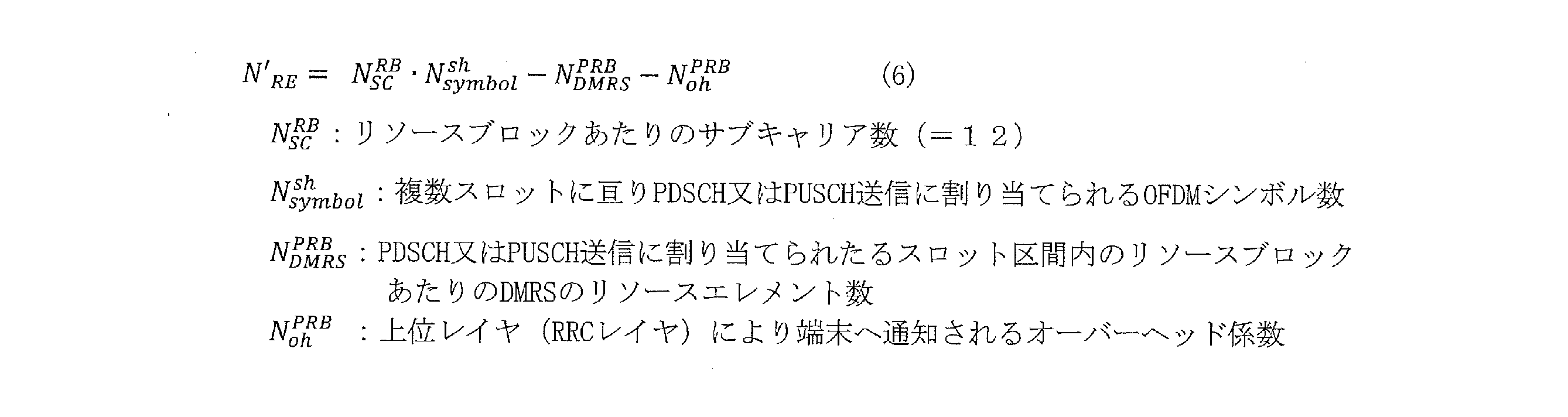


算出方法Bでは、NREは、次式(9)に従って算出されてよい。


本開示において、本開示の一実施例に関連する下り制御信号(又は、下り制御情報)は、例えば、物理層のPhysical Downlink Control Channel(PDCCH)において送信される信号(又は、情報)でもよく、上位レイヤのMedium Access Control Control Element(MAC CE)又はRadio Resource Control(RRC)において送信される信号(又は、情報)でもよい。また、信号(又は、情報)は、下り制御信号によって通知される場合に限定されず、仕様(又は、規格)において予め規定されてもよく、基地局及び端末に予め設定されてもよい。
本開示の一実施例において、基地局は、Transmission Reception Point(TRP)、クラスタヘッド、アクセスポイント、Remote Radio Head(RRH)、eNodeB (eNB)、gNodeB(gNB)、Base Station(BS)、Base Transceiver Station(BTS)、親機、ゲートウェイなどでもよい。また、サイドリンク通信では、基地局の代わりに端末としてもよい。また、基地局の代わりに、上位ノードと端末の通信を中継する中継装置であってもよい。また、路側器であってもよい。
本開示の一実施例は、例えば、上りリンク、下りリンク、及び、サイドリンクの何れに適用してもよい。例えば、本開示の一実施例を上りリンクのPhysical Uplink Shared Channel(PUSCH)、Physical Uplink Control Channel(PUCCH)、Physical Random Access Channel(PRACH)、下りリンクのPhysical Downlink Shared Channel(PDSCH)、PDCCH、Physical Broadcast Channel(PBCH)、又は、サイドリンクのPhysical Sidelink Shared Channel(PSSCH)、Physical Sidelink Control Channel(PSCCH)、Physical Sidelink Broadcast Channel(PSBCH)に適用してもよい。
本開示の一実施例は、例えば、データチャネル及び制御チャネルの何れに適用してもよい。例えば、本開示の一実施例におけるチャネルをデータチャネルのPDSCH、PUSCH、PSSCH、又は、制御チャネルのPDCCH、PUCCH、PBCH、PSCCH、PSBCHの何れかに置き換えてもよい。
本開示の一実施例において、参照信号は、例えば、基地局及び移動局の双方で既知の信号であり、Reference Signal(RS)又はパイロット信号と呼ばれることもある。参照信号は、Demodulation Reference Signal(DMRS)、Channel State Information - Reference Signal(CSI-RS)、Tracking Reference Signal(TRS)、Phase Tracking Reference Signal(PTRS)、Cell-specific Reference Signal(CRS)、又は、Sounding Reference Signal(SRS)の何れでもよい。
本開示の一実施例において、時間リソースの単位は、スロット及びシンボルの1つ又は組み合わせに限らず、例えば、フレーム、スーパーフレーム、サブフレーム、スロット、タイムスロットサブスロット、ミニスロット又は、シンボル、Orthogonal Frequency Division Multiplexing(OFDM)シンボル、Single Carrier - Frequency Division Multiplexing(SC-FDMA)シンボルといった時間リソース単位でもよく、他の時間リソース単位でもよい。また、1スロットに含まれるシンボル数は、上述した実施の形態において例示したシンボル数に限定されず、他のシンボル数でもよい。
本開示の一実施例は、ライセンスバンド、アンライセンスバンドのいずれに適用してもよい。
本開示の一実施例は、基地局と端末との間の通信(Uuリンク通信)、端末と端末との間の通信(Sidelink通信)、Vehicle to Everything(V2X)の通信のいずれに適用してもよい。例えば、本開示の一実施例におけるチャネルをPSCCH、PSSCH、Physical Sidelink Feedback Channel(PSFCH)、PSBCH、PDCCH、PUCCH、PDSCH、PUSCH、又は、PBCHの何れかに置き換えてもよい。
本開示の一実施例において、アンテナポートは、1本又は複数の物理アンテナから構成される論理的なアンテナ(アンテナグループ)を指す。例えば、アンテナポートは必ずしも1本の物理アンテナを指すとは限らず、複数のアンテナから構成されるアレイアンテナ等を指すことがある。例えば、アンテナポートが何本の物理アンテナから構成されるかは規定されず、端末局が基準信号(Reference signal)を送信できる最小単位として規定されてよい。また、アンテナポートはプリコーディングベクトル(Precoding vector)の重み付けを乗算する最小単位として規定されることもある。
3GPPは、100GHzまでの周波数範囲で動作する新無線アクセス技術(NR)の開発を含む第5世代携帯電話技術(単に「5G」ともいう)の次のリリースに向けて作業を続けている。5G規格の初版は2017年の終わりに完成しており、これにより、5G NRの規格に準拠した端末(例えば、スマートフォン)の試作および商用展開に移ることが可能である。
図11は、NG-RANと5GCとの間の機能分離を示す。NG-RANの論理ノードは、gNBまたはng-eNBである。5GCは、論理ノードAMF、UPF、およびSMFを有する。
- 無線ベアラ制御(Radio Bearer Control)、無線アドミッション制御(Radio Admission Control)、接続モビリティ制御(Connection Mobility Control)、上りリンクおよび下りリンクの両方におけるリソースのUEへの動的割当(スケジューリング)等の無線リソース管理(Radio Resource Management)の機能;
- データのIPヘッダ圧縮、暗号化、および完全性保護;
- UEが提供する情報からAMFへのルーティングを決定することができない場合のUEのアタッチ時のAMFの選択;
- UPFに向けたユーザプレーンデータのルーティング;
- AMFに向けた制御プレーン情報のルーティング;
- 接続のセットアップおよび解除;
- ページングメッセージのスケジューリングおよび送信;
- システム報知情報(AMFまたは運用管理保守機能(OAM:Operation, Admission, Maintenance)が発信源)のスケジューリングおよび送信;
- モビリティおよびスケジューリングのための測定および測定報告の設定;
- 上りリンクにおけるトランスポートレベルのパケットマーキング;
- セッション管理;
- ネットワークスライシングのサポート;
- QoSフローの管理およびデータ無線ベアラに対するマッピング;
- RRC_INACTIVE状態のUEのサポート;
- NASメッセージの配信機能;
- 無線アクセスネットワークの共有;
- デュアルコネクティビティ;
- NRとE-UTRAとの緊密な連携。
- Non-Access Stratum(NAS)シグナリングを終端させる機能;
- NASシグナリングのセキュリティ;
- Access Stratum(AS)のセキュリティ制御;
- 3GPPのアクセスネットワーク間でのモビリティのためのコアネットワーク(CN:Core Network)ノード間シグナリング;
- アイドルモードのUEへの到達可能性(ページングの再送信の制御および実行を含む);
- 登録エリアの管理;
- システム内モビリティおよびシステム間モビリティのサポート;
- アクセス認証;
- ローミング権限のチェックを含むアクセス承認;
- モビリティ管理制御(加入およびポリシー);
- ネットワークスライシングのサポート;
- Session Management Function(SMF)の選択。
- intra-RATモビリティ/inter-RATモビリティ(適用可能な場合)のためのアンカーポイント;
- データネットワークとの相互接続のための外部PDU(Protocol Data Unit)セッションポイント;
- パケットのルーティングおよび転送;
- パケット検査およびユーザプレーン部分のポリシールールの強制(Policy rule enforcement);
- トラフィック使用量の報告;
- データネットワークへのトラフィックフローのルーティングをサポートするための上りリンククラス分類(uplink classifier);
- マルチホームPDUセッション(multi-homed PDU session)をサポートするための分岐点(Branching Point);
- ユーザプレーンに対するQoS処理(例えば、パケットフィルタリング、ゲーティング(gating)、UL/DLレート制御(UL/DL rate enforcement);
- 上りリンクトラフィックの検証(SDFのQoSフローに対するマッピング);
- 下りリンクパケットのバッファリングおよび下りリンクデータ通知のトリガ機能。
- セッション管理;
- UEに対するIPアドレスの割当および管理;
- UPFの選択および制御;
- 適切な宛先にトラフィックをルーティングするためのUser Plane Function(UPF)におけるトラフィックステアリング(traffic steering)の設定機能;
- 制御部分のポリシーの強制およびQoS;
- 下りリンクデータの通知。
図12は、NAS部分の、UEがRRC_IDLEからRRC_CONNECTEDに移行する際のUE、gNB、およびAMF(5GCエンティティ)の間のやり取りのいくつかを示す(TS 38.300 v15.6.0参照)。
図13は、5G NRのためのユースケースのいくつかを示す。3rd generation partnership project new radio(3GPP NR)では、多種多様なサービスおよびアプリケーションをサポートすることがIMT-2020によって構想されていた3つのユースケースが検討されている。大容量・高速通信(eMBB:enhanced mobile-broadband)のための第一段階の仕様の策定が終了している。現在および将来の作業には、eMBBのサポートを拡充していくことに加えて、高信頼・超低遅延通信(URLLC:ultra-reliable and low-latency communications)および多数同時接続マシンタイプ通信(mMTC:massive machine-type communicationsのための標準化が含まれる。図13は、2020年以降のIMTの構想上の利用シナリオのいくつかの例を示す(例えばITU-R M.2083 図2参照)。
5GのQoS(Quality of Service)モデルは、QoSフローに基づいており、保証されたフロービットレートが求められるQoSフロー(GBR:Guaranteed Bit Rate QoSフロー)、および、保証されたフロービットレートが求められないQoSフロー(非GBR QoSフロー)をいずれもサポートする。したがって、NASレベルでは、QoSフローは、PDUセッションにおける最も微細な粒度のQoSの区分である。QoSフローは、NG-Uインタフェースを介してカプセル化ヘッダ(encapsulation header)において搬送されるQoSフローID(QFI:QoS Flow ID)によってPDUセッション内で特定される。
101,205 送信データ生成部
102 データ符号化・変調部
103,207 Repetition部
103a,207a マッピング部
104 制御情報生成部
105 制御情報符号化・変調部
106,208 無線送信部
107,201 無線受信部
108,203 データ復調・復号部
109 制御CH復調・復号部
110 ACK/NACK判定部
200,200a 端末
202 制御情報復調・復号部
204 ACK/NACK生成部
206 符号化・変調部
Claims (17)
- 送信信号の繰り返しの回数、及び、前記繰り返しにおける単位データサイズのスケーリング係数の少なくとも一つに関する情報に基づいて、データサイズを決定する制御回路と、
前記データサイズに基づいて、前記送信信号の送信を行う送信回路と、
を具備する通信装置。 - 前記情報は、前記繰り返しのための時間区間の数を示す、
請求項1に記載の通信装置。 - 前記制御回路は、前記データサイズの決定において、再送制御を適用する場合に前記繰り返しの回数に基づき、前記再送制御を適用しない場合に前記繰り返しの回数に基づかない、
請求項1に記載の通信装置。 - 前記制御回路は、前記データサイズの決定において、前記繰り返しを適用する場合に前記スケーリング係数に基づき、前記繰り返しを適用しない場合に前記スケーリング係数に基づかない、
請求項1に記載の通信装置。 - 前記制御回路は、複数の再送プロセスのうち、前記繰り返しが適用される再送プロセスにおいて、前記スケーリング係数に基づいて前記データサイズを決定する、
請求項1に記載の通信装置。 - 前記通信装置が端末である場合、前記端末は、前記情報を、基地局から受信し、前記通信装置が基地局である場合、前記基地局は端末へ前記情報を送信する、
請求項1に記載の通信装置。 - 前記スケーリング係数は、時間領域リソース割当に関する情報において規定される、
請求項1に記載の通信装置。 - 前記スケーリング係数は、ページング及びランダムアクセスに対するスケーリング係数を含む情報において規定される、
請求項1に記載の通信装置。 - 前記スケーリング係数は、1以上の整数値又は小数値である、
請求項1に記載の通信装置。 - 前記制御回路は、前記送信信号に含まれるデータを分割したコードブロックのグループ数を、前記情報に基づいて決定する、
請求項1に記載の通信装置。 - 前記制御回路は、前記グループ数に基づいて、前記データに対する応答信号のリソース量を決定する、
請求項10に記載の通信装置。 - 受信信号の繰り返しの回数、及び、前記繰り返しにおける単位データサイズのスケーリング係数の少なくとも一つに関する情報に基づいて、データサイズを決定する制御回路と、
前記データサイズに基づいて、前記受信信号の受信を行う受信回路と、
を具備する通信装置。 - 通信装置は、
送信信号の繰り返しの回数、及び、前記繰り返しにおける単位データサイズのスケーリング係数の少なくとも一つに関する情報に基づいて、データサイズを決定し、
前記データサイズに基づいて、前記送信信号の送信を行う、
通信方法。 - 通信装置は、
受信信号の繰り返しの回数、及び、前記繰り返しにおける単位データサイズのスケーリング係数の少なくとも一つに関する情報に基づいて、データサイズを決定し、
前記データサイズに基づいて、前記受信信号の受信を行う、
通信方法。 - 送信信号に使用される時間区間の数に関する情報に基づいて、データサイズを決定する制御回路と、
前記データサイズに基づいて、前記送信信号の送信を行う送信回路と、
を具備する通信装置。 - 前記制御回路は、前記送信信号に使用される前記時間区間において前記送信信号に割り当てられるリソースエレメント数に基づいて、前記データサイズを決定する、
請求項15に記載の通信装置。 - 前記時間区間の数は、前記送信信号の繰り返しの回数に対応する、
請求項16に記載の通信装置。
Priority Applications (4)
| Application Number | Priority Date | Filing Date | Title |
|---|---|---|---|
| CN202180071636.3A CN116438757A (zh) | 2020-10-21 | 2021-07-13 | 通信装置及通信方法 |
| US18/249,518 US20230388982A1 (en) | 2020-10-21 | 2021-07-13 | Communication device and communication method |
| JP2022556409A JPWO2022085254A5 (ja) | 2021-07-13 | 通信装置、通信方法及び集積回路 | |
| EP21882395.3A EP4236135A4 (en) | 2020-10-21 | 2021-07-13 | COMMUNICATION DEVICE AND COMMUNICATION METHOD |
Applications Claiming Priority (4)
| Application Number | Priority Date | Filing Date | Title |
|---|---|---|---|
| JP2020-176833 | 2020-10-21 | ||
| JP2020176833 | 2020-10-21 | ||
| JP2021005151 | 2021-01-15 | ||
| JP2021-005151 | 2021-01-15 |
Publications (1)
| Publication Number | Publication Date |
|---|---|
| WO2022085254A1 true WO2022085254A1 (ja) | 2022-04-28 |
Family
ID=81291206
Family Applications (1)
| Application Number | Title | Priority Date | Filing Date |
|---|---|---|---|
| PCT/JP2021/026327 WO2022085254A1 (ja) | 2020-10-21 | 2021-07-13 | 通信装置及び通信方法 |
Country Status (4)
| Country | Link |
|---|---|
| US (1) | US20230388982A1 (ja) |
| EP (1) | EP4236135A4 (ja) |
| CN (1) | CN116438757A (ja) |
| WO (1) | WO2022085254A1 (ja) |
Citations (5)
| Publication number | Priority date | Publication date | Assignee | Title |
|---|---|---|---|---|
| JP2018514110A (ja) * | 2015-04-10 | 2018-05-31 | パナソニック インテレクチュアル プロパティ コーポレーション オブ アメリカPanasonic Intellectual Property Corporation of America | 無線通信方法、eNodeB、およびユーザ機器 |
| US20190349116A1 (en) * | 2018-05-11 | 2019-11-14 | Qualcomm Incorporated | Transport block size scaling factor indication for ultra-reliable low-latency communication |
| US20200022218A1 (en) * | 2017-03-17 | 2020-01-16 | Intel IP Corporation | Resource allocation and mode configuration for wide coverage enhancement |
| WO2020144895A1 (ja) * | 2019-01-09 | 2020-07-16 | パナソニック インテレクチュアル プロパティ コーポレーション オブ アメリカ | 基地局、端末及び通信方法 |
| JP2020176833A (ja) | 2016-04-28 | 2020-10-29 | シャープ株式会社 | 空気調和機、空気調和機制御システムおよび空気調和機の制御方法 |
Family Cites Families (1)
| Publication number | Priority date | Publication date | Assignee | Title |
|---|---|---|---|---|
| EP3471304B1 (en) * | 2017-03-23 | 2021-11-17 | LG Electronics Inc. | Method for determining transport block size and wireless device |
-
2021
- 2021-07-13 EP EP21882395.3A patent/EP4236135A4/en active Pending
- 2021-07-13 US US18/249,518 patent/US20230388982A1/en active Pending
- 2021-07-13 WO PCT/JP2021/026327 patent/WO2022085254A1/ja active Application Filing
- 2021-07-13 CN CN202180071636.3A patent/CN116438757A/zh active Pending
Patent Citations (5)
| Publication number | Priority date | Publication date | Assignee | Title |
|---|---|---|---|---|
| JP2018514110A (ja) * | 2015-04-10 | 2018-05-31 | パナソニック インテレクチュアル プロパティ コーポレーション オブ アメリカPanasonic Intellectual Property Corporation of America | 無線通信方法、eNodeB、およびユーザ機器 |
| JP2020176833A (ja) | 2016-04-28 | 2020-10-29 | シャープ株式会社 | 空気調和機、空気調和機制御システムおよび空気調和機の制御方法 |
| US20200022218A1 (en) * | 2017-03-17 | 2020-01-16 | Intel IP Corporation | Resource allocation and mode configuration for wide coverage enhancement |
| US20190349116A1 (en) * | 2018-05-11 | 2019-11-14 | Qualcomm Incorporated | Transport block size scaling factor indication for ultra-reliable low-latency communication |
| WO2020144895A1 (ja) * | 2019-01-09 | 2020-07-16 | パナソニック インテレクチュアル プロパティ コーポレーション オブ アメリカ | 基地局、端末及び通信方法 |
Non-Patent Citations (2)
| Title |
|---|
| NISHIO, AKIHIKO: "The standardization trend on 5G Non-Terrestrial Networks", IEICE TECHNICAL REPORT, vol. 120, no. 129, 13 August 2020 (2020-08-13), pages 37 - 41, XP009534641 * |
| See also references of EP4236135A4 |
Also Published As
| Publication number | Publication date |
|---|---|
| EP4236135A4 (en) | 2023-11-08 |
| US20230388982A1 (en) | 2023-11-30 |
| JPWO2022085254A1 (ja) | 2022-04-28 |
| CN116438757A (zh) | 2023-07-14 |
| EP4236135A1 (en) | 2023-08-30 |
Similar Documents
| Publication | Publication Date | Title |
|---|---|---|
| WO2021161639A1 (ja) | 受信装置、送信装置、受信方法及び送信方法 | |
| WO2021210264A1 (ja) | 移動局、基地局、受信方法及び送信方法 | |
| WO2022074884A1 (ja) | 端末、基地局及び通信方法 | |
| WO2022014272A1 (ja) | 端末、基地局及び通信方法 | |
| WO2021131307A1 (ja) | 通信装置及び通信方法 | |
| WO2022085254A1 (ja) | 通信装置及び通信方法 | |
| WO2023058264A1 (ja) | 通信装置及び通信方法 | |
| WO2022079955A1 (ja) | 端末、基地局及び通信方法 | |
| WO2022215299A1 (ja) | 基地局、端末、及び、通信方法 | |
| WO2023203938A1 (ja) | 端末、基地局、通信方法及び集積回路 | |
| WO2022014279A1 (ja) | 端末、基地局及び通信方法 | |
| WO2022030069A1 (ja) | 端末、基地局及び通信方法 | |
| WO2022064795A1 (ja) | 端末及び通信方法 | |
| WO2023100470A1 (ja) | 基地局、端末及び通信方法 | |
| WO2023181556A1 (ja) | 端末、基地局及び通信方法 | |
| WO2022030059A1 (ja) | 端末、基地局及び通信方法 | |
| WO2023119756A1 (ja) | 通信装置及び通信方法 | |
| WO2023013522A1 (ja) | 基地局、端末、及び、通信方法 | |
| WO2023013191A1 (ja) | 通信装置、及び、通信方法 | |
| WO2022195952A1 (ja) | 端末、基地局及び通信方法 | |
| WO2022239289A1 (ja) | 通信装置、及び、通信方法 | |
| WO2024029157A1 (ja) | 端末、基地局、及び、通信方法 | |
| WO2023181557A1 (ja) | 端末、基地局及び通信方法 | |
| WO2023181579A1 (ja) | 端末、基地局及び通信方法 | |
| WO2022014281A1 (ja) | 端末、基地局及び通信方法 |
Legal Events
| Date | Code | Title | Description |
|---|---|---|---|
| 121 | Ep: the epo has been informed by wipo that ep was designated in this application |
Ref document number: 21882395 Country of ref document: EP Kind code of ref document: A1 |
|
| ENP | Entry into the national phase |
Ref document number: 2022556409 Country of ref document: JP Kind code of ref document: A |
|
| WWE | Wipo information: entry into national phase |
Ref document number: 18249518 Country of ref document: US |
|
| NENP | Non-entry into the national phase |
Ref country code: DE |
|
| ENP | Entry into the national phase |
Ref document number: 2021882395 Country of ref document: EP Effective date: 20230522 |