WO2022074707A1 - 集電体及び鉛蓄電池 - Google Patents
集電体及び鉛蓄電池 Download PDFInfo
- Publication number
- WO2022074707A1 WO2022074707A1 PCT/JP2020/037703 JP2020037703W WO2022074707A1 WO 2022074707 A1 WO2022074707 A1 WO 2022074707A1 JP 2020037703 W JP2020037703 W JP 2020037703W WO 2022074707 A1 WO2022074707 A1 WO 2022074707A1
- Authority
- WO
- WIPO (PCT)
- Prior art keywords
- current collector
- support portion
- opening
- length
- pair
- Prior art date
- Legal status (The legal status is an assumption and is not a legal conclusion. Google has not performed a legal analysis and makes no representation as to the accuracy of the status listed.)
- Ceased
Links
Images








Classifications
-
- H—ELECTRICITY
- H01—ELECTRIC ELEMENTS
- H01M—PROCESSES OR MEANS, e.g. BATTERIES, FOR THE DIRECT CONVERSION OF CHEMICAL ENERGY INTO ELECTRICAL ENERGY
- H01M4/00—Electrodes
- H01M4/02—Electrodes composed of, or comprising, active material
- H01M4/64—Carriers or collectors
- H01M4/70—Carriers or collectors characterised by shape or form
- H01M4/72—Grids
- H01M4/73—Grids for lead-acid accumulators, e.g. frame plates
-
- Y—GENERAL TAGGING OF NEW TECHNOLOGICAL DEVELOPMENTS; GENERAL TAGGING OF CROSS-SECTIONAL TECHNOLOGIES SPANNING OVER SEVERAL SECTIONS OF THE IPC; TECHNICAL SUBJECTS COVERED BY FORMER USPC CROSS-REFERENCE ART COLLECTIONS [XRACs] AND DIGESTS
- Y02—TECHNOLOGIES OR APPLICATIONS FOR MITIGATION OR ADAPTATION AGAINST CLIMATE CHANGE
- Y02E—REDUCTION OF GREENHOUSE GAS [GHG] EMISSIONS, RELATED TO ENERGY GENERATION, TRANSMISSION OR DISTRIBUTION
- Y02E60/00—Enabling technologies; Technologies with a potential or indirect contribution to GHG emissions mitigation
- Y02E60/10—Energy storage using batteries
Definitions
- the present invention relates to a current collector and a lead storage battery.
- a lead-acid battery is configured by accommodating a group of electrode plates having a plurality of electrode plates in which a current collector is filled with an active material in an electric tank.
- a current collector is filled with an active material in an electric tank.
- positive electrode plates and negative electrode plates which are electrode plates, are alternately laminated via a separator, and the positive electrode plate and the ear portion of the negative electrode plate are collectively welded to the strap for each polarity, and the inter-cell connection portion or the inter-cell connection portion or the strap is connected to the strap.
- the pole columns are connected and configured.
- Patent Document 1 describes an expanded current collector in which a mesh-like lattice portion is formed between an upper frame bone and a lower frame bone by expanding and developing a lead alloy sheet.
- the lattice portion is punched, cast, or the like.
- a current collector may be used.
- a pair of horizontal frame bones are provided on both sides of the lattice portion. Such a pair of horizontal frame bones inhibits the elongation of the current collector in the vertical direction of the electric tank.
- the current collector In lead-acid batteries, the current collector extends in the vertical direction of the battery case due to repeated charging and discharging. In addition, the current collector extends in the vertical direction of the electric tank with the passage of time. Therefore, when the extension of the current collector in the vertical direction of the electric tank is hindered by the pair of horizontal frame bones, the current collector flexes irregularly and the active material easily falls off from the current collector. As a result, the life of the lead-acid battery is shortened.
- one aspect of the present invention is to provide a current collector and a lead storage battery capable of suppressing irregular bending of the current collector and suppressing dropping of an active material from the current collector. ..
- the present inventor suppresses irregular bending of the current collector by setting the shape of the opening formed in the lattice portion to a predetermined condition, and the active material from the current collector. It was found that it is possible to suppress the dropout of.
- One aspect of the present invention has been made based on this finding.
- the current collector includes a grid portion having a plurality of openings, a first support portion provided at one end of the grid portion and extending in the first direction, and both sides of the grid portion in the first direction.
- a second support portion and a third support portion extending from the first support portion are provided, and the length of the opening in the first direction is set to A, and the length of the opening in the second direction orthogonal to the first direction is set to A.
- the A / B of the opening having the largest A + B among the plurality of openings is 0.5 or more and 2.5 or less.
- This current collector is provided with a second support portion and a third support portion located on both sides of the first support portion.
- the A / B of the opening having the largest sum of the length A and the length B is 2.5 or less, irregular bending of the current collector is suppressed. As a result, it is possible to prevent the active material from falling off from the current collector. Further, since the A / B of the opening having the largest sum of the length A and the length B is 0.5 or more, it is possible to prevent the opening from becoming too small. As a result, the weight of the current collector can be reduced and the amount of the active material attached can be increased.
- the plurality of openings may be formed in a honeycomb shape.
- the rigidity of the lattice portion is increased. This makes it possible to suppress the bending of the current collector.
- the opening may be formed in a rectangular shape having a pair of first sides extending in the first direction and a pair of second sides extending in the second direction and connected to the pair of first sides.
- the current collector since the opening is formed in a rectangular shape, the current collector can be easily manufactured.
- the opening is a pair of first sides extending in the direction of inclining in the first and second directions and a pair of second sides extending in a direction intersecting the pair of first sides and connected to the pair of first sides. It may be formed in a diamond shape having a. In this current collector, the opening is formed in a diamond shape, so that the current collector can be easily manufactured.
- a fourth support portion provided at the other end of the lattice portion opposite to the first support portion and extending in the first direction may be further provided.
- the rigidity of the lattice portion is increased by providing the fourth support portion. This makes it possible to suppress the bending of the current collector.
- the selvage portion is further provided so as to project from the first support portion to the side opposite to the grid portion, and the portion of the grid portion in the vicinity of the selvage portion may be formed thicker than the other portion of the grid portion. ..
- the portion near the selvage portion of the grid portion is formed thicker than the other portion of the grid portion, so that the current collecting efficiency of the current collector can be improved.
- the lead storage battery according to one aspect of the present invention includes any of the above current collectors. Since this lead-acid battery includes any of the above-mentioned current collectors, irregular bending of the current collector can be suppressed, and the active material can be suppressed from falling out of the current collector. As a result, the life of the lead storage battery can be extended.
- a positive electrode plate having the above-mentioned current collector and an active material attached to the current collector may be provided. Since the current collector of the positive electrode plate is more likely to extend in the vertical direction of the electric tank due to repeated charging and discharging and the passage of time than the current collector of the negative electrode plate, at least the positive electrode plate has the above-mentioned current collector. It is possible to effectively suppress the dropping of the active material from the current collector of the lead-acid battery as a whole.
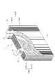
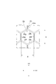
- FIG. 1 is a perspective view showing the overall structure and internal structure of the lead storage battery according to the embodiment.
- FIG. 2 is a perspective view showing a group of plates included in the lead-acid battery of FIG.
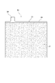
- FIG. 3 is a front view showing an electrode plate included in the electrode plate group of FIG. 2.
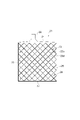
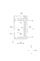
- FIG. 4 is a front view showing an example current collector.
- FIG. 5 is a partially enlarged view of the current collector shown in FIG.
- FIG. 6 is a front view showing a current collector of another example.
- FIG. 7 is a partially enlarged view of the current collector shown in FIG.
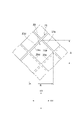
- FIG. 8 is a front view showing a current collector of another example.
- FIG. 9 is a partially enlarged view of the current collector shown in FIG.
- FIG. 10 is a front view showing a current collector of another example.
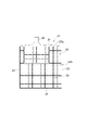
- FIG. 11 is a front view showing the current collector of Comparative Example 1.
- FIG. 12 is a partially enlarged view of the current collector shown in FIG.
- FIG. 13 is a front view showing a simulation result of the current collector of the first embodiment.
- FIG. 14 is a front view showing a simulation result of the current collector of the second embodiment.
- FIG. 15 is a front view showing a simulation result of the current collector of the third embodiment.
- FIG. 16 is a front view showing a simulation result of the current collector of the fourth embodiment.
- FIG. 17 is a front view showing a simulation result of the current collector of Comparative Example 1.
- FIG. 18 is a graph showing the measurement results of the average voltage drop of Examples 1 to 4 and Comparative Example 1.
- FIG. 19 is a front view showing a current collector of another example.
- the vertical direction refers to the vertical direction in the lead storage battery.
- a or B may include either A or B, and may include both.
- the lead-acid battery 1 includes an electric tank 2 having an open upper surface and a lid 3 for closing the opening of the electric tank 2.
- the battery case 2 and the lid 3 are made of polypropylene, for example.
- the lid 3 is provided with a positive electrode terminal 4, a negative electrode terminal 5, and a liquid port plug 6 for closing the liquid injection port provided in the lid 3.
- Electrode plate group 7 Inside the battery case 2, there are a electrode plate group 7, a positive electrode column (not shown) connecting the electrode plate group 7 to the positive electrode terminal 4, and a negative electrode column 8 connecting the electrode plate group 7 to the negative electrode terminal 5.
- an electrolytic solution (not shown) such as dilute sulfuric acid.
- the electrode plate group 7 is configured by laminating a plurality of positive electrode plates 9 and a plurality of negative electrode plates 10 via a separator 11.
- the positive electrode plate 9 is the electrode plate 20 on the positive electrode side
- the negative electrode plate 10 is the electrode plate 20 on the negative electrode side.
- the positive electrode plate 9 and the negative electrode plate 10 are different from the electrode plate on the positive electrode side and the electrode plate of the negative electrode plate, they basically have the same configuration.
- the electrode plate 20 will be collectively described.
- the electrode plate 20 has a current collector (lattice) 21 and an active material (electrode material) 22 attached to the current collector 21. That is, the positive electrode plate 9 has a positive electrode current collector (positive electrode lattice body) 12 and a positive electrode active material (positive electrode material) 13 attached to the positive electrode current collector 12.
- the negative electrode plate 10 has a negative electrode current collector (negative electrode lattice body) 14 and a negative electrode active material (negative electrode material) 15 attached to the negative electrode current collector 14.
- the current collector 21 is made of a lead alloy.
- the lead alloy may be an alloy containing tin, calcium, antimony, selenium, silver, bismuth and the like in addition to lead, and specifically, for example, an alloy containing lead, tin and calcium (Pb-Sn). -Ca-based alloy).
- the electrode plate group 7 has a structure in which a plurality of positive electrode plates 9 and a plurality of negative electrode plates 10 are alternately laminated in a direction substantially parallel to the opening surface of the electric tank 2 via a separator 11. That is, the positive electrode plate 9 and the negative electrode plate 10 are arranged so that their main surfaces extend in the direction perpendicular to the opening surface of the battery case 2.
- the selvage portions 28 of the positive electrode current collectors 12 in the plurality of positive electrode plates 9 are collectively welded by the positive electrode side strap 16.
- the ears 28 of each of the negative electrode current collectors 14 in the plurality of negative electrode plates 10 are collectively welded by the negative electrode side strap 17.
- the positive electrode side strap 16 and the negative electrode side strap 17 are connected to the positive electrode terminal 4 and the negative electrode terminal 5 via the positive electrode column and the negative electrode column 8, respectively.
- the separator 11 has a function of separating the positive electrode plate 9 and the negative electrode plate 10.
- the separator 11 has microporous so that the electrolytic solution (dilute sulfuric acid) can pass through.
- the separator 11 is made of a microporous resin sheet. Examples of the resin used for the separator 11 include polyolefin.
- the electric tank 2 is a container for accommodating the electrode plate group 7.
- the inside of the battery case 2 is divided into a plurality of sections by a plurality of partition walls (not shown), and a plurality of cell chambers (not shown) are formed.
- the cell chamber is a space in which the electrode plate group 7 is inserted.
- the electrode plate group 7 is also called a cell, and has an electromotive force of 2V.
- the number of cell chambers is not limited to six.
- a plurality of saddles (not shown) extending along the direction in which the plurality of cell chambers are arranged may be formed on the bottom surface of the electric tank 2. in this case.
- the electrode plate group 7 is placed on the saddle or is arranged above the saddle at a distance.
- the current collector 21 includes a grid portion 23, a first support portion 24, a second support portion 25, a third support portion 26, a fourth support portion 27, and ears. It has a portion 28 and.
- the grid portion 23 is a portion that holds the active material 22.
- the lattice portion 23 is formed in a lattice shape (net shape) in order to hold the active material 22.
- a plurality of openings 29 are formed in the lattice portion 23.
- the first support portion 24 extends in the first direction D1.
- the first support portion 24 is provided at one end of the grid portion 23 in the second direction D2 orthogonal to the first direction D1.
- the first support portion 24 supports the grid portion 23 from one end side in the second direction D2.
- the shape of the first support portion 24 is not particularly limited, and is, for example, an elongated flat plate in the first direction D1.
- the second support portion 25 is provided at one end of the grid portion 23 in the first direction D1.
- the second support portion 25 extends from the first support portion 24 on one end side of the grid portion 23 in the first direction D1.
- the second support portion 25 supports the grid portion 23 from one end side in the first direction D1.
- the shape of the second support portion 25 is not particularly limited, and is, for example, an elongated flat plate or rod in the second direction D2.
- the third support portion 26 is provided at the other end of the grid portion 23 in the first direction D1 (the side opposite to the second support portion 25).
- the third support portion 26 extends from the first support portion 24 on the other end side of the grid portion 23 in the first direction D1.
- the third support portion 26 supports the grid portion 23 from the other end side in the first direction D1.
- the shape of the third support portion 26 is not particularly limited, and is, for example, an elongated flat plate or rod in the second direction D2.
- the fourth support portion 27 extends in the first direction D1.
- the fourth support portion 27 is provided at the other end of the grid portion 23 in the second direction D2 (the side opposite to the first support portion 24).
- the fourth support portion 27 supports the grid portion 23 from the other end side in the second direction D2.
- the shape of the fourth support portion 27 is not particularly limited, and is, for example, an elongated flat plate or rod in the first direction D1. Both ends of the fourth support portion 27 are connected to the second support portion 25 and the third support portion 26. That is, each of the second support portion 25 and the third support portion 26 connects the first support portion 24 and the fourth support portion 27.
- the selvage portion 28 protrudes from the first support portion 24 on the side opposite to the grid portion 23 in the second direction D2.
- the first support unit 24 also functions as a current collector unit. Therefore, in front view, the area of the first support portion 24 is larger than the area of each of the second support portion 25, the third support portion 26, and the fourth support portion 27 from the viewpoint of improving the current collection efficiency. Is preferable.
- the current collector 21 may not have the fourth support portion 27, and may have another support portion other than the fourth support portion 27.
- the second support portion 25 and the third support portion 26 may extend in a straight line from the first support portion 24 to the fourth support portion 27, may be bent and extended, or may be curved. ..
- the second support portion 25 and the third support portion 26 may extend in the second direction D2, for example.
- the second support portion 25 and the third support portion 26 may, for example, move from the first support portion 24 to the fourth support portion 27. It may extend to spread out from each other and then extend in the second direction D2 and be connected to the fourth support portion 27.
- Examples of the current collector 21 include a punching lattice body in which a plurality of openings 29 of the lattice portion 23 are formed by punching, a cast lattice body in which a plurality of openings 29 of the lattice portion 23 are formed by casting, and the like.
- the current collector 21 will be described as a punching grid.
- the first support portion 24 and the fourth support portion 27 extend in parallel with the first direction D1, and the second support portion 25 and the third support portion 26 extend. It extends parallel to the second direction D2.
- a plurality of rectangular openings 29 are formed in the lattice portion 23. That is, the opening 29 has a rectangular shape having a pair of first sides 29a extending in the first direction D1 and a pair of second sides 29b extending in the second direction D2 and connected to the pair of first sides 29a. It is formed. More specifically, the grid portion 23 has a plurality of first bone portions 23a extending in the first direction D1 and a plurality of second bone portions 23b extending in the second direction D2.
- Both ends of the plurality of first bone portions 23a and the plurality of second bone portions 23b are connected to the first support portion 24, the second support portion 25, the third support portion 26, or the fourth support portion 27.
- the plurality of first bone portions 23a and the plurality of second bone portions 23b form a plurality of rectangular openings 29 having a pair of first side 29a and a pair of second side 29b.
- the rectangular shape includes both a square shape and a rectangular shape. Of the plurality of openings 29, the openings 29 adjacent to the first support portion 24, the second support portion 25, the third support portion 26, or the fourth support portion 27 do not have such a rectangular shape. May be good.
- the first support portion 24 and the fourth support portion 27 extend in parallel with the first direction D1, and the second support portion 25 and the third support portion 26 extend. It extends parallel to the second direction D2.
- a plurality of diamond-shaped openings 29 are formed in the lattice portion 23. That is, the opening 29 is connected to the pair of first sides 29c extending in the direction inclined in the first direction D1 and the second direction D2 and the pair of first sides 29c extending in the direction intersecting the pair of first sides 29c. It is formed in a diamond shape having a pair of second sides 29d. The pair of second sides 29d extends in the direction opposite to the pair of first sides 29c with respect to the first direction D1 and the second direction D2.
- the lattice portion 23 extends in a direction inclined in the first direction D1 and the second direction D2, and a plurality of third bone portions 23c extending in the direction inclined in the first direction D1 and the second direction D2. It also has a plurality of fourth bone portions 23d extending in a direction intersecting the plurality of third bone portions 23c. Both ends of the plurality of third bone portions 23c and the plurality of fourth bone portions 23d are connected to the first support portion 24, the second support portion 25, the third support portion 26, or the fourth support portion 27. There is.
- a plurality of rhombic openings 29 having a pair of first side 29c and a pair of second side 29d are formed by the plurality of third bone portions 23c and the plurality of fourth bone portions 23d.
- This rhombus includes both a rhombus with right-angled corners and a rhombus without right-angled corners.
- the openings 29 adjacent to the first support portion 24, the second support portion 25, the third support portion 26, or the fourth support portion 27 do not have such a diamond shape. May be good.
- the first support portion 24 and the fourth support portion 27 extend in parallel with the first direction D1, and the second support portion 25 and the third support portion 26 extend. It extends parallel to the second direction D2.
- a plurality of hexagonal openings 29 are formed in a honeycomb shape in the lattice portion 23. More specifically, the lattice portion 23 has a honeycomb bone portion 23e extending in a honeycomb shape. The end portion of the honeycomb bone portion 23e is connected to the first support portion 24, the fourth support portion 27, the second support portion 25, or the third support portion 26.
- a plurality of hexagonal openings 29 are formed in a honeycomb shape by the honeycomb bone portion 23e. Of the plurality of openings 29, the openings 29 adjacent to the first support portion 24, the fourth support portion 27, the second support portion 25, or the third support portion 26 do not have such a hexagonal shape. May be good.
- the first support portion 24 and the fourth support portion 27 extend in parallel with the first direction D1, and the second support portion 25 and the third support portion 26 are the first. After extending from the support portion 24 toward the fourth support portion 27 in a direction away from each other, it extends in parallel with the second direction D2 and is connected to the fourth support portion 27.
- a plurality of hexagonal openings 29 are formed in a honeycomb shape in the lattice portion 23. More specifically, the lattice portion 23 has a honeycomb bone portion 23f extending in a honeycomb shape. The end portion of the honeycomb bone portion 23f is connected to the first support portion 24, the second support portion 25, the third support portion 26, or the fourth support portion 27.
- a plurality of hexagonal openings 29 are formed in a honeycomb shape by the honeycomb bone portion 23f.
- the hexagonal opening 29 is formed from the first side 29e and the second side 29f extending parallel to each other in the second direction D2, and the tip of the first side 29e and the second side 29f on the first support portion 24 side (upper side).
- the third side 29g and the fourth side 29h extending in the direction close to each other and joining each other, and the tip of the fourth support portion 27 side (lower side) of the first side 29e and the second side 29f extend in the direction close to each other. It has six sides, a fifth side 29i and a sixth side 29j, which are joined to each other.
- This hexagonal shape includes a hexagonal shape in which the length of each side and the angle of each side are all the same, and a hexagonal shape in which at least one of the lengths of each side or at least one of the angles of each side is different.
- the openings 29 adjacent to the first support portion 24, the second support portion 25, the third support portion 26, or the fourth support portion 27 do not have such a hexagonal shape. May be good.
- the length A of the opening 29 in the first direction D1 is the length of the opening 29 in the first direction D1
- the length B is the maximum length of the opening 29 in the second direction D2.
- the length A of the opening 29 is the length of the second side 29b
- the length B of the opening 29 is the length of the first side 29a.
- the length A of the opening 29 is the first side 29c from the junction on the first support portion 24 side (upper side) between the first side 29c and the second side 29d.
- the length B to the junction of the second side 29d and the fourth support portion 27 side (lower side), and the length B of the opening 29 is the second support portion between the first side 29c and the second side 29d. It is the length from the junction on the 25 side (left side) to the junction on the third support portion 26 side (right side) between the first side 29c and the second side 29d.
- the length A of the opening 29 extends from the junction between the third side 29g and the fourth side 29h to the junction between the fifth side 29i and the sixth side 29j.
- the length B of the opening 29 is the length from the first side 29e to the second side 29f.
- the ratio (A / B) of the length A to the length B is 0.5 or more and 2.5 for the opening 29 having the largest sum (A + B) of the length A and the length B among the plurality of openings 29. It is as follows.
- the A / B is preferably 0.6 or more, preferably 0.65 or more, 0.7 or more, 0.75 or more, and 0. 8 or more, or 0.85 or more is preferable.
- the A / B is 2.0 or less, 1.5 or less, 1.25 or less, 1.2 or less, 1.15 or less, It is preferably 1.1 or less, or 1.05 or less.
- the A / B is 0.6 or more and 2.0 or less, 0.65 or more and 1.5 or less, 0.7 or more and 2.0. Below, 0.75 or more and 1.5 or less, 0.8 or more and 1.25 or less, 0.85 or more and 1.2 or less, 0.85 or more and 1.15 or less, 0.85 or more and 1.1 or less, or 0. It is preferably 85 or more and 1.05 or less.
- the current collector 21 shown in FIGS. 4 and 5 is the current collector of the first embodiment
- the current collector 21 shown in FIGS. 6 and 7 is the current collector of the second embodiment
- FIGS. 8 and 9 are used.
- the current collector 21 shown in FIG. 10 was used as the current collector of Example 3
- the current collector 21 shown in FIG. 10 was used as the current collector of Example 4.
- a plurality of square openings 29 were formed by nine first bone portions 23a and nine second bone portions 23b. Further, the ratio (A / B) of the length A to the length B of the opening 29 having the largest sum (A + B) of the length A and the length B was set to 1.000.
- a plurality of rhombic openings 29 were formed by 13 third bone portions 23c and 13 fourth bone portions 23d.
- the opening 29 has a rhombic shape with right-angled corners. Further, the ratio (A / B) of the length A to the length B of the opening 29 having the largest sum (A + B) of the length A and the length B was set to 1.000.
- a plurality of hexagonal openings 29 were formed by the honeycomb bone portions 23e. Hexagonal shape in which the length of each side and the angle of each side are all the same. Also, the ratio of length A to length B (A / B) of the opening 29 having the largest sum (A + B) of length A and length B. was set to 0.866.
- a plurality of hexagonal openings 29 were formed by the honeycomb bone portion 23f. Hexagonal shape in which the length of each side and the angle of each side are all the same. Also, the ratio of length A to length B (A / B) of the opening 29 having the largest sum (A + B) of length A and length B. was set to 0.866.
- the current collector 121 shown in FIGS. 11 and 12 was used as the current collector of Comparative Example 1.
- the first support portion 124 and the fourth support portion 127 extend in parallel to the first direction D1, similarly to the current collector 21 of the first embodiment.
- the second support portion 125 and the third support portion 126 extend in parallel with the second direction D2, and the selvage portion 128 protrudes from the first support portion 124.
- the lattice portion 123 has a pair of first sides extending in the first direction D1 by six first bone portions 123a extending in the first direction D1 and ten second bone portions 123b extending in the second direction D2.
- a plurality of rectangular openings 129 having a 129a and a pair of second sides 129b extending in the second direction D2 are formed.
- the first side 129a was all the same, but the second side 129b was increased from the first support portion 124 side to the second support portion 125 side. That is, it is assumed that the opening 129 on the side of the second support portion 125 has the largest second side 129b.
- the ratio (A / B) of the length A to the length B of the opening 129 having the largest sum (A + B) of the length A and the length B was set to 3.078.
- Example 1 is shown in FIG. 13
- the simulation result of Example 2 is shown in FIG. 14
- the simulation result of Example 3 is shown in FIG. 15, and the simulation result of Example 4 is shown in FIG.
- the simulation result of No. 1 is shown in FIG. In FIGS. 13 to 17, the four recesses formed in the fourth support portion correspond to the four saddles formed in the bottom surface of the electric tank 2.
- the current collector 21 includes the fourth support portion 27 and the second support portion 25 located on both sides of the first support portion 24.
- the A / B of the opening 29 having the largest sum of the length A and the length B is 2.5 or less, the irregular bending of the current collector 21 is suppressed. As a result, it is possible to suppress the dropping of the active material 22 from the current collector 21.
- the A / B of the opening 29 having the largest sum of the length A and the length B is 0.5 or more, it is possible to prevent the opening 29 from becoming too small. As a result, the weight of the current collector 21 can be reduced and the amount of the active material 22 adhered to the current collector 22 can be increased.
- the plurality of openings 29 are formed in a honeycomb shape, so that the rigidity of the lattice portion 23 is increased. Thereby, the bending of the current collector 21 can be suppressed. Further, since the opening 29 is formed in a rectangular shape, the current collector 21 can be easily manufactured. Further, since the opening 29 is formed in a diamond shape, the current collector 21 can be easily manufactured.
- the rigidity of the grid portion 23 is increased by providing the third support portion 26. Thereby, the bending of the current collector 21 can be suppressed.
- the lead storage battery 1 according to the present embodiment includes the above-mentioned current collector 21, irregular bending of the current collector 21 can be suppressed, and the active material 22 can be suppressed from falling off from the current collector 21. can. As a result, the life of the lead storage battery 1 can be extended.
- the current collector 21 of the positive electrode plate 9 is more likely to extend in the vertical direction of the electric tank 2 due to repeated charging and discharging and the passage of time than the current collector 21 of the negative electrode plate 10, at least the positive electrode plate 9 is carried out.
- the current collector 21 in the form it is possible to effectively suppress the dropping of the active material from the current collector 21 of the lead storage battery 1 as a whole.
- the present invention is not limited to the above embodiment, and can be appropriately modified as long as it does not deviate from the gist of the present invention.
- the thickness of the grid portion may be the same, or part or all may be different.
- the portion 23g in the vicinity of the selvage portion of the grid portion 23A may be formed thicker than the other portion 23h of the grid portion 23A.
- the electricity collected by the current collector 21A is output from the first support portion 24 through the selvage portion 28. Therefore, the current collecting efficiency of the current collector 21A can be improved by forming the portion 23g in the vicinity of the selvage portion of the grid portion 23A thicker than the other portion 23h of the grid portion 23A.
- the thickness may be gradually increased from the other portion 23h of the grid portion 23A toward the portion 23g near the selvage portion of the grid portion 23A, and the other portion 23h of the grid portion 23A and the grid portion 23A may be gradually thickened.
- the thickness may change stepwise with the portion 23 g in the vicinity of the ear portion.
- the specific shapes of the lattice portion and the opening and the like have been described, but the shapes of the lattice portion and the opening and the like can be changed as appropriate.
- the opening may be triangular.
- the positive electrode current collector and the negative electrode current collector have been described as having basically the same configuration, but they may have different configurations from each other.
- the positive electrode current collector may have the above-mentioned current collector configuration
- the negative electrode current collector may have a different configuration from the above-mentioned current collector.
- Electrode plate group 8 ... Negative electrode pillar, 9 ... Positive electrode plate, 10 ... Negative electrode plate , 11 ... Separator, 12 ... Positive electrode current collector, 13 ... Positive electrode active material, 14 ... Negative electrode current collector, 15 ... Negative electrode active material, 16 ... Positive electrode side strap, 17 ... Negative electrode side strap, 20 ... Electrode plate, 21 ... Collector, 21A ... Collector, 22 ... Active material, 23 ... Lattice, 23A ... Lattice, 23a ... First bone, 23b ... Second bone, 23c ...
- lattice part 123a ... first bone Part, 123b ... Second bone part, 124 ... First support part, 125 ... Second support part, 126 ... Third support part, 127 ... Fourth support part, 128 ... Ear part, 129 ... Opening, 129a ... First Side 129b ... Second side, D1 ... First direction, D2 ... Second direction.
Landscapes
- Chemical & Material Sciences (AREA)
- Chemical Kinetics & Catalysis (AREA)
- Electrochemistry (AREA)
- General Chemical & Material Sciences (AREA)
- Cell Electrode Carriers And Collectors (AREA)
Abstract
集電体は、複数の開口が形成された格子部と、格子部の一端に設けられて第一方向に延びる第一支持部と、第一方向における格子部の両側に位置して第一支持部から延びる第二支持部及び第三支持部と、を備え、第一方向における開口の長さをA、第一方向と直交する第二方向における開口の長さをBとした場合、複数の開口のうち、A+Bが最も大きい開口のA/Bが、0.5以上2.5以下である。
Description
本発明は、集電体及び鉛蓄電池に関する。
一般に、鉛蓄電池は、集電体に活物質が充填された複数の電極板を備える極板群が電槽に収容されて構成されている。極板群は、電極板である正極板と負極板とがセパレータを介して交互に積層され、正極板及び負極板の耳部が極性毎にストラップに集合溶接され、ストラップにセル間接続部又は極柱が接続されて、構成されている。特許文献1には、鉛合金シートをエキスパンド加工して展開することで、上枠骨と下枠骨との間に網目状の格子部が形成されたエキスパンド集電体が記載されている。
ところで、鉛蓄電池では、電圧特性を向上させるとともに、集電体の鉛量を減らして軽量化するために、特許文献1に記載されたエキスパンド集電体ではなく、パンチング加工、鋳造等により格子部を形成した集電体を用いることがある。このような集電体では、特許文献1に記載されたエキスパンド集電体とは異なり、格子部の両側に一対の横枠骨が設けられている。このような一対の横枠骨は、電槽の上下方向における集電体の伸びを阻害するものとなる。
鉛蓄電池では、充放電の繰り返しにより電槽の上下方向に集電体が伸びる。また、時間の経過によっても、集電体が電槽の上下方向に伸びる。このため、一対の横枠骨により電槽の上下方向における集電体の伸びが阻害されると、集電体が不規則に撓んで集電体から活物質が脱落し易くなる。その結果、鉛蓄電池の寿命が短くなる。
そこで、本発明の一側面は、集電体の不規則な撓みを抑制して集電体からの活物質の脱落を抑制することができる集電体及び鉛蓄電池を提供することを課題とする。
本発明者は、上記課題について鋭意研究した結果、格子部に形成された開口の形状を所定の条件にすることで、集電体の不規則な撓みを抑制して集電体からの活物質の脱落を抑制することができるとの知見を得た。本発明の一側面は、当該知見に基づいてなされたものである。
本発明の一側面に係る集電体は、複数の開口が形成された格子部と、格子部の一端に設けられて第一方向に延びる第一支持部と、第一方向における格子部の両側に位置して第一支持部から延びる第二支持部及び第三支持部と、を備え、第一方向における開口の長さをA、第一方向と直交する第二方向における開口の長さをBとした場合、複数の開口のうち、A+Bが最も大きい開口のA/Bが、0.5以上2.5以下である。
この集電体では、第一支持部の両側に位置する第二支持部及び第三支持部を備える。しかしながら、長さAと長さBの和が最も大きい開口のA/Bが2.5以下であるため、集電体の不規則な撓みが抑制される。これにより、集電体からの活物質の脱落を抑制することができる。また、長さAと長さBの和が最も大きい開口のA/Bが0.5以上であるため、開口が小さくなり過ぎるのを抑制することができる。これにより、集電体の軽量化を図ることができるとともに、活物質の付着量の増加を図ることができる。
複数の開口は、ハニカム状に形成されていてもよい。この集電体では、複数の開口がハニカム状に形成されていることで、格子部の剛性が高くなる。これにより、集電体の撓みを抑制することができる。
開口は、第一方向に延びる一対の第一辺と、第二方向に延びて一対の第一辺に接続される一対の第二辺と、を有する矩形状に形成されていてもよい。この集電体では、開口が矩形状に形成されていることで、集電体を容易に製造することができる。
開口は、第一方向及び第二方向に傾斜する方向に延びる一対の第一辺と、一対の第一辺と交差する方向に延びて一対の第一辺に接続される一対の第二辺と、を有する菱形状に形成されていてもよい。この集電体では、開口が菱形状に形成されていることで、集電体を容易に製造することができる。
格子部の第一支持部とは反対側の他端に設けられて第一方向に延びる第四支持部を更に備えてもよい。この集電体では、第四支持部を備えることで、格子部の剛性が高くなる。これにより、集電体の撓みを抑制することができる。
第一支持部から格子部とは反対側に突出して設けられた耳部を更に備え、格子部の耳部の近傍の部分は、格子部のそれ以外の部分よりも太く形成されていてもよい。この集電体では、格子部の耳部の近傍の部分が、格子部のそれ以外の部分よりも太く形成されていることで、集電体の集電効率を高めることができる。
本発明の一側面に係る鉛蓄電池は、上記の何れかの集電体を備える。この鉛蓄電池では、上記の何れかの集電体を備えるため、集電体の不規則な撓みが抑制されて、集電体からの活物質の脱落を抑制することができる。これにより、鉛蓄電池の長寿命化を図ることができる。
上記の集電体と、集電体に付着した活物質と、を有する正極板を備えてもよい。正極板の集電体は、負極板の集電体よりも、充放電の繰り返し及び時間の経過により電槽の上下方向に伸び易いため、少なくとも正極板が上記の集電体を有することで、鉛蓄電池全体としての集電体からの活物質の脱落を効果的に抑制することができる。
不規則な撓みを抑制して集電体からの活物質の脱落を抑制することができる。
以下、図面を参照して、本発明の一側面に係る集電体及び鉛蓄電池の実施形態について説明する。なお、全図中、同一又は相当部分には同一符号を付すこととする。また、上下の方向は、鉛蓄電池における上下の方向をいう。また、「A又はB」とは、A及びBのどちらか一方を含んでいればよく、両方とも含んでいてもよい。
<鉛蓄電池>
図1に示すように、鉛蓄電池1は、上面が開口している電槽2と、電槽2の開口を閉じる蓋3とを備えている。電槽2及び蓋3は、例えばポリプロピレンで形成されている。蓋3には、正極端子4と、負極端子5と、蓋3に設けられた注液口を閉塞する液口栓6と、が設けられている。
図1に示すように、鉛蓄電池1は、上面が開口している電槽2と、電槽2の開口を閉じる蓋3とを備えている。電槽2及び蓋3は、例えばポリプロピレンで形成されている。蓋3には、正極端子4と、負極端子5と、蓋3に設けられた注液口を閉塞する液口栓6と、が設けられている。
電槽2の内部には、極板群7と、極板群7を正極端子4に接続する正極柱(図示せず)と、極板群7を負極端子5に接続する負極柱8と、希硫酸等の電解液(図示せず)とが収容されている。
図2に示すように、極板群7は、複数の正極板9と複数の負極板10とがセパレータ11を介して積層されて構成されている。
正極板9は、正極側の電極板20であり、負極板10は、負極側の電極板20である。正極板9と負極板10とは、正極側の電極板と負極板の電極板との違いはあるものの、基本的に同じ構成をしているため、特に分けて説明する場合を除き、これらを電極板20として纏めて説明する。
図2及び図3に示すように、電極板20は、集電体(格子体)21と、集電体21に付着した活物質(電極材)22と、を有する。つまり、正極板9は、正極集電体(正極格子体)12と、正極集電体12に付着した正極活物質(正極材)13と、を有する。負極板10は、負極集電体(負極格子体)14と、負極集電体14に付着した負極活物質(負極材)15と、を有する。集電体21は、鉛合金で形成されている。鉛合金は、鉛に加えて、スズ、カルシウム、アンチモン、セレン、銀、ビスマス等を含有する合金であってよく、具体的には、例えば、鉛、スズ及びカルシウムを含有する合金(Pb-Sn-Ca系合金)である。
極板群7は、複数の正極板9と複数の負極板10とが、セパレータ11を介して、電槽2の開口面と略平行方向に交互に積層された構造を有している。すなわち、正極板9及び負極板10は、それらの主面が電槽2の開口面と垂直方向に広がるように配置されている。極板群7において、複数の正極板9における各正極集電体12が有する耳部28同士は、正極側ストラップ16で集合溶接されている。同様に、複数の負極板10における各負極集電体14が有する耳部28同士は、負極側ストラップ17で集合溶接されている。正極側ストラップ16及び負極側ストラップ17は、それぞれ、正極柱及び負極柱8を介して正極端子4及び負極端子5に接続されている。
セパレータ11は、正極板9と負極板10とを分離する機能を有する。セパレータ11は、電解液(希硫酸)が通過できるように微多孔性を有する。セパレータ11は、微多孔性の樹脂製シートにより作製される。セパレータ11に用いられる樹脂としては、例えば、ポリオレフィンが挙げられる。
図1に示すように、電槽2は、極板群7を収容する容器である。電槽2の内部は、複数の隔壁(不図示)によって複数の区画に分割されて、複数のセル室(不図示)が形成されている。セル室は、極板群7が挿入される空間である。極板群7は、単電池とも呼ばれており、起電力は2Vである。自動車用の電装品は、直流電圧12Vを昇圧又は降圧して駆動するため、6個の極板群7を直列に接続して、2V×6=12Vとしている。そのため、鉛蓄電池1を自動車用の電装品として用いる場合、セル室は6個必要となる。なお、鉛蓄電池1を他の用途で用いる場合は、セル室は6個に限定されるものではない。また、電槽2の底面には、複数のセル室が配列される方向に沿って延びる複数の鞍(不図示)が形成されていてもよい。この場合。極板群7は、鞍に載置され、又は鞍の上方に離間して配置されている。
(集電体)
図4~図10に示すように、集電体21は、格子部23と、第一支持部24と、第二支持部25と、第三支持部26と、第四支持部27と、耳部28と、を有している。
図4~図10に示すように、集電体21は、格子部23と、第一支持部24と、第二支持部25と、第三支持部26と、第四支持部27と、耳部28と、を有している。
格子部23は、活物質22を保持する部分である。格子部23は、活物質22を保持するために格子状(網状)に形成されている。格子部23には、複数の開口29が形成されている。
第一支持部24は、第一方向D1に延びている。第一支持部24は、第一方向D1と直交する第二方向D2における格子部23の一端に設けられている。第一支持部24は、第二方向D2における一端側から格子部23を支持する。第一支持部24の形状は、特に限定されるものではなく、例えば、第一方向D1に細長い平板状である。
第二支持部25は、第一方向D1における格子部23の一端に設けられている。第二支持部25は、第一方向D1における格子部23の一端側において、第一支持部24から延びている。第二支持部25は、第一方向D1における一端側から格子部23を支持する。第二支持部25の形状は、特に限定されるものではなく、例えば、第二方向D2に細長い平板状又は棒状である。
第三支持部26は、第一方向D1における格子部23の他端(第二支持部25とは反対側)に設けられている。第三支持部26は、第一方向D1における格子部23の他端側において、第一支持部24から延びている。第三支持部26は、第一方向D1における他端側から格子部23を支持する。第三支持部26の形状は、特に限定されるものではなく、例えば、第二方向D2に細長い平板状又は棒状である。
第四支持部27は、第一方向D1に延びている。第四支持部27は、第二方向D2における格子部23の他端(第一支持部24とは反対側)に設けられている。第四支持部27は、第二方向D2における他端側から格子部23を支持する。第四支持部27の形状は、特に限定されるものではなく、例えば、第一方向D1に細長い平板状又は棒状である。第四支持部27の両端部は、第二支持部25及び第三支持部26に接続されている。つまり、第二支持部25及び第三支持部26のそれぞれは、第一支持部24と第四支持部27とを接続している。
耳部28は、第一支持部24から第二方向D2における格子部23とは反対側に突出している。
第一支持部24は、集電部としても機能する。このため、正面視において、第一支持部24の面積は、集電効率を向上させる観点から、第二支持部25、第三支持部26、及び第四支持部27のそれぞれの面積よりも大きいことが好ましい。なお、集電体21は、第四支持部27を有していなくてもよく、第四支持部27以外に他の支持部を有していてもよい。
第二支持部25及び第三支持部26は、第一支持部24から第四支持部27まで、一直線状に延びていてもよく、屈曲して延びていてもよく、湾曲していてもよい。第二支持部25及び第三支持部26が一直線状に延びている場合、第二支持部25及び第三支持部26は、例えば、第二方向D2に延びるものとすることができる。第二支持部25及び第三支持部26が屈曲して延びている場合、第二支持部25及び第三支持部26は、例えば、第一支持部24から第四支持部27に向けて、互いに広がるように延び、その後、第二方向D2に延びて第四支持部27に接続されるものとすることができる。
集電体21としては、格子部23の複数の開口29がパンチング加工により形成されたパンチング格子体、格子部23の複数の開口29が鋳造により形成された鋳造格子体等が挙げられる。本実施形態では、一例として、集電体21がパンチング格子体であるものとして説明する。
図4及び図5に示す集電体21では、第一支持部24と第四支持部27とが第一方向D1に平行に延びており、第二支持部25と第三支持部26とが第二方向D2に平行に延びている。格子部23には、複数の矩形状の開口29が形成されている。つまり、開口29は、第一方向D1に延びる一対の第一辺29aと、第二方向D2に延びて一対の第一辺29aに接続される一対の第二辺29bと、を有する矩形状に形成されている。より具体的には、格子部23は、第一方向D1に延びる複数の第一骨部23aと、第二方向D2に延びる複数の第二骨部23bと、を有している。複数の第一骨部23a及び複数の第二骨部23bのそれぞれの両端部は、第一支持部24、第二支持部25、第三支持部26、又は第四支持部27に接続されている。そして、複数の第一骨部23a及び複数の第二骨部23bにより、一対の第一辺29a及び一対の第二辺29bを有する複数の矩形状の開口29が形成されている。矩形状には、正方形状及び長方形状の双方が含まれる。なお、複数の開口29のうち、第一支持部24、第二支持部25、第三支持部26、又は第四支持部27に隣接する開口29は、このような矩形状になっていなくてもよい。
図6及び図7に示す集電体21では、第一支持部24と第四支持部27とが第一方向D1に平行に延びており、第二支持部25と第三支持部26とが第二方向D2に平行に延びている。格子部23には、複数の菱形状の開口29が形成されている。つまり、開口29は、第一方向D1及び第二方向D2に傾斜する方向に延びる一対の第一辺29cと、一対の第一辺29cと交差する方向に延びて一対の第一辺29cに接続される一対の第二辺29dと、を有する菱形状に形成されている。一対の第二辺29dは、第一方向D1及び第二方向D2に対して、一対の第一辺29cと逆方向に延びている。より具体的には、格子部23は、第一方向D1及び第二方向D2に傾斜する方向に延びる複数の第三骨部23cと、第一方向D1及び第二方向D2に傾斜する方向に延びるとともに複数の第三骨部23cと交差する方向に延びる複数の第四骨部23dと、を有している。複数の第三骨部23c及び複数の第四骨部23dのそれぞれの両端部は、第一支持部24、第二支持部25、第三支持部26、又は第四支持部27に接続されている。そして、複数の第三骨部23c及び複数の第四骨部23dにより、一対の第一辺29c及び一対の第二辺29dを有する複数の菱形状の開口29が形成されている。この菱形状には、直角の角を有する菱形状及び直角の角を有しない菱形状の双方が含まれる。なお、複数の開口29のうち、第一支持部24、第二支持部25、第三支持部26、又は第四支持部27に隣接する開口29は、このような菱形状になっていなくてもよい。
図8及び図9に示す集電体21では、第一支持部24と第四支持部27とが第一方向D1に平行に延びており、第二支持部25と第三支持部26とが第二方向D2に平行に延びている。そして、格子部23には、複数の六角形状の開口29がハニカム状に形成されている。より具体的には、格子部23は、ハニカム状に延びるハニカム骨部23eを有している。ハニカム骨部23eの端部は、第一支持部24、第四支持部27、第二支持部25、又は第三支持部26に接続されている。そして、ハニカム骨部23eにより、複数の六角形状の開口29がハニカム状に形成されている。なお、複数の開口29のうち、第一支持部24、第四支持部27、第二支持部25、又は第三支持部26に隣接する開口29は、このような六角形状になっていなくてもよい。
図10に示す集電体21では、第一支持部24と第四支持部27とが第一方向D1に平行に延びており、第二支持部25と第三支持部26とが、第一支持部24から第四支持部27に向けて互いに離れる方向に延びた後、第二方向D2に平行に延びて第四支持部27に接続されている。格子部23には、複数の六角形状の開口29がハニカム状に形成されている。より具体的には、格子部23は、ハニカム状に延びるハニカム骨部23fを有している。ハニカム骨部23fの端部は、第一支持部24、第二支持部25、第三支持部26、又は第四支持部27に接続されている。そして、ハニカム骨部23fにより、複数の六角形状の開口29がハニカム状に形成されている。この六角形状の開口29は、第二方向D2に互いに平行に延びる第一辺29e及び第二辺29fと、第一辺29e及び第二辺29fの第一支持部24側(上側)の先端から互いに近接する方向に延びて互いに接合する第三辺29g及び第四辺29hと、第一辺29e及び第二辺29fの第四支持部27側(下側)の先端から互いに近接する方向に延びて互いに接合する第五辺29i及び第六辺29jと、の六辺を有する。この六角形状には、各辺の長さ及び各辺の角度が全て同じ六角形状の他、各辺の長さの少なくとも一つ又は各辺の角度の少なくとも一つが異なる六角形状も含まれる。なお、複数の開口29のうち、第一支持部24、第二支持部25、第三支持部26、又は第四支持部27に隣接する開口29は、このような六角形状になっていなくてもよい。
ここで、第一方向D1における開口29の長さをAとし、第二方向D2における開口29の長さをBとする。長さAは、第一方向D1における開口29の最大長さであり、長さBは、第二方向D2における開口29の最大長さである。図4及び図5に示す集電体21の場合、開口29の長さAは、第二辺29bの長さであり、開口29の長さBは、第一辺29aの長さである。図6及び図7に示す集電体21の場合、開口29の長さAは、第一辺29cと第二辺29dとの第一支持部24側(上側)の接合点から第一辺29cと第二辺29dとの第四支持部27側(下側)の接合点までの長さであり、開口29の長さBは、第一辺29cと第二辺29dとの第二支持部25側(左側)の接合点から第一辺29cと第二辺29dとの第三支持部26側(右側)の接合点までの長さである。図8及び図9に示す集電体21の場合、開口29の長さAは、第三辺29gと第四辺29hとの接合点から第五辺29iと第六辺29jとの接合点までの長さであり、開口29の長さBは、第一辺29eから第二辺29fまでの長さである。
そして、複数の開口29のうち、長さAと長さBの和(A+B)が最も大きい開口29について、長さBに対する長さAの割合(A/B)が0.5以上2.5以下となっている。この場合、不規則な撓みを抑制し、活物質の脱落を抑制できる観点から、A/Bは、0.6以上が好ましく、0.65以上、0.7以上、0.75以上、0.8以上、又は0.85以上が好ましい。また、不規則な撓みを抑制し、活物質の脱落を抑制できる観点から、A/Bは、2.0以下、1.5以下、1.25以下、1.2以下、1.15以下、1.1以下、又は1.05以下が好ましい。また、不規則な撓みを抑制し、活物質の脱落を抑制できる観点から、A/Bは、0.6以上2.0以下、0.65以上1.5以下、0.7以上2.0以下、0.75以上1.5以下、0.8以上1.25以下、0.85以上1.2以下、0.85以上1.15以下、0.85以上1.1以下、又は0.85以上1.05以下が好ましい。
ここで、図4及び図5に示す集電体21を実施例1の集電体とし、図6及び図7に示す集電体21を実施例2の集電体とし、図8及び図9に示す集電体21を実施例3の集電体とし、図10に示す集電体21を実施例4の集電体とした。
実施例1の集電体21(図4及び図5参照)では、9本の第一骨部23a及び9本の第二骨部23bにより複数の正方形状の開口29を形成した。また、長さAと長さBの和(A+B)が最も大きい開口29の、長さBに対する長さAの割合(A/B)を、1.000とした。
実施例2の集電体21(図6及び図7参照)では、13本の第三骨部23c及び13本の第四骨部23dにより複数の菱形状の開口29を形成した。開口29は、直角の角を有する菱形状とした。また、長さAと長さBの和(A+B)が最も大きい開口29の、長さBに対する長さAの割合(A/B)を、1.000とした。
実施例3の集電体21(図8及び図9参照)では、ハニカム骨部23eにより複数の六角形状の開口29を形成した。各辺の長さ及び各辺の角度が全て同じ六角形状また、長さAと長さBの和(A+B)が最も大きい開口29の、長さBに対する長さAの割合(A/B)を、0.866とした。
実施例3の集電体21(図10参照)では、ハニカム骨部23fにより複数の六角形状の開口29を形成した。各辺の長さ及び各辺の角度が全て同じ六角形状また、長さAと長さBの和(A+B)が最も大きい開口29の、長さBに対する長さAの割合(A/B)を、0.866とした。
また、図11及び図12に示す集電体121を比較例1の集電体とした。図11及び図12に示す比較例1の集電体121では、実施例1の集電体21と同様に、第一支持部124と第四支持部127とが第一方向D1に平行に延びており、第二支持部125と第三支持部126とが第二方向D2に平行に延びており、第一支持部124から耳部128が突出している。格子部123には、第一方向D1に延びる6本の第一骨部123aと、第二方向D2に延びる10本の第二骨部123bとにより、第一方向D1に延びる一対の第一辺129aと、第二方向D2に延びる一対の第二辺129bと、を有する複数の長方形状の開口129が形成されている。複数の開口129において、第一辺129aは全て同じとしたが、第二辺129bは、第一支持部124側から第二支持部125側に向かうに従い大きくした。つまり、最も第二支持部125側の開口129が、最も大きい第二辺129bを有するものとした。また、長さAと長さBの和(A+B)が最も大きい開口129の、長さBに対する長さAの割合(A/B)を、3.078とした。
そして、実施例1~4及び比較例1の集電体を用いて、充放電の繰り返し及び時間の経過に伴う集電体の伸びをシミュレーションした。シミュレーションでは、電槽2の底面に4本の鞍が形成されており、これらの鞍に集電体が載置されているものとした。実施例1のシミュレーション結果を図13に示し、実施例2のシミュレーション結果を図14に示し、実施例3のシミュレーション結果を図15に示し、実施例4のシミュレーション結果を図16に示し、比較例1のシミュレーション結果を図17に示す。図13~図17において、第四支持部に形成された4つの凹みは、電槽2の底面に形成された4本の鞍に対応する。
図17に示すように、比較例1の集電体121では、格子部123が大きく不規則に変形した。これに対し、図13~図16に示すように、実施例1~4の集電体21では、比較例1の集電体121に比べて、変形の度合いが小さかった。
また、実施例1~4及び比較例1の集電体を用いて、充放電を繰り返すサイクル試験を行い、サイクル試験前に対するサイクル試験後の平均電圧降下(V)を計測した。計測結果を図18に示す。図18に示すように、比較例1の集電体121では、平均電圧降下が-0.12Vであった。これに対し、実施例1~4の集電体21では、平均電圧降下が-0.08Vと、比較例1の集電体121よりも平均電圧降下が小さかった。
以上説明したように、本実施形態に係る集電体21では、第一支持部24の両側に位置する第四支持部27及び第二支持部25を備える。しかしながら、長さAと長さBの和が最も大きい開口29のA/Bが2.5以下であるため、集電体21の不規則な撓みが抑制される。これにより、集電体21からの活物質22の脱落を抑制することができる。また、長さAと長さBの和が最も大きい開口29のA/Bが0.5以上であるため、開口29が小さくなり過ぎるのを抑制することができる。これにより、集電体21の軽量化を図ることができるとともに、活物質22の付着量の増加を図ることができる。
また、この集電体21では、複数の開口29がハニカム状に形成されていることで、格子部23の剛性が高くなる。これにより、集電体21の撓みを抑制することができる。また、開口29が矩形状に形成されていることで、集電体21を容易に製造することができる。また、開口29が菱形状に形成されていることで、集電体21を容易に製造することができる。
また、この集電体21では、第三支持部26を備えることで、格子部23の剛性が高くなる。これにより、集電体21の撓みを抑制することができる。
本実施形態に係る鉛蓄電池1では、上記の集電体21を備えるため、集電体21の不規則な撓みが抑制されて、集電体21からの活物質22の脱落を抑制することができる。これにより、鉛蓄電池1の長寿命化を図ることができる。
ところで、正極板9の集電体21は、負極板10の集電体21よりも、充放電の繰り返し及び時間の経過により電槽2の上下方向に伸び易いため、少なくとも正極板9が上記実施形態の集電体21を有することで、鉛蓄電池1全体としての集電体21からの活物質の脱落を効果的に抑制することができる。
本発明は、上記実施形態に限定されるものではなく、本発明の趣旨を逸脱しない限り適宜変更が可能である。
例えば、格子部の太さは、全て同じであってもよく、一部又は全部が違っていてもよい。例えば、図19に示す集電体21Aのように、格子部23Aの耳部の近傍の部分23gは、格子部23Aのそれ以外の部分23hよりも太く形成されていてもよい。集電体21Aで集電された電気は、第一支持部24から耳部28を通って出力される。このため、格子部23Aの耳部の近傍の部分23gが、格子部23Aのそれ以外の部分23hよりも太く形成されていることで、集電体21Aの集電効率を高めることができる。この場合、格子部23Aのそれ以外の部分23hから格子部23Aの耳部の近傍の部分23gに向けて徐々に太くなっていてもよく、格子部23Aのそれ以外の部分23hと格子部23Aの耳部の近傍の部分23gとの間で段状に太さが変わってもよい。
また、上記実施形態では、格子部及び開口等の具体的な形状について説明したが、格子部及び開口等の形状は、適宜変更することができる。例えば、開口は、三角形状としてもよい。
また、上記実施形態では、正極集電体と負極集電体とは、基本的に同じ構成をしているものとして説明したが、互いに異なる構成をしていてもよい。例えば、正極集電体が、上述した集電体の構成をしており、負極集電体が、上述した集電体とは異なる構成をしていてもよい。
1…鉛蓄電池、2…電槽、3…蓋、4…正極端子、5…負極端子、6…液口栓、7…極板群、8…負極柱、9…正極板、10…負極板、11…セパレータ、12…正極集電体、13…正極活物質、14…負極集電体、15…負極活物質、16…正極側ストラップ、17…負極側ストラップ、20…電極板、21…集電体、21A…集電体、22…活物質、23…格子部、23A…格子部、23a…第一骨部、23b…第二骨部、23c…第三骨部、23d…第四骨部、23e…ハニカム骨部、23f…ハニカム骨部、23g…格子部の耳部の近傍の部分、23h…格子部のそれ以外の部分、24…第一支持部、25…第二支持部、26…第三支持部、27…第四支持部、28…耳部、29…開口、29a…第一辺、29b…第二辺、29c…第一辺、29d…第二辺、29e…第一辺、29f…第二辺、29g…第三辺、29h…第四辺、29i…第五辺、29j…第六辺、121…集電体、123…格子部、123a…第一骨部、123b…第二骨部、124…第一支持部、125…第二支持部、126…第三支持部、127…第四支持部、128…耳部、129…開口、129a…第一辺、129b…第二辺、D1…第一方向、D2…第二方向。
Claims (8)
- 複数の開口が形成された格子部と、
前記格子部の一端に設けられて第一方向に延びる第一支持部と、
前記第一方向における前記格子部の両側に位置して前記第一支持部から延びる第二支持部及び第三支持部と、を備え、
前記第一方向における前記開口の長さをA、前記第一方向と直交する第二方向における前記開口の長さをBとした場合、複数の前記開口のうち、A+Bが最も大きい前記開口のA/Bが、0.5以上2.5以下である、
集電体。 - 前記複数の開口は、ハニカム状に形成されている、
請求項1に記載の集電体。 - 前記開口は、前記第一方向に延びる一対の第一辺と、前記第二方向に延びて前記一対の第一辺に接続される一対の第二辺と、を有する矩形状に形成されている、
請求項1に記載の集電体。 - 前記開口は、前記第一方向及び前記第二方向に傾斜する方向に延びる一対の第一辺と、前記一対の第一辺と交差する方向に延びて前記一対の第一辺に接続される一対の第二辺と、を有する菱形状に形成されている、
請求項1に記載の集電体。 - 前記格子部の前記第一支持部とは反対側の他端に設けられて前記第一方向に延びる第四支持部を更に備える、
請求項1~4の何れか一項に記載の集電体。 - 前記第一支持部から前記格子部とは反対側に突出して設けられた耳部を更に備え、
前記格子部の前記耳部の近傍の部分は、前記格子部のそれ以外の部分よりも太く形成されている、
請求項1~5の何れか一項に記載の集電体。 - 請求項1~6の何れか一項に記載の集電体を備える鉛蓄電池。
- 前記集電体と、前記集電体に付着した活物質と、を有する正極板を備える、
請求項7に記載の鉛蓄電池。
Priority Applications (1)
| Application Number | Priority Date | Filing Date | Title |
|---|---|---|---|
| PCT/JP2020/037703 WO2022074707A1 (ja) | 2020-10-05 | 2020-10-05 | 集電体及び鉛蓄電池 |
Applications Claiming Priority (1)
| Application Number | Priority Date | Filing Date | Title |
|---|---|---|---|
| PCT/JP2020/037703 WO2022074707A1 (ja) | 2020-10-05 | 2020-10-05 | 集電体及び鉛蓄電池 |
Publications (1)
| Publication Number | Publication Date |
|---|---|
| WO2022074707A1 true WO2022074707A1 (ja) | 2022-04-14 |
Family
ID=81126758
Family Applications (1)
| Application Number | Title | Priority Date | Filing Date |
|---|---|---|---|
| PCT/JP2020/037703 Ceased WO2022074707A1 (ja) | 2020-10-05 | 2020-10-05 | 集電体及び鉛蓄電池 |
Country Status (1)
| Country | Link |
|---|---|
| WO (1) | WO2022074707A1 (ja) |
Citations (4)
| Publication number | Priority date | Publication date | Assignee | Title |
|---|---|---|---|---|
| JPS63184562U (ja) * | 1987-05-20 | 1988-11-28 | ||
| JP2000311693A (ja) * | 1999-04-16 | 2000-11-07 | Samsung Sdi Co Ltd | 集電体および電極並びにこれらを用いた2次電池 |
| JP2001332251A (ja) * | 2000-05-25 | 2001-11-30 | Shin Kobe Electric Mach Co Ltd | 鉛蓄電池用極板およびその製造方法 |
| JP2010520607A (ja) * | 2007-03-02 | 2010-06-10 | ジョンソン コントロールズ テクノロジー カンパニー | 電池用負極グリッド |
-
2020
- 2020-10-05 WO PCT/JP2020/037703 patent/WO2022074707A1/ja not_active Ceased
Patent Citations (4)
| Publication number | Priority date | Publication date | Assignee | Title |
|---|---|---|---|---|
| JPS63184562U (ja) * | 1987-05-20 | 1988-11-28 | ||
| JP2000311693A (ja) * | 1999-04-16 | 2000-11-07 | Samsung Sdi Co Ltd | 集電体および電極並びにこれらを用いた2次電池 |
| JP2001332251A (ja) * | 2000-05-25 | 2001-11-30 | Shin Kobe Electric Mach Co Ltd | 鉛蓄電池用極板およびその製造方法 |
| JP2010520607A (ja) * | 2007-03-02 | 2010-06-10 | ジョンソン コントロールズ テクノロジー カンパニー | 電池用負極グリッド |
Similar Documents
| Publication | Publication Date | Title |
|---|---|---|
| CA1141431A (en) | Radial grids for lead acid batteries | |
| JP5456254B2 (ja) | 交互配向の構成を有する二次電池パック | |
| US4320183A (en) | Grid for batteries | |
| CN111164809B (zh) | 铅蓄电池用正极板栅以及铅蓄电池 | |
| JPH07105929A (ja) | 鉛蓄電池 | |
| KR101722344B1 (ko) | 조전지 | |
| JP7365014B2 (ja) | 鉛蓄電池 | |
| JP2016533024A (ja) | 電気化学蓄電池の板状バッテリ電極用の格子配列物、および蓄電池 | |
| WO2022074707A1 (ja) | 集電体及び鉛蓄電池 | |
| CN105765760B (zh) | 用于板状电池电极的板栅组件以及蓄电池 | |
| JP5861077B2 (ja) | 鉛蓄電池 | |
| JP6893457B2 (ja) | バイポーラ固体電池の集電板配置構造 | |
| CN107895817B (zh) | 铅蓄电池和集电体 | |
| JPH0551144B2 (ja) | ||
| CN221009102U (zh) | 一种新结构动力电池塑壳 | |
| JPS603489Y2 (ja) | 鉛蓄電池 | |
| JP3838489B2 (ja) | 鉛蓄電池 | |
| JP2000149982A (ja) | 電 池 | |
| JP6778388B2 (ja) | 鉛蓄電池 | |
| US12531277B2 (en) | Lead-acid battery | |
| JPS634369Y2 (ja) | ||
| CN210073936U (zh) | 铅炭蓄电池盖 | |
| CN223093054U (zh) | 一种储能电池Pack包 | |
| CN223023384U (zh) | 一种电池槽及铅蓄电池 | |
| CN110707251A (zh) | 一种环形散热锂电池包组件 |
Legal Events
| Date | Code | Title | Description |
|---|---|---|---|
| 121 | Ep: the epo has been informed by wipo that ep was designated in this application |
Ref document number: 20956656 Country of ref document: EP Kind code of ref document: A1 |
|
| NENP | Non-entry into the national phase |
Ref country code: DE |
|
| 122 | Ep: pct application non-entry in european phase |
Ref document number: 20956656 Country of ref document: EP Kind code of ref document: A1 |
|
| NENP | Non-entry into the national phase |
Ref country code: JP |