WO2022071442A1 - 血中物質濃度測定装置及び血中物質濃度測定方法 - Google Patents
血中物質濃度測定装置及び血中物質濃度測定方法 Download PDFInfo
- Publication number
- WO2022071442A1 WO2022071442A1 PCT/JP2021/035990 JP2021035990W WO2022071442A1 WO 2022071442 A1 WO2022071442 A1 WO 2022071442A1 JP 2021035990 W JP2021035990 W JP 2021035990W WO 2022071442 A1 WO2022071442 A1 WO 2022071442A1
- Authority
- WO
- WIPO (PCT)
- Prior art keywords
- light
- measurement target
- photodetector
- blood
- target portion
- Prior art date
- Legal status (The legal status is an assumption and is not a legal conclusion. Google has not performed a legal analysis and makes no representation as to the accuracy of the status listed.)
- Ceased
Links
Images






Classifications
-
- G—PHYSICS
- G01—MEASURING; TESTING
- G01N—INVESTIGATING OR ANALYSING MATERIALS BY DETERMINING THEIR CHEMICAL OR PHYSICAL PROPERTIES
- G01N21/00—Investigating or analysing materials by the use of optical means, i.e. using sub-millimetre waves, infrared, visible or ultraviolet light
- G01N21/17—Systems in which incident light is modified in accordance with the properties of the material investigated
- G01N21/25—Colour; Spectral properties, i.e. comparison of effect of material on the light at two or more different wavelengths or wavelength bands
- G01N21/31—Investigating relative effect of material at wavelengths characteristic of specific elements or molecules, e.g. atomic absorption spectrometry
- G01N21/35—Investigating relative effect of material at wavelengths characteristic of specific elements or molecules, e.g. atomic absorption spectrometry using infrared light
- G01N21/3577—Investigating relative effect of material at wavelengths characteristic of specific elements or molecules, e.g. atomic absorption spectrometry using infrared light for analysing liquids, e.g. polluted water
-
- A—HUMAN NECESSITIES
- A61—MEDICAL OR VETERINARY SCIENCE; HYGIENE
- A61B—DIAGNOSIS; SURGERY; IDENTIFICATION
- A61B5/00—Measuring for diagnostic purposes; Identification of persons
- A61B5/145—Measuring characteristics of blood in vivo, e.g. gas concentration or pH-value ; Measuring characteristics of body fluids or tissues, e.g. interstitial fluid or cerebral tissue
- A61B5/14532—Measuring characteristics of blood in vivo, e.g. gas concentration or pH-value ; Measuring characteristics of body fluids or tissues, e.g. interstitial fluid or cerebral tissue for measuring glucose, e.g. by tissue impedance measurement
-
- A—HUMAN NECESSITIES
- A61—MEDICAL OR VETERINARY SCIENCE; HYGIENE
- A61B—DIAGNOSIS; SURGERY; IDENTIFICATION
- A61B5/00—Measuring for diagnostic purposes; Identification of persons
- A61B5/145—Measuring characteristics of blood in vivo, e.g. gas concentration or pH-value ; Measuring characteristics of body fluids or tissues, e.g. interstitial fluid or cerebral tissue
- A61B5/1455—Measuring characteristics of blood in vivo, e.g. gas concentration or pH-value ; Measuring characteristics of body fluids or tissues, e.g. interstitial fluid or cerebral tissue using optical sensors, e.g. spectral photometrical oximeters
-
- G—PHYSICS
- G01—MEASURING; TESTING
- G01N—INVESTIGATING OR ANALYSING MATERIALS BY DETERMINING THEIR CHEMICAL OR PHYSICAL PROPERTIES
- G01N21/00—Investigating or analysing materials by the use of optical means, i.e. using sub-millimetre waves, infrared, visible or ultraviolet light
- G01N21/17—Systems in which incident light is modified in accordance with the properties of the material investigated
- G01N21/47—Scattering, i.e. diffuse reflection
- G01N21/4738—Diffuse reflection, e.g. also for testing fluids, fibrous materials
-
- G—PHYSICS
- G01—MEASURING; TESTING
- G01N—INVESTIGATING OR ANALYSING MATERIALS BY DETERMINING THEIR CHEMICAL OR PHYSICAL PROPERTIES
- G01N21/00—Investigating or analysing materials by the use of optical means, i.e. using sub-millimetre waves, infrared, visible or ultraviolet light
- G01N21/17—Systems in which incident light is modified in accordance with the properties of the material investigated
- G01N21/47—Scattering, i.e. diffuse reflection
- G01N21/49—Scattering, i.e. diffuse reflection within a body or fluid
-
- G—PHYSICS
- G01—MEASURING; TESTING
- G01N—INVESTIGATING OR ANALYSING MATERIALS BY DETERMINING THEIR CHEMICAL OR PHYSICAL PROPERTIES
- G01N21/00—Investigating or analysing materials by the use of optical means, i.e. using sub-millimetre waves, infrared, visible or ultraviolet light
- G01N21/17—Systems in which incident light is modified in accordance with the properties of the material investigated
- G01N21/25—Colour; Spectral properties, i.e. comparison of effect of material on the light at two or more different wavelengths or wavelength bands
- G01N21/31—Investigating relative effect of material at wavelengths characteristic of specific elements or molecules, e.g. atomic absorption spectrometry
- G01N21/35—Investigating relative effect of material at wavelengths characteristic of specific elements or molecules, e.g. atomic absorption spectrometry using infrared light
- G01N21/359—Investigating relative effect of material at wavelengths characteristic of specific elements or molecules, e.g. atomic absorption spectrometry using infrared light using near infrared light
Definitions
- the present disclosure relates to an apparatus and method for measuring the concentration of a substance contained in blood flowing in a blood vessel of a living body by a non-invasive measuring method.
- Patent Document 1 irradiates a living body with high-intensity mid-infrared light via a waveguide, and guides the reflected light to a photodetector via a waveguide, thereby making it non-invasive and simple.
- a blood substance concentration measuring device for measuring a blood glucose concentration in the configuration is disclosed.
- the present disclosure has been made in view of the above problems, and is a blood substance concentration measuring device capable of stably performing highly accurate measurement regardless of changes in the state of the measurement target and the irradiation condition of the laser beam. And to provide a method for measuring blood substance concentration.
- the blood substance concentration measuring device is a blood substance concentration measuring device for measuring the concentration of a substance contained in the blood of a living body, and includes a measurement target portion.
- the light detector for detecting the intensity and the first lens between the measurement target portion in the optical path of the reflected light and the light detector are provided, and the said in the optical path from the measurement target portion to the light detector.
- the reflected light propagates in space except for the section passing through the first lens, and the first lens transmits the reflected light to the light detector. It is characterized by forming an image on the top.
- the blood substance concentration measuring device and the blood substance concentration measuring method according to one aspect of the present disclosure, highly accurate measurement is stably performed regardless of changes in the state of the measurement target and the irradiation conditions of the laser beam. be able to.
- FIG. (A) and (b) are enlarged cross-sectional views of part A of FIG. It is a schematic diagram which shows the structure of the light irradiation part 20 in the blood substance concentration measuring apparatus 1. It is a figure for demonstrating the outline of the light-receiving side optical path in the blood substance concentration measuring apparatus 1.
- FIGS. 5 (a) to 5 (d) are diagrams showing the correlation between the measurement result of the glucose concentration by the photodetector and the measurement result of the glucose concentration by the invasive measuring device in FIGS. 5 (a) to 5 (d). be.
- the change in the glucose concentration measured by the optical detector of the blood substance concentration measuring device 1 and the change in the glucose concentration measured by the invasive measuring device were compared in chronological order. It is a figure.
- (A) to (c) show the correlation between the measurement result of the glucose concentration by the photodetector and the measurement result of the glucose concentration by the invasive blood glucose concentration measuring device in FIGS. 7 (a) to 7 (c). It is a figure which shows.
- FIG. 1 It is a schematic diagram of the experimental device which measures the measured value of the glucose concentration by the photodetector by changing the light-receiving angle in the blood substance concentration measuring device 1.
- FIG. 1 is a schematic diagram showing the change of the measured value of glucose concentration when the light receiving angle of the photodetector is changed in the blood substance concentration measuring device 1.
- the change in the measured value of glucose concentration by the optical detector when the length of the light path on the light receiving side is changed in the blood substance concentration measuring device 1, and the measurement of glucose concentration by the invasive measuring device. It is the figure which compared the change of the value in time series.
- FIGS. 10 (a) and 10 (b) are diagrams showing the correlation between the measurement result of the glucose concentration by the photodetector and the measurement result of the glucose concentration by the invasive measuring device in FIGS. 10 (a) and 10 (b).
- (A) is an outline of the optical path from the light irradiation unit 20X to the photodetector 30X in the conventional blood substance concentration measuring device 1X
- (b) is light detection from the light irradiation unit 20 in the blood substance concentration measuring device 1.
- It is a schematic diagram which shows the outline of the optical path to a vessel 30.
- FIG. 1 It is a schematic diagram for demonstrating the adjustment operation of the optical path length from the measurement target part Mp to the photodetector 30 by the blood substance concentration measuring apparatus 1A. It is a figure which shows the change of the measured value of the lactic acid concentration by the photodetector when the wavelength of the light emitted by a light irradiation part is changed in the blood substance concentration measuring apparatus which concerns on Embodiment 3.
- FIG. It is a schematic diagram which shows the structure of the conventional blood substance concentration measuring apparatus 1X.
- FIG. 17 is a non-invasive method disclosed in Patent Document 1. It is a schematic diagram which shows the structure of the conventional blood substance concentration measuring apparatus 1X (hereinafter, may be abbreviated as "device 1X") using a method.
- the apparatus 1X includes a target mounting portion 10X on which a living body Ob to be inspected is placed, a light irradiation portion 20X that irradiates a pulsed laser beam L1 composed of mid-infrared light, and a through hole. It is provided with a light guide unit 90X having an incident side waveguide 91X and an exit side waveguide 92X, a photodetector 30X that receives the reflected light LX2 from the living body Ob and detects the intensity, and a control unit 60X thereof.
- Patent Document 1 describes that according to the apparatus 1X, the blood glucose concentration can be measured with a non-invasive and simple configuration by irradiating with high-intensity mid-infrared light.
- the measured value fluctuates and is stable depending on the condition of the skin surface of the living body to be measured and the slight change in the conditions of the irradiated laser beam.
- the reflected light component from the skin surface and the reflected light component from the inward part of the living body below the skin surface containing blood glucose, which is the original measurement target, are not separated and the light is detected.
- the fact that both components are mixed and detected by the instrument is considered to be a factor in the fluctuation of the measured value.
- the inventors have configured an optical system capable of stably realizing highly accurate measurement regardless of changes in the state of the measurement target and the irradiation conditions of the laser beam. Diligently studied, and the following embodiments were reached.
- the blood substance concentration measuring device is a blood substance concentration measuring device for measuring the concentration of a substance contained in the blood of a living body, and a living body including a measurement target portion is placed therein.
- Light that detects the intensity of the reflected light by receiving the reflected light from the target mounting portion, the light irradiation portion that irradiates the measurement target portion with the laser light, and the irradiated portion of the measurement target portion.
- a first lens is provided between the detector and the measurement target portion in the optical path of the reflected light and the light detector, and from the target mounting portion in the optical path from the measurement target portion to the light detector. In the section to the light detector, the reflected light propagates in space except for the section passing through the first lens, and the first lens forms an image of the reflected light on the light detector. It is characterized by that.
- the false signal (noise) component due to the reflected light scattered on the skin surface can be reduced and the S / N ratio in the optical measurement can be improved as compared with the conventional device using the waveguide. Therefore, regardless of the subject and the condition of the skin surface that fluctuates with each measurement, highly accurate optical measurement is always possible. Therefore, it is possible to provide a blood substance concentration measuring device capable of stably performing highly accurate measurement regardless of changes in the state of the measurement target and the irradiation condition of the laser beam. As a result, it is possible to realize a non-invasive and simple measurement method by eliminating the work of appropriately adjusting the optical system for each living body or each measurement in the daily measurement of the blood glucose level by the patient himself / herself.
- the light irradiation unit irradiates the measurement target portion with laser light from the back surface side of the biological mounting surface of the target mounting portion, and the photodetector.
- the laser beam irradiated on the back surface side of the object mounting portion may be configured to receive the reflected light from the measurement target portion.
- the measurement target portion is a portion of the living body located inward from the epidermis
- the first lens is a portion of the laser beam in the measurement target portion.
- the irradiation area may be transferred onto the light receiving surface of the detector.
- the influence of the reflected light component from the skin surface detected as noise on the light measurement is small, and the reflected light component in the biological part below the skin surface, which should be the measurement target part, is detected as light. It is imaged on the screen of the device and reflected in the light measurement by the photodetector. Therefore, it is possible to perform measurement with high reproducibility.
- the laser beam is further located between the light irradiation portion and the measurement target portion in the optical path of the laser light, and the laser light is focused on the measurement target portion.
- a second lens is provided, and in the section from the light irradiation section to the target mounting section in the optical path from the light irradiation section to the measurement target portion, the laser beam excludes the section passing through the second lens. It may be configured to propagate in space.
- the laser beam emitted from the light irradiation unit has a depth corresponding to the portion of the living body located inward from the epidermis, which corresponds to the measurement target portion separated from the surface of the target mounting portion by a predetermined distance. Can be focused. At this time, the irradiation range of the laser beam can be reduced to a size corresponding to the measurement target portion.
- the light receiving surface of the photodetector may be separated from the first lens by a predetermined distance from the image formation position of the reflected light on the skin surface. good.
- the light irradiation region in the measurement target portion corresponding to the portion of the living body located inward from the epidermis can be transferred to the position of the detector.
- the position of the photodetector may be different so that the depth of the measurement target portion from the skin surface may be different.
- the optical path length L on the light receiving side can be changed by adjusting the position of the photodetector, and it is possible to handle a measurement target with a large skin thickness.
- the angle of incidence of the laser beam on the measurement target portion may be different from the emission angle of the optical path from the measurement target portion to the photodetector.
- the emission angle of the optical path from the measurement target portion to the photodetector is based on the normal to the surface on which the living body is placed in the target mounting portion.
- the configuration may be such that the temperature is 0 degrees or more and 90 degrees or less, and the angle of incidence of the laser beam on the measurement target portion with respect to the normal line is different.
- the angle of incidence of the laser beam on the measurement target portion is 45 degrees with respect to the normal to the surface on which the living body is placed in the target mounting portion.
- the emission angle of the optical path from the measurement target portion to the photodetector may be 0 degrees or more and 40 degrees or less with respect to the normal.
- an optical system capable of stable measurement is provided within a range in which light absorption by glucose is relatively large, signal increase due to specular reflection does not occur, and an optical system on the light receiving side and an optical system on the emitting side can be constructed. realizable.
- the wavelength of the laser beam may be a predetermined wavelength selected from the range of 2.5 ⁇ m or more and 12 ⁇ m or less.
- the absorption by glucose is larger than that of the conventionally used near-infrared light, and the blood glucose concentration can be measured.
- the transmittance into the body is lower than that of near-infrared light conventionally used for measuring blood glucose level, only the epidermis part is observed, and other biological components existing in the deep part of the skin are observed. The effect of being less susceptible is obtained.
- the wavelength of the laser beam may be modulated to make the type of detectable blood component different.
- a plurality of types of different blood components can be detected by selectively irradiating laser light of different wavelengths with the same measuring device.
- the wavelength of the laser beam may be a predetermined wavelength selected from the range of 6.0 ⁇ m or more and 12 ⁇ m or less, and the blood component may be glucose. good.
- the wavelengths are 7.05 ⁇ m, 7.42 ⁇ m, 8.31 ⁇ m, 8.7 ⁇ m, 9.0 ⁇ m, 9.26 ⁇ m, 9.57 ⁇ m, 9.77 ⁇ m, 10.04 ⁇ m, or 10.92 ⁇ m to ⁇ 0.
- the range may be 05 ⁇ m or more and +0.05 ⁇ m or less.
- glucose absorption is larger than that of near-infrared light, and the transmittance is low, so only the epidermis can be observed, and the blood glucose concentration can be measured stably.
- the wavelength of the laser beam is a predetermined wavelength selected from the range of 5.0 ⁇ m or more and 12 ⁇ m or less, and the blood component may be lactic acid. .. At this time, the wavelength may be in the range of 5.77 ⁇ m, 6.87 ⁇ m, 7.27 ⁇ m, 8.23 ⁇ m, 8.87 ⁇ m, or 9.55 ⁇ m to ⁇ 0.05 ⁇ m or more and +0.05 ⁇ m or less.
- the blood lactate concentration can be measured.
- the photodetector comprises an infrared sensor that outputs the intensity of the reflected light by a one-dimensional value, and the relative positional relationship with respect to the measurement target portion is determined.
- a two-dimensional structure that can be arranged so as to be equivalent to the photodetector, receives the reflected light reflected from the measurement target portion, and detects whether or not an image based on the reflected light is formed. It may be configured to include an image pickup means.
- the photodetector is replaced with a two-dimensional imaging means in the process of adjusting the optical path length from the measurement target portion to the photodetector in order to form an image of the reflected light from the measurement target portion on the photodetector. It can be carried out.
- the photodetector is a two-dimensional infrared image pickup element array in which a plurality of light receiving elements capable of detecting mid-infrared light are arranged in a matrix on a light receiving surface. It may be configured.
- the target mounting portion has a through hole formed in the region where the surface of the living body is in contact, and the laser light is transmitted through the through hole.
- the surface of the living body may be irradiated with the reflected light, and the reflected light may be received by the photodetector through the through hole.
- the target mounting portion has a recessed portion formed in a region where the surface of the living body is in contact with the target mounting portion, and the laser beam emits the target mounting portion.
- the surface of the living body may be irradiated through the portion, and the reflected light may be transmitted through the target mounting portion and received by the photodetector.
- the blood substance concentration measuring method is a blood substance concentration measuring method for measuring the concentration of a substance contained in the blood of a living body, and a living body including a measurement target portion is placed.
- a light irradiation step of irradiating the measurement target portion with a light from the back surface side of the biological mounting surface of the target mounting portion to the measurement target portion, and the back surface side of the target mounting portion.
- the laser beam in the light irradiation step, is measured by using a second lens located between the light irradiation unit and the measurement target portion. It may be configured to condense light on a portion.
- the laser light emitted from the light irradiation unit can be focused to a depth corresponding to the measurement target portion of the living body separated from the surface of the target mounting portion by a predetermined distance.
- the light from the target mounting portion in the optical path from the measurement target portion to the light detector in the step of forming the reflected light on the light detector, the light from the target mounting portion in the optical path from the measurement target portion to the light detector.
- the reflected light propagates in space except for the section passing through the first lens
- the laser light in the section from the irradiation unit to the object mounting portion, the laser light may be configured to propagate in space except for the section passing through the second lens.
- the measurement target portion in the light irradiation step, is irradiated with laser light from the back surface side of the biological mounting surface of the target mounting portion, and the light detector is used.
- the back surface side of the object mounting portion may be configured to receive the reflected light of the irradiated laser beam from the measurement target portion.
- the reflected light reflected from the measurement target portion is imaged on the photodetector prior to the step of forming the reflected light on the photodetector.
- the configuration may include a step of adjusting the optical path length from the measurement target portion to the photodetector.
- the reflected light from the measurement target portion can be imaged on the photodetector.
- the step of adjusting the optical path length is performed on the two-dimensional imaging means in which the relative positional relationship with respect to the measurement target portion is arranged equivalent to that of the photodetector.
- the configuration may be performed by receiving the reflected light reflected from the measurement target portion and detecting whether or not an image based on the reflected light is formed.
- the photodetector is replaced with a two-dimensional imaging means in the process of adjusting the optical path length from the measurement target portion to the photodetector in order to form an image of the reflected light from the measurement target portion on the photodetector. It can be carried out.
- Embodiment 1 The blood substance concentration measuring device 1 according to the present embodiment will be described with reference to the drawings.
- the positive direction in the height direction may be referred to as the "up” direction and the negative direction may be referred to as the "down” direction
- the surface facing the positive direction in the height direction is referred to as the "front” surface and the negative direction.
- the side facing the direction may be the "back” side.
- the scale of the member in each drawing is not always the same as the actual one.
- the reference numeral "-" used to indicate the numerical range includes the numerical values at both ends thereof.
- the materials, numerical values, and the like described in the present embodiment are merely examples of preferable ones, and are not limited thereto.
- the blood substance concentration measuring device 1 (hereinafter, may be referred to as “device 1”) irradiates a measurement target portion of a living body with a laser beam having a specific wavelength from a light source, and determines the intensity of the reflected light from the measurement target portion. It is a medical device that non-invasively measures the blood substance concentration of a living body in the measurement target portion by detecting it. As the laser light, light having a specific wavelength that can be absorbed by the substance to be measured is used. When the blood substance concentration is high, the intensity of the reflected light from the measurement target portion decreases due to absorption by the substance. Therefore, the apparatus 1 measures the intensity of the reflected light with a photodetector to measure the blood substance concentration.
- the blood substance to be measured is glucose
- the laser light used is light having a wavelength selected from mid-infrared light, from a range of 2.5 ⁇ m or more and 12 ⁇ m or less. It may be a predetermined wavelength to be selected. More preferably, it may be a predetermined wavelength selected from the range of 6.0 ⁇ m or more and 12 ⁇ m or less. Specifically, for example, it may be 9.26 ⁇ 0.05 ⁇ m (9.21 ⁇ m or more and 9.31 ⁇ m or less).
- the wavelengths are from 7.05 ⁇ m, 7.42 ⁇ m, 8.31 ⁇ m, 8.7 ⁇ m, 9.0 ⁇ m, 9.57 ⁇ m, 9.77 ⁇ m, 10.04 ⁇ m, or 10.92 ⁇ m to ⁇ 0.05 ⁇ m or more +0.
- the range may be 05 ⁇ m or less.
- FIG. 1 is a schematic diagram showing the configuration of the device 1 according to the first embodiment.
- the device 1 includes an object mounting unit 10, a light irradiation unit 20, a photodetector 30, a condenser lens 50, an imaging lens 40, and a control unit 60.
- the target mounting portion 10 is a plate-shaped guide for restricting the measurement target portion Mp of the living body Ob to a predetermined position and angle suitable for measurement by abutting the surface of the skin of the living body Ob on the surface 10a. It is a member. In this case, the surface 10a of the target mounting portion 10 becomes the living body mounting surface.
- an optical system such as a light irradiation unit 20 with a housing (not shown) and providing the target mounting portion 10 on the outer shell portion of the housing, the target mounting portion 10 is lasered from the inside. It can function as an irradiation window (window) to which the light L1 is irradiated.
- the target mounting portion 10 is made of a material transparent to mid-infrared light, for example, ZnSe, as a specific wavelength used for measurement, and may be provided with a non-reflective coating layer on the surface.
- the measurement position is marked on the surface 10a of the target mounting portion 10, and the living body Ob is placed at a predetermined pressure in the target mounting portion 10 in a state where the living body Ob containing the measurement target portion Mp is aligned with the measurement position.
- a state in which the measurement target portion Mp, which is a portion of the living body located inward from the epidermis such as the dermis, is separated from the surface 10a of the target mounting portion 10 by contacting the surface 10a. Can be held in.
- the target mounting portion 10 is arranged so that the laser light L1 irradiated from the light irradiation unit 20 enters light from the back surface 10d side, and the incident angle ⁇ of the optical axis L1 on the incident side of the front surface 10a is predetermined.
- the relative angle with the light irradiation unit 20 is regulated so as to be the angle of.
- the incident angle ⁇ refers to the angle of the optical axis L1 with respect to the normal line with respect to the surface 10a on which the living body Ob is placed in the target mounting portion 10.
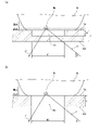
- FIG. 2 (a) and 2 (b) are enlarged cross-sectional views showing an aspect of part A in FIG.
- FIG. 3 is an enlarged view showing a portion where the measurement target portion Mp of the living body Ob is in contact with the target mounting portion 10.
- a recessed portion 10b may be formed on the surface 10a of the target mounting portion 10 so as to form a gap between the target mounting portion 10 and the living body Ob.
- the laser light L1 emitted from the light irradiation unit 20 passes through the bottom surface portion of the recessed portion 10b in the target mounting portion 10 and is irradiated to the surface of the living body Ob. Since the target mounting portion 10 is not opened, it is possible to prevent dust, dirt, water vapor, etc. from entering the atmosphere where the optical system such as the light irradiation portion 20 exists, and the target mounting portion 10 is provided with a dustproof function. be able to.
- the recessed portion 10b By providing the recessed portion 10b, an air layer is formed between the surface 10a of the target mounting portion 10 and the living body Ob, and the surface of the living body Ob is compared with the case where the air layer is brought into contact with the target mounting portion 10. Total internal reflection can be suppressed. Further, by providing the recessed portion 10b, the living body Ob can be more easily adhered to the surface 10a of the target mounting portion 10 in the portion other than the recessed portion 10b except for the portion other than the recessed portion 10b.
- the thickness of the target mounting portion 10 may be 500 ⁇ m
- the width of the recessed portion 10b may be 700 ⁇ m
- the thickness of the air layer in the recessed portion 10b may be about 400 ⁇ m.
- an opening 10c may be formed on the surface 10a of the target mounting portion 10 in a region in contact with the surface of the living body Ob.
- the laser beam L1 emitted from the light irradiation unit 20 by the opening 10c irradiates the surface of the living body Ob through the opening 10c which is a through hole formed in the target mounting portion 10.
- an air layer can be formed at the portion where the surface 10a of the target mounting portion 10 is in contact with the living body Ob, and the living body Ob is compared with the case where the target mounting portion 10 is brought into contact with the air layer. Total internal reflection on the surface can be suppressed. Further, by providing the opening 10c, the living body Ob can be easily adhered to the surface 10a of the target mounting portion 10 around the opening 10c of the surface 10a.
- the thickness of the target mounting portion 10 may be 500 ⁇ m
- the width of the opening 10b may be 700 ⁇ m.
- the light irradiation unit 20 is a light source that irradiates a living body with a laser beam having a specific wavelength toward the measurement target portion Mp.
- the light irradiation unit 20 is arranged on the back surface 10d side of the biological mounting surface 10a of the target mounting unit 10, and the target mounting unit is arranged from the back surface 10d side of the target mounting unit 10.
- a laser beam is irradiated toward the measurement target portion Mp of the living body Ob on the living body mounting surface (surface 10a) of 10.
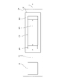
- FIG. 3 is a schematic diagram showing the configuration of the light irradiation unit 20 in the blood substance concentration measuring device 1.
- the light irradiation unit 20 has a light source 21 that oscillates a pump light L0 having a wavelength shorter than that of pulsed mid-infrared light, and converts the light into a long wavelength and amplifies the light L1 to emit the laser light L1.
- It has an optical parametric oscillator 22 (OPO: Optical Parametric Oscillator).
- OPO Optical Parametric Oscillator
- the light irradiation unit 20 outputs the idler light as laser light L1 in the subsequent stage and uses it for measuring the blood glucose level.
- the optical parametric oscillator 22 the configuration described in a known document, for example, Japanese Patent Application Laid-Open No. 2010-281891 may be used.
- the wavelength oscillated by the optical parametric oscillation mid-infrared light is used as the wavelength that is absorbed by glucose more than the conventionally used near-infrared light, and is set to 9.26 ⁇ m in this embodiment.
- this mid-infrared light has a lower transmittance into the body than the near-infrared light conventionally used for measuring blood glucose level, only the epidermis part is observed, and other deep infrared light is observed.
- the effect of being less susceptible to the effects of biological components can be obtained.
- the effect that the overtones of the reference vibration and the overlapping of the combined sounds have little adverse effect on the measurement can be obtained.
- the light source 21 may be provided with a Q-switch Nd: YAG laser (oscillation wavelength 1.064 ⁇ m) or a Q-switch Yb: YAG laser (oscillation wavelength 1.030 ⁇ m).
- the pump light L0 having a shorter wavelength than the mid-infrared light can be oscillated in a pulse shape.
- the pump light L0 may have a pulse width of about 8 ns and a frequency of 10 Hz or more, for example.
- the light source 21 since the light source 21 operates as a passive Q-switch that passively performs a switching operation using a hypersaturated absorber, the light source 21 can be simplified and miniaturized.
- the optical parametric oscillator 22 includes an incident side semitransparent mirror 221, an emitting side semitransparent mirror 222, and a nonlinear optical crystal 223, and is an optical resonator in which the incident side semitransparent mirror 221 and the emitting side semitransparent mirror 222 are opposed to each other.
- a nonlinear optical crystal 223 is arranged therein.
- the light L01 transmitted through the incident side semitransparent mirror 221 is incident on the nonlinear optical crystal 223 and converted into light having a wavelength of 9.26 ⁇ m determined by the nonlinear optical crystal 223, and the incident side semitransparent mirror 221 and the outgoing side semitransparent mirror 222 are converted into light.
- Optical parametric amplification is performed between and.
- the amplified light passes through the emitting side semitransparent mirror 222 and is output as laser light L1.
- the nonlinear optical crystal 223 AgGaS suitable for wavelength conversion is used under the condition of phase matching.
- the wavelength of the oscillated laser beam L1 can be adjusted by adjusting the type and matching conditions of the nonlinear optical crystal 223.
- the nonlinear optical crystal GaSe, ZnGeP 2 , CdSiP 2 , LiInS 2 , LiGaSe 2 , LiInSe 2 , LiGaTe 2 and the like may be used.
- the laser beam L1 emitted from the optical parametric oscillator 22 has a repetition frequency corresponding to the pump light L0, for example, a pulse width of about 8 ns, and a peak output of 10 W to 1 kW can be realized by a short pulse width.
- the light irradiation unit 20 by using the light source 21 and the optical parametric oscillator 22, compared with a conventional light source having a wavelength of 9.26 ⁇ m such as a quantum cascade laser, 10 3 to 10 5 It is possible to obtain a laser beam L1 having about twice as high intensity.
- the optical path Op1 of the laser beam L1 from the light irradiation unit 20 to the measurement target portion Mp is a condensing lens 50 for condensing the irradiation light on the measurement target portion Mp of the living body Ob (the present specification). In the book, it may be referred to as "second lens").
- the laser beam L1 propagates in a space such as in a gas except for a section passing through the condenser lens 50. It is configured.
- the laser light L1 emitted from the light irradiation unit 20 corresponds to the measurement target portion Mp of the living body Ob, for example, the dermis, etc.
- the optical design is such that the light is focused to a depth corresponding to the living body located inward from the dermis.
- the incident angle ⁇ of the laser beam L1 on the measurement target portion Mp is determined by the angle of the light irradiation unit 20 with respect to the surface 10a of the target mounting portion 10 and the refraction angle of the laser light L1 incident on the target mounting portion 10.
- the incident angle ⁇ may be, for example, 45 degrees or more, and further may be 60 degrees or more and 70 degrees or less.
- a beam splitter (not shown) composed of a semitransparent mirror is arranged between the light irradiation unit 20 and the condenser lens 50, and a part of the laser beam L1 is branched as a reference signal to detect light for monitoring.
- a device (not shown) may be used to detect a change in the intensity of the laser beam L1 and used for normalization processing of the detection signal in the light detector 30. The output of the photodetector 30 can be compensated based on the fluctuation of the intensity of the laser beam L1.
- the laser light L1 transmitted through the condenser lens 50 passes through the target mounting portion 10 and is incident on the living body Ob, and is scattered or diffusely reflected by passing through the epithelial interstitial tissue of the living body and is mounted on the target again as the reflected light L2. It passes through the placement portion 10 and is radiated toward the light detector 30.
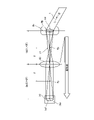
- FIG. 4 is a diagram for explaining an outline of the light path on the light receiving side in the blood substance concentration measuring device 1, and is drawn in a state where the measurement target portion Mp of the living body Ob and the screen 30a of the photodetector 30 are viewed in a plan view. It is a schematic diagram. As shown in FIGS. 1 and 4, in the optical path Op2 of the reflected light L2 from the measurement target portion Mp of the living body Ob to the light detector 30, the reflected light L2 diffusely reflected by the measurement target portion Mp of the living body Ob is emitted.
- An imaging lens 40 (sometimes referred to as a "first lens” in the present specification) for forming an image is arranged on the detector 30.
- the reflected light L2 propagates in a space such as in a gas except for a section passing through the condenser lens 50. It is configured.
- the imaging lens 40 is optical so that the image Im1 in the range corresponding to the measurement target portion Mp of the living body Ob is diffusely reflected and is imaged Im2 on the screen 30a of the photodetector 30 by the imaging lens 40 as reflected light L2. It is designed.
- the distance Op21 between the center of the imaging lens 40 and the measurement target portion Mp of the living body Ob and the distance Op22 between the screen 30a of the photodetector 30 and the center of the imaging lens 40 are set to be equivalent lengths.
- the depth corresponding to the measurement target part Mp of the living body Ob irradiated with infrared light for example, the part of the living body located inward from the dermis such as the dermis (hereinafter, may be referred to as "internal part of the living body").
- the positional relationship is such that the image Im1 is transferred as an image Im2 of an equivalent size on the screen 30a of the photodetector 30.
- the focal length is F with respect to the focal length Fp of the imaging lens 40
- the distance Op21 and the distance Op22 may both be 2F.
- the lengths of the distance Op21 and the distance Op22 are not limited to the above, and the image Im1 of the target mounting portion 10 irradiated with the mid-infrared light is not excessive or deficient in the screen 30a of the photodetector 30.
- the magnification of the distance Op21 and the distance Op22 may be set so as to fit, and the imaging lens 40 that achieves the magnification may be set.
- the angle of incidence of the reflected light L2 on the imaging lens 40 is determined by the angle of the imaging lens 40 with respect to the surface 10a of the target mounting portion 10 and the refraction angle of the reflected light L2 emitted from the target mounting portion 10. In the present embodiment, for example, it may be 0 degrees or more and 40 degrees or less, more preferably 20 degrees or more and 30 degrees or less.
- the photodetector 30 is a mid-infrared sensor that receives the reflected light from the measurement target portion Mp of the irradiated laser light L1 and detects the intensity of the reflected light.
- the photodetector 30 is arranged on the back surface 10d side of the living body mounting surface 10a of the target mounting portion 10, and the living body mounting surface is arranged from the back surface 10d side of the target mounting portion 10.
- (Surface 10a) is configured to receive the reflected light from the measurement target portion Mp in the living body Ob.
- the photodetector 30 outputs an electric signal according to the intensity of the received reflected light.
- an infrared sensor composed of a single element, which outputs the intensity of the reflected light by a one-dimensional voltage value, may be used.
- the intensity of the irradiated laser light L1 is increased by the light irradiation unit 20, and the reflected light reflected from the measurement target portion Mp by the imaging lens 40 is combined on the photodetector 30.
- the photodetector 30 can receive the reflected light having a sufficiently high intensity with respect to the background light, realizes a high S / N ratio, and enables highly accurate measurement.
- the processing required for the light detector 30 is only the detection of the light intensity, and the wavelength is similar to that of the photoacoustic optical method using the quantum cascade laser. There is no need to perform spectral analysis or multivariate analysis based on sweeps. Therefore, the accuracy required for detection is relaxed, and an electronic cooling method or the like that can be easily used can be used.
- an HgCdTe infrared detector cooled with liquid nitrogen may be used. At this time, by cooling to about 77K with liquid nitrogen, the light intensity of the reflected light L2 can be detected with a higher S / N ratio.
- Control unit 60 The control unit 60 is electrically connected to the light irradiation unit 20 and the photodetector 30, drives the light source 21 of the light irradiation unit 20 to oscillate the pulsed pump light L0, and outputs the light from the photodetector 30.
- the light intensity of the reflected light L2 is detected based on the signal, and the glucose concentration in the measurement target portion Mp of the living body Ob is calculated.
- control unit 60 inputs the output of the photodetector for monitoring, and as described above, even if the intensity of the laser light L1 emitted from the light irradiation unit 20 fluctuates, the output of the photodetector for monitoring is output.
- the glucose concentration may be calculated by compensating for the influence of the intensity fluctuation of the laser light L1.
- Test 1 Evaluation of Examples and Comparative Examples of the Blood Substance Concentration Measuring Device 1 [Test equipment, conditions] As an example, the blood substance concentration measuring device 1 according to the embodiment shown in FIG. 1 was used.
- the device conditions of the blood substance concentration measuring device 1 are as follows.
- the image of the measurement target portion Mp of the living body Ob irradiated with the mid-infrared light was transferred by the imaging lens 40 arranged at the lower part of the target mounting portion 10 and imaged on the photodetector 30. ..
- the focal length of the imaging lens 40 is F
- the distance between the screen 30a of the light detector 30 and the center of the imaging lens 40 and the distance between the center of the imaging lens 40 and the measurement target portion Mp of the living body Ob are both. It was set to 2F, and the positional relationship was such that the image Im1 at a depth corresponding to the part of the living body located inward from the epidermis, which corresponds to the measurement target portion Mp, was transferred to the optical detector 30 with a size equivalent to that.
- the angle of the optical path Op2 of the photodetector 30 and the imaging lens 40 was set to an angle inclined by 25 degrees clockwise from the vertical direction of the target mounting portion 10.
- Test method (1) The subject ingested an aqueous solution containing 40 g of glucose (the ingestion time is 0 minutes as the measurement start time), and the subject's fingertip was placed on the upper surface 10a of the target mounting portion 10, and the examples and comparative examples were placed.
- the optical measurement was continuously performed by.
- the blood glucose level was calculated from the change in the intensity of the mid-infrared light when the human body was irradiated with the mid-infrared laser light for a certain period of time.
- SMBG Blood glucose level measurement
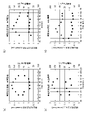
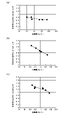
- 5 (a) to 5 (d) show changes in the glucose concentration measured by the photodetector of the conventional device 1X and changes in the glucose concentration measured by the invasive measuring device according to the comparative example. It is the figure which compared with the series. 6 (a) to 6 (d) show the correlation between the measurement result of the glucose concentration by the photodetector and the measurement result of the glucose concentration by the invasive measuring device in FIGS. 5 (a) to 5 (d). It is a figure.
- FIGS. 5 (a) to 5 (d) are the results of tests conducted on the same subject on different test days.
- the blood glucose level due to SMBG rises and then falls with the passage of time after ingesting the aqueous solution.
- the light intensity detected by light measurement is the result of measurement of blood glucose level by SMBG, in which light absorption accompanying an increase in blood glucose concentration causes the ingestion of an aqueous solution, followed by a decrease and an increase with the passage of time. And negative correlation was confirmed (Fig. 6 (a)).
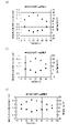
- FIGS. 7 (a) to 7 (c) show changes in the glucose concentration measured by the optical detector of the blood substance concentration measuring device 1 and changes in the glucose concentration measured by the invasive measuring device in chronological order. It is a comparison figure. 8 (a) to 8 (c) show the measurement results of the glucose concentration by the photodetector and the measurement results of the glucose concentration by the invasive blood glucose concentration measuring device in FIGS. 7 (a) to 7 (c). It is a figure which shows the correlation.
- FIGS. 7 (a) to 7 (c) are the results of tests conducted on the same subject on different test days.
- FIGS. 7 (a) to 7 (c) the detected light intensity by measurement is increased after ingesting an aqueous solution due to light absorption accompanying an increase in blood glucose concentration, and then decreases with the passage of time, and the blood glucose level by SMBG increases.
- a high negative correlation was confirmed in FIG. 8 (b)
- a negative correlation was also confirmed in FIGS. 8 (a) and 8 (c).
- FIG. 9 is a schematic diagram of an experimental device for measuring a glucose concentration measurement value by a photodetector by changing the angle of the optical path on the light receiving side and the optical path length in the blood substance concentration measuring device 1.
- the angle ⁇ (hereinafter, may be referred to as “angle ⁇ ”) of the optical path Op2 of the optical detector 30 and the imaging lens 40 is set as the target mounting unit.
- Optical measurement was performed under the condition that the normal degree to the surface on which the living body Ob in No. 10 was placed was different from 0 degrees to 40 degrees clockwise (vertically in FIG. 9).
- Other equipment conditions and test methods are the same as in Test 1.
- [Test results] 10 (a) and 10 (b) are diagrams showing changes in the measured value of glucose concentration when the light receiving angle of the photodetector is changed in the blood substance concentration measuring device 1, and FIG. 10 (a) is a diagram showing an angle ⁇ . The relationship between the and the input / output ratio of the detected light in the optical measurement, (b) is an experimental result showing the variation of the measurement result for each measurement frequency at each angle ⁇ .
- the variation was small at an angle ⁇ of 0 degrees, the variation was the smallest at 25 degrees, and the variation was the largest at 45 degrees.
- the angle ⁇ is 45 degrees or more, it is considered that the angle approaches the specular reflection angle of the incident light.
- the angle ⁇ is 45 degrees or more, it is difficult to measure due to the equipment configuration. In the range where the angle ⁇ is less than 20 degrees, the light receiving side optical system and the emitting side optical system are close to each other, so that it is considered difficult to lay out the optical system of the blood substance concentration measuring device 1.
- the angle ⁇ of the optical path on the light receiving side is preferably 0 degrees or more and 40 degrees or less, and even more preferably 20 degrees or more and 30 degrees or less. Further, in order to suppress the influence of the specular reflection of the incident light, it is preferable that the incident angle of the laser beam is different from the emission angle to the photodetector.
- Distance L (hereinafter, may be referred to as “optical path length L”) is 2F-0.5 [mm], 2F [mm], 2F + 0.5 [mm] with respect to the focal length F of the imaging lens 40.
- Optical measurement was performed under different conditions. Other equipment conditions and test methods are the same as in Test 1.
- [Test results] 11 (a) and 11 (b) show the change in the glucose concentration measured by the light detector when the length of the light path on the light receiving side is changed in the blood substance concentration measuring device 1, and the glucose concentration by the invasive measuring device. It is a figure which compared the change of the measured value of with the time series.
- the detected light intensity by measurement is as described above, in FIG. 7A, the time after ingesting the aqueous solution by light absorption accompanying the increase in blood glucose concentration. It decreased with the passage of time and then increased, and when compared with the measurement result of the blood glucose level by SMBG, a high negative correlation was confirmed in FIG. 8 (a).
- the detected light intensity by measurement is blood as shown in FIGS. 11 (a) and 11 (b). Due to the light absorption accompanying the increase in the medium glucose concentration, there was no tendency for the aqueous solution to be ingested, then decreased with the passage of time, and then increased. In 11 (b), almost no reaction due to the change in blood glucose level was observed. In addition, the result was that the correlation with the measurement result of the blood glucose level by SMBG was low (FIGS. 12 (a) and 12 (b)).
- the optical path length L on the light receiving side that is, the distance L between the screen 30a of the photodetector 30 and the center of the imaging lens 40 and the distance between the center of the imaging lens 40 and the measurement target portion Mp of the living body Ob. It is considered preferable that L has a length corresponding to the imaging position (twice the focal length F) of the imaging lens 40. It is considered that the reflected light from the measurement target portion Mp of the living body Ob corresponding to the living body portion located inward from the epidermis is imaged on the screen 30a of the photodetector 30. At this time, the distance between the upper surface 10a of the object mounting portion 10 corresponding to the skin surface and the center of the imaging lens 40 was about 50 mm, which was about 0.8 mm shorter than the distance L.
- the correlation with the measurement result of the blood glucose level by SMBG is higher than that of the conventional device 1X according to the comparative example, and the reproducibility is high. It was confirmed that high measurement results were obtained.
- an imaging lens 40 is provided between the measurement target portion Mp and the light detector 30, and the reflected light L2 reflected from the measurement target portion Mp is imaged on the light detector 30. It is considered that the adoption of the optical system with the above configuration made it possible to measure light with high reproducibility.
- the conventional device 1X using the waveguide according to the comparative example cannot separate the component from the skin surface and the component absorbed by blood glucose under the skin, and the condition of the skin surface and the slight amount of laser are used.
- normal measurement could not be performed due to changes in irradiation conditions, etc.
- signals from under the skin are collected on the optical sensor, so that the measurement conditions are met. It is probable that the influence of slight changes on the measurement results has decreased, and stable and correct measurement results can be obtained.
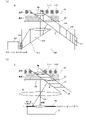
- FIG. 13A is a schematic diagram showing an outline of the optical path from the light irradiation unit 20X to the photodetector 30X in the conventional blood substance concentration measuring device 1X.
- the laser light LX1 irradiated from the light irradiation unit 20 is parallel to the incident side waveguide 91X, and the measurement target portion Mp of the living body Ob.
- the reflected light component (Im11) in the inward portion of the living body below the skin surface that should be the measurement target that can be absorbed by blood glucose the reflected light component (Im12) from the skin surface is generated.
- these reflected light components (Im11, Im12) are configured to enter light into the emitting side waveguide 92X and be guided to the screen 30Xa of the photodetector 30. ..
- the reflected light component (Im12) from the skin surface and the reflected light component (Im11) in the inward portion of the living body below the skin surface are not separated, and both components are mixed by the photodetector. Detected.
- the measurement result includes a reflected light component (Im12) other than the reflected light component (Im11) in the inner part of the living body below the skin surface to be measured, fluctuation factors increase and the reproducibility is low. It is thought that it became.
- FIG. 13B is a schematic diagram showing an outline of the optical path from the light irradiation unit 20 to the photodetector 30 in the blood substance concentration measuring device 1.
- the laser light L1 irradiated from the light irradiation unit 20 is similarly the living body Ob along the optical path toward the inspection target portion Mp of the living body Ob.
- the reflected light component (Im11) in the inward part of the living body below the skin surface that should be absorbed by blood glucose and become the measurement target part Mp the reflected light component (Im12) from the skin surface Occur.
- the image pickup lens 40 allows the reflected light component (Im11) mainly in the inner part of the living body among these reflected light components (Im11, Im12) to be the photodetector 30. It is configured to be imaged on the screen 30a.
- the reflected light component (Im12) from the skin surface enters the imaging lens 40, but since the angle of incidence on the imaging lens 40 is different from the reflected light component (Im11) in the inner part of the living body, light detection is performed.
- the reflected light component (Im11) in the inward portion of the living body below the skin surface, which should be mainly measured, is imaged on the screen 30a of the photodetector 30 and is a photodetector. Since it is reflected in the optical measurement by 30, it is considered that the measurement result has a high correlation with the measurement result of the blood glucose level by SMBG and has high reproducibility as compared with the comparative example.
- the blood substance concentration measuring device 1 can reduce the false signal (noise) component due to the reflected light scattered on the skin surface as compared with the conventional device 1X using the waveguide, and can measure the light. S / N ratio can be improved. Further, for this reason, it is possible to always perform highly accurate optical measurement regardless of the state of the skin surface that fluctuates depending on the subject and the measurement. Further, it is possible to obtain an effect that the optical path length L on the light receiving side can be changed by adjusting the position of the photodetector to cope with a measurement target having a thick skin.
- the blood substance concentration measuring device 1 is a blood substance concentration measuring device 1 for measuring the concentration of a substance contained in the blood of the living body Ob, and is the living body Ob.
- the light irradiation unit 20 that irradiates the measurement target portion Mp with the laser beam L1 from the target mounting portion 10 on which the measurement target portion Mp is placed and the back surface 10d side of the biological mounting surface (front surface 10a) of the target mounting portion 10.
- the light detector 30 that receives the reflected light L2 from the measurement target portion Mp of the laser light L1 irradiated on the back surface 10d side of the target mounting portion 10 and detects the intensity of the reflected light L2, and the measurement target portion.
- An imaging lens 40 is provided between the Mp and the light detector 30, and the laser beam L2 is provided in the section from the target mounting portion 10 to the light detector 40 in the optical path Op2 from the measurement target portion Mp to the light detector 30. Propagates in space except for a section passing through the imaging lens 40, and the imaging lens 40 is characterized in that the reflected light L2 reflected from the measurement target portion Mp is imaged on the light detector 30. ..
- the blood substance concentration measuring device 1 includes a target mounting unit 10, a light irradiation unit 20, a photodetector 30, and an imaging lens 40, and the imaging lens 40 is a measurement target portion.
- the reflected light L2 reflected from the Mp is formed into an image on the photodetector 30.
- the specific configuration for the imaging lens 40 to form an image of the reflected light L2 reflected from the measurement target portion Mp on the photodetector 30 is not limited to these, and may be another embodiment. good.
- FIG. 14 is a schematic diagram showing the configuration of the blood substance concentration measuring device 1A according to the second embodiment.
- the same configuration as that of the blood substance concentration measuring device 1 is assigned the same number, and the description thereof will be omitted.
- the relative positional relationship with respect to the measurement target portion Mp is equivalent to that of the light detector 30.
- a two-dimensional imaging means that receives the reflected light (Im11) reflected from the measurement target portion Mp and detects whether or not an image based on the reflected light (Im11) is formed. It differs from the first embodiment in that it is provided with 71A.
- the two-dimensional image pickup means 71A is a two-dimensional infrared image pickup element array in which a plurality of light receiving elements capable of detecting mid-infrared light are arranged in a matrix on the light receiving surface 71Aa. As shown in FIG. 14, the two-dimensional imaging means 71A is integrated with the photodetector 30 to form a photodetector unit 70A, and the optical path of the photodetector unit 70A from the measurement target portion Mp to the imaging lens 40. It is configured to be slidable in the direction perpendicular to L2.
- the relative positional relationship of the light receiving surface 71Aa of the two-dimensional image pickup means 71A with respect to the measurement target portion Mp is the screen of the photodetector 30 with respect to the measurement target portion Mp. They are arranged so as to be equivalent to the relative positional relationship of 30a.
- the photodetector 30 performs a step of adjusting the optical path length from the measurement target portion Mp to the photodetector 30 in order to form an image of the reflected light (Im11) from the measurement target portion Mp on the photodetector 30.
- FIG. 15 is a schematic diagram for explaining an operation of adjusting the optical path length from the measurement target portion Mp to the photodetector 30 by the blood substance concentration measuring device 1A.
- the relative positional relationship of the light receiving surface 71Aa of the two-dimensional imaging means 71A with respect to the measurement target portion Mp on the optical path L2 is the light detection with respect to the measurement target portion Mp. It is arranged at a position equivalent to the relative positional relationship of the screen 30a of the vessel 30.
- the two-dimensional image pickup means 71A receives the reflected light reflected from the measurement target portion Mp, detects whether or not an image based on the reflected light is formed, and forms an image. If not, the position of the two-dimensional image pickup means 71A on the optical path L2 is gradually moved, and the detection of whether or not an image is formed is repeated.
- the focus position of the image in the memory changes by scanning the two-dimensional imaging means 71A along the optical path L2. This is determined by image analysis, and the position of the two-dimensional image pickup means 71A when the irradiation position and the focus position examined in advance match is determined as the image formation position.
- a scale with a scale of 0.5 mm increments is mounted on the target mounting portion 10, and an image is acquired by the two-dimensional imaging means 71A. This is done by detecting the focus position in the image.
- the focus position may be the maximum point of the luminance distribution in the image.
- the photodetection unit 70A is gradually moved in parallel with the optical path L2 until the focus position in the acquired image and the irradiation position of the laser beam L1 coincide with each other on the optical path L2, and the presence or absence of an image formation is determined.
- the two-dimensional image pickup means 71A is returned to the photodetector 30, and the optical path length from the measurement target portion Mp to the photodetector 30 is determined.
- the measurement target portion is configured so that the relative positional relationship with respect to the measurement target portion Mp can be arranged so as to be equivalent to the photodetector 30.
- the configuration is provided with a two-dimensional image pickup means 71A that receives the reflected light (Im11) reflected from the Mp and detects whether or not an image based on the reflected light (Im11) is formed.
- the photodetector 30 performs the step of adjusting the optical path length from the measurement target portion Mp to the photodetector 30 in order to form an image of the reflected light (Im11) from the measurement target portion Mp on the photodetector 30. It can be replaced with the two-dimensional imaging means 71A. As a result, it is possible to easily construct the blood substance concentration measuring device 1A capable of stably performing highly accurate measurement regardless of the state of the measurement target and the fluctuation of the irradiation condition of the laser beam.
- Embodiment 3 In the blood substance concentration measuring devices 1 and 2 according to the first embodiment, the wavelength of the laser beam L1 emitted by the light irradiation unit 20 is 9.26 ⁇ m, and the blood component to be detected is glucose.
- the wavelength of the laser beam L1 emitted by the light irradiation unit 20 may be different depending on the type of blood component to be detected.
- the wavelength of the laser beam L1 emitted by the light irradiation unit 20 may be 8.23 ⁇ 0.05 ⁇ m (8.18 ⁇ m or more and 8.28 ⁇ m or less), and the blood component may be set. Is characterized by being lactic acid.
- the wavelength may range from 5.77 ⁇ m, 6.87 ⁇ m, 7.27 ⁇ m, 8.87 ⁇ m, or 9.55 ⁇ m to ⁇ 0.05 ⁇ m or more and +0.05 ⁇ m or less.
- FIG. 16 is a diagram showing changes in the measured value of lactic acid concentration by a photodetector when the wavelength of the light emitted by the light irradiation unit 20 is 8.23 ⁇ m in the blood substance concentration measuring device according to the third embodiment. be. As shown in FIG. 16, it was confirmed that the measured value by optical measurement generally correlates with the measurement result (comparative value) of the lactate value by self-collecting blood.
- the apparatus can be realized by changing the optical parametric oscillator 22 having different phase matching conditions of the nonlinear crystal 223.
- a plurality of types of blood components can be selectively used by selectively using a plurality of optical parametric oscillators 22 and adopting a device configuration capable of selectively irradiating laser light L1 having a plurality of wavelengths. May be a device capable of measuring.
- the blood substance concentration measuring device is different from the configuration that employs an optical system using a waveguide in which the width and thickness of the optical path differ depending on the wavelength of the light to be guided, for example, glucose.
- An optical system including a condenser lens 50, an object mounting portion 10, an imaging lens 40, and a light detector 30 capable of detecting mid-infrared light can be shared with a measuring device for other blood components such as. ..
- the blood substance concentration measuring device it is possible to detect different types of blood components by changing the wavelength of the laser beam L1 emitted by the light irradiation unit 20.
- a plurality of types of different blood components can be detected by selectively irradiating laser light L1 having different wavelengths with the same measuring device.
- the embodiment of the blood substance concentration measuring device is shown by taking as an example an optical system provided with an imaging lens 40 between the measurement target portion Mp and the photodetector 30.
- the blood substance concentration measuring device according to the present disclosure may be configured to form an image of the reflected light L2 reflected from the measurement target portion Mp of the living body Ob on the photodetector 30, and may be optical on the light receiving side.
- the system may be appropriately modified to another embodiment. For example, a configuration using a plurality of lenses or a configuration in which a mirror is arranged in the middle of the optical path may be used.
- the embodiment is shown by taking glucose or lactic acid as an example of the blood component to be detected by the blood substance concentration measuring device.
- the detectable blood component of the blood substance concentration measuring device according to the present disclosure is not limited to the above, and the wavelength of the laser light L1 emitted by the light irradiation unit 20 is set according to the type of the blood component. By making them different, the device can be widely used for other detection targets.
- the photodetector 30 shows the embodiment by taking as an example an infrared sensor composed of a single light receiving element capable of detecting mid-infrared light.
- the photodetector 30 may be a two-dimensional infrared image pickup element array in which a plurality of light receiving elements capable of detecting mid-infrared light are arranged in a matrix on the light receiving surface.
- the step of adjusting the optical path length from the measurement target portion Mp to the photodetector 30 for forming an image of the reflected light from the measurement target portion Mp on the photodetector 30 is performed by using the photodetector 30 itself. It will be possible to do.
- the photodetector 30 receives the reflected light reflected from the measurement target portion Mp, and detects whether or not an image based on the reflected light is formed.
- the position of the photodetector 30 on the optical path L2 is gradually moved, and the detection of whether or not the image is formed is repeated.
- the step of adjusting the optical path length from the measurement target portion Mp to the photodetector 30 can be performed using the photodetector 30 itself, and the apparatus can be simplified as compared with the second embodiment.
- the light irradiation unit 20 emits laser light from the back surface 10d side of the biological mounting surface (front surface 10a) of the target mounting unit 10 to the measurement target portion Mp.
- the photodetector 30 is configured to irradiate L1 and receive the reflected light L2 from the measurement target portion of the laser light L1 irradiated on the back surface 10d side of the target mounting portion 10.
- the light irradiation unit 20 may be configured to irradiate the measurement target portion Mp with the laser beam L1 from the surface 10a side of the biological mounting surface (surface 10a) of the target mounting unit 10.
- the photodetector 30 may be configured to receive the reflected light L2 from the measurement target portion of the laser beam L1 irradiated on the surface 10a side of the target mounting portion 10.
- the measurement target portion Mp of the living body Ob is placed upward on the target placing portion 10, and the living body Ob is slightly compressed from above on the plate material through which the laser light L1 is transmitted (transparent to the laser light).
- the height of the measurement target portion Mp with respect to the target mounting portion 10 (and the light irradiation portion 20) may be defined.
- an optical means for detecting the position of the measurement target portion Mp by irradiating the laser beam and measuring the time until the reflected light from the measurement target portion Mp of the living body Ob is received is provided, and the detected measurement target is detected. It may be configured to provide feedback such as different irradiation directions and focusing distances of the laser beam L1 in the measurement of the blood substance concentration based on the position information of the partial Mp.
- the light irradiation unit 20 irradiates the measurement target portion Mp with the laser beam L1 from the surface 10a side of the living body mounting surface (surface 10a) without passing through the target mounting portion 10 to measure the blood substance concentration. Can be done.
- the order in which the above method is executed is for exemplifying for concretely explaining the present invention, and may be an order other than the above. Moreover, a part of the above-mentioned method may be executed at the same time (parallel) with another method.
- the blood substance concentration measuring device and the blood substance concentration measuring method according to one aspect of the present disclosure routinely measure blood substance states such as blood glucose level and blood lipid level in the prevention and treatment of lifestyle diseases. It can be widely used as a medical device.
Landscapes
- Health & Medical Sciences (AREA)
- Physics & Mathematics (AREA)
- Life Sciences & Earth Sciences (AREA)
- General Health & Medical Sciences (AREA)
- Pathology (AREA)
- Spectroscopy & Molecular Physics (AREA)
- Biophysics (AREA)
- Heart & Thoracic Surgery (AREA)
- Immunology (AREA)
- Biochemistry (AREA)
- Chemical & Material Sciences (AREA)
- Optics & Photonics (AREA)
- Analytical Chemistry (AREA)
- Engineering & Computer Science (AREA)
- Biomedical Technology (AREA)
- General Physics & Mathematics (AREA)
- Medical Informatics (AREA)
- Molecular Biology (AREA)
- Surgery (AREA)
- Animal Behavior & Ethology (AREA)
- Public Health (AREA)
- Veterinary Medicine (AREA)
- Emergency Medicine (AREA)
- Measurement Of The Respiration, Hearing Ability, Form, And Blood Characteristics Of Living Organisms (AREA)
Priority Applications (5)
| Application Number | Priority Date | Filing Date | Title |
|---|---|---|---|
| JP2022554067A JP7620337B2 (ja) | 2020-09-30 | 2021-09-29 | 血中物質濃度測定装置及び血中物質濃度測定方法 |
| EP21875739.1A EP4224147A4 (en) | 2020-09-30 | 2021-09-29 | DEVICE FOR MEASURING THE CONCENTRATION OF A SUBSTANCE IN BLOOD AND METHOD FOR MEASURING THE CONCENTRATION OF A SUBSTANCE IN BLOOD |
| US18/027,165 US20230355142A1 (en) | 2020-09-30 | 2021-09-29 | Substance-in-blood concentration measurement device and substance-in-blood concentration measurement method |
| JP2024233126A JP7762457B2 (ja) | 2020-09-30 | 2024-12-27 | 血中物質濃度測定方法 |
| JP2025172138A JP2026004595A (ja) | 2020-09-30 | 2025-10-10 | 血中物質濃度測定装置及び血中物質濃度測定方法 |
Applications Claiming Priority (2)
| Application Number | Priority Date | Filing Date | Title |
|---|---|---|---|
| JP2020-165688 | 2020-09-30 | ||
| JP2020165688 | 2020-09-30 |
Publications (1)
| Publication Number | Publication Date |
|---|---|
| WO2022071442A1 true WO2022071442A1 (ja) | 2022-04-07 |
Family
ID=80951676
Family Applications (1)
| Application Number | Title | Priority Date | Filing Date |
|---|---|---|---|
| PCT/JP2021/035990 Ceased WO2022071442A1 (ja) | 2020-09-30 | 2021-09-29 | 血中物質濃度測定装置及び血中物質濃度測定方法 |
Country Status (4)
| Country | Link |
|---|---|
| US (1) | US20230355142A1 (https=) |
| EP (1) | EP4224147A4 (https=) |
| JP (3) | JP7620337B2 (https=) |
| WO (1) | WO2022071442A1 (https=) |
Cited By (4)
| Publication number | Priority date | Publication date | Assignee | Title |
|---|---|---|---|---|
| WO2024057553A1 (ja) * | 2022-09-17 | 2024-03-21 | ライトタッチテクノロジー株式会社 | 血中物質濃度測定装置、血中物質濃度測定方法及びプログラム |
| WO2024257283A1 (ja) * | 2023-06-14 | 2024-12-19 | 株式会社フジタ医科器械 | 分量検出装置及び分量検出方法、並びに細胞培養システム |
| EP4353150A4 (en) * | 2022-08-09 | 2025-01-22 | Fujita Medical Instruments Co., Ltd. | DEVICE FOR RECOGNIZING BIOMETRIC INFORMATION AND METHOD FOR RECOGNIZING BIOMETRIC INFORMATION |
| EP4703724A4 (en) * | 2023-04-27 | 2026-03-04 | Fujita Medical Instr Co Ltd | DEVICE FOR DETECTING BIOLOGICAL INFORMATION AND METHOD FOR DETECTING BIOLOGICAL INFORMATION |
Families Citing this family (1)
| Publication number | Priority date | Publication date | Assignee | Title |
|---|---|---|---|---|
| JP2024060420A (ja) * | 2022-10-19 | 2024-05-02 | キヤノン株式会社 | 画像取得装置、画像取得方法、及びプログラム |
Citations (10)
| Publication number | Priority date | Publication date | Assignee | Title |
|---|---|---|---|---|
| JP2001153796A (ja) * | 1999-11-25 | 2001-06-08 | Shimadzu Corp | 光生体測定装置 |
| JP2009168670A (ja) * | 2008-01-17 | 2009-07-30 | Sanyo Electric Co Ltd | 光学測定ユニット |
| JP2010276407A (ja) * | 2009-05-27 | 2010-12-09 | Spectratech Inc | 光検出装置および生体情報測定装置 |
| JP2010281891A (ja) | 2009-06-02 | 2010-12-16 | Japan Atomic Energy Agency | レーザー装置及びレーザー増幅方法 |
| WO2016117520A1 (ja) | 2015-01-21 | 2016-07-28 | 国立研究開発法人日本原子力研究開発機構 | 血中物質濃度測定装置及び血中物質濃度測定方法 |
| JP2017509373A (ja) * | 2011-01-28 | 2017-04-06 | バー‐イラン、ユニバーシティーBar−Ilan University | 個体の生物学的または生化学的パラメータを非侵襲的に監視する方法及びシステム |
| JP2018141761A (ja) * | 2017-02-28 | 2018-09-13 | 日機装株式会社 | 分析装置 |
| JP2018157928A (ja) * | 2017-03-22 | 2018-10-11 | 株式会社モフィリア | 生体情報取得装置、生体情報取得方法、及び、生体情報取得プログラム |
| JP2018534031A (ja) * | 2015-09-30 | 2018-11-22 | チ シン | 生体信号を測定するための装置および方法 |
| JP2019507320A (ja) * | 2015-12-09 | 2019-03-14 | ディアモンテク、ゲゼルシャフト、ミット、ベシュレンクテル、ハフツングDiamontech Gmbh | 物質を分析するための装置及び方法 |
Family Cites Families (5)
| Publication number | Priority date | Publication date | Assignee | Title |
|---|---|---|---|---|
| US5598842A (en) * | 1993-09-03 | 1997-02-04 | Toa Medical Electronics Co., Ltd. | Non-invasive blood analyzer and method using the same |
| US7697966B2 (en) * | 2002-03-08 | 2010-04-13 | Sensys Medical, Inc. | Noninvasive targeting system method and apparatus |
| TWI489325B (zh) * | 2011-09-21 | 2015-06-21 | Pixart Imaging Inc | 光學手指滑鼠、電子裝置及生理特徵偵測裝置 |
| WO2013129519A1 (ja) | 2012-02-29 | 2013-09-06 | 国立大学法人香川大学 | 分光特性測定装置及び分光特性測定方法 |
| US11280728B2 (en) * | 2015-12-09 | 2022-03-22 | Diamontech Ag | Device and method for analyzing a material |
-
2021
- 2021-09-29 EP EP21875739.1A patent/EP4224147A4/en active Pending
- 2021-09-29 JP JP2022554067A patent/JP7620337B2/ja active Active
- 2021-09-29 US US18/027,165 patent/US20230355142A1/en active Pending
- 2021-09-29 WO PCT/JP2021/035990 patent/WO2022071442A1/ja not_active Ceased
-
2024
- 2024-12-27 JP JP2024233126A patent/JP7762457B2/ja active Active
-
2025
- 2025-10-10 JP JP2025172138A patent/JP2026004595A/ja active Pending
Patent Citations (10)
| Publication number | Priority date | Publication date | Assignee | Title |
|---|---|---|---|---|
| JP2001153796A (ja) * | 1999-11-25 | 2001-06-08 | Shimadzu Corp | 光生体測定装置 |
| JP2009168670A (ja) * | 2008-01-17 | 2009-07-30 | Sanyo Electric Co Ltd | 光学測定ユニット |
| JP2010276407A (ja) * | 2009-05-27 | 2010-12-09 | Spectratech Inc | 光検出装置および生体情報測定装置 |
| JP2010281891A (ja) | 2009-06-02 | 2010-12-16 | Japan Atomic Energy Agency | レーザー装置及びレーザー増幅方法 |
| JP2017509373A (ja) * | 2011-01-28 | 2017-04-06 | バー‐イラン、ユニバーシティーBar−Ilan University | 個体の生物学的または生化学的パラメータを非侵襲的に監視する方法及びシステム |
| WO2016117520A1 (ja) | 2015-01-21 | 2016-07-28 | 国立研究開発法人日本原子力研究開発機構 | 血中物質濃度測定装置及び血中物質濃度測定方法 |
| JP2018534031A (ja) * | 2015-09-30 | 2018-11-22 | チ シン | 生体信号を測定するための装置および方法 |
| JP2019507320A (ja) * | 2015-12-09 | 2019-03-14 | ディアモンテク、ゲゼルシャフト、ミット、ベシュレンクテル、ハフツングDiamontech Gmbh | 物質を分析するための装置及び方法 |
| JP2018141761A (ja) * | 2017-02-28 | 2018-09-13 | 日機装株式会社 | 分析装置 |
| JP2018157928A (ja) * | 2017-03-22 | 2018-10-11 | 株式会社モフィリア | 生体情報取得装置、生体情報取得方法、及び、生体情報取得プログラム |
Non-Patent Citations (1)
| Title |
|---|
| See also references of EP4224147A4 |
Cited By (6)
| Publication number | Priority date | Publication date | Assignee | Title |
|---|---|---|---|---|
| EP4353150A4 (en) * | 2022-08-09 | 2025-01-22 | Fujita Medical Instruments Co., Ltd. | DEVICE FOR RECOGNIZING BIOMETRIC INFORMATION AND METHOD FOR RECOGNIZING BIOMETRIC INFORMATION |
| US12474259B2 (en) | 2022-08-09 | 2025-11-18 | Fujita Medical Instruments Co., Ltd. | Biological information detection device and biological information detection method |
| WO2024057553A1 (ja) * | 2022-09-17 | 2024-03-21 | ライトタッチテクノロジー株式会社 | 血中物質濃度測定装置、血中物質濃度測定方法及びプログラム |
| EP4364660A4 (en) * | 2022-09-17 | 2025-02-26 | Light Touch Technology Incorporated | DEVICE FOR MEASURING THE CONCENTRATION OF A BLOOD SUBSTANCE, METHOD FOR MEASURING THE CONCENTRATION OF A BLOOD SUBSTANCE AND PROGRAM |
| EP4703724A4 (en) * | 2023-04-27 | 2026-03-04 | Fujita Medical Instr Co Ltd | DEVICE FOR DETECTING BIOLOGICAL INFORMATION AND METHOD FOR DETECTING BIOLOGICAL INFORMATION |
| WO2024257283A1 (ja) * | 2023-06-14 | 2024-12-19 | 株式会社フジタ医科器械 | 分量検出装置及び分量検出方法、並びに細胞培養システム |
Also Published As
| Publication number | Publication date |
|---|---|
| EP4224147A1 (en) | 2023-08-09 |
| US20230355142A1 (en) | 2023-11-09 |
| EP4224147A4 (en) | 2024-03-13 |
| JPWO2022071442A1 (https=) | 2022-04-07 |
| JP7762457B2 (ja) | 2025-10-30 |
| JP7620337B2 (ja) | 2025-01-23 |
| JP2025032031A (ja) | 2025-03-07 |
| JP2026004595A (ja) | 2026-01-14 |
Similar Documents
| Publication | Publication Date | Title |
|---|---|---|
| US11412963B2 (en) | Method for measuring concentration of substance in blood | |
| JP7762457B2 (ja) | 血中物質濃度測定方法 | |
| US6167290A (en) | Method and apparatus of non-invasive measurement of human/animal blood glucose and other metabolites | |
| US9226666B2 (en) | Confocal photoacoustic microscopy with optical lateral resolution | |
| US7613487B2 (en) | Instrument for noninvasively measuring blood sugar level | |
| EP2207474B1 (en) | Optical sensor for determining the concentration of an analyte | |
| JP2010088873A (ja) | 生体情報イメージング装置 | |
| US12433513B2 (en) | Device for non-invasive blood glucose concentration measurement | |
| JP7541301B2 (ja) | 血中物質濃度測定装置、血中物質濃度測定方法及びプログラム | |
| US20250134421A1 (en) | In-blood substance concentration measurement device, in-blood substance concentration measurement method, and program | |
| US20240415424A1 (en) | In-blood substance concentration measurement device, in-blood substance concentration measurement method, and program | |
| JP2023029143A (ja) | 無侵襲血糖値測定器 | |
| JP7439456B2 (ja) | 生体情報測定装置、及び生体情報測定方法 | |
| HK1243902B (zh) | 血中物质浓度测定装置以及血中物质浓度测定方法 | |
| HK1151958B (en) | Optical sensor for determining the concentration of an analyte | |
| HK1172229B (en) | An optical sensor for determining the concentration of an analyte |
Legal Events
| Date | Code | Title | Description |
|---|---|---|---|
| 121 | Ep: the epo has been informed by wipo that ep was designated in this application |
Ref document number: 21875739 Country of ref document: EP Kind code of ref document: A1 |
|
| ENP | Entry into the national phase |
Ref document number: 2022554067 Country of ref document: JP Kind code of ref document: A |
|
| NENP | Non-entry into the national phase |
Ref country code: DE |
|
| ENP | Entry into the national phase |
Ref document number: 2021875739 Country of ref document: EP Effective date: 20230502 |