WO2022071442A1 - Substance-in-blood concentration measurement device and substance-in-blood concentration measurement method - Google Patents
Substance-in-blood concentration measurement device and substance-in-blood concentration measurement method Download PDFInfo
- Publication number
- WO2022071442A1 WO2022071442A1 PCT/JP2021/035990 JP2021035990W WO2022071442A1 WO 2022071442 A1 WO2022071442 A1 WO 2022071442A1 JP 2021035990 W JP2021035990 W JP 2021035990W WO 2022071442 A1 WO2022071442 A1 WO 2022071442A1
- Authority
- WO
- WIPO (PCT)
- Prior art keywords
- light
- measurement target
- photodetector
- blood
- target portion
- Prior art date
Links
- 238000005259 measurement Methods 0.000 title claims abstract description 273
- 239000008280 blood Substances 0.000 title claims abstract description 182
- 238000000691 measurement method Methods 0.000 title claims description 6
- 210000004369 blood Anatomy 0.000 claims abstract description 179
- 230000003287 optical effect Effects 0.000 claims abstract description 148
- 239000000126 substance Substances 0.000 claims abstract description 129
- 238000003384 imaging method Methods 0.000 claims abstract description 54
- WQZGKKKJIJFFOK-GASJEMHNSA-N Glucose Natural products OC[C@H]1OC(O)[C@H](O)[C@@H](O)[C@@H]1O WQZGKKKJIJFFOK-GASJEMHNSA-N 0.000 claims description 85
- 239000008103 glucose Substances 0.000 claims description 85
- 210000003491 skin Anatomy 0.000 claims description 35
- 238000000034 method Methods 0.000 claims description 31
- 239000012503 blood component Substances 0.000 claims description 17
- JVTAAEKCZFNVCJ-UHFFFAOYSA-N lactic acid Chemical group CC(O)C(O)=O JVTAAEKCZFNVCJ-UHFFFAOYSA-N 0.000 claims description 12
- 238000001514 detection method Methods 0.000 claims description 11
- 210000002615 epidermis Anatomy 0.000 claims description 10
- 230000001678 irradiating effect Effects 0.000 claims description 7
- 235000014655 lactic acid Nutrition 0.000 claims description 6
- 239000004310 lactic acid Substances 0.000 claims description 6
- 230000015572 biosynthetic process Effects 0.000 claims description 5
- 239000000463 material Substances 0.000 claims description 5
- 239000011159 matrix material Substances 0.000 claims description 4
- 125000002791 glucosyl group Chemical group C1([C@H](O)[C@@H](O)[C@H](O)[C@H](O1)CO)* 0.000 claims 1
- 239000000306 component Substances 0.000 description 35
- 238000012360 testing method Methods 0.000 description 27
- 238000010586 diagram Methods 0.000 description 23
- 230000000052 comparative effect Effects 0.000 description 12
- 239000013078 crystal Substances 0.000 description 11
- 239000007864 aqueous solution Substances 0.000 description 8
- 230000000694 effects Effects 0.000 description 7
- 238000010521 absorption reaction Methods 0.000 description 6
- 230000007423 decrease Effects 0.000 description 5
- 210000004207 dermis Anatomy 0.000 description 5
- 238000011156 evaluation Methods 0.000 description 5
- 230000006870 function Effects 0.000 description 5
- 239000010410 layer Substances 0.000 description 5
- 230000031700 light absorption Effects 0.000 description 5
- IJGRMHOSHXDMSA-UHFFFAOYSA-N Atomic nitrogen Chemical compound N#N IJGRMHOSHXDMSA-UHFFFAOYSA-N 0.000 description 4
- 230000003247 decreasing effect Effects 0.000 description 4
- 238000012544 monitoring process Methods 0.000 description 4
- 230000010355 oscillation Effects 0.000 description 4
- 238000002834 transmittance Methods 0.000 description 4
- 238000006243 chemical reaction Methods 0.000 description 3
- 201000010099 disease Diseases 0.000 description 3
- 208000037265 diseases, disorders, signs and symptoms Diseases 0.000 description 3
- 239000000428 dust Substances 0.000 description 3
- 238000010998 test method Methods 0.000 description 3
- JVTAAEKCZFNVCJ-UHFFFAOYSA-M Lactate Chemical compound CC(O)C([O-])=O JVTAAEKCZFNVCJ-UHFFFAOYSA-M 0.000 description 2
- 238000010241 blood sampling Methods 0.000 description 2
- 238000001816 cooling Methods 0.000 description 2
- 206010012601 diabetes mellitus Diseases 0.000 description 2
- 238000002474 experimental method Methods 0.000 description 2
- 210000003722 extracellular fluid Anatomy 0.000 description 2
- 230000037406 food intake Effects 0.000 description 2
- 239000007789 gas Substances 0.000 description 2
- 150000002632 lipids Chemical class 0.000 description 2
- 239000007788 liquid Substances 0.000 description 2
- 238000012986 modification Methods 0.000 description 2
- 230000004048 modification Effects 0.000 description 2
- 229910052757 nitrogen Inorganic materials 0.000 description 2
- 230000002265 prevention Effects 0.000 description 2
- 238000012545 processing Methods 0.000 description 2
- XLYOFNOQVPJJNP-UHFFFAOYSA-N water Chemical compound O XLYOFNOQVPJJNP-UHFFFAOYSA-N 0.000 description 2
- 229910005543 GaSe Inorganic materials 0.000 description 1
- 102000003960 Ligases Human genes 0.000 description 1
- 108090000364 Ligases Proteins 0.000 description 1
- 229910000661 Mercury cadmium telluride Inorganic materials 0.000 description 1
- 239000006096 absorbing agent Substances 0.000 description 1
- 230000002411 adverse Effects 0.000 description 1
- 230000003321 amplification Effects 0.000 description 1
- 238000004458 analytical method Methods 0.000 description 1
- 238000013459 approach Methods 0.000 description 1
- WQZGKKKJIJFFOK-VFUOTHLCSA-N beta-D-glucose Chemical compound OC[C@H]1O[C@@H](O)[C@H](O)[C@@H](O)[C@@H]1O WQZGKKKJIJFFOK-VFUOTHLCSA-N 0.000 description 1
- 210000004204 blood vessel Anatomy 0.000 description 1
- 239000011247 coating layer Substances 0.000 description 1
- 230000002950 deficient Effects 0.000 description 1
- 238000013461 design Methods 0.000 description 1
- 238000010191 image analysis Methods 0.000 description 1
- 238000007689 inspection Methods 0.000 description 1
- 239000000203 mixture Substances 0.000 description 1
- 238000000491 multivariate analysis Methods 0.000 description 1
- 238000010606 normalization Methods 0.000 description 1
- 238000003199 nucleic acid amplification method Methods 0.000 description 1
- 230000001105 regulatory effect Effects 0.000 description 1
- SBIBMFFZSBJNJF-UHFFFAOYSA-N selenium;zinc Chemical compound [Se]=[Zn] SBIBMFFZSBJNJF-UHFFFAOYSA-N 0.000 description 1
- 238000010183 spectrum analysis Methods 0.000 description 1
- 239000013589 supplement Substances 0.000 description 1
- 210000001519 tissue Anatomy 0.000 description 1
Images


Classifications
-
- G—PHYSICS
- G01—MEASURING; TESTING
- G01N—INVESTIGATING OR ANALYSING MATERIALS BY DETERMINING THEIR CHEMICAL OR PHYSICAL PROPERTIES
- G01N21/00—Investigating or analysing materials by the use of optical means, i.e. using sub-millimetre waves, infrared, visible or ultraviolet light
- G01N21/17—Systems in which incident light is modified in accordance with the properties of the material investigated
- G01N21/25—Colour; Spectral properties, i.e. comparison of effect of material on the light at two or more different wavelengths or wavelength bands
- G01N21/31—Investigating relative effect of material at wavelengths characteristic of specific elements or molecules, e.g. atomic absorption spectrometry
- G01N21/35—Investigating relative effect of material at wavelengths characteristic of specific elements or molecules, e.g. atomic absorption spectrometry using infrared light
- G01N21/3577—Investigating relative effect of material at wavelengths characteristic of specific elements or molecules, e.g. atomic absorption spectrometry using infrared light for analysing liquids, e.g. polluted water
-
- A—HUMAN NECESSITIES
- A61—MEDICAL OR VETERINARY SCIENCE; HYGIENE
- A61B—DIAGNOSIS; SURGERY; IDENTIFICATION
- A61B5/00—Measuring for diagnostic purposes; Identification of persons
- A61B5/145—Measuring characteristics of blood in vivo, e.g. gas concentration, pH value; Measuring characteristics of body fluids or tissues, e.g. interstitial fluid, cerebral tissue
- A61B5/14532—Measuring characteristics of blood in vivo, e.g. gas concentration, pH value; Measuring characteristics of body fluids or tissues, e.g. interstitial fluid, cerebral tissue for measuring glucose, e.g. by tissue impedance measurement
-
- A—HUMAN NECESSITIES
- A61—MEDICAL OR VETERINARY SCIENCE; HYGIENE
- A61B—DIAGNOSIS; SURGERY; IDENTIFICATION
- A61B5/00—Measuring for diagnostic purposes; Identification of persons
- A61B5/145—Measuring characteristics of blood in vivo, e.g. gas concentration, pH value; Measuring characteristics of body fluids or tissues, e.g. interstitial fluid, cerebral tissue
- A61B5/1455—Measuring characteristics of blood in vivo, e.g. gas concentration, pH value; Measuring characteristics of body fluids or tissues, e.g. interstitial fluid, cerebral tissue using optical sensors, e.g. spectral photometrical oximeters
-
- G—PHYSICS
- G01—MEASURING; TESTING
- G01N—INVESTIGATING OR ANALYSING MATERIALS BY DETERMINING THEIR CHEMICAL OR PHYSICAL PROPERTIES
- G01N21/00—Investigating or analysing materials by the use of optical means, i.e. using sub-millimetre waves, infrared, visible or ultraviolet light
- G01N21/17—Systems in which incident light is modified in accordance with the properties of the material investigated
- G01N21/47—Scattering, i.e. diffuse reflection
- G01N21/4738—Diffuse reflection, e.g. also for testing fluids, fibrous materials
-
- G—PHYSICS
- G01—MEASURING; TESTING
- G01N—INVESTIGATING OR ANALYSING MATERIALS BY DETERMINING THEIR CHEMICAL OR PHYSICAL PROPERTIES
- G01N21/00—Investigating or analysing materials by the use of optical means, i.e. using sub-millimetre waves, infrared, visible or ultraviolet light
- G01N21/17—Systems in which incident light is modified in accordance with the properties of the material investigated
- G01N21/47—Scattering, i.e. diffuse reflection
- G01N21/49—Scattering, i.e. diffuse reflection within a body or fluid
-
- G—PHYSICS
- G01—MEASURING; TESTING
- G01N—INVESTIGATING OR ANALYSING MATERIALS BY DETERMINING THEIR CHEMICAL OR PHYSICAL PROPERTIES
- G01N21/00—Investigating or analysing materials by the use of optical means, i.e. using sub-millimetre waves, infrared, visible or ultraviolet light
- G01N21/17—Systems in which incident light is modified in accordance with the properties of the material investigated
- G01N21/25—Colour; Spectral properties, i.e. comparison of effect of material on the light at two or more different wavelengths or wavelength bands
- G01N21/31—Investigating relative effect of material at wavelengths characteristic of specific elements or molecules, e.g. atomic absorption spectrometry
- G01N21/35—Investigating relative effect of material at wavelengths characteristic of specific elements or molecules, e.g. atomic absorption spectrometry using infrared light
- G01N21/359—Investigating relative effect of material at wavelengths characteristic of specific elements or molecules, e.g. atomic absorption spectrometry using infrared light using near infrared light
Definitions
- the present disclosure relates to an apparatus and method for measuring the concentration of a substance contained in blood flowing in a blood vessel of a living body by a non-invasive measuring method.
- Patent Document 1 irradiates a living body with high-intensity mid-infrared light via a waveguide, and guides the reflected light to a photodetector via a waveguide, thereby making it non-invasive and simple.
- a blood substance concentration measuring device for measuring a blood glucose concentration in the configuration is disclosed.
- the present disclosure has been made in view of the above problems, and is a blood substance concentration measuring device capable of stably performing highly accurate measurement regardless of changes in the state of the measurement target and the irradiation condition of the laser beam. And to provide a method for measuring blood substance concentration.
- the blood substance concentration measuring device is a blood substance concentration measuring device for measuring the concentration of a substance contained in the blood of a living body, and includes a measurement target portion.
- the light detector for detecting the intensity and the first lens between the measurement target portion in the optical path of the reflected light and the light detector are provided, and the said in the optical path from the measurement target portion to the light detector.
- the reflected light propagates in space except for the section passing through the first lens, and the first lens transmits the reflected light to the light detector. It is characterized by forming an image on the top.
- the blood substance concentration measuring device and the blood substance concentration measuring method according to one aspect of the present disclosure, highly accurate measurement is stably performed regardless of changes in the state of the measurement target and the irradiation conditions of the laser beam. be able to.
- FIG. (A) and (b) are enlarged cross-sectional views of part A of FIG. It is a schematic diagram which shows the structure of the light irradiation part 20 in the blood substance concentration measuring apparatus 1. It is a figure for demonstrating the outline of the light-receiving side optical path in the blood substance concentration measuring apparatus 1.
- FIGS. 5 (a) to 5 (d) are diagrams showing the correlation between the measurement result of the glucose concentration by the photodetector and the measurement result of the glucose concentration by the invasive measuring device in FIGS. 5 (a) to 5 (d). be.
- the change in the glucose concentration measured by the optical detector of the blood substance concentration measuring device 1 and the change in the glucose concentration measured by the invasive measuring device were compared in chronological order. It is a figure.
- (A) to (c) show the correlation between the measurement result of the glucose concentration by the photodetector and the measurement result of the glucose concentration by the invasive blood glucose concentration measuring device in FIGS. 7 (a) to 7 (c). It is a figure which shows.
- FIG. 1 It is a schematic diagram of the experimental device which measures the measured value of the glucose concentration by the photodetector by changing the light-receiving angle in the blood substance concentration measuring device 1.
- FIG. 1 is a schematic diagram showing the change of the measured value of glucose concentration when the light receiving angle of the photodetector is changed in the blood substance concentration measuring device 1.
- the change in the measured value of glucose concentration by the optical detector when the length of the light path on the light receiving side is changed in the blood substance concentration measuring device 1, and the measurement of glucose concentration by the invasive measuring device. It is the figure which compared the change of the value in time series.
- FIGS. 10 (a) and 10 (b) are diagrams showing the correlation between the measurement result of the glucose concentration by the photodetector and the measurement result of the glucose concentration by the invasive measuring device in FIGS. 10 (a) and 10 (b).
- (A) is an outline of the optical path from the light irradiation unit 20X to the photodetector 30X in the conventional blood substance concentration measuring device 1X
- (b) is light detection from the light irradiation unit 20 in the blood substance concentration measuring device 1.
- It is a schematic diagram which shows the outline of the optical path to a vessel 30.
- FIG. 1 It is a schematic diagram for demonstrating the adjustment operation of the optical path length from the measurement target part Mp to the photodetector 30 by the blood substance concentration measuring apparatus 1A. It is a figure which shows the change of the measured value of the lactic acid concentration by the photodetector when the wavelength of the light emitted by a light irradiation part is changed in the blood substance concentration measuring apparatus which concerns on Embodiment 3.
- FIG. It is a schematic diagram which shows the structure of the conventional blood substance concentration measuring apparatus 1X.
- FIG. 17 is a non-invasive method disclosed in Patent Document 1. It is a schematic diagram which shows the structure of the conventional blood substance concentration measuring apparatus 1X (hereinafter, may be abbreviated as "device 1X") using a method.
- the apparatus 1X includes a target mounting portion 10X on which a living body Ob to be inspected is placed, a light irradiation portion 20X that irradiates a pulsed laser beam L1 composed of mid-infrared light, and a through hole. It is provided with a light guide unit 90X having an incident side waveguide 91X and an exit side waveguide 92X, a photodetector 30X that receives the reflected light LX2 from the living body Ob and detects the intensity, and a control unit 60X thereof.
- Patent Document 1 describes that according to the apparatus 1X, the blood glucose concentration can be measured with a non-invasive and simple configuration by irradiating with high-intensity mid-infrared light.
- the measured value fluctuates and is stable depending on the condition of the skin surface of the living body to be measured and the slight change in the conditions of the irradiated laser beam.
- the reflected light component from the skin surface and the reflected light component from the inward part of the living body below the skin surface containing blood glucose, which is the original measurement target, are not separated and the light is detected.
- the fact that both components are mixed and detected by the instrument is considered to be a factor in the fluctuation of the measured value.
- the inventors have configured an optical system capable of stably realizing highly accurate measurement regardless of changes in the state of the measurement target and the irradiation conditions of the laser beam. Diligently studied, and the following embodiments were reached.
- the blood substance concentration measuring device is a blood substance concentration measuring device for measuring the concentration of a substance contained in the blood of a living body, and a living body including a measurement target portion is placed therein.
- Light that detects the intensity of the reflected light by receiving the reflected light from the target mounting portion, the light irradiation portion that irradiates the measurement target portion with the laser light, and the irradiated portion of the measurement target portion.
- a first lens is provided between the detector and the measurement target portion in the optical path of the reflected light and the light detector, and from the target mounting portion in the optical path from the measurement target portion to the light detector. In the section to the light detector, the reflected light propagates in space except for the section passing through the first lens, and the first lens forms an image of the reflected light on the light detector. It is characterized by that.
- the false signal (noise) component due to the reflected light scattered on the skin surface can be reduced and the S / N ratio in the optical measurement can be improved as compared with the conventional device using the waveguide. Therefore, regardless of the subject and the condition of the skin surface that fluctuates with each measurement, highly accurate optical measurement is always possible. Therefore, it is possible to provide a blood substance concentration measuring device capable of stably performing highly accurate measurement regardless of changes in the state of the measurement target and the irradiation condition of the laser beam. As a result, it is possible to realize a non-invasive and simple measurement method by eliminating the work of appropriately adjusting the optical system for each living body or each measurement in the daily measurement of the blood glucose level by the patient himself / herself.
- the light irradiation unit irradiates the measurement target portion with laser light from the back surface side of the biological mounting surface of the target mounting portion, and the photodetector.
- the laser beam irradiated on the back surface side of the object mounting portion may be configured to receive the reflected light from the measurement target portion.
- the measurement target portion is a portion of the living body located inward from the epidermis
- the first lens is a portion of the laser beam in the measurement target portion.
- the irradiation area may be transferred onto the light receiving surface of the detector.
- the influence of the reflected light component from the skin surface detected as noise on the light measurement is small, and the reflected light component in the biological part below the skin surface, which should be the measurement target part, is detected as light. It is imaged on the screen of the device and reflected in the light measurement by the photodetector. Therefore, it is possible to perform measurement with high reproducibility.
- the laser beam is further located between the light irradiation portion and the measurement target portion in the optical path of the laser light, and the laser light is focused on the measurement target portion.
- a second lens is provided, and in the section from the light irradiation section to the target mounting section in the optical path from the light irradiation section to the measurement target portion, the laser beam excludes the section passing through the second lens. It may be configured to propagate in space.
- the laser beam emitted from the light irradiation unit has a depth corresponding to the portion of the living body located inward from the epidermis, which corresponds to the measurement target portion separated from the surface of the target mounting portion by a predetermined distance. Can be focused. At this time, the irradiation range of the laser beam can be reduced to a size corresponding to the measurement target portion.
- the light receiving surface of the photodetector may be separated from the first lens by a predetermined distance from the image formation position of the reflected light on the skin surface. good.
- the light irradiation region in the measurement target portion corresponding to the portion of the living body located inward from the epidermis can be transferred to the position of the detector.
- the position of the photodetector may be different so that the depth of the measurement target portion from the skin surface may be different.
- the optical path length L on the light receiving side can be changed by adjusting the position of the photodetector, and it is possible to handle a measurement target with a large skin thickness.
- the angle of incidence of the laser beam on the measurement target portion may be different from the emission angle of the optical path from the measurement target portion to the photodetector.
- the emission angle of the optical path from the measurement target portion to the photodetector is based on the normal to the surface on which the living body is placed in the target mounting portion.
- the configuration may be such that the temperature is 0 degrees or more and 90 degrees or less, and the angle of incidence of the laser beam on the measurement target portion with respect to the normal line is different.
- the angle of incidence of the laser beam on the measurement target portion is 45 degrees with respect to the normal to the surface on which the living body is placed in the target mounting portion.
- the emission angle of the optical path from the measurement target portion to the photodetector may be 0 degrees or more and 40 degrees or less with respect to the normal.
- an optical system capable of stable measurement is provided within a range in which light absorption by glucose is relatively large, signal increase due to specular reflection does not occur, and an optical system on the light receiving side and an optical system on the emitting side can be constructed. realizable.
- the wavelength of the laser beam may be a predetermined wavelength selected from the range of 2.5 ⁇ m or more and 12 ⁇ m or less.
- the absorption by glucose is larger than that of the conventionally used near-infrared light, and the blood glucose concentration can be measured.
- the transmittance into the body is lower than that of near-infrared light conventionally used for measuring blood glucose level, only the epidermis part is observed, and other biological components existing in the deep part of the skin are observed. The effect of being less susceptible is obtained.
- the wavelength of the laser beam may be modulated to make the type of detectable blood component different.
- a plurality of types of different blood components can be detected by selectively irradiating laser light of different wavelengths with the same measuring device.
- the wavelength of the laser beam may be a predetermined wavelength selected from the range of 6.0 ⁇ m or more and 12 ⁇ m or less, and the blood component may be glucose. good.
- the wavelengths are 7.05 ⁇ m, 7.42 ⁇ m, 8.31 ⁇ m, 8.7 ⁇ m, 9.0 ⁇ m, 9.26 ⁇ m, 9.57 ⁇ m, 9.77 ⁇ m, 10.04 ⁇ m, or 10.92 ⁇ m to ⁇ 0.
- the range may be 05 ⁇ m or more and +0.05 ⁇ m or less.
- glucose absorption is larger than that of near-infrared light, and the transmittance is low, so only the epidermis can be observed, and the blood glucose concentration can be measured stably.
- the wavelength of the laser beam is a predetermined wavelength selected from the range of 5.0 ⁇ m or more and 12 ⁇ m or less, and the blood component may be lactic acid. .. At this time, the wavelength may be in the range of 5.77 ⁇ m, 6.87 ⁇ m, 7.27 ⁇ m, 8.23 ⁇ m, 8.87 ⁇ m, or 9.55 ⁇ m to ⁇ 0.05 ⁇ m or more and +0.05 ⁇ m or less.
- the blood lactate concentration can be measured.
- the photodetector comprises an infrared sensor that outputs the intensity of the reflected light by a one-dimensional value, and the relative positional relationship with respect to the measurement target portion is determined.
- a two-dimensional structure that can be arranged so as to be equivalent to the photodetector, receives the reflected light reflected from the measurement target portion, and detects whether or not an image based on the reflected light is formed. It may be configured to include an image pickup means.
- the photodetector is replaced with a two-dimensional imaging means in the process of adjusting the optical path length from the measurement target portion to the photodetector in order to form an image of the reflected light from the measurement target portion on the photodetector. It can be carried out.
- the photodetector is a two-dimensional infrared image pickup element array in which a plurality of light receiving elements capable of detecting mid-infrared light are arranged in a matrix on a light receiving surface. It may be configured.
- the target mounting portion has a through hole formed in the region where the surface of the living body is in contact, and the laser light is transmitted through the through hole.
- the surface of the living body may be irradiated with the reflected light, and the reflected light may be received by the photodetector through the through hole.
- the target mounting portion has a recessed portion formed in a region where the surface of the living body is in contact with the target mounting portion, and the laser beam emits the target mounting portion.
- the surface of the living body may be irradiated through the portion, and the reflected light may be transmitted through the target mounting portion and received by the photodetector.
- the blood substance concentration measuring method is a blood substance concentration measuring method for measuring the concentration of a substance contained in the blood of a living body, and a living body including a measurement target portion is placed.
- a light irradiation step of irradiating the measurement target portion with a light from the back surface side of the biological mounting surface of the target mounting portion to the measurement target portion, and the back surface side of the target mounting portion.
- the laser beam in the light irradiation step, is measured by using a second lens located between the light irradiation unit and the measurement target portion. It may be configured to condense light on a portion.
- the laser light emitted from the light irradiation unit can be focused to a depth corresponding to the measurement target portion of the living body separated from the surface of the target mounting portion by a predetermined distance.
- the light from the target mounting portion in the optical path from the measurement target portion to the light detector in the step of forming the reflected light on the light detector, the light from the target mounting portion in the optical path from the measurement target portion to the light detector.
- the reflected light propagates in space except for the section passing through the first lens
- the laser light in the section from the irradiation unit to the object mounting portion, the laser light may be configured to propagate in space except for the section passing through the second lens.
- the measurement target portion in the light irradiation step, is irradiated with laser light from the back surface side of the biological mounting surface of the target mounting portion, and the light detector is used.
- the back surface side of the object mounting portion may be configured to receive the reflected light of the irradiated laser beam from the measurement target portion.
- the reflected light reflected from the measurement target portion is imaged on the photodetector prior to the step of forming the reflected light on the photodetector.
- the configuration may include a step of adjusting the optical path length from the measurement target portion to the photodetector.
- the reflected light from the measurement target portion can be imaged on the photodetector.
- the step of adjusting the optical path length is performed on the two-dimensional imaging means in which the relative positional relationship with respect to the measurement target portion is arranged equivalent to that of the photodetector.
- the configuration may be performed by receiving the reflected light reflected from the measurement target portion and detecting whether or not an image based on the reflected light is formed.
- the photodetector is replaced with a two-dimensional imaging means in the process of adjusting the optical path length from the measurement target portion to the photodetector in order to form an image of the reflected light from the measurement target portion on the photodetector. It can be carried out.
- Embodiment 1 The blood substance concentration measuring device 1 according to the present embodiment will be described with reference to the drawings.
- the positive direction in the height direction may be referred to as the "up” direction and the negative direction may be referred to as the "down” direction
- the surface facing the positive direction in the height direction is referred to as the "front” surface and the negative direction.
- the side facing the direction may be the "back” side.
- the scale of the member in each drawing is not always the same as the actual one.
- the reference numeral "-" used to indicate the numerical range includes the numerical values at both ends thereof.
- the materials, numerical values, and the like described in the present embodiment are merely examples of preferable ones, and are not limited thereto.
- the blood substance concentration measuring device 1 (hereinafter, may be referred to as “device 1”) irradiates a measurement target portion of a living body with a laser beam having a specific wavelength from a light source, and determines the intensity of the reflected light from the measurement target portion. It is a medical device that non-invasively measures the blood substance concentration of a living body in the measurement target portion by detecting it. As the laser light, light having a specific wavelength that can be absorbed by the substance to be measured is used. When the blood substance concentration is high, the intensity of the reflected light from the measurement target portion decreases due to absorption by the substance. Therefore, the apparatus 1 measures the intensity of the reflected light with a photodetector to measure the blood substance concentration.
- the blood substance to be measured is glucose
- the laser light used is light having a wavelength selected from mid-infrared light, from a range of 2.5 ⁇ m or more and 12 ⁇ m or less. It may be a predetermined wavelength to be selected. More preferably, it may be a predetermined wavelength selected from the range of 6.0 ⁇ m or more and 12 ⁇ m or less. Specifically, for example, it may be 9.26 ⁇ 0.05 ⁇ m (9.21 ⁇ m or more and 9.31 ⁇ m or less).
- the wavelengths are from 7.05 ⁇ m, 7.42 ⁇ m, 8.31 ⁇ m, 8.7 ⁇ m, 9.0 ⁇ m, 9.57 ⁇ m, 9.77 ⁇ m, 10.04 ⁇ m, or 10.92 ⁇ m to ⁇ 0.05 ⁇ m or more +0.
- the range may be 05 ⁇ m or less.
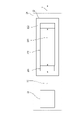
- FIG. 1 is a schematic diagram showing the configuration of the device 1 according to the first embodiment.
- the device 1 includes an object mounting unit 10, a light irradiation unit 20, a photodetector 30, a condenser lens 50, an imaging lens 40, and a control unit 60.
- the target mounting portion 10 is a plate-shaped guide for restricting the measurement target portion Mp of the living body Ob to a predetermined position and angle suitable for measurement by abutting the surface of the skin of the living body Ob on the surface 10a. It is a member. In this case, the surface 10a of the target mounting portion 10 becomes the living body mounting surface.
- an optical system such as a light irradiation unit 20 with a housing (not shown) and providing the target mounting portion 10 on the outer shell portion of the housing, the target mounting portion 10 is lasered from the inside. It can function as an irradiation window (window) to which the light L1 is irradiated.
- the target mounting portion 10 is made of a material transparent to mid-infrared light, for example, ZnSe, as a specific wavelength used for measurement, and may be provided with a non-reflective coating layer on the surface.
- the measurement position is marked on the surface 10a of the target mounting portion 10, and the living body Ob is placed at a predetermined pressure in the target mounting portion 10 in a state where the living body Ob containing the measurement target portion Mp is aligned with the measurement position.
- a state in which the measurement target portion Mp, which is a portion of the living body located inward from the epidermis such as the dermis, is separated from the surface 10a of the target mounting portion 10 by contacting the surface 10a. Can be held in.
- the target mounting portion 10 is arranged so that the laser light L1 irradiated from the light irradiation unit 20 enters light from the back surface 10d side, and the incident angle ⁇ of the optical axis L1 on the incident side of the front surface 10a is predetermined.
- the relative angle with the light irradiation unit 20 is regulated so as to be the angle of.
- the incident angle ⁇ refers to the angle of the optical axis L1 with respect to the normal line with respect to the surface 10a on which the living body Ob is placed in the target mounting portion 10.
- FIG. 2 (a) and 2 (b) are enlarged cross-sectional views showing an aspect of part A in FIG.
- FIG. 3 is an enlarged view showing a portion where the measurement target portion Mp of the living body Ob is in contact with the target mounting portion 10.
- a recessed portion 10b may be formed on the surface 10a of the target mounting portion 10 so as to form a gap between the target mounting portion 10 and the living body Ob.
- the laser light L1 emitted from the light irradiation unit 20 passes through the bottom surface portion of the recessed portion 10b in the target mounting portion 10 and is irradiated to the surface of the living body Ob. Since the target mounting portion 10 is not opened, it is possible to prevent dust, dirt, water vapor, etc. from entering the atmosphere where the optical system such as the light irradiation portion 20 exists, and the target mounting portion 10 is provided with a dustproof function. be able to.
- the recessed portion 10b By providing the recessed portion 10b, an air layer is formed between the surface 10a of the target mounting portion 10 and the living body Ob, and the surface of the living body Ob is compared with the case where the air layer is brought into contact with the target mounting portion 10. Total internal reflection can be suppressed. Further, by providing the recessed portion 10b, the living body Ob can be more easily adhered to the surface 10a of the target mounting portion 10 in the portion other than the recessed portion 10b except for the portion other than the recessed portion 10b.
- the thickness of the target mounting portion 10 may be 500 ⁇ m
- the width of the recessed portion 10b may be 700 ⁇ m
- the thickness of the air layer in the recessed portion 10b may be about 400 ⁇ m.
- an opening 10c may be formed on the surface 10a of the target mounting portion 10 in a region in contact with the surface of the living body Ob.
- the laser beam L1 emitted from the light irradiation unit 20 by the opening 10c irradiates the surface of the living body Ob through the opening 10c which is a through hole formed in the target mounting portion 10.
- an air layer can be formed at the portion where the surface 10a of the target mounting portion 10 is in contact with the living body Ob, and the living body Ob is compared with the case where the target mounting portion 10 is brought into contact with the air layer. Total internal reflection on the surface can be suppressed. Further, by providing the opening 10c, the living body Ob can be easily adhered to the surface 10a of the target mounting portion 10 around the opening 10c of the surface 10a.
- the thickness of the target mounting portion 10 may be 500 ⁇ m
- the width of the opening 10b may be 700 ⁇ m.
- the light irradiation unit 20 is a light source that irradiates a living body with a laser beam having a specific wavelength toward the measurement target portion Mp.
- the light irradiation unit 20 is arranged on the back surface 10d side of the biological mounting surface 10a of the target mounting unit 10, and the target mounting unit is arranged from the back surface 10d side of the target mounting unit 10.
- a laser beam is irradiated toward the measurement target portion Mp of the living body Ob on the living body mounting surface (surface 10a) of 10.
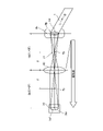
- FIG. 3 is a schematic diagram showing the configuration of the light irradiation unit 20 in the blood substance concentration measuring device 1.
- the light irradiation unit 20 has a light source 21 that oscillates a pump light L0 having a wavelength shorter than that of pulsed mid-infrared light, and converts the light into a long wavelength and amplifies the light L1 to emit the laser light L1.
- It has an optical parametric oscillator 22 (OPO: Optical Parametric Oscillator).
- OPO Optical Parametric Oscillator
- the light irradiation unit 20 outputs the idler light as laser light L1 in the subsequent stage and uses it for measuring the blood glucose level.
- the optical parametric oscillator 22 the configuration described in a known document, for example, Japanese Patent Application Laid-Open No. 2010-281891 may be used.
- the wavelength oscillated by the optical parametric oscillation mid-infrared light is used as the wavelength that is absorbed by glucose more than the conventionally used near-infrared light, and is set to 9.26 ⁇ m in this embodiment.
- this mid-infrared light has a lower transmittance into the body than the near-infrared light conventionally used for measuring blood glucose level, only the epidermis part is observed, and other deep infrared light is observed.
- the effect of being less susceptible to the effects of biological components can be obtained.
- the effect that the overtones of the reference vibration and the overlapping of the combined sounds have little adverse effect on the measurement can be obtained.
- the light source 21 may be provided with a Q-switch Nd: YAG laser (oscillation wavelength 1.064 ⁇ m) or a Q-switch Yb: YAG laser (oscillation wavelength 1.030 ⁇ m).
- the pump light L0 having a shorter wavelength than the mid-infrared light can be oscillated in a pulse shape.
- the pump light L0 may have a pulse width of about 8 ns and a frequency of 10 Hz or more, for example.
- the light source 21 since the light source 21 operates as a passive Q-switch that passively performs a switching operation using a hypersaturated absorber, the light source 21 can be simplified and miniaturized.
- the optical parametric oscillator 22 includes an incident side semitransparent mirror 221, an emitting side semitransparent mirror 222, and a nonlinear optical crystal 223, and is an optical resonator in which the incident side semitransparent mirror 221 and the emitting side semitransparent mirror 222 are opposed to each other.
- a nonlinear optical crystal 223 is arranged therein.
- the light L01 transmitted through the incident side semitransparent mirror 221 is incident on the nonlinear optical crystal 223 and converted into light having a wavelength of 9.26 ⁇ m determined by the nonlinear optical crystal 223, and the incident side semitransparent mirror 221 and the outgoing side semitransparent mirror 222 are converted into light.
- Optical parametric amplification is performed between and.
- the amplified light passes through the emitting side semitransparent mirror 222 and is output as laser light L1.
- the nonlinear optical crystal 223 AgGaS suitable for wavelength conversion is used under the condition of phase matching.
- the wavelength of the oscillated laser beam L1 can be adjusted by adjusting the type and matching conditions of the nonlinear optical crystal 223.
- the nonlinear optical crystal GaSe, ZnGeP 2 , CdSiP 2 , LiInS 2 , LiGaSe 2 , LiInSe 2 , LiGaTe 2 and the like may be used.
- the laser beam L1 emitted from the optical parametric oscillator 22 has a repetition frequency corresponding to the pump light L0, for example, a pulse width of about 8 ns, and a peak output of 10 W to 1 kW can be realized by a short pulse width.
- the light irradiation unit 20 by using the light source 21 and the optical parametric oscillator 22, compared with a conventional light source having a wavelength of 9.26 ⁇ m such as a quantum cascade laser, 10 3 to 10 5 It is possible to obtain a laser beam L1 having about twice as high intensity.
- the optical path Op1 of the laser beam L1 from the light irradiation unit 20 to the measurement target portion Mp is a condensing lens 50 for condensing the irradiation light on the measurement target portion Mp of the living body Ob (the present specification). In the book, it may be referred to as "second lens").
- the laser beam L1 propagates in a space such as in a gas except for a section passing through the condenser lens 50. It is configured.
- the laser light L1 emitted from the light irradiation unit 20 corresponds to the measurement target portion Mp of the living body Ob, for example, the dermis, etc.
- the optical design is such that the light is focused to a depth corresponding to the living body located inward from the dermis.
- the incident angle ⁇ of the laser beam L1 on the measurement target portion Mp is determined by the angle of the light irradiation unit 20 with respect to the surface 10a of the target mounting portion 10 and the refraction angle of the laser light L1 incident on the target mounting portion 10.
- the incident angle ⁇ may be, for example, 45 degrees or more, and further may be 60 degrees or more and 70 degrees or less.
- a beam splitter (not shown) composed of a semitransparent mirror is arranged between the light irradiation unit 20 and the condenser lens 50, and a part of the laser beam L1 is branched as a reference signal to detect light for monitoring.
- a device (not shown) may be used to detect a change in the intensity of the laser beam L1 and used for normalization processing of the detection signal in the light detector 30. The output of the photodetector 30 can be compensated based on the fluctuation of the intensity of the laser beam L1.
- the laser light L1 transmitted through the condenser lens 50 passes through the target mounting portion 10 and is incident on the living body Ob, and is scattered or diffusely reflected by passing through the epithelial interstitial tissue of the living body and is mounted on the target again as the reflected light L2. It passes through the placement portion 10 and is radiated toward the light detector 30.
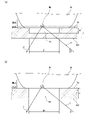
- FIG. 4 is a diagram for explaining an outline of the light path on the light receiving side in the blood substance concentration measuring device 1, and is drawn in a state where the measurement target portion Mp of the living body Ob and the screen 30a of the photodetector 30 are viewed in a plan view. It is a schematic diagram. As shown in FIGS. 1 and 4, in the optical path Op2 of the reflected light L2 from the measurement target portion Mp of the living body Ob to the light detector 30, the reflected light L2 diffusely reflected by the measurement target portion Mp of the living body Ob is emitted.
- An imaging lens 40 (sometimes referred to as a "first lens” in the present specification) for forming an image is arranged on the detector 30.
- the reflected light L2 propagates in a space such as in a gas except for a section passing through the condenser lens 50. It is configured.
- the imaging lens 40 is optical so that the image Im1 in the range corresponding to the measurement target portion Mp of the living body Ob is diffusely reflected and is imaged Im2 on the screen 30a of the photodetector 30 by the imaging lens 40 as reflected light L2. It is designed.
- the distance Op21 between the center of the imaging lens 40 and the measurement target portion Mp of the living body Ob and the distance Op22 between the screen 30a of the photodetector 30 and the center of the imaging lens 40 are set to be equivalent lengths.
- the depth corresponding to the measurement target part Mp of the living body Ob irradiated with infrared light for example, the part of the living body located inward from the dermis such as the dermis (hereinafter, may be referred to as "internal part of the living body").
- the positional relationship is such that the image Im1 is transferred as an image Im2 of an equivalent size on the screen 30a of the photodetector 30.
- the focal length is F with respect to the focal length Fp of the imaging lens 40
- the distance Op21 and the distance Op22 may both be 2F.
- the lengths of the distance Op21 and the distance Op22 are not limited to the above, and the image Im1 of the target mounting portion 10 irradiated with the mid-infrared light is not excessive or deficient in the screen 30a of the photodetector 30.
- the magnification of the distance Op21 and the distance Op22 may be set so as to fit, and the imaging lens 40 that achieves the magnification may be set.
- the angle of incidence of the reflected light L2 on the imaging lens 40 is determined by the angle of the imaging lens 40 with respect to the surface 10a of the target mounting portion 10 and the refraction angle of the reflected light L2 emitted from the target mounting portion 10. In the present embodiment, for example, it may be 0 degrees or more and 40 degrees or less, more preferably 20 degrees or more and 30 degrees or less.
- the photodetector 30 is a mid-infrared sensor that receives the reflected light from the measurement target portion Mp of the irradiated laser light L1 and detects the intensity of the reflected light.
- the photodetector 30 is arranged on the back surface 10d side of the living body mounting surface 10a of the target mounting portion 10, and the living body mounting surface is arranged from the back surface 10d side of the target mounting portion 10.
- (Surface 10a) is configured to receive the reflected light from the measurement target portion Mp in the living body Ob.
- the photodetector 30 outputs an electric signal according to the intensity of the received reflected light.
- an infrared sensor composed of a single element, which outputs the intensity of the reflected light by a one-dimensional voltage value, may be used.
- the intensity of the irradiated laser light L1 is increased by the light irradiation unit 20, and the reflected light reflected from the measurement target portion Mp by the imaging lens 40 is combined on the photodetector 30.
- the photodetector 30 can receive the reflected light having a sufficiently high intensity with respect to the background light, realizes a high S / N ratio, and enables highly accurate measurement.
- the processing required for the light detector 30 is only the detection of the light intensity, and the wavelength is similar to that of the photoacoustic optical method using the quantum cascade laser. There is no need to perform spectral analysis or multivariate analysis based on sweeps. Therefore, the accuracy required for detection is relaxed, and an electronic cooling method or the like that can be easily used can be used.
- an HgCdTe infrared detector cooled with liquid nitrogen may be used. At this time, by cooling to about 77K with liquid nitrogen, the light intensity of the reflected light L2 can be detected with a higher S / N ratio.
- Control unit 60 The control unit 60 is electrically connected to the light irradiation unit 20 and the photodetector 30, drives the light source 21 of the light irradiation unit 20 to oscillate the pulsed pump light L0, and outputs the light from the photodetector 30.
- the light intensity of the reflected light L2 is detected based on the signal, and the glucose concentration in the measurement target portion Mp of the living body Ob is calculated.
- control unit 60 inputs the output of the photodetector for monitoring, and as described above, even if the intensity of the laser light L1 emitted from the light irradiation unit 20 fluctuates, the output of the photodetector for monitoring is output.
- the glucose concentration may be calculated by compensating for the influence of the intensity fluctuation of the laser light L1.
- Test 1 Evaluation of Examples and Comparative Examples of the Blood Substance Concentration Measuring Device 1 [Test equipment, conditions] As an example, the blood substance concentration measuring device 1 according to the embodiment shown in FIG. 1 was used.
- the device conditions of the blood substance concentration measuring device 1 are as follows.
- the image of the measurement target portion Mp of the living body Ob irradiated with the mid-infrared light was transferred by the imaging lens 40 arranged at the lower part of the target mounting portion 10 and imaged on the photodetector 30. ..
- the focal length of the imaging lens 40 is F
- the distance between the screen 30a of the light detector 30 and the center of the imaging lens 40 and the distance between the center of the imaging lens 40 and the measurement target portion Mp of the living body Ob are both. It was set to 2F, and the positional relationship was such that the image Im1 at a depth corresponding to the part of the living body located inward from the epidermis, which corresponds to the measurement target portion Mp, was transferred to the optical detector 30 with a size equivalent to that.
- the angle of the optical path Op2 of the photodetector 30 and the imaging lens 40 was set to an angle inclined by 25 degrees clockwise from the vertical direction of the target mounting portion 10.
- Test method (1) The subject ingested an aqueous solution containing 40 g of glucose (the ingestion time is 0 minutes as the measurement start time), and the subject's fingertip was placed on the upper surface 10a of the target mounting portion 10, and the examples and comparative examples were placed.
- the optical measurement was continuously performed by.
- the blood glucose level was calculated from the change in the intensity of the mid-infrared light when the human body was irradiated with the mid-infrared laser light for a certain period of time.
- SMBG Blood glucose level measurement
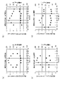
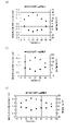
- 5 (a) to 5 (d) show changes in the glucose concentration measured by the photodetector of the conventional device 1X and changes in the glucose concentration measured by the invasive measuring device according to the comparative example. It is the figure which compared with the series. 6 (a) to 6 (d) show the correlation between the measurement result of the glucose concentration by the photodetector and the measurement result of the glucose concentration by the invasive measuring device in FIGS. 5 (a) to 5 (d). It is a figure.
- FIGS. 5 (a) to 5 (d) are the results of tests conducted on the same subject on different test days.
- the blood glucose level due to SMBG rises and then falls with the passage of time after ingesting the aqueous solution.
- the light intensity detected by light measurement is the result of measurement of blood glucose level by SMBG, in which light absorption accompanying an increase in blood glucose concentration causes the ingestion of an aqueous solution, followed by a decrease and an increase with the passage of time. And negative correlation was confirmed (Fig. 6 (a)).
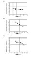
- FIGS. 7 (a) to 7 (c) show changes in the glucose concentration measured by the optical detector of the blood substance concentration measuring device 1 and changes in the glucose concentration measured by the invasive measuring device in chronological order. It is a comparison figure. 8 (a) to 8 (c) show the measurement results of the glucose concentration by the photodetector and the measurement results of the glucose concentration by the invasive blood glucose concentration measuring device in FIGS. 7 (a) to 7 (c). It is a figure which shows the correlation.
- FIGS. 7 (a) to 7 (c) are the results of tests conducted on the same subject on different test days.
- FIGS. 7 (a) to 7 (c) the detected light intensity by measurement is increased after ingesting an aqueous solution due to light absorption accompanying an increase in blood glucose concentration, and then decreases with the passage of time, and the blood glucose level by SMBG increases.
- a high negative correlation was confirmed in FIG. 8 (b)
- a negative correlation was also confirmed in FIGS. 8 (a) and 8 (c).
- FIG. 9 is a schematic diagram of an experimental device for measuring a glucose concentration measurement value by a photodetector by changing the angle of the optical path on the light receiving side and the optical path length in the blood substance concentration measuring device 1.
- the angle ⁇ (hereinafter, may be referred to as “angle ⁇ ”) of the optical path Op2 of the optical detector 30 and the imaging lens 40 is set as the target mounting unit.
- Optical measurement was performed under the condition that the normal degree to the surface on which the living body Ob in No. 10 was placed was different from 0 degrees to 40 degrees clockwise (vertically in FIG. 9).
- Other equipment conditions and test methods are the same as in Test 1.
- [Test results] 10 (a) and 10 (b) are diagrams showing changes in the measured value of glucose concentration when the light receiving angle of the photodetector is changed in the blood substance concentration measuring device 1, and FIG. 10 (a) is a diagram showing an angle ⁇ . The relationship between the and the input / output ratio of the detected light in the optical measurement, (b) is an experimental result showing the variation of the measurement result for each measurement frequency at each angle ⁇ .
- the variation was small at an angle ⁇ of 0 degrees, the variation was the smallest at 25 degrees, and the variation was the largest at 45 degrees.
- the angle ⁇ is 45 degrees or more, it is considered that the angle approaches the specular reflection angle of the incident light.
- the angle ⁇ is 45 degrees or more, it is difficult to measure due to the equipment configuration. In the range where the angle ⁇ is less than 20 degrees, the light receiving side optical system and the emitting side optical system are close to each other, so that it is considered difficult to lay out the optical system of the blood substance concentration measuring device 1.
- the angle ⁇ of the optical path on the light receiving side is preferably 0 degrees or more and 40 degrees or less, and even more preferably 20 degrees or more and 30 degrees or less. Further, in order to suppress the influence of the specular reflection of the incident light, it is preferable that the incident angle of the laser beam is different from the emission angle to the photodetector.
- Distance L (hereinafter, may be referred to as “optical path length L”) is 2F-0.5 [mm], 2F [mm], 2F + 0.5 [mm] with respect to the focal length F of the imaging lens 40.
- Optical measurement was performed under different conditions. Other equipment conditions and test methods are the same as in Test 1.
- [Test results] 11 (a) and 11 (b) show the change in the glucose concentration measured by the light detector when the length of the light path on the light receiving side is changed in the blood substance concentration measuring device 1, and the glucose concentration by the invasive measuring device. It is a figure which compared the change of the measured value of with the time series.
- the detected light intensity by measurement is as described above, in FIG. 7A, the time after ingesting the aqueous solution by light absorption accompanying the increase in blood glucose concentration. It decreased with the passage of time and then increased, and when compared with the measurement result of the blood glucose level by SMBG, a high negative correlation was confirmed in FIG. 8 (a).
- the detected light intensity by measurement is blood as shown in FIGS. 11 (a) and 11 (b). Due to the light absorption accompanying the increase in the medium glucose concentration, there was no tendency for the aqueous solution to be ingested, then decreased with the passage of time, and then increased. In 11 (b), almost no reaction due to the change in blood glucose level was observed. In addition, the result was that the correlation with the measurement result of the blood glucose level by SMBG was low (FIGS. 12 (a) and 12 (b)).
- the optical path length L on the light receiving side that is, the distance L between the screen 30a of the photodetector 30 and the center of the imaging lens 40 and the distance between the center of the imaging lens 40 and the measurement target portion Mp of the living body Ob. It is considered preferable that L has a length corresponding to the imaging position (twice the focal length F) of the imaging lens 40. It is considered that the reflected light from the measurement target portion Mp of the living body Ob corresponding to the living body portion located inward from the epidermis is imaged on the screen 30a of the photodetector 30. At this time, the distance between the upper surface 10a of the object mounting portion 10 corresponding to the skin surface and the center of the imaging lens 40 was about 50 mm, which was about 0.8 mm shorter than the distance L.
- the correlation with the measurement result of the blood glucose level by SMBG is higher than that of the conventional device 1X according to the comparative example, and the reproducibility is high. It was confirmed that high measurement results were obtained.
- an imaging lens 40 is provided between the measurement target portion Mp and the light detector 30, and the reflected light L2 reflected from the measurement target portion Mp is imaged on the light detector 30. It is considered that the adoption of the optical system with the above configuration made it possible to measure light with high reproducibility.
- the conventional device 1X using the waveguide according to the comparative example cannot separate the component from the skin surface and the component absorbed by blood glucose under the skin, and the condition of the skin surface and the slight amount of laser are used.
- normal measurement could not be performed due to changes in irradiation conditions, etc.
- signals from under the skin are collected on the optical sensor, so that the measurement conditions are met. It is probable that the influence of slight changes on the measurement results has decreased, and stable and correct measurement results can be obtained.
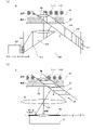
- FIG. 13A is a schematic diagram showing an outline of the optical path from the light irradiation unit 20X to the photodetector 30X in the conventional blood substance concentration measuring device 1X.
- the laser light LX1 irradiated from the light irradiation unit 20 is parallel to the incident side waveguide 91X, and the measurement target portion Mp of the living body Ob.
- the reflected light component (Im11) in the inward portion of the living body below the skin surface that should be the measurement target that can be absorbed by blood glucose the reflected light component (Im12) from the skin surface is generated.
- these reflected light components (Im11, Im12) are configured to enter light into the emitting side waveguide 92X and be guided to the screen 30Xa of the photodetector 30. ..
- the reflected light component (Im12) from the skin surface and the reflected light component (Im11) in the inward portion of the living body below the skin surface are not separated, and both components are mixed by the photodetector. Detected.
- the measurement result includes a reflected light component (Im12) other than the reflected light component (Im11) in the inner part of the living body below the skin surface to be measured, fluctuation factors increase and the reproducibility is low. It is thought that it became.
- FIG. 13B is a schematic diagram showing an outline of the optical path from the light irradiation unit 20 to the photodetector 30 in the blood substance concentration measuring device 1.
- the laser light L1 irradiated from the light irradiation unit 20 is similarly the living body Ob along the optical path toward the inspection target portion Mp of the living body Ob.
- the reflected light component (Im11) in the inward part of the living body below the skin surface that should be absorbed by blood glucose and become the measurement target part Mp the reflected light component (Im12) from the skin surface Occur.
- the image pickup lens 40 allows the reflected light component (Im11) mainly in the inner part of the living body among these reflected light components (Im11, Im12) to be the photodetector 30. It is configured to be imaged on the screen 30a.
- the reflected light component (Im12) from the skin surface enters the imaging lens 40, but since the angle of incidence on the imaging lens 40 is different from the reflected light component (Im11) in the inner part of the living body, light detection is performed.
- the reflected light component (Im11) in the inward portion of the living body below the skin surface, which should be mainly measured, is imaged on the screen 30a of the photodetector 30 and is a photodetector. Since it is reflected in the optical measurement by 30, it is considered that the measurement result has a high correlation with the measurement result of the blood glucose level by SMBG and has high reproducibility as compared with the comparative example.
- the blood substance concentration measuring device 1 can reduce the false signal (noise) component due to the reflected light scattered on the skin surface as compared with the conventional device 1X using the waveguide, and can measure the light. S / N ratio can be improved. Further, for this reason, it is possible to always perform highly accurate optical measurement regardless of the state of the skin surface that fluctuates depending on the subject and the measurement. Further, it is possible to obtain an effect that the optical path length L on the light receiving side can be changed by adjusting the position of the photodetector to cope with a measurement target having a thick skin.
- the blood substance concentration measuring device 1 is a blood substance concentration measuring device 1 for measuring the concentration of a substance contained in the blood of the living body Ob, and is the living body Ob.
- the light irradiation unit 20 that irradiates the measurement target portion Mp with the laser beam L1 from the target mounting portion 10 on which the measurement target portion Mp is placed and the back surface 10d side of the biological mounting surface (front surface 10a) of the target mounting portion 10.
- the light detector 30 that receives the reflected light L2 from the measurement target portion Mp of the laser light L1 irradiated on the back surface 10d side of the target mounting portion 10 and detects the intensity of the reflected light L2, and the measurement target portion.
- An imaging lens 40 is provided between the Mp and the light detector 30, and the laser beam L2 is provided in the section from the target mounting portion 10 to the light detector 40 in the optical path Op2 from the measurement target portion Mp to the light detector 30. Propagates in space except for a section passing through the imaging lens 40, and the imaging lens 40 is characterized in that the reflected light L2 reflected from the measurement target portion Mp is imaged on the light detector 30. ..
- the blood substance concentration measuring device 1 includes a target mounting unit 10, a light irradiation unit 20, a photodetector 30, and an imaging lens 40, and the imaging lens 40 is a measurement target portion.
- the reflected light L2 reflected from the Mp is formed into an image on the photodetector 30.
- the specific configuration for the imaging lens 40 to form an image of the reflected light L2 reflected from the measurement target portion Mp on the photodetector 30 is not limited to these, and may be another embodiment. good.
- FIG. 14 is a schematic diagram showing the configuration of the blood substance concentration measuring device 1A according to the second embodiment.
- the same configuration as that of the blood substance concentration measuring device 1 is assigned the same number, and the description thereof will be omitted.
- the relative positional relationship with respect to the measurement target portion Mp is equivalent to that of the light detector 30.
- a two-dimensional imaging means that receives the reflected light (Im11) reflected from the measurement target portion Mp and detects whether or not an image based on the reflected light (Im11) is formed. It differs from the first embodiment in that it is provided with 71A.
- the two-dimensional image pickup means 71A is a two-dimensional infrared image pickup element array in which a plurality of light receiving elements capable of detecting mid-infrared light are arranged in a matrix on the light receiving surface 71Aa. As shown in FIG. 14, the two-dimensional imaging means 71A is integrated with the photodetector 30 to form a photodetector unit 70A, and the optical path of the photodetector unit 70A from the measurement target portion Mp to the imaging lens 40. It is configured to be slidable in the direction perpendicular to L2.
- the relative positional relationship of the light receiving surface 71Aa of the two-dimensional image pickup means 71A with respect to the measurement target portion Mp is the screen of the photodetector 30 with respect to the measurement target portion Mp. They are arranged so as to be equivalent to the relative positional relationship of 30a.
- the photodetector 30 performs a step of adjusting the optical path length from the measurement target portion Mp to the photodetector 30 in order to form an image of the reflected light (Im11) from the measurement target portion Mp on the photodetector 30.
- FIG. 15 is a schematic diagram for explaining an operation of adjusting the optical path length from the measurement target portion Mp to the photodetector 30 by the blood substance concentration measuring device 1A.
- the relative positional relationship of the light receiving surface 71Aa of the two-dimensional imaging means 71A with respect to the measurement target portion Mp on the optical path L2 is the light detection with respect to the measurement target portion Mp. It is arranged at a position equivalent to the relative positional relationship of the screen 30a of the vessel 30.
- the two-dimensional image pickup means 71A receives the reflected light reflected from the measurement target portion Mp, detects whether or not an image based on the reflected light is formed, and forms an image. If not, the position of the two-dimensional image pickup means 71A on the optical path L2 is gradually moved, and the detection of whether or not an image is formed is repeated.
- the focus position of the image in the memory changes by scanning the two-dimensional imaging means 71A along the optical path L2. This is determined by image analysis, and the position of the two-dimensional image pickup means 71A when the irradiation position and the focus position examined in advance match is determined as the image formation position.
- a scale with a scale of 0.5 mm increments is mounted on the target mounting portion 10, and an image is acquired by the two-dimensional imaging means 71A. This is done by detecting the focus position in the image.
- the focus position may be the maximum point of the luminance distribution in the image.
- the photodetection unit 70A is gradually moved in parallel with the optical path L2 until the focus position in the acquired image and the irradiation position of the laser beam L1 coincide with each other on the optical path L2, and the presence or absence of an image formation is determined.
- the two-dimensional image pickup means 71A is returned to the photodetector 30, and the optical path length from the measurement target portion Mp to the photodetector 30 is determined.
- the measurement target portion is configured so that the relative positional relationship with respect to the measurement target portion Mp can be arranged so as to be equivalent to the photodetector 30.
- the configuration is provided with a two-dimensional image pickup means 71A that receives the reflected light (Im11) reflected from the Mp and detects whether or not an image based on the reflected light (Im11) is formed.
- the photodetector 30 performs the step of adjusting the optical path length from the measurement target portion Mp to the photodetector 30 in order to form an image of the reflected light (Im11) from the measurement target portion Mp on the photodetector 30. It can be replaced with the two-dimensional imaging means 71A. As a result, it is possible to easily construct the blood substance concentration measuring device 1A capable of stably performing highly accurate measurement regardless of the state of the measurement target and the fluctuation of the irradiation condition of the laser beam.
- Embodiment 3 In the blood substance concentration measuring devices 1 and 2 according to the first embodiment, the wavelength of the laser beam L1 emitted by the light irradiation unit 20 is 9.26 ⁇ m, and the blood component to be detected is glucose.
- the wavelength of the laser beam L1 emitted by the light irradiation unit 20 may be different depending on the type of blood component to be detected.
- the wavelength of the laser beam L1 emitted by the light irradiation unit 20 may be 8.23 ⁇ 0.05 ⁇ m (8.18 ⁇ m or more and 8.28 ⁇ m or less), and the blood component may be set. Is characterized by being lactic acid.
- the wavelength may range from 5.77 ⁇ m, 6.87 ⁇ m, 7.27 ⁇ m, 8.87 ⁇ m, or 9.55 ⁇ m to ⁇ 0.05 ⁇ m or more and +0.05 ⁇ m or less.
- FIG. 16 is a diagram showing changes in the measured value of lactic acid concentration by a photodetector when the wavelength of the light emitted by the light irradiation unit 20 is 8.23 ⁇ m in the blood substance concentration measuring device according to the third embodiment. be. As shown in FIG. 16, it was confirmed that the measured value by optical measurement generally correlates with the measurement result (comparative value) of the lactate value by self-collecting blood.
- the apparatus can be realized by changing the optical parametric oscillator 22 having different phase matching conditions of the nonlinear crystal 223.
- a plurality of types of blood components can be selectively used by selectively using a plurality of optical parametric oscillators 22 and adopting a device configuration capable of selectively irradiating laser light L1 having a plurality of wavelengths. May be a device capable of measuring.
- the blood substance concentration measuring device is different from the configuration that employs an optical system using a waveguide in which the width and thickness of the optical path differ depending on the wavelength of the light to be guided, for example, glucose.
- An optical system including a condenser lens 50, an object mounting portion 10, an imaging lens 40, and a light detector 30 capable of detecting mid-infrared light can be shared with a measuring device for other blood components such as. ..
- the blood substance concentration measuring device it is possible to detect different types of blood components by changing the wavelength of the laser beam L1 emitted by the light irradiation unit 20.
- a plurality of types of different blood components can be detected by selectively irradiating laser light L1 having different wavelengths with the same measuring device.
- the embodiment of the blood substance concentration measuring device is shown by taking as an example an optical system provided with an imaging lens 40 between the measurement target portion Mp and the photodetector 30.
- the blood substance concentration measuring device according to the present disclosure may be configured to form an image of the reflected light L2 reflected from the measurement target portion Mp of the living body Ob on the photodetector 30, and may be optical on the light receiving side.
- the system may be appropriately modified to another embodiment. For example, a configuration using a plurality of lenses or a configuration in which a mirror is arranged in the middle of the optical path may be used.
- the embodiment is shown by taking glucose or lactic acid as an example of the blood component to be detected by the blood substance concentration measuring device.
- the detectable blood component of the blood substance concentration measuring device according to the present disclosure is not limited to the above, and the wavelength of the laser light L1 emitted by the light irradiation unit 20 is set according to the type of the blood component. By making them different, the device can be widely used for other detection targets.
- the photodetector 30 shows the embodiment by taking as an example an infrared sensor composed of a single light receiving element capable of detecting mid-infrared light.
- the photodetector 30 may be a two-dimensional infrared image pickup element array in which a plurality of light receiving elements capable of detecting mid-infrared light are arranged in a matrix on the light receiving surface.
- the step of adjusting the optical path length from the measurement target portion Mp to the photodetector 30 for forming an image of the reflected light from the measurement target portion Mp on the photodetector 30 is performed by using the photodetector 30 itself. It will be possible to do.
- the photodetector 30 receives the reflected light reflected from the measurement target portion Mp, and detects whether or not an image based on the reflected light is formed.
- the position of the photodetector 30 on the optical path L2 is gradually moved, and the detection of whether or not the image is formed is repeated.
- the step of adjusting the optical path length from the measurement target portion Mp to the photodetector 30 can be performed using the photodetector 30 itself, and the apparatus can be simplified as compared with the second embodiment.
- the light irradiation unit 20 emits laser light from the back surface 10d side of the biological mounting surface (front surface 10a) of the target mounting unit 10 to the measurement target portion Mp.
- the photodetector 30 is configured to irradiate L1 and receive the reflected light L2 from the measurement target portion of the laser light L1 irradiated on the back surface 10d side of the target mounting portion 10.
- the light irradiation unit 20 may be configured to irradiate the measurement target portion Mp with the laser beam L1 from the surface 10a side of the biological mounting surface (surface 10a) of the target mounting unit 10.
- the photodetector 30 may be configured to receive the reflected light L2 from the measurement target portion of the laser beam L1 irradiated on the surface 10a side of the target mounting portion 10.
- the measurement target portion Mp of the living body Ob is placed upward on the target placing portion 10, and the living body Ob is slightly compressed from above on the plate material through which the laser light L1 is transmitted (transparent to the laser light).
- the height of the measurement target portion Mp with respect to the target mounting portion 10 (and the light irradiation portion 20) may be defined.
- an optical means for detecting the position of the measurement target portion Mp by irradiating the laser beam and measuring the time until the reflected light from the measurement target portion Mp of the living body Ob is received is provided, and the detected measurement target is detected. It may be configured to provide feedback such as different irradiation directions and focusing distances of the laser beam L1 in the measurement of the blood substance concentration based on the position information of the partial Mp.
- the light irradiation unit 20 irradiates the measurement target portion Mp with the laser beam L1 from the surface 10a side of the living body mounting surface (surface 10a) without passing through the target mounting portion 10 to measure the blood substance concentration. Can be done.
- the order in which the above method is executed is for exemplifying for concretely explaining the present invention, and may be an order other than the above. Moreover, a part of the above-mentioned method may be executed at the same time (parallel) with another method.
- the blood substance concentration measuring device and the blood substance concentration measuring method according to one aspect of the present disclosure routinely measure blood substance states such as blood glucose level and blood lipid level in the prevention and treatment of lifestyle diseases. It can be widely used as a medical device.
Abstract
A substance-in-blood concentration measurement device 1 for measuring the concentration of a substance contained in the blood of a living body Ob comprises: a target placement part 10 on which a measurement target part Mp of the living body Ob is placed, a light emitting part 20 for emitting a laser beam L1 to the measurement target part Mp, a photodetector 30 for receiving the reflected light of the emitted laser beam from the measurement target part Mp and detecting the intensity of reflected light L2, and an imaging lens 40 between the measurement target part Mp and the photodetector 30. In a segment from the target placement part 10 to the photodetector 30 in an optical path Op2 from the measurement target part Mp to the photodetector 30, the laser beam L2 propagates through a space except for a segment passing through the imaging lens 40, and the imaging lens 40 forms, on the photodetector 30, an image of the reflected light L2 reflected from the measurement target part Mp.
Description
本開示は、生体の血管内を流れる血液に含まれる物質の濃度を非侵襲式の測定方法により測定する装置及び方法に関する。
The present disclosure relates to an apparatus and method for measuring the concentration of a substance contained in blood flowing in a blood vessel of a living body by a non-invasive measuring method.
生活習慣病の予防・治療において、日常的に血糖値、血中脂質値等の血中物質状態を調べることは重要である。なかでも、生活習慣病の一つである糖尿病の患者に対して、合併症を防止するために、血液中に含まれるグルコースの濃度を測定して日常的な血糖値の管理が要求されており、患者から採血を行い血液中の化学分析を行う侵襲法が従来から行われている。
In the prevention and treatment of lifestyle-related diseases, it is important to check the blood substance status such as blood glucose level and blood lipid level on a daily basis. In particular, diabetic patients, one of the lifestyle-related diseases, are required to measure the concentration of glucose contained in the blood and manage their blood glucose levels on a daily basis in order to prevent complications. , An invasive method of collecting blood from a patient and performing a chemical analysis in the blood has been conventionally performed.
これに対し、近年、採血を伴わず体内の血液中の状態を光学的に測定する簡便な非侵襲法が提案されている。例えば、特許文献1には、高強度の中赤外光を導波路を介して生体に照射し、その反射光を導波路を介して光検出器に導光することにより、非侵襲かつ単純な構成で血中グルコース濃度を測定する血中物質濃度測定装置が開示されている。
On the other hand, in recent years, a simple non-invasive method for optically measuring the state of blood in the body without collecting blood has been proposed. For example, Patent Document 1 irradiates a living body with high-intensity mid-infrared light via a waveguide, and guides the reflected light to a photodetector via a waveguide, thereby making it non-invasive and simple. A blood substance concentration measuring device for measuring a blood glucose concentration in the configuration is disclosed.
ところが、特許文献1に記載の、導波路を用いた従来の血中物質濃度測定装置では、計測対象となる生体の皮膚表面の状態や、照射されるレーザー光のわずかな条件の変化などによって測定値が変動し、安定して正常な計測を行うことが難しいという課題があった。
However, in the conventional blood substance concentration measuring device using a waveguide described in Patent Document 1, measurement is performed based on the condition of the skin surface of the living body to be measured, a slight change in the conditions of the irradiated laser beam, and the like. There was a problem that the value fluctuated and it was difficult to perform stable and normal measurement.
本開示は、上記課題に鑑みてなされたものであり、計測対象の状態やレーザー光の照射条件の変動にかかわらず、精度の高い計測を安定して行うことができる血中物質濃度測定装置、及び血中物質濃度測定方法を提供することを目的とする。
The present disclosure has been made in view of the above problems, and is a blood substance concentration measuring device capable of stably performing highly accurate measurement regardless of changes in the state of the measurement target and the irradiation condition of the laser beam. And to provide a method for measuring blood substance concentration.
上記目的を達成するため、本開示の一態様に係る血中物質濃度測定装置は、生体の血液中に含まれる物質の濃度を測定する血中物質濃度測定装置であって、計測対象部分を含む生体が載置される対象載置部と、計測対象部分にレーザー光を照射する光照射部と、照射された前記レーザー光の前記計測対象部分からの反射光を受光して、当該反射光の強度を検出する光検出器と、前記反射光の光路における前記計測対象部分と前記光検出器との間に第1のレンズとを備え、前記計測対象部分から前記光検出器までの光路における前記対象載置部から前記光検出器までの区間において、前記反射光は前記第1のレンズを通過する区間を除いて空間中を伝播し、前記第1のレンズは、前記反射光を光検出器上において結像させることを特徴とする。
In order to achieve the above object, the blood substance concentration measuring device according to one aspect of the present disclosure is a blood substance concentration measuring device for measuring the concentration of a substance contained in the blood of a living body, and includes a measurement target portion. The object placement part on which the living body is placed, the light irradiation part that irradiates the measurement target part with the laser light, and the reflected light from the measurement target part of the irradiated laser light are received and the reflected light of the reflected light is received. The light detector for detecting the intensity and the first lens between the measurement target portion in the optical path of the reflected light and the light detector are provided, and the said in the optical path from the measurement target portion to the light detector. In the section from the object mounting portion to the light detector, the reflected light propagates in space except for the section passing through the first lens, and the first lens transmits the reflected light to the light detector. It is characterized by forming an image on the top.
本開示の一態様に係る血中物質濃度測定装置、及び血中物質濃度測定方法によれば、計測対象の状態やレーザー光の照射条件の変動にかかわらず、精度の高い計測を安定して行うことができる。
According to the blood substance concentration measuring device and the blood substance concentration measuring method according to one aspect of the present disclosure, highly accurate measurement is stably performed regardless of changes in the state of the measurement target and the irradiation conditions of the laser beam. be able to.
≪発明を実施するための形態に至った経緯≫
近年、糖尿病の患者に対する日常的な血糖値の管理等のために、採血を伴わない非侵襲血中物質濃度測定法が提案されており、図17は、特許文献1に開示された、非侵襲法を用いた従来の血中物質濃度測定装置1X(以後、「装置1X」と記す場合がある)の構成を示す模式図である。 << Background to the form for implementing the invention >>
In recent years, a non-invasive blood substance concentration measuring method without blood sampling has been proposed for daily blood glucose control for diabetic patients, and FIG. 17 is a non-invasive method disclosed inPatent Document 1. It is a schematic diagram which shows the structure of the conventional blood substance concentration measuring apparatus 1X (hereinafter, may be abbreviated as "device 1X") using a method.
近年、糖尿病の患者に対する日常的な血糖値の管理等のために、採血を伴わない非侵襲血中物質濃度測定法が提案されており、図17は、特許文献1に開示された、非侵襲法を用いた従来の血中物質濃度測定装置1X(以後、「装置1X」と記す場合がある)の構成を示す模式図である。 << Background to the form for implementing the invention >>
In recent years, a non-invasive blood substance concentration measuring method without blood sampling has been proposed for daily blood glucose control for diabetic patients, and FIG. 17 is a non-invasive method disclosed in
図17に示すように、装置1Xは、検査対象である生体Obが載設される対象載置部10X、中赤外光からなるパルス状のレーザー光L1を照射する光照射部20X、貫通孔からなる入射側導波路91Xと出射側導波路92Xが開設された導光部90X、生体Obからの反射光LX2を受光して強度を検出する光検出器30X、これらの制御部60Xを備える。特許文献1には、装置1Xによれば、高強度の中赤外光を照射することにより、非侵襲かつ単純な構成で血中グルコース濃度を測定できることが記載されている。
As shown in FIG. 17, the apparatus 1X includes a target mounting portion 10X on which a living body Ob to be inspected is placed, a light irradiation portion 20X that irradiates a pulsed laser beam L1 composed of mid-infrared light, and a through hole. It is provided with a light guide unit 90X having an incident side waveguide 91X and an exit side waveguide 92X, a photodetector 30X that receives the reflected light LX2 from the living body Ob and detects the intensity, and a control unit 60X thereof. Patent Document 1 describes that according to the apparatus 1X, the blood glucose concentration can be measured with a non-invasive and simple configuration by irradiating with high-intensity mid-infrared light.
ところが、上述のとおり、非侵襲法を用いた装置1Xでは、計測対象となる生体の皮膚表面の状態や、照射されるレーザー光のわずかな条件の変化などによって測定値が変動し、安定して正常な計測を行うことが難しいことが、発明者らの実験により判明した。
However, as described above, in the device 1X using the non-invasive method, the measured value fluctuates and is stable depending on the condition of the skin surface of the living body to be measured and the slight change in the conditions of the irradiated laser beam. Experiments by the inventors have shown that it is difficult to make normal measurements.
発明者らの検討によれば、皮膚表面からの反射光成分と、本来の測定対象である血糖が含まれる皮膚表面下方の生体内方部分からの反射光成分とが分離されずに、光検出器によって両成分が混じって検出されることが、測定値変動の要因として考えられる。そして、これを解消するために、例えば、被験者の生体条件や測定条件に適合するように被験者や測定ごとに光学系を設定することが必要となる。しかしながら、生体ごとや測定のたびに光学系を適切に調整することは高度な技量を要し、患者自身が日常的に行う血糖値の測定において実施することは、非侵襲法による簡便性を大きく損ねるものとなる。
According to the study by the inventors, the reflected light component from the skin surface and the reflected light component from the inward part of the living body below the skin surface containing blood glucose, which is the original measurement target, are not separated and the light is detected. The fact that both components are mixed and detected by the instrument is considered to be a factor in the fluctuation of the measured value. Then, in order to solve this, for example, it is necessary to set the optical system for each subject and measurement so as to match the biological conditions and measurement conditions of the subject. However, it requires a high degree of skill to properly adjust the optical system for each living body and each measurement, and it is much easier for the patient to measure the blood glucose level on a daily basis by the non-invasive method. It will be a loss.
そこで、発明者らは、非侵襲血中物質濃度測定法において、計測対象の状態やレーザー光の照射条件の変動にかかわらず、精度の高い計測を安定して実現することができる光学系の構成について鋭意検討を行い、以下の実施の形態に至ったものである。
Therefore, in the non-invasive blood substance concentration measurement method, the inventors have configured an optical system capable of stably realizing highly accurate measurement regardless of changes in the state of the measurement target and the irradiation conditions of the laser beam. Diligently studied, and the following embodiments were reached.
≪本発明を実施するための形態の概要≫
本開示の実施の形態に係る血中物質濃度測定装置は、生体の血液中に含まれる物質の濃度を測定する血中物質濃度測定装置であって、計測対象部分を含む生体が載置される対象載置部と、前記計測対象部分にレーザー光を照射する光照射部と、照射された前記レーザー光の前記計測対象部分からの反射光を受光して、当該反射光の強度を検出する光検出器と、前記反射光の光路における前記計測対象部分と前記光検出器との間に第1のレンズとを備え、前記計測対象部分から前記光検出器までの光路における前記対象載置部から前記光検出器までの区間において、前記反射光は前記第1のレンズを通過する区間を除いて空間中を伝播し、前記第1のレンズは、前記反射光を光検出器上において結像させることを特徴とする。 << Outline of the form for carrying out the present invention≫
The blood substance concentration measuring device according to the embodiment of the present disclosure is a blood substance concentration measuring device for measuring the concentration of a substance contained in the blood of a living body, and a living body including a measurement target portion is placed therein. Light that detects the intensity of the reflected light by receiving the reflected light from the target mounting portion, the light irradiation portion that irradiates the measurement target portion with the laser light, and the irradiated portion of the measurement target portion. A first lens is provided between the detector and the measurement target portion in the optical path of the reflected light and the light detector, and from the target mounting portion in the optical path from the measurement target portion to the light detector. In the section to the light detector, the reflected light propagates in space except for the section passing through the first lens, and the first lens forms an image of the reflected light on the light detector. It is characterized by that.
係る構成により、導波路を用いた従来の装置と比較して、皮膚表面で散乱された反射光による偽信号(ノイズ)成分を減少することができ光計測におけるS/N比を向上できる。このため、被験者や測定ごとに変動する皮膚表面の状態によらず、常に確度の高い光計測が可能となる。そのため、計測対象の状態やレーザー光の照射条件の変動にかかわらず、精度の高い計測を安定して行うことができる血中物質濃度測定装置を提供できる。その結果、患者自身が日常的に行う血糖値の測定において、生体ごとや測定のたびに光学系を適切に調整するといった作業を排し、非侵襲かつ簡便な計測法を実現することができる。
With such a configuration, the false signal (noise) component due to the reflected light scattered on the skin surface can be reduced and the S / N ratio in the optical measurement can be improved as compared with the conventional device using the waveguide. Therefore, regardless of the subject and the condition of the skin surface that fluctuates with each measurement, highly accurate optical measurement is always possible. Therefore, it is possible to provide a blood substance concentration measuring device capable of stably performing highly accurate measurement regardless of changes in the state of the measurement target and the irradiation condition of the laser beam. As a result, it is possible to realize a non-invasive and simple measurement method by eliminating the work of appropriately adjusting the optical system for each living body or each measurement in the daily measurement of the blood glucose level by the patient himself / herself.
また、別の態様では、上記何れかの態様において、前記光照射部は、前記対象載置部の生体載置面の裏面側から前記計測対象部分にレーザー光を照射し、前記光検出器は、前記対象載置部の前記裏面側において照射された前記レーザー光の前記計測対象部分からの反射光を受光する構成としてもよい。
In another aspect, in any of the above embodiments, the light irradiation unit irradiates the measurement target portion with laser light from the back surface side of the biological mounting surface of the target mounting portion, and the photodetector. The laser beam irradiated on the back surface side of the object mounting portion may be configured to receive the reflected light from the measurement target portion.
係る構成により、皮膚表面で散乱された反射光による偽信号(ノイズ)成分を減少可能な光計測装置の光学系を実現できる。
With such a configuration, it is possible to realize an optical system of an optical measuring device capable of reducing false signal (noise) components due to reflected light scattered on the skin surface.
また、別の態様では、上記何れかの態様において、前記計測対象部分は、表皮より内方に位置する前記生体の部分であり、前記第1のレンズは、前記計測対象部分における前記レーザー光の照射領域を検出器の受光面上に転送させる構成としてもよい。
In another aspect, in any of the above embodiments, the measurement target portion is a portion of the living body located inward from the epidermis, and the first lens is a portion of the laser beam in the measurement target portion. The irradiation area may be transferred onto the light receiving surface of the detector.
係る構成により、ノイズとして検出される皮膚表面からの反射光成分の光計測への影響度は小さなものとなり、主に計測対象部分となるべき皮膚表面下方の生体部分における反射光成分が、光検出器のスクリーンに結像されて光検出器による光計測に反映される。そのため、再現性が高い計測を行うことができる。
With this configuration, the influence of the reflected light component from the skin surface detected as noise on the light measurement is small, and the reflected light component in the biological part below the skin surface, which should be the measurement target part, is detected as light. It is imaged on the screen of the device and reflected in the light measurement by the photodetector. Therefore, it is possible to perform measurement with high reproducibility.
また、別の態様では、上記何れかの態様において、さらに、前記レーザー光の光路における前記光照射部と前記計測対象部分との間に位置し、前記レーザー光を前記計測対象部分に集光させる第2のレンズを備え、前記光照射部から前記計測対象部分までの光路における前記光照射部から前記対象載置部までの区間において、前記レーザー光は前記第2のレンズを通過する区間を除いて空間中を伝播する構成としてもよい。
In another aspect, in any of the above embodiments, the laser beam is further located between the light irradiation portion and the measurement target portion in the optical path of the laser light, and the laser light is focused on the measurement target portion. A second lens is provided, and in the section from the light irradiation section to the target mounting section in the optical path from the light irradiation section to the measurement target portion, the laser beam excludes the section passing through the second lens. It may be configured to propagate in space.
係る構成により、光照射部から出射されたレーザー光が、対象載置部の表面から所定の距離に離間した計測対象部分に該当する、表皮より内方に位置する生体の部分に相当する深度に集光されることができる。このとき、計測対象部分に応じたサイズにレーザー光の照射範囲を縮小することができる。
With this configuration, the laser beam emitted from the light irradiation unit has a depth corresponding to the portion of the living body located inward from the epidermis, which corresponds to the measurement target portion separated from the surface of the target mounting portion by a predetermined distance. Can be focused. At this time, the irradiation range of the laser beam can be reduced to a size corresponding to the measurement target portion.
また、別の態様では、上記何れかの態様において、前記光検出器の受光面は皮膚表面における反射光の結像位置よりも、所定距離だけ前記第1のレンズから離間している構成としてもよい。
In another aspect, in any of the above embodiments, the light receiving surface of the photodetector may be separated from the first lens by a predetermined distance from the image formation position of the reflected light on the skin surface. good.
係る構成により、表皮より内方に位置する生体の部分に相当する前記計測対象部分における光の照射領域を検出器の位置に転送させることができる。
With such a configuration, the light irradiation region in the measurement target portion corresponding to the portion of the living body located inward from the epidermis can be transferred to the position of the detector.
また、別の態様では、上記何れかの態様において、前記光検出器の位置を異ならせて、前記計測対象部分の皮膚表面からの深さを異ならせる構成としてもよい。
Further, in another aspect, in any of the above embodiments, the position of the photodetector may be different so that the depth of the measurement target portion from the skin surface may be different.
係る構成により、光検出器の位置調整により受光側の光路長Lを変えて、皮膚の厚みが大きい測定対象にも対応することができる。
With this configuration, the optical path length L on the light receiving side can be changed by adjusting the position of the photodetector, and it is possible to handle a measurement target with a large skin thickness.
また、別の態様では、上記何れかの態様において、前記レーザー光の前記計測対象部分への入射角度は、前記計測対象部分から前記光検出器への光路の出射角度と異なる構成としてもよい。
In another aspect, in any of the above embodiments, the angle of incidence of the laser beam on the measurement target portion may be different from the emission angle of the optical path from the measurement target portion to the photodetector.
係る構成により、入射光の正反射の影響を受けることを抑制することができる。
With such a configuration, it is possible to suppress the influence of specular reflection of incident light.
また、別の態様では、上記何れかの態様において、前記計測対象部分から前記光検出器への光路の出射角度は、前記対象載置部における前記生体が載置される面に対する法線を基準に0度以上90度以下であり、かつ、前記法線を基準とした前記レーザー光の前記計測対象部分への入射角度と相違する構成としてもよい。
In another aspect, in any of the above embodiments, the emission angle of the optical path from the measurement target portion to the photodetector is based on the normal to the surface on which the living body is placed in the target mounting portion. The configuration may be such that the temperature is 0 degrees or more and 90 degrees or less, and the angle of incidence of the laser beam on the measurement target portion with respect to the normal line is different.
また、別の態様では、上記何れかの態様において、前記レーザー光の前記計測対象部分への入射角度は、前記対象載置部における前記生体が載置される面に対する法線を基準に45度以上であり、前記計測対象部分から前記光検出器への光路の出射角度は、前記法線を基準に0度以上40度以下である構成としてもよい。
In another aspect, in any of the above embodiments, the angle of incidence of the laser beam on the measurement target portion is 45 degrees with respect to the normal to the surface on which the living body is placed in the target mounting portion. As described above, the emission angle of the optical path from the measurement target portion to the photodetector may be 0 degrees or more and 40 degrees or less with respect to the normal.
係る構成により、グルコースによる光吸収が相対的に大きく、正反射による信号の増大がなく、かつ、受光側光学系と出射側光学系を構築可能な範囲において、安定した測定が可能な光学系が実現できる。
With this configuration, an optical system capable of stable measurement is provided within a range in which light absorption by glucose is relatively large, signal increase due to specular reflection does not occur, and an optical system on the light receiving side and an optical system on the emitting side can be constructed. realizable.
また、別の態様では、上記何れかの態様において、前記レーザー光の波長は、2.5μm以上12μm以下の範囲から選択される所定の波長である構成としてもよい。
Further, in another aspect, in any of the above embodiments, the wavelength of the laser beam may be a predetermined wavelength selected from the range of 2.5 μm or more and 12 μm or less.
係る構成により、従来用いられていた近赤外光に比べてグルコースによる吸収が大きく、血中グルコース濃度を計測することができる。また、従来、血糖値の測定に用いられていた近赤外光に比べて体内への透過率が低いために、表皮部分のみを観測することになり、皮膚深部に存在する他の生体成分の影響を受けにくいという効果が得られる。
With such a configuration, the absorption by glucose is larger than that of the conventionally used near-infrared light, and the blood glucose concentration can be measured. In addition, since the transmittance into the body is lower than that of near-infrared light conventionally used for measuring blood glucose level, only the epidermis part is observed, and other biological components existing in the deep part of the skin are observed. The effect of being less susceptible is obtained.
また、別の態様では、上記何れかの態様において、前記レーザー光の波長を変調して、検出可能な血中成分の種類を異ならせる構成としてもよい。
Further, in another aspect, in any of the above embodiments, the wavelength of the laser beam may be modulated to make the type of detectable blood component different.
係る構成により、同一の測定装置で、異なる波長のレーザー光を選択的に照射することにより、複数の種類の異なる血中成分を検出することができる。
With this configuration, a plurality of types of different blood components can be detected by selectively irradiating laser light of different wavelengths with the same measuring device.
また、別の態様では、上記何れかの態様において、前記レーザー光の波長は、6.0μm以上12μm以下の範囲から選択される所定の波長としてもよく、血中成分はグルコースである構成としてもよい。このとき、波長は、7.05μm、7.42μm、8.31μm、8.7μm、9.0μm、9.26μm、9.57μm、9.77μm、10.04μm、又は10.92μmから-0.05μm以上+0.05μm以下の範囲としてもよい。
In another aspect, in any of the above embodiments, the wavelength of the laser beam may be a predetermined wavelength selected from the range of 6.0 μm or more and 12 μm or less, and the blood component may be glucose. good. At this time, the wavelengths are 7.05 μm, 7.42 μm, 8.31 μm, 8.7 μm, 9.0 μm, 9.26 μm, 9.57 μm, 9.77 μm, 10.04 μm, or 10.92 μm to −0. The range may be 05 μm or more and +0.05 μm or less.
係る構成により、近赤外光に比べてグルコースによる吸収が大きく、透過率が低いために表皮部分のみを観測することができ、血中グルコース濃度を安定して計測することができる。
With this configuration, glucose absorption is larger than that of near-infrared light, and the transmittance is low, so only the epidermis can be observed, and the blood glucose concentration can be measured stably.
また、別の態様では、上記何れかの態様において、前記レーザー光の波長は、5.0μm以上12μm以下の範囲から選択される所定の波長であり、血中成分は乳酸である構成としてもよい。このとき、波長は、5.77μm、6.87μm、7.27μm、8.23μm、8.87μm、又は9.55μmから-0.05μm以上+0.05μm以下の範囲としてもよい。
In another aspect, in any of the above embodiments, the wavelength of the laser beam is a predetermined wavelength selected from the range of 5.0 μm or more and 12 μm or less, and the blood component may be lactic acid. .. At this time, the wavelength may be in the range of 5.77 μm, 6.87 μm, 7.27 μm, 8.23 μm, 8.87 μm, or 9.55 μm to −0.05 μm or more and +0.05 μm or less.
係る構成により、血中乳酸濃度を計測することができる。
With this configuration, the blood lactate concentration can be measured.
また、別の態様では、上記何れかの態様において、前記光検出器は、前記反射光の強度を1次元の値により出力する赤外線センサからなり、前記計測対象部分に対する相対的な位置関係が、前記光検出器と等価になるように配置可能に構成され、前記計測対象部分から反射された反射光を受光して、当該反射光に基づく像が結像しているか否かを検出する2次元撮像手段を備えた構成としてもよい。
In another aspect, in any of the above embodiments, the photodetector comprises an infrared sensor that outputs the intensity of the reflected light by a one-dimensional value, and the relative positional relationship with respect to the measurement target portion is determined. A two-dimensional structure that can be arranged so as to be equivalent to the photodetector, receives the reflected light reflected from the measurement target portion, and detects whether or not an image based on the reflected light is formed. It may be configured to include an image pickup means.
係る構成により、計測対象部分からの反射光を光検出器上に結像させるための、計測対象部分から光検出器までの光路長の調整工程を、光検出器を2次元撮像手段に置き換えて行うことができる。
With this configuration, the photodetector is replaced with a two-dimensional imaging means in the process of adjusting the optical path length from the measurement target portion to the photodetector in order to form an image of the reflected light from the measurement target portion on the photodetector. It can be carried out.
また、別の態様では、上記何れかの態様において、前記光検出器は、受光面上に中赤外光を検出可能な受光素子がマトリックス状に複数配された2次元赤外線撮像素子アレイである構成としてもよい。
In another aspect, in any one of the above embodiments, the photodetector is a two-dimensional infrared image pickup element array in which a plurality of light receiving elements capable of detecting mid-infrared light are arranged in a matrix on a light receiving surface. It may be configured.
係る構成により、計測対象部分からの反射光を光検出器上に結像させるための、計測対象部分から光検出器までの光路長の調整工程を、光検出器自体を用いて行うことが可能とすることができる。
With this configuration, it is possible to use the photodetector itself to adjust the optical path length from the measurement target portion to the photodetector in order to form an image of the reflected light from the measurement target portion on the photodetector. Can be.
また、別の態様では、上記何れかの態様において、前記対象載置部は、前記生体の表面が当接される領域内に貫通孔が開設されており、前記レーザー光は、前記貫通孔を通して前記生体の表面に照射され、前記反射光は、前記貫通孔を通して前記光検出器に受光される構成としてもよい。
In another aspect, in any of the above embodiments, the target mounting portion has a through hole formed in the region where the surface of the living body is in contact, and the laser light is transmitted through the through hole. The surface of the living body may be irradiated with the reflected light, and the reflected light may be received by the photodetector through the through hole.
係る構成により、生体Obの表面における全反射を抑制することができ、さらに、光照射部から照射されたレーザー光は、生体の表面に直接照射することができレーザー光の強度を向上できる。
With such a configuration, total reflection on the surface of the living body Ob can be suppressed, and further, the laser light emitted from the light irradiation unit can directly irradiate the surface of the living body, and the intensity of the laser light can be improved.
また、別の態様では、上記何れかの態様において、前記対象載置部は、前記生体の表面が当接される領域内に凹陥部が形成されており、前記レーザー光は、前記対象載置部を透過して前記生体の表面に照射され、前記反射光は、前記対象載置部を透過して前記光検出器に受光される構成としてもよい。
In another aspect, in any one of the above embodiments, the target mounting portion has a recessed portion formed in a region where the surface of the living body is in contact with the target mounting portion, and the laser beam emits the target mounting portion. The surface of the living body may be irradiated through the portion, and the reflected light may be transmitted through the target mounting portion and received by the photodetector.
係る構成により、生体の表面における全反射を抑制することができ、対象載置部に開口していないことにより、光照射部等の光学系が存する雰囲気に塵や埃、水蒸気等が侵入することを防止でき、対象載置部に防塵機能を持たせることができる。
With this configuration, total internal reflection on the surface of the living body can be suppressed, and dust, dust, water vapor, etc. can enter the atmosphere where the optical system such as the light irradiation part exists because it is not open to the target mounting part. Can be prevented, and the target mounting portion can be provided with a dustproof function.
また、本開示の実施の形態に係る血中物質濃度測定方法は、生体の血液中に含まれる物質の濃度を測定する血中物質濃度測定方法であって、計測対象部分を含む生体を載置する対象載置工程と、前記対象載置部の生体載置面の裏面側から光照射部から前記計測対象部分にレーザー光を照射する光照射工程と、前記対象載置部の前記裏面側において、前記計測対象部分と光検出器との間に位置する第1のレンズを用いて、前記計測対象部分から反射された反射光を前記光検出器上に結像させる工程と、前記光検出器により前記反射光を受光して、当該反射光の強度を検出する光検出工程とを有する構成としてもよい。
Further, the blood substance concentration measuring method according to the embodiment of the present disclosure is a blood substance concentration measuring method for measuring the concentration of a substance contained in the blood of a living body, and a living body including a measurement target portion is placed. In the target mounting step, a light irradiation step of irradiating the measurement target portion with a light from the back surface side of the biological mounting surface of the target mounting portion to the measurement target portion, and the back surface side of the target mounting portion. A step of forming an image of the reflected light reflected from the measurement target portion on the light detector by using a first lens located between the measurement target portion and the light detector, and the light detector. It may be configured to have a light detection step of receiving the reflected light and detecting the intensity of the reflected light.
係る構成により、計測対象の状態やレーザー光の照射条件の変動にかかわらず、精度の高い計測を安定して行うことができる。
With this configuration, highly accurate measurement can be performed stably regardless of changes in the state of the measurement target and the irradiation conditions of the laser beam.
また、別の態様では、上記何れかの態様において、前記光照射工程では、前記光照射部と前記計測対象部分との間に位置する第2のレンズを用いて、前記レーザー光を前記計測対象部分に集光させる構成としてもよい。
In another aspect, in any of the above embodiments, in the light irradiation step, the laser beam is measured by using a second lens located between the light irradiation unit and the measurement target portion. It may be configured to condense light on a portion.
係る構成により、光照射部から出射されたレーザー光が、対象載置部の表面から所定の距離に離間した生体の計測対象部分に相当する深度に集光されることができる。
With this configuration, the laser light emitted from the light irradiation unit can be focused to a depth corresponding to the measurement target portion of the living body separated from the surface of the target mounting portion by a predetermined distance.
また、別の態様では、上記何れかの態様において、前記反射光を光検出器上に結像させる工程では、前記計測対象部分から前記光検出器までの光路における前記対象載置部から前記光検出器までの区間において、前記反射光は前記第1のレンズを通過する区間を除いて空間中を伝播させ、前記光照射工程では、前記光照射部から前記計測対象部分までの光路における前記光照射部から前記対象載置部までの区間において、前記レーザー光は前記第2のレンズを通過する区間を除いて空間中を伝播させる構成としてもよい。
In another aspect, in any of the above embodiments, in the step of forming the reflected light on the light detector, the light from the target mounting portion in the optical path from the measurement target portion to the light detector. In the section to the detector, the reflected light propagates in space except for the section passing through the first lens, and in the light irradiation step, the light in the optical path from the light irradiation unit to the measurement target portion. In the section from the irradiation unit to the object mounting portion, the laser light may be configured to propagate in space except for the section passing through the second lens.
また、別の態様では、上記何れかの態様において、前記光照射工程では、前記対象載置部の生体載置面の裏面側から前記計測対象部分にレーザー光を照射し、前記光検出器上に結像させる工程では、前記対象載置部の前記裏面側において、照射された前記レーザー光の前記計測対象部分からの反射光を受光する構成としてもよい。
In another aspect, in any of the above embodiments, in the light irradiation step, the measurement target portion is irradiated with laser light from the back surface side of the biological mounting surface of the target mounting portion, and the light detector is used. In the step of forming an image on the surface, the back surface side of the object mounting portion may be configured to receive the reflected light of the irradiated laser beam from the measurement target portion.
係る構成により、計測対象部分からの反射光を光検出器上に結像させる工程を具体的に実現できる。
With this configuration, the process of forming an image of the reflected light from the measurement target portion on the photodetector can be concretely realized.
また、別の態様では、上記何れかの態様において、前記反射光を光検出器上に結像させる工程に先立って、前記計測対象部分から反射された反射光が光検出器上に結像するように、前記計測対象部分から前記光検出器までの光路長を調整する工程を有する構成としてもよい。
In another aspect, in any of the above embodiments, the reflected light reflected from the measurement target portion is imaged on the photodetector prior to the step of forming the reflected light on the photodetector. As described above, the configuration may include a step of adjusting the optical path length from the measurement target portion to the photodetector.
係る構成により、計測対象部分からの反射光を光検出器上に結像させることができる。
With this configuration, the reflected light from the measurement target portion can be imaged on the photodetector.
また、別の態様では、上記何れかの態様において、光路長を調整する工程は、前記計測対象部分に対する相対的な位置関係が前記光検出器と等価に配置された2次元撮像手段に、前記計測対象部分から反射された反射光を受光させて、当該反射光に基づく像が結像しているか否かを検出することにより行う構成としてもよい。
In another aspect, in any one of the above embodiments, the step of adjusting the optical path length is performed on the two-dimensional imaging means in which the relative positional relationship with respect to the measurement target portion is arranged equivalent to that of the photodetector. The configuration may be performed by receiving the reflected light reflected from the measurement target portion and detecting whether or not an image based on the reflected light is formed.
係る構成により、計測対象部分からの反射光を光検出器上に結像させるための、計測対象部分から光検出器までの光路長の調整工程を、光検出器を2次元撮像手段に置き換えて行うことができる。
With this configuration, the photodetector is replaced with a two-dimensional imaging means in the process of adjusting the optical path length from the measurement target portion to the photodetector in order to form an image of the reflected light from the measurement target portion on the photodetector. It can be carried out.
≪実施の形態1≫
本実施の形態に係る血中物質濃度測定装置1について、図面を用いて説明する。ここで、本明細書では、高さ方向の正方向を「上」方向、負方向を「下」方向とする場合があり、高さ方向の正方向に向いた面を「表」面、負方向に向いた面を「裏」面とする場合がある。また、各図面における部材の縮尺は必ずしも実際のものと同じであるとは限らない。また、本明細書において、数値範囲を示す際に用いる符号「~」は、その両端の数値を含む。また、本実施形態で記載している、材料、数値等は好ましいものを例示しているだけであり、それに限定されることはない。 <<Embodiment 1 >>
The blood substanceconcentration measuring device 1 according to the present embodiment will be described with reference to the drawings. Here, in the present specification, the positive direction in the height direction may be referred to as the "up" direction and the negative direction may be referred to as the "down" direction, and the surface facing the positive direction in the height direction is referred to as the "front" surface and the negative direction. The side facing the direction may be the "back" side. Moreover, the scale of the member in each drawing is not always the same as the actual one. Further, in the present specification, the reference numeral "-" used to indicate the numerical range includes the numerical values at both ends thereof. Further, the materials, numerical values, and the like described in the present embodiment are merely examples of preferable ones, and are not limited thereto.
本実施の形態に係る血中物質濃度測定装置1について、図面を用いて説明する。ここで、本明細書では、高さ方向の正方向を「上」方向、負方向を「下」方向とする場合があり、高さ方向の正方向に向いた面を「表」面、負方向に向いた面を「裏」面とする場合がある。また、各図面における部材の縮尺は必ずしも実際のものと同じであるとは限らない。また、本明細書において、数値範囲を示す際に用いる符号「~」は、その両端の数値を含む。また、本実施形態で記載している、材料、数値等は好ましいものを例示しているだけであり、それに限定されることはない。 <<
The blood substance
<全体構成>
血中物質濃度測定装置1(以下、「装置1」と記す場合がある)は、光源から特定の波長のレーザー光を生体の計測対象部分に照射し、計測対象部分からの反射光の強度を検出することにより、計測対象部分における生体の血中物質濃度を非侵襲に測定する医療機器である。レーザー光は、計測対象となる物質に吸収され得る特定の波長の光を用いる。血中物質濃度が高い場合には物質による吸収に伴い計測対象部分からの反射光の強度が低下するため、装置1は、光検出器により反射光の強度を測定することにより、血中物質濃度を計測するものである。本実施の形態では、一例として、測定対象となる血中物質はグルコースであり、使用されるレーザー光は中赤外光から選択される波長の光であり、2.5μm以上12μm以下の範囲から選択される所定の波長としてもよい。より好ましくは、6.0μm以上12μm以下の範囲から選択される所定の波長としてもよい。具体的には、例えば、9.26±0.05μm(9.21μm以上9.31μm以下)としてもよい。あるいは、波長は、7.05μm、7.42μm、8.31μm、8.7μm、9.0μm、9.57μm、9.77μm、10.04μm、又は10.92μmから、-0.05μm以上+0.05μm以下の範囲としてもよい。これにより、上皮間質液中のグルコース濃度を血糖値として測定することができる。この場合、皮膚の直下の間質液中のグルコース濃度を測定することが必要となり、吸収が大きいために体内の奥深くまで侵入しにくい中赤外光を用いることが好ましい。また、中赤外光を用いることにより倍音や結合音の影響が少なく、近赤外光よりもグルコースを正確に測定できるためである。 <Overall configuration>
The blood substance concentration measuring device 1 (hereinafter, may be referred to as “device 1”) irradiates a measurement target portion of a living body with a laser beam having a specific wavelength from a light source, and determines the intensity of the reflected light from the measurement target portion. It is a medical device that non-invasively measures the blood substance concentration of a living body in the measurement target portion by detecting it. As the laser light, light having a specific wavelength that can be absorbed by the substance to be measured is used. When the blood substance concentration is high, the intensity of the reflected light from the measurement target portion decreases due to absorption by the substance. Therefore, the apparatus 1 measures the intensity of the reflected light with a photodetector to measure the blood substance concentration. Is to measure. In the present embodiment, as an example, the blood substance to be measured is glucose, and the laser light used is light having a wavelength selected from mid-infrared light, from a range of 2.5 μm or more and 12 μm or less. It may be a predetermined wavelength to be selected. More preferably, it may be a predetermined wavelength selected from the range of 6.0 μm or more and 12 μm or less. Specifically, for example, it may be 9.26 ± 0.05 μm (9.21 μm or more and 9.31 μm or less). Alternatively, the wavelengths are from 7.05 μm, 7.42 μm, 8.31 μm, 8.7 μm, 9.0 μm, 9.57 μm, 9.77 μm, 10.04 μm, or 10.92 μm to −0.05 μm or more +0. The range may be 05 μm or less. This makes it possible to measure the glucose concentration in the epithelial interstitial fluid as the blood glucose level. In this case, it is necessary to measure the glucose concentration in the interstitial fluid directly under the skin, and it is preferable to use mid-infrared light which is difficult to penetrate deep into the body due to its large absorption. Further, by using the mid-infrared light, the influence of overtones and hot bands is small, and glucose can be measured more accurately than the near-infrared light.
血中物質濃度測定装置1(以下、「装置1」と記す場合がある)は、光源から特定の波長のレーザー光を生体の計測対象部分に照射し、計測対象部分からの反射光の強度を検出することにより、計測対象部分における生体の血中物質濃度を非侵襲に測定する医療機器である。レーザー光は、計測対象となる物質に吸収され得る特定の波長の光を用いる。血中物質濃度が高い場合には物質による吸収に伴い計測対象部分からの反射光の強度が低下するため、装置1は、光検出器により反射光の強度を測定することにより、血中物質濃度を計測するものである。本実施の形態では、一例として、測定対象となる血中物質はグルコースであり、使用されるレーザー光は中赤外光から選択される波長の光であり、2.5μm以上12μm以下の範囲から選択される所定の波長としてもよい。より好ましくは、6.0μm以上12μm以下の範囲から選択される所定の波長としてもよい。具体的には、例えば、9.26±0.05μm(9.21μm以上9.31μm以下)としてもよい。あるいは、波長は、7.05μm、7.42μm、8.31μm、8.7μm、9.0μm、9.57μm、9.77μm、10.04μm、又は10.92μmから、-0.05μm以上+0.05μm以下の範囲としてもよい。これにより、上皮間質液中のグルコース濃度を血糖値として測定することができる。この場合、皮膚の直下の間質液中のグルコース濃度を測定することが必要となり、吸収が大きいために体内の奥深くまで侵入しにくい中赤外光を用いることが好ましい。また、中赤外光を用いることにより倍音や結合音の影響が少なく、近赤外光よりもグルコースを正確に測定できるためである。 <Overall configuration>
The blood substance concentration measuring device 1 (hereinafter, may be referred to as “
図1は、実施の形態1に係る装置1の構成を示す模式図である。図1に示すように、装置1は、対象載置部10、光照射部20、光検出器30、集光レンズ50、結像レンズ40、制御部60を有する。
FIG. 1 is a schematic diagram showing the configuration of the device 1 according to the first embodiment. As shown in FIG. 1, the device 1 includes an object mounting unit 10, a light irradiation unit 20, a photodetector 30, a condenser lens 50, an imaging lens 40, and a control unit 60.
<各部構成>
以下、装置1の各部構成について説明する。 <Composition of each part>
Hereinafter, the configuration of each part of thedevice 1 will be described.
以下、装置1の各部構成について説明する。 <Composition of each part>
Hereinafter, the configuration of each part of the
(対象載置部10)
対象載置部10は、表面10aに生体Obの皮膚の表面が当接されることにより、生体Obの計測対象部分Mpを、測定に適した規定の位置及び角度に規制するための板状ガイド部材である。この場合、対象載置部10の表面10aが生体載置面となる。対象載置部10を光照射部20等の光学系を筐体(不図示)によって覆い、対象載置部10を筐体の外郭部分に設けることにより、対象載置部10を内方からレーザー光L1が照射される照射窓(ウインドウ)として機能させることができる。 (Target mounting unit 10)
Thetarget mounting portion 10 is a plate-shaped guide for restricting the measurement target portion Mp of the living body Ob to a predetermined position and angle suitable for measurement by abutting the surface of the skin of the living body Ob on the surface 10a. It is a member. In this case, the surface 10a of the target mounting portion 10 becomes the living body mounting surface. By covering the target mounting portion 10 with an optical system such as a light irradiation unit 20 with a housing (not shown) and providing the target mounting portion 10 on the outer shell portion of the housing, the target mounting portion 10 is lasered from the inside. It can function as an irradiation window (window) to which the light L1 is irradiated.
対象載置部10は、表面10aに生体Obの皮膚の表面が当接されることにより、生体Obの計測対象部分Mpを、測定に適した規定の位置及び角度に規制するための板状ガイド部材である。この場合、対象載置部10の表面10aが生体載置面となる。対象載置部10を光照射部20等の光学系を筐体(不図示)によって覆い、対象載置部10を筐体の外郭部分に設けることにより、対象載置部10を内方からレーザー光L1が照射される照射窓(ウインドウ)として機能させることができる。 (Target mounting unit 10)
The
対象載置部10は、計測に用いる特定の波長として中赤外光に対して透明な材料、例えばZnSe等で構成されており、表面に無反射コーティング層を備えていてもよい。対象載置部10の表面10aには、計測位置がマーキングされており、計測対象部分Mpを内包する生体Obを計測位置に合せた状態で、生体Obを所定の圧力で対象載置部10の表面10aに接触させることにより、生体Obの、例えば、真皮などの表皮より内方に位置する生体の部分である計測対象部分Mpを対象載置部10の表面10aから所定の距離に離間した状態に保持することができる。
The target mounting portion 10 is made of a material transparent to mid-infrared light, for example, ZnSe, as a specific wavelength used for measurement, and may be provided with a non-reflective coating layer on the surface. The measurement position is marked on the surface 10a of the target mounting portion 10, and the living body Ob is placed at a predetermined pressure in the target mounting portion 10 in a state where the living body Ob containing the measurement target portion Mp is aligned with the measurement position. A state in which the measurement target portion Mp, which is a portion of the living body located inward from the epidermis such as the dermis, is separated from the surface 10a of the target mounting portion 10 by contacting the surface 10a. Can be held in.
また、対象載置部10は、光照射部20から照射されたレーザー光L1が裏面10d側から入光するように配されており、表面10aが入射側の光軸L1の入射角θが所定の角度となるように、光照射部20との相対的な角度が規制されている。ここで、入射角θとは、対象載置部10における生体Obが載置される表面10aに対する法線を基準とする光軸L1の角度を指す。
Further, the target mounting portion 10 is arranged so that the laser light L1 irradiated from the light irradiation unit 20 enters light from the back surface 10d side, and the incident angle θ of the optical axis L1 on the incident side of the front surface 10a is predetermined. The relative angle with the light irradiation unit 20 is regulated so as to be the angle of. Here, the incident angle θ refers to the angle of the optical axis L1 with respect to the normal line with respect to the surface 10a on which the living body Ob is placed in the target mounting portion 10.
図2(a)(b)は、図1のA部の態様を示す拡大断面図である。生体Obの計測対象部分Mpが対象載置部10に当接される部分を示した拡大図である。図2(a)に示すように、対象載置部10の表面10aには、生体Obとの間に空隙が形成されるような凹陥部10bを形成してもよい。この場合、光照射部20から照射されたレーザー光L1は、対象載置部10における凹陥部10bの底面部分を透過して生体Obの表面に照射される。対象載置部10に開口していないことにより、光照射部20等の光学系が存する雰囲気に塵や埃、水蒸気等が侵入することを防止でき、対象載置部10に防塵機能を持たせることができる。
2 (a) and 2 (b) are enlarged cross-sectional views showing an aspect of part A in FIG. FIG. 3 is an enlarged view showing a portion where the measurement target portion Mp of the living body Ob is in contact with the target mounting portion 10. As shown in FIG. 2A, a recessed portion 10b may be formed on the surface 10a of the target mounting portion 10 so as to form a gap between the target mounting portion 10 and the living body Ob. In this case, the laser light L1 emitted from the light irradiation unit 20 passes through the bottom surface portion of the recessed portion 10b in the target mounting portion 10 and is irradiated to the surface of the living body Ob. Since the target mounting portion 10 is not opened, it is possible to prevent dust, dirt, water vapor, etc. from entering the atmosphere where the optical system such as the light irradiation portion 20 exists, and the target mounting portion 10 is provided with a dustproof function. be able to.
凹陥部10bを設けたことにより、対象載置部10の表面10aと生体Obとの間に空気層を形成し、対象載置部10と接触させた場合と比較して、生体Obの表面における全反射を抑制することができる。また、凹陥部10bを設けることにより、凹陥部10bを除く部分以外では、生体Obを対象載置部10の表面10aに凹陥部10b以外の部分においてより密着しやすい構成にできる。本形態では、一例として、対象載置部10の厚さは500μm、凹陥部10bの幅は700μm、凹陥部10bにおける空気層の厚みは400μm程度としてもよい。
By providing the recessed portion 10b, an air layer is formed between the surface 10a of the target mounting portion 10 and the living body Ob, and the surface of the living body Ob is compared with the case where the air layer is brought into contact with the target mounting portion 10. Total internal reflection can be suppressed. Further, by providing the recessed portion 10b, the living body Ob can be more easily adhered to the surface 10a of the target mounting portion 10 in the portion other than the recessed portion 10b except for the portion other than the recessed portion 10b. In the present embodiment, as an example, the thickness of the target mounting portion 10 may be 500 μm, the width of the recessed portion 10b may be 700 μm, and the thickness of the air layer in the recessed portion 10b may be about 400 μm.
あるいは、図2(b)に示すように、対象載置部10の表面10aには、生体Obの表面と接触する領域内に開口10cを形成してもよい。開口10cにより、光照射部20から照射されたレーザー光L1は、対象載置部10に開設された貫通孔である開口10cを通して生体Obの表面に照射される。
Alternatively, as shown in FIG. 2B, an opening 10c may be formed on the surface 10a of the target mounting portion 10 in a region in contact with the surface of the living body Ob. The laser beam L1 emitted from the light irradiation unit 20 by the opening 10c irradiates the surface of the living body Ob through the opening 10c which is a through hole formed in the target mounting portion 10.
開口10cを設けたことにより、対象載置部10の表面10aと生体Obと接する部分に空気層を形成することができ、対象載置部10と接触させた場合と比較して、生体Obの表面における全反射を抑制することができる。また、開口10cを設けることにより、表面10aの開口10cの周囲において、生体Obを対象載置部10の表面10aにより密着しやすい構成にできる。本形態では、一例として、対象載置部10の厚さは500μm、開口10bの幅は700μmとしてもよい。
By providing the opening 10c, an air layer can be formed at the portion where the surface 10a of the target mounting portion 10 is in contact with the living body Ob, and the living body Ob is compared with the case where the target mounting portion 10 is brought into contact with the air layer. Total internal reflection on the surface can be suppressed. Further, by providing the opening 10c, the living body Ob can be easily adhered to the surface 10a of the target mounting portion 10 around the opening 10c of the surface 10a. In this embodiment, as an example, the thickness of the target mounting portion 10 may be 500 μm, and the width of the opening 10b may be 700 μm.
(光照射部20)
光照射部20は、計測対象部分Mpに向けて特定の波長のレーザー光を生体に照射する光源である。血中物質濃度測定装置1では、光照射部20は対象載置部10の生体載置面10aの裏面10d側に配されており、対象載置部10の裏面10d側から、対象載置部10の生体載置面(表面10a)上の生体Obの計測対象部分Mpに向けてレーザー光を照射する。 (Light irradiation unit 20)
Thelight irradiation unit 20 is a light source that irradiates a living body with a laser beam having a specific wavelength toward the measurement target portion Mp. In the blood substance concentration measuring device 1, the light irradiation unit 20 is arranged on the back surface 10d side of the biological mounting surface 10a of the target mounting unit 10, and the target mounting unit is arranged from the back surface 10d side of the target mounting unit 10. A laser beam is irradiated toward the measurement target portion Mp of the living body Ob on the living body mounting surface (surface 10a) of 10.
光照射部20は、計測対象部分Mpに向けて特定の波長のレーザー光を生体に照射する光源である。血中物質濃度測定装置1では、光照射部20は対象載置部10の生体載置面10aの裏面10d側に配されており、対象載置部10の裏面10d側から、対象載置部10の生体載置面(表面10a)上の生体Obの計測対象部分Mpに向けてレーザー光を照射する。 (Light irradiation unit 20)
The
図3は、血中物質濃度測定装置1における光照射部20の構成を示す模式図である。図3に示すように、光照射部20は、パルス状の中赤外光よりも短波長のポンプ光L0を発振する光源21と、長波長に変換するとともに増幅してレーザー光L1として出射する光パラメトリック発振器22(OPO:Optical Parametric Oscillator)を有する。光パラメトリック発振器22では、内装する非線形光学結晶にポンプ光L0が入光されることにより、異なる2つの波長の光が発振され、短波長のシグナル光、長波長のアイドラー光が生成される。光照射部20では、このうち、アイドラー光をレーザー光L1として後段に出力し血糖値の測定に用いる。この光パラメトリック発振器22は、公知の文献、例えば、特開2010-281891号公報に記載の構成を用いてもよい。ここでは、光パラメトリック発振によって発振される波長として、従来用いられていた近赤外光に比べてグルコースによる吸収が大きい波長として中赤外光を用い、本実施の形態では9.26μmとしている。この中赤外光は従来、血糖値の測定に用いられていた近赤外光に比べて体内への透過率が低いために、表皮部分のみを観測することになり、深部に存在する他の生体成分の影響を受けにくいという効果が得られる。また、基準振動の倍音や結合音の重なりによる測定への悪影響が少ないという効果も得られる。
FIG. 3 is a schematic diagram showing the configuration of the light irradiation unit 20 in the blood substance concentration measuring device 1. As shown in FIG. 3, the light irradiation unit 20 has a light source 21 that oscillates a pump light L0 having a wavelength shorter than that of pulsed mid-infrared light, and converts the light into a long wavelength and amplifies the light L1 to emit the laser light L1. It has an optical parametric oscillator 22 (OPO: Optical Parametric Oscillator). In the optical parametric oscillator 22, light of two different wavelengths is oscillated by inputting the pump light L0 into the nonlinear optical crystal contained therein, and short-wavelength signal light and long-wavelength idler light are generated. The light irradiation unit 20 outputs the idler light as laser light L1 in the subsequent stage and uses it for measuring the blood glucose level. As the optical parametric oscillator 22, the configuration described in a known document, for example, Japanese Patent Application Laid-Open No. 2010-281891 may be used. Here, as the wavelength oscillated by the optical parametric oscillation, mid-infrared light is used as the wavelength that is absorbed by glucose more than the conventionally used near-infrared light, and is set to 9.26 μm in this embodiment. Since this mid-infrared light has a lower transmittance into the body than the near-infrared light conventionally used for measuring blood glucose level, only the epidermis part is observed, and other deep infrared light is observed. The effect of being less susceptible to the effects of biological components can be obtained. In addition, the effect that the overtones of the reference vibration and the overlapping of the combined sounds have little adverse effect on the measurement can be obtained.
光源21には、QスイッチNd:YAGレーザ(発振波長1.064μm)やQスイッチYb:YAGレーザ(発振波長1.030μm)を備えていてもよい。これより、中赤外光よりも短波長のポンプ光L0をパルス状に発振することができる。ポンプ光L0は、例えば、パルス幅約8ns、周波数10Hz以上としてもよい。また、QスイッチNd:YAGレーザー、Yb:YAGレーザーによれば、過飽和吸収体を用いて受動的にスイッチング動作を行う受動Qスイッチとして動作するため、光源21を簡易かつ小型化できる。
The light source 21 may be provided with a Q-switch Nd: YAG laser (oscillation wavelength 1.064 μm) or a Q-switch Yb: YAG laser (oscillation wavelength 1.030 μm). As a result, the pump light L0 having a shorter wavelength than the mid-infrared light can be oscillated in a pulse shape. The pump light L0 may have a pulse width of about 8 ns and a frequency of 10 Hz or more, for example. Further, according to the Q-switch Nd: YAG laser and Yb: YAG laser, since the light source 21 operates as a passive Q-switch that passively performs a switching operation using a hypersaturated absorber, the light source 21 can be simplified and miniaturized.
光パラメトリック発振器22は、図3に示すように入射側半透鏡221、出射側半透鏡222、非線形光学結晶223を備え、入射側半透鏡221と出射側半透鏡222とを対向させた光共振器の中に、非線形光学結晶223が配されている。入射側半透鏡221を透過した光L01は、非線形光学結晶223に入射し、非線形光学結晶223で定まる波長である9.26μmの光に変換され、かつ入射側半透鏡221と出射側半透鏡222との間で光パラメトリック増幅がされる。増幅された光は出射側半透鏡222を透過してレーザー光L1として出力される。
As shown in FIG. 3, the optical parametric oscillator 22 includes an incident side semitransparent mirror 221, an emitting side semitransparent mirror 222, and a nonlinear optical crystal 223, and is an optical resonator in which the incident side semitransparent mirror 221 and the emitting side semitransparent mirror 222 are opposed to each other. A nonlinear optical crystal 223 is arranged therein. The light L01 transmitted through the incident side semitransparent mirror 221 is incident on the nonlinear optical crystal 223 and converted into light having a wavelength of 9.26 μm determined by the nonlinear optical crystal 223, and the incident side semitransparent mirror 221 and the outgoing side semitransparent mirror 222 are converted into light. Optical parametric amplification is performed between and. The amplified light passes through the emitting side semitransparent mirror 222 and is output as laser light L1.
非線形光学結晶223では、波長変換に適したAgGaSが位相整合の条件で使用される。非線形光学結晶223の種類や整合条件を調整することによって、発振されるレーザー光L1の波長を調整できる。非線形光学結晶には、GaSe、ZnGeP2、CdSiP2、LiInS2、LiGaSe2、LiInSe2、LiGaTe2等を用いてもよい。
光パラメトリック発振器22から発せられるレーザー光L1は、ポンプ光L0に対応した繰り返し周波数、例えば約8nsのパルス幅となり、短いパルス幅により尖頭出力が10W~1kWと高強度を実現できる。 In the nonlinearoptical crystal 223, AgGaS suitable for wavelength conversion is used under the condition of phase matching. The wavelength of the oscillated laser beam L1 can be adjusted by adjusting the type and matching conditions of the nonlinear optical crystal 223. As the nonlinear optical crystal, GaSe, ZnGeP 2 , CdSiP 2 , LiInS 2 , LiGaSe 2 , LiInSe 2 , LiGaTe 2 and the like may be used.
The laser beam L1 emitted from the opticalparametric oscillator 22 has a repetition frequency corresponding to the pump light L0, for example, a pulse width of about 8 ns, and a peak output of 10 W to 1 kW can be realized by a short pulse width.
光パラメトリック発振器22から発せられるレーザー光L1は、ポンプ光L0に対応した繰り返し周波数、例えば約8nsのパルス幅となり、短いパルス幅により尖頭出力が10W~1kWと高強度を実現できる。 In the nonlinear
The laser beam L1 emitted from the optical
このように、光照射部20では、光源21と光パラメトリック発振器22を用いたことにより、例えば、量子カスケード型レーザ等、波長9.26μmを得る従来の光源と比較して、103~105倍程度の高強度のレーザー光L1を得ることができる。
As described above, in the light irradiation unit 20, by using the light source 21 and the optical parametric oscillator 22, compared with a conventional light source having a wavelength of 9.26 μm such as a quantum cascade laser, 10 3 to 10 5 It is possible to obtain a laser beam L1 having about twice as high intensity.
係る構成により、体内への透過率が低い中赤外光による血糖測定が可能となる。
With this configuration, it is possible to measure blood glucose with mid-infrared light, which has a low transmittance into the body.
(集光レンズ50)
光照射部20から計測対象部分Mpに至るレーザー光L1の光路Op1には、図1に示すように、照射光を生体Obの計測対象部分Mpに集光させるための集光レンズ50(本明細書において「第2のレンズ」と記す場合がある)が配されている。光路Op1における光照射部20から対象載置部10aの裏面10dまでの区間において、レーザー光L1は集光レンズ50を通過する区間を除いて、例えば、気体中などの空間中を伝播するように構成されている。集光レンズ50は、光照射部20から出射されたレーザー光L1が、対象載置部10の表面10aから所定の距離に離間した、生体Obの計測対象部分Mp該当する、例えば、真皮などの表皮より内方に位置する生体部分に相当する深度に集光されるよう光学設計がされている。計測対象部分Mpへのレーザー光L1の入射角度θは、対象載置部10の表面10aに対する光照射部20の角度と、対象載置部10に入射したレーザー光L1の屈折角により定まる。入射角度θは、本実施の形態では、例えば、45度以上としてもよく、さらに、60度以上70度以下としてもよい。 (Condensing lens 50)
As shown in FIG. 1, the optical path Op1 of the laser beam L1 from thelight irradiation unit 20 to the measurement target portion Mp is a condensing lens 50 for condensing the irradiation light on the measurement target portion Mp of the living body Ob (the present specification). In the book, it may be referred to as "second lens"). In the section from the light irradiation section 20 in the optical path Op1 to the back surface 10d of the target mounting section 10a, the laser beam L1 propagates in a space such as in a gas except for a section passing through the condenser lens 50. It is configured. In the condenser lens 50, the laser light L1 emitted from the light irradiation unit 20 corresponds to the measurement target portion Mp of the living body Ob, for example, the dermis, etc. The optical design is such that the light is focused to a depth corresponding to the living body located inward from the dermis. The incident angle θ of the laser beam L1 on the measurement target portion Mp is determined by the angle of the light irradiation unit 20 with respect to the surface 10a of the target mounting portion 10 and the refraction angle of the laser light L1 incident on the target mounting portion 10. In the present embodiment, the incident angle θ may be, for example, 45 degrees or more, and further may be 60 degrees or more and 70 degrees or less.
光照射部20から計測対象部分Mpに至るレーザー光L1の光路Op1には、図1に示すように、照射光を生体Obの計測対象部分Mpに集光させるための集光レンズ50(本明細書において「第2のレンズ」と記す場合がある)が配されている。光路Op1における光照射部20から対象載置部10aの裏面10dまでの区間において、レーザー光L1は集光レンズ50を通過する区間を除いて、例えば、気体中などの空間中を伝播するように構成されている。集光レンズ50は、光照射部20から出射されたレーザー光L1が、対象載置部10の表面10aから所定の距離に離間した、生体Obの計測対象部分Mp該当する、例えば、真皮などの表皮より内方に位置する生体部分に相当する深度に集光されるよう光学設計がされている。計測対象部分Mpへのレーザー光L1の入射角度θは、対象載置部10の表面10aに対する光照射部20の角度と、対象載置部10に入射したレーザー光L1の屈折角により定まる。入射角度θは、本実施の形態では、例えば、45度以上としてもよく、さらに、60度以上70度以下としてもよい。 (Condensing lens 50)
As shown in FIG. 1, the optical path Op1 of the laser beam L1 from the
このとき、光照射部20と集光レンズ50との間には半透鏡で構成されたビームスプリッタ(不図示)を配してレーザー光L1の一部を基準信号として分岐し、モニタ用光検出器(不図示)を用いてレーザー光L1の強度変化を検出し、光検出器30における検出信
号の正規化処理に利用してもよい。レーザー光L1の強度の変動に基づき、光検出器30の出力を補償することができる。 At this time, a beam splitter (not shown) composed of a semitransparent mirror is arranged between thelight irradiation unit 20 and the condenser lens 50, and a part of the laser beam L1 is branched as a reference signal to detect light for monitoring. A device (not shown) may be used to detect a change in the intensity of the laser beam L1 and used for normalization processing of the detection signal in the light detector 30. The output of the photodetector 30 can be compensated based on the fluctuation of the intensity of the laser beam L1.
号の正規化処理に利用してもよい。レーザー光L1の強度の変動に基づき、光検出器30の出力を補償することができる。 At this time, a beam splitter (not shown) composed of a semitransparent mirror is arranged between the
集光レンズ50を透過したレーザー光L1は、対象載置部10を通過して生体Obに入射し、生体の上皮間質組織を通過して散乱あるいは拡散反射され反射光L2として、再び対象載置部10を通過し光検出器30に向けて放射される。
The laser light L1 transmitted through the condenser lens 50 passes through the target mounting portion 10 and is incident on the living body Ob, and is scattered or diffusely reflected by passing through the epithelial interstitial tissue of the living body and is mounted on the target again as the reflected light L2. It passes through the placement portion 10 and is radiated toward the light detector 30.
(結像レンズ40)
図4は、血中物質濃度測定装置1における受光側光路の概要を説明するための図であって、生体Obの計測対象部分Mp及び光検出器30のスクリーン30aを平面視した状態で描いた模式図である。図1及び図4に示すように、生体Obの計測対象部分Mpから光検出器30に至る反射光L2の光路Op2には、生体Obの計測対象部分Mpにおいて拡散反射された反射光L2を光検出器30上に結像させるための結像レンズ40(本明細書において「第1のレンズ」と記す場合がある)が配されている。光路Op2における対象載置部10の裏面10aから光検出器40までの区間において、反射光L2は集光レンズ50を通過する区間を除いて、例えば、気体中などの空間中を伝播するように構成されている。 (Image forming lens 40)
FIG. 4 is a diagram for explaining an outline of the light path on the light receiving side in the blood substanceconcentration measuring device 1, and is drawn in a state where the measurement target portion Mp of the living body Ob and the screen 30a of the photodetector 30 are viewed in a plan view. It is a schematic diagram. As shown in FIGS. 1 and 4, in the optical path Op2 of the reflected light L2 from the measurement target portion Mp of the living body Ob to the light detector 30, the reflected light L2 diffusely reflected by the measurement target portion Mp of the living body Ob is emitted. An imaging lens 40 (sometimes referred to as a "first lens" in the present specification) for forming an image is arranged on the detector 30. In the section from the back surface 10a of the target mounting portion 10 to the photodetector 40 in the optical path Op2, the reflected light L2 propagates in a space such as in a gas except for a section passing through the condenser lens 50. It is configured.
図4は、血中物質濃度測定装置1における受光側光路の概要を説明するための図であって、生体Obの計測対象部分Mp及び光検出器30のスクリーン30aを平面視した状態で描いた模式図である。図1及び図4に示すように、生体Obの計測対象部分Mpから光検出器30に至る反射光L2の光路Op2には、生体Obの計測対象部分Mpにおいて拡散反射された反射光L2を光検出器30上に結像させるための結像レンズ40(本明細書において「第1のレンズ」と記す場合がある)が配されている。光路Op2における対象載置部10の裏面10aから光検出器40までの区間において、反射光L2は集光レンズ50を通過する区間を除いて、例えば、気体中などの空間中を伝播するように構成されている。 (Image forming lens 40)
FIG. 4 is a diagram for explaining an outline of the light path on the light receiving side in the blood substance
結像レンズ40は、生体Obの計測対象部分Mpに相当する範囲における像Im1が、拡散反射され反射光L2として結像レンズ40によって光検出器30のスクリーン30a上に結像Im2されるよう光学設計がされている。
The imaging lens 40 is optical so that the image Im1 in the range corresponding to the measurement target portion Mp of the living body Ob is diffusely reflected and is imaged Im2 on the screen 30a of the photodetector 30 by the imaging lens 40 as reflected light L2. It is designed.
本実施の形態では、結像レンズ40の中心と生体Obの計測対象部分Mpの距離Op21と、光検出器30のスクリーン30aと結像レンズ40の中心との距離Op22を等価な長さとし、中赤外光が照射された生体Obの計測対象部分Mpに当たる、例えば、真皮などの表皮より内方に位置する生体の部分(以下「生体内方部分」と記す場合がある)に相当する深度の像Im1が光検出器30のスクリーン30a上に等価な大きさの像Im2として転送される位置関係とした。結像レンズ40の焦点Fpに対し焦点距離をFとしたとき、距離Op21、距離Op22は、共に2Fとしてもよい。
In the present embodiment, the distance Op21 between the center of the imaging lens 40 and the measurement target portion Mp of the living body Ob and the distance Op22 between the screen 30a of the photodetector 30 and the center of the imaging lens 40 are set to be equivalent lengths. The depth corresponding to the measurement target part Mp of the living body Ob irradiated with infrared light, for example, the part of the living body located inward from the dermis such as the dermis (hereinafter, may be referred to as "internal part of the living body"). The positional relationship is such that the image Im1 is transferred as an image Im2 of an equivalent size on the screen 30a of the photodetector 30. When the focal length is F with respect to the focal length Fp of the imaging lens 40, the distance Op21 and the distance Op22 may both be 2F.
しかしながら、距離Op21、距離Op22の長さは上記に限定されるものではなく、中赤外光が照射された対象載置部10の像Im1が、光検出器30のスクリーン30a内に過不足なく収まるように、距離Op21、距離Op22の倍率を設定し、その倍率を達成するような結像レンズ40を設定してもよい。
However, the lengths of the distance Op21 and the distance Op22 are not limited to the above, and the image Im1 of the target mounting portion 10 irradiated with the mid-infrared light is not excessive or deficient in the screen 30a of the photodetector 30. The magnification of the distance Op21 and the distance Op22 may be set so as to fit, and the imaging lens 40 that achieves the magnification may be set.
結像レンズ40への反射光L2の入射角度は、対象載置部10の表面10aに対する結像レンズ40の角度と、対象載置部10から出射される反射光L2の屈折角により定まる。本実施の形態では、例えば、0度以上40度以下、より好ましくは、20度以上30度以下としてもよい。
The angle of incidence of the reflected light L2 on the imaging lens 40 is determined by the angle of the imaging lens 40 with respect to the surface 10a of the target mounting portion 10 and the refraction angle of the reflected light L2 emitted from the target mounting portion 10. In the present embodiment, for example, it may be 0 degrees or more and 40 degrees or less, more preferably 20 degrees or more and 30 degrees or less.
(光検出器30)
光検出器30は、照射されたレーザー光L1の計測対象部分Mpからの反射光を受光して、反射光の強度を検出する中赤外線センサである。血中物質濃度測定装置1では、光検出器30は対象載置部10の生体載置面10aの裏面10d側に配されており、対象載置部10の裏面10d側から、生体載置面(表面10a)上の生体Obにおける計測対象部分Mpからの反射光を受光するように構成されている。光検出器30は、受光した反射光の強度に応じた電気信号を出力する。光検出器30には、反射光の強度を1次元の電圧値により出力する、例えば、単素子からなる赤外線センサを用いてもよい。 (Photodetector 30)
Thephotodetector 30 is a mid-infrared sensor that receives the reflected light from the measurement target portion Mp of the irradiated laser light L1 and detects the intensity of the reflected light. In the blood substance concentration measuring device 1, the photodetector 30 is arranged on the back surface 10d side of the living body mounting surface 10a of the target mounting portion 10, and the living body mounting surface is arranged from the back surface 10d side of the target mounting portion 10. (Surface 10a) is configured to receive the reflected light from the measurement target portion Mp in the living body Ob. The photodetector 30 outputs an electric signal according to the intensity of the received reflected light. As the photodetector 30, for example, an infrared sensor composed of a single element, which outputs the intensity of the reflected light by a one-dimensional voltage value, may be used.
光検出器30は、照射されたレーザー光L1の計測対象部分Mpからの反射光を受光して、反射光の強度を検出する中赤外線センサである。血中物質濃度測定装置1では、光検出器30は対象載置部10の生体載置面10aの裏面10d側に配されており、対象載置部10の裏面10d側から、生体載置面(表面10a)上の生体Obにおける計測対象部分Mpからの反射光を受光するように構成されている。光検出器30は、受光した反射光の強度に応じた電気信号を出力する。光検出器30には、反射光の強度を1次元の電圧値により出力する、例えば、単素子からなる赤外線センサを用いてもよい。 (Photodetector 30)
The
血中物質濃度測定装置1では、光照射部20により、照射されたレーザー光L1の強度を高めるとともに、結像レンズ40により計測対象部分Mpから反射された反射光を光検出器30上において結像させることにより、光検出器30は、背景光に対し十分に高い強度の反射光を受光することができ、高いS/N比を実現し、高精度の測定が可能となる。このように、レーザー光L1及び反射光L2は単色かつ高強度であるため、光検出器30に必要な処理は光強度の検出のみとなり、量子カスケードレーザを用いた光音響光学法のように波長掃引に基づくスペクトルの分析や多変量解析等を行う必要がない。そのため、検出に求められる精度が緩和され、簡便に使用できる電子冷却方式等を用いることもできる。
In the blood substance concentration measuring device 1, the intensity of the irradiated laser light L1 is increased by the light irradiation unit 20, and the reflected light reflected from the measurement target portion Mp by the imaging lens 40 is combined on the photodetector 30. By making the image, the photodetector 30 can receive the reflected light having a sufficiently high intensity with respect to the background light, realizes a high S / N ratio, and enables highly accurate measurement. As described above, since the laser light L1 and the reflected light L2 are monochromatic and have high intensity, the processing required for the light detector 30 is only the detection of the light intensity, and the wavelength is similar to that of the photoacoustic optical method using the quantum cascade laser. There is no need to perform spectral analysis or multivariate analysis based on sweeps. Therefore, the accuracy required for detection is relaxed, and an electronic cooling method or the like that can be easily used can be used.
なお、光検出器30には、例えば液体窒素で冷却したHgCdTe赤外線検出器を用いてもよい。この際、液体窒素で77K程度まで冷却することによって、より高いS/N比で反射光L2の光強度を検出することができる。
For the photodetector 30, for example, an HgCdTe infrared detector cooled with liquid nitrogen may be used. At this time, by cooling to about 77K with liquid nitrogen, the light intensity of the reflected light L2 can be detected with a higher S / N ratio.
(制御部60)
制御部60は、光照射部20及び光検出器30と電気的に接続され、光照射部20の光源21を駆動してパルス状のポンプ光L0を発振させるとともに、光検出器30からの出力信号に基づき反射光L2の光強度を検出して、生体Obの計測対象部分Mpにおけるグルコース濃度を算出する。 (Control unit 60)
Thecontrol unit 60 is electrically connected to the light irradiation unit 20 and the photodetector 30, drives the light source 21 of the light irradiation unit 20 to oscillate the pulsed pump light L0, and outputs the light from the photodetector 30. The light intensity of the reflected light L2 is detected based on the signal, and the glucose concentration in the measurement target portion Mp of the living body Ob is calculated.
制御部60は、光照射部20及び光検出器30と電気的に接続され、光照射部20の光源21を駆動してパルス状のポンプ光L0を発振させるとともに、光検出器30からの出力信号に基づき反射光L2の光強度を検出して、生体Obの計測対象部分Mpにおけるグルコース濃度を算出する。 (Control unit 60)
The
あるいは、制御部60は、モニタ用光検出器の出力を入力し、上述のとおり、仮に光照射部20から出射されるレーザー光L1の強度が変動した場合でも、モニタ用光検出器の出力を用いて光検出器30の出力を正規化することにより、レーザー光L1の強度変動の影響を補償してグルコース濃度を算出してもよい。
Alternatively, the control unit 60 inputs the output of the photodetector for monitoring, and as described above, even if the intensity of the laser light L1 emitted from the light irradiation unit 20 fluctuates, the output of the photodetector for monitoring is output. By normalizing the output of the photodetector 30 using the laser light L1, the glucose concentration may be calculated by compensating for the influence of the intensity fluctuation of the laser light L1.
<評価試験>
以下、実施の形態に係る血中物質濃度測定装置1を用いて性能評価試験を行った。以下、その結果について説明する。 <Evaluation test>
Hereinafter, a performance evaluation test was conducted using the blood substanceconcentration measuring device 1 according to the embodiment. The results will be described below.
以下、実施の形態に係る血中物質濃度測定装置1を用いて性能評価試験を行った。以下、その結果について説明する。 <Evaluation test>
Hereinafter, a performance evaluation test was conducted using the blood substance
(試験1:血中物質濃度測定装置1に係る実施例及び比較例の評価)
[試験装置、条件]
実施例として、図1に示す実施の形態に係る血中物質濃度測定装置1を用いた。血中物質濃度測定装置1の装置条件は以下のとおりである。 (Test 1: Evaluation of Examples and Comparative Examples of the Blood Substance Concentration Measuring Device 1)
[Test equipment, conditions]
As an example, the blood substanceconcentration measuring device 1 according to the embodiment shown in FIG. 1 was used. The device conditions of the blood substance concentration measuring device 1 are as follows.
[試験装置、条件]
実施例として、図1に示す実施の形態に係る血中物質濃度測定装置1を用いた。血中物質濃度測定装置1の装置条件は以下のとおりである。 (Test 1: Evaluation of Examples and Comparative Examples of the Blood Substance Concentration Measuring Device 1)
[Test equipment, conditions]
As an example, the blood substance
(1)対象載置部10を水平に設置し、光照射部20から中赤外レーザー光を打ち上げ角24.5度で上向きに出射し、対象載置部10下部よりマーキングが付された計測位置に照射した。このとき、集光レンズ50で計測位置に応じたサイズにレーザー光L1の照射範囲を縮小した。
(1) Measurement in which the target mounting unit 10 is installed horizontally, mid-infrared laser light is emitted upward from the light irradiation unit 20 at a launch angle of 24.5 degrees, and markings are attached from the lower part of the target mounting unit 10. The position was irradiated. At this time, the irradiation range of the laser beam L1 was reduced to a size corresponding to the measurement position by the condenser lens 50.
(2)被験者の指先を対象載置部10の上側の表面10aに置き、入射角度は65.5度とした。
(2) The fingertip of the subject was placed on the upper surface 10a of the target mounting portion 10, and the incident angle was 65.5 degrees.
(3)中赤外光が照射された生体Obの計測対象部分Mpの像を、対象載置部10下部に配した結像レンズ40で像転送し、光検出器30上に結像させた。結像レンズ40の焦点距離をFとしたとき、光検出器30のスクリーン30aと結像レンズ40の中心との距離、および結像レンズ40の中心と生体Obの計測対象部分Mpの距離は共に2Fとし、計測対象部分Mpに当たる、表皮より内方に位置する生体の部分に相当する深度の像Im1が光検出器30に等価な大きさで転送される位置関係とした。
(3) The image of the measurement target portion Mp of the living body Ob irradiated with the mid-infrared light was transferred by the imaging lens 40 arranged at the lower part of the target mounting portion 10 and imaged on the photodetector 30. .. When the focal length of the imaging lens 40 is F, the distance between the screen 30a of the light detector 30 and the center of the imaging lens 40 and the distance between the center of the imaging lens 40 and the measurement target portion Mp of the living body Ob are both. It was set to 2F, and the positional relationship was such that the image Im1 at a depth corresponding to the part of the living body located inward from the epidermis, which corresponds to the measurement target portion Mp, was transferred to the optical detector 30 with a size equivalent to that.
(4)光検出器30および結像レンズ40の光路Op2の角度は、対象載置部10の鉛直方向から時計回りに25度傾いた角度とした。
(4) The angle of the optical path Op2 of the photodetector 30 and the imaging lens 40 was set to an angle inclined by 25 degrees clockwise from the vertical direction of the target mounting portion 10.
また、比較例として、図17に示した特許文献1に開示された従来の血中物質濃度測定装置1Xを用いた。
Further, as a comparative example, the conventional blood substance concentration measuring device 1X disclosed in Patent Document 1 shown in FIG. 17 was used.
[試験方法]
(1)被験者は、グルコース40gを含む水溶液を摂取し(摂取した時間を計測開始時間0分とする)、被験者の指先を対象載置部10の上側の表面10aに置き、実施例及び比較例による光計測を連続で行った。光計測では、一定時間中赤外レーザー光を照射し、人体に照射したときの中赤外光の強度変化から血糖値を算出した。 [Test method]
(1) The subject ingested an aqueous solution containing 40 g of glucose (the ingestion time is 0 minutes as the measurement start time), and the subject's fingertip was placed on theupper surface 10a of the target mounting portion 10, and the examples and comparative examples were placed. The optical measurement was continuously performed by. In the optical measurement, the blood glucose level was calculated from the change in the intensity of the mid-infrared light when the human body was irradiated with the mid-infrared laser light for a certain period of time.
(1)被験者は、グルコース40gを含む水溶液を摂取し(摂取した時間を計測開始時間0分とする)、被験者の指先を対象載置部10の上側の表面10aに置き、実施例及び比較例による光計測を連続で行った。光計測では、一定時間中赤外レーザー光を照射し、人体に照射したときの中赤外光の強度変化から血糖値を算出した。 [Test method]
(1) The subject ingested an aqueous solution containing 40 g of glucose (the ingestion time is 0 minutes as the measurement start time), and the subject's fingertip was placed on the
(2)光計測と並行して、被験者の自己採血による血糖値計測(SMBG:Self Monitoring of Blood Glucose)を行った。
(2) In parallel with optical measurement, blood glucose level measurement (SMBG: Self Monitoring of Blood Glucose) was performed by self-collecting blood from the subject.
(3)一定時間ごと(10分ないし15分)に光計測と自己採血による血糖値計測とを繰り返し、経過時間ごとに計測値をプロットした。
(3) Optical measurement and blood glucose level measurement by self-blood sampling were repeated at regular intervals (10 to 15 minutes), and the measured values were plotted for each elapsed time.
[試験結果]
先ず、比較例に係る、従来の装置1Xによる結果について説明する。 [Test results]
First, the results of theconventional apparatus 1X according to the comparative example will be described.
先ず、比較例に係る、従来の装置1Xによる結果について説明する。 [Test results]
First, the results of the
図5(a)~(d)は、比較例に係る、従来の装置1Xの光検出器によるグルコース濃度の測定値の変化と、侵襲型の測定装置によるグルコース濃度の測定値の変化を、時系列に比較した図である。図6(a)~(d)は、図5(a)~(d)における、光検出器によるグルコース濃度の測定結果と、侵襲型の測定装置によるグルコース濃度の測定結果との相関関係を示す図である。
5 (a) to 5 (d) show changes in the glucose concentration measured by the photodetector of the conventional device 1X and changes in the glucose concentration measured by the invasive measuring device according to the comparative example. It is the figure which compared with the series. 6 (a) to 6 (d) show the correlation between the measurement result of the glucose concentration by the photodetector and the measurement result of the glucose concentration by the invasive measuring device in FIGS. 5 (a) to 5 (d). It is a figure.
図5(a)~(d)は、それぞれ、同一被験者に対して異なる試験日に行った試験の結果である。
FIGS. 5 (a) to 5 (d) are the results of tests conducted on the same subject on different test days.
SMBGによる血糖値は、水溶液を摂取した後、時間経過に伴い上昇した後、下降する。
The blood glucose level due to SMBG rises and then falls with the passage of time after ingesting the aqueous solution.
光計測による検出光強度は、図5(a)では、血中グルコース濃度の増加に伴う光吸収によって、水溶液を摂取した後、時間経過に伴い下降した後上昇し、SMBGによる血糖値の測定結果と負の相関性が確認された(図6(a))。
In FIG. 5A, the light intensity detected by light measurement is the result of measurement of blood glucose level by SMBG, in which light absorption accompanying an increase in blood glucose concentration causes the ingestion of an aqueous solution, followed by a decrease and an increase with the passage of time. And negative correlation was confirmed (Fig. 6 (a)).
しかしながら、異なる試験日に行った図5(b)(c)に示す結果では、水溶液を摂取した後、時間経過に伴い下降した後上昇するという傾向はみられず、SMBGによる血糖値の測定結果との相関性が低い結果となった(図6(a)(c))。あるいは、図5(d)に示す結果では、水溶液を摂取した後、時間経過に伴い下降した後上昇するという傾向は見られたが、負の相関性は小さく、反応が極めて小さいという結果になった(図6(d))。
However, in the results shown in FIGS. 5 (b) and 5 (c) performed on different test days, there was no tendency for the blood glucose level to decrease and then increase with the passage of time after ingesting the aqueous solution, and the blood glucose level was measured by SMBG. The result was that the correlation with was low (FIGS. 6 (a) and 6 (c)). Alternatively, in the results shown in FIG. 5 (d), there was a tendency that after ingesting the aqueous solution, it decreased with the passage of time and then increased, but the negative correlation was small and the reaction was extremely small. (Fig. 6 (d)).
このように、比較例に係る、従来の装置1Xでは、同じ条件でも試験日によっては、正常な計測ができないことがあった。
As described above, with the conventional device 1X according to the comparative example, normal measurement may not be possible depending on the test date even under the same conditions.
次に、実施例に係る、血中物質濃度測定装置1による結果について説明する。
Next, the results of the blood substance concentration measuring device 1 according to the embodiment will be described.
図7(a)~(c)は、血中物質濃度測定装置1の光検出器によるグルコース濃度の測定値の変化と、侵襲型の測定装置によるグルコース濃度の測定値の変化を、時系列に比較した図である。図8(a)~(c)は、図7(a)~(c)における、光検出器によるグルコース濃度の測定結果と、侵襲型の血中グルコース濃度測定装置によるグルコース濃度の測定結果との相関関係を示す図である。
7 (a) to 7 (c) show changes in the glucose concentration measured by the optical detector of the blood substance concentration measuring device 1 and changes in the glucose concentration measured by the invasive measuring device in chronological order. It is a comparison figure. 8 (a) to 8 (c) show the measurement results of the glucose concentration by the photodetector and the measurement results of the glucose concentration by the invasive blood glucose concentration measuring device in FIGS. 7 (a) to 7 (c). It is a figure which shows the correlation.
図7(a)~(c)は、それぞれ、同一被験者に対して異なる試験日に行った試験の結果である。
FIGS. 7 (a) to 7 (c) are the results of tests conducted on the same subject on different test days.
計測による検出光強度は、図7(a)~(c)において、血中グルコース濃度の増加に伴う光吸収によって、水溶液を摂取した後、時間経過に伴い下降した後上昇し、SMBGによる血糖値の測定結果と比較すると、図8(b)では負の高い相関性が確認され、図8(a)(c)においても負の相関性が確認された。
In FIGS. 7 (a) to 7 (c), the detected light intensity by measurement is increased after ingesting an aqueous solution due to light absorption accompanying an increase in blood glucose concentration, and then decreases with the passage of time, and the blood glucose level by SMBG increases. Compared with the measurement results of FIG. 8 (b), a high negative correlation was confirmed in FIG. 8 (b), and a negative correlation was also confirmed in FIGS. 8 (a) and 8 (c).
以上の結果から、実施例に係る血中物質濃度測定装置1によれば、異なる試験日行った繰り返し実験において、比較例に比べて、SMBGによる血糖値の測定結果と相関性が高い、安定した計測結果が得られることが確認された。
From the above results, according to the blood substance concentration measuring device 1 according to the example, in the repeated experiments conducted on different test days, the correlation with the measurement result of the blood glucose level by SMBG was higher and more stable than that of the comparative example. It was confirmed that the measurement results could be obtained.
(試験2:光検出器の受光角度φを変えた評価試験)
[試験装置、条件]
受光側の光路の角度φを変えて光計測を行った。 (Test 2: Evaluation test in which the light receiving angle φ of the photodetector is changed)
[Test equipment, conditions]
Optical measurement was performed by changing the angle φ of the optical path on the light receiving side.
[試験装置、条件]
受光側の光路の角度φを変えて光計測を行った。 (Test 2: Evaluation test in which the light receiving angle φ of the photodetector is changed)
[Test equipment, conditions]
Optical measurement was performed by changing the angle φ of the optical path on the light receiving side.
図9は、血中物質濃度測定装置1において受光側の光路の角度、及び光路長を変えて光検出器によるグルコース濃度の測定値を測定する実験装置の模式図である。試験1における実施例の血中物質濃度測定装置1を用い、光検出器30および結像レンズ40の光路Op2の角度φ(以後、「角度φ」と記す場合がある)を、対象載置部10における生体Obが載置される面に対する法線を基準に(図9の鉛直方向)時計回りに0度から40度まで異ならせた条件で光計測を行った。その他の装置条件、試験方法は、試験1と同じである。
FIG. 9 is a schematic diagram of an experimental device for measuring a glucose concentration measurement value by a photodetector by changing the angle of the optical path on the light receiving side and the optical path length in the blood substance concentration measuring device 1. Using the blood substance concentration measuring device 1 of the example in Test 1, the angle φ (hereinafter, may be referred to as “angle φ”) of the optical path Op2 of the optical detector 30 and the imaging lens 40 is set as the target mounting unit. Optical measurement was performed under the condition that the normal degree to the surface on which the living body Ob in No. 10 was placed was different from 0 degrees to 40 degrees clockwise (vertically in FIG. 9). Other equipment conditions and test methods are the same as in Test 1.
[試験結果]
図10(a)(b)は、血中物質濃度測定装置1において光検出器の受光角度を変えたときのグルコース濃度の測定値の変化を示す図であり、図10(a)は角度φと光計測における検出光の入出力比との関係、(b)は、それぞれの角度φにおける計測回数ごとの計測結果のばらつきを示す実験結果である。 [Test results]
10 (a) and 10 (b) are diagrams showing changes in the measured value of glucose concentration when the light receiving angle of the photodetector is changed in the blood substanceconcentration measuring device 1, and FIG. 10 (a) is a diagram showing an angle φ. The relationship between the and the input / output ratio of the detected light in the optical measurement, (b) is an experimental result showing the variation of the measurement result for each measurement frequency at each angle φ.
図10(a)(b)は、血中物質濃度測定装置1において光検出器の受光角度を変えたときのグルコース濃度の測定値の変化を示す図であり、図10(a)は角度φと光計測における検出光の入出力比との関係、(b)は、それぞれの角度φにおける計測回数ごとの計測結果のばらつきを示す実験結果である。 [Test results]
10 (a) and 10 (b) are diagrams showing changes in the measured value of glucose concentration when the light receiving angle of the photodetector is changed in the blood substance
図10(a)より、角度φが0度~40度において吸収が見られ、さらに、20度~30度で最も大きく吸収がみられた。また、40度を超えると、信号が増加することが確認された。角度φが40度を超えて増加すると、入射光の正反射の角度にさらに近くなり、光計測に使用するには不適当であると考えられる。さらに、入出力比の値が0.2以下であることが計測精度の点から好ましいため、角度φは30度以下とすることがより一層好ましく、また、入出力比の値が0.1未満では計測信号のS/N比の点から好ましくないため、角度φは20度以上であることがより一層好ましい。
From FIG. 10A, absorption was observed when the angle φ was 0 to 40 degrees, and the largest absorption was observed when the angle φ was 20 to 30 degrees. It was also confirmed that the signal increased when the temperature exceeded 40 degrees. When the angle φ increases beyond 40 degrees, it becomes closer to the angle of specular reflection of the incident light, which is considered unsuitable for use in light measurement. Further, since it is preferable that the value of the input / output ratio is 0.2 or less from the viewpoint of measurement accuracy, it is more preferable that the angle φ is 30 degrees or less, and the value of the input / output ratio is less than 0.1. Since it is not preferable from the viewpoint of the S / N ratio of the measurement signal, it is more preferable that the angle φ is 20 degrees or more.
また、図10(b)に示すように、角度φが0度においてばらつきが小さく、25度において最もばらつきが小さい結果となり、45度においてばらつきが最も大きい結果となった。角度φが45度以上では、入射光の正反射の角度に近付くためと考えられる。
Further, as shown in FIG. 10B, the variation was small at an angle φ of 0 degrees, the variation was the smallest at 25 degrees, and the variation was the largest at 45 degrees. When the angle φ is 45 degrees or more, it is considered that the angle approaches the specular reflection angle of the incident light.
また、角度φが45度以上では、機器構成の都合からも計測が難しかった。角度φが20度未満の範囲では、受光側光学系と出射側光学系が近接するため、血中物質濃度測定装置1の光学系のレイアウトが難しいと考えられる。
Also, when the angle φ is 45 degrees or more, it is difficult to measure due to the equipment configuration. In the range where the angle φ is less than 20 degrees, the light receiving side optical system and the emitting side optical system are close to each other, so that it is considered difficult to lay out the optical system of the blood substance concentration measuring device 1.
以上の結果から、受光側の光路の角度φは、0度以上40度以下であることが好ましく、20度以上30度以下であることがより一層好ましいと考えられる。また、入射光の正反射の影響を受けることを抑制するために、レーザー光の入射角度は、光検出器への出射角度と異なることが好ましい。
From the above results, it is considered that the angle φ of the optical path on the light receiving side is preferably 0 degrees or more and 40 degrees or less, and even more preferably 20 degrees or more and 30 degrees or less. Further, in order to suppress the influence of the specular reflection of the incident light, it is preferable that the incident angle of the laser beam is different from the emission angle to the photodetector.
(試験3:受光側の光路長Lを変えた評価試験)
[試験装置、条件]
受光側の光路長Lを変えて光計測を行った。 (Test 3: Evaluation test in which the optical path length L on the light receiving side is changed)
[Test equipment, conditions]
Optical measurement was performed by changing the optical path length L on the light receiving side.
[試験装置、条件]
受光側の光路長Lを変えて光計測を行った。 (Test 3: Evaluation test in which the optical path length L on the light receiving side is changed)
[Test equipment, conditions]
Optical measurement was performed by changing the optical path length L on the light receiving side.
試験1における実施例の血中物質濃度測定装置1を用い、光検出器30のスクリーン30aと結像レンズ40の中心との距離Lおよび結像レンズ40の中心と生体Obの計測対象部分Mpとの距離L(以後、「光路長L」と記す場合がある)を、結像レンズ40の焦点距離Fに対し、2F-0.5[mm]、2F[mm]、2F+0.5[mm]と異ならせた条件で、光計測を行った。その他の装置条件、試験方法は、試験1と同じである。
Using the blood substance concentration measuring device 1 of the example in Test 1, the distance L between the screen 30a of the light detector 30 and the center of the imaging lens 40, the center of the imaging lens 40, and the measurement target portion Mp of the living body Ob. Distance L (hereinafter, may be referred to as “optical path length L”) is 2F-0.5 [mm], 2F [mm], 2F + 0.5 [mm] with respect to the focal length F of the imaging lens 40. Optical measurement was performed under different conditions. Other equipment conditions and test methods are the same as in Test 1.
[試験結果]
図11(a)(b)は、血中物質濃度測定装置1において受光側光路の長さを変えたときの光検出器によるグルコース濃度の測定値の変化と、侵襲型の測定装置によるグルコース濃度の測定値の変化を、時系列に比較した図である。 [Test results]
11 (a) and 11 (b) show the change in the glucose concentration measured by the light detector when the length of the light path on the light receiving side is changed in the blood substanceconcentration measuring device 1, and the glucose concentration by the invasive measuring device. It is a figure which compared the change of the measured value of with the time series.
図11(a)(b)は、血中物質濃度測定装置1において受光側光路の長さを変えたときの光検出器によるグルコース濃度の測定値の変化と、侵襲型の測定装置によるグルコース濃度の測定値の変化を、時系列に比較した図である。 [Test results]
11 (a) and 11 (b) show the change in the glucose concentration measured by the light detector when the length of the light path on the light receiving side is changed in the blood substance
図7(a)、図11(a)、(b)は、それぞれ、光路長Lを、2F[mm]、2F-0.5[mm]、2F+0.5[mm]とした条件における試験の結果である。
7 (a), 11 (a), and 11 (b) are the tests under the condition that the optical path length L is 2F [mm], 2F-0.5 [mm], and 2F + 0.5 [mm], respectively. The result.
光路長Lを、2F[mm]の条件では、計測による検出光強度は、上述のとおり、図7(a)において、血中グルコース濃度の増加に伴う光吸収によって、水溶液を摂取した後、時間経過に伴い下降した後上昇し、SMBGによる血糖値の測定結果と比較すると、図8(a)では負の高い相関性が確認された。
Under the condition that the optical path length L is 2F [mm], the detected light intensity by measurement is as described above, in FIG. 7A, the time after ingesting the aqueous solution by light absorption accompanying the increase in blood glucose concentration. It decreased with the passage of time and then increased, and when compared with the measurement result of the blood glucose level by SMBG, a high negative correlation was confirmed in FIG. 8 (a).
これに対し、光路長Lを、2F-0.5[mm]、及び2F+0.5[mm]の条件では、計測による検出光強度は、図11(a)(b)に示すように、血中グルコース濃度の増加に伴う光吸収によって、水溶液を摂取した後、時間経過に伴い下降した後上昇するという傾向は見られず、図11(a)では血糖値の変化による反応は極めて小さく、図11(b)では血糖値の変化による反応はほとんど見られない結果となった。また、SMBGによる血糖値の測定結果との相関性が低い結果となった(図12(a)(b))。
On the other hand, when the optical path length L is 2F-0.5 [mm] and 2F + 0.5 [mm], the detected light intensity by measurement is blood as shown in FIGS. 11 (a) and 11 (b). Due to the light absorption accompanying the increase in the medium glucose concentration, there was no tendency for the aqueous solution to be ingested, then decreased with the passage of time, and then increased. In 11 (b), almost no reaction due to the change in blood glucose level was observed. In addition, the result was that the correlation with the measurement result of the blood glucose level by SMBG was low (FIGS. 12 (a) and 12 (b)).
以上の結果から、受光側の光路長L、すなわち、光検出器30のスクリーン30aと結像レンズ40の中心との距離Lおよび結像レンズ40の中心と生体Obの計測対象部分Mpとの距離Lは、結像レンズ40の結像位置(焦点距離Fの2倍)に相当する長さとすることが好ましいと考えられる。表皮より内方に位置する生体の部分に相当する生体Obの計測対象部分Mpからの反射光が光検出器30のスクリーン30a上に結像しているものと考えられる。このとき、皮膚表面に相当する対象載置部10の上面10aと結像レンズ40の中心との距離は約50mmとなり、距離Lよりも約0.8mm短い距離となった。
From the above results, the optical path length L on the light receiving side, that is, the distance L between the screen 30a of the photodetector 30 and the center of the imaging lens 40 and the distance between the center of the imaging lens 40 and the measurement target portion Mp of the living body Ob. It is considered preferable that L has a length corresponding to the imaging position (twice the focal length F) of the imaging lens 40. It is considered that the reflected light from the measurement target portion Mp of the living body Ob corresponding to the living body portion located inward from the epidermis is imaged on the screen 30a of the photodetector 30. At this time, the distance between the upper surface 10a of the object mounting portion 10 corresponding to the skin surface and the center of the imaging lens 40 was about 50 mm, which was about 0.8 mm shorter than the distance L.
<血中物質濃度測定装置1による効果について>
以上のとおり、試験1の結果によれば、比較例に係る、導波路を用いた従来の装置1Xでは、同じ条件でも試験日によっては、正常な計測ができないという再現性の低い結果になった。 <Effects of blood substanceconcentration measuring device 1>
As described above, according to the results ofTest 1, in the conventional apparatus 1X using a waveguide according to the comparative example, normal measurement cannot be performed even under the same conditions depending on the test date, resulting in low reproducibility. ..
以上のとおり、試験1の結果によれば、比較例に係る、導波路を用いた従来の装置1Xでは、同じ条件でも試験日によっては、正常な計測ができないという再現性の低い結果になった。 <Effects of blood substance
As described above, according to the results of
これに対し、実施例に係る血中物質濃度測定装置1による光計測では、比較例に係る、従来の装置1Xと比較して、SMBGによる血糖値の測定結果と相関性が高く、再現性が高い計測結果が得られることが確認された。血中物質濃度測定装置1では、計測対象部分Mpと光検出器30との間に結像レンズ40を備え、計測対象部分Mpから反射された反射光L2を光検出器30上において結像させるという構成の光学系を採用したことにより、再現性が高い光計測が可能になったと考えられる。
On the other hand, in the optical measurement by the blood substance concentration measuring device 1 according to the example, the correlation with the measurement result of the blood glucose level by SMBG is higher than that of the conventional device 1X according to the comparative example, and the reproducibility is high. It was confirmed that high measurement results were obtained. In the blood substance concentration measuring device 1, an imaging lens 40 is provided between the measurement target portion Mp and the light detector 30, and the reflected light L2 reflected from the measurement target portion Mp is imaged on the light detector 30. It is considered that the adoption of the optical system with the above configuration made it possible to measure light with high reproducibility.
その理由は、比較例に係る導波路を用いた従来の装置1Xでは、皮膚表面からの成分と、皮膚下で血糖によって吸収された成分の分離ができず、皮膚表面の状態 やレーザーのわずかな照射条件の変化などによって、正常に測定ができない場合が発生したのに対し、実施例に係る血中物質濃度測定装置1では、皮膚下からの信号が光センサ上に集まることから、計測条件の微少な変化が計測結果に及ぼす 影響が減少し、安定して正しい計測結果が得られるようになったものと考えられる。
The reason is that the conventional device 1X using the waveguide according to the comparative example cannot separate the component from the skin surface and the component absorbed by blood glucose under the skin, and the condition of the skin surface and the slight amount of laser are used. In some cases, normal measurement could not be performed due to changes in irradiation conditions, etc., whereas in the blood substance concentration measuring device 1 according to the embodiment, signals from under the skin are collected on the optical sensor, so that the measurement conditions are met. It is probable that the influence of slight changes on the measurement results has decreased, and stable and correct measurement results can be obtained.
以下、図面を用いて、具体的に説明する。
Hereinafter, a specific explanation will be given using drawings.
図13(a)は、従来の血中物質濃度測定装置1Xにおける光照射部20Xから光検出器30Xまでの光路の概要を示す模式図である。図13(a)に示すように、導波路を用いた従来の装置1Xでは、光照射部20から照射されたレーザー光LX1は、入射側導波路91Xと平行に、生体Obの計測対象部分Mpに向かう光路に沿って生体Obに入射角θで入光する。このとき、血糖によって吸収され得る計測対象となるべき皮膚表面下方の生体内方部分における反射光成分(Im11)の他に、皮膚表面からの反射光成分(Im12)が発生する。導波路を用いた従来の装置1Xでは、これらの反射光成分(Im11、Im12)が、出射側導波路92Xに入光し、光検出器30のスクリーン30Xaに導光されるように構成される。
FIG. 13A is a schematic diagram showing an outline of the optical path from the light irradiation unit 20X to the photodetector 30X in the conventional blood substance concentration measuring device 1X. As shown in FIG. 13A, in the conventional device 1X using the waveguide, the laser light LX1 irradiated from the light irradiation unit 20 is parallel to the incident side waveguide 91X, and the measurement target portion Mp of the living body Ob. Light enters the living body Ob at an incident angle θ along the optical path toward. At this time, in addition to the reflected light component (Im11) in the inward portion of the living body below the skin surface that should be the measurement target that can be absorbed by blood glucose, the reflected light component (Im12) from the skin surface is generated. In the conventional apparatus 1X using a waveguide, these reflected light components (Im11, Im12) are configured to enter light into the emitting side waveguide 92X and be guided to the screen 30Xa of the photodetector 30. ..
すなわち、従来の装置1Xでは、皮膚表面からの反射光成分(Im12)と皮膚表面下方の生体内方部分における反射光成分(Im11)とが分離されずに、光検出器によって両成分が混じって検出される。その結果、計測結果に、計測対象となるべき皮膚表面下方の生体内方部分における反射光成分(Im11)以外の反射光成分(Im12)を含むことから、変動要因が増し、再現性が低い結果になったと考えられる。
That is, in the conventional device 1X, the reflected light component (Im12) from the skin surface and the reflected light component (Im11) in the inward portion of the living body below the skin surface are not separated, and both components are mixed by the photodetector. Detected. As a result, since the measurement result includes a reflected light component (Im12) other than the reflected light component (Im11) in the inner part of the living body below the skin surface to be measured, fluctuation factors increase and the reproducibility is low. It is thought that it became.
一方、図13(b)は、血中物質濃度測定装置1における光照射部20から光検出器30までの光路の概要を示す模式図である。図13(b)に示すように、血中物質濃度測定装置1でも、同様に、光照射部20から照射されたレーザー光L1は、生体Obの検査対象部分Mpに向かう光路に沿って生体Obに入射角θで入光し、血糖によって吸収され計測対象部分Mpとなるべき皮膚表面下方の生体内方部分における反射光成分(Im11)に加えて、皮膚表面からの反射光成分(Im12)が発生する。
On the other hand, FIG. 13B is a schematic diagram showing an outline of the optical path from the light irradiation unit 20 to the photodetector 30 in the blood substance concentration measuring device 1. As shown in FIG. 13B, also in the blood substance concentration measuring device 1, the laser light L1 irradiated from the light irradiation unit 20 is similarly the living body Ob along the optical path toward the inspection target portion Mp of the living body Ob. In addition to the reflected light component (Im11) in the inward part of the living body below the skin surface that should be absorbed by blood glucose and become the measurement target part Mp, the reflected light component (Im12) from the skin surface Occur.
しかしながら、血中物質濃度測定装置1では、結像レンズ40によって、これらの反射光成分(Im11、Im12)のうち、主に生体内方部分における反射光成分(Im11)が、光検出器30のスクリーン30aに結像されるように構成される。皮膚表面からの反射光成分(Im12)は結像レンズ40に入光されるが、結像レンズ40への入射角が生体内方部分における反射光成分(Im11)とは異なるために、光検出器30のスクリーン30aの範囲以外に導光されるか、あるいは、光検出器30のスクリーン30aの範囲内に導光されたとしても結像しない(ボケる)ことから光量が低下し、光検出器30によって検出される信号強度が低下する。その結果、ノイズとして検出される皮膚表面からの反射光成分(Im12)の光計測への影響度は小さなものとなる。
However, in the blood substance concentration measuring device 1, the image pickup lens 40 allows the reflected light component (Im11) mainly in the inner part of the living body among these reflected light components (Im11, Im12) to be the photodetector 30. It is configured to be imaged on the screen 30a. The reflected light component (Im12) from the skin surface enters the imaging lens 40, but since the angle of incidence on the imaging lens 40 is different from the reflected light component (Im11) in the inner part of the living body, light detection is performed. Even if the light is guided to a range other than the range of the screen 30a of the device 30 or is guided to the range of the screen 30a of the light detector 30, no image formation (blurring) occurs, so that the amount of light decreases and the light is detected. The signal strength detected by the device 30 is reduced. As a result, the degree of influence of the reflected light component (Im12) from the skin surface detected as noise on the light measurement becomes small.
すなわち、血中物質濃度測定装置1では、主に計測対象となるべき皮膚表面下方の生体内方部分における反射光成分(Im11)が、光検出器30のスクリーン30aに結像されて光検出器30による光計測に反映されることから、比較例に比べて、SMBGによる血糖値の測定結果と相関性が高く、再現性が高い計測結果になったと考えられる。
That is, in the blood substance concentration measuring device 1, the reflected light component (Im11) in the inward portion of the living body below the skin surface, which should be mainly measured, is imaged on the screen 30a of the photodetector 30 and is a photodetector. Since it is reflected in the optical measurement by 30, it is considered that the measurement result has a high correlation with the measurement result of the blood glucose level by SMBG and has high reproducibility as compared with the comparative example.
このように、血中物質濃度測定装置1では、導波路を用いた従来の装置1Xと比較して、皮膚表面で散乱された反射光による偽信号(ノイズ)成分を減少することができ光計測におけるS/N比を向上できる。また、このため、被験者や測定ごとに変動する皮膚表面の状態によらず、常に確度の高い光計測が可能となる。さらに、光検出器の位置調整により受光側の光路長Lを変えて、皮膚の厚みが大きい測定対象にも対応することができるといった効果を得ることができる。
As described above, the blood substance concentration measuring device 1 can reduce the false signal (noise) component due to the reflected light scattered on the skin surface as compared with the conventional device 1X using the waveguide, and can measure the light. S / N ratio can be improved. Further, for this reason, it is possible to always perform highly accurate optical measurement regardless of the state of the skin surface that fluctuates depending on the subject and the measurement. Further, it is possible to obtain an effect that the optical path length L on the light receiving side can be changed by adjusting the position of the photodetector to cope with a measurement target having a thick skin.
<まとめ>
以上、説明したように、実施の形態1に係る血中物質濃度測定装置1は、生体Obの血液中に含まれる物質の濃度を測定する血中物質濃度測定装置1であって、生体Obの計測対象部分Mpが載置される対象載置部10と、対象載置部10の生体載置面(表面10a)の裏面10d側から計測対象部分Mpにレーザー光L1を照射する光照射部20と、対象載置部10の裏面10d側において照射されたレーザー光L1の計測対象部分Mpからの反射光L2を受光して、反射光L2の強度を検出する光検出器30と、計測対象部分Mpと光検出器30との間に結像レンズ40とを備え、計測対象部分Mpから光検出器30までの光路Op2における対象載置部10から光検出器40までの区間において、レーザー光L2は結像レンズ40を通過する区間を除いて空間中を伝播し、結像レンズ40は、計測対象部分Mpから反射された反射光L2を光検出器30上において結像させることを特徴とする。 <Summary>
As described above, the blood substanceconcentration measuring device 1 according to the first embodiment is a blood substance concentration measuring device 1 for measuring the concentration of a substance contained in the blood of the living body Ob, and is the living body Ob. The light irradiation unit 20 that irradiates the measurement target portion Mp with the laser beam L1 from the target mounting portion 10 on which the measurement target portion Mp is placed and the back surface 10d side of the biological mounting surface (front surface 10a) of the target mounting portion 10. The light detector 30 that receives the reflected light L2 from the measurement target portion Mp of the laser light L1 irradiated on the back surface 10d side of the target mounting portion 10 and detects the intensity of the reflected light L2, and the measurement target portion. An imaging lens 40 is provided between the Mp and the light detector 30, and the laser beam L2 is provided in the section from the target mounting portion 10 to the light detector 40 in the optical path Op2 from the measurement target portion Mp to the light detector 30. Propagates in space except for a section passing through the imaging lens 40, and the imaging lens 40 is characterized in that the reflected light L2 reflected from the measurement target portion Mp is imaged on the light detector 30. ..
以上、説明したように、実施の形態1に係る血中物質濃度測定装置1は、生体Obの血液中に含まれる物質の濃度を測定する血中物質濃度測定装置1であって、生体Obの計測対象部分Mpが載置される対象載置部10と、対象載置部10の生体載置面(表面10a)の裏面10d側から計測対象部分Mpにレーザー光L1を照射する光照射部20と、対象載置部10の裏面10d側において照射されたレーザー光L1の計測対象部分Mpからの反射光L2を受光して、反射光L2の強度を検出する光検出器30と、計測対象部分Mpと光検出器30との間に結像レンズ40とを備え、計測対象部分Mpから光検出器30までの光路Op2における対象載置部10から光検出器40までの区間において、レーザー光L2は結像レンズ40を通過する区間を除いて空間中を伝播し、結像レンズ40は、計測対象部分Mpから反射された反射光L2を光検出器30上において結像させることを特徴とする。 <Summary>
As described above, the blood substance
係る構成により、計測対象の状態やレーザー光の照射条件の変動にかかわらず、精度の高い計測を安定して行うことができる。その結果、患者自身が日常的に行う血糖値の測定において、生体ごとや測定のたびに光学系を適切に調整するといった作業を排し、非侵襲かつ簡便な計測法を実現できる。
With this configuration, highly accurate measurement can be performed stably regardless of changes in the state of the measurement target and the irradiation conditions of the laser beam. As a result, it is possible to realize a non-invasive and simple measurement method by eliminating the work of appropriately adjusting the optical system for each living body or each measurement in the daily measurement of the blood glucose level by the patient himself / herself.
≪実施の形態2≫
実施の形態1に係る血中物質濃度測定装置1は、対象載置部10と、光照射部20と、光検出器30と、結像レンズ40とを備え、結像レンズ40が計測対象部分Mpから反射された反射光L2を光検出器30上において結像させる構成とした。 <<Embodiment 2 >>
The blood substanceconcentration measuring device 1 according to the first embodiment includes a target mounting unit 10, a light irradiation unit 20, a photodetector 30, and an imaging lens 40, and the imaging lens 40 is a measurement target portion. The reflected light L2 reflected from the Mp is formed into an image on the photodetector 30.
実施の形態1に係る血中物質濃度測定装置1は、対象載置部10と、光照射部20と、光検出器30と、結像レンズ40とを備え、結像レンズ40が計測対象部分Mpから反射された反射光L2を光検出器30上において結像させる構成とした。 <<
The blood substance
しかしながら、結像レンズ40が計測対象部分Mpから反射された反射光L2を光検出器30上において結像させるための具体的な構成は、これらに限定されるものではなく、別の態様としてもよい。
However, the specific configuration for the imaging lens 40 to form an image of the reflected light L2 reflected from the measurement target portion Mp on the photodetector 30 is not limited to these, and may be another embodiment. good.
以下、実施の形態2に係る血中物質濃度測定装置1Aについて、図面を参照しながら説明する。図14は、実施の形態2に係る血中物質濃度測定装置1Aの構成を示す模式図である。図14において、血中物質濃度測定装置1と同一の構成には同一の番号を付し、説明を省略する。
Hereinafter, the blood substance concentration measuring device 1A according to the second embodiment will be described with reference to the drawings. FIG. 14 is a schematic diagram showing the configuration of the blood substance concentration measuring device 1A according to the second embodiment. In FIG. 14, the same configuration as that of the blood substance concentration measuring device 1 is assigned the same number, and the description thereof will be omitted.
実施の形態2に係る血中物質濃度測定装置1Aでは、血中物質濃度測定装置1の構成に加えて、さらに、計測対象部分Mpに対する相対的な位置関係が、光検出器30と等価になるように配置可能に構成され、計測対象部分Mpから反射された反射光(Im11)を受光して、当該反射光(Im11)に基づく像が結像しているか否かを検出する2次元撮像手段71Aを備えた点で、実施の形態1と相違する。
In the blood substance concentration measuring device 1A according to the second embodiment, in addition to the configuration of the blood substance concentration measuring device 1, the relative positional relationship with respect to the measurement target portion Mp is equivalent to that of the light detector 30. A two-dimensional imaging means that receives the reflected light (Im11) reflected from the measurement target portion Mp and detects whether or not an image based on the reflected light (Im11) is formed. It differs from the first embodiment in that it is provided with 71A.
2次元撮像手段71Aは、受光面71Aa上に中赤外光を検出可能な受光素子がマトリックス状に複数配された2次元赤外線撮像素子アレイである。図14に示すように、2次元撮像手段71Aは、光検出器30と一体化されて光検出ユニット70Aを構成されており、光検出ユニット70Aを計測対象部分Mpから結像レンズ40に至る光路L2と垂直な方向にスライド可能に構成されている。そして、2次元撮像手段71Aが光路L2上に位置するときに、2次元撮像手段71Aの受光面71Aaの計測対象部分Mpに対する相対的な位置関係が、計測対象部分Mpに対する光検出器30のスクリーン30aの相対的な位置関係と等価となるように配置されている。
The two-dimensional image pickup means 71A is a two-dimensional infrared image pickup element array in which a plurality of light receiving elements capable of detecting mid-infrared light are arranged in a matrix on the light receiving surface 71Aa. As shown in FIG. 14, the two-dimensional imaging means 71A is integrated with the photodetector 30 to form a photodetector unit 70A, and the optical path of the photodetector unit 70A from the measurement target portion Mp to the imaging lens 40. It is configured to be slidable in the direction perpendicular to L2. Then, when the two-dimensional image pickup means 71A is located on the optical path L2, the relative positional relationship of the light receiving surface 71Aa of the two-dimensional image pickup means 71A with respect to the measurement target portion Mp is the screen of the photodetector 30 with respect to the measurement target portion Mp. They are arranged so as to be equivalent to the relative positional relationship of 30a.
係る構成により、計測対象部分Mpからの反射光(Im11)を光検出器30上に結像させるための、計測対象部分Mpから光検出器30までの光路長の調整工程を、光検出器30を2次元撮像手段71Aに置き換えて行うことが可能となる。
With this configuration, the photodetector 30 performs a step of adjusting the optical path length from the measurement target portion Mp to the photodetector 30 in order to form an image of the reflected light (Im11) from the measurement target portion Mp on the photodetector 30. Can be replaced with the two-dimensional imaging means 71A.
図15は、血中物質濃度測定装置1Aによる、計測対象部分Mpから光検出器30までの光路長の調整動作を説明するための模式図である。
FIG. 15 is a schematic diagram for explaining an operation of adjusting the optical path length from the measurement target portion Mp to the photodetector 30 by the blood substance concentration measuring device 1A.
光路長の調整工程では、先ず、図15に示すように、光路L2上において、2次元撮像手段71Aの受光面71Aaの計測対象部分Mpに対する相対的な位置関係が、計測対象部分Mpに対する光検出器30のスクリーン30aの相対的な位置関係と等価な位置に配置する。
In the optical path length adjusting step, first, as shown in FIG. 15, the relative positional relationship of the light receiving surface 71Aa of the two-dimensional imaging means 71A with respect to the measurement target portion Mp on the optical path L2 is the light detection with respect to the measurement target portion Mp. It is arranged at a position equivalent to the relative positional relationship of the screen 30a of the vessel 30.
次に、この状態で、2次元撮像手段71Aに計測対象部分Mpから反射された反射光を受光させて、当該反射光に基づく像が結像しているか否かを検出し、結像していない場合には光路L2上における2次元撮像手段71Aの位置を漸動させて、結像しているか否かの検出を繰り返すことにより行う。
Next, in this state, the two-dimensional image pickup means 71A receives the reflected light reflected from the measurement target portion Mp, detects whether or not an image based on the reflected light is formed, and forms an image. If not, the position of the two-dimensional image pickup means 71A on the optical path L2 is gradually moved, and the detection of whether or not an image is formed is repeated.
具体的には、2次元撮像手段71Aを光路L2に沿ってスキャンすることでメモリの像のフォーカス位置が変化する。これを画像解析で割り出し、あらかじめ調べておいた照射位置とフォーカス位置が一致するときの2次元撮像手段71A位置を結像位置として確定する。結像しているか否かの判定は、図15に示すように、対象載置部10に0.5mm刻みの目盛りが付されたスケールを載設し、2次元撮像手段71Aにより画像を取得して、画像内のフォーカス位置を検出することにより行う。このとき、例えば、フォーカス位置は画像内の輝度分布の極大点としてもよい。
Specifically, the focus position of the image in the memory changes by scanning the two-dimensional imaging means 71A along the optical path L2. This is determined by image analysis, and the position of the two-dimensional image pickup means 71A when the irradiation position and the focus position examined in advance match is determined as the image formation position. To determine whether or not an image is formed, as shown in FIG. 15, a scale with a scale of 0.5 mm increments is mounted on the target mounting portion 10, and an image is acquired by the two-dimensional imaging means 71A. This is done by detecting the focus position in the image. At this time, for example, the focus position may be the maximum point of the luminance distribution in the image.
図15に示す例では、スケール上の位置X1では取得画像におけるフォーカス位置とレーザー光L1の照射位置とがずれており結像していないと判定される。スケール上の位置X2では取得画像におけるフォーカス位置とレーザー光L1の照射位置とが一致しており結像していると判定される。そして、取得画像におけるフォーカス位置とレーザー光L1の照射位置とが光路L2上において一致するまで、光検出ユニット70Aを光路L2と平行に漸動させて結像の有無を判定する。
In the example shown in FIG. 15, at the position X1 on the scale, it is determined that the focus position in the acquired image and the irradiation position of the laser beam L1 are deviated from each other and the image is not formed. At the position X2 on the scale, the focus position in the acquired image and the irradiation position of the laser beam L1 coincide with each other, and it is determined that an image is formed. Then, the photodetection unit 70A is gradually moved in parallel with the optical path L2 until the focus position in the acquired image and the irradiation position of the laser beam L1 coincide with each other on the optical path L2, and the presence or absence of an image formation is determined.
そして、結像していることが確認された後に、2次元撮像手段71Aを光検出器30に戻して、計測対象部分Mpから光検出器30までの光路長を確定する。
Then, after it is confirmed that the image is formed, the two-dimensional image pickup means 71A is returned to the photodetector 30, and the optical path length from the measurement target portion Mp to the photodetector 30 is determined.
以上のとおり、実施の形態2に係る血中物質濃度測定装置1Aでは、計測対象部分Mpに対する相対的な位置関係が、光検出器30と等価になるように配置可能に構成され、計測対象部分Mpから反射された反射光(Im11)を受光して、当該反射光(Im11)に基づく像が結像しているか否かを検出する2次元撮像手段71Aを備えた構成を採る。
As described above, in the blood substance concentration measuring device 1A according to the second embodiment, the measurement target portion is configured so that the relative positional relationship with respect to the measurement target portion Mp can be arranged so as to be equivalent to the photodetector 30. The configuration is provided with a two-dimensional image pickup means 71A that receives the reflected light (Im11) reflected from the Mp and detects whether or not an image based on the reflected light (Im11) is formed.
これにより、計測対象部分Mpからの反射光(Im11)を光検出器30上に結像させるための、計測対象部分Mpから光検出器30までの光路長の調整工程を、光検出器30を2次元撮像手段71Aに置き換えて行うことができる。その結果、計測対象の状態やレーザー光の照射条件の変動にかかわらず、精度の高い計測を安定して行うことができる血中物質濃度測定装置1Aを容易に構築することができる。
As a result, the photodetector 30 performs the step of adjusting the optical path length from the measurement target portion Mp to the photodetector 30 in order to form an image of the reflected light (Im11) from the measurement target portion Mp on the photodetector 30. It can be replaced with the two-dimensional imaging means 71A. As a result, it is possible to easily construct the blood substance concentration measuring device 1A capable of stably performing highly accurate measurement regardless of the state of the measurement target and the fluctuation of the irradiation condition of the laser beam.
≪実施の形態3≫
実施の形態1に係る血中物質濃度測定装置1、2は、光照射部20が発するレーザー光L1の波長は9.26μmであり、検出対象となる血中成分はグルコースである構成とした。 <<Embodiment 3 >>
In the blood substance concentration measuring devices 1 and 2 according to the first embodiment, the wavelength of the laser beam L1 emitted by the light irradiation unit 20 is 9.26 μm, and the blood component to be detected is glucose.
実施の形態1に係る血中物質濃度測定装置1、2は、光照射部20が発するレーザー光L1の波長は9.26μmであり、検出対象となる血中成分はグルコースである構成とした。 <<
In the blood substance
しかしながら、検出対象となる血中成分の種類に応じて光照射部20が発するレーザー光L1の波長を異ならせてもよい。
However, the wavelength of the laser beam L1 emitted by the light irradiation unit 20 may be different depending on the type of blood component to be detected.
以下、実施の形態3に係る血中物質濃度測定装置について、図面を参照しながら説明する。実施の形態3に係る血中物質濃度測定装置では、光照射部20が発するレーザー光L1の波長は8.23±0.05μm(8.18μm以上8.28μm以下)としてもよく、血中成分は乳酸であることを特徴とする。あるいは、波長は、5.77μm、6.87μm、7.27μm、8.87μm、又は9.55μmから、-0.05μm以上+0.05μm以下の範囲としてもよい。
Hereinafter, the blood substance concentration measuring device according to the third embodiment will be described with reference to the drawings. In the blood substance concentration measuring apparatus according to the third embodiment, the wavelength of the laser beam L1 emitted by the light irradiation unit 20 may be 8.23 ± 0.05 μm (8.18 μm or more and 8.28 μm or less), and the blood component may be set. Is characterized by being lactic acid. Alternatively, the wavelength may range from 5.77 μm, 6.87 μm, 7.27 μm, 8.87 μm, or 9.55 μm to −0.05 μm or more and +0.05 μm or less.
図16は、実施の形態3に係る血中物質濃度測定装置において、光照射部20が発する光の波長を8.23μmとしたときの光検出器による乳酸濃度の測定値の変化を示す図である。図16に示すように、光計測による測定値は、自己採血による乳酸値の測定結果(比較値)と概ね相関することが確認された。
FIG. 16 is a diagram showing changes in the measured value of lactic acid concentration by a photodetector when the wavelength of the light emitted by the light irradiation unit 20 is 8.23 μm in the blood substance concentration measuring device according to the third embodiment. be. As shown in FIG. 16, it was confirmed that the measured value by optical measurement generally correlates with the measurement result (comparative value) of the lactate value by self-collecting blood.
光照射部20が発する光の波長を変更するためには、光照射部20の光パラメトリック発振器22の発振波長を異なる態様に変更する必要があり、光パラメトリック発振器22における非線形結晶223の位相整合条件を変更する、あるいは、非線形結晶223の位相整合条件が異なる光パラメトリック発振器22を変更することにより装置を実現することができる。
In order to change the wavelength of the light emitted by the light irradiation unit 20, it is necessary to change the oscillation wavelength of the optical parametric oscillator 22 of the light irradiation unit 20 to a different mode, and the phase matching condition of the nonlinear crystal 223 in the optical parametric oscillator 22. The apparatus can be realized by changing the optical parametric oscillator 22 having different phase matching conditions of the nonlinear crystal 223.
また、光照射部20において、複数の光パラメトリック発振器22を選択的に利用可能として、複数の波長のレーザー光L1を選択的に照射可能な装置構成を採ることにより、複数の種類の血中成分を計測可能な装置としてもよい。
Further, in the light irradiation unit 20, a plurality of types of blood components can be selectively used by selectively using a plurality of optical parametric oscillators 22 and adopting a device configuration capable of selectively irradiating laser light L1 having a plurality of wavelengths. May be a device capable of measuring.
このとき、実施の形態3に係る血中物質濃度測定装置は、導光する光の波長によって光路の幅や厚み等が異なる導波路を用いた光学系を採用する構成とは異なり、例えば、グルコース等の他の血中成分に対する測定装置と、集光レンズ50、対象載置部10、結像レンズ40、中赤外光を検出可能な光検出器30からなる光学系を共用することができる。
At this time, the blood substance concentration measuring device according to the third embodiment is different from the configuration that employs an optical system using a waveguide in which the width and thickness of the optical path differ depending on the wavelength of the light to be guided, for example, glucose. An optical system including a condenser lens 50, an object mounting portion 10, an imaging lens 40, and a light detector 30 capable of detecting mid-infrared light can be shared with a measuring device for other blood components such as. ..
以上のとおり、実施の形態3に係る血中物質濃度測定装置によれば、光照射部20が発するレーザー光L1の波長を変えて異なる種類の血中成分を検出することができる。あるいは、同一の測定装置で、異なる波長のレーザー光L1を選択的に照射することにより、複数の種類の異なる血中成分を検出することができる。その結果、患者自身が日常的に行う血糖値の測定において、より一層簡便な計測装置を実現できる。
As described above, according to the blood substance concentration measuring device according to the third embodiment, it is possible to detect different types of blood components by changing the wavelength of the laser beam L1 emitted by the light irradiation unit 20. Alternatively, a plurality of types of different blood components can be detected by selectively irradiating laser light L1 having different wavelengths with the same measuring device. As a result, it is possible to realize a more convenient measuring device in the daily measurement of the blood glucose level by the patient himself / herself.
≪変形例≫
以上、本開示の具体的な構成について、実施形態を例に説明したが、本開示は、その本質的な特徴的構成要素を除き、以上の実施の形態に何ら限定を受けるものではない。例えば、実施の形態に対して各種変形を施して得られる形態や、本発明の趣旨を逸脱しない範囲で各実施の形態における構成要素及び機能を任意に組み合わせることで実現される形態も本開示に含まれる。 ≪Variation example≫
Although the specific configuration of the present disclosure has been described above by taking an embodiment as an example, the present disclosure is not limited to the above embodiment except for its essential characteristic components. For example, the present disclosure also includes a form obtained by subjecting various modifications to the embodiment and a form realized by arbitrarily combining the components and functions in each embodiment without departing from the spirit of the present invention. included.
(1)上記実施の形態では、血中物質濃度測定装置は、計測対象部分Mpと光検出器30との間に結像レンズ40を備えた光学系を例に、実施の形態を示した。しかしながら、本開示に係る血中物質濃度測定装置は、生体Obの測対象部分Mpから反射された反射光L2を光検出器30上において結像させる結像させる構成であればよく、受光側光学系として別の態様に適宜、変更してもよい。例えば、複数のレンズを用いた構成や光路の途中にミラーを配した構成としてもよい。
(1) In the above embodiment, the embodiment of the blood substance concentration measuring device is shown by taking as an example an optical system provided with an imaging lens 40 between the measurement target portion Mp and the photodetector 30. However, the blood substance concentration measuring device according to the present disclosure may be configured to form an image of the reflected light L2 reflected from the measurement target portion Mp of the living body Ob on the photodetector 30, and may be optical on the light receiving side. The system may be appropriately modified to another embodiment. For example, a configuration using a plurality of lenses or a configuration in which a mirror is arranged in the middle of the optical path may be used.
(2)上記実施の形態では、血中物質濃度測定装置の検出対象となる血中成分として、グルコース又は乳酸を例に、実施の形態を示した。しかしながら、本開示に係る血中物質濃度測定装置の検出可能な血中成分は、上記に限定されるものではなく、血中成分の種類に応じて光照射部20が発するレーザー光L1の波長を異ならせることにより、他の検出対象に対しても広く装置を活用することができる。
(2) In the above embodiment, the embodiment is shown by taking glucose or lactic acid as an example of the blood component to be detected by the blood substance concentration measuring device. However, the detectable blood component of the blood substance concentration measuring device according to the present disclosure is not limited to the above, and the wavelength of the laser light L1 emitted by the light irradiation unit 20 is set according to the type of the blood component. By making them different, the device can be widely used for other detection targets.
(3)上記実施の形態では、光検出器30は、中赤外光を検出可能な単一の受光素子からなる赤外線センサを例に、実施の形態を示した。しかしながら、光検出器30は、受光面上に中赤外光を検出可能な受光素子がマトリックス状に複数配された2次元赤外線撮像素子アレイとしてもよい。これにより、計測対象部分Mpからの反射光を光検出器30上に結像させるための、計測対象部分Mpから光検出器30までの光路長の調整工程を、光検出器30自体を用いて行うことが可能となる。具体的には、光路長の調整工程において、光検出器30に計測対象部分Mpから反射された反射光を受光させて、当該反射光に基づく像が結像しているか否かを検出し、結像していない場合には光路L2上における光検出器30の位置を漸動させて、結像しているか否かの検出を繰り返すことにより行う。
これにより、計測対象部分Mpから光検出器30までの光路長の調整工程を、光検出器30自体を用いて行うことが可能となり、実施の形態2と比較して装置を簡素化できる。 (3) In the above embodiment, thephotodetector 30 shows the embodiment by taking as an example an infrared sensor composed of a single light receiving element capable of detecting mid-infrared light. However, the photodetector 30 may be a two-dimensional infrared image pickup element array in which a plurality of light receiving elements capable of detecting mid-infrared light are arranged in a matrix on the light receiving surface. Thereby, the step of adjusting the optical path length from the measurement target portion Mp to the photodetector 30 for forming an image of the reflected light from the measurement target portion Mp on the photodetector 30 is performed by using the photodetector 30 itself. It will be possible to do. Specifically, in the process of adjusting the optical path length, the photodetector 30 receives the reflected light reflected from the measurement target portion Mp, and detects whether or not an image based on the reflected light is formed. When the image is not formed, the position of the photodetector 30 on the optical path L2 is gradually moved, and the detection of whether or not the image is formed is repeated.
As a result, the step of adjusting the optical path length from the measurement target portion Mp to thephotodetector 30 can be performed using the photodetector 30 itself, and the apparatus can be simplified as compared with the second embodiment.
これにより、計測対象部分Mpから光検出器30までの光路長の調整工程を、光検出器30自体を用いて行うことが可能となり、実施の形態2と比較して装置を簡素化できる。 (3) In the above embodiment, the
As a result, the step of adjusting the optical path length from the measurement target portion Mp to the
(4)上記実施の形態では、血中物質濃度測定装置1において、光照射部20は、対象載置部10の生体載置面(表面10a)の裏面10d側から計測対象部分Mpにレーザー光L1を照射し、光検出器30は、対象載置部10の裏面10d側において照射されたレーザー光L1の計測対象部分からの反射光L2を受光する構成とした。
(4) In the above embodiment, in the blood substance concentration measuring device 1, the light irradiation unit 20 emits laser light from the back surface 10d side of the biological mounting surface (front surface 10a) of the target mounting unit 10 to the measurement target portion Mp. The photodetector 30 is configured to irradiate L1 and receive the reflected light L2 from the measurement target portion of the laser light L1 irradiated on the back surface 10d side of the target mounting portion 10.
しかしながら、光照射部20は、対象載置部10の生体載置面(表面10a)の表面10a側から計測対象部分Mpにレーザー光L1を照射する構成としてもよい。また、光検出器30は、対象載置部10の表面10a側において照射されたレーザー光L1の計測対象部分からの反射光L2を受光する構成としてもよい。
However, the light irradiation unit 20 may be configured to irradiate the measurement target portion Mp with the laser beam L1 from the surface 10a side of the biological mounting surface (surface 10a) of the target mounting unit 10. Further, the photodetector 30 may be configured to receive the reflected light L2 from the measurement target portion of the laser beam L1 irradiated on the surface 10a side of the target mounting portion 10.
この場合、例えば、対象載置部10に生体Obの計測対象部分Mpを上方に向けて置き、レーザー光L1が透過(レーザー光に対して透明)する板材を、上方から生体Obを少し圧縮するようにして計測対象部分Mpの対象載置部10(及び光照射部20)に対する高さを規定する構成としてもよい。
In this case, for example, the measurement target portion Mp of the living body Ob is placed upward on the target placing portion 10, and the living body Ob is slightly compressed from above on the plate material through which the laser light L1 is transmitted (transparent to the laser light). In this way, the height of the measurement target portion Mp with respect to the target mounting portion 10 (and the light irradiation portion 20) may be defined.
あるいは、レーザー光を照射し生体Obの計測対象部分Mpからの反射光を受光するまでの時間を計測することにより計測対象部分Mpの位置を検出する光学的手段などを設け、検出された計測対象部分Mpの位置情報に基づき血中物質濃度測定におけるレーザー光L1の照射方向や集光距離を異ならせるなどのフィードバックを図る構成としてもよい。
Alternatively, an optical means for detecting the position of the measurement target portion Mp by irradiating the laser beam and measuring the time until the reflected light from the measurement target portion Mp of the living body Ob is received is provided, and the detected measurement target is detected. It may be configured to provide feedback such as different irradiation directions and focusing distances of the laser beam L1 in the measurement of the blood substance concentration based on the position information of the partial Mp.
係る構成により、光照射部20は、生体載置面(表面10a)の表面10a側から対象載置部10を介さずに、計測対象部分Mpにレーザー光L1を照射して血中物質濃度測定を行うことが可能となる。
With this configuration, the light irradiation unit 20 irradiates the measurement target portion Mp with the laser beam L1 from the surface 10a side of the living body mounting surface (surface 10a) without passing through the target mounting portion 10 to measure the blood substance concentration. Can be done.
≪補足≫
以上で説明した実施の形態は、いずれも本発明の好ましい一具体例を示すものである。実施の形態で示される数値、形状、材料、構成要素、構成要素の配置位置及び接続形態、工程、工程の順序などは一例であり、本発明を限定する主旨ではない。また、実施の形態における構成要素のうち、本発明の最上位概念を示す独立請求項に記載されていないものについては、より好ましい形態を構成する任意の構成要素として説明される。 ≪Supplement≫
Each of the embodiments described above shows a preferable specific example of the present invention. The numerical values, shapes, materials, components, arrangement positions and connection forms of the components, processes, order of processes, etc. shown in the embodiments are examples, and are not intended to limit the present invention. Further, among the components in the embodiment, those not described in the independent claims showing the highest level concept of the present invention will be described as arbitrary components constituting the more preferable form.
また、上記の方法が実行される順序は、本発明を具体的に説明するために例示するためのものであり、上記以外の順序であってもよい。また、上記方法の一部が、他の方法と同時(並列)に実行されてもよい。
Further, the order in which the above method is executed is for exemplifying for concretely explaining the present invention, and may be an order other than the above. Moreover, a part of the above-mentioned method may be executed at the same time (parallel) with another method.
また、発明の理解の容易のため、上記各実施の形態で挙げた各図の構成要素の縮尺は実際のものと異なる場合がある。また本発明は上記各実施の形態の記載によって限定されるものではなく、本発明の要旨を逸脱しない範囲において適宜変更可能である。
Further, for the sake of easy understanding of the invention, the scale of the components of each figure mentioned in each of the above embodiments may differ from the actual ones. Further, the present invention is not limited to the description of each of the above embodiments, and can be appropriately modified without departing from the gist of the present invention.
また、各実施の形態及びその変形例の機能のうち少なくとも一部を組み合わせてもよい。
Further, at least a part of the functions of each embodiment and its modifications may be combined.
本開示の一態様に係る血中物質濃度測定装置及び血中物質濃度測定方法は、生活習慣病の予防・治療において、日常的に血糖値、血中脂質値等の血中物質状態を測定する医療機器として広く利用することができる。
The blood substance concentration measuring device and the blood substance concentration measuring method according to one aspect of the present disclosure routinely measure blood substance states such as blood glucose level and blood lipid level in the prevention and treatment of lifestyle diseases. It can be widely used as a medical device.
1 血中物質濃度測定装置
10、10X 対象載置部
20、20X 光照射部
21 光源
22 光パラメトリック発振器
221 入射側半透鏡
222 出射側半透鏡
223 非線形光学結晶
30 光検出器
40 結像レンズ(第1のレンズ)
50 集光レンズ(第2のレンズ)
70A 光検出ユニット
71A 2次元撮像手段
90X 導光板
91X 入射側導波路
92X 出射側導波路 1 Blood substance concentration measuring device 10, 10X Target mounting unit 20, 20X Light irradiation unit 21 Light source 22 Optical parametric oscillator 221 Incident side semitransparent mirror 222 Emission side semitransparent mirror 223 Non-linear optical crystal 30 Optical detector 40 Imaging lens (No. 1 lens)
50 Condensing lens (second lens)
70A Photodetection unit 71A Two-dimensional imaging means 90X Light guide plate 91X Incident side waveguide 92X Emission side waveguide
10、10X 対象載置部
20、20X 光照射部
21 光源
22 光パラメトリック発振器
221 入射側半透鏡
222 出射側半透鏡
223 非線形光学結晶
30 光検出器
40 結像レンズ(第1のレンズ)
50 集光レンズ(第2のレンズ)
70A 光検出ユニット
71A 2次元撮像手段
90X 導光板
91X 入射側導波路
92X 出射側導波路 1 Blood substance
50 Condensing lens (second lens)
Claims (23)
- 生体の血液中に含まれる物質の濃度を測定する血中物質濃度測定装置であって、
計測対象部分を含む生体が載置される対象載置部と、
前記計測対象部分にレーザー光を照射する光照射部と、
照射された前記レーザー光の前記計測対象部分からの反射光を受光して、当該反射光の強度を検出する光検出器と、
前記反射光の光路における前記計測対象部分と前記光検出器との間に第1のレンズとを備え、
前記計測対象部分から前記光検出器までの光路における前記対象載置部から前記光検出器までの区間において、前記反射光は前記第1のレンズを通過する区間を除いて空間中を伝播し、
前記第1のレンズは、前記反射光を光検出器上において結像させる
血中物質濃度測定装置。 It is a blood substance concentration measuring device that measures the concentration of substances contained in the blood of living organisms.
The target mounting part on which the living body including the measurement target part is placed,
A light irradiation unit that irradiates the measurement target portion with a laser beam,
A photodetector that receives the reflected light of the irradiated laser light from the measurement target portion and detects the intensity of the reflected light.
A first lens is provided between the measurement target portion and the photodetector in the optical path of the reflected light.
In the section from the target mounting portion to the photodetector in the optical path from the measurement target portion to the photodetector, the reflected light propagates in space except for the section passing through the first lens.
The first lens is a blood substance concentration measuring device that forms an image of the reflected light on a photodetector. - 前記光照射部は、前記対象載置部の生体載置面の裏面側から前記計測対象部分にレーザー光を照射し、
前記光検出器は、前記対象載置部の前記裏面側において照射された前記レーザー光の前記計測対象部分からの反射光を受光する
請求項1に記載の血中物質濃度測定装置。 The light irradiation unit irradiates the measurement target portion with laser light from the back surface side of the biological mounting surface of the target mounting portion.
The blood substance concentration measuring device according to claim 1, wherein the photodetector receives reflected light from the measurement target portion of the laser light emitted on the back surface side of the target mounting portion. - 前記計測対象部分は、表皮より内方に位置する前記生体の部分であり、前記第1のレンズは、前記計測対象における前記レーザー光の照射領域を検出器の受光面上に転送させる
請求項1又は2に記載の血中物質濃度測定装置。 The measurement target portion is a portion of the living body located inward from the epidermis, and the first lens transfers the irradiation region of the laser beam in the measurement target onto the light receiving surface of the detector. Or the blood substance concentration measuring device according to 2. - さらに、前記レーザー光の光路における前記光照射部と前記計測対象部分との間に位置し、前記レーザー光を前記計測対象部分に集光させる第2のレンズを備え、
前記光照射部から前記計測対象部分までの光路における前記光照射部から前記対象載置部までの区間において、前記レーザー光は前記第2のレンズを通過する区間を除いて空間中を伝播する
請求項1~3の何れか1項に記載の血中物質濃度測定装置。 Further, a second lens located between the light irradiation portion and the measurement target portion in the optical path of the laser light and condensing the laser light on the measurement target portion is provided.
A claim that the laser beam propagates in space in the section from the light irradiation section to the target mounting section in the optical path from the light irradiation section to the measurement target portion, except for the section passing through the second lens. Item 6. The blood substance concentration measuring device according to any one of Items 1 to 3. - 前記光検出器の受光面は、皮膚表面における反射光の結像位置よりも、所定距離だけ前記第1のレンズから離間している
請求項1~4の何れか1項に記載の血中物質濃度測定装置。 The blood substance according to any one of claims 1 to 4, wherein the light receiving surface of the photodetector is separated from the first lens by a predetermined distance from the image formation position of the reflected light on the skin surface. Concentration measuring device. - 前記光検出器の位置を異ならせて、前記計測対象部分の皮膚表面からの深さを異ならせる
請求項1~5の何れか1項に記載の血中物質濃度測定装置。 The blood substance concentration measuring device according to any one of claims 1 to 5, wherein the position of the photodetector is different and the depth of the measurement target portion from the skin surface is different. - 前記レーザー光の前記計測対象部分への入射角度は、前記計測対象部分から前記光検出器への光路の出射角度と異なる
請求項1~6の何れか1項に記載の血中物質濃度測定装置。 The blood substance concentration measuring device according to any one of claims 1 to 6, wherein the angle of incidence of the laser beam on the measurement target portion is different from the emission angle of the optical path from the measurement target portion to the photodetector. .. - 前記計測対象部分から前記光検出器への光路の出射角度は、前記対象載置部における前記生体が載置される面に対する法線を基準に0度以上90度以下であり、かつ、前記法線を基準とした前記レーザー光の前記計測対象部分への入射角度と相違する
請求項7に記載の血中物質濃度測定装置。 The emission angle of the optical path from the measurement target portion to the photodetector is 0 degrees or more and 90 degrees or less with respect to the normal to the surface on which the living body is placed in the target mounting portion, and the method. The blood substance concentration measuring device according to claim 7, wherein the angle of incidence of the laser beam on the measurement target portion with respect to a line is different. - 前記レーザー光の前記計測対象部分への入射角度は、前記対象載置部における前記生体が載置される面に対する法線を基準に45度以上であり、
前記計測対象部分から前記光検出器への光路の出射角度は、前記法線を基準に0度以上40度以下である
請求項7に記載の血中物質濃度測定装置。 The angle of incidence of the laser beam on the measurement target portion is 45 degrees or more with respect to the normal to the surface on which the living body is placed in the target mounting portion.
The blood substance concentration measuring device according to claim 7, wherein the emission angle of the optical path from the measurement target portion to the photodetector is 0 degrees or more and 40 degrees or less with respect to the normal. - 前記レーザー光の波長は、2.5μm以上12μm以下の範囲から選択される所定の波長である
請求項1~9の何れか1項に記載の血中物質濃度測定装置。 The blood substance concentration measuring apparatus according to any one of claims 1 to 9, wherein the wavelength of the laser beam is a predetermined wavelength selected from the range of 2.5 μm or more and 12 μm or less. - 前記レーザー光の波長を変調して、検出可能な血中成分の種類を異ならせる
請求項10に記載の血中物質濃度測定装置。 The blood substance concentration measuring device according to claim 10, wherein the wavelength of the laser beam is modulated to change the types of detectable blood components. - 前記レーザー光の波長は、6.0μm以上12μm以下の範囲から選択される所定の波長であり、血中成分はグルコースである
請求項10に記載の血中物質濃度測定装置。 The blood substance concentration measuring apparatus according to claim 10, wherein the wavelength of the laser beam is a predetermined wavelength selected from a range of 6.0 μm or more and 12 μm or less, and the blood component is glucose. - 前記レーザー光の波長は、5.0μm以上12μm以下の範囲から選択される所定の波長であり、血中成分は乳酸である
請求項10に記載の血中物質濃度測定装置。 The blood substance concentration measuring apparatus according to claim 10, wherein the wavelength of the laser beam is a predetermined wavelength selected from the range of 5.0 μm or more and 12 μm or less, and the blood component is lactic acid. - 前記光検出器は、前記反射光の強度を1次元の値により出力する赤外線センサからなり、
前記計測対象部分に対する相対的な位置関係が、前記光検出器と等価になるように配置可能に構成され、前記計測対象部分から反射された反射光を受光して、当該反射光に基づく像が結像しているか否かを検出する2次元撮像手段を備えた
請求項1~13の何れか1項に記載の血中物質濃度測定装置。 The photodetector comprises an infrared sensor that outputs the intensity of the reflected light by a one-dimensional value.
The relative positional relationship with respect to the measurement target portion is configured to be arrangable so as to be equivalent to the photodetector, and the reflected light reflected from the measurement target portion is received to obtain an image based on the reflected light. The blood substance concentration measuring apparatus according to any one of claims 1 to 13, further comprising a two-dimensional imaging means for detecting whether or not an image is formed. - 前記光検出器は、受光面上に中赤外光を検出可能な受光素子がマトリックス状に複数配された2次元赤外線センサアレイである
請求項1~13の何れか1項に記載の血中物質濃度測定装置。 The blood according to any one of claims 1 to 13, wherein the photodetector is a two-dimensional infrared sensor array in which a plurality of light receiving elements capable of detecting mid-infrared light are arranged in a matrix on a light receiving surface. Material concentration measuring device. - 前記対象載置部は、前記生体の表面が当接される領域内に貫通孔が開設されており、
前記レーザー光は、前記貫通孔を通して前記生体の表面に照射され、
前記反射光は、前記貫通孔を通して前記光検出器に受光される
請求項1から15の何れか1項に記載の血中物質濃度測定装置。 The target mounting portion has a through hole in the region where the surface of the living body is in contact with the target mounting portion.
The laser beam is applied to the surface of the living body through the through hole.
The blood substance concentration measuring device according to any one of claims 1 to 15, wherein the reflected light is received by the photodetector through the through hole. - 前記対象載置部は、前記生体の表面が当接される領域内に凹陥部が形成されており、
前記レーザー光は、前記対象載置部を透過して前記生体の表面に照射され、
前記反射光は、前記対象載置部を透過して前記光検出器に受光される
請求項1から15の何れか1項に記載の血中物質濃度測定装置。 The target mounting portion has a recessed portion formed in a region where the surface of the living body is in contact with the target mounting portion.
The laser beam passes through the object mounting portion and irradiates the surface of the living body.
The blood substance concentration measuring device according to any one of claims 1 to 15, wherein the reflected light passes through the object mounting portion and is received by the photodetector. - 生体の血液中に含まれる物質の濃度を測定する血中物質濃度測定方法であって、
計測対象部分を含む生体を載置する対象載置工程と、
光照射部から前記計測対象部分にレーザー光を照射する光照射工程と、
前記計測対象部分と光検出器との間に位置する第1のレンズを用いて、前記計測対象部分から反射された反射光を前記光検出器上に結像させる工程と、
前記光検出器により前記反射光を受光して、当該反射光の強度を検出する光検出工程とを有する
血中物質濃度測定方法。 It is a blood substance concentration measuring method that measures the concentration of substances contained in the blood of a living body.
The target placement process for placing the living body including the measurement target part,
A light irradiation step of irradiating the measurement target portion with laser light from the light irradiation unit,
A step of forming an image of the reflected light reflected from the measurement target portion on the photodetector by using a first lens located between the measurement target portion and the photodetector.
A method for measuring a substance concentration in blood, comprising a light detection step of receiving the reflected light by the photodetector and detecting the intensity of the reflected light. - 前記光照射工程では、前記光照射部と前記計測対象部分との間に位置する第2のレンズを用いて、前記レーザー光を前記計測対象部分に集光させる
請求項18に記載の血中物質濃度測定方法。 The blood substance according to claim 18, wherein in the light irradiation step, the laser beam is focused on the measurement target portion by using a second lens located between the light irradiation portion and the measurement target portion. Concentration measurement method. - 前記反射光を光検出器上に結像させる工程では、前記計測対象部分から前記光検出器までの光路における前記対象載置部から前記光検出器までの区間において、前記反射光は前記第1のレンズを通過する区間を除いて空間中を伝播させ、
前記光照射工程では、前記光照射部から前記計測対象部分までの光路における前記光照射部から前記対象載置部までの区間において、前記レーザー光は前記第2のレンズを通過する区間を除いて空間中を伝播させる
請求項19に記載の血中物質濃度測定方法。 In the step of forming an image of the reflected light on the photodetector, the reflected light is the first in the section from the target mounting portion to the photodetector in the optical path from the measurement target portion to the photodetector. Propagate through space except for the section that passes through the lens of
In the light irradiation step, in the section from the light irradiation section to the target mounting portion in the optical path from the light irradiation section to the measurement target portion, the laser beam excludes the section passing through the second lens. The method for measuring blood substance concentration according to claim 19, which propagates in space. - 前記光照射工程では、前記対象載置部の生体載置面の裏面側から前記計測対象部分にレーザー光を照射し、
前記光検出器上に結像させる工程では、前記対象載置部の前記裏面側において、照射された前記レーザー光の前記計測対象部分からの反射光を受光する
請求項20に記載の血中物質濃度測定方法。 In the light irradiation step, the measurement target portion is irradiated with laser light from the back surface side of the biological mounting surface of the target mounting portion.
The blood substance according to claim 20, wherein in the step of forming an image on the photodetector, the reflected light of the irradiated laser beam from the measurement target portion is received on the back surface side of the target mounting portion. Concentration measurement method. - 前記反射光を光検出器上に結像させる工程に先立って、
前記計測対象部分から反射された反射光が光検出器上に結像するように、前記計測対象部分から前記光検出器までの光路長を調整する工程を有する
請求項18~21の何れか1項に記載の血中物質濃度測定方法。 Prior to the step of forming an image of the reflected light on the photodetector,
Any one of claims 18 to 21, comprising a step of adjusting the optical path length from the measurement target portion to the photodetector so that the reflected light reflected from the measurement target portion forms an image on the photodetector. The method for measuring blood substance concentration according to the section. - 光路長を調整する工程は、前記計測対象部分に対する相対的な位置関係が前記光検出器と等価に配置された2次元撮像手段に、前記計測対象部分から反射された反射光を受光させて、当該反射光に基づく像が結像しているか否かを検出することにより行う
請求項22に記載の血中物質濃度測定方法。 In the step of adjusting the optical path length, the two-dimensional imaging means in which the relative positional relationship with respect to the measurement target portion is arranged equivalent to that of the photodetector receives the reflected light reflected from the measurement target portion. The method for measuring a blood substance concentration according to claim 22, which is performed by detecting whether or not an image based on the reflected light is formed.
Priority Applications (3)
| Application Number | Priority Date | Filing Date | Title |
|---|---|---|---|
| US18/027,165 US20230355142A1 (en) | 2020-09-30 | 2021-09-29 | Substance-in-blood concentration measurement device and substance-in-blood concentration measurement method |
| EP21875739.1A EP4224147A4 (en) | 2020-09-30 | 2021-09-29 | Substance-in-blood concentration measurement device and substance-in-blood concentration measurement method |
| JP2022554067A JPWO2022071442A1 (en) | 2020-09-30 | 2021-09-29 |
Applications Claiming Priority (2)
| Application Number | Priority Date | Filing Date | Title |
|---|---|---|---|
| JP2020-165688 | 2020-09-30 | ||
| JP2020165688 | 2020-09-30 |
Publications (1)
| Publication Number | Publication Date |
|---|---|
| WO2022071442A1 true WO2022071442A1 (en) | 2022-04-07 |
Family
ID=80951676
Family Applications (1)
| Application Number | Title | Priority Date | Filing Date |
|---|---|---|---|
| PCT/JP2021/035990 WO2022071442A1 (en) | 2020-09-30 | 2021-09-29 | Substance-in-blood concentration measurement device and substance-in-blood concentration measurement method |
Country Status (4)
| Country | Link |
|---|---|
| US (1) | US20230355142A1 (en) |
| EP (1) | EP4224147A4 (en) |
| JP (1) | JPWO2022071442A1 (en) |
| WO (1) | WO2022071442A1 (en) |
Cited By (1)
| Publication number | Priority date | Publication date | Assignee | Title |
|---|---|---|---|---|
| WO2024057553A1 (en) * | 2022-09-17 | 2024-03-21 | ライトタッチテクノロジー株式会社 | In-blood substance concentration measurement device, in-blood substance concentration measurement method, and program |
Citations (10)
| Publication number | Priority date | Publication date | Assignee | Title |
|---|---|---|---|---|
| JP2001153796A (en) * | 1999-11-25 | 2001-06-08 | Shimadzu Corp | Optical apparatus for measuring living matter |
| JP2009168670A (en) * | 2008-01-17 | 2009-07-30 | Sanyo Electric Co Ltd | Optical measurement unit |
| JP2010276407A (en) * | 2009-05-27 | 2010-12-09 | Spectratech Inc | Photodetector and device for measuring biological information |
| JP2010281891A (en) | 2009-06-02 | 2010-12-16 | Japan Atomic Energy Agency | Laser device and laser amplifying method |
| WO2016117520A1 (en) | 2015-01-21 | 2016-07-28 | 国立研究開発法人日本原子力研究開発機構 | Device for measuring concentration of substance in blood, and method for measuring concentration of substance in blood |
| JP2017509373A (en) * | 2011-01-28 | 2017-04-06 | バー‐イラン、ユニバーシティーBar−Ilan University | Method and system for non-invasive monitoring of biological or biochemical parameters of an individual |
| JP2018141761A (en) * | 2017-02-28 | 2018-09-13 | 日機装株式会社 | Analyzer |
| JP2018157928A (en) * | 2017-03-22 | 2018-10-11 | 株式会社モフィリア | Biological information acquisition device, biological information acquisition method, and biological information acquisition program |
| JP2018534031A (en) * | 2015-09-30 | 2018-11-22 | チ シン | Apparatus and method for measuring biological signals |
| JP2019507320A (en) * | 2015-12-09 | 2019-03-14 | ディアモンテク、ゲゼルシャフト、ミット、ベシュレンクテル、ハフツングDiamontech Gmbh | Apparatus and method for analyzing substances |
Family Cites Families (1)
| Publication number | Priority date | Publication date | Assignee | Title |
|---|---|---|---|---|
| US11280728B2 (en) * | 2015-12-09 | 2022-03-22 | Diamontech Ag | Device and method for analyzing a material |
-
2021
- 2021-09-29 WO PCT/JP2021/035990 patent/WO2022071442A1/en unknown
- 2021-09-29 JP JP2022554067A patent/JPWO2022071442A1/ja active Pending
- 2021-09-29 EP EP21875739.1A patent/EP4224147A4/en active Pending
- 2021-09-29 US US18/027,165 patent/US20230355142A1/en active Pending
Patent Citations (10)
| Publication number | Priority date | Publication date | Assignee | Title |
|---|---|---|---|---|
| JP2001153796A (en) * | 1999-11-25 | 2001-06-08 | Shimadzu Corp | Optical apparatus for measuring living matter |
| JP2009168670A (en) * | 2008-01-17 | 2009-07-30 | Sanyo Electric Co Ltd | Optical measurement unit |
| JP2010276407A (en) * | 2009-05-27 | 2010-12-09 | Spectratech Inc | Photodetector and device for measuring biological information |
| JP2010281891A (en) | 2009-06-02 | 2010-12-16 | Japan Atomic Energy Agency | Laser device and laser amplifying method |
| JP2017509373A (en) * | 2011-01-28 | 2017-04-06 | バー‐イラン、ユニバーシティーBar−Ilan University | Method and system for non-invasive monitoring of biological or biochemical parameters of an individual |
| WO2016117520A1 (en) | 2015-01-21 | 2016-07-28 | 国立研究開発法人日本原子力研究開発機構 | Device for measuring concentration of substance in blood, and method for measuring concentration of substance in blood |
| JP2018534031A (en) * | 2015-09-30 | 2018-11-22 | チ シン | Apparatus and method for measuring biological signals |
| JP2019507320A (en) * | 2015-12-09 | 2019-03-14 | ディアモンテク、ゲゼルシャフト、ミット、ベシュレンクテル、ハフツングDiamontech Gmbh | Apparatus and method for analyzing substances |
| JP2018141761A (en) * | 2017-02-28 | 2018-09-13 | 日機装株式会社 | Analyzer |
| JP2018157928A (en) * | 2017-03-22 | 2018-10-11 | 株式会社モフィリア | Biological information acquisition device, biological information acquisition method, and biological information acquisition program |
Non-Patent Citations (1)
| Title |
|---|
| See also references of EP4224147A4 |
Cited By (1)
| Publication number | Priority date | Publication date | Assignee | Title |
|---|---|---|---|---|
| WO2024057553A1 (en) * | 2022-09-17 | 2024-03-21 | ライトタッチテクノロジー株式会社 | In-blood substance concentration measurement device, in-blood substance concentration measurement method, and program |
Also Published As
| Publication number | Publication date |
|---|---|
| EP4224147A4 (en) | 2024-03-13 |
| US20230355142A1 (en) | 2023-11-09 |
| EP4224147A1 (en) | 2023-08-09 |
| JPWO2022071442A1 (en) | 2022-04-07 |
Similar Documents
| Publication | Publication Date | Title |
|---|---|---|
| US11412963B2 (en) | Method for measuring concentration of substance in blood | |
| US6167290A (en) | Method and apparatus of non-invasive measurement of human/animal blood glucose and other metabolites | |
| US9226666B2 (en) | Confocal photoacoustic microscopy with optical lateral resolution | |
| US7613487B2 (en) | Instrument for noninvasively measuring blood sugar level | |
| EP2207474B1 (en) | Optical sensor for determining the concentration of an analyte | |
| US20120172686A1 (en) | Noninvasive glucose sensing methods and systems | |
| US20060135861A1 (en) | Apparatus and method for blood analysis | |
| US7209773B2 (en) | Method and apparatus for performing in-vivo blood analysis using raman spectrum | |
| JP2010088873A (en) | Biological information imaging apparatus | |
| US20130289370A1 (en) | Method and device for detecting a blood glucose level using a electromagnetic wave | |
| US20080023634A1 (en) | Non-invasive detection of analytes in a comples matrix | |
| JP2007083028A (en) | Noninvasive inspecting apparatus | |
| WO2022071442A1 (en) | Substance-in-blood concentration measurement device and substance-in-blood concentration measurement method | |
| US20060211926A1 (en) | Non-invasive Raman measurement apparatus with broadband spectral correction | |
| KR100634498B1 (en) | Apparatus and method for measuring constituents of body | |
| US20230148312A1 (en) | Device for non-invasive blood glucose concentration measurement | |
| WO2024057553A1 (en) | In-blood substance concentration measurement device, in-blood substance concentration measurement method, and program | |
| US20170265787A1 (en) | Superfast Sequential and Alternate Dual Wavelength Reflection Technique | |
| JP2023031627A (en) | Blood substance density measurement device, blood substance density measurement method and program | |
| JP2009136324A (en) | Component concentration measuring instrument and control method thereof | |
| JP4966837B2 (en) | Component concentration measuring apparatus and component concentration measuring apparatus control method | |
| JP7363369B2 (en) | Measuring device, absorbance measuring device, biological information measuring device, and measuring method | |
| JP7439455B2 (en) | Biological information measuring device and biological information measuring method | |
| JPH09178657A (en) | Noninvasive biochemical measuring apparatus |
Legal Events
| Date | Code | Title | Description |
|---|---|---|---|
| 121 | Ep: the epo has been informed by wipo that ep was designated in this application |
Ref document number: 21875739 Country of ref document: EP Kind code of ref document: A1 |
|
| ENP | Entry into the national phase |
Ref document number: 2022554067 Country of ref document: JP Kind code of ref document: A |
|
| NENP | Non-entry into the national phase |
Ref country code: DE |
|
| ENP | Entry into the national phase |
Ref document number: 2021875739 Country of ref document: EP Effective date: 20230502 |