WO2022071180A1 - 医療デバイスおよびその制御方法 - Google Patents
医療デバイスおよびその制御方法 Download PDFInfo
- Publication number
- WO2022071180A1 WO2022071180A1 PCT/JP2021/035258 JP2021035258W WO2022071180A1 WO 2022071180 A1 WO2022071180 A1 WO 2022071180A1 JP 2021035258 W JP2021035258 W JP 2021035258W WO 2022071180 A1 WO2022071180 A1 WO 2022071180A1
- Authority
- WO
- WIPO (PCT)
- Prior art keywords
- current
- current supply
- electrode
- electrodes
- medical device
- Prior art date
- Legal status (The legal status is an assumption and is not a legal conclusion. Google has not performed a legal analysis and makes no representation as to the accuracy of the status listed.)
- Ceased
Links
Images




Classifications
-
- A—HUMAN NECESSITIES
- A61—MEDICAL OR VETERINARY SCIENCE; HYGIENE
- A61B—DIAGNOSIS; SURGERY; IDENTIFICATION
- A61B18/00—Surgical instruments, devices or methods for transferring non-mechanical forms of energy to or from the body
- A61B18/04—Surgical instruments, devices or methods for transferring non-mechanical forms of energy to or from the body by heating
- A61B18/12—Surgical instruments, devices or methods for transferring non-mechanical forms of energy to or from the body by heating by passing a current through the tissue to be heated, e.g. high-frequency current
- A61B18/14—Probes or electrodes therefor
- A61B18/1492—Probes or electrodes therefor having a flexible, catheter-like structure, e.g. for heart ablation
-
- A—HUMAN NECESSITIES
- A61—MEDICAL OR VETERINARY SCIENCE; HYGIENE
- A61B—DIAGNOSIS; SURGERY; IDENTIFICATION
- A61B17/00—Surgical instruments, devices or methods
- A61B17/32—Surgical cutting instruments
- A61B17/320068—Surgical cutting instruments using mechanical vibrations, e.g. ultrasonic
- A61B17/320092—Surgical cutting instruments using mechanical vibrations, e.g. ultrasonic with additional movable means for clamping or cutting tissue, e.g. with a pivoting jaw
-
- A—HUMAN NECESSITIES
- A61—MEDICAL OR VETERINARY SCIENCE; HYGIENE
- A61B—DIAGNOSIS; SURGERY; IDENTIFICATION
- A61B17/00—Surgical instruments, devices or methods
- A61B17/32—Surgical cutting instruments
- A61B17/320068—Surgical cutting instruments using mechanical vibrations, e.g. ultrasonic
- A61B17/320092—Surgical cutting instruments using mechanical vibrations, e.g. ultrasonic with additional movable means for clamping or cutting tissue, e.g. with a pivoting jaw
- A61B2017/320095—Surgical cutting instruments using mechanical vibrations, e.g. ultrasonic with additional movable means for clamping or cutting tissue, e.g. with a pivoting jaw with sealing or cauterizing means
-
- A—HUMAN NECESSITIES
- A61—MEDICAL OR VETERINARY SCIENCE; HYGIENE
- A61B—DIAGNOSIS; SURGERY; IDENTIFICATION
- A61B18/00—Surgical instruments, devices or methods for transferring non-mechanical forms of energy to or from the body
- A61B2018/00053—Mechanical features of the instrument of device
- A61B2018/00214—Expandable means emitting energy, e.g. by elements carried thereon
- A61B2018/00267—Expandable means emitting energy, e.g. by elements carried thereon having a basket shaped structure
-
- A—HUMAN NECESSITIES
- A61—MEDICAL OR VETERINARY SCIENCE; HYGIENE
- A61B—DIAGNOSIS; SURGERY; IDENTIFICATION
- A61B18/00—Surgical instruments, devices or methods for transferring non-mechanical forms of energy to or from the body
- A61B2018/00315—Surgical instruments, devices or methods for transferring non-mechanical forms of energy to or from the body for treatment of particular body parts
- A61B2018/00345—Vascular system
- A61B2018/00351—Heart
- A61B2018/00357—Endocardium
-
- A—HUMAN NECESSITIES
- A61—MEDICAL OR VETERINARY SCIENCE; HYGIENE
- A61B—DIAGNOSIS; SURGERY; IDENTIFICATION
- A61B18/00—Surgical instruments, devices or methods for transferring non-mechanical forms of energy to or from the body
- A61B2018/00315—Surgical instruments, devices or methods for transferring non-mechanical forms of energy to or from the body for treatment of particular body parts
- A61B2018/00345—Vascular system
- A61B2018/00351—Heart
- A61B2018/0038—Foramen ovale
-
- A—HUMAN NECESSITIES
- A61—MEDICAL OR VETERINARY SCIENCE; HYGIENE
- A61B—DIAGNOSIS; SURGERY; IDENTIFICATION
- A61B18/00—Surgical instruments, devices or methods for transferring non-mechanical forms of energy to or from the body
- A61B2018/00636—Sensing and controlling the application of energy
- A61B2018/00696—Controlled or regulated parameters
- A61B2018/0072—Current
-
- A—HUMAN NECESSITIES
- A61—MEDICAL OR VETERINARY SCIENCE; HYGIENE
- A61B—DIAGNOSIS; SURGERY; IDENTIFICATION
- A61B18/00—Surgical instruments, devices or methods for transferring non-mechanical forms of energy to or from the body
- A61B2018/00636—Sensing and controlling the application of energy
- A61B2018/00696—Controlled or regulated parameters
- A61B2018/00726—Duty cycle
-
- A—HUMAN NECESSITIES
- A61—MEDICAL OR VETERINARY SCIENCE; HYGIENE
- A61B—DIAGNOSIS; SURGERY; IDENTIFICATION
- A61B18/00—Surgical instruments, devices or methods for transferring non-mechanical forms of energy to or from the body
- A61B2018/00636—Sensing and controlling the application of energy
- A61B2018/00696—Controlled or regulated parameters
- A61B2018/00761—Duration
-
- A—HUMAN NECESSITIES
- A61—MEDICAL OR VETERINARY SCIENCE; HYGIENE
- A61B—DIAGNOSIS; SURGERY; IDENTIFICATION
- A61B18/00—Surgical instruments, devices or methods for transferring non-mechanical forms of energy to or from the body
- A61B18/04—Surgical instruments, devices or methods for transferring non-mechanical forms of energy to or from the body by heating
- A61B18/12—Surgical instruments, devices or methods for transferring non-mechanical forms of energy to or from the body by heating by passing a current through the tissue to be heated, e.g. high-frequency current
- A61B18/1206—Generators therefor
- A61B2018/124—Generators therefor switching the output to different electrodes, e.g. sequentially
Definitions
- the present invention relates to a medical device that imparts energy to a living tissue and a control method thereof.
- Chronic heart failure is known as one of the heart diseases. Chronic heart failure is roughly classified into systolic failure and diastolic failure based on the index of cardiac function. In patients suffering from diastolic dysfunction, the myocardium becomes hypertrophied and stiffness increases, resulting in an increase in blood pressure in the left atrium and a decrease in the pumping function of the heart. As a result, the patient presents with heart failure symptoms such as pulmonary edema. In addition, there is also a heart disease in which the blood pressure on the right atrium side increases due to pulmonary hypertension or the like, and the pump function of the heart decreases, resulting in heart failure symptoms.
- Shunt treatment that forms a shunt (puncture hole) in the atrial septum, which is an escape route for increased atrial pressure, and enables alleviation of heart failure symptoms has been attracting attention for these patients with heart failure.
- Shunt treatment uses a transvenous approach to access the atrial septum and form a puncture hole of the desired size.
- Patent Document 1 describes a device that cauterizes the biological tissue around the annulus.
- the atrial septum When a high-frequency current is passed through the electrodes, the atrial septum is cauterized and the temperature of the electrodes and the atrial septum rises. When the temperature reaches a predetermined temperature or higher, blood near the electrodes and the atrial septum begins to degenerate and a thrombus is formed. When a blood clot is formed, the blood clot is shed by the blood, which poses a risk of obstructing peripheral blood vessels.
- the present invention has been made to solve the above-mentioned problems, and an object of the present invention is to provide a medical device capable of suppressing the formation of thrombus and a control method thereof.
- the medical device that achieves the above object includes an expansion body that can be expanded and contracted in the radial direction, a long shaft portion having a tip portion including a proximal end fixing portion in which the proximal end of the expansion body is fixed, and a long shaft portion.
- a plurality of electrodes provided along the expansion body and a current supply unit for supplying a current to the electrodes are provided, and the expansion body is recessed radially inward and can receive biological tissue when the expansion body is expanded.
- the plurality of electrodes are arranged along the recess so as to face the receiving space, and the current supply unit supplies and stops current to the electrodes. Is controlled to be repeated at least twice.
- a method for controlling a medical device includes an expansion body that can be expanded and contracted in the radial direction including a recess recessed inward in the radial direction, and a base end fixing portion in which the base end of the expansion body is fixed.
- a method for controlling a medical device including a long shaft portion having a tip portion including a tip portion, a plurality of electrodes provided along a part of the concave portion of the expansion body, and a current supply unit for supplying a current to the electrodes. Therefore, the current supply unit is controlled so that the supply and stop of the current supplied from the current supply unit to the electrode is repeated at least twice.
- the medical device configured as described above repeatedly supplies and stops the current to the electrodes, the living tissue in contact with the electrodes and the electrodes is maintained while maintaining the total amount of energy output from the electrodes and maintaining the effect of cauterization. It is possible to secure the cooling time of the blood clot and suppress the formation of a thrombus.
- the current supply unit may be controlled so that the output of the electrode decreases each time the current supply is repeated. As a result, it is possible to prevent the temperature of the electrode and the living tissue from becoming higher than the blood denaturation temperature while considering the accumulation of heat each time it is repeated.
- the current supply unit may be controlled so that the cycle for starting the supply of the current to the electrode is shortened each time the current supply is repeated. As a result, the total amount of energy required for cauterization can be supplied in a short time, and the cauterization time can be shortened.
- the current supply unit may be controlled so that the output of the electrode becomes the highest in the final supply of the current supply repeated a plurality of times.
- the living tissue can be strongly cauterized at the end, so that the shape of the formed shunt can be easily maintained in a desired shape.
- the output time for continuing the supply of the current may be the shortest in the final supply. As a result, it is possible to prevent the temperature of the electrode and the biological tissue from becoming higher than the blood denaturation temperature due to the final supply in which the output from the electrode is the largest.
- At least one of the plurality of electrodes may be supplied with a current at a timing different from that of the other electrodes. As a result, it is possible to prevent the temperature of the electrode and the living tissue from becoming higher than the blood denaturation temperature due to the difference in the heating timing by the electrode.
- the expansion body has a plurality of wire rod portions defining the recesses so that the recesses have a plurality of recesses arranged at least three at equal intervals in the circumferential direction of the expansion body.
- the recess may have the bottom portion, the proximal end side upright portion, and the distal end side upright portion, respectively.
- the recesses are arranged at equal intervals in the circumferential direction of the dilated body, so that when the tissue around the puncture hole formed in the living body is cauterized, the shape can be made close to a regular polygon. Can form a shunt of the desired size.
- the current supply unit may be controlled so that the current supply to the electrodes is 20 seconds or less each time. As a result, it is possible to prevent the temperature of the electrodes and living tissues from becoming higher than the blood denaturation temperature.
- the control method of the medical device configured as described above repeatedly supplies and stops the current to the electrodes, so that the total amount of energy output from the electrodes is maintained and the effect of cauterization is maintained, and the electrodes come into contact with each other. It is possible to secure the cooling time of the living tissue to prevent the formation of a thrombus.
- the medical device is a front view which showed the whole structure of the medical device which concerns on embodiment. It is an enlarged perspective view near the extended body. It is an enlarged front view near the extended body.
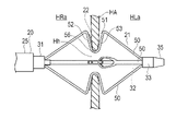
- the medical device is a front view and the living tissue is a cross-sectional view, respectively, schematically showing the state in which the dilated body is arranged in the interatrial septum. It is a figure showing the extended body housed in the storage sheath.
- the medical device is a front view and the biological tissue is a cross-sectional view showing the state in which the dilated body is arranged in the right atrium. It is explanatory drawing which shows the state which expanded the diameter of the dilated body in the interatrial septum from the state of FIG.
- the medical device is a front view and the living tissue is a cross-sectional view, respectively, schematically showing the state in which the dilated body is arranged in the interatrial septum. It is a graph which shows the pattern of the output from an electrode and the time change of an electrode temperature. It is a graph which shows the deformation example of the pattern of the time change of the output from an electrode and the electrode temperature. It is a graph which shows the other variation example of the time change pattern of the output from an electrode and the electrode temperature. It is a front view of the vicinity of the extended body of the 1st modification. It is a front view of the vicinity of the extended body of the 2nd modification. It is a front view of the vicinity of the extended body of the 3rd modification. It is a front view of the vicinity of the extended body of the 4th modification. It is a front view of the vicinity of the extended body of the 5th modification. It is a front view of the vicinity of the extended body of the 6th modification.
- the medical device can perform maintenance measures for expanding the puncture hole Hh formed in the atrial septal HA of the patient's heart H and maintaining the further expanded puncture hole Hh at its size. It is configured as follows.
- the medical device 10 of the present embodiment includes a long shaft portion 20, an expansion body 21 provided at the tip portion of the shaft portion 20, and an energy transfer element for performing maintenance measures. It has a plurality of electrodes 22, a hand operation unit 23 provided at the base end portion of the shaft portion 20, and an energy supply device 100.
- the shaft portion 20 has a tip portion 30 including a base end fixing portion 31 to which the base end of the expansion body 21 is fixed and a tip fixing portion 33 to which the tip end of the expansion body 21 is fixed.
- the tip portion 30 of the shaft portion 20 has a shaft extension portion 32 extending in the extension body 21 from the base end fixing portion 31.
- the shaft portion 20 has a storage sheath 25 provided on the outermost peripheral portion.
- the expansion body 21 can move forward and backward in the axial direction with respect to the storage sheath 25.
- the storage sheath 25 can store the expansion body 21 inside the storage sheath 25 in a state of being moved to the tip end side of the shaft portion 20. By moving the storage sheath 25 from the state in which the expansion body 21 is stored to the base end side, the expansion body 21 can be exposed.
- the shaft portion 20 has a tow shaft 26.
- the tow shaft 26 is provided from the base end of the shaft portion 20 to the shaft extension portion 32, and the tip portion thereof is fixed to the tip member 35.
- the tip member 35 to which the tip of the tow shaft 26 is fixed does not have to be fixed to the expansion body 21. As a result, the tip member 35 can pull the expansion body 21 in the compression direction. Further, when the expansion body 21 is stored in the storage sheath 25, the tip member 35 is separated from the expansion body 21 toward the tip side, so that the expansion body 21 can be easily moved in the extending direction and the storage property can be improved. can.
- the hand operation unit 23 has a housing 40 held by the operator, an operation dial 41 that can be rotated by the operator, and a conversion mechanism 42 that operates in conjunction with the rotation of the operation dial 41.
- the tow shaft 26 is held by the conversion mechanism 42 inside the hand operation unit 23.
- the conversion mechanism 42 can move the tow shaft 26 to be held forward and backward along the axial direction as the operation dial 41 rotates.
- a rack and pinion mechanism can be used as the conversion mechanism 42.
- the expansion body 21 has a plurality of wire rod portions 50 in the circumferential direction.
- four wire rod portions 50 are provided in the circumferential direction.
- Each of the wire rod portions 50 can be expanded and contracted in the radial direction.
- the base end portion of the wire rod portion 50 extends from the base end fixing portion 31 toward the tip end side.
- the tip portion of the wire rod portion 50 extends from the base end portion of the tip fixing portion 33 toward the base end side.
- the wire rod portion 50 is inclined so as to increase in the radial direction from both end portions in the axial direction toward the center portion.
- the wire rod portion 50 has a recess 51 recessed inward in the radial direction of the expansion body 21 in the central portion in the axial direction.
- the innermost portion in the radial direction of the recess 51 is the bottom portion 51a.
- the recess 51 defines a receiving space 51b capable of receiving a living tissue when the expanded body 21 is expanded.
- Each recess 51 has a base end side upright portion 52 extending radially outward from the base end of the bottom portion 51a, and a tip end side upright portion 53 extending radially outward from the tip end of the bottom portion 51a.
- An electrode 22 is arranged in the recess 51 so as to face the receiving space 51b.
- the tip-side upright portion 53 has a slit-shaped central portion in the width direction, and has outer edge portions 55 on both sides and a back support portion 56 at the central portion.
- the wire rod portion 50 forming the expansion body 21 has, for example, a flat plate shape cut out from a cylinder.
- the wire rod forming the expansion body 21 can have a thickness of 50 to 500 ⁇ m and a width of 0.3 to 2.0 mm. However, it may have dimensions outside this range.
- the wire rod portion 50 may have a circular cross-sectional shape or a cross-sectional shape other than that.
- Each of the electrodes 22 arranged in the wire rod portion 50 is arranged in the base end side upright portion 52 so as to face the receiving space 51b.
- the electrode 22 may be arranged not in the proximal end side upright portion 52 but in the distal end side upright portion 53 so as to face the receiving space 51b, or may be arranged in the bottom portion 51a so as to face the receiving space 51b. May be good. Further, a plurality of electrodes 22 may be arranged on each wire rod portion 50.
- the base end side electrode 61 and the tip end side electrode 62 are composed of, for example, bipolar electrodes that receive electrical energy from the energy supply device 100. In this case, electricity is applied between the electrodes 22.
- the electrode 22 and the energy supply device 100 are connected by a conducting wire (not shown) coated with an insulating coating material.
- the conducting wire is led out to the outside via the shaft portion 20 and the hand operation portion 23, and is connected to the energy supply device 100.
- the energy supply device 100 may be arranged in the hand operation unit 23.
- the electrode 22 may also be configured as a monopolar electrode. In this case, electricity is supplied to the counter electrode plate prepared outside the body. Further, instead of the electrode 22, a heat generating element (electrode chip) that receives high frequency electric energy from the energy supply device 100 to generate heat may be used. In this case, electricity is applied between the heat generating elements. Further, the electrode 22 has microwave energy, ultrasonic energy, coherent light such as a laser, a heated fluid, a cooled fluid, one that exerts heating or cooling action by a chemical medium, one that generates frictional heat, and an electric wire. It can be configured by an energy transfer element capable of imparting energy to the puncture hole Hh, such as a heater provided with the above, and the specific form is not particularly limited.
- the wire rod portion 50 can be formed of a metal material.
- the metal material for example, titanium-based (Ti—Ni, Ti—Pd, Ti—Nb—Sn, etc.) alloys, copper-based alloys, stainless steels, ⁇ -titanium steels, and Co—Cr alloys can be used. .. It is better to use an alloy having a spring property such as a nickel-titanium alloy.
- the material of the wire rod portion 50 is not limited to these, and may be formed of other materials.
- the shaft portion 20 is preferably formed of a material having a certain degree of flexibility.
- a material having a certain degree of flexibility examples include polyolefins such as polyethylene, polypropylene, polybutene, ethylene-propylene copolymer, ethylene-vinyl acetate copolymer, ionomer, or a mixture of two or more thereof, and a soft polyvinyl chloride resin.
- fluororesins such as polyamide, polyamide elastomer, polyester, polyester elastomer, polyurethane and polytetrafluoroethylene, polyimide, PEEK, silicone rubber and latex rubber.
- the traction shaft 26 includes, for example, a superelastic alloy such as a nickel-titanium alloy or a copper-zinc alloy, a metal material such as stainless steel, a long wire such as a resin material having a relatively high rigidity, and a polyvinyl chloride or polyethylene. , Polyethylene, or a resin material such as an ethylene-propylene copolymer.
- the tip member 35 is, for example, a polymer material such as polyolefin, polyvinyl chloride, polyamide, polyamide elastomer, polyurethane, polyurethane elastomer, polyimide, fluororesin, or a mixture thereof, or a multilayer tube of two or more kinds of polymer materials. Can be formed.
- a polymer material such as polyolefin, polyvinyl chloride, polyamide, polyamide elastomer, polyurethane, polyurethane elastomer, polyimide, fluororesin, or a mixture thereof, or a multilayer tube of two or more kinds of polymer materials. Can be formed.
- the expansion body 21 housed in the storage sheath 25 is in a state of being contracted in the radial direction.
- the expansion body 21 and the storage sheath 25 move in the axial direction with each other, the expansion body 21 is exposed to the outside of the storage sheath 25 and expands in the radial direction.
- the shaft portion 20 has a bent portion 20a that is previously bent in one direction at a portion on the proximal end side of the extended body 21. This allows the surgeon to easily direct the tip of the shaft 20 to the site where the atrial septum HA is punctured.
- the hand operation unit 23 is provided with a display means so that the operator can grasp the direction of the bent portion 20a inserted into the living body.
- the hand operation unit 23 is provided with an orientation display unit 80 as a display means. A mark indicating the bending direction of the bending portion 20a is displayed on the orientation display portion 80, and the orientation of the shaft portion 20 inserted in the living body can be recognized.
- the hand operation unit 23 has a port 81 for priming the medical device 10.
- the direction in which the port 81 extends from the hand operating portion 23 is set to be the same as the direction in which the bent portion 20a bends. Also with this, since the operator can recognize the direction of the bent portion 20a, the port 81 may be used as the display means.
- the energy supply device 100 has a current supply unit 101 that supplies current to a plurality of electrodes 22, and a control unit 102 that controls the current supply unit 101.
- the control unit 102 is composed of, for example, a CPU (Central Processing Unit), a storage circuit, an operation program, and the like.
- the control unit 102 can control the current supply unit 101 to arbitrarily adjust the supply and stop of the high frequency current from the current supply unit 101.
- the control unit 102 can arbitrarily adjust the output (power) of the high frequency current from the current supply unit 101.
- the current supply unit 101 can supply a current to each of the electrodes 22.
- the current supply unit 101 can start and stop the supply of high-frequency current under the control of the control unit 102.
- the waveform of the high frequency current supplied from the current supply unit 101 is pulse-shaped (rectangular), but the current waveform is not limited to this.
- the frequency of the high frequency current is not particularly limited, but is, for example, 300 k to 115 MHz.
- the current supply unit 101 can repeat the supply time t1 for supplying the high frequency current twice or more. During the repeated supply time t1, a stop time t2 in which the high frequency current is stopped is provided.
- the supply time t1 is preferably 20 seconds or less, more preferably 0.5 to 20 seconds, still more preferably 1 to 15 seconds.
- the period P at which the current supply unit 101 starts supplying the current to the electrode 22 may be constant or may change.
- the stop time t2 may be constant or may change.
- the blood denaturation temperature Tb is about 50 to 60 ° C.
- the treatment method of this embodiment is performed on a patient suffering from heart failure (left heart failure). More specifically, as shown in FIG. 4, for a patient suffering from chronic heart failure in which the blood pressure of the left atrium HLa increases due to the enlargement of the myocardium of the left ventricle of the heart H and the increase in stiffness (hardness). This is the method of treatment performed.
- the treatment method of the present embodiment includes a step (S1) of forming a puncture hole Hh in the atrial septal HA, a step (S2) of arranging the dilator 21 in the puncture hole Hh, and a diameter of the puncture hole Hh by the dilator 21. (S3), a step of confirming hemodynamics in the vicinity of the puncture hole Hh (S4), a step of performing maintenance measures to maintain the size of the puncture hole Hh (S5), and maintenance measures are performed. It has a step (S6) for confirming hemodynamics in the vicinity of the puncture hole Hh after the puncture hole has been performed.
- the surgeon delivers the introducer, which is a combination of a guiding sheath and a dilator, to the vicinity of the atrial septal HA when forming the puncture hole Hh.
- the introducer can be delivered to the right atrium HRa, for example, via the inferior vena cava Iv. Further, the delivery of the introducer can be performed by using the guide wire 11.
- the surgeon can insert the guide wire 11 through the dilator and deliver the introducer along the guide wire 11. It should be noted that the insertion of the introducer into the living body, the insertion of the guide wire 11 and the like can be performed by a known method such as using an introducer for introducing a blood vessel.
- the surgeon penetrates a puncture device (not shown) from the right atrium HRa side toward the left atrium HLa side to form a puncture hole Hh.
- a puncture device for example, a device such as a wire having a sharp tip can be used.
- the puncture device is inserted through a dilator and delivered to the atrial septal HA.
- the puncture device can be delivered to the atrial septal HA in place of the guide wire 11 after removing the guide wire 11 from the dilator.
- the medical device 10 is delivered to the vicinity of the atrial septal HA along the guide wire 11 inserted in advance. At this time, the tip of the medical device 10 penetrates the atrial septum HA and reaches the left atrium HLa, as shown in FIG. Further, when the medical device 10 is inserted, the expansion body 21 is in a state of being housed in the storage sheath 25.
- the expansion body 21 is exposed by moving the storage sheath 25 to the base end side.
- the dilated body 21 is expanded in diameter
- the recess 51 is arranged in the puncture hole Hh of the atrial septum HA
- the receiving space 51b receives the biological tissue surrounding the puncture hole Hh.
- the puncture hole Hh is maintained in the expanded state by the dilator 21.
- the shaft portion 20 of the medical device 10 is appropriately operated by the operator while confirming the orientation of the flexion portion 20a by the display means of the hand operation unit 23, so that the tip side thereof becomes the atrial septum HA in the right atrium HRa. Arranged to face.
- the operator operates the hand operation unit 23 in a state where the atrial septum HA is gripped by the recess 51, moves the traction shaft 26 to the proximal end side, and as shown in FIG. 7, the dilator 21 The living tissue is sandwiched between the recesses 51 of the above.
- the operator delivers the hemodynamic confirmation device 110 to the right atrium HRa via the inferior vena cava Iv.
- the hemodynamic confirmation device 110 for example, a known echo catheter can be used.
- the surgeon can display the echo image acquired by the hemodynamic confirmation device 110 on a display device such as a display, and confirm the blood volume passing through the puncture hole Hh based on the display result.
- the operator performs a maintenance procedure to maintain the size of the puncture hole Hh.
- high-frequency energy is applied to the edge of the puncture hole Hh through the electrode 22, so that the edge of the puncture hole Hh is cauterized (heated and cauterized) by the high-frequency energy.
- the operator operates the energy supply device 100 to start cauterization by each electrode 22.
- the current supply unit 101 is controlled by the control unit 102 to repeatedly supply and stop the high frequency current to the electrode 22 at least twice. During the repeated supply time t1, a stop time t2 in which the high frequency current is stopped is provided.
- the current supply unit 101 repeats the constant supply time t1 twice or more.
- the supply time t1 is 20 seconds or less, and the period P is constant.
- the output E (electric power) from the electrode 22 at each supply time t1 is substantially constant.
- the living tissue to which a high-frequency current is supplied from the electrode 22 raises the temperature due to internal resistance, and the electrode 22 raises the temperature due to the heat transmitted from the living tissue in contact with the living tissue.
- the supply time t1 is 20 seconds or less, it is possible to prevent the temperature T of the electrode 22 or the living tissue in contact with blood from becoming higher than the blood denaturation temperature Tb.
- the temperature T of the electrode 22 and the living tissue in contact with the blood is cooled by the circulating blood. Since the temperature inside the living tissue is not immediately cooled, the effect of cauterization can be maintained satisfactorily.
- the temperature T of the electrode 22 and the living tissue in contact with the blood is suppressed to be equal to or higher than the blood degeneration temperature Tb, and the living body is living. Can sustain ablation of tissue.
- the current supply unit 101 may reduce the output E from the electrode 22 each time the current supply is repeated. Since the heat of the electrode 22 and the living tissue is accumulated every time the current supply is repeated, the temperature T of the electrode 22 and the living tissue tends to be higher than the blood denaturation temperature Tb as the number of repetitions increases. Therefore, by reducing the output E each time the current supply is repeated, it is possible to prevent the temperature T of the electrode 22 or the living tissue in contact with blood from becoming higher than the blood denaturation temperature Tb.
- the stop time t2 which is the cooling time
- the period P also decreases, and the total energy required for cauterization is reduced (output E (electric power)).
- output E electric power
- the current supply unit 101 reduces the output E of the first current supply, and in the final current supply, the output E is increased and the supply time t1 is decreased. You may. By increasing the output E, the living tissue can be strongly cauterized at the end, so that the shape of the formed shunt can be easily maintained in a desired shape. Further, by reducing the supply time t1, it is possible to suppress that the temperature T of the electrode 22 or the living tissue in contact with blood becomes equal to or higher than the blood denaturation temperature Tb due to the final current supply at which the output E becomes maximum.
- the puncture hole Hh When the biological tissue near the edge of the puncture hole Hh is cauterized through the electrode 22, a degenerated portion in which the biological tissue is denatured is formed near the edge. Since the living tissue in the degenerated portion loses its elasticity, the puncture hole Hh can maintain its shape when expanded by the dilator 21.
- the hemodynamics are confirmed again in the step of S6, and when the blood volume passing through the puncture hole Hh is the desired amount, the operator reduces the diameter of the dilated body 21. It is stored in the storage sheath 25, and then removed from the puncture hole Hh. Further, the entire medical device 10 is removed from the living body, and the treatment is completed.
- the operator sandwiches the biological tissue in the recess 51 of the expansion body 21 as shown in FIG. First, cauterization may be performed in the state shown in FIG.
- the medical device 10 is long and has a tip portion 30 including an expansion body 21 that can be expanded and contracted in the radial direction and a base end fixing portion 31 to which the base end of the expansion body 21 is fixed.
- a shaft portion 20, a plurality of electrodes 22 provided along the expansion body 21, and a current supply unit 101 for supplying a current to the electrodes 22 are provided.
- the medical device 10 configured as described above repeatedly supplies and stops the current to the electrode 22, the electrode 22 and the electrode 22 maintain the effect of cauterization while maintaining the total amount of energy output from the electrode 22. It is possible to secure the cooling time of the living tissue in contact with the living tissue and suppress the formation of a thrombus.
- the current supply unit 101 may be controlled so that the output of the electrode 22 decreases each time the current supply is repeated. As a result, it is possible to prevent the temperature of the electrode 22 and the living tissue from becoming higher than the blood denaturation temperature Tb while considering the accumulation of heat each time it is repeated. As the number of repetitions increases and the output from the electrode 22 decreases, the stop time t2 for cooling can be shortened, so that the cauterization time can be shortened.
- the current supply unit 101 may be controlled so that the cycle P for starting the supply of the current to the electrode 22 is shortened each time the current supply is repeated. As a result, the total amount of energy required for cauterization can be supplied in a short time, and the cauterization time can be shortened.
- the current supply unit 101 may be controlled so that the output of the electrode 22 becomes the highest in the final supply of the current supply repeated a plurality of times.
- the living tissue can be strongly cauterized at the end, so that the shape of the formed shunt can be easily maintained in a desired shape.
- the output time t1 for continuing the current supply may be the shortest in the final supply. As a result, it is possible to prevent the temperature of the electrode 22 and the living tissue from becoming higher than the blood denaturation temperature Tb by the final supply in which the output from the electrode 22 is the largest.
- the expansion body 21 has a plurality of wire rod portions 50 that define the recesses 51 so that the recesses 51 have a plurality of recesses 51 arranged at least three at equal intervals in the circumferential direction of the expansion body 21.
- the plurality of recesses 51 each have a bottom portion 51a, a proximal end side upright portion 52, and a tip end side upright portion 53, and the plurality of electrodes 22 may be arranged one by one in the recessed portion 51.
- the recesses 51 are arranged at equal intervals in the circumferential direction of the expansion body 21, so that when the tissue around the puncture hole Hh formed in the living body is cauterized, the shape can be made close to a regular polygon. , Can form a shunt of the size targeted by the surgeon.
- the current supply unit 101 may be controlled so that the current supply to the electrode 22 is 20 seconds or less each time. As a result, it is possible to prevent the temperature of the electrode 22 and the living tissue from becoming higher than the blood denaturation temperature Tb.
- the expansion body 21 that can be expanded and contracted in the radial direction including the recess 51 recessed inward in the radial direction and the base end fixing portion 31 in which the base end of the expansion body 21 is fixed are fixed.
- a long shaft portion 20 having a tip portion 30 including the above, a plurality of electrodes 22 provided along a part of a recess 51 of the expansion body 21, and a current supply portion 101 for supplying a current to the electrodes 22. It is a control method of the medical device 10, and controls the current supply unit 101 so as to repeat the supply and stop of the current supplied from the current supply unit 101 to the electrode 22 at least twice.
- the current is not supplied to the electrode 22 that is not in contact with the biological tissue of each electrode 22, but the current is supplied only to the electrode 22 that is in contact with the biological tissue, so that a thrombus is formed. It can be suppressed and effectively cauterized.
- the present invention is not limited to the above-described embodiment, and various modifications can be made by those skilled in the art within the technical idea of the present invention.
- the current supply between the electrodes 22a and 22c is performed when the currents of the electrodes 22b and 22d are stopped. Therefore, the current supply of the electrode 22b and the electrode 22d is performed when the current of the electrode 22a and the electrode 22c is stopped.
- the number of electrodes 22 and the timing of repeating the supply and stop of the high frequency current are not limited.
- At least one of the plurality of electrodes 22a, 22b, 22c, and 22d may be supplied with a current at a timing different from that of the other electrodes. As a result, it is possible to prevent the temperature of the electrode 22 and the living tissue from becoming higher than the blood denaturation temperature Tb because the timing of heating by the electrode 22 is different.
- the expansion body 21 may have a structure in which a portion on the tip end side of the recess 51 is not provided.
- the adjacent wire rod portions 50 are not connected in the example of FIG. 13, they may be connected to each other.
- the expansion body 21 may be a balloon that can be expanded by supplying a fluid to the inside.
- the balloon is shaped to form a recess 51 when expanded.
- the expansion body 21 may be formed of a mesh in which a large number of thin wires are knitted.
- the mesh is shaped to form a recess 51 when expanded.
- the expansion body 21 may be formed by a link structure connected by a joint 57.
- the extended body 21 may be formed in a mesh shape in which the wire rod portions are branched and merged.
- the expansion body 21 has a plurality of recesses 51, and the electrode 22 is arranged in the base end side upright portion 52 of each recess 51.
- the traction shaft is not provided. Therefore, the expansion body 21 released from the storage sheath 25 expands the puncture hole Hh only by its own expansion force.
- control unit 102 receives temperature data from a temperature sensor (not shown) arranged in the vicinity of the electrode 22, and supplies time t1 so that the temperature of the electrode 22 or the living tissue does not exceed the blood denaturation temperature Tb. At least one of the stop time t2, the output E, the period P, or the number of repetitions may be feedback-controlled.
Landscapes
- Health & Medical Sciences (AREA)
- Surgery (AREA)
- Life Sciences & Earth Sciences (AREA)
- Engineering & Computer Science (AREA)
- Heart & Thoracic Surgery (AREA)
- General Health & Medical Sciences (AREA)
- Veterinary Medicine (AREA)
- Public Health (AREA)
- Nuclear Medicine, Radiotherapy & Molecular Imaging (AREA)
- Biomedical Technology (AREA)
- Animal Behavior & Ethology (AREA)
- Medical Informatics (AREA)
- Molecular Biology (AREA)
- Dentistry (AREA)
- Mechanical Engineering (AREA)
- Cardiology (AREA)
- Physics & Mathematics (AREA)
- Plasma & Fusion (AREA)
- Otolaryngology (AREA)
- Surgical Instruments (AREA)
Priority Applications (4)
| Application Number | Priority Date | Filing Date | Title |
|---|---|---|---|
| EP21875482.8A EP4212116A4 (en) | 2020-09-29 | 2021-09-27 | MEDICAL DEVICE AND METHOD FOR CONTROLLING SAME |
| JP2022553929A JPWO2022071180A1 (cg-RX-API-DMAC7.html) | 2020-09-29 | 2021-09-27 | |
| CN202180063180.6A CN116322545A (zh) | 2020-09-29 | 2021-09-27 | 医疗设备及其控制方法 |
| US18/192,028 US20230233225A1 (en) | 2020-09-29 | 2023-03-29 | Medical device and method of controlling same |
Applications Claiming Priority (2)
| Application Number | Priority Date | Filing Date | Title |
|---|---|---|---|
| JP2020-163592 | 2020-09-29 | ||
| JP2020163592 | 2020-09-29 |
Related Child Applications (1)
| Application Number | Title | Priority Date | Filing Date |
|---|---|---|---|
| US18/192,028 Continuation US20230233225A1 (en) | 2020-09-29 | 2023-03-29 | Medical device and method of controlling same |
Publications (1)
| Publication Number | Publication Date |
|---|---|
| WO2022071180A1 true WO2022071180A1 (ja) | 2022-04-07 |
Family
ID=80951573
Family Applications (1)
| Application Number | Title | Priority Date | Filing Date |
|---|---|---|---|
| PCT/JP2021/035258 Ceased WO2022071180A1 (ja) | 2020-09-29 | 2021-09-27 | 医療デバイスおよびその制御方法 |
Country Status (5)
| Country | Link |
|---|---|
| US (1) | US20230233225A1 (cg-RX-API-DMAC7.html) |
| EP (1) | EP4212116A4 (cg-RX-API-DMAC7.html) |
| JP (1) | JPWO2022071180A1 (cg-RX-API-DMAC7.html) |
| CN (1) | CN116322545A (cg-RX-API-DMAC7.html) |
| WO (1) | WO2022071180A1 (cg-RX-API-DMAC7.html) |
Citations (3)
| Publication number | Priority date | Publication date | Assignee | Title |
|---|---|---|---|---|
| JP2010068866A (ja) | 2008-09-16 | 2010-04-02 | Nippon Erekuteru:Kk | 高周波加温バルーンカテーテル |
| WO2019009254A1 (ja) * | 2017-07-04 | 2019-01-10 | テルモ株式会社 | 医療デバイス、および処置方法 |
| JP2020163592A (ja) | 2019-03-28 | 2020-10-08 | ブラザー工業株式会社 | 画像記録装置 |
Family Cites Families (6)
| Publication number | Priority date | Publication date | Assignee | Title |
|---|---|---|---|---|
| EP0957792A4 (en) * | 1995-05-02 | 2000-09-20 | Heart Rhythm Tech Inc | ARRANGEMENT FOR CONTROLLING AN ABLATION ENERGY SUPPLIED TO A PATIENT |
| US20070179482A1 (en) * | 2004-05-07 | 2007-08-02 | Anderson Robert S | Apparatuses and methods to treat biological external tissue |
| US10111703B2 (en) * | 2014-05-06 | 2018-10-30 | Cosman Instruments, Llc | Electrosurgical generator |
| WO2019109013A1 (en) * | 2017-11-30 | 2019-06-06 | Alleviant Medical, Inc. | Transcatheter device for interatrial anastomosis |
| JP2019150316A (ja) * | 2018-03-02 | 2019-09-12 | テルモ株式会社 | 医療器具 |
| WO2019189079A1 (ja) * | 2018-03-29 | 2019-10-03 | テルモ株式会社 | 医療デバイス |
-
2021
- 2021-09-27 WO PCT/JP2021/035258 patent/WO2022071180A1/ja not_active Ceased
- 2021-09-27 EP EP21875482.8A patent/EP4212116A4/en active Pending
- 2021-09-27 JP JP2022553929A patent/JPWO2022071180A1/ja active Pending
- 2021-09-27 CN CN202180063180.6A patent/CN116322545A/zh active Pending
-
2023
- 2023-03-29 US US18/192,028 patent/US20230233225A1/en not_active Abandoned
Patent Citations (3)
| Publication number | Priority date | Publication date | Assignee | Title |
|---|---|---|---|---|
| JP2010068866A (ja) | 2008-09-16 | 2010-04-02 | Nippon Erekuteru:Kk | 高周波加温バルーンカテーテル |
| WO2019009254A1 (ja) * | 2017-07-04 | 2019-01-10 | テルモ株式会社 | 医療デバイス、および処置方法 |
| JP2020163592A (ja) | 2019-03-28 | 2020-10-08 | ブラザー工業株式会社 | 画像記録装置 |
Non-Patent Citations (1)
| Title |
|---|
| See also references of EP4212116A4 |
Also Published As
| Publication number | Publication date |
|---|---|
| JPWO2022071180A1 (cg-RX-API-DMAC7.html) | 2022-04-07 |
| EP4212116A1 (en) | 2023-07-19 |
| CN116322545A (zh) | 2023-06-23 |
| US20230233225A1 (en) | 2023-07-27 |
| EP4212116A4 (en) | 2024-02-14 |
Similar Documents
| Publication | Publication Date | Title |
|---|---|---|
| JP7538283B2 (ja) | 医療デバイス | |
| JP7021211B2 (ja) | 医療デバイス | |
| US11950836B2 (en) | Medical device and treatment method | |
| JP7270605B2 (ja) | 医療デバイス | |
| JP7543293B2 (ja) | 医療デバイス | |
| JP7513624B2 (ja) | 医療デバイス | |
| WO2022071179A1 (ja) | 医療デバイスおよびシャント形成方法 | |
| WO2021065874A1 (ja) | 医療デバイス | |
| WO2022071168A1 (ja) | 医療デバイスおよびシャント形成方法 | |
| WO2021065912A1 (ja) | 医療デバイス | |
| JP7797477B2 (ja) | 医療デバイス | |
| WO2022071169A1 (ja) | 医療デバイスシステムおよび電極部接触検出方法 | |
| JP7756090B2 (ja) | 医療デバイス | |
| US20230233225A1 (en) | Medical device and method of controlling same | |
| JP2022136661A (ja) | 医療デバイス | |
| JP2022038122A (ja) | 医療デバイスおよびシャント形成方法 | |
| JP2022038121A (ja) | 医療デバイスおよびシャント形成方法 | |
| WO2022071170A1 (ja) | 医療デバイスおよびシャント形成方法 |
Legal Events
| Date | Code | Title | Description |
|---|---|---|---|
| 121 | Ep: the epo has been informed by wipo that ep was designated in this application |
Ref document number: 21875482 Country of ref document: EP Kind code of ref document: A1 |
|
| ENP | Entry into the national phase |
Ref document number: 2022553929 Country of ref document: JP Kind code of ref document: A |
|
| WWE | Wipo information: entry into national phase |
Ref document number: 2021875482 Country of ref document: EP |
|
| ENP | Entry into the national phase |
Ref document number: 2021875482 Country of ref document: EP Effective date: 20230413 |
|
| NENP | Non-entry into the national phase |
Ref country code: DE |