WO2022070808A1 - 災害情報処理装置、災害情報処理装置の作動方法、災害情報処理装置の作動プログラム、並びに災害情報処理システム - Google Patents
災害情報処理装置、災害情報処理装置の作動方法、災害情報処理装置の作動プログラム、並びに災害情報処理システム Download PDFInfo
- Publication number
- WO2022070808A1 WO2022070808A1 PCT/JP2021/032903 JP2021032903W WO2022070808A1 WO 2022070808 A1 WO2022070808 A1 WO 2022070808A1 JP 2021032903 W JP2021032903 W JP 2021032903W WO 2022070808 A1 WO2022070808 A1 WO 2022070808A1
- Authority
- WO
- WIPO (PCT)
- Prior art keywords
- drone
- shooting range
- damage situation
- disaster
- information processing
- Prior art date
- Legal status (The legal status is an assumption and is not a legal conclusion. Google has not performed a legal analysis and makes no representation as to the accuracy of the status listed.)
- Ceased
Links
Images


Classifications
-
- H—ELECTRICITY
- H04—ELECTRIC COMMUNICATION TECHNIQUE
- H04N—PICTORIAL COMMUNICATION, e.g. TELEVISION
- H04N7/00—Television systems
- H04N7/18—Closed-circuit television [CCTV] systems, i.e. systems in which the video signal is not broadcast
- H04N7/181—Closed-circuit television [CCTV] systems, i.e. systems in which the video signal is not broadcast for receiving images from a plurality of remote sources
-
- G—PHYSICS
- G06—COMPUTING OR CALCULATING; COUNTING
- G06V—IMAGE OR VIDEO RECOGNITION OR UNDERSTANDING
- G06V20/00—Scenes; Scene-specific elements
- G06V20/10—Terrestrial scenes
- G06V20/17—Terrestrial scenes taken from planes or by drones
-
- G—PHYSICS
- G06—COMPUTING OR CALCULATING; COUNTING
- G06V—IMAGE OR VIDEO RECOGNITION OR UNDERSTANDING
- G06V20/00—Scenes; Scene-specific elements
- G06V20/10—Terrestrial scenes
- G06V20/176—Urban or other man-made structures
-
- G—PHYSICS
- G08—SIGNALLING
- G08B—SIGNALLING SYSTEMS, e.g. PERSONAL CALLING SYSTEMS; ORDER TELEGRAPHS; ALARM SYSTEMS
- G08B25/00—Alarm systems in which the location of the alarm condition is signalled to a central station, e.g. fire or police telegraphic systems
-
- H—ELECTRICITY
- H04—ELECTRIC COMMUNICATION TECHNIQUE
- H04N—PICTORIAL COMMUNICATION, e.g. TELEVISION
- H04N23/00—Cameras or camera modules comprising electronic image sensors; Control thereof
- H04N23/60—Control of cameras or camera modules
- H04N23/61—Control of cameras or camera modules based on recognised objects
-
- H—ELECTRICITY
- H04—ELECTRIC COMMUNICATION TECHNIQUE
- H04N—PICTORIAL COMMUNICATION, e.g. TELEVISION
- H04N23/00—Cameras or camera modules comprising electronic image sensors; Control thereof
- H04N23/60—Control of cameras or camera modules
- H04N23/69—Control of means for changing angle of the field of view, e.g. optical zoom objectives or electronic zooming
-
- H—ELECTRICITY
- H04—ELECTRIC COMMUNICATION TECHNIQUE
- H04N—PICTORIAL COMMUNICATION, e.g. TELEVISION
- H04N23/00—Cameras or camera modules comprising electronic image sensors; Control thereof
- H04N23/90—Arrangement of cameras or camera modules, e.g. multiple cameras in TV studios or sports stadiums
Definitions
- the technology of the present disclosure relates to a disaster information processing device, an operation method of the disaster information processing device, an operation program of the disaster information processing device, and a disaster information processing system.
- Patent Document 1 describes disaster information in which a drone is directed to a disaster site, a camera mounted on the drone is used to take a picture of the disaster site, and an aerial image obtained by the drone is used to grasp the damage situation of the disaster site.
- the processing equipment is described.
- the disaster site is, for example, a main building in a disaster area where a fire is occurring, a main building in a disaster area inundated by a flood, and the like.
- Patent Document 1 the discussion is proceeding on the premise that the disaster site is known to some extent. However, immediately after the disaster, although the disaster area including the disaster site can be known, it is clear where the disaster site is due to the disaster-specific confusion such as the destruction of the information transmission infrastructure such as mobile phone base stations. In many cases, it does not.
- One embodiment according to the technique of the present disclosure includes a disaster information processing apparatus capable of grasping the damage situation at a disaster site in a short time without waste, an operation method of the disaster information processing apparatus, an operation program of the disaster information processing apparatus, and the like. It also provides a disaster information processing system.
- the disaster information processing apparatus of the present disclosure includes a processor and a memory connected to or built in the processor, and the processor uses a first camera mounted on the first drone to cover a first shooting range including a disaster area.
- the first aerial image obtained by shooting is accepted, the first damage situation of the disaster in the first shooting range is analyzed based on the first aerial image, and the first is based on the analysis result of the first damage situation. 2
- the second shooting range of the second camera mounted on the drone which is relatively narrower than the first shooting range, is determined.
- the processor determines the shooting range including the area where the damage is relatively large by the analysis of the first damage situation in the disaster area as the second shooting range.
- the processor receives the second aerial image obtained by photographing the second shooting range with the second camera, and analyzes the second damage situation of the disaster in the second shooting range based on the second aerial image. Is preferable.
- the processor analyzes the second damage situation based on the first aerial image in addition to the second aerial image.
- the processor sets the flight altitude of the second drone lower than that of the first drone.
- the processor analyzes the first damage situation for each section including a plurality of adjacent buildings.
- the flight range of the second drone is preset, and the processor determines that the damage to the area within the flight range of the target second drone is relatively small by the analysis of the first damage situation, and the target If there is an area where the damage is relatively large in a flight range different from the flight range of the second drone, the shooting range including the area where the damage is relatively large is taken as the target second drone. It is preferable to determine it as the second shooting range.
- the processor determines the second shooting range for each of the plurality of second drones.
- the method of operating the disaster information processing apparatus of the present disclosure is to receive the first aerial image obtained by photographing the first photographing range including the disaster area by the first camera mounted on the first drone. Analyzing the first damage situation of the disaster in the first shooting range based on the 1 aerial image, and the second of the second camera mounted on the second drone based on the analysis result of the first damage situation. It includes determining a second shooting range which is a shooting range and is relatively narrower than the first shooting range.
- the operation program of the disaster information processing apparatus of the present disclosure accepts the first aerial image obtained by photographing the first photographing range including the disaster area by the first camera mounted on the first drone. Analyzing the first damage situation of the disaster in the first shooting range based on the 1 aerial image, and the second camera of the second camera mounted on the second drone based on the analysis result of the first damage situation.
- the computer is made to execute a process including determining a second shooting range which is a shooting range and is relatively narrower than the first shooting range.
- the disaster information processing system of the present disclosure is relative to the first drone equipped with the first camera that shoots the first shooting range including the disaster area and outputs the first aerial shot image, and the first shooting range.
- the processor comprises a second drone equipped with a second camera that captures a narrow second shooting range and outputs a second aerial image, a processor, and a memory connected to or built into the processor.
- the first aerial image is accepted, the first damage situation of the disaster in the first shooting range is analyzed based on the first aerial image, and the second shooting range is determined based on the analysis result of the first damage situation. ..
- a disaster information processing device that can grasp the damage situation at a disaster site in a short time without waste, an operation method of the disaster information processing device, an operation program of the disaster information processing device, and disaster information processing.
- the system can be provided.
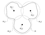
- the disaster information processing system 2 for grasping the damage situation of a disaster includes the first drones 10_1, 10_2, and 10_3, the second drones 11A_1, 11B_1, 11A_2, 11B_2, 11A_3, and It includes 11B_3 and a disaster information processing server 12.
- the first drones 10_1, 10_2, and 10_3 and the second drones 11A_1, 11B_1, 11A_2, 11B_2, 11A_3, and 11B_3 are the same model and have the same performance.
- the first drones 10_1, 10_2, and 10_3 are collectively referred to as the first drone 10.
- the second drones 11A_1, 11B_1, 11A_2, 11B_2, 11A_3, and 11B_3 are collectively referred to as the second drone 11.
- Codes having other underbars FR_1, FR_2, and FR_3, FB_1, FB_2, and FB_3, 80_N, 80_E, 80_S, 80_W, etc. may also be omitted after the underscore.
- the first drone 10_1 and the second drones 11A_1 and 11B_1 are in charge of the first flight range FR_1.
- the first drone 10_2 and the second drones 11A_2 and 11B_2 are in charge of the second flight range FR_2.
- the first drone 10_3 and the second drones 11A_3 and 11B_3 are in charge of the third flight range FR_3.
- the flight range FR is preset in the first drone 10 and the second drone 11.
- the first drone 10, the second drone 11, and the disaster information processing server 12 are connected to each other so as to be able to communicate with each other via the network 13.
- the first drone 10 and the second drone 11 are wirelessly connected to the network 13.
- the disaster information processing server 12 is connected to the network 13 by wire or wirelessly.
- the network 13 is a WAN (Wide Area Network) of, for example, the Internet or a public communication network.
- WAN Wide Area Network
- VPN Virtual Private Network
- HTTPS Hypertext Transfer Protocol
- the disaster information processing server 12 is installed at the disaster countermeasures headquarters (agency, government office, etc.) of local governments such as prefectures and municipalities.
- the disaster information processing server 12 is an example of the "disaster information processing apparatus" according to the technique of the present disclosure.
- the client terminal 14 is also connected to the network 13 by wire or wirelessly.
- the client terminal 14 is, for example, a desktop personal computer deployed to the staff of the disaster response headquarters, and has a display 15 and an input device 16. Various screens are displayed on the display 15.
- the input device 16 is a keyboard, a mouse, a touch panel, a microphone, or the like. Although only one client terminal 14 is drawn in FIG. 1, of course, there may be a plurality of client terminals 14.
- the flight range FR is, for example, a circle with a radius of 5 km to 10 km, and is preset to cover the entire area 20. There is.
- the flight range FR may partially overlap as shown in the figure.
- the flight range FR has a departure / arrival base FB for the first drone 10 and the second drone 11 at the center thereof. More specifically, the first flight range FR_1 has a first departure / arrival base FB_1, the second flight range FR_2 has a second departure / arrival base FB_2, and the third flight range FR_3 has a third departure / arrival base FB_3.
- the area 20 is an area where a disaster countermeasures headquarters is located due to a disaster, and is an example of a “disaster area” related to the technology of the present disclosure.
- the first drone 10 takes off from the departure / arrival base FB prior to the second drone 11, and takes a first aerial image 25 from a flight altitude of, for example, 500 m. After taking the first aerial image 25, the first drone 10 returns to the departure / arrival base FB.
- the second drone 11 takes off from the departure / arrival base FB after the first drone 10, and takes a second aerial image 26 from a flight altitude of, for example, 100 m. After taking the second aerial image 26, the second drone 11 returns to the departure / arrival base FB.
- the first drone 10 and the second drone 11 take the first aerial image 25 and the second aerial image 26 by setting the zoom magnification to the same value, for example, the same magnification. Therefore, in the first aerial image 25, a relatively large number of buildings appear relatively small. On the other hand, in the second aerial image 26, a relatively small number of buildings are shown in a relatively large size.
- the first drone 10 or the second drone 11 includes an airframe 30, an arm 31, a propeller 32, a motor 33, a skid 34, a gimbal 35, a first camera 36, a second camera 37, and the like.
- the first camera 36 is mounted on the first drone 10
- the second camera 37 is mounted on the second drone 11.
- the propeller 32 is also called a blade or a rotary blade.
- the motor 33 is also called a rotor.
- the arm 31 is four rod-shaped bodies extending from the machine body 30 in four directions symmetrical in the lateral direction.
- a total of four propellers 32 are provided, one at the tip of the arm 31.
- a motor 33 is attached to the propeller 32. The motor 33 rotates the propeller 32 to fly the first drone 10 or the second drone 11. Further, the motor 33 changes the flight direction of the first drone 10 or the second drone 11 by changing its rotation direction and rotation speed.
- the skid 34 is four rod-shaped bodies extending from the machine body 30 in four directions symmetrical downward.
- the skid 34 is provided to stably land the first drone 10 or the second drone 11 on the ground.
- the gimbal 35 holds the first camera 36 or the second camera 37 in a tiltable manner under the machine body 30.
- the gimbal 35 reduces the shaking generated in the airframe 30 during flight so as not to be transmitted to the first camera 36 or the second camera 37.
- the first drone 10 or the second drone 11 has a storage 40, a memory 41, a CPU (Central Processing Unit) 42, a communication unit 43, a power supply unit 44, and the like.
- a storage 40 a memory 41
- a CPU (Central Processing Unit) 42 a CPU (Central Processing Unit) 42
- a communication unit 43 a communication unit 43
- a power supply unit 44 a power supply unit 44
- the memory 41 is a work memory for the CPU 42 to execute a process.
- the CPU 42 loads the operation program 45 stored in the storage 40 into the memory 41, and executes the process according to the operation program 45. As a result, the CPU 42 comprehensively controls the operation of each part of the first drone 10 or the second drone 11.
- the communication unit 43 is responsible for wireless communication with the disaster information processing server 12 and the pilot 50.
- the pilot 50 is operated by the operator of the first drone 10 or the second drone 11.
- the first drone 10 or the second drone 11 is basically an autonomous flight, but can be manually operated by the pilot 50 in order to respond to an emergency.
- the pilot 50 is also referred to as a proportional system, abbreviated as a radio.
- a rechargeable battery 53 such as a secondary battery is connected to the power feeding unit 44.
- the power feeding unit 44 supplies electric power from the battery 53 to each unit.
- a GPS (Global Positioning System) module 55 a gyro sensor 56, an acceleration sensor 57, an azimuth sensor 58, an altitude sensor 59, and the like are connected to the CPU 42.
- the GPS module 55 receives a signal from a GPS satellite and identifies the latitude and longitude of the position of the first drone 10 or the second drone 11 based on the received signal.
- the GPS module 55 outputs the specified latitude and longitude to the CPU 42.
- the gyro sensor 56 detects the tilt angle representing the posture of the first drone 10 or the second drone 11.
- the gyro sensor 56 outputs the detected tilt angle to the CPU 42.
- the acceleration sensor 57 detects the acceleration of the first drone 10 or the second drone 11.
- the acceleration sensor 57 outputs the detected acceleration to the CPU 42.
- the speed of the first drone 10 or the second drone 11 may be calculated by integrating the acceleration detected by the acceleration sensor 57.
- the azimuth sensor 58 detects an angle representing the direction in which the front of the first drone 10 or the second drone 11 is facing, that is, the azimuth angle based on the geomagnetism.
- the azimuth sensor 58 outputs the detected azimuth to the CPU 42.
- the front surface of the first drone 10 or the second drone 11 is the side on which the lens optical axis of the first camera 36 or the second camera 37 faces.
- the altitude sensor 59 detects the flight altitude of the first drone 10 or the second drone 11.
- the altitude sensor 59 is, for example, a sensor that measures atmospheric pressure and converts it into flight altitude.
- the altitude sensor 59 may be a sensor that irradiates the ground surface with infrared laser light, receives the reflected light, and measures the distance from the ground surface based on the received reflected light.
- the altitude sensor 59 may be an ultrasonic sensor that irradiates the ground surface with ultrasonic waves, receives the echo, and measures the distance from the ground surface based on the received echo.
- the altitude sensor 59 outputs the detected flight altitude to the CPU 42.
- the CPU 42 functions as the flight controller 65 and the camera controller 66.
- the flight controller 65 controls the operation of the motor 33 via the motor driver 67.
- the camera controller 66 controls the operation of the first camera 36 or the second camera 37, causes the first camera 36 to shoot the first aerial image 25, and causes the second camera 37 to shoot the second aerial image 26. Further, the camera controller 66 receives the first aerial image 25 or the second aerial image 26 from the first camera 36 or the second camera 37, and performs image processing on the first aerial image 25 or the second aerial image 26. After that, the first aerial image 25 or the second aerial image 26 is transmitted to the disaster information processing server 12 via the communication unit 43.
- the storage 40 stores the first shooting range information 70 or the second shooting range information 71. More specifically, the storage 40 of the first drone 10 stores the first shooting range information 70, and the storage 40 of the second drone 11 stores the second shooting range information 71.
- the first shooting range information 70 is stored in the storage 40 of the first drone 10 in advance before the disaster.
- the second shooting range information 71 is transmitted from the disaster information processing server 12 to the second drone 11 after the disaster, and is stored in the storage 40 of the second drone 11.
- the flight controller 65 refers to the first shooting range information 70 or the second shooting range information 71 while referring to various input data from the GPS module 55, the gyro sensor 56, the acceleration sensor 57, the orientation sensor 58, the altitude sensor 59, and the like. Control according to the situation.
- the first shooting range information 70 is information regarding the first shooting range 80 (see FIG. 7), which is the shooting range of the first aerial image 25 of the first camera 36.
- the first imaging range information 70 has items of latitude and longitude, direction, and altitude.
- the latitude and longitude above the departure and arrival base FB are registered in the latitude and longitude item.
- four azimuth angles of 0 ° (north), 90 ° (east), 180 ° (south), and 270 ° (west) are registered in the azimuth item.
- 500 m shown in FIG. 3 is registered in the altitude item.
- the first shooting range 80 defined by the first shooting range information 70 has a rectangular shape, and has four first shooting ranges 80_N, 80_E, 80_S, and 80_W. These first shooting ranges 80_N, 80_E, 80_S, and 80_W cover the entire flight range FR.
- the first shooting range 80_N is a shooting range when the azimuth angle of the first drone 10 is 0 °.
- the first shooting range 80_E is the shooting range when the azimuth angle of the first drone 10 is 90 °
- the first shooting range 80_S is the shooting range when the azimuth angle of the first drone 10 is 180 °.
- the first shooting range 80_W is a shooting range when the azimuth angle of the first drone 10 is 270 °. Further, these first shooting ranges 80_N, 80_E, 80_S, and 80_W are all shooting ranges when the departure / arrival base FB is viewed directly below by the first camera 36.
- the flight controller 65 of the first drone 10 first flies the first drone 10 to a position 500 m above the departure / arrival base FB according to the first shooting range information 70. Then, while hovering the first drone 10 at a position 500 m above the departure / arrival base FB, the azimuths are sequentially changed to 0 °, 90 °, 180 °, and 270 °.
- the camera controller 66 of the first drone 10 captures the first shooting ranges 80_N, 80_E, 80_S, and 80_W at the respective azimuth angles of 0 °, 90 °, 180 °, and 270 °, for a total of four images.
- the first aerial image 25 is photographed.
- the first shooting range 80 a range in which the damage status of the building reflected in the first aerial image 25 can be analyzed is set.
- the first shooting range 80 varies depending on the flight altitude of the first drone 10, the resolution of the first camera 36, the angle of view of the first camera 36, and the like. Therefore, as in the example of FIG. 7, the entire flight range FR may be covered by a plurality of first shooting ranges 80, or the entire flight range FR may be covered by one first shooting range 80. be.
- the computer constituting the disaster information processing server 12 includes a storage 85, a memory 86, a CPU (Central Processing Unit) 87, and a communication unit 88. These are interconnected via a bus line 89.
- the CPU 87 is an example of a "processor" according to the technique of the present disclosure.
- the storage 85 is a hard disk drive built in the computer constituting the disaster information processing server 12 or connected via a cable or a network 13. Alternatively, the storage 85 is a disk array in which a plurality of hard disk drives are connected.
- the storage 85 stores control programs such as an operating system, various application programs, and various data associated with these programs.
- a solid state drive may be used instead of the hard disk drive.
- the memory 86 is a work memory for the CPU 87 to execute a process.
- the CPU 87 loads the program stored in the storage 85 into the memory 86, and executes the process according to the program. As a result, the CPU 87 comprehensively controls the operation of each part of the computer.
- the communication unit 88 controls transmission of various information with external devices such as the first drone 10 and the second drone 11.
- the memory 86 may be built in the CPU 87.
- the operation program 95 is stored in the storage 85 of the disaster information processing server 12.
- the operation program 95 is an application program for making the computer function as the disaster information processing server 12. That is, the operation program 95 is an example of the "operation program of the disaster information processing apparatus" according to the technique of the present disclosure.
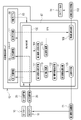
- the CPU 87 of the computer constituting the disaster information processing server 12 cooperates with the memory 86 and the like to read / write (hereinafter abbreviated as RW (Read Write)) control unit 100, first. It functions as a damage status analysis unit 101, a second shooting range determination unit 102, a transmission control unit 103, a second damage status analysis unit 104, and a screen distribution control unit 105.
- RW Read Write
- the RW control unit 100 controls the storage of various data in the storage 85 and the reading of various data in the storage 85. For example, the RW control unit 100 receives the first aerial image 25 from the first drone 10 and stores the accepted first aerial image 25 in the storage 85. Further, the RW control unit 100 receives the second aerial image 26 from the second drone 11 and stores the received second aerial image 26 in the storage 85.
- the RW control unit 100 reads the first aerial image 25 from the storage 85, and outputs the read first aerial image 25 to the first damage situation analysis unit 101. Further, the RW control unit 100 reads the second aerial image 26 from the storage 85, and outputs the read second aerial image 26 to the second damage situation analysis unit 104.
- the first damage situation analysis unit 101 analyzes the first damage situation 127 (see FIG. 10) of the disaster in the first shooting range 80 based on the first aerial image 25.
- the first damage situation analysis unit 101 outputs the analysis result (hereinafter, abbreviated as the first analysis result) 110 of the first damage situation 127 to the second shooting range determination unit 102.
- the second shooting range determination unit 102 determines the second shooting range 136 (see FIG. 13) of the second camera 37 of the second drone 11 based on the first analysis result 110.
- the second shooting range determination unit 102 outputs the second shooting range information 71, which is the information of the determined second shooting range 136, to the transmission control unit 103.
- the transmission control unit 103 controls to transmit the second shooting range information 71 to the second drone 11.
- the second damage situation analysis unit 104 analyzes the second damage situation 148 (see FIG. 14) of the disaster in the second shooting range 136 based on the second aerial image 26.
- the second damage situation analysis unit 104 outputs the analysis result (hereinafter, abbreviated as the second analysis result) 111 of the second damage situation 148 to the RW control unit 100.
- the RW control unit 100 stores the second analysis result 111 in the storage 85.
- the RW control unit 100 When a distribution request (not shown) from the client terminal 14 is received, the RW control unit 100 reads the second analysis result 111 from the storage 85 and outputs the read second analysis result 111 to the screen distribution control unit 105.
- the screen distribution control unit 105 generates a damage status display screen 112 based on the second analysis result 111.
- the screen distribution control unit 105 controls distribution of the screen data of the generated damage status display screen 112 to the client terminal 14 that is the request source of the distribution request.
- the screen data is screen data for web distribution created by a markup language such as XML (XML (Extensible Markup Language)).
- the client terminal 14 reproduces and displays the damage status display screen 112 on the web browser based on the screen data.
- JSON Javascript (registered trademark) Object Notification
- the first damage situation analysis unit 101 has a section image cutting unit 120 and a first processing unit 121.
- the section image cutting section 120 cuts out the section image 123 for each section 135 (see FIG. 13) from the first aerial image 25 with reference to the landmark building information 122.
- Section 135 is a plurality of areas obtained by dividing the area 20 and includes a plurality of adjacent buildings.
- the section 135 is a chome such as "Fuji 1-chome" or "Watabuki Kitsuneana 2-chome".
- the section image cutting unit 120 outputs a section image group 125 including a plurality of sets of the section image 123 and the section information 124 representing the section 135 of the section image 123 to the first processing unit 121.
- the landmark building information 122 is stored in the storage 85, is read from the storage 85 by the RW control unit 100, and is output to the section image cutting unit 120.
- the landmark building information 122 includes an aerial image of a landmark building that is a building located at a corner of each section 135, and section information 124 of the section 135 to which the landmark building belongs.
- the section image cutting unit 120 finds the landmark building from the first aerial image 25 by using a well-known image recognition technique and relying on the aerial image of the landmark building. Then, the area surrounded by the line connecting the found landmark buildings is cut out from the first aerial image 25 as the section image 123.
- the first processing unit 121 inputs the section image 123 into the first damage situation analysis model 126. Then, the first damage situation 127 is output from the first damage situation analysis model 126. The first damage situation 127 is either "large damage” or "small damage”. The first processing unit 121 outputs the first damage situation 127 from the first damage situation analysis model 126 for all the section images 123 included in the section image group 125. The first processing unit 121 outputs the first analysis result 110 that summarizes the first damage situation 127 for each section 135.
- FIG. 10 illustrates a case where the first damage situation 127 of the section 135 such as “Fuji 1-chome” and “Cotton fox hole 2-chome” is “damaged”.
- the first damage situation analysis model 126 is a machine learning model constructed by methods such as a neural network, a support vector machine, and boosting.
- the first damage situation analysis model 126 is stored in the storage 85, is read from the storage 85 by the RW control unit 100, and is output to the first processing unit 121.
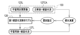
- the first damage situation analysis model 126 is given the learning data 130 and is trained.
- the learning data 130 is a set of the learning section image 123L and the correct answer first damage situation 127CA corresponding to the learning section image 123L.
- the learning section image 123L is obtained by inputting the first aerial image 25 of a certain area 20 into the section image cutting unit 120.
- Correct answer 1st damage situation 127CA is the result of actually discriminating the 1st damage situation 127 of the section 135 shown in the learning section image 123L by a qualified person such as a house damage certified person.
- the learning section image 123L is input to the first damage situation analysis model 126.
- the first damage situation analysis model 126 outputs the first damage situation 127L for learning to the learning section image 123L.
- the loss calculation of the first damage situation analysis model 126 using the loss function is performed.
- various coefficients of the first damage situation analysis model 126 are updated according to the result of the loss calculation, and the first damage situation analysis model 126 is updated according to the update setting.
- the above-mentioned series of processes of calculation, update setting, and update of the first damage situation analysis model 126 are repeatedly performed while the learning data 130 is exchanged.
- the repetition of the above series of processes ends when the discrimination accuracy of the learning first damage situation 127L for the correct answer first damage situation 127CA reaches a predetermined set level.
- the first damage situation analysis model 126 whose discrimination accuracy has reached the set level is stored in the storage 85 and used by the first processing unit 121.
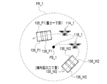
- the second shooting range determination unit 102 determines the shooting range including the region where the damage is relatively large by the analysis of the first damage situation 127 as the second shooting range 136. ..
- the areas where the damage is relatively large are "Fuji 1-chome” and "Cotton fox hole 2" in which the first damage situation 127 was judged to be "great damage” by the first damage situation analysis model 126. It is a section 135 such as "Chome".
- the second shooting range determination unit 102 registers the latitude and longitude and the azimuth of a plurality of shooting points corresponding to the plurality of second shooting ranges 136_F1 covering the section 135_F1 of "Fuji 1-chome”.
- Information 71A_1 is prepared.
- the second shooting range determination unit 102 registers the latitude and longitude and the azimuth of a plurality of shooting points according to the plurality of second shooting ranges 136_W2 covering the section 135_W2 of the "cotton fox hole 2-chome".
- the range information 71B_1 is prepared. For example, 100 m shown in FIG. 3 is registered in the altitude items of the second shooting range information 71A_1 and 71B_1.
- the transmission control unit 103 transmits the second shooting range information 71A_1, which is the information of the second shooting range 136_F1 covering the section 135_F1 of "Fuji 1-chome", to the second drone 11A_1. Further, the transmission control unit 103 transmits the second shooting range information 71B_1, which is the information of the second shooting range 136_W2 covering the section 135_W2 of the “cotton cloth fox hole 2-chome”, to the second drone 11B_1. In this way, the second shooting range determination unit 102 determines the second shooting range 136 for each of the two second drones 11A_1 and 11B_1.
- the flight controller 65 of the second drone 11A_1 sets the second drone 11A_1 as a section of “Fuji 1-chome” according to the second shooting range information 71A_1. Fly to each shooting point of 135_F1 in order.
- the camera controller 66 of the second drone 11A_1 shoots the second shooting range 136_F1 at each shooting point, and shoots a plurality of second aerial shot images 26.
- the flight controller 65 of the second drone 11B_1 makes the second drone 11B_1 fly to each shooting point of the section 135_W2 of the "cotton cloth fox hole 2-chome" in order according to the second shooting range information 71B_1.
- the camera controller 66 of the second drone 11B_1 shoots the second shooting range 136_W2 at each shooting point, and shoots a plurality of second aerial shot images 26.
- the second shooting range 136 is a range relatively narrower than the first shooting range 80, as can be seen by comparing with the first shooting range 80 shown in FIG.
- the second photographing range 136 is a range having a size of, for example, 1/5 to 1/10 of the first photographing range 80.
- the second damage situation analysis unit 104 has a building information adding unit 140, a building image cutting unit 141, and a second processing unit 142.
- the building information giving unit 140 assigns building information 144 to each building reflected in the second aerial image 26 with reference to the map 143 with building information, and assigns the second aerial image 26 to the second sky with building information.
- the captured image is 26I.
- the building information adding unit 140 outputs the second aerial image 26I with building information to the building image cutting unit 141.
- the map 143 with building information is stored in the storage 85, is read from the storage 85 by the RW control unit 100, and is output to the building information giving unit 140.
- the map 143 with building information is a three-dimensional map of the area 20, and the feature points such as the corners of the roof and the building information 144 are associated with each building.
- the building information 144 is specifically the name of the owner of the building (house) such as "Fuji Kazuo" or the name of the building such as "Fuji No. 1 Building".
- the building information 144 also includes the address of the building.
- the building information adding unit 140 is based on the latitude and longitude, direction, altitude of the second drone 11 when the second aerial image 26 is taken, the tilt angle of the second camera 37, and the like, and the building information-attached map 143 of the building. Align the orientation with the orientation of the building in the second aerial image 26. Further, the building information adding unit 140 extracts feature points such as corners of the roof of the building shown in the second aerial image 26. The building information adding unit 140 matches the map 143 with building information and the second aerial image 26 according to the orientation of the building reflected in the second aerial image 26, and matches the feature points of the map 143 with building information and the second. The position where the correlation with the feature point of the aerial image 26 is the highest is searched for. Then, at the position where the correlation is the highest, the building information 144 of the map 143 with building information is given to each building of the second aerial image 26.
- the building image cutting unit 141 uses, for example, a machine learning model (not shown) that uses an aerial image as an input image and an image of each house in the aerial image as an output image, and uses a second aerial image with building information.
- a building image 145 is cut out from the image 26I.
- the building image cutting unit 141 outputs a building image group 146 including a plurality of sets of the building image 145 and the building information 144 to the second processing unit 142.
- the second processing unit 142 inputs the building image 145 into the second damage situation analysis model 147. Then, the second damage situation 148 is output from the second damage situation analysis model 147.
- the second damage situation 148 assumes an earthquake or the like as a disaster, and is one of "total destruction", “half destruction", and "safety”.
- the second processing unit 142 outputs the second damage situation 148 from the second damage situation analysis model 147 for all the building images 145 included in the building image group 146.
- the second processing unit 142 outputs the second analysis result 111 summarizing the second damage situation 148 for each building.
- the second damage situation analysis model 147 is a machine learning model constructed by a method such as a neural network, a support vector machine, and boosting, like the first damage situation analysis model 126.
- the second damage situation analysis model 147 is stored in the storage 85, is read from the storage 85 by the RW control unit 100, and is output to the second processing unit 142.
- the second damage situation analysis model 147 is trained by being given the learning data 150.
- the learning data 150 is a set of a learning building image 145L and a correct answer second damage situation 148CA corresponding to the learning building image 145L.
- the learning building image 145L is obtained by inputting the second aerial image 26 of a certain area 20 into the building image cutting unit 141.
- Correct answer 2nd damage situation 148CA is the result of actually discriminating the 2nd damage situation 148 of the building shown in the learning building image 145L by a qualified person such as a house damage certified person.
- the building image for learning 145L is input to the second damage situation analysis model 147.
- the second damage situation analysis model 147 outputs the second damage situation 148L for learning to the building image 145L for learning.
- the loss calculation of the second damage situation analysis model 147 using the loss function is performed.
- various coefficients of the second damage situation analysis model 147 are updated according to the result of the loss calculation, and the second damage situation analysis model 147 is updated according to the update setting.
- the input of the building image 145L for learning to the second damage situation analysis model 147 the output of the second damage situation 148L for learning from the second damage situation analysis model 147, and the loss.
- the above-mentioned series of processes of calculation, update setting, and update of the second damage situation analysis model 147 are repeatedly performed while the learning data 150 is exchanged.
- the repetition of the above series of processes ends when the discrimination accuracy of the learning second damage situation 148L with respect to the correct answer second damage situation 148CA reaches a predetermined set level.
- the second damage situation analysis model 147 whose discrimination accuracy has reached the set level is stored in the storage 85 and used by the second processing unit 142.
- the damage status display screen 112 displayed on the display 15 of the client terminal 14 has a damage status display area 155 for each building and a statistical damage status display area 156.
- the damage status display area 155 for each building the building information 144, the building image 145, and the second damage status 148 of each building are displayed.
- the statistical damage status display area 156 the total number of buildings in each of the completely destroyed, partially destroyed, and safely buildings in the area 20 is displayed.
- the confirmation button 157 is selected, the display of the damage status display screen 112 is turned off.
- the damage status display area 155 and / or the statistical damage status display area 156 for each building may be displayed separately for each flight range FR or for each section 135.
- the CPU 87 of the disaster information processing server 12 has the RW control unit 100, the first damage situation analysis unit 101, and the second shooting. It functions as a range determination unit 102, a transmission control unit 103, a second damage status analysis unit 104, and a screen distribution control unit 105.
- the first damage situation analysis unit 101 includes a section image cutting unit 120 and a first processing unit 121.
- the second damage situation analysis unit 104 includes a building information adding unit 140, a building image cutting unit 141, and a second processing unit 142.
- the first shooting range 80 is shot by the first camera 36 mounted on the first drone 10 as shown in FIG. 7 according to the first shooting range information 70 shown in FIG. This gives the first aerial image 25.
- the first aerial image 25 is transmitted from the first drone 10 to the disaster information processing server 12.
- the RW control unit 100 accepts the first aerial image 25 from the first drone 10 (step ST100).
- the first aerial image 25 is stored in the storage 85 by the RW control unit 100.
- the first aerial image 25 is read from the storage 85 by the RW control unit 100 and output to the first damage status analysis unit 101.
- the first damage situation analysis unit 101 analyzes the first damage situation 127 of the disaster in the first shooting range 80 based on the first aerial image 25 (step ST110). ..
- the first damage situation analysis unit 101 analyzes the first damage situation 127 for each section 135 including a plurality of adjacent buildings.
- the analysis result of the first damage situation 127 that is, the first analysis result 110 is output from the first damage situation analysis unit 101 to the second shooting range determination unit 102.
- the second shooting range determination unit 102 determines the second shooting range 136 of the second camera 37 of the second drone 11 based on the first analysis result 110 (step ST120). At this time, the second shooting range determination unit 102 determines the shooting range including the region where the damage is relatively large by the analysis of the first damage situation 127 as the second shooting range 136. Further, the flight altitude of the second drone 11 is set lower than that of the first drone 10 by the second shooting range determination unit 102. Further, the second shooting range determination unit 102 determines the second shooting range 136 for each of the two second drones 11.
- the second shooting range information 71 which is the information of the second shooting range 136, is output from the second shooting range determination unit 102 to the transmission control unit 103. Then, the second shooting range information 71 is transmitted to the second drone 11 by the transmission control unit 103 (step ST130).
- the second shooting range 136 is shot by the second camera 37 mounted on the second drone 11 as shown in FIG. 13, whereby the second aerial shot image 26 is captured. can get.
- the second aerial image 26 is transmitted from the second drone 11 to the disaster information processing server 12.
- the RW control unit 100 accepts the second aerial image 26 from the second drone 11 (step ST200).
- the second aerial image 26 is stored in the storage 85 by the RW control unit 100.
- the second aerial image 26 is read from the storage 85 by the RW control unit 100 and output to the second damage status analysis unit 104. Then, as shown in FIG. 14, the second damage situation analysis unit 104 analyzes the second damage situation 148 of the disaster in the second shooting range 136 based on the second aerial image 26 (step ST210). ..
- the analysis result of the second damage situation 148 that is, the second analysis result 111 is output from the second damage situation analysis unit 104 to the RW control unit 100, and is stored in the storage 85 by the RW control unit 100.
- the second analysis result 111 is read from the storage 85 by the RW control unit 100 and output to the screen distribution control unit 105. Then, the screen distribution control unit 105 generates the damage status display screen 112 shown in FIG. 16 based on the second analysis result 111.
- the screen data of the damage status display screen 112 is distributed to the client terminal 14 of the distribution request source by the screen distribution control unit 105 (step ST220).
- the damage status display screen 112 is displayed on the display 15 of the client terminal 14 of the distribution request source, and is used for viewing by the staff of the disaster countermeasures headquarters.
- the CPU 87 of the disaster information processing server 12 includes a RW control unit 100, a first damage situation analysis unit 101, and a second shooting range determination unit 102.
- the RW control unit 100 receives the first aerial image 25 obtained by photographing the first photographing range 80 including the area 20 by the first camera 36 mounted on the first drone 10.
- the first damage situation analysis unit 101 analyzes the first damage situation 127 of the disaster in the first shooting range 80 based on the first aerial image 25.
- the second shooting range determination unit 102 is the second shooting range 136 of the second camera 37 mounted on the second drone 11 based on the first analysis result 110, and is relatively relative to the first shooting range 80. A narrow second shooting range 136 is determined.
- the first damage situation 127 which is the rough damage situation of the disaster
- the first aerial image 25 which captures the relatively wide first shooting range 80. ..
- the second shooting range 136 for grasping the second damage situation 148 which is the detailed damage situation of the disaster, is determined. Therefore, it is possible to grasp the damage situation at the disaster site in a short time without waste, as compared with the case where a plurality of drones are simply flown without any target.
- the second shooting range determination unit 102 determines the shooting range including the area of the area 20 where the damage is relatively large by the analysis of the first damage situation 127 as the second shooting range 136. Areas where the damage is considered to be relatively large are likely to include disaster sites. Therefore, it is possible to more efficiently grasp the damage situation at the disaster site.
- the RW control unit 100 receives the second aerial image 26 obtained by photographing the second shooting range 136 with the second camera 37 of the second drone 11.
- the second damage situation analysis unit 104 analyzes the second damage situation 148 of the disaster in the second shooting range 136 based on the second aerial image 26. Therefore, it is possible to easily grasp the second damage situation 148, which is more detailed than the first damage situation 127, without conducting a complicated investigation of actually walking around the disaster site.
- the second shooting range determination unit 102 sets the flight altitude of the second drone 11 lower than that of the first drone 10. Therefore, the performance of the second camera 37 is higher than that of the first camera 36, and the zoom magnification of the second camera 37 is not set to the telephoto side of the first camera 36, and the first aerial image 25 is taken.
- the first damage situation analysis unit 101 analyzes the first damage situation 127 for each section 135 including a plurality of adjacent buildings. Therefore, the analysis of the first damage situation 127 can be completed in a shorter time than the analysis of the first damage situation 127 of each building. As a result, the dispatch timing of the second drone 11 can be advanced.
- the second shooting range determination unit 102 determines the second shooting range 136 for each of the plurality of second drones 11. Therefore, it is possible to grasp the damage situation at the disaster site in a shorter time than in the case of one second drone 11.
- the second shooting range 136 may be relatively narrowed.
- the first damage situation 127 may be analyzed for each building.
- the number of the second drones 11 in charge of one flight range FR may be one or three or more.
- the first damage situation 127 either "large damage” or “small damage” was mentioned, but it is not limited to this. You may output the first damage status 127 of three or more stages, such as one of "extreme damage”, “medium damage”, and “small damage”. Further, the degree of damage may be output as a numerical value of, for example, 1 to 10.
- the second damage situation 148 is analyzed based only on the second aerial image 26, but the present invention is not limited to this. As in the second embodiment shown in FIGS. 19 and 20, the second damage situation may be analyzed based on the first aerial image 25 in addition to the second aerial image 26.
- the building information giving unit 161 of the second damage situation analysis unit 160 of the second embodiment refers to the map 143 with building information, and in addition to the second aerial image 26, the second Building information 144 is also given to each building reflected in the 1 aerial image 25, and the first aerial image 25 is referred to as the first aerial image 25I with the building information.
- the building image cutting unit 162 cuts out the first building image 145A from the first aerial image 25I with building information, and cuts out the second building image 145B from the second aerial image 26I with building information.
- the second building image 145B is the same as the building image 145 of the first embodiment.
- the building image cutting unit 162 includes a first building image group 146A including a plurality of pairs of the first building image 145A and the building information 144, and a second building image group including a plurality of pairs of the second building image 145B and the building information 144. 146B is output to the second processing unit 163.
- the second processing unit 163 inputs the first building image 145A and the second building image 145B associated with the same building information 144 into the second damage situation analysis model 164. Then, the second damage situation 165 is output from the second damage situation analysis model 164.
- the second damage situation 165 is one of "total destruction", “half destruction”, and "safety” as in the second damage situation 148 of the first embodiment.
- the second processing unit 163 causes the second damage to all the first building image 145A and the second building image 145B to which the same building information 144 is associated, which are included in the first building image group 146A and the second building image group 146B.
- the second damage situation 165 is output from the situation analysis model 164.
- the first building image 145A and the second building image 145B to which the same building information 144 is not associated are input to the second damage situation analysis model 147 of the first embodiment and the second damage situation 148 is output. ..
- the second damage situation analysis model 164 is given learning data 170 and learned.
- the learning data 170 is a combination of the learning first building image 145AL and the learning second building image 145BL, and the correct answer second damage situation 165CA corresponding to the learning first building image 145AL and the learning second building image 145BL.
- the first building image 145AL for learning is obtained by inputting the first aerial image 25 of a certain area 20 into the building image cutting unit 162.
- the second building image 145BL for learning is obtained by inputting the second aerial image 26 of a certain area 20 into the building image cutting unit 162.
- Correct answer 2nd damage situation 165CA is the result of actually determining the 2nd damage situation 165 of the building shown in the learning 1st building image 145AL and the learning 2nd building image 145BL by a qualified person such as a resident damage certified person. be.
- the learning first building image 145AL and the learning second building image 145BL are input to the second damage situation analysis model 164.
- the second damage situation analysis model 164 outputs the second damage situation 165L for learning to the first building image 145AL for learning and the second building image 145BL for learning.
- the loss calculation of the second damage situation analysis model 164 using the loss function is performed.
- various coefficients of the second damage situation analysis model 164 are updated according to the result of the loss calculation, and the second damage situation analysis model 164 is updated according to the update setting.
- the first building image 145AL for learning and the second building image 145BL for learning are input to the second damage situation analysis model 164, and learning from the second damage situation analysis model 164.
- the above series of processes of output of the second damage situation 165L, loss calculation, update setting, and update of the second damage situation analysis model 164 are repeatedly performed while the learning data 170 is exchanged.
- the repetition of the above series of processes ends when the discrimination accuracy of the learning second damage situation 165L for the correct answer second damage situation 165CA reaches a predetermined set level.
- the second damage situation analysis model 164 whose discrimination accuracy has reached the set level is stored in the storage 85 and used by the second processing unit 163.
- the second damage situation analysis unit 160 analyzes the second damage situation 165 based on the first aerial image 25 in addition to the second aerial image 26. Since the building is relatively smaller in the first aerial image 25 than in the second aerial image 26, the resolution of the building is inferior to that of the second aerial image 26. However, the first aerial image 25 may show the building at a different angle from the second aerial image 26, and it may be easier to grasp the second damage situation 165 than the second aerial image 26. Therefore, there is a high possibility that the second damage situation 165 of the building, which is not clear only from the second aerial image 26, can be grasped, and as a result, the reliability of the second analysis result 111 can be improved.
- the second drone 11 is directed to the area where the damage of another flight range FR is relatively large.
- the first damage situation analysis unit 101 analyzes that the first damage situation 127 of the sections 135_1, 135_2, 135_3, and 135_4 is “damaged”.
- the second flight range FR_2 consider the case where the first damage situation 127 does not have the "large damage" section 135.
- the second shooting range determination unit 102 first determines a plurality of shooting ranges 136_1 that cover the section 135_1 as the second shooting range 136 of the second drone 11A_1. Further, the second shooting range determination unit 102 determines a plurality of shooting ranges 136_2 that cover the section 135_2 as the second shooting range 136 of the second drone 11B_1.
- the second shooting range determination unit 102 determines a plurality of shooting ranges 136_3 covering the section 135_3 as the second shooting range 136 of the second drone 11A_2 in charge of the second flight range FR_2. Further, the second shooting range determination unit 102 determines a plurality of shooting ranges 136_4 covering the section 135_4 as the second shooting range 136 of the second drone 11B_2 in charge of the second flight range FR_2.
- the second drones 11A_2 and 11B_2 are examples of the "subject second drone" according to the technique of the present disclosure.
- first flight range FR_1 is an example of "a flight range different from the flight range of the target second drone" according to the technique of the present disclosure
- second flight range FR_1 is the "flying range FR_1" according to the technique of the present disclosure. This is an example of "the flight range of the target second drone”.
- compartments 135_3 and 135_4 are examples of "areas considered to be relatively large in damage” according to the technique of the present disclosure.
- the second shooting range determination unit 102 is determined to have relatively little damage in the area within the flight range FR of the target second drone 11 by the analysis of the first damage situation 127.
- the shooting range including the area where the damage is relatively large is included. Is determined as the second shooting range 136 of the target second drone 11. Therefore, it is possible to effectively utilize the second drone 11 having a flight range FR, which is said to have relatively small damage. As a result, it is possible to grasp the damage situation in the area where the damage is relatively large in a shorter time.
- the second drone 11 but also the first drone 10 may be sent to support.
- the first camera 36 it is preferable to use a camera having high performance such as resolution so that each building of the first aerial image 25 can be clearly captured.
- the second camera 37 does not have to have the same performance as the first camera 36.
- the first aerial image 25 and the second aerial image 26 may be transmitted to the disaster information processing server 12 by wire after the first drone 10 and the second drone 11 land on the departure / arrival base FB.
- the flight range FR is not limited to the three examples. It may be one or two places, or four or more places. Further, the shape of the flight range FR is not limited to a circle. It may be oval or rectangular.
- the section 135 including a plurality of adjacent buildings is not limited to the illustrated chome.
- a rectangular area of a predetermined size with a road as a boundary may be used as a section 135.
- the first camera 36 and the second camera 37 assume a visible light camera, but the present invention is not limited to this.
- an infrared camera may be prepared for shooting in the evening and at night.
- the second damage situation one of "total destruction”, “half destruction”, and “safety” is given, but it is not limited to this, mainly assuming an earthquake as a disaster. .. Assuming flood damage as a disaster, any one of “inundation above the floor”, “inundation under the floor”, and “safety” may be output as the second damage situation. Further, assuming a large-scale fire as a disaster, any one of "burnt", “half-burned”, and "safe” may be output as the second damage situation.
- a second damage situation analysis model may be prepared according to the type of disaster, and the second damage situation analysis model may be used properly according to the type of disaster.
- the RW control unit 100 the first damage status analysis unit 101, the second shooting range determination unit 102, the transmission control unit 103, the second damage status analysis units 104 and 160, and the screen distribution control unit 105.
- a processing unit that executes various processes such as a section image cutting unit 120, a first processing unit 121, a building information giving unit 140 and 161, a building image cutting unit 141 and 162, and a second processing unit 142 and 163.
- various processors shown below can be used.
- processors for various processors, as described above, in addition to the CPU 87, which is a general-purpose processor that executes software (operation program 95) and functions as various processing units, after manufacturing an FPGA (Field Programmable Gate Array) or the like.
- Dedicated processor with a circuit configuration specially designed to execute specific processing such as programmable logic device (PLD), ASIC (Application Specific Integrated Circuit), which is a processor whose circuit configuration can be changed. Includes electrical circuits and the like.
- One processing unit may be composed of one of these various processors, or may be a combination of two or more processors of the same type or different types (for example, a combination of a plurality of FPGAs and / or a CPU). It may be configured in combination with FPGA). Further, a plurality of processing units may be configured by one processor.
- one processor is configured by a combination of one or more CPUs and software, as represented by a computer such as a client and a server.
- the processor functions as a plurality of processing units.
- SoC System On Chip
- SoC system On Chip
- the various processing units are configured by using one or more of the above-mentioned various processors as a hardware-like structure.
- an electric circuit in which circuit elements such as semiconductor elements are combined can be used.
- the technique of the present disclosure can be appropriately combined with the various embodiments described above and / or various modifications. Further, it is of course not limited to each of the above embodiments, and various configurations can be adopted as long as they do not deviate from the gist.
- the present application has described an embodiment using a multicopter type drone, the form of the drone may be an airplane, a rotary wing aircraft, a glider, an airship, or the like as long as it is an unmanned aerial vehicle.
- a and / or B is synonymous with "at least one of A and B". That is, “A and / or B” means that it may be A alone, B alone, or a combination of A and B. Further, in the present specification, when three or more matters are connected and expressed by "and / or", the same concept as “A and / or B" is applied.
Landscapes
- Engineering & Computer Science (AREA)
- Multimedia (AREA)
- Signal Processing (AREA)
- Physics & Mathematics (AREA)
- General Physics & Mathematics (AREA)
- Theoretical Computer Science (AREA)
- Remote Sensing (AREA)
- Business, Economics & Management (AREA)
- Emergency Management (AREA)
- Alarm Systems (AREA)
- Management, Administration, Business Operations System, And Electronic Commerce (AREA)
Priority Applications (2)
| Application Number | Priority Date | Filing Date | Title |
|---|---|---|---|
| JP2022553737A JP7641980B2 (ja) | 2020-10-01 | 2021-09-07 | 災害情報処理装置、災害情報処理装置の作動方法、災害情報処理装置の作動プログラム、並びに災害情報処理システム |
| US18/191,669 US12207021B2 (en) | 2020-10-01 | 2023-03-28 | Disaster information processing apparatus, operation method of disaster information processing apparatus, operation program of disaster information processing apparatus, and disaster information processing system |
Applications Claiming Priority (2)
| Application Number | Priority Date | Filing Date | Title |
|---|---|---|---|
| JP2020-167014 | 2020-10-01 | ||
| JP2020167014 | 2020-10-01 |
Related Child Applications (1)
| Application Number | Title | Priority Date | Filing Date |
|---|---|---|---|
| US18/191,669 Continuation US12207021B2 (en) | 2020-10-01 | 2023-03-28 | Disaster information processing apparatus, operation method of disaster information processing apparatus, operation program of disaster information processing apparatus, and disaster information processing system |
Publications (1)
| Publication Number | Publication Date |
|---|---|
| WO2022070808A1 true WO2022070808A1 (ja) | 2022-04-07 |
Family
ID=80950157
Family Applications (1)
| Application Number | Title | Priority Date | Filing Date |
|---|---|---|---|
| PCT/JP2021/032903 Ceased WO2022070808A1 (ja) | 2020-10-01 | 2021-09-07 | 災害情報処理装置、災害情報処理装置の作動方法、災害情報処理装置の作動プログラム、並びに災害情報処理システム |
Country Status (3)
| Country | Link |
|---|---|
| US (1) | US12207021B2 (https=) |
| JP (1) | JP7641980B2 (https=) |
| WO (1) | WO2022070808A1 (https=) |
Cited By (4)
| Publication number | Priority date | Publication date | Assignee | Title |
|---|---|---|---|---|
| JP2025108157A (ja) * | 2024-01-10 | 2025-07-23 | Necプラットフォームズ株式会社 | 画像分析装置、画像分析方法、およびプログラム |
| WO2025205777A1 (ja) * | 2024-03-29 | 2025-10-02 | 富士フイルム株式会社 | 情報処理装置、情報処理方法及びプログラム |
| WO2026053820A1 (ja) * | 2024-09-03 | 2026-03-12 | 富士フイルム株式会社 | 情報処理装置、情報処理方法、プログラム、及び情報処理システム |
| JP7854486B1 (ja) | 2024-10-18 | 2026-05-01 | Ntt東日本株式会社 | 監視システム |
Families Citing this family (3)
| Publication number | Priority date | Publication date | Assignee | Title |
|---|---|---|---|---|
| JP7468523B2 (ja) * | 2019-06-05 | 2024-04-16 | ソニーグループ株式会社 | 移動体、位置推定方法、およびプログラム |
| WO2022070981A1 (ja) * | 2020-10-01 | 2022-04-07 | 富士フイルム株式会社 | 災害情報処理装置、災害情報処理装置の作動方法、災害情報処理装置の作動プログラム、並びに災害情報処理システム |
| US20250115380A1 (en) * | 2023-10-04 | 2025-04-10 | The Boeing Company | Methods and apparatus for onboard camera calibration |
Citations (5)
| Publication number | Priority date | Publication date | Assignee | Title |
|---|---|---|---|---|
| JP2004056664A (ja) * | 2002-07-23 | 2004-02-19 | Ntt Data Corp | 共同撮影システム |
| WO2012169232A1 (ja) * | 2011-06-08 | 2012-12-13 | オムロン株式会社 | 分散画像処理システム |
| WO2013051300A1 (ja) * | 2011-10-03 | 2013-04-11 | Hanabata Mitsuaki | 被災状況把握システム |
| JP2019047755A (ja) * | 2017-09-11 | 2019-03-28 | Kddi株式会社 | 管理装置、プログラム、管理方法及び飛行装置 |
| WO2019235415A1 (ja) * | 2018-06-04 | 2019-12-12 | 全力機械株式会社 | 災害状況判定システムおよび災害判定飛行システム |
Family Cites Families (1)
| Publication number | Priority date | Publication date | Assignee | Title |
|---|---|---|---|---|
| JP2013134663A (ja) | 2011-12-27 | 2013-07-08 | Mitsubishi Heavy Ind Ltd | 災害活動支援システム及び方法 |
-
2021
- 2021-09-07 WO PCT/JP2021/032903 patent/WO2022070808A1/ja not_active Ceased
- 2021-09-07 JP JP2022553737A patent/JP7641980B2/ja active Active
-
2023
- 2023-03-28 US US18/191,669 patent/US12207021B2/en active Active
Patent Citations (5)
| Publication number | Priority date | Publication date | Assignee | Title |
|---|---|---|---|---|
| JP2004056664A (ja) * | 2002-07-23 | 2004-02-19 | Ntt Data Corp | 共同撮影システム |
| WO2012169232A1 (ja) * | 2011-06-08 | 2012-12-13 | オムロン株式会社 | 分散画像処理システム |
| WO2013051300A1 (ja) * | 2011-10-03 | 2013-04-11 | Hanabata Mitsuaki | 被災状況把握システム |
| JP2019047755A (ja) * | 2017-09-11 | 2019-03-28 | Kddi株式会社 | 管理装置、プログラム、管理方法及び飛行装置 |
| WO2019235415A1 (ja) * | 2018-06-04 | 2019-12-12 | 全力機械株式会社 | 災害状況判定システムおよび災害判定飛行システム |
Cited By (4)
| Publication number | Priority date | Publication date | Assignee | Title |
|---|---|---|---|---|
| JP2025108157A (ja) * | 2024-01-10 | 2025-07-23 | Necプラットフォームズ株式会社 | 画像分析装置、画像分析方法、およびプログラム |
| WO2025205777A1 (ja) * | 2024-03-29 | 2025-10-02 | 富士フイルム株式会社 | 情報処理装置、情報処理方法及びプログラム |
| WO2026053820A1 (ja) * | 2024-09-03 | 2026-03-12 | 富士フイルム株式会社 | 情報処理装置、情報処理方法、プログラム、及び情報処理システム |
| JP7854486B1 (ja) | 2024-10-18 | 2026-05-01 | Ntt東日本株式会社 | 監視システム |
Also Published As
| Publication number | Publication date |
|---|---|
| US12207021B2 (en) | 2025-01-21 |
| JPWO2022070808A1 (https=) | 2022-04-07 |
| US20230239437A1 (en) | 2023-07-27 |
| JP7641980B2 (ja) | 2025-03-07 |
Similar Documents
| Publication | Publication Date | Title |
|---|---|---|
| US12207021B2 (en) | Disaster information processing apparatus, operation method of disaster information processing apparatus, operation program of disaster information processing apparatus, and disaster information processing system | |
| US20250124797A1 (en) | Flight control for flight-restricted regions | |
| JP7040827B1 (ja) | 捜索支援システムおよび救助支援プログラム | |
| JP2011052999A (ja) | 飛翔体探知方法及びシステムならびにプログラム | |
| WO2019095288A1 (en) | System and methods for electronic fences | |
| CN109661694B (zh) | 控制无人飞行器飞行的方法和设备、限飞区生成方法和设备 | |
| JP2026016667A (ja) | 無人飛行体のフライト管理サーバ及びフライト管理システム | |
| JP2026042834A (ja) | 移動体の移動経路生成方法及びプログラム、管理サーバ、管理システム | |
| US20190346842A1 (en) | Transferring annotations to images captured by remote vehicles between displays | |
| WO2022070956A1 (ja) | 情報処理装置、情報処理方法、プログラム、及び情報収集システム | |
| Suzuki et al. | Real-time hazard map generation using small unmanned aerial vehicle | |
| JP2025111687A (ja) | 無人飛行体のフライト管理サーバ及びフライト管理システム | |
| JP2025003621A (ja) | 飛行体の飛行経路表示方法及び情報処理装置 | |
| KR20190075635A (ko) | 위경 고도 좌표계를 기반으로 하는 비행 모델의 입체영상 생성 장치 및 그 방법 | |
| JP2026012840A (ja) | 移動体の移動経路生成方法及びプログラム、管理サーバ、管理システム | |
| KR102526202B1 (ko) | 실내 자율 비행 드론 제어 시스템 및 그 방법 | |
| WO2021005782A1 (ja) | 飛行体の管理サーバ及び管理システム | |
| Saadat et al. | An application framework for forest fire and haze detection with data acquisition using unmanned aerial vehicle | |
| US20240005770A1 (en) | Disaster information processing apparatus, disaster information processing system, disaster information processing method, and program | |
| Velasco et al. | Development of uavs/drones equipped with thermal sensors for the search of individuals lost under rubble due to earthquake collapses or any eventuality requiring such capabilities | |
| WO2021079516A1 (ja) | 飛行体の飛行経路作成方法及び管理サーバ | |
| JP6810497B1 (ja) | 飛行体の飛行経路作成方法及び管理サーバ | |
| RU2260209C1 (ru) | Способ охранной сигнализации с использованием видеонаблюдения | |
| WO2021064982A1 (ja) | 情報処理装置および情報処理方法 | |
| JP6810498B1 (ja) | 飛行体の飛行経路作成方法及び管理サーバ |
Legal Events
| Date | Code | Title | Description |
|---|---|---|---|
| 121 | Ep: the epo has been informed by wipo that ep was designated in this application |
Ref document number: 21875110 Country of ref document: EP Kind code of ref document: A1 |
|
| ENP | Entry into the national phase |
Ref document number: 2022553737 Country of ref document: JP Kind code of ref document: A |
|
| NENP | Non-entry into the national phase |
Ref country code: DE |
|
| 122 | Ep: pct application non-entry in european phase |
Ref document number: 21875110 Country of ref document: EP Kind code of ref document: A1 |