WO2022070698A1 - 有機性排水の嫌気処理装置 - Google Patents
有機性排水の嫌気処理装置 Download PDFInfo
- Publication number
- WO2022070698A1 WO2022070698A1 PCT/JP2021/031356 JP2021031356W WO2022070698A1 WO 2022070698 A1 WO2022070698 A1 WO 2022070698A1 JP 2021031356 W JP2021031356 W JP 2021031356W WO 2022070698 A1 WO2022070698 A1 WO 2022070698A1
- Authority
- WO
- WIPO (PCT)
- Prior art keywords
- fermenter
- sludge
- pipe
- anaerobic treatment
- pipes
- Prior art date
- Legal status (The legal status is an assumption and is not a legal conclusion. Google has not performed a legal analysis and makes no representation as to the accuracy of the status listed.)
- Ceased
Links
Images

Classifications
-
- C—CHEMISTRY; METALLURGY
- C02—TREATMENT OF WATER, WASTE WATER, SEWAGE, OR SLUDGE
- C02F—TREATMENT OF WATER, WASTE WATER, SEWAGE, OR SLUDGE
- C02F1/00—Treatment of water, waste water, or sewage
- C02F1/44—Treatment of water, waste water, or sewage by dialysis, osmosis or reverse osmosis
-
- C—CHEMISTRY; METALLURGY
- C02—TREATMENT OF WATER, WASTE WATER, SEWAGE, OR SLUDGE
- C02F—TREATMENT OF WATER, WASTE WATER, SEWAGE, OR SLUDGE
- C02F3/00—Biological treatment of water, waste water, or sewage
- C02F3/28—Anaerobic digestion processes
Definitions
- the present invention relates to an anaerobic treatment device for organic wastewater, and more particularly to an apparatus for obtaining treated water by membrane separation after anaerobic treatment of organic wastewater.
- Patent Document 1 describes an anaerobic treatment method in which organic wastewater is anaerobically treated in a fermenter, sludge is circulated between the fermenter and a membrane separation device installed outside the tank, and treated water is obtained by membrane filtration. , It is described that sludge is extracted from the middle layer of the fermenter, circulated to the membrane separation device, and excess sludge is extracted from the lower layer.
- the supply of high-density inorganic solids and impurities accumulated in the fermenter to the membrane separation device is suppressed, so that membrane clogging is suppressed and excess sludge is used. Can be preferentially discharged.
- sludge is a non-Newtonian fluid (pseudoplastic fluid) that becomes easier to flow as the flow becomes stronger. Therefore, when sludge is circulated in an internal pressure type tubular membrane at a large flow rate and cross-flow filtered, the membrane is separated from the fermenter.
- An object of the present invention is to provide an anaerobic treatment device for organic wastewater, which can efficiently stir in a fermenter and obtain high treatment efficiency.
- the organic wastewater is anaerobically treated in a cylindrical fermenter, and sludge is circulated between the fermenter and the membrane separation device installed outside the fermenter.
- a plurality of mud pipes for sending sludge from the fermentation tank to the membrane separation device are connected to the fermenter.
- a plurality of return pipes for returning concentrated sludge from the membrane separation device into the fermenter are connected to the fermenter, and in the plan view of the fermenter, the circumferential positions of the mud feed pipes are different, and the return pipes of each return pipe are different.
- the circumferential position is different, and a mud-feeding pipe switching means for switching the mud-feeding pipe for flowing out sludge from the fermenter and a return pipe switching means for switching the return pipe for flowing concentrated sludge into the fermenter are provided. It is characterized by being.
- the mud feed pipe and the return pipe are connected so as to be in the radial direction with respect to the outer peripheral surface of the fermenter.
- the crossing angle between the mud feeding pipes adjacent to each other in the circumferential direction and the crossing angle between the return pipes are 45 ° or more, respectively.
- the mud feed pipe switching means switches the mud feed pipe so as to select one sludge feed pipe that feeds sludge from the fermenter.
- the return pipe switching means switches the return pipe so as to select one mud feed pipe for returning the concentrated sludge to the fermenter.
- the mud feed pipe is connected to the vicinity of the vertical middle portion of the fermenter, and the return pipe is connected to the upper part of the fermenter.
- a portion for taking out excess sludge is provided in the lower part of the fermenter.
- a plurality of sludge feeding pipes for flowing sludge from the fermenter and return pipes for flowing concentrated sludge from the membrane separation device into the fermenter are provided at different circumferential positions. ing. Then, by switching the sludge feeding pipe used for the sludge feeding and the returning pipe used for returning the concentrated sludge into the fermenter by the switching means, the position of taking out the sludge from the fermenter can be switched, and the concentrated sludge from the membrane separation device can be switched. The inflow position into the fermenter can be switched. As a result, local sludge retention in the fermenter is prevented, and anaerobic treatment is efficiently performed in the entire fermenter.
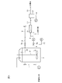
- FIG. 1 It is a block diagram of the anaerobic treatment apparatus of organic waste water which concerns on embodiment.
- A is a sectional view taken along line AA of FIG. 1
- B is a sectional view taken along line BB of FIG.
- the fermenter has a vertical cross section.
- the organic wastewater (raw water) is introduced into the fermenter 3 equipped with the stirrer 2 through the raw water pipe 1 having the raw water pump P1.
- the tips of two mud feed pipes 4 and 5 are connected near the middle of the fermenter 3 in the vertical direction (in the middle range of 15% or more and 70% or less from the bottom when the effective water depth of the fermenter 3 is 100%).
- Valves 4a and 5a are provided in each of the pipes 4 and 5.
- the rear ends of the mud feed pipes 4 and 5 are connected to one end of the collective pipe 6.
- a circulation pump P2 is provided in the collecting pipe 6.
- the other end of the collecting pipe 6 is connected to the inlet portion on the primary side of the internal pressure type tubular membrane module (hereinafter referred to as internal pressure type tubular membrane) 7 as a membrane separation device.
- a plurality of tubulars 7a are installed in the internal pressure type tubular membrane 7, and sludge circulates in the tubular 7a.
- the collective return pipe 8 and the return pipes 9 and 10 are provided.
- Valves 9a and 10a are provided in the return pipes 9 and 10.
- One end of the collective return pipe 8 is connected to the primary side outlet portion of the internal pressure type tubular membrane 7, and the rear ends of the return pipes 9 and 10 are connected to the other end.
- the tips of the return pipes 9 and 10 are connected to the upper part of the fermenter 3 (the range of the effective water depth above the middle range).
- the permeated water that has passed through the tubular 7a flows into the treatment water tank 12 through the pipe 11 and is taken out through the pipe 13.
- a backwash pipe 14 and a backwash pump P3 are provided so as to backwash the internal pressure type tubular membrane 7 with the treated water in the treated water tank 12.
- a surplus sludge extraction pipe 15 is provided in the lower part of the fermenter 3 (below the middle range), and a surplus sludge pump P4 is provided in the pipe 15.
- the mud feed pipes 4 and 5 are provided at substantially the same height
- the return pipes 9 and 10 are provided at substantially the same height.
- the tip sides of the mud feed pipes 4 and 5 and the return pipes 9 and 10 are connected so as to be in the radial direction with respect to the outer peripheral wall surface of the fermenter 3, respectively. Therefore, the extension line on the tip side of the pipes 4, 5, 9, and 10 passes substantially in the center of the fermenter 3.
- intersection angle ⁇ 1 of the mud feed pipes 4 and 5 and the intersection angle ⁇ 2 of the return pipes 9 and 10 (the intersection angle of each of the above extension lines) in the plan view of the fermenter 3 are 45 ° or more, preferably 60, respectively. It is above °.
- intersection angles ⁇ 1 and ⁇ 2 may be 180 °. That is, the mud feed pipes 4 and 5 may be located on opposite sides of the center of the fermenter 3, and the return pipes 9 and 10 may be located on opposite sides of the center of the fermenter 3.
- each valve may be manually opened and closed.
- valves 4a and 5a When one of the valves 4a and 5a is open, the other is closed. When one of the valves 9a and 10a is open, the other is closed. That is, the mud is always fed by one mud feed pipe 4 or 5, and is returned by one return pipe 9 or 10.
- the valves 4a, 5a and 9a, 10a are opened and closed periodically, preferably every 1 to 24 hours, and particularly preferably every 2 to 6 hours.
- the crossing angles ⁇ 1 and ⁇ 2 are equal, the mud feed pipe 4 is located below the return pipe 9, and the mud feed pipe 5 is located below the return pipe 10. Then, the opening and closing of the valves 4a and 9a are synchronized, and the opening and closing of the valves 5a and 10a are synchronized. That is, when the valve 4a is opened, the valve 9a is opened, and when the valve 5a is opened, the valve 10a is opened. Further, when the valve 4a is closed, the valve 9a is closed, and when the valve 5a is closed, the valve 10a is closed.
- the fermenter membrane separation device, suitable operating conditions, etc. will be described below.
- the fermenter 3 has a CODcr tank load of 5 to 20 kg / m 3 / d (particularly 6 to 12 kg / m 3 / d), and the concentration of sludge in the tank (sludge supplied to the membrane) is 10,000 to 50,000 mgSS. / L, particularly 20,000 to 30,000 mg / L, is preferable in terms of a good balance between organic matter removal and membrane filterability.
- the fermenter 3 may be any of medium-temperature fermentation at 25 to 40 ° C., preferably 30 to 38 ° C., and high-temperature fermentation at 45 to 60 ° C., preferably 50 to 58 ° C.
- the pH in the tank is preferably 6.5 to 8.0, particularly 6.8 to 7.4, and if necessary, a sludge circulation line (particularly a collective return pipe) to the outer membrane of the tank (internal pressure type tubular membrane 7).
- the pH is adjusted by adding an alkaline agent such as NaOH or NaOH3 or an acid agent such as HCl to 8 or the return pipes 9, 10).
- the cross-sectional shape of the fermenter is circular, the height is 5 to 20 m, preferably 8 to 15 m, and the ratio of the inner diameter to the height (effective water depth) is 1: 0.5 to 1: 5, especially 1: It is preferably 1.5 to 1: 3.
- the fermenter 3 may have a structure that narrows the upper part and the lower part.
- the fermenter may be equipped with a stirrer such as an impeller type with a center layout or a screw type installed on the side.
- a stirrer such as an impeller type with a center layout or a screw type installed on the side.
- a drawing pipe 16 for excess sludge at a height of 0 to 2 m, preferably 0.3 to 1.5 m from the bottom of the fermenter.
- the drawing may be performed from the side surface of the fermenter, but it is preferable to extend the internal pipe to the vicinity of the center of the tank and pull out.
- the membrane separation device (internal pressure type tubular membrane in this embodiment) is a membrane module in which a plurality of (for example, 100 to 1000) tubulars having a diameter of 3 mm to 10 mm are filled therein, and sludge flows inside each tubular. The permeated water seeps out of the tubular, and the permeated water seeped out from each tubular is collected and discharged from the membrane module as treated water.
- the pore size of the membrane is preferably 0.01 to 1 ⁇ m, particularly preferably 0.03 to 0.1 ⁇ m.
- the membrane permeation flux of the treated water is preferably 0.1 to 0.8 m / d, particularly preferably about 0.2 to 0.5 m / d.
- the modules may be arranged in series, in parallel, or both, but when arranged in series, the sludge flow direction is reversed so that coarse solid particles do not accumulate between the modules. It is preferable that the sludge in the connection pipe between the modules is returned to the fermenter without going through the modules.
- ⁇ Mud pipe and return pipe> It is preferable to provide 2 to 5 mud pipes and 2 to 3 return pipes, respectively.
- the cross angle between the mud feed pipes adjacent to each other in the circumferential direction and the cross angle between the return pipes are 45 ° or more in the plan view of the fermenter.
- the heights of the mud feed pipes and the heights of the return pipes may be the same or different.
- the positions of the mud feed pipe and the return pipe that simultaneously pass mud may be different, but the same is preferable in that a swirling flow is formed in the fermenter.
- Examples 1 to 3, reference example 1 In the anaerobic treatment device consisting of the fermentation tank 3 shown in FIGS. 1 and 2 and the membrane separation device (internal pressure type tubular membrane 7) installed outside the tank, the intersection angles ⁇ 1 and ⁇ 2 are changed as shown in Table 1, and the valve 4a , 5a and valves 9a, 10a were operated so as to be switched every 4 hours, and the processing performance was compared and evaluated for each month.
- the opening and closing of the valve 4a and the opening and closing of the valve 9a were synchronized, and the opening and closing of the valve 5a and the opening and closing of the valve 10a were synchronized.
- LiCl was put in from the raw water pipe and a tracer test was conducted to determine the dead space ratio in the fermenter.
- the larger the dead space the smaller the apparent volume of the reaction tank. Therefore, a tracer substance is added for quantification, stirred for a predetermined time, and the concentration of the tracer substance in the sludge taken out from the sludge circulation pipe is measured.
- the dead space rate was calculated according to the degree of dilution.
- Table 1 shows the average value of the CODcr removal rate during each period and the ratio of dead space in the fermenter obtained by the tracer test.
Landscapes
- Life Sciences & Earth Sciences (AREA)
- Microbiology (AREA)
- Hydrology & Water Resources (AREA)
- Engineering & Computer Science (AREA)
- Environmental & Geological Engineering (AREA)
- Water Supply & Treatment (AREA)
- Chemical & Material Sciences (AREA)
- Organic Chemistry (AREA)
- Biodiversity & Conservation Biology (AREA)
- Separation Using Semi-Permeable Membranes (AREA)
- Purification Treatments By Anaerobic Or Anaerobic And Aerobic Bacteria Or Animals (AREA)
- Treatment Of Sludge (AREA)
Abstract
発酵槽内の撹拌を効率よく行うことができ、高い処理効率を得ることができる有機性排水の嫌気処理装置が提供される。有機性排水(原水)は、原水ポンプP1を有する原水配管1を通って撹拌機2を備えた発酵槽3内に導入される。発酵槽3の中位付近に送泥配管4,5が接続され、上部に返送配管9,10が接続されている。送泥配管4又は5で送泥された汚泥は内圧式管状膜7で膜分離され、濃縮汚泥が返送配管9又は10で返送される。送泥配管4,5の交角θ1及び返送配管9,10の交角θ2が45~180°である。
Description
本発明は、有機性排水の嫌気処理装置に関するものであり、特に、有機性排水を嫌気処理した後、膜分離によって処理水を得る装置に関する。
特許文献1に、有機性排水を発酵槽にて嫌気処理し、発酵槽と槽外に設置された膜分離装置との間で汚泥を循環させて膜濾過によって処理水を得る嫌気性処理方法において、発酵槽の中層部から汚泥を引き抜き、膜分離装置に循環するとともに、低層部から余剰汚泥を引き抜くことが記載されている。
この処理方法によると、発酵槽内に蓄積する比重の大きい無機性固形物や夾雑物などが膜分離装置に供給されることが抑制されるので、膜閉塞が抑制されるとともに、それらを余剰汚泥として優先的に排出することができる。
上記の嫌気性処理方法では発酵槽内の汚泥濃度を高めることによって、高負荷、高効率の処理が可能となるが、汚泥濃度が高くなると汚泥の粘性が高まり、発酵槽内の撹拌混合が不充分となって処理効率が低下する問題があった。特に、汚泥は流れが強くなるほど流動し易くなる非ニュートン流体(擬塑性流体)であるため、内圧式管状膜に汚泥を大流量で循環してクロスフロー濾過する場合では、発酵槽内から膜分離装置への汚泥の引抜き部や戻り部での流速が著しく高くなって粘性が低下する一方、そこから遠く、循環水の流入水流が届かない領域では流動しにくく粘性が高まって汚泥同士が固着してゲル状になり、通水が行き届かなくなりデッドスペースとなり、発酵槽内で偏流が生じる問題があった。このデッドスペースにより反応槽のみかけ容積は低下する。
撹拌機により発酵槽内全体を混合するように撹拌すると、比重の大きい無機性固形物や夾雑物も膜分離装置に供給され易くなる。
本発明は、発酵槽内の撹拌を効率よく行うことができ、高い処理効率を得ることができる有機性排水の嫌気処理装置を提供することを課題とする。
本発明の有機性排水の嫌気処理装置は、有機性排水を円筒型発酵槽にて嫌気処理し、該発酵槽と該発酵槽外に設置された膜分離装置との間で汚泥を循環させ、該膜分離装置での膜濾過によって処理水を得る有機性排水の嫌気処理装置において、該発酵槽から汚泥を膜分離装置に送泥する送泥配管が該発酵槽に複数本接続されており、膜分離装置から濃縮汚泥を発酵槽内に返送する返送配管が該発酵槽に複数本接続されており、該発酵槽の平面視において、各送泥配管の周方向位置が異なり、各返送配管の周方向位置が異なっており、該発酵槽内から汚泥を流出させる送泥配管を切り替える送泥配管切り替え手段と、該発酵槽内に濃縮汚泥を流入させる返送配管を切り替える返送配管切り替え手段とが設けられていることを特徴とする。
本発明の一態様では、前記送泥配管及び返送配管は、前記発酵槽の外周面に対し放射方向となるように接続されている。
本発明の一態様では、前記発酵槽の平面視において、周方向に隣り合う送泥配管同士の交角及び返送配管同士の交角がそれぞれ45°以上である。
本発明の一態様では、前記送泥配管切り替え手段は、発酵槽から汚泥を送り出す1本の送泥配管を選択するように送泥配管を切り替えるものである。
本発明の一態様では、前記返送配管切り替え手段は、発酵槽に濃縮汚泥を返送する1本の送泥配管を選択するように返送配管を切り替えるものである。
本発明の一態様では、前記送泥配管は、発酵槽の上下方向中間部付近に接続され、返送配管は発酵槽の上部に接続されている。
本発明の一態様では、前記発酵槽の下部に、余剰汚泥の取出部が設けられている。
本発明の有機性排水の嫌気処理装置では、発酵槽から汚泥を流出させる送泥配管及び膜分離装置からの濃縮汚泥を該発酵槽に流入させる返送配管をそれぞれ周方向位置を異ならせて複数設けている。そして、送泥に用いる送泥配管及び発酵槽内への濃縮汚泥返送に用いる返送配管を切り替え手段で切り替えることにより、発酵槽内からの汚泥の取り出し位置を切り替え、また膜分離装置からの濃縮汚泥の発酵槽内への流入位置を切り替えることができる。この結果、発酵槽内の局所的な汚泥滞留が防止され、発酵槽内の全体で効率よく嫌気処理が行われる。
以下、図1,2を参照して実施の形態に係る有機性排水の嫌気処理装置の構成について説明する。なお、図1では、発酵槽を縦断面としている。
有機性排水(原水)は、原水ポンプP1を有する原水配管1を通って撹拌機2を備えた発酵槽3内に導入される。
発酵槽3の上下方向の中間付近(発酵槽3の有効水深を100%とした場合、下から15%以上70%以下の中位範囲)に2本の送泥配管4,5の先端が接続されている。各配管4,5に弁4a,5aが設けられている。送泥配管4,5の後端は集合配管6の一端に接続されている。集合配管6に循環ポンプP2が設けられている。集合配管6の他端は、膜分離装置としての内圧式管状膜モジュール(以下、内圧式管状膜という。)7の一次側の入口部に接続されている。
内圧式管状膜7内には、複数本のチューブラ7aが設置されており、汚泥はチューブラ7a内を流通する。チューブラ7aを透過しなかった濃縮汚泥を発酵槽3に返送するために、集合返送配管8及び返送配管9,10が設けられている。返送配管9,10に弁9a,10aが設けられている。
集合返送配管8の一端は、内圧式管状膜7の一次側出口部に接続されており、他端に返送配管9,10の後端が接続されている。返送配管9,10の先端は、発酵槽3の上部(前記の中位範囲よりも上側の有効水深の範囲)に接続されている。
チューブラ7aを透過した透過水は、配管11を通って処理水槽12に流入し、配管13を通って取り出される。処理水槽12内の処理水で内圧式管状膜7を逆洗するように逆洗配管14及び逆洗ポンプP3が設けられている。
発酵槽3の下部(前記中位範囲よりも下側)に余剰汚泥の引抜配管15が設けられ、該配管15に余剰汚泥ポンプP4が設けられている。
この実施の形態では、送泥配管4,5は略同一高さに設けられ、返送配管9,10は略同一高さに設けられている。送泥配管4,5及び返送配管9,10の先端側は、それぞれ発酵槽3の外周壁面に対し放射方向となるように接続されている。従って、該配管4,5,9,10の先端側の延長線は、発酵槽3のほぼ中心を通る。
この実施の形態では、発酵槽3の平面視における送泥配管4,5の交角θ1及び返送配管9,10の交角θ2(各々の上記延長線の交角)は、それぞれ45°以上、好ましくは60°以上である。
交角θ1,θ2は180°であってもよい。即ち、送泥配管4,5は発酵槽3の中心を挟んで反対側に位置してもよく、返送配管9,10は発酵槽3の中心を挟んで反対側に位置してもよい。
この実施の形態では、各弁4a,5a,9a,10aの開閉を切り替えるための制御器(図示略)が設けられているが、手動にて各弁の開閉操作を行ってもよい。
弁4a,5aは、一方が開となっているときは他方が閉とされる。弁9a,10aは、一方が開となっているときは他方が閉とされる。即ち、常に1本の送泥配管4又は5によって送泥され、1本の返送配管9又は10によって返送される。弁4a,5a及び弁9a,10aはそれぞれ定期的に、好ましくは1~24時間毎に、特に好ましくは2~6時間毎に、開閉が切り替えられる。
この実施の形態では、上記交角θ1,θ2は等しく、返送配管9の下方に送泥配管4が位置し、返送配管10の下方に送泥配管5が位置している。そして、弁4a、9aの開閉を同期させ、弁5a、10aの開閉を同期させる。すなわち、弁4aを開とするときには弁9aを開とし、弁5aを開とするときには弁10aを開とする。また、弁4aを閉とするときには弁9aを閉とし、弁5aを閉とするときには弁10aを閉とする。このように発酵槽3からの汚泥流出部位と返送濃縮汚泥の流入部位とを平面視において揃えることにより、発酵槽3内に旋回流が形成され易くなる。
以下に、発酵槽、膜分離装置及び好適な運転条件等について説明する。
<発酵槽>
発酵槽3は、CODcr槽負荷5~20kg/m3/d(特に6~12kg/m3/d)であり、槽内汚泥(膜に供給する汚泥)の濃度は10,000~50,000mgSS/L、特に20,000~30,000mg/Lであることが、有機物除去と膜濾過性のバランスがよい点で好ましい。発酵槽3は、25~40℃、好ましくは30~38℃の中温発酵、45~60℃、好ましくは50~58℃の高温発酵のいずれでもよい。
槽内pHは6.5~8.0、特に6.8~7.4であることが好ましく、必要に応じて槽外膜(内圧式管状膜7)への汚泥循環ライン(特に集合返送配管8又は返送配管9,10)にNaOH、NaHCO3などのアルカリ剤やHClなどの酸剤を添加してpH調整を行う。
発酵槽3は、CODcr槽負荷5~20kg/m3/d(特に6~12kg/m3/d)であり、槽内汚泥(膜に供給する汚泥)の濃度は10,000~50,000mgSS/L、特に20,000~30,000mg/Lであることが、有機物除去と膜濾過性のバランスがよい点で好ましい。発酵槽3は、25~40℃、好ましくは30~38℃の中温発酵、45~60℃、好ましくは50~58℃の高温発酵のいずれでもよい。
槽内pHは6.5~8.0、特に6.8~7.4であることが好ましく、必要に応じて槽外膜(内圧式管状膜7)への汚泥循環ライン(特に集合返送配管8又は返送配管9,10)にNaOH、NaHCO3などのアルカリ剤やHClなどの酸剤を添加してpH調整を行う。
発酵槽の断面形状は円形であり、高さは5~20m、好ましくは8~15mであり、内径と高さ(有効水深)との比は1:0.5~1:5、特に1:1.5~1:3であることが好ましい。なお、発酵槽3は、上部及び下部を窄めるような構造でもよい。
発酵槽にセンターレイアウトのインペラ式、側面設置のスクリュー式のような撹拌機を設けてもよい。
発酵槽の底部から0~2m、好ましくは0.3~1.5mの高さに余剰汚泥の引抜配管16を設けることが好ましい。引抜きは発酵槽側面から行ってもよいが、内部配管を槽中央部付近まで延ばして引き抜くことが好ましい。
<膜分離装置>
膜分離装置(この実施の形態では内圧式管状膜)は、直径3mm~10mmのチューブラが内部に複数(例えば100~1000本)充填された膜モジュールであり、汚泥は各チューブラの内部を流れる。透過水がチューブラ外に浸み出し、各チューブラから浸み出した透過水が集められ、膜モジュールから処理水として排出される。膜の細孔径は0.01~1μm、特に0.03~0.1μmが好ましい。
膜分離装置(この実施の形態では内圧式管状膜)は、直径3mm~10mmのチューブラが内部に複数(例えば100~1000本)充填された膜モジュールであり、汚泥は各チューブラの内部を流れる。透過水がチューブラ外に浸み出し、各チューブラから浸み出した透過水が集められ、膜モジュールから処理水として排出される。膜の細孔径は0.01~1μm、特に0.03~0.1μmが好ましい。
発酵槽から汚泥をチューブラ内の流速が0.5~2m/sec、好ましくは0.8~1.5m/secとなる流量で流すことが好ましい。
処理水の膜透過流束(フラックス)は0.1~0.8m/d、特に0.2~0.5m/d程度が好ましい。
10~60分の濾過に対し、5~30秒間の頻度で、フラックス4~10m/dで処理水による逆洗を行うことが好ましい。また、1~8時間毎に膜モジュールの通泥方向を反転することで、発酵槽内に流入したり、無機分の析出や膜面からの剥離などにより発酵槽内で生成した粗大な固形粒子が膜入口に蓄積し、流路を閉塞させることを防止し、安定した濾過性能を保つことができる。膜モジュールを複数用いる際は、モジュールを直列、並列のいずれ、または両方の配置で用いてよいが、直列に配置する際はモジュール間に粗大な固形粒子が蓄積しないように、通泥方向を反転する際に、モジュール間の接続配管中の汚泥がモジュールを介さずに発酵槽に返送されるような構成とするのが好ましい。
<送泥配管及び返送配管>
送泥配管及び返送配管は、それぞれ2~5本、特に2~3本設けることが好ましい。送泥配管及び返送配管をそれぞれ3本以上設ける場合、発酵槽の平面視において、周方向に隣り合う送泥配管同士の交角及び返送配管同士の交角がそれぞれ45°以上であることが好ましい。
送泥配管同士の高さ及び返送配管同士の高さは同じでも、異なっていてもよい。
送泥配管及び返送配管は、それぞれ2~5本、特に2~3本設けることが好ましい。送泥配管及び返送配管をそれぞれ3本以上設ける場合、発酵槽の平面視において、周方向に隣り合う送泥配管同士の交角及び返送配管同士の交角がそれぞれ45°以上であることが好ましい。
送泥配管同士の高さ及び返送配管同士の高さは同じでも、異なっていてもよい。
送泥配管及び返送配管は、汚泥循環による発酵槽の撹拌効果を高めるため、同時に通泥する配管は1本ずつとすることが好ましい。また、発酵槽の平面視において、同時に通泥する送泥配管と返送配管の位置は異なっていてもよいが、発酵槽内で旋回流を形成させる点で同じことが好ましい。
前述の通り1~24時間、好ましくは2~6時間ごとに通泥する配管を変更することが好ましい。
[実施例1~3、参考例1]
図1,2に示した発酵槽3と槽外に設置された膜分離装置(内圧式管状膜7)からなる嫌気処理装置において、交角θ1,θ2を表1のように変えて、また弁4a,5a及び弁9a,10aの開閉を4時間ごとに切り替えるようにして運転を行い、処理性能を1ヶ月間ずつ比較評価した。なお、弁4aの開閉と弁9aの開閉を同期させ、弁5aの開閉と弁10aの開閉を同期させた。
図1,2に示した発酵槽3と槽外に設置された膜分離装置(内圧式管状膜7)からなる嫌気処理装置において、交角θ1,θ2を表1のように変えて、また弁4a,5a及び弁9a,10aの開閉を4時間ごとに切り替えるようにして運転を行い、処理性能を1ヶ月間ずつ比較評価した。なお、弁4aの開閉と弁9aの開閉を同期させ、弁5aの開閉と弁10aの開閉を同期させた。
LiClを原水配管から投入してトレーサー試験を行い、発酵槽内のデッドスペース率を求めた。デッドスペースが大きいほど反応槽のみかけ容積は小さくなるため、定量するためにトレーサー物質を入れて、所定時間だけ攪拌し、汚泥循環配管から取り出した汚泥中のトレーサー物質の濃度を測り、トレーサー物質の希釈の程度によってデッドスペース率を計算した。
原水、発酵槽及び内圧式管状膜として下記のものを用いた。
<原水>
電子部品製造工場の高濃度排液(CODcr濃度40,000mg/L)に栄養塩類として窒素、リン、および、鉄、コバルト、ニッケルなどの微量金属類を添加したもの
水量40m3/d
電子部品製造工場の高濃度排液(CODcr濃度40,000mg/L)に栄養塩類として窒素、リン、および、鉄、コバルト、ニッケルなどの微量金属類を添加したもの
水量40m3/d
<発酵槽>
内径:5m
高さ(有効水深):10m
実容量:200m3
余剰汚泥引抜配管15の高さ:0.5m
送泥配管4,5の高さ:2m
返送配管9,10の高さ:0.5m
温度:35℃
槽内汚泥濃度:25,000~30,000mg/L
槽内pH:7.2~7.5
余剰汚泥引抜量:平均1.8m3/d(SRT110日)、引き抜いた汚泥は脱水処理
内径:5m
高さ(有効水深):10m
実容量:200m3
余剰汚泥引抜配管15の高さ:0.5m
送泥配管4,5の高さ:2m
返送配管9,10の高さ:0.5m
温度:35℃
槽内汚泥濃度:25,000~30,000mg/L
槽内pH:7.2~7.5
余剰汚泥引抜量:平均1.8m3/d(SRT110日)、引き抜いた汚泥は脱水処理
<内圧式管状膜>
内径5mmのPVDF製チューブラが約700本充填された長さ3mの内圧式管状膜モジュール6本(並列3本が直列に並んだ構成)からなる膜ユニット
膜面積:198m2
汚泥循環量:161m3/hr
膜の平均フラックス0.20m/d
内径5mmのPVDF製チューブラが約700本充填された長さ3mの内圧式管状膜モジュール6本(並列3本が直列に並んだ構成)からなる膜ユニット
膜面積:198m2
汚泥循環量:161m3/hr
膜の平均フラックス0.20m/d
[比較例1]
送泥配管5及び返送配管10を省略し、送泥配管4及び返送配管9のみを設置したこと以外は上記実施例と同一条件で運転を行った。
送泥配管5及び返送配管10を省略し、送泥配管4及び返送配管9のみを設置したこと以外は上記実施例と同一条件で運転を行った。
それぞれの期間中のCODcr除去率の平均値、および、トレーサー試験により求めた発酵槽内のデッドスペースの比率を表1に示す。

[考察]
参考例1及び比較例1ではデッドスペース率が約20%に達し、CODcr除去率が約90%に留まったのに対し、実施例1~3ではデッドスペースが10%以下に低減され、発酵槽がより有効に利用された結果、97%以上のCODcr除去率を得ることができた。
参考例1及び比較例1ではデッドスペース率が約20%に達し、CODcr除去率が約90%に留まったのに対し、実施例1~3ではデッドスペースが10%以下に低減され、発酵槽がより有効に利用された結果、97%以上のCODcr除去率を得ることができた。
以上の実施例及び比較例より、本発明によると、発酵槽外に設置された内圧式管状膜に汚泥を循環してクロスフロー濾過する嫌気処理装置において、膜への循環流を利用した発酵槽内の撹拌を効率よく行うことができ、高い処理効率が得られるようになることが認められた。
本発明を特定の態様を用いて詳細に説明したが、本発明の意図と範囲を離れることなく様々な変更が可能であることは当業者に明らかである。
本出願は、2020年9月29日付で出願された日本特許出願2020-163642に基づいており、その全体が引用により援用される。
本出願は、2020年9月29日付で出願された日本特許出願2020-163642に基づいており、その全体が引用により援用される。
3 発酵槽
4,5 送泥配管
7 内圧式管状膜
9,10 返送配管
4,5 送泥配管
7 内圧式管状膜
9,10 返送配管
Claims (7)
- 有機性排水を円筒型発酵槽にて嫌気処理し、該発酵槽と該発酵槽外に設置された膜分離装置との間で汚泥を循環させ、該膜分離装置での膜濾過によって処理水を得る有機性排水の嫌気処理装置において、
該発酵槽から汚泥を膜分離装置に送泥する送泥配管が該発酵槽に複数本接続されており、
膜分離装置から濃縮汚泥を発酵槽内に返送する返送配管が該発酵槽に複数本接続されており、
該発酵槽の平面視において、各送泥配管の周方向位置が異なり、各返送配管の周方向位置が異なっており、
該発酵槽内から汚泥を流出させる送泥配管を切り替える送泥配管切り替え手段と、該発酵槽内に濃縮汚泥を流入させる返送配管を切り替える返送配管切り替え手段とが設けられている
ことを特徴とする有機性排水の嫌気処理装置。 - 前記送泥配管及び返送配管は、前記発酵槽の外周面に対し放射方向となるように接続されている、請求項1の有機性排水の嫌気処理装置。
- 前記発酵槽の平面視において、周方向に隣り合う送泥配管同士の交角及び返送配管同士の交角がそれぞれ45°以上である、請求項2の有機性排水の嫌気処理装置。
- 前記送泥配管切り替え手段は、発酵槽から汚泥を送り出す1本の送泥配管を選択するように送泥配管を切り替えるものである、請求項1~3のいずれかの有機性排水の嫌気処理装置。
- 前記返送配管切り替え手段は、発酵槽から濃縮汚泥を返送する1本の送泥配管を選択するように返送配管を切り替えるものである、請求項1~4のいずれかの有機性排水の嫌気処理装置。
- 前記送泥配管は、発酵槽の上下方向中間部付近に接続され、返送配管は発酵槽の上部に接続されている、請求項1~5のいずれかの有機性排水の嫌気処理装置。
- 前記発酵槽の下部に、余剰汚泥の取出部が設けられている、請求項1~6のいずれかの有機性排水の嫌気処理装置。
Applications Claiming Priority (2)
| Application Number | Priority Date | Filing Date | Title |
|---|---|---|---|
| JP2020-163642 | 2020-09-29 | ||
| JP2020163642A JP7196887B2 (ja) | 2020-09-29 | 2020-09-29 | 有機性排水の嫌気処理装置 |
Publications (1)
| Publication Number | Publication Date |
|---|---|
| WO2022070698A1 true WO2022070698A1 (ja) | 2022-04-07 |
Family
ID=80951328
Family Applications (1)
| Application Number | Title | Priority Date | Filing Date |
|---|---|---|---|
| PCT/JP2021/031356 Ceased WO2022070698A1 (ja) | 2020-09-29 | 2021-08-26 | 有機性排水の嫌気処理装置 |
Country Status (2)
| Country | Link |
|---|---|
| JP (1) | JP7196887B2 (ja) |
| WO (1) | WO2022070698A1 (ja) |
Citations (3)
| Publication number | Priority date | Publication date | Assignee | Title |
|---|---|---|---|---|
| JPH11169875A (ja) * | 1997-12-08 | 1999-06-29 | Nippon Nogyo Shuraku Haisui Kyokai | 汚水の生物処理方法及び装置 |
| JP2001170631A (ja) * | 1999-12-22 | 2001-06-26 | Kubota Corp | 膜型反応槽の攪拌方法および装置 |
| JP2010207762A (ja) * | 2009-03-12 | 2010-09-24 | Kubota Corp | 膜型メタン発酵処理装置およびメタン発酵処理方法 |
Family Cites Families (3)
| Publication number | Priority date | Publication date | Assignee | Title |
|---|---|---|---|---|
| JPH08290044A (ja) * | 1995-04-20 | 1996-11-05 | Mitsui Zosen Eng Kk | 膜処理装置 |
| KR101032608B1 (ko) * | 2010-11-30 | 2011-05-06 | 현대건설주식회사 | 유기성 폐기물 처리장치 |
| JP6359310B2 (ja) * | 2014-03-27 | 2018-07-18 | 株式会社クボタ | 水処理装置および水処理方法 |
-
2020
- 2020-09-29 JP JP2020163642A patent/JP7196887B2/ja active Active
-
2021
- 2021-08-26 WO PCT/JP2021/031356 patent/WO2022070698A1/ja not_active Ceased
Patent Citations (3)
| Publication number | Priority date | Publication date | Assignee | Title |
|---|---|---|---|---|
| JPH11169875A (ja) * | 1997-12-08 | 1999-06-29 | Nippon Nogyo Shuraku Haisui Kyokai | 汚水の生物処理方法及び装置 |
| JP2001170631A (ja) * | 1999-12-22 | 2001-06-26 | Kubota Corp | 膜型反応槽の攪拌方法および装置 |
| JP2010207762A (ja) * | 2009-03-12 | 2010-09-24 | Kubota Corp | 膜型メタン発酵処理装置およびメタン発酵処理方法 |
Also Published As
| Publication number | Publication date |
|---|---|
| JP2022055926A (ja) | 2022-04-08 |
| JP7196887B2 (ja) | 2022-12-27 |
Similar Documents
| Publication | Publication Date | Title |
|---|---|---|
| CN103068747B (zh) | 用于处理废物流的厌氧膜生物反应器 | |
| US20150218012A1 (en) | Water treatment process comprising floatation combined with gravity filtration, and corresponding equipment | |
| US10807023B2 (en) | Method for the treatment of water and wastewater | |
| CN117049755B (zh) | 一种煤制气废水的中水回用处理工艺 | |
| CN102659285B (zh) | 白酒生产废水一体化处理装置 | |
| CN106145566A (zh) | 一种pcb板油墨废水净化处理系统 | |
| CN214829522U (zh) | 一种高效沉淀单元和污水处理系统 | |
| CN101928072B (zh) | 一体化去除水中硬度的设备 | |
| CN104445835B (zh) | 一种适用于小城镇垃圾渗滤液处理的方法及系统 | |
| CN203700070U (zh) | 一种钢铁废水和市政污水混合再生回用的装置 | |
| WO2022070698A1 (ja) | 有機性排水の嫌気処理装置 | |
| CN109384340A (zh) | 气化废水组合处理系统及方法 | |
| CN109231619A (zh) | 一种页岩气压裂返排废水的处理系统及工艺 | |
| JP2007532297A (ja) | 浸漬膜のスループット及び動作寿命を改善する方法および装置 | |
| CN208603896U (zh) | 一种疏浚船用海水淡化装置预处理系统 | |
| CN208200478U (zh) | 一种高效沉淀池 | |
| CN109110967B (zh) | 一种基于膜化学反应器的铝土矿选矿废水回用系统及方法 | |
| NO813255L (no) | Fremgangsmaate og apparat for behandling av avvann | |
| CN205442948U (zh) | 一种气升式金属膜mbr装置 | |
| CN210711057U (zh) | 絮凝和转鼓式微滤机去除藻类水华的设备 | |
| CN211620040U (zh) | 一种臭氧催化氧化反应器 | |
| CN208980532U (zh) | 电镀废水高效处理系统 | |
| CN217972902U (zh) | 一种vcm废水高效处理装置 | |
| CN206156961U (zh) | 一种pcb板油墨废水净化处理系统 | |
| CN121573836A (zh) | 煤矿井开采污水处理系统及方法 |
Legal Events
| Date | Code | Title | Description |
|---|---|---|---|
| 121 | Ep: the epo has been informed by wipo that ep was designated in this application |
Ref document number: 21875001 Country of ref document: EP Kind code of ref document: A1 |
|
| NENP | Non-entry into the national phase |
Ref country code: DE |
|
| 122 | Ep: pct application non-entry in european phase |
Ref document number: 21875001 Country of ref document: EP Kind code of ref document: A1 |