WO2022070669A1 - 粒子解析装置およびその製造方法 - Google Patents
粒子解析装置およびその製造方法 Download PDFInfo
- Publication number
- WO2022070669A1 WO2022070669A1 PCT/JP2021/030761 JP2021030761W WO2022070669A1 WO 2022070669 A1 WO2022070669 A1 WO 2022070669A1 JP 2021030761 W JP2021030761 W JP 2021030761W WO 2022070669 A1 WO2022070669 A1 WO 2022070669A1
- Authority
- WO
- WIPO (PCT)
- Prior art keywords
- liquid
- lid
- hole
- plate
- liquid space
- Prior art date
- Legal status (The legal status is an assumption and is not a legal conclusion. Google has not performed a legal analysis and makes no representation as to the accuracy of the status listed.)
- Ceased
Links
Images






Classifications
-
- G—PHYSICS
- G01—MEASURING; TESTING
- G01N—INVESTIGATING OR ANALYSING MATERIALS BY DETERMINING THEIR CHEMICAL OR PHYSICAL PROPERTIES
- G01N15/00—Investigating characteristics of particles; Investigating permeability, pore-volume or surface-area of porous materials
- G01N15/10—Investigating individual particles
- G01N15/1031—Investigating individual particles by measuring electrical or magnetic effects
- G01N15/12—Investigating individual particles by measuring electrical or magnetic effects by observing changes in resistance or impedance across apertures when traversed by individual particles, e.g. by using the Coulter principle
-
- G—PHYSICS
- G01—MEASURING; TESTING
- G01N—INVESTIGATING OR ANALYSING MATERIALS BY DETERMINING THEIR CHEMICAL OR PHYSICAL PROPERTIES
- G01N15/00—Investigating characteristics of particles; Investigating permeability, pore-volume or surface-area of porous materials
- G01N15/10—Investigating individual particles
- G01N15/1031—Investigating individual particles by measuring electrical or magnetic effects
-
- G—PHYSICS
- G01—MEASURING; TESTING
- G01N—INVESTIGATING OR ANALYSING MATERIALS BY DETERMINING THEIR CHEMICAL OR PHYSICAL PROPERTIES
- G01N27/00—Investigating or analysing materials by the use of electric, electrochemical, or magnetic means
Definitions
- the present invention relates to a particle analysis device for analyzing particles contained in a liquid.
- Patent Documents 1 to 4 In order to analyze particles such as exosomes, pollen, viruses, and bacteria, a particle analysis device having two spaces has been proposed (Patent Documents 1 to 4).
- This type of particle analyzer has holes connecting the two spaces, one of which stores the liquid and the other of which contains the liquid containing the particles to be analyzed. Different potentials are applied to these spaces, and electrophoresis causes particles to pass through the pores. As the particles pass through the pores, the value of the current flowing through the liquid changes. By observing changes in the current value, the characteristics (eg, type, shape, size) of the particles that have passed through the pores are analyzed. For example, it is possible to count the number of certain types of particles contained in a liquid.
- the particle analyzer disclosed in Patent Document 4 has two inlet holes and two outlet holes for two kinds of liquids stored in two spaces.
- a syringe or pipette can be used to introduce the liquid into the space through the inlet hole.
- the present invention provides a particle analysis device capable of preventing the liquid used for analysis from scattering to the outside, and a method for easily manufacturing this device.
- the particle analyzer has an upper liquid space in which the first liquid is stored, a lower liquid space in which the second liquid is stored below the upper liquid space, and the upper liquid space. It has a connection hole connecting the lower liquid space and an opening opened on the upper surface of the particle analyzer, extends from the upper surface to the upper liquid space, and transfers the first liquid to the upper liquid space.
- a first inlet hole for supplying and a first outlet hole having an opening opened at the upper surface, extending from the upper surface to the upper liquid space, and discharging air from the upper liquid space.
- a second inlet hole extending from the upper surface to the lower liquid space and supplying the second liquid to the lower liquid space, and an opening at the upper surface.
- a second outlet hole extending from the upper surface to the lower liquid space and discharging air from the lower liquid space, and a potential for the first liquid in the upper liquid space.
- the first liquid can be supplied to the upper liquid space through the first inlet hole.
- the air in the upper liquid space is discharged through the first outlet hole, facilitating the entry of the first liquid into the upper liquid space through the first inlet hole.
- the opening of the first outlet hole is provided with a first lid formed of a membrane that allows air to pass through but does not allow liquid to pass through. Therefore, even if the energy for introducing the first liquid into the upper liquid space is too strong, the first liquid is blocked by the first lid and does not scatter to the outside. Since the first lid allows the passage of air, it does not prevent the first liquid from entering the upper liquid space through the first inlet hole.
- the second liquid can be supplied to the lower liquid space through the second inlet hole.
- the opening of the second outlet hole is provided with a second lid formed of a membrane that allows air to pass through but does not allow liquid to pass through. Therefore, even if the energy for introducing the second liquid into the lower liquid space is too strong, the second liquid is blocked by the second lid and does not scatter to the outside.
- the second lid allows the passage of air and does not prevent the second liquid from entering the lower liquid space through the second inlet hole.
- FIG. 6 is a cross-sectional view taken along the line VII-VII of FIG.
- FIG. 6 is a perspective view which shows the particle analysis apparatus which concerns on 2nd Embodiment of this invention. It is an exploded view of the particle analysis apparatus of FIG. It is sectional drawing of a part of the particle analysis apparatus of FIG.
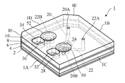
- the particle analysis apparatus 1 As shown in FIG. 1, the particle analysis apparatus 1 according to the 1st embodiment has a hexagonal column shape and has 6 side surfaces 1A, 1B, 1C, 1D, 1E, 1F. As shown in the plan view of FIG. 3, the particle analyzer 1 has a hexagonal contour with two substantially square corners cut out when viewed from above.
- FIG. 2 is a side view of the particle analyzer 1 showing the two side surfaces 1A and 1C.
- the particle analyzer 1 has an upper liquid space 20, a lower liquid space 22, and a connection hole 26.
- the liquid spaces 20 and 22 each extend straight in the horizontal direction, and the first liquid 37 is stored in the first liquid space 20 and the second liquid 38 is stored in the lower liquid space 22.
- the first liquid 37 stored in the upper liquid space 20 and the second liquid 38 stored in the lower liquid space 22 are shown by different hatching patterns.
- the lower liquid space 22 is arranged below the upper liquid space 20, and the liquid spaces 20 and 22 are connected to each other by a connecting hole 26.
- the liquid spaces 20 and 22 are orthogonal to each other.
- the particle analysis device 1 has a first inlet hole 20A, a first outlet hole 20B, a second inlet hole 22A, and a second outlet hole 22B.
- Each of the first inlet hole 20A, the first outlet hole 20B, the second inlet hole 22A, and the second outlet hole 22B has an opening that opens on the upper surface of the particle analyzer 1.
- the first inlet hole 20A and the first outlet hole 20B extend vertically from the upper surface of the particle analyzer 1 to the upper liquid space 20, and the first liquid 37 flows through these holes.
- the first inlet hole 20A, the first outlet hole 20B and the upper liquid space 20 form one storage tank for the first liquid 37.
- the first inlet hole 20A is used as an inlet for the first liquid 37
- the first outlet hole 20B is upward by the first liquid 37. It is used as an outlet for air extruded from the liquid space 20 of the.
- the second inlet hole 22A and the second outlet hole 22B extend vertically from the upper surface of the particle analyzer 1 to the liquid space 22 below, and the second liquid 38 flows through these holes.
- the second inlet hole 22A, the second outlet hole 22B and the lower liquid space 22 form another storage tank for the second liquid 38.
- the second inlet hole 22A is used as an inlet for the second liquid 38
- the second outlet hole 22B is provided by the second liquid 38. It is used as an outlet for air pushed out of the lower liquid space 22.
- the particle analysis device 1 has a first electrode 28 and a second electrode 30.
- the first electrode 28 applies a potential to the first liquid 37 in the upper liquid space 20 through the first outlet hole 20B.
- the second electrode 30 gives the second liquid 38 in the lower liquid space 22 through the second outlet hole 22B a potential different from that of the first electrode 28.
- the second electrode 30 is an anode and the first electrode 28 is a cathode. Since the liquid spaces 20 and 22 communicate with each other through the connection holes 26, a current flows through the first liquid 37 and the second liquid 38 inside the liquid spaces 20 and 22.
- FIG. 4 schematically shows the particle analysis principle using the particle analysis device 1.
- a first liquid 37 containing the particles 40 to be analyzed is stored in the upper liquid space 20.
- a second liquid 38 that originally does not contain the particles 40 is stored in the lower liquid space 22.
- the second liquid 38 stored in the lower liquid space 22 may contain the particles 40.
- the liquid spaces 20 and 22 are connected to each other by a connection hole 26 which is a through hole formed in the chip (nanopore chip) 24.
- a DC power supply 35 and an ammeter 36 are connected to the first electrode 28 and the second electrode 30.
- the DC power supply 35 is, for example, a battery, but is not limited to the battery.
- the particles 40 contained in the first liquid 37 of the upper liquid space 20 pass through the connection hole 26 and the second in the lower liquid space 22. Flows into the liquid 38 of.
- the current values flowing through the first liquid 37 and the second liquid 38 change.
- the change in the current value can be observed using the ammeter 36.
- the characteristics (for example, type, shape, size) of the particles 40 that have passed through the connection hole 26 are analyzed. For example, it is possible to measure the number of particles 40 of a certain type contained in the first liquid 37.
- the particle analyzer 1 can be used to analyze various particles such as exosomes, pollen, viruses, and bacteria.
- the particle analyzer 1 includes laminated hexagonal plates 2, 4, 6, 8 and 10.
- some or all of these plates are made of a transparent or translucent material and the cavity of the particle analyzer 1 (first inlet hole 20A, first outlet hole 20B, second inlet hole).
- the storage state of the first liquid 37 and the second liquid 38 in the 22A and the second outlet hole 22B, and the liquid spaces 20, 22) can be observed from the outside of the particle analyzer 1.
- the storage state of the liquid does not necessarily have to be observable, and these plates may be opaque.
- Plates 2, 4, 6, 8 and 10 are made of electrically and chemically inert and insulating materials.
- Each plate may be formed of a rigid material or an elastic material.
- Preferred rigid materials include resin materials such as polycarbonate, polyethylene terephthalate, acrylics, cyclic olefins, polypropylene, polystyrene, polyesters, polyvinyl chloride and the like.
- Preferred elastic materials include silicone rubber or urethane rubber containing an elastomer such as PDMS (polydimethylsiloxane).
- a plate made of a rigid material may be stacked on the plate made of an elastic material, or a plate made of an elastic material may be laminated. All of the plates 2, 4, 6, 8 and 10 may be formed of an elastic material.
- a horizontal groove 4g is formed in the center of the lower surface of the next plate 4.
- the groove 4g forms the lower liquid space 22.
- a communication hole 4t penetrating in the vertical direction is formed in the center of the groove 4g.
- the communication hole 4t communicates the lower liquid space 22 (groove 4g) with the connection hole 26 of the chip 24.
- the plate 4 is formed with cylindrical through holes 4a and 4d penetrating in the vertical direction.
- the through holes 4a and 4d have the same diameter.
- the through hole 4a communicates with one end of the groove 4g, and the through hole 4d communicates with the other end of the groove 4g.
- a rectangular parallelepiped recess 6h is formed in the center of the lower surface of the next plate 6.
- the recess 6h accommodates the chip 24 having the connection hole 26.
- the tip 24 is fitted in the recess 6h.
- the tip 24 may be removable (replaceable) or non-removable (non-replaceable) in the recess 6h.
- a horizontal groove 6g is formed in the center of the upper surface of the plate 6. When the plates 6 and 8 are joined, the groove 6g forms the upper liquid space 20.
- a communication hole 6t penetrating in the vertical direction is formed in the center of the groove 6g.
- the communication hole 6t communicates the upper liquid space 20 (groove 6g) with the connection hole 26 of the chip 24.
- the cross sections of the communication holes 4t and 6t and the connection hole 26 are circular, but they do not have to be circular.
- the plate 6 is formed with cylindrical through holes 6a and 6d penetrating in the vertical direction.
- the through holes 6a and 6d have the same diameter as the through holes 4a and 4d.
- the through hole 6a communicates with one end of the through hole 4a and thus the groove 4g of the plate 4 directly underneath, and the through hole 6d communicates with the other end of the through hole 4d and thus the groove 4g.
- the chip (nanopore chip) 24 is a rectangular parallelepiped, for example, a square plate. A connection hole 26 penetrating in the vertical direction is formed in the center of the chip 24.
- the chip 24 may be formed of an electrically and chemically inert and insulating material such as glass, sapphire, ceramics, resin, elastomer, SiO 2 , SiN, or Al 2 O 3 .
- the chip 24 is made of a material that is harder than the material of the plates 2, 4, 6, 8 and 10, such as glass, sapphire, ceramics, SiO 2 , SiN, or Al 2 O 3 , but resin or elastomer.
- the chip 24 may be formed with.
- the user can select an appropriate chip 24 according to the application of the particle analysis device 1.
- the particles 40 to be analyzed can be changed by preparing a plurality of chips 24 having connection holes 26 having different dimensions or shapes and selecting the chips 24 to be fitted in the recesses.
- the chip 24 is hydrophilized so that the liquid can easily pass through the connection hole 26 without being clogged.
- the hydrophilization treatment comprises, for example, irradiating the chip 24 with oxygen plasma or ultraviolet light. Ultraviolet rays may be emitted in the form of a laser beam.
- the next plate 8 is formed with cylindrical through holes 8a, 8b, 8c, 8d that penetrate in the vertical direction.
- the through holes 8a, 8b, 8c, 8d have the same diameter as the through holes 4a, 4d, 6a, 6d.
- the through hole 8a communicates with the through hole 6a of the plate 6 directly below, and the through hole 8d communicates with the through hole 6d of the plate 6.
- the through hole 8b communicates with one end of the groove 6g of the plate 6, and the through hole 8c communicates with the other end of the groove 6g.
- Electrodes 28 and 30 are arranged in parallel on the upper surface of the plate 8, the first electrode 28 applies a potential to the first liquid 37 in the through hole 8b, and the second electrode 30 is in the through hole 8a. A potential is applied to the second liquid 38 of the above.
- Through holes 10a, 10b, 10c, 10d penetrating in the vertical direction are formed in the uppermost plate 10.
- the through holes 10a, 10b, 10c, 10d communicate with the through holes 8a, 8b, 8c, 8d of the plate 8 directly below, respectively.
- the uppermost plate 10 has a first electrode rod insertion hole 32 in which the first electrode 28 below the plate 10 is exposed and a second electrode rod insertion hole 34 in which the second electrode 30 is exposed. It is formed.
- Each of the electrode rod insertion holes 32 and 34 has an opening that opens on the upper surface of the particle analyzer 1 and extends through the plate 10 to the electrode 28 or 30 from the upper surface.
- Each of the electrode rod insertion holes 32 and 34 has a rectangular contour, but the shape of the contour of the electrode rod insertion hole is not limited to the illustrated example.
- Electrode rods are inserted into each of the electrode rod insertion holes 32 and 34. These electrode rods are brought into contact with the electrodes 28 and 30, respectively, and give an electric potential to the liquids 37 and 38.
- the first inlet hole 20A is composed of through holes 10c and 8c, penetrates the plates 10 and 8, and reaches the groove 6 g of the plate 6, that is, one end of the upper liquid space 20.
- the first outlet hole 20B is composed of through holes 10b and 8b, penetrates the plates 10 and 8, and reaches the groove 6 g of the plate 6, that is, the other end of the liquid space 20 above.
- a first electrode 28 is provided in the middle of the first outlet hole 20B.
- the second inlet hole 22A is composed of through holes 10d, 8d, 6d, and 4d, penetrates the plates 10, 8, 6, and 4 and reaches the groove 4g of the plate 4, that is, one end of the liquid space 22 below. ..
- the second outlet hole 22B is composed of through holes 10a, 8a, 6a, 4a, penetrates the plates 10, 8, 6, and 4 and reaches the groove 4g of the plate 4, that is, the other end of the liquid space 22 below. do.
- a second electrode 30 is provided in the middle of the second inlet hole 22A.
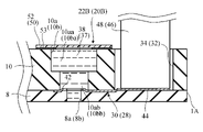
- the through hole 10a of the uppermost plate 10 has a large diameter portion 10aa at the upper portion and a small diameter portion 10ab at the lower portion. Both the large diameter portion 10aa and the small diameter portion 10ab are cylindrical, but the diameter of the large diameter portion 10aa is larger than the diameter of the small diameter portion 10ab. The diameter of the small diameter portion 10ab is larger than the diameter of the through hole 8a directly below the through hole 10a.
- the large-diameter portion 10aa is an opening of the second outlet hole 22B, and is opened on the upper surface of the particle analysis device 1. Therefore, the opening 10aa of the second outlet hole 22B has a larger area than the other portion of the second outlet hole 22B.
- the through hole 10b of the plate 10 has a large diameter portion 10ba at the upper portion and a small diameter portion 10bb at the lower portion. Both the large diameter portion 10ba and the small diameter portion 10bb are cylindrical, but the diameter of the large diameter portion 10ba is larger than the diameter of the small diameter portion 10bb. The diameter of the small diameter portion 10bb is larger than the diameter of the through hole 8b directly below the through hole 10b.
- the large-diameter portion 10ba is an opening of the first outlet hole 20B, and is opened on the upper surface of the particle analysis device 1. Therefore, the opening 10ba of the first outlet hole 20B has a larger area than the other portion of the first outlet hole 20B.
- the through holes 10c and 10d of the plate 10 have a cylindrical shape having a uniform diameter.
- the through holes 10c and 10d have the same diameter as the through holes 8a, 8b, 8c and 8d of the plate 8.
- the through hole 10c is an opening of the first inlet hole 20A, and is opened on the upper surface of the particle analysis device 1.
- the through hole 10d is an opening of the second inlet hole 22A, and is opened on the upper surface of the particle analysis device 1.
- the chip 24 is made of a brittle material
- the plate 6 into which the chip 24 is fitted is preferably formed of the above elastic material so that the liquid in the connection hole 26 of the chip 24 does not leak, and the chip 24 is tightened in the recess 6h of the plate 6. It is preferable to have dimensions (horizontal dimensions) suitable for fitting. Further, the depth of the recess 6h is preferably the same as or slightly larger than the height of the chip 24 so that no gap is generated between the lower surface of the chip 24 and the upper surface of the plate 4.
- the electrodes 28 and 30 are made of a material having high conductivity.
- the electrodes 28 and 30 can be formed of silver silver chloride (Ag / AgCl), platinum, and gold.
- the electrodes 28, 30 may be formed from a material containing any or all of these metals and an elastomer.
- each of the electrodes 28 and 30 formed on the plate 8 is a flat thin plate and is sandwiched between the two plates 8 and 10. As shown in FIG. 6, each of the electrodes 28 and 30 has an annular portion 42 formed around the through hole 8b or 8a (a part of the hole 20B or the hole 22B) of the plate 8 and an annular portion 42. It has a connected rectangular extension 44. The width of the extension portion 44 is smaller than the outer diameter of the ring portion 42.
- the annular portion 42 has a through hole having substantially the same diameter as the through holes 8a and 8b.
- the annular portion 42 is formed substantially concentrically with the through hole 8a or 8b of the plate 8, and substantially concentrically overlaps with the through hole 10a or 10b of the plate 10 directly above.
- the end of the extension 44 on the opposite side of the annulus 42 overlaps the electrode rod insertion hole 32 or 34 of the plate 10 directly above.
- the first electrode rod 46 inserted into the first electrode rod insertion hole 32 is brought into contact with the annular portion 42 of the first electrode 28, and the second electrode rod insertion hole 34 is brought into contact with the ring portion 42.
- the second electrode rod 48 inserted into the second electrode 30 is brought into contact with the annular portion 42 of the second electrode 30.
- the electrode rods 46 and 48 are connected to the DC power supply 35 and the ammeter 36 (see FIG. 2).
- the first outlet hole 20B has a through hole 10b above the first electrode 28 and a through hole 8b below the first electrode 28.
- the small diameter portion 10bb of the through hole 10b has a larger diameter and thus an area than the through hole 8b.
- the outer diameter of the annular portion 42 of the first electrode 28 is larger than the diameter of the small diameter portion 10bb of the through hole 10b directly above.
- the second outlet hole 22B has a through hole 10a above the second electrode 30 and a through hole 8a below the second electrode 30.
- the small diameter portion 10ab of the through hole 10a has a larger diameter and thus an area than the through hole 8a.
- the outer diameter of the annular portion 42 of the second electrode 30 is larger than the diameter of the small diameter portion 10ab of the through hole 10a directly above.
- the annular portion 42 of each electrode overlaps the through hole 10b or 10a having an opening area larger than that of the through holes 8b and 8a. Therefore, a large contact area between the liquid injected into the pores and the electrode is secured, and it is possible to improve the certainty of particle analysis.
- the second electrode 30 is in contact with the second liquid 38 inside the second outlet hole 22B (through holes 10a, 8a) in a large area, and the first electrode 28 is in contact with the second. It comes into contact with the first liquid 37 inside the outlet hole 20B (through holes 10b, 8b) of No. 1 in a large area.
- the outer diameter of the annulus 42 is larger than the diameters of the small diameter portions 10bb and 10ab directly above, even if the position of the annulus 42 deviates slightly from the desired position (that is, the position of the annulus 42). Even if the accuracy of the ring portion 42 is inaccurate), the annular portion 42 overlaps the small diameter portions 10bb and 10ab with high certainty. Therefore, in the plurality of particle analysis devices 1, the contact area between the liquid injected into the pores and the electrode is constant, and it is possible to improve the certainty of particle analysis.
- the particle analysis device 1 further has a first lid 50 and a second lid 52.
- the first lid 50 is arranged in the opening 10ba of the first outlet hole 20B and closes the opening 10ba.
- the second lid 52 is arranged in the opening 10aa of the second outlet hole 22B and closes the opening.
- the lids 50 and 52 are formed of a membrane that allows air to pass through but does not allow liquid to pass through. Thus, "blocking" means impeding the flow of liquid through the pores, but allowing the passage of air.
- the lids 50 and 52 have an area larger than the openings 10ba and 10aa, and cover the entire openings 10ba and 10aa, respectively.
- the lids 50 and 52 are shown by virtual lines.
- a membrane that allows air to pass through but does not allow liquid to pass through is a porous membrane formed of a hydrophobic resin (for example, PTFE (polytetrafluoroethylene), PFA (perfluoroalkoxy alkane)).
- the diameter of the pores of the porous membrane is preferably in the range of 0.1 ⁇ m to 10 ⁇ m. If the diameter of the hole is smaller than 0.1 ⁇ m, the air flow is obstructed. If the diameter of the pores is larger than 10 ⁇ m, the liquid may permeate the membrane at high pressure.
- the lids 50 and 52 are bonded to the upper surface of the plate 10 with a ring-shaped double-sided adhesive tape 53, particularly around the openings 10ba and 10aa.
- the double-sided adhesive tape 53 facilitates the deployment of the lids 50 and 52 on the particle analyzer 1.
- the first liquid 37 can be supplied to the upper liquid space 20 through the first inlet hole 20A.
- a syringe or pipette can be used to supply the liquid.
- the air in the upper liquid space 20 is discharged through the first outlet hole 20B, and the first liquid 37 enters the upper liquid space 20 from the first inlet hole 20A.
- the opening 10ba of the first outlet hole 20B is provided with a first lid 50 formed of a membrane that allows air to pass through but does not allow liquid to pass through. Therefore, even if the energy for introducing the first liquid 37 into the upper liquid space 20 is too strong, the first liquid 37 is blocked by the first lid 50 and does not scatter to the outside. Since the first lid 50 allows the passage of air, it does not prevent the first liquid 37 from entering the upper liquid space 20 through the first inlet hole 20A.
- the second liquid 38 can be supplied to the lower liquid space 22 through the second inlet hole 22A.
- a syringe or pipette can be used to supply the liquid.
- the air that was in the lower liquid space 22 is discharged through the second outlet hole 22B, and the second liquid 38 enters the lower liquid space 22 from the second inlet hole 22A.
- the opening 10aa of the second outlet hole 22B is provided with a second lid 52 formed of a membrane that allows air to pass through but does not allow liquid to pass through. Therefore, even if the energy for introducing the second liquid 38 into the lower liquid space 22 is too strong, the second liquid 38 is blocked by the second lid 52 and does not scatter to the outside. Since the second lid 52 allows the passage of air, it does not prevent the second liquid 38 from entering the liquid space 22 below through the second inlet hole 22A.
- the liquid contains a virus or a bacterium, it is possible to prevent such a liquid from being ejected from the particle analyzer 1. Further, it is possible to prevent the first liquid and the second liquid leaking from the upper surface of the particle analysis device 1 from coming into contact with each other and deteriorating the accuracy of particle analysis.
- S-NTF8031J is a product provided with a double-sided adhesive tape 53.
- the plate 10 was formed from VMQ (silicone rubber) containing PDMS.
- the diameters of the lids 50 and 52 were 5.6 mm, and the inner diameter of the ring-shaped double-sided adhesive tape 53 was 3 mm.
- the diameters of the openings 10ba and 10aa were 4 mm.
- a micropipette Using a micropipette, pure water was supplied to the upper liquid space 20 through the first inlet hole 20A. Pure water was filled in the upper liquid space 20, and the air in the upper liquid space 20 was discharged through the first outlet hole 20B. The first lid 50 prevented pure water from coming out from the first outlet hole 20B.
- a micropipette was used to supply pure water to the lower liquid space 22 through the second inlet hole 22A. Pure water was filled in the lower liquid space 22, and the air in the lower liquid space 22 was discharged through the second outlet hole 22B. The second lid 52 prevented pure water from coming out from the second outlet hole 22B.
- FIG. 8 shows a particle analysis apparatus 60 according to a second embodiment of the present invention.
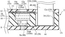
- the particle analysis device 60 has a particle analysis device 1 according to the first embodiment and a plate 12 joined to the upper surface of the particle analysis device 1. Therefore, the lids 50 and 52 are sandwiched between the plates 10 and 12 joined to each other and are firmly fixed to the device. That is, even if the lids 50 and 52 receive the pressure and energy of the liquid introduced into the device, the closure of the lids 50 and 52 from the device is reduced.
- the plate 12 has the same shape and size as the plate 10, and has through holes 12a, 12b, 12c, 12d, 12e, and 12f.
- the through hole 12a is concentrically aligned with the through hole 10a of the plate 10 and the second lid 52.
- the through hole 12a constitutes a second outlet hole 22B together with the through holes 10a, 8a, 6a, and 4a.
- the through hole 12a is an opening of the second outlet hole 22B, and is opened on the upper surface of the particle analysis device 60. Since the through hole 12a has a diameter smaller than the diameter of the second lid 52, the second lid 52 is supported in surface contact with the plate 12.
- the through hole 12b is concentrically aligned with the through hole 10b of the plate 10 and the first lid 50.
- the through hole 12b constitutes the first outlet hole 20B together with the through holes 10b and 8b.
- the through hole 12b is an opening of the first outlet hole 20B, and is opened on the upper surface of the particle analysis device 60. Since the through hole 12b has a diameter smaller than the diameter of the first lid 50, the first lid 50 is supported in surface contact with the plate 12.
- the through holes 12c and 12d have the same shape and size as the through holes 10c and 10d of the plate 10, and are concentrically aligned with the through holes 10c and 10d, respectively.
- the through hole 12c constitutes the first inlet hole 20A together with the through holes 10c and 8c.
- the through hole 12c is an opening of the first inlet hole 20A, and is opened on the upper surface of the particle analysis device 60.
- the through hole 12d constitutes the second inlet hole 22A together with the through holes 10d, 8d, 6d, and 4d.
- the through hole 12d is an opening of the second inlet hole 22A, and is opened on the upper surface of the particle analysis device 60.
- the through holes 12e and 12f have the same shape and size as the electrode rod insertion holes 34 and 32 of the plate 10, and are aligned with the electrode rod insertion holes 34 and 32, respectively. Therefore, the through hole 12f and the first electrode rod 46 inserted into the first electrode rod insertion hole 32 are brought into contact with the annular portion 42 of the first electrode 28, and the through hole 12e and the second electrode rod are brought into contact with each other. The second electrode rod 48 inserted into the insertion hole 34 is brought into contact with the annular portion 42 of the second electrode 30.
- the plate 12 can be joined to the plate 10 with an adhesive.
- the plates 10 and 12 are manufactured from silicone rubber or urethane rubber containing PDMS, the lids 50 and 52 are attached to the plate 10 with double-sided adhesive tape 53, and then the plates 12 are irradiated with vacuum ultraviolet rays or oxygen plasma. Can be joined to the plate 10.
- FIG. 11 is a cross-sectional view of a part of the particle analysis apparatus according to the third embodiment of the present invention.
- the lids 50 and 52 are adhered to the plate 10 by the double-sided adhesive tape 53.
- the double-sided adhesive tape 53 is not used, and the lids 50 and 52 come into direct contact with the plate 10. Even if the double-sided adhesive tape 53 is not used, the lids 50 and 52 are sandwiched between the plates 10 and 12 joined to each other and are firmly fixed to the device. Therefore, even if the lids 50 and 52 receive the pressure and energy of the liquid introduced into the device, the lids 50 and 52 are less likely to be separated from the device.
- the double-sided adhesive tape 53 since the double-sided adhesive tape 53 is not used, it is possible to prevent or reduce the undesired mixing of organic substances in the liquids 37 and 38.
- the product name "S-NTF8031” manufactured by Nitto Denko KK can be used as the lids 50 and 52.
- the "S-NTF8031” is the same as the above-mentioned "S-NTF803J" except that the double-sided adhesive tape 53 is not provided.
- the particle analysis apparatus shown in FIG. 11 prepares a plurality of plates 2,4,6,8,10,12 and prepares the plates 2,4,6,8,10,12 (for example, vacuum ultraviolet rays). Alternatively, it can be manufactured by a method having bonding (using oxygen plasma irradiation).
- preparing the plates 2, 4, 6, 8, 10, and 12 includes manufacturing the plate 12 as described below and at the same time integrally joining the lids 50 and 52 to the plate 12.
- FIG. 12 shows a step of manufacturing the plate 12 according to the fourth embodiment of the present invention.
- the mold 70 has an upper mold 70A and a lower mold 70B.
- the upper mold 70A is a flat plate and the lower mold 70B has a cavity 72 forming the plate 12. Pillars 74a, 74b, 74c, 74d, 74e, 74f for forming through holes 12a, 12b, 12c, 12d, 12e, 12f are arranged inside the cavity 72, respectively.
- the lids 50 and 52 are arranged in the cavity 72 of the lower mold 70B.
- the lids 50 and 52 are placed on the pillars 74b and 74a, respectively.
- the plate 12 is completed, and the plate 12 can be integrally joined to the first lid 50 and the second lid 52.
- the lids 50 and 52 are sandwiched between the plates 10 and 12 and firmly fixed to the device.
- the first lid 50 and the second lid 52 are easily joined to the plate 12, and the particle analysis device can be easily manufactured. Since the lids 50 and 52 are integrally joined to the plate 12, they are firmly fixed to the device.
- the fourth embodiment may be modified to form one plate corresponding to the plates 10 and 12 with a mold, and at the same time, the lids 50 and 52 may be embedded in the plate.
- FIG. 13 shows a process of manufacturing one plate corresponding to the plates 10 and 12 according to the fifth embodiment of the present invention.
- the mold 80 has an upper mold 80A and a lower mold 70B.
- the lower mold 70B is the same as the lower mold 70B of the fourth embodiment.
- the upper mold 80A has a cavity 82 forming a portion corresponding to the plate 10. Inside the cavity 82, columns 84a, 84b, 84c, 84d, 84e, 84f for forming through holes 10a, 10b, 10c, 10d and electrode rod insertion holes 34, 32, respectively, are arranged.
- the lids 50 and 52 are arranged in the cavity 72 of the lower mold 70B.
- the lids 50 and 52 are placed on the pillars 74b and 74a, respectively.
- one plate 14 corresponding to the plates 10 and 12 is completed, and the first lid 50 and the second lid 52 are integrated with the plate 14. Both sides of the first lid 50 and the second lid 52 are in contact with the plate 14.
- the first lid 50 and the second lid 52 are easily joined to the plate, and the particle analysis device can be easily manufactured. Since the lids 50 and 52 are integrally joined to the plate, they are firmly fixed to the device.
- the sealing property between the plates of the particle analysis device may be improved by using a compression mechanism (for example, a clamp mechanism, a screw, a pinch) that constantly compresses the particle analysis device in the vertical direction.
- a compression mechanism for example, a clamp mechanism, a screw, a pinch
- the number of plates included in the particle analyzer is not limited to the above embodiment.
- the upper liquid space 20 is formed by the grooves 6g formed in a single plate 6, but the upper liquid space 20 may be formed in a plurality of plates (for example, plates 6 and 8). good.
- the lower liquid space 22 is formed by the grooves 4g formed in a single plate 4, but the lower liquid space 22 may be formed in a plurality of plates (for example, plates 4 and 2). good.
- the chip 24 having the connection hole 26 is arranged inside a single plate 6, but the chip 24 may be arranged inside a plurality of plates (for example, plates 6 and 4).
- the extension 44 of the electrodes 28 and 30 is a rectangle having a uniform width.
- the extension portion 44 may have a wide portion and a narrow portion, or may be gradually decreased or gradually increased as the width of the extension portion 44 toward the side surface 1A.
- a second outlet hole having an opening that opens at the upper surface, extending from the upper surface to the lower liquid space, and discharging air from the lower liquid space.
- a first electrode that applies an electric potential to the first liquid in the upper liquid space
- a second electrode that applies an electric potential to the second liquid in the lower liquid space
- a first lid located in the opening of the first outlet hole and formed of a membrane that allows air to pass through but does not allow liquid to pass through.
- a second lid located in the opening of the second outlet hole and formed of a membrane that allows air to pass through but does not allow liquid to pass through.
- a particle analysis device characterized by this.
- Clause 2 The particle analysis apparatus according to Clause 1, wherein the first lid and the second lid are formed of a porous membrane made of a hydrophobic resin.
- the first lid and the second lid are firmly fixed to the device.
- Clause 5 With multiple boards laminated and joined, Clause 1 characterized in that the first lid and the second lid are embedded in one of the plates, and both sides of the first lid and the second lid are in contact with the plate. Or the particle analyzer according to 2.
- the first lid and the second lid are firmly fixed to the device.
- a method of manufacturing the particle analyzer according to clause 3 or 5. Preparing multiple boards and Has to join the plates
- Preparing the plate means arranging the first lid and the second lid in a mold for forming one of the plates, arranging the material of the plate in the mold, and arranging the material of the plate in the mold.
- a method for manufacturing a particle analysis apparatus which comprises curing the material of the plate and joining the plate to the first lid and the second lid.
- the first lid and the second lid are easily joined to the plate, and the particle analysis device can be easily manufactured.
- the first lid and the second lid are integrally joined to the plate so that they are firmly fixed to the device.
Landscapes
- Chemical & Material Sciences (AREA)
- Analytical Chemistry (AREA)
- General Health & Medical Sciences (AREA)
- Physics & Mathematics (AREA)
- Health & Medical Sciences (AREA)
- Life Sciences & Earth Sciences (AREA)
- Pathology (AREA)
- Biochemistry (AREA)
- Immunology (AREA)
- General Physics & Mathematics (AREA)
- Dispersion Chemistry (AREA)
- Electrochemistry (AREA)
- Chemical Kinetics & Catalysis (AREA)
- Sampling And Sample Adjustment (AREA)
- Electrostatic Separation (AREA)
Priority Applications (3)
| Application Number | Priority Date | Filing Date | Title |
|---|---|---|---|
| JP2022553542A JPWO2022070669A1 (https=) | 2020-09-29 | 2021-08-23 | |
| CN202180065156.6A CN116235036A (zh) | 2020-09-29 | 2021-08-23 | 颗粒分析装置及其制造方法 |
| US18/027,839 US20230332998A1 (en) | 2020-09-29 | 2021-08-23 | Particle analysis device and method for producing same |
Applications Claiming Priority (2)
| Application Number | Priority Date | Filing Date | Title |
|---|---|---|---|
| JP2020163035 | 2020-09-29 | ||
| JP2020-163035 | 2020-09-29 |
Publications (1)
| Publication Number | Publication Date |
|---|---|
| WO2022070669A1 true WO2022070669A1 (ja) | 2022-04-07 |
Family
ID=80949946
Family Applications (1)
| Application Number | Title | Priority Date | Filing Date |
|---|---|---|---|
| PCT/JP2021/030761 Ceased WO2022070669A1 (ja) | 2020-09-29 | 2021-08-23 | 粒子解析装置およびその製造方法 |
Country Status (4)
| Country | Link |
|---|---|
| US (1) | US20230332998A1 (https=) |
| JP (1) | JPWO2022070669A1 (https=) |
| CN (1) | CN116235036A (https=) |
| WO (1) | WO2022070669A1 (https=) |
Citations (11)
| Publication number | Priority date | Publication date | Assignee | Title |
|---|---|---|---|---|
| JPH11509094A (ja) * | 1995-06-29 | 1999-08-17 | アフィメトリックス,インコーポレイティド | 統合された核酸診断装置 |
| US20040238052A1 (en) * | 2001-06-07 | 2004-12-02 | Nanostream, Inc. | Microfluidic devices for methods development |
| JP2006149215A (ja) * | 2004-11-25 | 2006-06-15 | Asahi Kasei Corp | 核酸検出用カートリッジ及び核酸検出方法 |
| WO2013137209A1 (ja) | 2012-03-13 | 2013-09-19 | 株式会社 東芝 | 一粒子解析装置および解析方法 |
| JP2014174022A (ja) | 2013-03-08 | 2014-09-22 | Osaka Univ | 物質の識別方法 |
| JP2015036631A (ja) * | 2013-08-12 | 2015-02-23 | 株式会社東芝 | 半導体マイクロ分析チップ及びその製造方法 |
| JP2015513346A (ja) * | 2012-02-13 | 2015-05-11 | ニューモデックス モレキュラー インコーポレイテッドNeumodx Moleculer,Inc. | 核酸を処理及び検出するためのマイクロ流体カートリッジ |
| JP2016024013A (ja) * | 2014-07-18 | 2016-02-08 | 株式会社東芝 | 半導体マイクロ分析チップ |
| JP2017156168A (ja) | 2016-02-29 | 2017-09-07 | 国立大学法人大阪大学 | エクソソームの形状分布の解析装置、がん検査装置、エクソソームの形状分布の解析方法、及びがん検査方法 |
| JP2019516951A (ja) * | 2016-03-21 | 2019-06-20 | ツー ポア ガイズ インコーポレイテッド | ナノポアセンシングのための絶縁体−膜−絶縁体デバイスのウェハスケールアセンブリ |
| WO2021038977A1 (ja) * | 2019-08-28 | 2021-03-04 | Nok株式会社 | 粒子解析装置 |
-
2021
- 2021-08-23 JP JP2022553542A patent/JPWO2022070669A1/ja not_active Withdrawn
- 2021-08-23 CN CN202180065156.6A patent/CN116235036A/zh not_active Withdrawn
- 2021-08-23 WO PCT/JP2021/030761 patent/WO2022070669A1/ja not_active Ceased
- 2021-08-23 US US18/027,839 patent/US20230332998A1/en not_active Abandoned
Patent Citations (12)
| Publication number | Priority date | Publication date | Assignee | Title |
|---|---|---|---|---|
| JPH11509094A (ja) * | 1995-06-29 | 1999-08-17 | アフィメトリックス,インコーポレイティド | 統合された核酸診断装置 |
| US20040238052A1 (en) * | 2001-06-07 | 2004-12-02 | Nanostream, Inc. | Microfluidic devices for methods development |
| JP2006149215A (ja) * | 2004-11-25 | 2006-06-15 | Asahi Kasei Corp | 核酸検出用カートリッジ及び核酸検出方法 |
| JP2015513346A (ja) * | 2012-02-13 | 2015-05-11 | ニューモデックス モレキュラー インコーポレイテッドNeumodx Moleculer,Inc. | 核酸を処理及び検出するためのマイクロ流体カートリッジ |
| WO2013137209A1 (ja) | 2012-03-13 | 2013-09-19 | 株式会社 東芝 | 一粒子解析装置および解析方法 |
| WO2013136430A1 (ja) | 2012-03-13 | 2013-09-19 | 株式会社 東芝 | 一粒子解析装置および解析方法 |
| JP2014174022A (ja) | 2013-03-08 | 2014-09-22 | Osaka Univ | 物質の識別方法 |
| JP2015036631A (ja) * | 2013-08-12 | 2015-02-23 | 株式会社東芝 | 半導体マイクロ分析チップ及びその製造方法 |
| JP2016024013A (ja) * | 2014-07-18 | 2016-02-08 | 株式会社東芝 | 半導体マイクロ分析チップ |
| JP2017156168A (ja) | 2016-02-29 | 2017-09-07 | 国立大学法人大阪大学 | エクソソームの形状分布の解析装置、がん検査装置、エクソソームの形状分布の解析方法、及びがん検査方法 |
| JP2019516951A (ja) * | 2016-03-21 | 2019-06-20 | ツー ポア ガイズ インコーポレイテッド | ナノポアセンシングのための絶縁体−膜−絶縁体デバイスのウェハスケールアセンブリ |
| WO2021038977A1 (ja) * | 2019-08-28 | 2021-03-04 | Nok株式会社 | 粒子解析装置 |
Also Published As
| Publication number | Publication date |
|---|---|
| US20230332998A1 (en) | 2023-10-19 |
| CN116235036A (zh) | 2023-06-06 |
| JPWO2022070669A1 (https=) | 2022-04-07 |
Similar Documents
| Publication | Publication Date | Title |
|---|---|---|
| JP4213160B2 (ja) | 膜タンパク質分析用平面脂質二重膜の形成方法とその装置 | |
| CN101971013B (zh) | 人工脂质膜形成方法和人工脂质膜形成装置 | |
| JP6205055B2 (ja) | マイクロ流体チップ | |
| ES2881221T3 (es) | Chip microfluídico, método de fabricación del mismo y dispositivo de análisis que usa el mismo | |
| CN102077085A (zh) | 利用毛细管电泳法的分析装置 | |
| KR20150039051A (ko) | 혈액으로부터 혈장 또는 혈청을 분리하는 혈액 필터 장치 및 그의 용도 | |
| JP2013156063A (ja) | 液体試薬内蔵型マイクロチップおよびその使用方法、ならびに包材入り液体試薬内蔵型マイクロチップ | |
| JP4470999B2 (ja) | 細胞電気生理センサ | |
| JP2017227649A (ja) | マイクロ流体チップ | |
| WO2022070669A1 (ja) | 粒子解析装置およびその製造方法 | |
| CN110358676B (zh) | 数字pcr成像法检测中应用的微液滴取样装置 | |
| CN102553440A (zh) | 液体过滤装置及其过滤方法 | |
| KR102103950B1 (ko) | 유체 분석 카트리지 | |
| WO2022186047A1 (ja) | 粒子解析装置 | |
| WO2021038977A1 (ja) | 粒子解析装置 | |
| US20230077021A1 (en) | Particle analysis device | |
| US20230074523A1 (en) | Particle analysis device | |
| JP2019179033A (ja) | マイクロ流体チップシステム、および、流体混合物内の複数の成分を明らかにする方法 | |
| JP4425891B2 (ja) | 細胞電気生理センサおよびその製造方法 | |
| WO2020095849A1 (ja) | 細胞培養チップ及びその製造方法 | |
| JP2021131239A (ja) | 粒子解析装置 | |
| US11453904B2 (en) | Evaluation method for permeability of porous membrane, cell evaluation method, and drug evaluation method | |
| JP5011961B2 (ja) | 細胞電気生理センサおよびその製造方法 | |
| CN115916373A (zh) | 用于分选颗粒的微流控系统和方法 | |
| JP5951219B2 (ja) | 液体試薬内蔵型マイクロチップ |
Legal Events
| Date | Code | Title | Description |
|---|---|---|---|
| 121 | Ep: the epo has been informed by wipo that ep was designated in this application |
Ref document number: 21874972 Country of ref document: EP Kind code of ref document: A1 |
|
| ENP | Entry into the national phase |
Ref document number: 2022553542 Country of ref document: JP Kind code of ref document: A |
|
| NENP | Non-entry into the national phase |
Ref country code: DE |
|
| ENP | Entry into the national phase |
Ref document number: 2021874972 Country of ref document: EP Effective date: 20230502 |
|
| 122 | Ep: pct application non-entry in european phase |
Ref document number: 21874972 Country of ref document: EP Kind code of ref document: A1 |