WO2022070537A1 - ステータアッシー、ブラシレスモータ、および、ステータアッシーの製造方法 - Google Patents
ステータアッシー、ブラシレスモータ、および、ステータアッシーの製造方法 Download PDFInfo
- Publication number
- WO2022070537A1 WO2022070537A1 PCT/JP2021/024718 JP2021024718W WO2022070537A1 WO 2022070537 A1 WO2022070537 A1 WO 2022070537A1 JP 2021024718 W JP2021024718 W JP 2021024718W WO 2022070537 A1 WO2022070537 A1 WO 2022070537A1
- Authority
- WO
- WIPO (PCT)
- Prior art keywords
- stator
- housing member
- space
- housing
- insulating resin
- Prior art date
- Legal status (The legal status is an assumption and is not a legal conclusion. Google has not performed a legal analysis and makes no representation as to the accuracy of the status listed.)
- Ceased
Links
Images




Classifications
-
- H—ELECTRICITY
- H02—GENERATION; CONVERSION OR DISTRIBUTION OF ELECTRIC POWER
- H02K—DYNAMO-ELECTRIC MACHINES
- H02K5/00—Casings; Enclosures; Supports
- H02K5/04—Casings or enclosures characterised by the shape, form or construction thereof
- H02K5/08—Insulating casings
-
- H—ELECTRICITY
- H02—GENERATION; CONVERSION OR DISTRIBUTION OF ELECTRIC POWER
- H02K—DYNAMO-ELECTRIC MACHINES
- H02K1/00—Details of the magnetic circuit
- H02K1/06—Details of the magnetic circuit characterised by the shape, form or construction
- H02K1/12—Stationary parts of the magnetic circuit
- H02K1/18—Means for mounting or fastening magnetic stationary parts on to, or to, the stator structures
- H02K1/185—Means for mounting or fastening magnetic stationary parts on to, or to, the stator structures to outer stators
-
- H—ELECTRICITY
- H02—GENERATION; CONVERSION OR DISTRIBUTION OF ELECTRIC POWER
- H02K—DYNAMO-ELECTRIC MACHINES
- H02K1/00—Details of the magnetic circuit
- H02K1/06—Details of the magnetic circuit characterised by the shape, form or construction
- H02K1/12—Stationary parts of the magnetic circuit
-
- H—ELECTRICITY
- H02—GENERATION; CONVERSION OR DISTRIBUTION OF ELECTRIC POWER
- H02K—DYNAMO-ELECTRIC MACHINES
- H02K15/00—Processes or apparatus specially adapted for manufacturing, assembling, maintaining or repairing of dynamo-electric machines
- H02K15/12—Impregnating, moulding insulation, heating or drying of windings, stators, rotors or machines
-
- H—ELECTRICITY
- H02—GENERATION; CONVERSION OR DISTRIBUTION OF ELECTRIC POWER
- H02K—DYNAMO-ELECTRIC MACHINES
- H02K3/00—Details of windings
- H02K3/46—Fastening of windings on the stator or rotor structure
- H02K3/52—Fastening salient pole windings or connections thereto
- H02K3/521—Fastening salient pole windings or connections thereto applicable to stators only
- H02K3/522—Fastening salient pole windings or connections thereto applicable to stators only for generally annular cores with salient poles
-
- H—ELECTRICITY
- H02—GENERATION; CONVERSION OR DISTRIBUTION OF ELECTRIC POWER
- H02K—DYNAMO-ELECTRIC MACHINES
- H02K5/00—Casings; Enclosures; Supports
- H02K5/04—Casings or enclosures characterised by the shape, form or construction thereof
- H02K5/16—Means for supporting bearings, e.g. insulating supports or means for fitting bearings in the bearing-shields
- H02K5/167—Means for supporting bearings, e.g. insulating supports or means for fitting bearings in the bearing-shields using sliding-contact or spherical cap bearings
- H02K5/1675—Means for supporting bearings, e.g. insulating supports or means for fitting bearings in the bearing-shields using sliding-contact or spherical cap bearings radially supporting the rotary shaft at only one end of the rotor
Definitions
- the present invention relates to the structure of a stator assembly of a brushless motor.
- Patent Document 1 describes an inner rotor type brushless motor having a single-axis structure.
- the brushless motor described in Patent Document 1 includes a rotor, a stator, a holding plate, and a cover member.
- a holding plate is arranged on one end side of the rotor shaft, and one end of the rotor shaft abuts on the holding plate.
- the stator is arranged on the outer peripheral side of the rotor. The stator is fixed to the holding plate.
- the cover member has a cylindrical shape with one end open and is arranged so as to cover the stator and the rotor.
- the holding plate is fixed to the cover member so as to cover the opening of the cover member.
- the present invention is to provide a brushless motor having excellent quietness.
- the stator assembly of the present invention includes a stator, a housing having a space in which the stator is arranged, and an insulating resin arranged in the space.
- the housing and the stator are fixed by an insulating resin.
- the housing and the stator are fixed by an insulating resin to form an integrated structure.
- excitation vibration and structure resonance are suppressed.
- FIG. 1 is an external perspective view of the brushless motor 10 according to the first embodiment of the present invention.
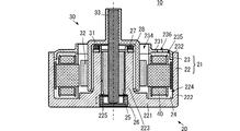
- FIG. 2 is a side sectional view showing the configuration of the brushless motor 10 according to the first embodiment of the present invention.
- FIG. 3 is a side sectional view showing the configuration of the stator assembly 20 according to the first embodiment of the present invention.
- FIG. 4A is a diagram showing a frequency characteristic of a vibration level
- FIG. 4B is a diagram showing a time characteristic of a motor temperature rise amount.
- FIG. 5 is a flowchart showing an example of a method for manufacturing a stator assembly according to an embodiment of the present invention.
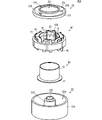
- FIG. 6 is a side sectional view showing the configuration of the stator assembly 20A according to the second embodiment of the present invention.
- FIG. 7 is an exploded perspective view of the stator assembly 20A according to the second embodiment of the present invention.
- FIG. 8 is a perspective view showing another shape of the filling auxiliary member.
- FIG. 1 is an external perspective view of the brushless motor 10 according to the first embodiment of the present invention.
- FIG. 2 is a side sectional view showing the configuration of the brushless motor 10 according to the embodiment of the present invention.
- FIG. 3 is a side sectional view showing the configuration of the stator assembly 20 according to the embodiment of the present invention.
- the brushless motor 10 includes a stator assembly 20 and a rotor 30.
- the specific structure of the stator assembly 20 will be described later.
- the rotor 30 includes a rotor yoke 31, a magnet 32, and a shaft 33.
- the description of the specific structure of the rotor 30 will be omitted.
- the stator assembly 20 has an opening 234.
- the rotor 30 is inserted into the stator assembly 20 through the opening 234.
- the opening 234 overlaps with the central space 400 of the stator 40 as shown in FIG. 7.
- the rotor 30 is arranged inside the stator 40.
- the stator 40 is arranged on the outer peripheral side of the rotor 30.
- One end of the rotor 30 in the extending direction of the shaft 33 projects outward from the opening 234 side of the stator assembly 20.
- the other end of the rotor 30 in the extending direction of the shaft 33 is rotatably supported by the stator assembly 20.
- the rotation of the rotor 30 is controlled by controlling the signal given to the stator 40.
- the brushless motor 10 realizes an inner rotor type brushless motor having a uniaxial structure.
- stator assembly 20 includes a housing 21, an insulating resin 24, a shaft lid member 25, a bearing 26, a suction magnet 27, a yoke 28, and a stator 40.
- the housing 21 includes a first housing member 22 and a second housing member 23.
- the first housing member 22 and the second housing member 23 are made of a highly rigid material such as SUS.
- the first housing member 22 includes a main wall 221, a side wall 222, and an internal wall 223.
- the main wall 221 is circular in a plan view.
- the side wall 222 has a cylindrical shape, is formed along the outer peripheral end of the main wall 221 and extends in a direction orthogonal to the main surface of the main wall 221.
- the inner wall 223 has a cylindrical shape, is formed in the center of the main wall 221 and extends in a direction orthogonal to the main surface of the main wall 221.
- the inner wall 223 has a hollow portion 225 that opens on both sides of the cylinder.
- the main wall 231 has an opening in a region overlapping the hollow portion 225. Therefore, the hollow portion 225 also communicates with the outside of the first housing member 22 on the main wall 231 side.
- the first housing member 22 has a space 224 surrounded by the main wall 221, the side wall 222, and the inner wall 223.
- the space 224 is annular in a plan view and opens on the side opposite to the main wall 221 side.
- the second housing member 23 includes a main wall 231 and a side wall 232.
- the main wall 231 is circular in a plan view.
- the side wall 232 has a cylindrical shape in a plan view.
- the side wall 232 has a cylindrical shape, is formed along the outer peripheral end of the main wall 231 and extends in a direction orthogonal to the main surface of the main wall 231.
- the second housing member 23 has a space 235 surrounded by the main wall 231 and the side wall 232.
- the space 235 is circular in a plan view and opens on the side opposite to the main wall 231 side.
- the main wall 231 has an opening 234 in the center that penetrates the main wall 231 in the thickness direction.
- the opening 234 communicates with the space 235.
- the opening 234 is circular in plan view.
- the outer shape of the opening 234 is similar to the outer shape of the rotor 30 in a plan view (the outer shape seen from one end or the other end side of the shaft 33).
- the area of the opening 234 is an area into which the rotor 30 can be inserted, and is, for example, about the plane area of the central space 400 of the stator 40.
- the main wall 231 has a plurality of holes 236.
- the plurality of holes 236 penetrate the main wall 231 in the thickness direction and communicate with the space 235.
- the plurality of holes 236 are arranged along the outer circumference of the opening 234.
- the first housing member 22 and the second housing member 23 are assembled to each other. More specifically, in the first housing member 22, the opening of the space 235 is the opening of the space 235 in the second housing member 23 so that the opening of the space 224 faces the second housing member 23 side. Arranged to face the side. Then, the second housing member 23 is fitted into the first housing member 22 so that the outer wall of the side wall 232 abuts on the inner wall surface 2221 of the side wall 222 of the first housing member 22.
- the housing 21 has an internal space.
- the internal space of the housing 21 communicates with the outside of the second housing member 23 side by the above-mentioned opening 234 and the plurality of holes 236.
- the shaft lid member 25 is disk-shaped and has a recess recessed from the main surface.
- the shaft lid member 25 is arranged near the end of the hollow portion 225 on the main wall 221 side.
- the bearing 26 has a cylindrical shape, is arranged in the hollow portion 225, and is fixed to the wall on the hollow portion 225 side of the inner wall 223.
- the suction magnet 27 has an annular shape.
- the attraction magnet 27 is arranged at the tip of the inner wall 223, in other words, at the end of the inner wall 223 opposite to the connection end to the main wall 221.
- the yoke 28 has an annular shape.
- the shape of the yoke 28 is substantially the same as the shape of the suction magnet 27.
- the yoke 28 is arranged near the tip of the inner wall 223 and is arranged on the main wall 221 side of the suction magnet 27.
- the stator 40 includes a plurality of stator cores 41, an insulator 42, and a plurality of coil conductors 43.
- the stator 40 is annular and has a central space 400.
- the plurality of stator cores 41 are arranged so as to be spaced apart from each other along the circumferential direction of the annular shape.
- the plurality of coil conductors 43 are wound around the plurality of stator cores 41 with the insulator 42 interposed therebetween. More specifically, the plurality of coil conductors 43 are wound around the stator core 41 about a direction extending outward from the center of the annular shape of the stator 40.
- the outer shape of the stator 40 in a plan view has substantially the same shape as the inner wall surface 2221 of the side wall 222 of the first housing member 22, and is smaller than the inner wall surface 2221.
- the outer shape of the central space in which the stator 40 is viewed in a plan view in other words, the shape of the inner end of the stator 40 is substantially the same as the outer shape of the rotor 30 described later, and is larger than the outer shape of the rotor 30.
- the stator 40 is arranged in the internal space of the housing 21. More specifically, the stator 40 is arranged so as to be accommodated in the space 224 of the first housing member 22 and the space 235 of the second housing member 23. At this time, the center of the stator 40 and the center of the internal space of the housing 21 substantially coincide with each other in a plan view. Further, the outer peripheral end of the stator 40 does not come into contact with the inner wall surface 2221 of the side wall 222 of the first housing member 22, but is in close proximity to the inner wall surface 2221.
- the positioning of the stator 40 with respect to the first housing member 22 is realized, for example, by abutting the leg member formed on the stator 40 on the inner surface of the main wall 221 of the first housing member 22.
- the insulating resin 24 has an annular shape and is arranged in the internal space of the housing 21. More specifically, the insulating resin 24 covers substantially the entire stator 40. Further, the insulating resin 24 comes into contact with substantially the entire surface of the inner wall surface 2211 of the main wall 221 of the first housing member 22 and substantially the entire surface of the inner wall surface 2221 of the side wall 222. Further, the insulating resin 24 comes into contact with substantially the entire surface of the inner wall surface 2311 of the main wall 231 of the second housing member 23 and substantially the entire surface of the inner wall surface 2321 of the side wall 232. Further, the cylindrical space formed in the center of the insulating resin 24 has a shape and size that can accommodate the rotor 30.
- stator 40 and the housing 21 are fixed by the insulating resin 24.
- first housing member 22 and the second housing member 23 are fixed by the insulating resin 24.
- the structure including the stator 40, the insulating resin 24, the first housing member 22, and the second housing member 23 is integrally formed. As a result, the excitation vibration and the structure resonance generated in the stator assembly 20 when the rotation of the rotor 30 is controlled are suppressed.
- FIG. 4A shows the frequency characteristics of the vibration level.
- the comparative configuration in FIG. 4A is a configuration in which the housing 21 is not filled with the insulating resin 24 and the structure in which the stator 40 is integrated with the housing 21 is not adopted. As shown in FIG. 4A, by using the configuration of this embodiment, the vibration level can be suppressed over a wide frequency band.
- first housing member 22 and the second housing member 23 are not fixed by screws, screws, or the like. Therefore, the positional deviation between the first housing member 22 and the second housing member 23 caused by screwing or screwing does not occur, and the generation of undesired vibration due to this positional deviation can be suppressed. Further, the first housing member 22 and the second housing member 23 do not require a portion for installing screws, screws, or the like. Therefore, the housing 21 can be made smaller than the structure using screws and screws while maintaining the shape of the stator 40.
- the material of the insulating resin 24 is made into a material having a higher thermal conductivity than air.
- the heat generated in the stator 40 is efficiently propagated to the housing 21 via the insulating resin 24. Therefore, the heat dissipation efficiency of the stator assembly 20 is improved.
- the insulating resin 24 covering the stator 40 is in surface contact with the first housing member 22 and the second housing member 23. As a result, the thermal conductivity to the first housing member 22 and the second housing member 23, that is, the housing 21, is further improved, and the heat dissipation efficiency of the stator assembly 20 is further improved.
- the insulating resin 24 comes into contact with substantially the entire surface of the inner wall surface 2211, the entire surface of the inner wall surface 2221, the substantially entire surface of the inner wall surface 2311, and the substantially entire surface of the inner wall surface 2321.
- the thermal conductivity to the first housing member 22 and the second housing member 23, that is, the housing 21, is further improved, and the heat dissipation efficiency of the stator assembly 20 is further improved.
- FIG. 4B shows the time characteristics of the amount of motor temperature rise.
- the comparative configuration in FIG. 4B is such that the housing 21 is not filled with the insulating resin 24.
- FIG. 4B by using the configuration of the present embodiment, it is possible to suppress the temperature rise of the motor during the transient operation and lower the temperature of the motor during the steady operation.
- FIG. 5 is a flowchart showing an example of a method for manufacturing the stator assembly 20 according to the embodiment of the present invention.
- the stator 40 is arranged in the space 224 of the first housing member 22 (S11).
- the second housing member 23 is mounted on the first housing member 22 (S12). More specifically, it corresponds to the space 224 of the first housing member 22 (corresponding to the "first space” of the present invention) and the space 235 of the second housing member 23 (corresponding to the "second space” of the present invention).
- the second housing member 23 is attached to the first housing member 22 so that the second housing member 23 communicates with the first housing member 22.
- the internal space of the housing 21 is filled with the insulating resin 24 (S13). Specifically, the insulating resin 24 flows into the housing 21 from the plurality of holes 236 formed in the second housing member 23 and is filled. At this time, a mold or the like is inserted into the area where the rotor 30 is arranged later. As a result, the insulating resin 24 does not enter the region where the rotor 30 is arranged. Next, the insulating resin 24 is cured (S14). The inserted mold may be removed after the insulating resin 24 is cured, for example.
- stator assembly 20 can be easily manufactured.
- FIG. 6 is a side sectional view showing the configuration of the stator assembly 20A according to the second embodiment of the present invention.
- FIG. 7 is an exploded perspective view of the stator assembly 20A according to the second embodiment of the present invention.
- the insulating resin 24 is omitted.
- FIG. 7 is a diagram of a state before the insulating resin 24 is filled and cured.
- stator assembly 20A of the brushless motor according to the second embodiment is different from the stator assembly 20 according to the first embodiment in that it includes a filling auxiliary member 50.
- Other configurations of the stator assembly 20A are the same as those of the stator assembly 20, and the description of the same parts will be omitted.
- the stator assembly 20A includes a filling auxiliary member 50.
- the filling auxiliary member 50 has a cylindrical shape and is made of a non-magnetic insulating resin.
- the filling auxiliary member 50 corresponds to the "auxiliary member" of the present invention.
- the filling auxiliary member 50 includes a cylindrical main body portion 51 and an annular bottom portion 52.
- the main body 51 and the bottom 52 are integrally molded, for example.
- the bottom portion 52 is arranged at one end of the main body portion 51 in the axial direction of the cylinder.
- the filling auxiliary member 50 is arranged so that the circumferential surface of the main body 51 is close to the inner peripheral end of the stator 40 and is along the inner peripheral end.
- the bottom portion 52 abuts on the main wall 221 of the first housing member 22, and the end portion of the main body portion 51 opposite to the bottom portion 52 side abuts on the main wall 231 of the second housing member 23.
- the stator 40 is arranged in the space surrounded by the filling auxiliary member 50, the main wall 221 of the first housing member 22, the side wall 222, and the main wall 231 of the second housing member 23.
- the insulating resin 24 is filled in the space surrounded by the filling auxiliary member 50, the main wall 221 of the first housing member 22, the side wall 222, and the main wall 231 of the second housing member 23.
- the filling auxiliary member 50 is provided with a ring-shaped fixing portion at the bottom, and the fixing portion is fixed to the main wall 221 of the first housing member 22 by an adhesive or the like. Will be done. As a result, the movement of the filling auxiliary member 50 when the insulating resin 24 is filled is suppressed. Therefore, the insulating resin 24 can be filled in the desired space.
- the insulating resin 24 can be reliably filled in a desired space without using the mold or the like shown in the first embodiment. Further, the rotor 30 can be inserted into the stator assembly 20 without waiting for the insulating resin 24 to cure, and the manufacturing time can be shortened.
- FIG. 8 is a perspective view showing another shape of the filling auxiliary member 50. Compared to the filling auxiliary member 50 shown in FIG. 7, the difference is that a plurality of protrusions 53, which are arranged at intervals along the circumferential surface of the main body 51, are provided.
- the stator 40 can be arranged so as to sandwich the plurality of protrusions 53 between the stator cores 41 of the stator 40. Thereby, for example, the amount of the insulating resin 24 can be reduced.
- Such a state means a state in which the housing and the stator are fixed in the present invention.
- the state in which the housing and the stator are joined and bonded so that the housing and the stator can be regarded as an integral body with respect to vibration is the state in which the housing and the stator are fixed in the present invention.
- the definition of "fixing" is the same for joining and adhering the first housing member 22 and the second housing member 23.
- the above-mentioned action and effect can be obtained more effectively.
Landscapes
- Engineering & Computer Science (AREA)
- Power Engineering (AREA)
- Manufacturing & Machinery (AREA)
- Motor Or Generator Frames (AREA)
- Iron Core Of Rotating Electric Machines (AREA)
- Manufacture Of Motors, Generators (AREA)
Abstract
ブラシレスモータ(10)は、ステータアッシー(20)とロータ(30)とを備える。ステータアッシー(20)は、ステータ(40)と、ステータ(40)が配置される空間を有する筐体(21)と、空間に配置された絶縁性樹脂(24)と、を備える。筐体(21)とステータ(40)とは、絶縁性樹脂(24)によって固定されている。また、筐体(21)は、第1筐体部材(22)と第2筐体部材(23)とを備える。第1筐体部材(22)と第2筐体部材(23)は、絶縁性樹脂(24)によって固定される。
Description
本発明は、ブラシレスモータのステータアッシーの構造に関する。
特許文献1には、インナーロータ型で片軸構造のブラシレスモータが記載されている。
特許文献1に記載のブラシレスモータは、ロータ、ステータ、保持板、および、カバー部材を備える。ロータの軸の一方端側には、保持板が配置され、ロータの軸の一方端は、保持板に当接する。ステータは、ロータの外周側に配置される。ステータは、保持板に固定される。
カバー部材は、一方端が開口する円筒形であり、ステータおよびロータを覆うように配置される。保持板は、カバー部材の開口を覆うように、カバー部材に固定される。
しかしながら、特許文献1に示す構造では、ロータの回転によって生じる振動から、大きな音が発生してしまう。
したがって、本発明は、静音性に優れたブラシレスモータを提供することにある。
この発明のステータアッシーは、ステータと、ステータが配置される空間を有する筐体と、空間に配置された絶縁性樹脂と、を備える。筐体とステータとは、絶縁性樹脂によって固定されている。
この構成では、筐体とステータとが絶縁性樹脂によって固定され、一体化された構造体となる。これにより、励磁振動、および、構造体共振が抑制される。
この発明によれば、静音性に優れたブラシレスモータを実現できる。
[第1の実施形態]
本発明の第1の実施形態に係るブラシレスモータ、ステータアッシー、および、これらの製造方法について、図を参照して説明する。
本発明の第1の実施形態に係るブラシレスモータ、ステータアッシー、および、これらの製造方法について、図を参照して説明する。
図1は、本発明の第1の実施形態に係るブラシレスモータ10の外観斜視図である。図2は、本発明の実施形態に係るブラシレスモータ10の構成を示す側面断面図である。図3は、本発明の実施形態に係るステータアッシー20の構成を示す側面断面図である。
(ブラシレスモータ10の概略構成)
図1、図2に示すように、ブラシレスモータ10は、ステータアッシー20、および、ロータ30を備える。ステータアッシー20の具体的な構造は後述する。
図1、図2に示すように、ブラシレスモータ10は、ステータアッシー20、および、ロータ30を備える。ステータアッシー20の具体的な構造は後述する。
ロータ30は、図2に示すように、ロータヨーク31、磁石32、および、シャフト33を備える。ロータ30の具体的な構造の説明は省略する。
ステータアッシー20は、開口234を有する。ロータ30は、開口234から、ステータアッシー20の内部に挿入される。ブラシレスモータ10(ステータアッシー20)を平面視して、開口234は、図7に示すようにステータ40の中央空間400と重なっている。これにより、ロータ30は、ステータ40の内側に配置される。言い換えれば、ステータ40は、ロータ30の外周側に配置される。
ロータ30のシャフト33の延びる方向の一方端は、ステータアッシー20の開口234側から外部に突出している。ロータ30のシャフト33の延びる方向の他方端は、ステータアッシー20によって回転可能に支持されている。
この構成において、ステータ40に与える信号を制御することで、ロータ30の回転は、制御される。これにより、ブラシレスモータ10は、インナーロータ型で片軸構造のブラシレスモータを実現する。
(ステータアッシー20の具体的な構成)
図1、図2、図3に示すように、ステータアッシー20は、筐体21、絶縁性樹脂24、軸用蓋部材25、軸受け26、吸引磁石27、ヨーク28、および、ステータ40を備える。
図1、図2、図3に示すように、ステータアッシー20は、筐体21、絶縁性樹脂24、軸用蓋部材25、軸受け26、吸引磁石27、ヨーク28、および、ステータ40を備える。
筐体21は、第1筐体部材22および第2筐体部材23を備える。第1筐体部材22および第2筐体部材23は、SUS等の剛性の高い材料からなる。
第1筐体部材22は、主壁221、側壁222、および、内部壁223を備える。主壁221は、平面視して、円形である。側壁222は、円筒形であり、主壁221の外周端に沿って形成され、主壁221の主面に直交する方向に延びる形状である。
内部壁223は円筒形であり、主壁221の中央に形成され、主壁221の主面に直交する方向に延びる形状である。内部壁223は、円筒形の両側で開口する中空部225を有する。主壁231には、中空部225と重なる領域に開口を有する。したがって、中空部225は、第1筐体部材22における主壁231側の外部にも連通する。
主壁221、側壁222、および、内部壁223が上述の構成であることによって、第1筐体部材22は、主壁221、側壁222、および、内部壁223によって囲まれる空間224を有する。空間224は、平面視して環状であり、主壁221側と反対側で開口する。
第2筐体部材23は、主壁231と側壁232とを備える。主壁231は、平面視して円形である。側壁232は、平面視して円筒形である。側壁232は、円筒形であり、主壁231の外周端に沿って形成され、主壁231の主面に直交する方向に延びる形状である。これにより、第2筐体部材23は、主壁231と側壁232とによって囲まれる空間235を有する。空間235は、平面視において円形であり、主壁231側と反対側で開口する。
主壁231は、主壁231を厚み方向に貫通する開口234を、中央に有する。開口234は、空間235に連通する。開口234は、平面視して円形である。開口234の外形は、ロータ30を平面視した外形(シャフト33の一方端または他方端側から視た外形)に対して相似形である。開口234の面積は、ロータ30が挿入可能な面積であり、例えば、ステータ40の中央空間400の平面面積程度である。
また、主壁231は、複数の孔236を有する。複数の孔236は、主壁231を厚み方向に貫通し、空間235に連通する。複数の孔236は、開口234の外周に沿って配置される。
第1筐体部材22と第2筐体部材23とは、互いに組み付けられる。より具体的には、第1筐体部材22は、空間224の開口が第2筐体部材23側に向くように、第2筐体部材23は、空間235の開口が第1筐体部材22側に向くように、配置される。そして、第2筐体部材23は、側壁232の外壁が第1筐体部材22の側壁222の内壁面2221に当接するように、第1筐体部材22に嵌め込まれる。
これにより、筐体21は、内部空間を有する。筐体21の内部空間は、上述の開口234および複数の孔236によって、第2筐体部材23側の外部に連通する。
軸用蓋部材25は、円板形であり、一方主面から凹む凹部を有する。軸用蓋部材25は、中空部225における主壁221側の端部付近に配置される。
軸受け26は、円筒形であり、中空部225に配置され、内部壁223の中空部225側の壁に固定される。
吸引磁石27は、円環形である。吸引磁石27は、内部壁223の先端、言い換えれば、内部壁223における主壁221への接続端と反対側の端部に配置される。
ヨーク28は、円環形である。ヨーク28の形状は、吸引磁石27の形状と略同じである。ヨーク28は、内部壁223の先端付近に配置され、吸引磁石27の主壁221側に配置される。
図7に示すように、ステータ40は、複数のステータコア41、インシュレータ42、および、複数のコイル導体43を備える。ステータ40は、円環形であり、中央空間400を有する。複数のステータコア41は、円環形の周方向に沿って、互いに間隔を空けて配置される。複数のコイル導体43は、インシュレータ42を間に挟んで、複数のステータコア41に巻き付けられている。より具体的には、複数のコイル導体43は、ステータ40の円環形の中心から外方に延びる方向を軸としてステータコア41に対して、巻回される。
ステータ40を平面視した外形は、第1筐体部材22の側壁222の内壁面2221と略同じ形状で、且つ、内壁面2221よりも小さい。ステータ40を平面視した中央空間の外形、言い換えれば、ステータ40の内端の形状は、後述するロータ30の外形と略同じ形状で、且つ、ロータ30の外形よりも大きい。
ステータ40は、筐体21の内部空間に配置される。より具体的には、ステータ40は、第1筐体部材22の空間224および第2筐体部材23の空間235に収容されるように配置される。この際、平面視した状態において、ステータ40の中心と筐体21の内部空間の中心とは略一致する。また、ステータ40の外周端は、第1筐体部材22の側壁222の内壁面2221に接触せず、近接する。なお、ステータ40の第1筐体部材22に対する位置決めは、例えば、ステータ40に形成された脚部材を第1筐体部材22の主壁221の内面に当接することによって実現される。
絶縁性樹脂24は、円環形であり、筐体21の内部空間に配置される。より具体的には、絶縁性樹脂24は、ステータ40の略全体を覆う。また、絶縁性樹脂24は、第1筐体部材22の主壁221の内壁面2211の略全面、および、側壁222の内壁面2221の略全面に当接する。さらに、絶縁性樹脂24は、第2筐体部材23の主壁231の内壁面2311の略全面、および、側壁232の内壁面2321の略全面に当接する。また、絶縁性樹脂24の中央に形成された円柱形の空間は、ロータ30が収容可能な形状および大きさである。
この構成によって、ステータ40と筐体21とは、絶縁性樹脂24によって固定される。さらに、第1筐体部材22、および、第2筐体部材23は、絶縁性樹脂24によって固定される。これにより、ステータ40、絶縁性樹脂24、第1筐体部材22、および、第2筐体部材23からなる構造体が一体に形成される。この結果、ロータ30が回転制御されたときにステータアッシー20に生じる励磁振動、および、構造体共振が抑制される。
図4(A)は、振動レベルの周波数特性を示す。なお、図4(A)における比較構成は、筐体21に絶縁性樹脂24を充填せず、ステータ40を筐体21と一体化させた構造を採用しない構成である。図4(A)に示すように、本実施形態の構成を用いることで、広い周波数帯域に亘って、振動レベルを抑圧できる。
また、第1筐体部材22および第2筐体部材23が、ネジ、ビス等によって固定されていない。したがって、ネジ留め、ビス留めで生じる第1筐体部材22と第2筐体部材23との位置ズレは生じず、この位置ズレによる不所望な振動の発生を抑制できる。また、第1筐体部材22および第2筐体部材23にネジ、ビス等を設置する部分を必要としない。したがって、ステータ40の形状を維持したままで、ネジ、ビスを用いる構造よりも、筐体21を小型化できる。
また、絶縁性樹脂24の材料を、空気よりも熱伝導率の高い材料にする。これにより、ステータ40で発生した熱は、絶縁性樹脂24を介して、筐体21に効率的に伝搬される。したがって、ステータアッシー20の放熱効率は向上する。特に、本実施形態では、ステータ40を覆う絶縁性樹脂24は、第1筐体部材22および第2筐体部材23に面で接する。これにより、第1筐体部材22および第2筐体部材23、すなわち、筐体21への熱伝導性は、さらに向上し、ステータアッシー20の放熱効率は、さらに向上する。さらに、絶縁性樹脂24は、内壁面2211の略全面、内壁面2221の略全面、内壁面2311の略全面、および、内壁面2321の略全面に当接する。これにより、第1筐体部材22および第2筐体部材23、すなわち、筐体21への熱伝導性は、より一層向上し、ステータアッシー20の放熱効率は、より一層向上する。
図4(B)は、モータ温度上昇量の時間特性を示す。なお、図4(B)における比較構成は、筐体21に絶縁性樹脂24を充填しない構成である。図4(B)に示すように、本実施形態の構成を用いることで、過渡時におけるモータの温度上昇を抑制でき、定常運転時におけるモータの温度を低くできる。
(ステータアッシー20の製造方法)
上述の構成からなるステータアッシー20は、例えば、次に示す方法によって製造できる。図5は、本発明の実施形態に係るステータアッシー20の製造方法の一例を示すフローチャートである。
上述の構成からなるステータアッシー20は、例えば、次に示す方法によって製造できる。図5は、本発明の実施形態に係るステータアッシー20の製造方法の一例を示すフローチャートである。
図5に示すように、まず、第1筐体部材22の空間224にステータ40を配置する(S11)。次に、第1筐体部材22に第2筐体部材23を装着する(S12)。より具体的には、第1筐体部材22の空間224(本発明の「第1空間」に対応。)と、第2筐体部材23の空間235(本発明の「第2空間」に対応。)が連通するように、第1筐体部材22に第2筐体部材23を装着する。
次に、筐体21の内部空間に絶縁性樹脂24を充填する(S13)。具体的には、第2筐体部材23に形成された複数の孔236から、筐体21内に絶縁性樹脂24を流入し、充填する。この際、後にロータ30が配置される領域には、金型等を挿入する。これにより、ロータ30が配置される領域には、絶縁性樹脂24は、入り込まない。次に、絶縁性樹脂24を硬化する(S14)。なお、挿入した金型は、例えば、絶縁性樹脂24の硬化後に、取り外せばよい。
このような製造方法を用いることによって、ステータアッシー20は、容易に製造できる。
[第2の実施形態]
本発明の第2の実施形態に係るブラシレスモータ、ステータアッシー、および、これらの製造方法について、図を参照して説明する。
本発明の第2の実施形態に係るブラシレスモータ、ステータアッシー、および、これらの製造方法について、図を参照して説明する。
図6は、本発明の第2の実施形態に係るステータアッシー20Aの構成を示す側面断面図である。図7は、本発明の第2の実施形態に係るステータアッシー20Aの分解斜視図である。なお、図7では、絶縁性樹脂24を省略して記載している。言い換えれば、図7は、絶縁性樹脂24が充填、硬化される前の状態の図である。
図6、図7に示すように、第2の実施形態に係るブラシレスモータのステータアッシー20Aは、第1の実施形態に係るステータアッシー20に対して、充填用補助部材50を備える点で異なる。ステータアッシー20Aの他の構成は、ステータアッシー20と同様であり、同様の箇所の説明は省略する。
ステータアッシー20Aは、充填用補助部材50を備える。充填用補助部材50は、円筒形であり、非磁性の絶縁性樹脂を材料とする。充填用補助部材50が、本発明の「補助部材」に対応する。
充填用補助部材50は、円筒形の主体部51、円環形の底部52を備える。主体部51、底部52は、例えば、一体成形される。底部52は、主体部51における円筒形の軸方向の一方端に配置される。
充填用補助部材50は、主体部51の円周面がステータ40の内周端に近接し、この内周端に沿うように配置される。底部52は、第1筐体部材22の主壁221に当接し、主体部51における底部52側と反対側の端部は、第2筐体部材23の主壁231に当接する。これにより、ステータ40は、充填用補助部材50、第1筐体部材22の主壁221、側壁222、および、第2筐体部材23の主壁231によって囲まれた空間内に配置される。
絶縁性樹脂24は、この充填用補助部材50、第1筐体部材22の主壁221、側壁222、および、第2筐体部材23の主壁231によって囲まれた空間内に充填される。
なお、図7に示すように、充填用補助部材50は、底部に円環形の固定部を備えており、この固定部が、第1筐体部材22の主壁221に、接着材等によって固着される。これにより、絶縁性樹脂24が充填されるときの充填用補助部材50の移動が抑制される。したがって、所望の空間に絶縁性樹脂24を充填できる。
このような構成を用いることで、第1の実施形態に示した金型等を用いることなく、絶縁性樹脂24を、所望の空間により確実に充填できる。また、絶縁性樹脂24の硬化を待たずに、ステータアッシー20へのロータ30の挿入が可能になり、製造時間を短くできる。
図8は、充填用補助部材50の別形状を示す斜視図である。図7に示した充填用補助部材50に比して、主体部51の円周面に沿って間隔を空けて配置される、複数の突起部53が設けられている点が相違する。
複数の突起部53を備えることによって、当該複数の突起部53をステータ40のステータコア41間に挟み込むように、ステータ40を配置することが可能になる。これにより、例えば、絶縁性樹脂24の量を削減できる。
上述の各実施形態の構成では、ステータ40を囲む空間の全体に絶縁性樹脂24を充填する態様を示した。しかしながら、少なくともステータ40の底部が所定深さで絶縁性樹脂24に埋まる態様であれば、上述の作用効果を奏することが可能である。このような状態が、本発明における「筐体とステータとが固定された」状態を意味する。言い換えれば、振動に対して筐体とステータとが一体物とみなせるように、筐体とステータとが接合、接着された状態が、本発明における「筐体とステータとが固定された」状態を意味する。この「固定」の定義は、第1筐体部材22と第2筐体部材23との接合、接着についても同じである。
また、例えば、ステータ40を囲む空間の約70%以上に、絶縁性樹脂24が充填されていれば、上述の作用効果は、より効果的に得られる。
10:ブラシレスモータ
20、20A:ステータアッシー
21:筐体
22:第1筐体部材
23:第2筐体部材
24:絶縁性樹脂
25:軸用蓋部材
26:軸受け
27:吸引磁石
28:ヨーク
30:ロータ
31:ロータヨーク
32:磁石
33:シャフト
40:ステータ
41:複数のステータコア
42:インシュレータ
43:コイル導体
50:充填用補助部材
20、20A:ステータアッシー
21:筐体
22:第1筐体部材
23:第2筐体部材
24:絶縁性樹脂
25:軸用蓋部材
26:軸受け
27:吸引磁石
28:ヨーク
30:ロータ
31:ロータヨーク
32:磁石
33:シャフト
40:ステータ
41:複数のステータコア
42:インシュレータ
43:コイル導体
50:充填用補助部材
Claims (9)
- ステータと、
前記ステータが配置される空間を有する筐体と、
前記空間に配置された絶縁性樹脂と、
を備え、
前記筐体と前記ステータとは、前記絶縁性樹脂によって固定されている、
ステータアッシー。 - 前記筐体は、前記空間を内部に形成する第1筐体部材および第2筐体部材と、を備え、
前記第1筐体部材と前記第2筐体部材と前記ステータとが、前記絶縁性樹脂によって固定されている、
請求項1に記載のステータアッシー。 - 前記絶縁性樹脂は、前記第1筐体部材の内壁面、および、前記第2筐体部材の内壁面に、面で接している、
請求項2に記載のステータアッシー。 - 前記絶縁性樹脂は、空気よりも高い熱伝導率を有する、
請求項1乃至請求項3のいずれかに記載のステータアッシー。 - 前記ステータの内周端に沿って配置され、前記筐体とともに前記ステータおよび前記絶縁性樹脂を囲む補助部材を備える、
請求項1乃至請求項4のいずれかに記載のステータアッシー。 - 請求項1乃至請求項5のいずれかに記載のステータアッシーと、
前記ステータの内側に配置されたロータと、
を備えた、
ブラシレスモータ。 - 第1空間を有する第1筐体部材に、ステータを配置する工程と、
第2空間を有する第2筐体部材を、前記第2空間と前記第1空間とが連通して、前記ステータが配置される空間を形成するように、前記第1筐体部材に配置する工程と、
前記ステータ、前記第1筐体部材の前記第1空間を形成する内壁面、および、前記第2筐体部材の前記第2空間を形成する内壁面に当接するように、前記空間に絶縁性樹脂を流入する工程と、
前記絶縁性樹脂を硬化させる工程と、
を有する、ステータアッシーの製造方法。 - 前記ステータを配置する工程の前に、前記空間を形成するための補助部材を、前記第1筐体部材に装着する工程を、
さらに有する、請求項7に記載のステータアッシーの製造方法。 - 前記補助部材は、円筒形の主体部と、円環形の底部と、前記主体部の円周面に設けられた複数の突起部とを備え、一体成形されていることを特徴とする、請求項8に記載のステータアッシーの製造方法。
Priority Applications (3)
| Application Number | Priority Date | Filing Date | Title |
|---|---|---|---|
| CN202180050026.5A CN115885451B (zh) | 2020-10-01 | 2021-06-30 | 定子组件、无刷电动机以及定子组件的制造方法 |
| JP2022553475A JP7537508B2 (ja) | 2020-10-01 | 2021-06-30 | ステータアッシー、ブラシレスモータ、および、ステータアッシーの製造方法 |
| US18/161,369 US20230216366A1 (en) | 2020-10-01 | 2023-01-30 | Stator assy, brushless motor, and method for manufacturing stator assy |
Applications Claiming Priority (2)
| Application Number | Priority Date | Filing Date | Title |
|---|---|---|---|
| JP2020166696 | 2020-10-01 | ||
| JP2020-166696 | 2020-10-01 |
Related Child Applications (1)
| Application Number | Title | Priority Date | Filing Date |
|---|---|---|---|
| US18/161,369 Continuation US20230216366A1 (en) | 2020-10-01 | 2023-01-30 | Stator assy, brushless motor, and method for manufacturing stator assy |
Publications (1)
| Publication Number | Publication Date |
|---|---|
| WO2022070537A1 true WO2022070537A1 (ja) | 2022-04-07 |
Family
ID=80949859
Family Applications (1)
| Application Number | Title | Priority Date | Filing Date |
|---|---|---|---|
| PCT/JP2021/024718 Ceased WO2022070537A1 (ja) | 2020-10-01 | 2021-06-30 | ステータアッシー、ブラシレスモータ、および、ステータアッシーの製造方法 |
Country Status (4)
| Country | Link |
|---|---|
| US (1) | US20230216366A1 (ja) |
| JP (1) | JP7537508B2 (ja) |
| CN (1) | CN115885451B (ja) |
| WO (1) | WO2022070537A1 (ja) |
Families Citing this family (1)
| Publication number | Priority date | Publication date | Assignee | Title |
|---|---|---|---|---|
| DE102024127690A1 (de) * | 2024-09-25 | 2026-03-26 | Schaeffler Technologies AG & Co. KG | Verfahren zur Herstellung eines Stators |
Citations (4)
| Publication number | Priority date | Publication date | Assignee | Title |
|---|---|---|---|---|
| US20130272904A1 (en) * | 2012-03-29 | 2013-10-17 | Ebara Corporation | Canned motor and vacuum pump |
| JP2014087104A (ja) * | 2012-10-19 | 2014-05-12 | Nissan Motor Co Ltd | モーター構造 |
| JP2016197966A (ja) * | 2015-04-06 | 2016-11-24 | パナソニックIpマネジメント株式会社 | 固定子構成体、電動機、装置 |
| JP2017099075A (ja) * | 2015-11-19 | 2017-06-01 | 株式会社豊田自動織機 | 回転電機 |
Family Cites Families (2)
| Publication number | Priority date | Publication date | Assignee | Title |
|---|---|---|---|---|
| JP6430266B2 (ja) * | 2015-01-20 | 2018-11-28 | 愛三工業株式会社 | ステータ及び電動ポンプ |
| JP7234558B2 (ja) * | 2018-09-28 | 2023-03-08 | 日本電産株式会社 | ステータユニット、モータ、及び送風装置 |
-
2021
- 2021-06-30 CN CN202180050026.5A patent/CN115885451B/zh active Active
- 2021-06-30 JP JP2022553475A patent/JP7537508B2/ja active Active
- 2021-06-30 WO PCT/JP2021/024718 patent/WO2022070537A1/ja not_active Ceased
-
2023
- 2023-01-30 US US18/161,369 patent/US20230216366A1/en active Pending
Patent Citations (4)
| Publication number | Priority date | Publication date | Assignee | Title |
|---|---|---|---|---|
| US20130272904A1 (en) * | 2012-03-29 | 2013-10-17 | Ebara Corporation | Canned motor and vacuum pump |
| JP2014087104A (ja) * | 2012-10-19 | 2014-05-12 | Nissan Motor Co Ltd | モーター構造 |
| JP2016197966A (ja) * | 2015-04-06 | 2016-11-24 | パナソニックIpマネジメント株式会社 | 固定子構成体、電動機、装置 |
| JP2017099075A (ja) * | 2015-11-19 | 2017-06-01 | 株式会社豊田自動織機 | 回転電機 |
Also Published As
| Publication number | Publication date |
|---|---|
| US20230216366A1 (en) | 2023-07-06 |
| JPWO2022070537A1 (ja) | 2022-04-07 |
| JP7537508B2 (ja) | 2024-08-21 |
| CN115885451A (zh) | 2023-03-31 |
| CN115885451B (zh) | 2026-04-24 |
Similar Documents
| Publication | Publication Date | Title |
|---|---|---|
| JP6059275B2 (ja) | アウタロータ型モータ | |
| US10951097B2 (en) | Rotor, manufacturing method of the rotor, and motor | |
| JP3401640B2 (ja) | 送風機及びその製造方法 | |
| JP5775853B2 (ja) | モールドモータ | |
| US11101708B2 (en) | Rotor, motor, air conditioning apparatus, and manufacturing method of rotor | |
| US20030173851A1 (en) | Watertight brushless fan motor | |
| US20220166290A1 (en) | Motor, fan, air conditioner, and manufacturing method of motor | |
| JP3345365B2 (ja) | 小型モータ | |
| JP7400436B2 (ja) | モータ、および電動ポンプ | |
| US20220271595A1 (en) | Stator and motor | |
| WO2018037652A1 (ja) | コンシクエントポール型の回転子、電動機および空気調和機 | |
| US20230216366A1 (en) | Stator assy, brushless motor, and method for manufacturing stator assy | |
| JP3881353B2 (ja) | ステッピングモータ | |
| JP2017015002A (ja) | ポンプ装置 | |
| CN110402529A (zh) | 电机 | |
| US20220352780A1 (en) | Motor, fan, air conditioner, and manufacturing method of motor | |
| JP2003230246A (ja) | 防水型ブラシレスファンモータ及びその製造方法 | |
| JP6576505B1 (ja) | 回転電機 | |
| JP2018085818A (ja) | ステッピングモータ | |
| JPH10271720A (ja) | モールドモータの固定子 | |
| US20200177040A1 (en) | Rotor, motor, and electric power steering device | |
| JP7359068B2 (ja) | 電動機 | |
| JPH09322497A (ja) | モールドモータ | |
| US12418214B2 (en) | Electric motor that can be downsized in a rotation axis direction | |
| WO2021059976A1 (ja) | ファン装置 |
Legal Events
| Date | Code | Title | Description |
|---|---|---|---|
| 121 | Ep: the epo has been informed by wipo that ep was designated in this application |
Ref document number: 21874841 Country of ref document: EP Kind code of ref document: A1 |
|
| ENP | Entry into the national phase |
Ref document number: 2022553475 Country of ref document: JP Kind code of ref document: A |
|
| NENP | Non-entry into the national phase |
Ref country code: DE |
|
| 122 | Ep: pct application non-entry in european phase |
Ref document number: 21874841 Country of ref document: EP Kind code of ref document: A1 |