WO2022070230A1 - 路面管理装置、路面管理方法、端末装置、及び、記録媒体 - Google Patents
路面管理装置、路面管理方法、端末装置、及び、記録媒体 Download PDFInfo
- Publication number
- WO2022070230A1 WO2022070230A1 PCT/JP2020/036770 JP2020036770W WO2022070230A1 WO 2022070230 A1 WO2022070230 A1 WO 2022070230A1 JP 2020036770 W JP2020036770 W JP 2020036770W WO 2022070230 A1 WO2022070230 A1 WO 2022070230A1
- Authority
- WO
- WIPO (PCT)
- Prior art keywords
- section
- image
- abnormality
- road surface
- sections
- Prior art date
- Legal status (The legal status is an assumption and is not a legal conclusion. Google has not performed a legal analysis and makes no representation as to the accuracy of the status listed.)
- Ceased
Links
Images







Classifications
-
- E—FIXED CONSTRUCTIONS
- E01—CONSTRUCTION OF ROADS, RAILWAYS, OR BRIDGES
- E01C—CONSTRUCTION OF, OR SURFACES FOR, ROADS, SPORTS GROUNDS, OR THE LIKE; MACHINES OR AUXILIARY TOOLS FOR CONSTRUCTION OR REPAIR
- E01C23/00—Auxiliary devices or arrangements for constructing, repairing, reconditioning, or taking-up road or like surfaces
- E01C23/01—Devices or auxiliary means for setting-out or checking the configuration of new surfacing, e.g. templates, screed or reference line supports; Applications of apparatus for measuring, indicating, or recording the surface configuration of existing surfacing, e.g. profilographs
-
- G—PHYSICS
- G06—COMPUTING OR CALCULATING; COUNTING
- G06V—IMAGE OR VIDEO RECOGNITION OR UNDERSTANDING
- G06V10/00—Arrangements for image or video recognition or understanding
- G06V10/20—Image preprocessing
- G06V10/26—Segmentation of patterns in the image field; Cutting or merging of image elements to establish the pattern region, e.g. clustering-based techniques; Detection of occlusion
-
- G—PHYSICS
- G06—COMPUTING OR CALCULATING; COUNTING
- G06V—IMAGE OR VIDEO RECOGNITION OR UNDERSTANDING
- G06V10/00—Arrangements for image or video recognition or understanding
- G06V10/98—Detection or correction of errors, e.g. by rescanning the pattern or by human intervention; Evaluation of the quality of the acquired patterns
- G06V10/993—Evaluation of the quality of the acquired pattern
-
- G—PHYSICS
- G06—COMPUTING OR CALCULATING; COUNTING
- G06V—IMAGE OR VIDEO RECOGNITION OR UNDERSTANDING
- G06V20/00—Scenes; Scene-specific elements
- G06V20/10—Terrestrial scenes
- G06V20/182—Network patterns, e.g. roads or rivers
-
- G—PHYSICS
- G06—COMPUTING OR CALCULATING; COUNTING
- G06V—IMAGE OR VIDEO RECOGNITION OR UNDERSTANDING
- G06V20/00—Scenes; Scene-specific elements
- G06V20/50—Context or environment of the image
- G06V20/56—Context or environment of the image exterior to a vehicle by using sensors mounted on the vehicle
- G06V20/588—Recognition of the road, e.g. of lane markings; Recognition of the vehicle driving pattern in relation to the road
Definitions
- This disclosure relates to a road surface management device, a road surface management method, and a recording medium.
- runways At airports, on runways and tarmacs where aircraft move (hereinafter collectively referred to as runways), it is necessary to maintain and inspect equipment such as lighting and guide lights, and road surface abnormalities such as signs and cracks. ..
- equipment abnormalities can cause accidents during takeoff and landing of aircraft.
- equipment abnormalities may cause pilots to make misjudgments and lead to serious aviation accidents.
- Patent Document 1 discloses a road surface property investigation device that detects an abnormality on the road surface of a traveling road by using a high-density laser scanner and a visible image imaging camera mounted on the road surface property investigation device vehicle.
- the airport staff When using the road surface property investigation device as described in Patent Document 1, the airport staff needs to go to the place where the abnormality is detected by the road surface property investigation device, confirm the abnormality on the road surface, and repair it. In this case, it is desirable that the abnormality detection position is managed so that the airport staff can easily identify it on the road.
- the shape of an airport runway is wide and long, and unlike a general road, there are no intersections or adjacent buildings, so it is difficult to specify the position on the runway.
- the detection position of an abnormality is specified by GPS (Global Positioning System), but sufficient accuracy may not be obtained for specifying the position depending on the available GPS satellites and positioning devices. ..
- One of the purposes of the present disclosure is to solve the above-mentioned problems, and to manage the detection position of an abnormality on the driving road of an airport so that the identification can be easily and accurately performed. It is to provide a method, a terminal device, and a recording medium.
- the road surface management device includes a positional relationship between a plurality of sections divided into a travel path of an airport and a marking object, and a marking object in an image included in sensor information collected in the traveling path. Based on this, a specific means for identifying the section in which the image was taken among the plurality of sections, and a detection means for detecting an abnormality in the travel path in the specified section based on the collected sensor information. , The output means for outputting the detected abnormality in association with the specified section.
- the terminal device comprises a receiving means for receiving an abnormality detected in an airport travel path and a section in which the abnormality is detected among a plurality of sections obtained by dividing the travel path.
- the image of the plurality of sections based on the positional relationship between the plurality of sections and the markings and the markings in the image captured by the terminal device or the moving body on which the terminal device is mounted. It is provided with a specific means for specifying a section in which the image is taken, and a display means for displaying the section in which the image is taken and the section in which the abnormality is detected in the plurality of sections.
- the road surface management method in one aspect of the present disclosure includes a positional relationship between a plurality of sections divided into a travel path of an airport and a marking object, and a marking object in an image included in sensor information collected on the traveling path. Based on this, among the plurality of sections, the section in which the image was taken is specified, and based on the collected sensor information, an abnormality in the traveling path in the specified section is detected, and the detected abnormality is detected. , Output in association with the specified section.
- the recording medium in one aspect of the present disclosure is a computer, a positional relationship between a plurality of sections divided into a travel path of an airport and a marking object, and a marking object in an image included in sensor information collected in the traveling path. , Among the plurality of sections, the section in which the image was taken was identified, and based on the collected sensor information, an abnormality in the travel path in the specified section was detected and detected. A program that executes a process that outputs an abnormality in association with the specified partition is recorded.
- the effect of this disclosure is that the position where an abnormality is detected on the roadway of an airport can be managed so that it can be easily and accurately identified.
- FIG. 1 is a diagram showing a configuration of a road surface management system 10 in the first embodiment.
- the road surface management system 10 includes a road surface management device 20, a display device 30, a plurality of vehicles 40_1, 40_2, ... 40_N (N is a natural number) (hereinafter collectively referred to as a vehicle 40), and a terminal device 50_1. , 50_2, ... 50_N (hereinafter collectively referred to as terminal device 50).
- the terminal devices 50_1, 50_2, ... 50_N are mounted on the vehicles 40_1, 40_2, ... 40_N, respectively.
- the terminal device 50 may be detachably mounted on the vehicle 40. In this case, the terminal device 50 can operate as a single unit when it is not mounted on the vehicle 40.
- the road surface management device 20, the vehicle 40, and the terminal device 50 are connected via a communication network or the like.
- the vehicle 40 uses an image sensor such as a camera of a drive recorder to take an image of the driving road while traveling on the driving road of the airport and acquire it as image information. Further, the vehicle 40 detects acceleration (vibration in the vertical direction) by an acceleration sensor while traveling on a traveling path, and acquires it as acceleration information.
- the runway is, for example, an airport runway.
- the travel route may be an airport apron or a taxiway.
- the vehicle 40 is equipped with a main camera and a side camera as image sensors.
- the main camera acquires an image of the vehicle 40 in the front direction.
- the side camera acquires an image of the vehicle 40 in the side direction.
- the main camera may acquire images in the front direction and the side direction. Further, the main camera may be a 360-degree camera and may acquire images in all directions.
- the vertical direction is, for example, a running direction of an aircraft on the runway (longitudinal direction of the runway) and the like, which is the traveling direction of the main traveling subject of the traveling path.
- the lateral direction is a direction perpendicular to the traveling direction.
- the vehicle 40 is not limited to this, and may acquire a horizontal image of the traveling path by the main camera and a vertical image of the traveling path by the side camera while traveling in the lateral direction of the traveling path. ..
- the vehicle 40 transmits image information, acceleration information, and sensor information including the acquisition date and time of these information to the road surface management device 20.
- the road surface management device 20 and the display device 30 are arranged in, for example, an airport facility management facility.
- the road surface management device 20 and the display device 30 may be integrated or separate. Further, the road surface management device 20 may be arranged in a place other than the facility management facility of the airport. In this case, the road surface management device 20 may be realized by a cloud computing system.
- the road surface management device 20 analyzes the sensor information and detects an abnormality in the area to be managed on the traveling road of the airport.
- the area to be managed on the travel path is simply referred to as a travel path.
- the runway is divided into a plurality of sections as described later.
- the road surface management device 20 analyzes an image included in the image information among the sensor information transmitted from each vehicle 40, and identifies a section in which the image is taken among a plurality of sections in which the traveling road is divided. ..
- the road surface management device 20 sets the specified section in the sensor information. Further, the road surface management device 20 analyzes the sensor information and detects an abnormality in the traveling road.
- the road surface management device 20 has deterioration of the road surface such as "cracking", “wading pavement”, “pothole”, and “flatness abnormality” that have occurred on the road surface of the traveling road as an abnormality of the traveling road. Detects foreign matter on the road surface (falling objects, asphalt debris due to deterioration of the road surface, etc.).
- the road surface management device 20 may detect not only the abnormality of the road surface but also the abnormality of the equipment (guide lights, lamps, etc.) of the traveling road.
- a known technique is used as a method for detecting an abnormality in the traveling path based on sensor information.
- the road surface management device 20 outputs the abnormality detection result to the staff of the facility management facility at the airport via the display device 30 and the terminal device 50.
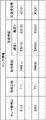
- FIG. 2 is a diagram showing an example of sensor information in the first embodiment.
- the sensor information includes a sensor information ID (IDentification), an acquisition date and time, an acquisition section, image information, and acceleration information.
- IDentification sensor information ID
- acquisition date and time an acquisition date and time
- acquisition section an acquisition section
- image information an acquisition section
- acceleration information an acceleration information
- the sensor information ID is an ID that identifies each sensor information.
- the sensor information ID is given by, for example, the vehicle 40.
- the acquisition section indicates the section where the sensor information was acquired.
- the acquisition section is set by the section identification process described later in the road surface management device 20.
- the image information includes a vertical image 1 and a horizontal image 2 as shown in FIG.
- FIG. 3 is a diagram showing an example of the detection result in the first embodiment.
- the detection result shows the result of the abnormality detection of the road surface by the road surface management device 20.
- the detection result includes the above-mentioned sensor information and the detection information.
- the detection information includes an abnormality flag, a detection type, and a detection status.
- the abnormality flag indicates that an abnormality has been detected (Y) or has not been detected (N) with respect to the sensor information.
- the detection type indicates the type of detected abnormality.
- Examples of the type of abnormality include “cracking” generated on the runway, “wadachibore”, “pothole”, “foreign matter”, and “flatness abnormality”.
- the detection status indicates the degree of deterioration according to the detection type.
- the degree of deterioration for example, the crack rate is used for the detection type “crack”, and the rut digging amount or the like is used for the detection type “wadachibore”.
- the International Roughness Index (IRI) may be used for the detection type “flatness abnormality”.
- the maintenance index Maintenance Control Index (MCI)
- MCI is a composite deterioration index obtained from the crack rate, the amount of rutting, flatness, and the like.
- the terminal device 50 displays an abnormality detection result and a section in which the vehicle 40 on which the own terminal is mounted is currently located.
- the staff of the facility management facility goes to the point where the abnormality of the traveling route is detected with reference to the section where the vehicle 40 is currently located displayed on the terminal device 50, confirms the abnormality of the traveling route, and performs maintenance.
- the moving body for transmitting the sensor information is the vehicle 40.
- the moving body can acquire the sensor information and transmit it to the road surface management device 20, the moving body will be equipped with a bicycle, a drone, and an automatic driving function. It may be a robot, a vehicle, or a person.
- the target of abnormality detection based on the sensor information is the pavement of the travel path
- the target of abnormality detection may be a guide light or a lamp installed on the travel path.
- a guide light or a lamp is used as the above-mentioned detection type.
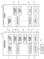
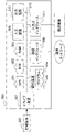
- FIG. 4 is a block diagram showing the configuration of the road surface management device 20 and the terminal device 50 in the first embodiment.
- the road surface management device 20 includes a sensor information acquisition unit 21, a sensor information storage unit 22, a division identification unit 23, a marked object information storage unit 24, a division information storage unit 25, a division information generation unit 251 and an abnormality. It includes a detection unit 26, a detection result storage unit 27, a display control unit 28, and a transmission / reception unit 29.
- the sensor information acquisition unit 21 acquires sensor information from the vehicle 40.
- the sensor information acquisition unit 21 outputs the acquired sensor information to the sensor information storage unit 22.
- the sensor information storage unit 22 stores the sensor information output by the sensor information acquisition unit 21.
- the section specifying unit 23 uses the section information and the marking information to perform a section specifying process for specifying the section in which the image included in the sensor information is taken.
- the section specifying unit 23 sets the specified section in the sensor information.
- the section information storage unit 25 stores section information for each type of runway such as a runway, a tarmac, and taxiway (hereinafter, also referred to as a runway type).
- the section information indicates the positional relationship between each section and the marking on the track in the track divided into a plurality of sections.
- the traveling path is divided into, for example, rectangular sections having a specific size along the traveling direction of the traveling path.
- the sign is one or more of the indicator signs, ground zone signs, runway centerline signs, and other road markings drawn on the runway, and the runway lights, runway centerline lights, and other road markings. including.
- FIG. 5 is a diagram showing an example of the positional relationship shown by the section information in the first embodiment.
- FIG. 5 is an example when the runway is a runway.
- the traveling path is divided into rectangular sections along the vertical direction (traveling direction).
- the vertical length of the section is set to the length (L01 + R01) obtained by adding the marking interval (R01) to the vertical length (L01) of the runway center line marker CL.
- the lateral length is set to a length (W / 6) obtained by dividing the lateral length of the traveling path into six equal parts of W.
- each section is given a section ID for identifying the section on the road.
- the section ID indicates, for example, the type of the runway (runway: RW, taxiway: TW, parking apron: AP), the symbols a to f indicating the horizontal position of the section, and the vertical position. It is composed of symbols 01 to 99.
- the division information may be preset by the staff or the like based on, for example, a drawing of the traveling route, an image of the traveling route such as a satellite photograph or an aerial photograph.
- the image of the traveling path may be an image obtained from an image taken while traveling on the traveling path by the vehicle 40.
- the section information generation unit 251 may generate section information based on a drawing or an image of a travel path.
- the section information generation unit 251 divides the traveling path into a plurality of sections and generates section information by extracting the positional relationship between the plurality of sections and the marking.
- the section information generation unit 251 detects the horizontal length and the vertical length of each section, for example, in an image obtained by the camera of the vehicle 40, in a region where each section is not distorted (appropriately detects an abnormality on the road surface). It may be determined to be an area where a predetermined image quality can be obtained, such as an area where the image quality is determined. In this case, the area where a predetermined image quality can be obtained may be designated by the staff or the like based on the image, or may be determined by the section information generation unit 251 based on the image.
- Similar section information is set or generated in advance even when the travel route is a parking apron or a taxiway.
- the marking information storage unit 24 stores the marking information.
- the marking information indicates information about the above-mentioned marking.
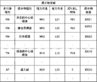
- FIG. 6 is a diagram showing an example of marking information in the first embodiment.
- the marking information includes a traveling road type, a marking type, a horizontal length, a vertical length, a repetition interval, and a marking image.
- the marking type indicates the type of marking on the travel path.
- the lateral length indicates the lateral length of the marking.
- the vertical length indicates the vertical length of the marking.
- the repeating direction indicates a repeating direction (vertical direction or horizontal direction) of a sign that is repeatedly set on the traveling path, for example, such as a runway center line sign.
- the repetition interval indicates the repetition interval of the marking that is repeatedly set on the road.
- the marking image shows an image of the marking.
- the marking is not limited to the above-mentioned marking, and a running path or a structure arranged around the running path may be used.
- a running path or a structure arranged around the running path may be used.
- the travel route type is a tarmac
- a structure around the tarmac such as an airport terminal or a gate may be used as a marking.
- the same information is set in the marking information for these structures and the like.
- the marking information may include an identification model (discriminative device) for identifying various markings from the image.
- the abnormality detection unit 26 uses a known technique to detect an abnormality, that is, detect and determine the presence / absence of an abnormality in the traveling path and the type of abnormality by analyzing the sensor information based on the acquired sensor information. For example, the road surface management device 20 analyzes the image information included in the sensor information by using an analysis model in which an image of an abnormality of the traveling road is learned by machine learning. Then, the abnormality detection unit 26 calculates the degree of deterioration of the detected abnormality of the traveling path. The abnormality detection unit 26 outputs the result of abnormality detection as a detection result to the detection result storage unit 27.
- the detection result storage unit 27 stores the detection result output by the abnormality detection unit 26.
- the display control unit 28 generates a detection result screen showing an abnormality detection result and displays it on the display device 30 or the terminal device 50.
- the transmission / reception unit 29 transmits a detection result display image to the terminal device 50.
- the terminal device 50 includes a transmission / reception unit 51, an image information acquisition unit 52, a display unit 53, an input unit 54, a division identification unit 55, a marking information storage unit 56, a division information storage unit 57, and The display control unit 58 is included.
- the transmission / reception unit 51 receives the detection result screen from the road surface management device 20.
- the image information acquisition unit 52 acquires image information including a vertical image and a horizontal image of the traveling path acquired by the main camera and the side camera of the vehicle 40.
- the section specifying unit 55 performs the section specifying process using the section information and the marking information, so that the section in which the image included in the image information is taken, that is, the vehicle 40 ( The section where the terminal device 50) is currently located is specified.
- the section information storage unit 57 stores the same section information as the section information stored in the section information storage unit 25.
- the marking information storage unit 56 stores the same section information as the marking information stored in the marking information storage unit 24.
- the road surface management device 20 transmits the updated section information and marking information to the terminal device 50, and the section It may be stored in the information storage unit 57 or the marking information storage unit 56.
- the display control unit 58 causes the display unit 53 to display the detection result screen received from the road surface management device 20. Further, the display control unit 58 displays the section where the vehicle 40 is currently located, which is specified by the section specifying section 55, in the map frame of the detection result screen.
- the display unit 53 displays the detection result screen.
- the display unit 53 is, for example, a display device.
- the input unit 54 receives operation instructions from staff and the like.
- the input unit 54 is, for example, a touch panel provided on the surface of the display device.
- the runway is a runway
- the section information storage unit 25 and the section information storage unit 57 have section information indicating the positional relationship of FIG. 5
- the marking information storage unit 24 has a marking information storage unit 56. It is assumed that the marking information of FIG. 6 is stored in. Further, the vehicle 40 shall acquire a vertical image of the traveling path by the main camera and a horizontal image of the traveling path by the side camera while traveling in the vertical direction of the traveling path.
- the detection result display process is a process of detecting an abnormality in the travel path based on the sensor information transmitted from each vehicle 40 and displaying the detection result.
- FIG. 7 is a flowchart showing the detection result display process of the road surface management system 10 in the first embodiment.
- the sensor information acquisition unit 21 of the road surface management device 20 acquires sensor information (acquisition time, image information, and acceleration information) transmitted from the vehicle 40, for example, as shown in FIG. (Step S11).
- the sensor information acquisition unit 21 stores the acquired sensor information in the sensor information storage unit 22.
- the section specifying unit 23 performs a section specifying process for each acquired sensor information using the section information and the marking information (step S12).
- the section specifying unit 23 sets the specified section as a sensor information acquisition section.
- step S12 the details of the section identification process (step S12) will be described.
- a method of specifying a horizontal section in the section specifying process will be described with reference to FIGS. 8 to 10.
- the lateral section is, for example, the lateral reference indicator and the image center with respect to a known lateral section length with respect to the position of a predetermined lateral reference indicator in the longitudinal image of the track. It is specified using the lateral relative distance between them.
- the lateral reference marking is, for example, a marking that exists only in one place on the horizontal straight line of the traveling path.
- a lateral reference sign if it is a runway, for example, the runway centerline sign in FIG. 5 can be used.
- a taxiway for example, a taxiway centerline sign or the like can be used, and if it is a parking apron, for example, a guideline or the like can be used.
- the known lateral section length for example, the lateral section length from the marking to the end of the traveling path or the lateral length of the marking is used.
- FIG. 8 is a flowchart showing a section specifying process in the horizontal direction in the section specifying process (step S12) in the first embodiment.
- the section specifying unit 23 acquires a vertical image from the sensor information (step S1211).
- the section specifying unit 23 identifies the lateral reference sign from the acquired image (step S1212).
- the identification of the marking is performed by, for example, pattern matching with the image of the marking included in the marking information or using an identification model (discriminative device).
- the section specifying unit 23 calculates the relative distance between the lateral reference sign and the image center with respect to the known lateral section length (step S1213).
- the section specifying unit 23 acquires the lateral length from the marking information.
- the section specifying unit 23 identifies the section in the horizontal direction in which the image was taken by using the section information, the position of the lateral reference sign in the image, and the calculated relative distance (step S1214).
- the section specifying unit 23 specifies a position in the section information that is laterally separated from the position of the lateral reference sign in the image. Then, the section specifying unit 23 specifies a lateral section including the specified position in the section information.
- FIG. 9 is a diagram illustrating an example of a method of specifying a lateral section in the first embodiment.
- the runway centerline sign is used as the lateral reference sign, and the section from the runway centerline sign to the runway end is used as the known lateral section length.
- the section specifying unit 23 identifies the runway centerline sign CL from the image.
- the section specifying portion 23 includes the distance between the runway centerline marker CL and the section at the end of the runway (W / 2 which is 1/2 of the lateral length of the runway) and the runway centerline.
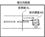
- FIG. 10 is a diagram illustrating another example of the method of specifying the lateral section in the first embodiment.
- the runway centerline sign is used as the lateral reference sign
- the lateral length of the runway centerline sign is used as the known lateral section length.
- the section specifying unit 23 identifies the runway centerline sign CL from the image.
- the section specifying unit 23 acquires the lateral length W01 of the runway center line sign CL from the marking information of FIG.
- the section specifying unit 23 compares the lateral length W01 of the runway center line marker CL with the lateral distance L from the runway center line marker CL to the virtual line DL in the center of the image.
- the distance L is calculated as 5 ⁇ W01.
- the vertical section is, for example, a vertical reference sign and an image center with respect to a known vertical section length based on the position of a predetermined vertical reference sign in the horizontal image of the travel path. It is specified using the vertical relative distance between them.
- the vertical reference sign is, for example, a sign that exists only in one place on a straight line in the vertical direction of the traveling path.
- a vertical reference sign if it is a runway, for example, an instruction sign in FIG. 5 can be used.
- a stop position guide sign or the like can be used, and if it is a parking apron, for example, a spot number or the like can be used.
- the known vertical section length for example, the vertical length of the marking or the repeating interval of the marking repeatedly installed in the vertical direction is used.
- FIG. 11 is a flowchart showing a section specifying process in the vertical direction in the section specifying process (step S12) in the first embodiment.
- the section specifying unit 23 acquires a lateral image from the sensor information (step S1221).
- the section specifying unit 23 identifies the vertical reference sign from the acquired image (step S1222). Here, the section specifying unit 23 identifies the vertical reference sign as in step S1212.
- the section specifying unit 23 calculates the relative distance between the vertical reference sign and the center of the image with respect to the known vertical section length (step S1223).
- the section specifying unit 23 is the markings. Obtain the vertical length and repeat interval from the information.
- the section specifying unit 23 identifies the section in the vertical direction in which the image was taken by using the section information, the position of the vertical reference sign in the image, and the calculated relative distance (step S1224).
- the section specifying unit 23 specifies a position in the section information that is relatively far away in the vertical direction from the position of the vertical reference sign in the image. Then, the section specifying unit 23 specifies a vertical section including the specified position in the section information.
- FIG. 12 is a diagram illustrating an example of a method of specifying a vertical section in the first embodiment.
- the instruction sign is used as the vertical reference sign, and the vertical length of the instruction sign is used as the known vertical section length.
- the section specifying unit 23 identifies the instruction sign ND from the image.
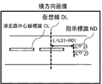
- FIG. 13 is a diagram illustrating another example of the method of specifying the vertical section in the first embodiment.
- the indicator is used as the vertical reference sign, and the vertical length of the runway centerline marker and the repeat interval are used as the known vertical section length.
- the section specifying unit 23 identifies the instruction sign ND and the runway center line sign CL from the image.
- the section specifying unit 23 acquires the vertical length L01 of the runway center line marker CL and the repetition interval R01 from the marking information of FIG.
- the section specifying unit 23 compares the vertical length L01 and the repetition interval R01 of the runway center line sign CL with the vertical distance L from the instruction sign ND to the virtual line DL in the center of the image.
- the distance L is calculated as L01 + R01.
- the section specifying unit 23 displays an image of one or more acquisition times before or after the section specifying target until the vertical reference sign appears.
- a composite image obtained by joining in the vertical direction may be used.
- the vertical section is specified by performing the processing of FIGS. 12 and 13 with reference to the predetermined vertical reference sign using the composite image.
- the section specifying unit 23 identifies the section in which the image was taken as, for example, RW03b by these horizontal and vertical section specifying processes.
- the vertical image is used to specify the horizontal section
- the horizontal image is used to specify the vertical section.
- the present invention is not limited to this, and the horizontal image is used to specify the horizontal section.
- a directional image may be used, or a vertical image may be used to identify a vertical section.
- the abnormality detection unit 26 detects an abnormality in the traveling path for each of the acquired sensor information (step S13).
- the abnormality detection unit 26 associates the sensor information with the detection information and generates a detection result.
- the abnormality detection unit 26 generates the detection result as shown in FIG.
- the abnormality detection unit 26 stores the generated detection result in the detection result storage unit 27.
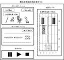
- FIG. 14 is a diagram showing an example of a detection result screen displayed on the display device 30 in the first embodiment.
- the detection result screen includes a main camera frame, a side camera frame, a map frame, and operation buttons.
- a vertical image taken by the main camera of the vehicle 40 is displayed on the main camera frame.
- a horizontal image taken by the side camera is displayed on the side camera frame.
- In the map frame a map of the travel path divided into a plurality of sections is displayed.
- the operation buttons pause, play, stop, etc.
- an image in a desired direction may be displayed on the main camera frame, for example, according to the rotation operation of the staff.
- the main camera frame and the side camera frame are each divided into two, and images in the traveling direction and the subsequent direction are displayed on the divided main camera frame, respectively. Images in the left-right lateral direction with respect to the traveling direction may be displayed on the side camera frame divided into two.
- the display control unit 28 displays, for example, an image included in the sensor information of the detection result on the main camera frame and the side camera frame in response to the operation of the operation buttons of the staff or the like. At this time, the display control unit 28 highlights the acquired section of the displayed image on the map frame. For example, the display control unit 28 displays a predetermined icon in the acquisition section on the map frame. Further, the display control unit 28 may color the acquisition section of the image or blink the acquisition section. In the example of FIG. 14, a white circle icon is displayed in the acquisition section RW03b of the displayed image.
- the display control unit 28 transfers the image of the sensor information in which the section is set as the acquisition section in the detection result to the main camera frame and the side camera frame. It may be displayed.
- the display control unit 28 highlights the acquisition section of the sensor information in which the abnormality is detected on the map frame based on the detection result.
- the display control unit 28 may highlight the acquisition section in which the abnormality is detected according to the detection type.
- the display control unit 28 displays a predetermined icon according to the type of abnormality in the acquisition section where the abnormality is detected.
- the display control unit 28 may color the acquisition section in which the abnormality is detected, or blink the acquisition section.
- the section RW03b in which the abnormality is detected is shown by diagonal lines.
- the display control unit 28 may highlight the acquisition section in which the abnormality is detected according to the detection state.
- the display control unit 28 displays the icon to be displayed in the acquisition section where the abnormality is detected and the color to be attached in different colors such as blue, red, or yellow depending on the detection state (crack rate, etc.).
- the staff and the like can visually grasp the section where the abnormality is detected on the traveling path, the detection type, and the detection state at a glance.
- the display control unit 28 displays the detection information (detection type, detection state, etc.) on the detection result screen.
- the display control unit 28 may overlay the detection result on the image.
- the display control unit 28 may indicate the place where the abnormality is detected on the image.
- the detection type “crack” and the detection state “crack rate: 33.3%” are displayed on the image of the main camera frame in which the abnormality is detected, and the crack detection location is shown.
- the display control unit 28 detects an index (crack rate, IRI, MCI, etc.) related to the degree of deterioration included in the detection state of the detection result regardless of the presence or absence of abnormality detection in the sensor information of the displayed image. It may be displayed on the result screen.
- an index rack rate, IRI, MCI, etc.
- the camera of the vehicle 40 is only the main camera, only the image of the main camera is displayed on the detection result screen.
- the staff etc. can grasp the section where the abnormality is detected in the traveling path.
- the current section display process is a process of identifying and displaying the section in which the vehicle 40 is currently located when the staff or the like heads for the point on the road where an abnormality is detected by the vehicle 40.
- FIG. 15 is a flowchart showing the current section display process of the road surface management system 10 in the first embodiment.
- the display control unit 58 of the terminal device 50 acquires a detection result screen from the road surface management device 20 in response to an operation by a staff member or the like (step S21).
- the display control unit 28 of the road surface management device 20 transmits a detection result screen to the terminal device 50 in response to a request from the terminal device 50.
- the detection result screen is displayed on the display unit 53 via the transmission / reception unit 29, the transmission / reception unit 51, and the display control unit 58.
- the display control unit 58 causes the display unit 53 to display the received detection result screen (step S22).
- the display control unit 28 of the road surface management device 20 responds to the operation of the operation buttons from the staff or the like in the above-mentioned step S14, and the image included in the sensor information, the section in which the abnormality is detected, and the abnormality.
- the detection result (detection type, detection status, etc.) of is displayed on the detection result screen.
- the operation of the operation buttons from the staff or the like is input to the display control unit 28 via the input unit 54, the transmission / reception unit 51, and the transmission / reception unit 29.
- the image information acquisition unit 52 acquires image information including a vertical image of the traveling path and a horizontal image (step S23).
- the section specifying unit 55 performs a section specifying process on the acquired image information using the section information and the marking information (step S24).
- the section specifying unit 55 identifies the section in which the vehicle 40 is currently located by the section specifying process.
- the display control unit 58 displays the section in which the vehicle 40 is currently located, which is specified by the section specifying section 55, in the map frame of the detection result screen (step S25).
- the display control unit 58 highlights the section where the vehicle 40 is currently located on the map frame.
- the display control unit 58 may display a predetermined icon on the map frame in the section where the vehicle 40 is currently located as a highlighting. Further, the display control unit 58 may color the section where the vehicle 40 is currently located or blink the section.
- FIG. 16 is a diagram showing an example of a detection result screen displayed on the display unit 53 in the first embodiment.
- a black circle icon is displayed in the section RW02b where the vehicle 40 is currently located.
- step S23 the process from step S23 is repeated.
- the section in which the vehicle 40 is currently located which is shown in the map frame of the detection result screen, also moves.
- the staff or the like can reach the section where the abnormality in the traveling path is detected by checking the detection result screen as shown in FIG.
- the terminal device 50 when the terminal device 50 is mounted on the vehicle 40 and the image acquired by the main camera and the side camera of the vehicle 40 is used to specify the section where the vehicle 40 (terminal device 50) is currently located.
- the terminal device 50 when the terminal device 50 is a tablet or a smartphone carried by an employee, the section in which the vehicle 40 (terminal device 50) is currently located is specified by using the image acquired by the camera of the terminal device 50. You may. In this case, the vertical image and the horizontal image may be acquired by the staff while pointing the camera of the terminal device 50 in the vertical direction and the horizontal direction of the traveling path.
- the terminal device 50 does not have to be mounted on the vehicle 40.
- the terminal device 50 may specify the section in which the terminal device 50 is currently located by using the image acquired by the camera of the terminal device 50.
- the road surface management device 20 and the terminal device 50 may also use a position information acquisition device such as GPS provided in the vehicle 40 in combination to specify the section in which the image is taken.
- the vehicle 40 includes the position information acquired by the position information acquisition device in the sensor information and transmits the position information to the road surface management device 20.
- the road surface management device 20 and the terminal device 50 specify, for example, the approximate position of the section where the image was taken based on the position information and the section information acquired by the position information acquisition device, and use the image taken by the camera of the vehicle 40 as the image. Based on the location of the final compartment. As a result, the road surface management device 20 and the terminal device 50 can specify the section where the image is taken with higher accuracy.
- the division identification unit 23 of the road surface management device 20 has a positional relationship between a plurality of divisions of the airport's driving route and the markings, and the markings in the image included in the sensor information collected on the traveling route. And, among the plurality of sections, the section in which the image was taken is specified, and the abnormality detection unit 26 detects the abnormality of the traveling path in the specified section based on the collected sensor information. This is because the display control unit 28 outputs the detected abnormality in association with the specified section. (Second embodiment) The second embodiment will be described.
- FIG. 17 is a block diagram showing the configuration of the road surface management device 1 in the second embodiment.
- the road surface management device 1 includes a specific unit 2, a detection unit 3, and an output unit 4.
- the specific unit 2, the detection unit 3, and the output unit 4 are embodiments of the specific means, the detection means, and the output means of the present disclosure, respectively. Further, the specific unit 2, the detection unit 3, and the output unit 4 correspond to the section identification unit 23, the abnormality detection unit 26, and the display control unit 28, respectively, of the first embodiment.
- the specific unit 2 is based on the positional relationship between the markings and the plurality of sections that divide the travel path of the airport and the markings in the image included in the sensor information collected in the travel path. Identify the section in which the image was taken.
- the specific unit 2 is based on, for example, a preset positional relationship and sensor information acquired from a vehicle that captures an image of the travel path while traveling on the travel path and collects sensor information including the image. Identify the parcel.
- the detection unit 3 detects an abnormality in the travel path in the specified section based on the collected sensor information.
- the detection unit 3 detects an abnormality by analyzing sensor information using, for example, an analysis model.
- the output unit 4 outputs the detected abnormality in association with the specified section.
- the output unit 4 displays, for example, the detected abnormality on a display device or the like.
- each component of the road surface management device 20 and the terminal device 50 indicates a block of functional units. Some or all of the components of each device may be realized by any combination of the computer 500 and the program.
- FIG. 18 is a block diagram showing an example of the hardware configuration of the computer 500.
- the computer 500 may include, for example, a CPU (Central Processing Unit) 501, a ROM (Read Only Memory) 502, a RAM (Random Access Memory) 503, a program 504, a storage device 505, a drive device 507, and a communication interface 508. , Input device 509, output device 510, input / output interface 511, and bus 512.
- a CPU Central Processing Unit
- ROM Read Only Memory
- RAM Random Access Memory
- the program 504 includes an instruction for realizing each function of each device.
- the program 504 is stored in the ROM 502, the RAM 503, and the storage device 505 in advance.
- the CPU 501 realizes each function of each device by executing the instruction included in the program 504.
- the CPU 501 of the road surface management device 20 executes an instruction included in the program 504
- the functions of the sensor information acquisition unit 21, the section identification unit 23, the abnormality detection unit 26, the display control unit 28, and the transmission / reception unit 29 can be performed. Realize.
- the RAM 503 of the road surface management device 20 may store the data of the section information storage unit 25.
- the storage device 505 of the road surface management device 20 may store the data of the sensor information storage unit 22, the marking information storage unit 24, and the detection result storage unit 27.
- the drive device 507 reads and writes the recording medium 506.
- the communication interface 508 provides an interface with a communication network.
- the input device 509 is, for example, a mouse, a keyboard, or the like, and receives input of information from an operator or the like.
- the output device 510 is, for example, a display, and outputs (displays) information to an operator or the like.
- the input / output interface 511 provides an interface with peripheral devices. Bus 512 connects each component of these hardware.
- the program 504 may be supplied to the CPU 501 via the communication network, or may be stored in the recording medium 506 in advance, read by the drive device 507, and supplied to the CPU 501.
- FIG. 18 Note that the hardware configuration shown in FIG. 18 is an example, and components other than these may be added or may not include some components.
- the road surface management device 20 may be realized by any combination of a computer and a program that are different for each component.
- a plurality of components included in each device may be realized by any combination of one computer and a program.
- each component of each device may be realized by a general-purpose or dedicated circuitry including a processor or the like, or a combination thereof. These circuits may be composed of a single chip or a plurality of chips connected via a bus. A part or all of each component of each device may be realized by the combination of the circuit or the like and the program described above.
- each component of each device when a part or all of each component of each device is realized by a plurality of computers, circuits, etc., the plurality of computers, circuits, etc. may be centrally arranged or distributed.
Landscapes
- Engineering & Computer Science (AREA)
- Physics & Mathematics (AREA)
- General Physics & Mathematics (AREA)
- Multimedia (AREA)
- Theoretical Computer Science (AREA)
- Quality & Reliability (AREA)
- Architecture (AREA)
- Civil Engineering (AREA)
- Structural Engineering (AREA)
- Traffic Control Systems (AREA)
- Road Repair (AREA)
Priority Applications (3)
| Application Number | Priority Date | Filing Date | Title |
|---|---|---|---|
| JP2022553240A JP7364093B2 (ja) | 2020-09-29 | 2020-09-29 | 路面管理装置、路面管理システム、端末装置、路面管理方法、及び、プログラム |
| US18/022,410 US12577742B2 (en) | 2020-09-29 | 2020-09-29 | Road surface management device, road surface management method, and recording medium |
| PCT/JP2020/036770 WO2022070230A1 (ja) | 2020-09-29 | 2020-09-29 | 路面管理装置、路面管理方法、端末装置、及び、記録媒体 |
Applications Claiming Priority (1)
| Application Number | Priority Date | Filing Date | Title |
|---|---|---|---|
| PCT/JP2020/036770 WO2022070230A1 (ja) | 2020-09-29 | 2020-09-29 | 路面管理装置、路面管理方法、端末装置、及び、記録媒体 |
Publications (1)
| Publication Number | Publication Date |
|---|---|
| WO2022070230A1 true WO2022070230A1 (ja) | 2022-04-07 |
Family
ID=80951442
Family Applications (1)
| Application Number | Title | Priority Date | Filing Date |
|---|---|---|---|
| PCT/JP2020/036770 Ceased WO2022070230A1 (ja) | 2020-09-29 | 2020-09-29 | 路面管理装置、路面管理方法、端末装置、及び、記録媒体 |
Country Status (3)
| Country | Link |
|---|---|
| US (1) | US12577742B2 (https=) |
| JP (1) | JP7364093B2 (https=) |
| WO (1) | WO2022070230A1 (https=) |
Cited By (1)
| Publication number | Priority date | Publication date | Assignee | Title |
|---|---|---|---|---|
| CN116343176A (zh) * | 2023-05-30 | 2023-06-27 | 济南城市建设集团有限公司 | 一种路面异常监测系统及其监测方法 |
Families Citing this family (2)
| Publication number | Priority date | Publication date | Assignee | Title |
|---|---|---|---|---|
| US12051229B2 (en) * | 2021-01-14 | 2024-07-30 | Tata Consultancy Services Limited | System and method for attention-based surface crack segmentation |
| CN119478642B (zh) * | 2025-01-14 | 2025-03-25 | 四川能投建工集团有限公司 | 基于多源数据分析的沥青路面离析智能检测方法 |
Citations (6)
| Publication number | Priority date | Publication date | Assignee | Title |
|---|---|---|---|---|
| JP2006258486A (ja) * | 2005-03-15 | 2006-09-28 | Nagoya City | 座標計測装置と座標計測方法 |
| JP2013167494A (ja) * | 2012-02-14 | 2013-08-29 | Fujitsu Ltd | 構造物点検支援方法、構造物点検支援プログラム及び構造物点検支援装置 |
| WO2018037689A1 (ja) * | 2016-08-22 | 2018-03-01 | 富士フイルム株式会社 | 画像処理装置及び画像処理方法 |
| WO2020022042A1 (ja) * | 2018-07-25 | 2020-01-30 | 日本電気株式会社 | 劣化診断装置、劣化診断システム、劣化診断方法、プログラムを記憶する記憶媒体 |
| JP2020056303A (ja) * | 2015-07-21 | 2020-04-09 | 株式会社東芝 | ひび割れ解析装置、ひび割れ解析方法及びひび割れ解析プログラム |
| WO2020154004A2 (en) * | 2018-10-26 | 2020-07-30 | The Regents Of The University Of California | Nano-treatment of high strength aluminum alloys for manufacturing processes |
Family Cites Families (4)
| Publication number | Priority date | Publication date | Assignee | Title |
|---|---|---|---|---|
| US10467483B2 (en) * | 2014-02-28 | 2019-11-05 | Pioneer Corporation | Image acquiring system, terminal, image acquiring method, and image acquiring program |
| US10402995B2 (en) * | 2017-07-27 | 2019-09-03 | Here Global B.V. | Method, apparatus, and system for real-time object detection using a cursor recurrent neural network |
| JP6932057B2 (ja) | 2017-10-06 | 2021-09-08 | 大林道路株式会社 | 路面性状調査装置及び路面性状調査システム |
| JP7004543B2 (ja) * | 2017-10-30 | 2022-01-21 | 株式会社Ihi | 路面状態検知装置、及び路面状態検知システム |
-
2020
- 2020-09-29 WO PCT/JP2020/036770 patent/WO2022070230A1/ja not_active Ceased
- 2020-09-29 JP JP2022553240A patent/JP7364093B2/ja active Active
- 2020-09-29 US US18/022,410 patent/US12577742B2/en active Active
Patent Citations (6)
| Publication number | Priority date | Publication date | Assignee | Title |
|---|---|---|---|---|
| JP2006258486A (ja) * | 2005-03-15 | 2006-09-28 | Nagoya City | 座標計測装置と座標計測方法 |
| JP2013167494A (ja) * | 2012-02-14 | 2013-08-29 | Fujitsu Ltd | 構造物点検支援方法、構造物点検支援プログラム及び構造物点検支援装置 |
| JP2020056303A (ja) * | 2015-07-21 | 2020-04-09 | 株式会社東芝 | ひび割れ解析装置、ひび割れ解析方法及びひび割れ解析プログラム |
| WO2018037689A1 (ja) * | 2016-08-22 | 2018-03-01 | 富士フイルム株式会社 | 画像処理装置及び画像処理方法 |
| WO2020022042A1 (ja) * | 2018-07-25 | 2020-01-30 | 日本電気株式会社 | 劣化診断装置、劣化診断システム、劣化診断方法、プログラムを記憶する記憶媒体 |
| WO2020154004A2 (en) * | 2018-10-26 | 2020-07-30 | The Regents Of The University Of California | Nano-treatment of high strength aluminum alloys for manufacturing processes |
Cited By (2)
| Publication number | Priority date | Publication date | Assignee | Title |
|---|---|---|---|---|
| CN116343176A (zh) * | 2023-05-30 | 2023-06-27 | 济南城市建设集团有限公司 | 一种路面异常监测系统及其监测方法 |
| CN116343176B (zh) * | 2023-05-30 | 2023-08-11 | 济南城市建设集团有限公司 | 一种路面异常监测系统及其监测方法 |
Also Published As
| Publication number | Publication date |
|---|---|
| US20230357998A1 (en) | 2023-11-09 |
| JP7364093B2 (ja) | 2023-10-18 |
| US12577742B2 (en) | 2026-03-17 |
| JPWO2022070230A1 (https=) | 2022-04-07 |
Similar Documents
| Publication | Publication Date | Title |
|---|---|---|
| US11959771B2 (en) | Creation and use of enhanced maps | |
| US10068133B2 (en) | Pavement marking determination | |
| US20200042800A1 (en) | Image acquiring system, terminal, image acquiring method, and image acquiring program | |
| CA2862762C (en) | Method and apparatus for detection of foreign object debris | |
| JP7364093B2 (ja) | 路面管理装置、路面管理システム、端末装置、路面管理方法、及び、プログラム | |
| KR101910066B1 (ko) | 도로 포장관리 시스템 | |
| EP2703774A1 (en) | Monitoring method and monitoring system of settlement of engineering buildings | |
| JP7600872B2 (ja) | 情報処理装置、情報処理方法、及び、プログラム | |
| JP2022155303A (ja) | 路面の損傷の測定方法 | |
| WO2020004424A1 (ja) | 検知領域データベース作成装置 | |
| Askarzadeh et al. | Drones for road condition monitoring: applications and benefits | |
| JP2008292291A (ja) | ナビゲーション装置 | |
| JP7336415B2 (ja) | 補修計画策定装置 | |
| WO2023145402A1 (ja) | 交通流計測システムおよび交通流計測方法 | |
| WO2023145401A1 (ja) | 交通流計測システムおよび交通流計測方法 | |
| CN118053084B (zh) | 一种基于无人机的道路路面异常检测方法及巡检系统 | |
| CN119851518A (zh) | 跑道入侵探测 | |
| JP2023112536A (ja) | 路面損傷位置の算定方法 | |
| Santos et al. | Use of Unmanned Aerial Vehicles (UAVs) for Transport Pavement Inspection | |
| RU2616103C2 (ru) | Способ автоматизированного составления схемы дорожно-транспортного происшествия с использованием системы глобального позиционирования и фотокамеры | |
| TWI810921B (zh) | 交通肇事路段改善規劃方法及系統 | |
| CN119323877B (zh) | 基于路线规划的智能路标指示系统 | |
| CN119027295A (zh) | 一种基于ar全景技术的道路交通安全隐患排查方法与系统 | |
| CN221784353U (zh) | 一种道路巡检数据采集及处理装置 | |
| Askarzadeh | Quantitative Evaluation of Drone-Based Linear Asset Condition Monitoring |
Legal Events
| Date | Code | Title | Description |
|---|---|---|---|
| 121 | Ep: the epo has been informed by wipo that ep was designated in this application |
Ref document number: 20956160 Country of ref document: EP Kind code of ref document: A1 |
|
| ENP | Entry into the national phase |
Ref document number: 2022553240 Country of ref document: JP Kind code of ref document: A |
|
| NENP | Non-entry into the national phase |
Ref country code: DE |
|
| 122 | Ep: pct application non-entry in european phase |
Ref document number: 20956160 Country of ref document: EP Kind code of ref document: A1 |
|
| WWG | Wipo information: grant in national office |
Ref document number: 18022410 Country of ref document: US |