WO2022065482A1 - 光ファイバ母材の製造方法および製造設備 - Google Patents
光ファイバ母材の製造方法および製造設備 Download PDFInfo
- Publication number
- WO2022065482A1 WO2022065482A1 PCT/JP2021/035364 JP2021035364W WO2022065482A1 WO 2022065482 A1 WO2022065482 A1 WO 2022065482A1 JP 2021035364 W JP2021035364 W JP 2021035364W WO 2022065482 A1 WO2022065482 A1 WO 2022065482A1
- Authority
- WO
- WIPO (PCT)
- Prior art keywords
- burners
- core
- optical fiber
- base material
- fiber base
- Prior art date
- Legal status (The legal status is an assumption and is not a legal conclusion. Google has not performed a legal analysis and makes no representation as to the accuracy of the status listed.)
- Ceased
Links
Images



Classifications
-
- C—CHEMISTRY; METALLURGY
- C03—GLASS; MINERAL OR SLAG WOOL
- C03B—MANUFACTURE, SHAPING, OR SUPPLEMENTARY PROCESSES
- C03B37/00—Manufacture or treatment of flakes, fibres, or filaments from softened glass, minerals, or slags
- C03B37/01—Manufacture of glass fibres or filaments
- C03B37/012—Manufacture of preforms for drawing fibres or filaments
- C03B37/014—Manufacture of preforms for drawing fibres or filaments made entirely or partially by chemical means, e.g. vapour phase deposition of bulk porous glass either by outside vapour deposition [OVD], or by outside vapour phase oxidation [OVPO] or by vapour axial deposition [VAD]
- C03B37/01413—Reactant delivery systems
- C03B37/0142—Reactant deposition burners
-
- C—CHEMISTRY; METALLURGY
- C03—GLASS; MINERAL OR SLAG WOOL
- C03B—MANUFACTURE, SHAPING, OR SUPPLEMENTARY PROCESSES
- C03B37/00—Manufacture or treatment of flakes, fibres, or filaments from softened glass, minerals, or slags
- C03B37/01—Manufacture of glass fibres or filaments
- C03B37/012—Manufacture of preforms for drawing fibres or filaments
- C03B37/014—Manufacture of preforms for drawing fibres or filaments made entirely or partially by chemical means, e.g. vapour phase deposition of bulk porous glass either by outside vapour deposition [OVD], or by outside vapour phase oxidation [OVPO] or by vapour axial deposition [VAD]
- C03B37/01406—Deposition reactors therefor
-
- C—CHEMISTRY; METALLURGY
- C03—GLASS; MINERAL OR SLAG WOOL
- C03B—MANUFACTURE, SHAPING, OR SUPPLEMENTARY PROCESSES
- C03B2201/00—Type of glass produced
- C03B2201/06—Doped silica-based glasses
- C03B2201/30—Doped silica-based glasses doped with metals, e.g. Ga, Sn, Sb, Pb or Bi
- C03B2201/31—Doped silica-based glasses doped with metals, e.g. Ga, Sn, Sb, Pb or Bi doped with germanium
-
- C—CHEMISTRY; METALLURGY
- C03—GLASS; MINERAL OR SLAG WOOL
- C03B—MANUFACTURE, SHAPING, OR SUPPLEMENTARY PROCESSES
- C03B2207/00—Glass deposition burners
- C03B2207/42—Assembly details; Material or dimensions of burner; Manifolds or supports
-
- C—CHEMISTRY; METALLURGY
- C03—GLASS; MINERAL OR SLAG WOOL
- C03B—MANUFACTURE, SHAPING, OR SUPPLEMENTARY PROCESSES
- C03B2207/00—Glass deposition burners
- C03B2207/50—Multiple burner arrangements
-
- C—CHEMISTRY; METALLURGY
- C03—GLASS; MINERAL OR SLAG WOOL
- C03B—MANUFACTURE, SHAPING, OR SUPPLEMENTARY PROCESSES
- C03B2207/00—Glass deposition burners
- C03B2207/50—Multiple burner arrangements
- C03B2207/52—Linear array of like burners
-
- C—CHEMISTRY; METALLURGY
- C03—GLASS; MINERAL OR SLAG WOOL
- C03B—MANUFACTURE, SHAPING, OR SUPPLEMENTARY PROCESSES
- C03B2207/00—Glass deposition burners
- C03B2207/60—Relationship between burner and deposit, e.g. position
- C03B2207/66—Relative motion
Definitions
- This disclosure relates to a manufacturing method and manufacturing equipment of an optical fiber base material.
- This application claims priority based on Japanese Patent Application No. 2020-162358 filed on September 28, 2020, and incorporates all the contents described in the Japanese patent application.
- Patent Document 1 discloses a method of reciprocating the target material with respect to a plurality of burners when the soot is deposited on the target material by the OVD method. The reciprocating movement in Patent Document 1 simply reciprocates between predetermined points.
- Patent Document 2 describes a method for manufacturing a porous glass preform using the OVD method, in which a relative vibrational motion is generated between a plurality of burner arrays arranged along the entire length of the preform and a starting member. So, a method of depositing a glass suit on a starting member is disclosed.
- the vibration motion in Patent Document 2 repeats reciprocating with a length less than the total length of the preform, and changes the turning point in the manufacturing process.
- the method for manufacturing an optical fiber base material is as follows.
- a method for manufacturing an optical fiber base material which manufactures an optical fiber base material having a core portion and a clad portion by using a manufacturing facility equipped with at least three burners.
- a core deposition step of depositing core glass fine particles generated in a flame formed by the burner on the first target material while relatively moving the burner and the first target material back and forth in the first round. While the second target material including the core portion obtained through the core portion deposition step is relatively moved back and forth between the burner and the core portion, the clad glass fine particles generated in the flame formed by the burner are transferred to the core.
- the number of the burners used in the core portion deposition step is less than the number of the burners used in the clad portion deposition step.
- the distance between the turning points in the first reciprocating movement is equal to or greater than the length of the effective portion of the optical fiber base material.
- the clad portion deposition step at least three or more of the burners are used.
- the distance between the turning points in the second round-trip movement is shorter than the distance between the turning points in the first round-trip movement. The turning point in the second reciprocating movement fluctuates during the clad portion deposition process.
- the optical fiber base material manufacturing equipment is An optical fiber base material manufacturing facility that manufactures an optical fiber base material having a core portion and a clad portion. With at least 3 burners A reciprocating movement mechanism for relatively reciprocating the burner and the target material is provided. The number of the burners used in the core portion depositing step of depositing the core portion on the target material is smaller than the number of the burners used in the clad portion depositing step of depositing the clad portion on the core portion. When two or more burners are used in the core deposition step, the distance between the two endmost burners used in the core deposition step is the burner used in the clad deposition step. It is shorter than the distance between the two burners at the end of the.
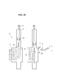
- FIG. 1A is a schematic view showing a core portion deposition process according to an embodiment of the present disclosure.
- FIG. 1B is a schematic view showing a clad portion deposition step according to an embodiment of the present disclosure.
- FIG. 2 is a graph showing the relationship between the number of core burners and the deposition rate.
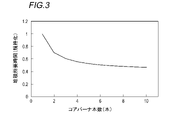
- FIG. 3 is a graph showing the relationship between the number of core burners and the time required for deposition.
- FIG. 4 is a graph showing the relationship between the number of core burners and the reciprocating movement range.
- the OVD method is mentioned as a method of improving the deposition rate, stabilizing the difference in specific refractive index in the longitudinal direction, and facilitating profile control in the radial direction.
- the method disclosed in Patent Document 1 as the number of burners used is increased, the reciprocating distance becomes longer by the increase. Therefore, there is a problem that the manufacturing equipment becomes large. On the other hand, if the number of burners used is reduced, the deposition rate will decrease.
- the deposition rate can be improved while suppressing the increase in size of the manufacturing equipment.
- the core portion is to be deposited by a method as in Patent Document 2
- the amount of Ge or the like added tends to change in the longitudinal direction of the optical fiber base material, and the refractive index distribution tends to fluctuate in the longitudinal direction.
- An object of the present disclosure is the manufacture of an optical fiber base material capable of achieving a sufficient deposition rate while suppressing an increase in the size of equipment and suppressing fluctuations in the refractive index distribution in the longitudinal direction. To provide methods and manufacturing equipment.
- the method for manufacturing an optical fiber base material is as follows.
- a method for manufacturing an optical fiber base material which manufactures an optical fiber base material having a core portion and a clad portion by using a manufacturing facility equipped with at least three burners.
- a core deposition step of depositing core glass fine particles generated in a flame formed by the burner on the first target material while relatively moving the burner and the first target material back and forth in the first round. While the second target material including the core portion obtained through the core portion deposition step is relatively moved back and forth between the burner and the core portion, the clad glass fine particles generated in the flame formed by the burner are transferred to the core.
- the number of the burners used in the core portion deposition step is less than the number of the burners used in the clad portion deposition step.
- the distance between the turning points in the first reciprocating movement is equal to or greater than the length of the effective portion of the optical fiber base material.
- the clad portion deposition step at least three or more of the burners are used.
- the distance between the turning points in the second round-trip movement is shorter than the distance between the turning points in the first round-trip movement. The turning point in the second reciprocating movement fluctuates during the clad portion deposition process.
- a burner that substantially deposits glass fine particle deposits, such as a burner that is only lit, a glass raw material gas such as SiCl 4 or siloxane, or the like. Burners into which only a very small amount of dopant gas such as GeCl 4 is introduced are not included in the number of burners used.
- the method for manufacturing the optical fiber base material is as follows. Two or more burners used in the core deposition step, The distance between the two endmost burners used in the core deposition process is shorter than the distance between the two endmost burners used in the clad deposition process. Is preferable. According to this configuration, since two or more burners are used in the core deposition step, the deposition rate of the glass fine particles can be increased.
- the method for manufacturing the optical fiber base material is as follows.
- the raw material gas of the core glass fine particles may contain GeCl 4 .
- the refractive index of the core portion can be set in a desired range.
- the core deposition step it is preferable to use two or more adjacent burners. According to this configuration, for example, since the adjacent burners are used, the moving distance in the first reciprocating movement can be shortened. As a result, it is possible to further suppress the increase in size of the equipment.
- the method for manufacturing the optical fiber base material is as follows.
- the distance between the adjacent burners is preferably 50 mm or more and 400 mm or less.
- the distance between adjacent burners is preferably 50 mm or more and 400 mm or less.
- the optical fiber base material manufacturing equipment is An optical fiber base material manufacturing facility that manufactures an optical fiber base material having a core portion and a clad portion. With at least 3 burners A reciprocating movement mechanism for relatively reciprocating the burner and the target material is provided. The number of the burners used in the core portion depositing step of depositing the core portion on the target material is smaller than the number of the burners used in the clad portion depositing step of depositing the clad portion on the core portion. When two or more burners are used in the core deposition step, the distance between the two endmost burners used in the core deposition step is the burner used in the clad deposition step. It is shorter than the distance between the two burners at the end of the. According to this configuration, it is possible to achieve a sufficient deposition rate while suppressing the increase in size of the equipment, and it is possible to suppress fluctuations in the refractive index distribution in the longitudinal direction.
- FIG. 1A is a schematic view showing a core portion deposition process according to an embodiment of the present disclosure.
- FIG. 1B is a schematic view showing a clad portion deposition step according to an embodiment of the present disclosure.
- the manufacturing equipment 10 is equipment for manufacturing the core portion or the optical fiber base material M1 having the core portion and a part of the clad portion and the optical fiber base material M2 having the core portion and the clad portion by the OVD method.
- the manufacturing equipment 10 includes a reaction vessel 11, burners 12a to 12g, an elevating device (reciprocating movement mechanism) 13, a support rod 14, and a holder 15.
- the seed rod pipe 16 and the starting rod (first target material) 17 are housed inside the reaction vessel 11.
- the starting member (second target material) 18 is housed inside the reaction vessel 11.
- the first target material and the second target material are collectively referred to as a “target material”.
- the reaction vessel 11 is a vessel for depositing glass fine particles on the target material in the space inside the reaction vessel 11.
- the reaction vessel 11 is made of a material that is less likely to be corroded by hydrogen chloride gas or the like even under high temperature environmental conditions when forming the optical fiber base material, for example, silicon dioxide, silicon carbide, nickel, or a nickel alloy.
- the support rod 14 is inserted into the inside of the reaction vessel 11 from above the reaction vessel 11.
- a holder 15 is connected to the lower end of the support rod 14.
- the cage 15 directly or indirectly holds the target material. Further, the holder 15 can rotate the held target material around the axis of the target material.
- the seed rod pipe 16 is made of, for example, quartz glass.
- the starting rod 17 is made of a material such as alumina, glass, refractory ceramics, carbon and the like.
- the starting member 18 is, for example, a member obtained by solidifying and stretching the optical fiber base material M1 obtained through the core portion deposition step.
- the upper end of the support rod 14 is connected to the elevating device 13.
- the elevating device 13 can reciprocate the target material in the vertical direction by reciprocating the support rod 14 in the vertical direction.
- the reaction vessel 11 is provided with a plurality of burners 12a to 12 g (hereinafter collectively referred to as "burners 12") along the direction in which the target material reciprocates (vertical direction in the example of FIG. 1A).
- the number of burners provided in the manufacturing equipment 10 is not particularly limited as long as it is three or more.
- the distance between adjacent burners is preferably 50 mm or more and 400 mm or less.
- the burners for the clad used in the clad portion deposition step are arranged at equal intervals.
- the burner 12 has a plurality of ports for blowing gas. Each port leads to a pipe for supplying a glass raw material gas containing SiCl 4 and siloxane, and a pipe for supplying a flame forming gas such as oxyhydrogen gas.
- the core burner used in the core deposition process is also connected to a pipe for supplying a dopant gas such as GeCl 4 . From the viewpoint of further suppressing the increase in size of the equipment and suppressing the cost of the equipment, it is preferable to use a part of the clad burner as the core burner.
- the number of core burners is not particularly limited as long as it is less than the number of clad burners.
- the number of burners for the core may be one, but for example, two or more adjacent burners in the manufacturing equipment 10 are preferable. Further, from the viewpoint of successfully balancing the suppression of the increase in size of the equipment and the improvement of the deposition rate, the number of clad burners is preferably about 3/10 to 5/10.
- the distance between the two burners at the end of the core burners is set to the end of the clad burners in order to prevent the equipment from becoming large. It is preferably shorter than the distance between two burners.
- three burners 12c to 12e are burners used in the core deposition process. Further, as shown in FIG. 1B, there are seven clad burners of 12a to 12 g used in the clad portion deposition step.
- the three burners 12c to 12e are burners for both core and clad. Further, the distance between the burner 12c at the top and the burner 12e at the bottom of the core burners, that is, the distance between the two burners at the ends of the core burners is the clad burner. It is shorter than the distance between the burner 12a at the top and the burner 12g at the bottom, that is, the distance between the two burners at the ends of the clad burner.
- the reaction vessel 11 is provided with an exhaust port (not shown) for exhausting exhaust gas.
- An exhaust pipe is connected to the exhaust port, and the internal exhaust gas containing excess glass fine particles not deposited on the target material is sent out from the exhaust port to the exhaust pipe.
- the burner 12 may be configured to reciprocate in the vertical direction.
- the direction of reciprocating movement may be the axial direction of the target material, and the direction of reciprocating movement differs depending on how the target material is held. For example, when the axial direction of the target material is the left-right direction, the manufacturing equipment 10 is configured so that the burner 12 and the target material can relatively reciprocate in the lateral direction.
- the method for manufacturing the optical fiber base material according to the present embodiment will be described with reference to FIGS. 1A and 1B.
- the optical fiber base material M1 having a core portion, a core portion, and a part of the clad portion is used, and the core portion and the clad portion are used in the manufacturing equipment 10 provided with at least three burners 12.
- the core glass particles generated in the flame formed by the core burner are deposited on the starting rod 17 while the core burner and the starting rod 17 are relatively moved back and forth in the first round trip. Then, the optical fiber base material M1 in which the glass fine particles in the core portion are deposited on the surface is manufactured.
- the burners 12c to e are used as the burners for the core.
- the glass raw material gas and the flame forming gas are supplied to the burners 12c to e for the core.
- the glass raw material gas includes, for example, SiCl 4 or siloxane.
- the glass raw material gas used in the core deposition step preferably contains, for example, GeCl 4 as a dopant.
- the amount of GeCl 4 introduced is not particularly limited, but is preferably 0.1 g / min or more, and more preferably 0.5 g / min or more, for example, from the viewpoint of increasing the deposited amount.
- the flame-forming gas is, for example, oxyhydrogen gas, which contains hydrogen, which is a flammable gas, and oxygen, which is a combustible gas.
- the glass raw material gas and the flame forming gas are ejected from the burners 12c to e, and the starting rod 17 is rotated around the axis of the starting rod 17 by the holder 15 in the axial direction of the starting rod 17. Make the first round trip along.
- the first round-trip movement is a simple round-trip movement between two turning points.
- a simple reciprocating movement is performed between the turning point P1 and the turning point P2 as shown by an arrow.
- the folding point P1 is the optical fiber base material M1 when the lower end portion of the optical fiber base material M1 (near the lower end portion of the starting rod 17) is at the same height as the burner 12c at the uppermost stage of the core burners. It is near the position of the upper end of.
- the folding point P2 is near the position of the upper end portion of the optical fiber base material M1 when the upper end portion of the optical fiber base material M1 is at the same height as the burner 12e at the lowermost stage among the burners for the core.
- the folding point P1 is near the position of the upper end portion of the optical fiber base material M1 when the lower end portion of the optical fiber base material M1 is at the same height as the burner for the core. Is.
- the folding point P2 is near the position of the upper end portion of the optical fiber base material M1 when the upper end portion of the optical fiber base material M1 is at the same height as the burner for the core.
- the distance between the folding points P1 and P2 is an effective portion of the optical fiber base material M1 (for example, a portion used for an optical fiber product, and the diameter is constant after the clad portion manufacturing process. It is longer than the length of the part).
- the folding point P1 may move slightly upward.
- the folding point P2 may be slightly moved downward.
- the distance between the turning points P1 and P2 becomes longer, and the manufacturing equipment 10 becomes larger.
- the distance between the two burners at the end of the core burners is set to the maximum among the clad burners. It is shorter than the distance between the two burners at the ends. Therefore, the reciprocating movement amount in the first reciprocating movement is shorter than when all of the burners 12 are used, and as a result, the increase in size of the manufacturing equipment 10 can be suppressed.
- the clad portion deposition step is carried out, for example, in the same manufacturing equipment 10 as the core portion deposition step, following the core portion deposition step.
- the clad portion deposition step the clad glass fine particles generated in the flame formed by the clad burner are deposited on the starting member 18 while the clad burner and the starting member 18 are relatively moved back and forth in the second round trip.
- the optical fiber base material M2 in which the glass fine particles in the clad portion are deposited on the surface is manufactured.
- the burners 12a to 12 g are used as the burners for the cladding.
- the burners 12c to e are burners for both core and clad.
- the glass raw material gas and the flame forming gas are supplied to the clad burners 12a to g.
- the glass raw material gas includes, for example, SiCl 4 or siloxane.
- the glass raw material gas used in the clad portion deposition step does not contain a dopant such as GeCl 4 .
- glass fine particles for clad mainly containing SiO 2 as a main component are generated in the flame of the burners 12a to 12a.
- the flame-forming gas is, for example, oxyhydrogen gas, which contains hydrogen, which is a flammable gas, and oxygen, which is a combustible gas.
- the glass raw material gas and the flame forming gas are ejected from the burners 12a to 12a, and the starting member 18 is rotated around the axis of the starting member 18 by the holder 15 in the axial direction of the starting member 18. Make a second round trip along.
- the second reciprocating movement is a reciprocating movement in which the turning point fluctuates during the clad portion deposition process.
- a reciprocating movement is performed between the turning point P3 and the turning point P8 while changing the turning point many times as shown by an arrow. Specifically, first, the upper end of the optical fiber base material M2 moves downward from the state where it is at the turning point P3, and when the upper end of the optical fiber base material M2 reaches the turning point P4, it moves upward. Is reversed. Next, when the upper end portion of the optical fiber base material M2 reaches the folding point P5, the moving direction is reversed downward.
- the moving direction is reversed at each of the folding points P6 and P7, and the upper end portion of the optical fiber base material M2 reaches the folding point P8.
- the reciprocating movement is continued while reversing the moving direction while changing the turning point many times toward the turning point P3.
- the distance between the turning points P3 and P8 is shorter than the distance between the turning points P1 and P2 in the first round-trip movement.
- the folding point P3 is, for example, the upper end portion of the optical fiber base material M2 when the lower end portion of the optical fiber base material M2 is at the same height as the burner 12f which is the second from the bottom among the burners for clad. It is near the position of.
- the folding point P8 is, for example, the position of the upper end portion of the optical fiber base material M2 when the upper end portion of the optical fiber base material M2 is at the same height as the burner 12b, which is the second from the top among the burners for clad. It is in the vicinity.
- the glass fine particles for clad always hit the optical fiber base material M2 from the burner 12 having "the number of burners for clad-1" or more.
- the deposition rate can be improved. Further, the ineffective portion of the optical fiber base material M2 can be shortened.
- the optical fiber base material M2 obtained as described above is further subjected to a sintering process, a jacket portion deposition process, a wire drawing process, and the like to become an optical fiber product.
- An optical fiber base material including a core portion and a clad portion was manufactured using an alumina mandrel having a diameter of 10 mm as a starting rod in a manufacturing facility in which 10 burners were provided at intervals of 150 mm.
- 10 burners were provided at intervals of 150 mm.
- the core deposition process one of the above 10 burners is used as a core burner, and the starting rod is ejected from the core burner while glass raw material gas containing SiCl 4 and GeCl 4 and oxyhydrogen gas are ejected from the core burner. was first reciprocated to deposit core glass fine particles on the starting rod.
- the glass raw material gas containing SiCl 4 (dopant gas is not included) and oxyhydrogen gas are ejected from the clad burner while starting.
- the rod was reciprocated for the second time, and glass fine particles for clad were deposited on the core portion to obtain an optical fiber base material of Production Example 1.
- the optical fiber base material after sintering has an outer diameter of 50 mm, an inner diameter of 5 mm, a length of 1000 mm, and a clad diameter / core diameter of 5, and the soot before sintering has an outer diameter of 100 mm and an inner diameter of 10 mm. It was manufactured under the conditions that the length was 1380 mm, the soot weight was 4320 g, and the bulk density was 0.4 g / cm 3 .
- Production Examples 2 to 10 The optical fiber base materials of Production Examples 2 to 10 were manufactured in the same manner as in Production Example 1 except that the number of core burners used was changed. The number of core burners in Production Examples 2 to 10 was 2 to 10, respectively. Further, in each of Production Examples 2 to 10, a series of adjacent burners were used as core burners.
- FIGS. 2 to 4 show the deposition rate, the required deposition time, and the range of the first round-trip movement during the production of the core portion of Production Examples 1 to 10, respectively.
- the deposition rate on the vertical axis of FIG. 2 is a value when standardized by the deposition rate of Production Example 1 (one core burner) (when the deposition rate of Production Example 1 is 1.0).
- the deposition time on the vertical axis of FIG. 3 is a value when standardized by the deposition time of Production Example 1 (one core burner) (when the deposition time of Production Example 1 is 1.0).
- the reciprocating movement range on the vertical axis of FIG. 4 is standardized by the reciprocating movement range in the first reciprocating movement of Manufacturing Example 10 (10 core burners) (when the reciprocating movement range of Manufacturing Example 10 is 1.0). ) Is the value.
- the optical fiber base material after sintering has an outer diameter of 50 mm, a length of 1000 mm, and a clad diameter / core diameter of 5, and the soot before sintering has an outer diameter of 100 mm and a length.
- Thirty optical fiber base materials of Production Example 11 were manufactured under the conditions of 1380 mm, a soot weight of 4320 g, and a bulk density of 0.4 g / cm 3 .
- GeCl 4 was used as the dopant gas in the core portion.
- the ratio of the clad diameter to the core diameter at each position was calculated in the same manner as in Production Example 3. As a result, the variation 3 ⁇ of the clad diameter / core diameter was deteriorated by 36% as compared with Production Example 3.
- the method for manufacturing the optical fiber base material according to the present disclosure has a smaller variation rate and variation in the clad diameter / core diameter than the conventional manufacturing method by the VAD method, and the optical fiber mother has less variation in the diameter in the longitudinal direction. It turns out that the material can be manufactured.
Landscapes
- Chemical & Material Sciences (AREA)
- Engineering & Computer Science (AREA)
- Chemical Kinetics & Catalysis (AREA)
- General Chemical & Material Sciences (AREA)
- Life Sciences & Earth Sciences (AREA)
- General Life Sciences & Earth Sciences (AREA)
- Geochemistry & Mineralogy (AREA)
- Manufacturing & Machinery (AREA)
- Materials Engineering (AREA)
- Organic Chemistry (AREA)
- Manufacture, Treatment Of Glass Fibers (AREA)
Abstract
少なくとも3本以上のバーナを備えた製造設備を用いて、コア部およびクラッド部を有する光ファイバ母材を製造する光ファイバ母材の製造方法であって、前記バーナと第1ターゲット材とを相対的に第1往復移動させながら、前記バーナによって形成される火炎内で生成したコア用ガラス微粒子を前記第1ターゲット材上に堆積させるコア部堆積工程と、前記バーナと前記コア部堆積工程を経て得られるコア部を含む第2ターゲット材とを相対的に第2往復移動させながら、前記バーナによって形成される火炎内で生成したクラッド用ガラス微粒子を前記コア部上に堆積させるクラッド部堆積工程と、を備え、前記コア部堆積工程において使用する前記バーナの本数は、前記クラッド部堆積工程において使用する前記バーナの本数未満であり、前記第1往復移動における折り返し点間の距離は、前記光ファイバ母材の有効部の長さ以上であり、前記クラッド部堆積工程では、少なくとも3本以上の前記バーナを使用し、前記第2往復移動における折り返し点間の距離は、前記第1往復移動における折り返し点間の距離よりも短く、前記第2往復移動における折り返し点は、前記クラッド部堆積工程中において変動する、光ファイバ母材の製造方法。
Description
本開示は、光ファイバ母材の製造方法および製造設備に関する。本出願は、2020年9月28日出願の日本国特許出願第2020-162358号に基づく優先権を主張し、前記日本国特許出願に記載された全ての記載内容を援用するものである。
光ファイバ母材の製造方法として、VAD(Vapor-phase Axial Deposition)法やOVD(Outside Vapor Deposition)法が知られている。特許文献1には、OVD法によってターゲット材にスートを堆積させる際に、複数本のバーナに対してターゲット材を往復移動させる方法が開示されている。特許文献1における上記往復移動は、定められた地点間を単純に往復するものである。
特許文献2には、OVD法を用いた多孔質ガラスプリフォームの製造方法であって、プリフォーム全長に沿って配置した複数のバーナアレイと出発部材との間に相対的な振動運動を生じさせることで、出発部材上にガラススートを沈積させる方法が開示されている。特許文献2における上記振動運動は、プリフォーム全長未満の長さで往復を繰り返すものであり、製造過程において折り返し点を変更するものである。
本開示の一態様に係る光ファイバ母材の製造方法は、
少なくとも3本以上のバーナを備えた製造設備を用いて、コア部およびクラッド部を有する光ファイバ母材を製造する光ファイバ母材の製造方法であって、
前記バーナと第1ターゲット材とを相対的に第1往復移動させながら、前記バーナによって形成される火炎内で生成したコア用ガラス微粒子を前記第1ターゲット材上に堆積させるコア部堆積工程と、
前記バーナと前記コア部堆積工程を経て得られるコア部を含む第2ターゲット材とを相対的に第2往復移動させながら、前記バーナによって形成される火炎内で生成したクラッド用ガラス微粒子を前記コア部上に堆積させるクラッド部堆積工程と、を備え、
前記コア部堆積工程において使用する前記バーナの本数は、前記クラッド部堆積工程において使用する前記バーナの本数未満であり、
前記第1往復移動における折り返し点間の距離は、前記光ファイバ母材の有効部の長さ以上であり、
前記クラッド部堆積工程では、少なくとも3本以上の前記バーナを使用し、
前記第2往復移動における折り返し点間の距離は、前記第1往復移動における折り返し点間の距離よりも短く、
前記第2往復移動における折り返し点は、前記クラッド部堆積工程中において変動する。
少なくとも3本以上のバーナを備えた製造設備を用いて、コア部およびクラッド部を有する光ファイバ母材を製造する光ファイバ母材の製造方法であって、
前記バーナと第1ターゲット材とを相対的に第1往復移動させながら、前記バーナによって形成される火炎内で生成したコア用ガラス微粒子を前記第1ターゲット材上に堆積させるコア部堆積工程と、
前記バーナと前記コア部堆積工程を経て得られるコア部を含む第2ターゲット材とを相対的に第2往復移動させながら、前記バーナによって形成される火炎内で生成したクラッド用ガラス微粒子を前記コア部上に堆積させるクラッド部堆積工程と、を備え、
前記コア部堆積工程において使用する前記バーナの本数は、前記クラッド部堆積工程において使用する前記バーナの本数未満であり、
前記第1往復移動における折り返し点間の距離は、前記光ファイバ母材の有効部の長さ以上であり、
前記クラッド部堆積工程では、少なくとも3本以上の前記バーナを使用し、
前記第2往復移動における折り返し点間の距離は、前記第1往復移動における折り返し点間の距離よりも短く、
前記第2往復移動における折り返し点は、前記クラッド部堆積工程中において変動する。
本開示の一態様に係る光ファイバ母材の製造設備は、
コア部およびクラッド部を有する光ファイバ母材を製造する光ファイバ母材の製造設備であって、
少なくとも3本以上のバーナと、
前記バーナとターゲット材とを相対的に往復移動させる往復移動機構と、を備え、
前記コア部をターゲット材上に堆積させるコア部堆積工程において使用する前記バーナの本数が、前記クラッド部を前記コア部上に堆積させるクラッド部堆積工程において使用する前記バーナの本数よりも少なく、
前記コア部堆積工程において前記バーナを2本以上使用する場合、前記コア部堆積工程において使用する前記バーナのうちで最端にあたる2つのバーナ間の距離は、前記クラッド部堆積工程において使用する前記バーナのうちで最端にあたる2つのバーナ間の距離よりも短い。
コア部およびクラッド部を有する光ファイバ母材を製造する光ファイバ母材の製造設備であって、
少なくとも3本以上のバーナと、
前記バーナとターゲット材とを相対的に往復移動させる往復移動機構と、を備え、
前記コア部をターゲット材上に堆積させるコア部堆積工程において使用する前記バーナの本数が、前記クラッド部を前記コア部上に堆積させるクラッド部堆積工程において使用する前記バーナの本数よりも少なく、
前記コア部堆積工程において前記バーナを2本以上使用する場合、前記コア部堆積工程において使用する前記バーナのうちで最端にあたる2つのバーナ間の距離は、前記クラッド部堆積工程において使用する前記バーナのうちで最端にあたる2つのバーナ間の距離よりも短い。
[本開示が解決しようとする課題]
VAD法は、コア用バーナとクラッド用バーナが1本ずつのため、堆積速度を向上させることが難しい。また、堆積工程の初期段階においてコア部の比屈折率差が変化しやすいため、コア部の比屈折率差が光ファイバ母材の長手方向で変化しやすい。また、斜め方向にスートを堆積させていくため、径方向のプロファイル制御が難しいという問題もある。
VAD法は、コア用バーナとクラッド用バーナが1本ずつのため、堆積速度を向上させることが難しい。また、堆積工程の初期段階においてコア部の比屈折率差が変化しやすいため、コア部の比屈折率差が光ファイバ母材の長手方向で変化しやすい。また、斜め方向にスートを堆積させていくため、径方向のプロファイル制御が難しいという問題もある。
堆積速度を向上させ、長手方向において比屈折率差を安定させ、径方向のプロファイル制御を容易にする方法として、OVD法が挙げられる。しかし、特許文献1に開示された方法では、使用するバーナの本数を増やしていくと、増やした分だけ往復移動の距離が長くなる。そのため、製造設備が大型化するという問題がある。一方で、使用するバーナの本数を少なくすると、堆積速度は落ちてしまう。
特許文献2に開示された方法によれば、製造設備の大型化を抑制しつつ堆積速度を向上させることができる。しかし、特許文献2のような方法でコア部を堆積させようとすると、例えば、SiCl4や酸水素ガスの添加量に加えて、GeCl4等のドーパントの添加量も各バーナにおいて制御する必要があるが、各バーナアレイの折り返し地点を変更させながら各バーナにおいて上記制御を適切に行うことは困難である。そのため、特許文献2のような方法でコア部を堆積させようとすると、光ファイバ母材の長手方向でGe等の添加量が変化し易くなり、長手方向において屈折率分布が変動し易くなる。また、GeCl4等のドーパントを導入する機構を長手方向全長にわたって配置する必要があり、設備コストも上昇する。
本開示の目的は、設備の大型化を抑制しながらも十分な堆積速度を達成することができ、また、長手方向における屈折率分布の変動を抑制することが可能な、光ファイバ母材の製造方法および製造設備を提供することである。
[本開示の効果]
上記開示の構成によれば、設備の大型化を抑制しながらも十分な堆積速度を達成することができ、また、長手方向における屈折率分布の変動を抑制することが可能な、光ファイバ母材の製造方法および製造設備を提供することができる。
上記開示の構成によれば、設備の大型化を抑制しながらも十分な堆積速度を達成することができ、また、長手方向における屈折率分布の変動を抑制することが可能な、光ファイバ母材の製造方法および製造設備を提供することができる。
[本開示の実施形態の説明]
最初に本開示の実施態様を列記して説明する。
本開示の一態様に係る光ファイバ母材の製造方法は、
少なくとも3本以上のバーナを備えた製造設備を用いて、コア部およびクラッド部を有する光ファイバ母材を製造する光ファイバ母材の製造方法であって、
前記バーナと第1ターゲット材とを相対的に第1往復移動させながら、前記バーナによって形成される火炎内で生成したコア用ガラス微粒子を前記第1ターゲット材上に堆積させるコア部堆積工程と、
前記バーナと前記コア部堆積工程を経て得られるコア部を含む第2ターゲット材とを相対的に第2往復移動させながら、前記バーナによって形成される火炎内で生成したクラッド用ガラス微粒子を前記コア部上に堆積させるクラッド部堆積工程と、を備え、
前記コア部堆積工程において使用する前記バーナの本数は、前記クラッド部堆積工程において使用する前記バーナの本数未満であり、
前記第1往復移動における折り返し点間の距離は、前記光ファイバ母材の有効部の長さ以上であり、
前記クラッド部堆積工程では、少なくとも3本以上の前記バーナを使用し、
前記第2往復移動における折り返し点間の距離は、前記第1往復移動における折り返し点間の距離よりも短く、
前記第2往復移動における折り返し点は、前記クラッド部堆積工程中において変動する。
この構成によれば、設備の大型化を抑制しながらも十分な堆積速度を達成することができ、また、長手方向における屈折率分布の変動を抑制することが可能になる。なお、バーナを「使用する」とは、実質的にガラス微粒子堆積体を堆積するバーナであることを意味しており、火が付いているだけのバーナ、SiCl4やシロキサンなどのガラス原料ガスやGeCl4などのドーパントガスを極微量しか導入していないバーナは、使用するバーナの本数には含まれない。
最初に本開示の実施態様を列記して説明する。
本開示の一態様に係る光ファイバ母材の製造方法は、
少なくとも3本以上のバーナを備えた製造設備を用いて、コア部およびクラッド部を有する光ファイバ母材を製造する光ファイバ母材の製造方法であって、
前記バーナと第1ターゲット材とを相対的に第1往復移動させながら、前記バーナによって形成される火炎内で生成したコア用ガラス微粒子を前記第1ターゲット材上に堆積させるコア部堆積工程と、
前記バーナと前記コア部堆積工程を経て得られるコア部を含む第2ターゲット材とを相対的に第2往復移動させながら、前記バーナによって形成される火炎内で生成したクラッド用ガラス微粒子を前記コア部上に堆積させるクラッド部堆積工程と、を備え、
前記コア部堆積工程において使用する前記バーナの本数は、前記クラッド部堆積工程において使用する前記バーナの本数未満であり、
前記第1往復移動における折り返し点間の距離は、前記光ファイバ母材の有効部の長さ以上であり、
前記クラッド部堆積工程では、少なくとも3本以上の前記バーナを使用し、
前記第2往復移動における折り返し点間の距離は、前記第1往復移動における折り返し点間の距離よりも短く、
前記第2往復移動における折り返し点は、前記クラッド部堆積工程中において変動する。
この構成によれば、設備の大型化を抑制しながらも十分な堆積速度を達成することができ、また、長手方向における屈折率分布の変動を抑制することが可能になる。なお、バーナを「使用する」とは、実質的にガラス微粒子堆積体を堆積するバーナであることを意味しており、火が付いているだけのバーナ、SiCl4やシロキサンなどのガラス原料ガスやGeCl4などのドーパントガスを極微量しか導入していないバーナは、使用するバーナの本数には含まれない。
前記光ファイバ母材の製造方法は、
前記コア部堆積工程において使用する前記バーナが2本以上であって、
前記コア部堆積工程において使用する前記バーナのうちで最端にあたる2つのバーナ間の距離は、前記クラッド部堆積工程において使用する前記バーナのうちで最端にあたる2つのバーナ間の距離よりも短いことが好ましい。
この構成によれば、コア部堆積工程においてバーナを2本以上使用するので、ガラス微粒子の堆積速度を上げることができる。
前記コア部堆積工程において使用する前記バーナが2本以上であって、
前記コア部堆積工程において使用する前記バーナのうちで最端にあたる2つのバーナ間の距離は、前記クラッド部堆積工程において使用する前記バーナのうちで最端にあたる2つのバーナ間の距離よりも短いことが好ましい。
この構成によれば、コア部堆積工程においてバーナを2本以上使用するので、ガラス微粒子の堆積速度を上げることができる。
前記光ファイバ母材の製造方法は、
前記コア部堆積工程において、前記コア用ガラス微粒子の原料ガスがGeCl4を含んでいてもよい。
この構成によれば、コア部の屈折率を所望の範囲に設定することができる。
前記コア部堆積工程において、前記コア用ガラス微粒子の原料ガスがGeCl4を含んでいてもよい。
この構成によれば、コア部の屈折率を所望の範囲に設定することができる。
前記光ファイバ母材の製造方法において、
前記コア部堆積工程では、隣接する2以上の前記バーナを使用することが好ましい。
この構成によれば、例えば、隣接するバーナを用いているため、第1往復移動における移動距離を短くすることができる。結果として、設備の大型化を更に抑制することが可能である。
前記コア部堆積工程では、隣接する2以上の前記バーナを使用することが好ましい。
この構成によれば、例えば、隣接するバーナを用いているため、第1往復移動における移動距離を短くすることができる。結果として、設備の大型化を更に抑制することが可能である。
前記光ファイバ母材の製造方法は、
前記製造設備において、隣り合う前記バーナの間隔は50mm以上400mm以下であることが好ましい。
隣り合うバーナの間隔を50mm以上とすることで、バーナから出た炎同士が堆積面上で干渉しなくなるため、堆積速度や収率の向上につながる。また、隣り合うバーナの間隔を400mm以下とすることで、各往復移動の距離が短くなり、設備の大型化を更に抑制することが可能である。
前記製造設備において、隣り合う前記バーナの間隔は50mm以上400mm以下であることが好ましい。
隣り合うバーナの間隔を50mm以上とすることで、バーナから出た炎同士が堆積面上で干渉しなくなるため、堆積速度や収率の向上につながる。また、隣り合うバーナの間隔を400mm以下とすることで、各往復移動の距離が短くなり、設備の大型化を更に抑制することが可能である。
本開示の一態様に係る光ファイバ母材の製造設備は、
コア部およびクラッド部を有する光ファイバ母材を製造する光ファイバ母材の製造設備であって、
少なくとも3本以上のバーナと、
前記バーナとターゲット材とを相対的に往復移動させる往復移動機構と、を備え、
前記コア部をターゲット材上に堆積させるコア部堆積工程において使用する前記バーナの本数が、前記クラッド部を前記コア部上に堆積させるクラッド部堆積工程において使用する前記バーナの本数よりも少なく、
前記コア部堆積工程において前記バーナを2本以上使用する場合、前記コア部堆積工程において使用する前記バーナのうちで最端にあたる2つのバーナ間の距離は、前記クラッド部堆積工程において使用する前記バーナのうちで最端にあたる2つのバーナ間の距離よりも短い。
この構成によれば、設備の大型化を抑制しながらも十分な堆積速度を達成することができ、また、長手方向における屈折率分布の変動を抑制することが可能になる。
コア部およびクラッド部を有する光ファイバ母材を製造する光ファイバ母材の製造設備であって、
少なくとも3本以上のバーナと、
前記バーナとターゲット材とを相対的に往復移動させる往復移動機構と、を備え、
前記コア部をターゲット材上に堆積させるコア部堆積工程において使用する前記バーナの本数が、前記クラッド部を前記コア部上に堆積させるクラッド部堆積工程において使用する前記バーナの本数よりも少なく、
前記コア部堆積工程において前記バーナを2本以上使用する場合、前記コア部堆積工程において使用する前記バーナのうちで最端にあたる2つのバーナ間の距離は、前記クラッド部堆積工程において使用する前記バーナのうちで最端にあたる2つのバーナ間の距離よりも短い。
この構成によれば、設備の大型化を抑制しながらも十分な堆積速度を達成することができ、また、長手方向における屈折率分布の変動を抑制することが可能になる。
[本開示の実施形態の詳細]
以下、本開示に係る実施の形態の例を、図面を参照しつつ説明する。以下の説明では、異なる図面であっても同一又は相当の要素には同一の符号または名称を付し、重複する説明を適宜省略する。
以下、本開示に係る実施の形態の例を、図面を参照しつつ説明する。以下の説明では、異なる図面であっても同一又は相当の要素には同一の符号または名称を付し、重複する説明を適宜省略する。
(光ファイバ母材の製造設備)
図1Aは、本開示の一実施形態に係るコア部堆積工程を示す模式図である。図1Bは、本開示の一実施形態に係るクラッド部堆積工程を示す模式図である。まず、図1A及び1Bを用いて、本実施形態に係る光ファイバ母材の製造設備10について説明する。製造設備10は、コア部、またはコア部および一部のクラッド部を有する光ファイバ母材M1,コア部およびクラッド部を有する光ファイバ母材M2をOVD法によって製造するための設備である。製造設備10は、反応容器11と、バーナ12a~12gと、昇降装置(往復移動機構)13と、支持棒14と、保持具15と、を備えている。
図1Aは、本開示の一実施形態に係るコア部堆積工程を示す模式図である。図1Bは、本開示の一実施形態に係るクラッド部堆積工程を示す模式図である。まず、図1A及び1Bを用いて、本実施形態に係る光ファイバ母材の製造設備10について説明する。製造設備10は、コア部、またはコア部および一部のクラッド部を有する光ファイバ母材M1,コア部およびクラッド部を有する光ファイバ母材M2をOVD法によって製造するための設備である。製造設備10は、反応容器11と、バーナ12a~12gと、昇降装置(往復移動機構)13と、支持棒14と、保持具15と、を備えている。
コア部堆積工程において、反応容器11の内部には、種棒パイプ16及び出発棒(第1ターゲット材)17が収納される。クラッド部堆積工程において、反応容器11の内部には、出発部材(第2ターゲット材)18が収納される。本明細書では、第1ターゲット材と第2ターゲット材をまとめて、単に「ターゲット材」とも称する。反応容器11は、その内側の空間内でターゲット材に対してガラス微粒子を堆積させるための容器である。反応容器11は、光ファイバ母材を形成する際の高温の環境条件においても塩化水素ガス等による腐食を起こしにくい材料、例えば、二酸化ケイ素、炭化ケイ素、ニッケル、又はニッケル合金等で形成される。
支持棒14は、反応容器11の上方から反応容器11の内部へと挿入される。支持棒14の下端には、保持具15が連結されている。保持具15は、直接的または間接的にターゲット材を保持する。また、保持具15は、保持しているターゲット材を、ターゲット材の軸回りに回転させることができる。
種棒パイプ16は、例えば、石英ガラスで形成される。出発棒17は、例えば、アルミナ、ガラス、耐火性セラミクス、カーボンなどの材料により形成される。出発部材18は、例えば、コア部堆積工程を経て得られる光ファイバ母材M1を中実化して延伸した部材である。支持棒14の上端は、昇降装置13に連結されている。昇降装置13は、支持棒14を上下方向に往復移動させることによって、ターゲット材を上下方向に往復移動させることができる。
反応容器11には、ターゲット材が往復移動する方向(図1Aの例では上下方向)に沿って、複数のバーナ12a~12g(以下、まとめて「バーナ12」とも称する)が設けられている。製造設備10に備えられるバーナの本数は、3本以上であれば特に制限はされない。製造設備10において、隣り合うバーナの間隔は、50mm以上400mm以下であることが好ましい。また、光ファイバ母材の屈折率分布を安定させるという観点から、各バーナは、特にクラッド部堆積工程において使用するクラッド用の各バーナは、等間隔で配置されていることが好ましい。
バーナ12は、ガスを吹き出す複数のポートを有している。各ポートは、SiCl4やシロキサン等を含むガラス原料ガスを供給する配管や、酸水素ガス等の火炎形成ガスを供給する配管に通じている。コア部堆積工程において使用するコア用のバーナは、さらに、GeCl4等のドーパントガスを供給する配管とも通じている。設備の大型化をさらに抑制し易くし、また、設備にかかるコストを抑制するという観点からは、クラッド用のバーナの一部を、コア用のバーナとして兼用させることが好ましい。
コア用のバーナの本数は、クラッド用のバーナの本数未満であれば特に制限はされない。コア用のバーナは1本でもよいが、例えば、製造設備10内において隣接する2以上のバーナであることが好ましい。また、設備の大型化の抑制と堆積速度の向上を上手くバランスさせるという観点からは、クラッドバーナ本数の3/10~5/10程度の本数であることが好ましい。
また、コア用のバーナを2本以上設ける場合、設備の大型化を防ぐため、コア用のバーナのうちで最端にあたる2つのバーナ間の距離を、クラッド用のバーナのうちで最端にあたる2つのバーナ間の距離よりも短くすることが好ましい。
図1Aの例では、バーナ12c~12eの3本がコア部堆積工程において使用するバーナである。また、図1Bに示すように、クラッド部堆積工程において使用するクラッド用のバーナは、バーナ12a~12gの7本である。バーナ12c~12eの3本は、コア用とクラッド用を兼用するバーナである。また、コア用のバーナのうちで最上部にあるバーナ12cと最下部にあるバーナ12eの間の距離、すなわち、コア用のバーナの最端にあたる2つのバーナの間の距離は、クラッド用のバーナのうちで最上部にあるバーナ12aと最下部にあるバーナ12gの間の距離、すなわち、クラッド用のバーナの最端にあたる2つのバーナの間の距離よりも短くなっている。
反応容器11には、排気ガスを排出する排気口(図示せず)が設けられている。排気口には排気管が接続されており、ターゲット材に堆積されなかった余剰のガラス微粒子を含む内部の排気ガスが排気口から排気管へと送り出される。
なお、図1A及び図1Bに示す製造設備10は、ターゲット材を上下方向に往復移動させるものだが、バーナ12が上下方向に往復移動できるように構成してもよい。また、往復移動する方向はターゲット材の軸方向であればよく、ターゲット材をどのように保持するかによって、往復移動の方向は異なる。例えば、ターゲット材の軸方向が左右方向である場合、バーナ12とターゲット材とが横方向に相対的に往復移動できるように製造設備10を構成する。
(光ファイバ母材の製造方法)
引き続き、図1Aおよび1Bを用いて、本実施形態に係る光ファイバ母材の製造方法について説明する。本実施形態に係る製造方法は、少なくとも3本以上のバーナ12を備えた製造設備10を用いて、コア部、コア部および一部のクラッド部を有する光ファイバ母材M1,コア部およびクラッド部を有するM2をOVD法によって製造する方法であって、コア部堆積工程と、クラッド部堆積工程と、を備える。
引き続き、図1Aおよび1Bを用いて、本実施形態に係る光ファイバ母材の製造方法について説明する。本実施形態に係る製造方法は、少なくとも3本以上のバーナ12を備えた製造設備10を用いて、コア部、コア部および一部のクラッド部を有する光ファイバ母材M1,コア部およびクラッド部を有するM2をOVD法によって製造する方法であって、コア部堆積工程と、クラッド部堆積工程と、を備える。
コア部堆積工程では、コア用のバーナと出発棒17とを相対的に第1往復移動させながら、コア用のバーナによって形成される火炎内で生成したコア用ガラス微粒子を出発棒17上に堆積させて、コア部のガラス微粒子が表面に堆積している光ファイバ母材M1を製造する。既に述べたように、図1Aに示す例では、バーナ12c~eをコア用のバーナとして用いている。
コア部堆積工程において、コア用のバーナ12c~eには、ガラス原料ガス及び火炎形成ガスが供給される。ガラス原料ガスには、例えば、SiCl4又はシロキサンが含まれる。また、コア部堆積工程において用いるガラス原料ガスは、例えば、ドーパントとしてGeCl4を含むものであることが好ましい。GeCl4の導入量は、特に制限されないが、例えば、堆積量を増加させるという観点からは、0.1g/分以上であることが好ましく、0.5g/分以上であることがより好ましい。
ガラス原料ガスとしてSiCl4とGeCl4を用いた場合、SiO2及びGeO2を主成分とするコア用ガラス微粒子がバーナ12c~eの火炎中で生成される。火炎形成ガスは、例えば、酸水素ガスであり、可燃性ガスである水素と助燃性ガスである酸素とを含むものである。
コア部堆積工程では、例えば、バーナ12c~eからガラス原料ガスと火炎形成ガスを噴出させ、保持具15によって出発棒17を出発棒17の軸回りに回転させながら、出発棒17の軸方向に沿って第1往復移動をさせる。
ここで、第1往復移動とは、2つの折り返し点間の単純な往復移動である。図1Aの例では、折り返し点P1と折り返し点P2の間を、矢印で示したように単純に往復移動する。コア部堆積工程では、単純な往復移動をさせることにより、光ファイバ母材M1の長手方向におけるGe導入量を均一化することが容易になっている。すなわち、屈折率分布の制御をすることが容易となる
折り返し点P1は、光ファイバ母材M1の下端部(出発棒17の下端部近傍)がコア用のバーナのうちで最上段にあるバーナ12cと同じ高さにある場合における、光ファイバ母材M1の上端部の位置近傍である。折り返し点P2は、光ファイバ母材M1の上端部がコア用のバーナのうちで最下段にあるバーナ12eと同じ高さにある場合における、光ファイバ母材M1の上端部の位置近傍である。なお、コア用のバーナが1本の場合、折り返し点P1は、光ファイバ母材M1の下端部がコア用のバーナと同じ高さにある場合における、光ファイバ母材M1の上端部の位置近傍である。同様に、折り返し点P2は、光ファイバ母材M1の上端部がコア用のバーナと同じ高さにある場合における、光ファイバ母材M1の上端部の位置近傍である。
いずれの場合においても、折り返し点P1及びP2間の距離は、光ファイバ母材M1の有効部(例えば、光ファイバ製品に使用される部分であり、クラッド部製造工程後に径が一定となっている部分)の長さ以上である。なお、コア部堆積工程の過程で光ファイバ母材M1が長手方向に長くなっていくにつれて、折り返し点P1は上方向に僅かずつ移動してもよい。同様に、折り返し点P2は下方向に僅かずつ移動してもよい。
コア用のバーナの本数を増やしていくと、折り返し点P1及びP2間の距離が長くなっていき、製造設備10は大きくなっていく。しかし、本実施形態に係るコア部堆積工程では、コア用のバーナを2本以上設ける場合、コア用のバーナのうちで最端にあたる2つのバーナ間の距離を、クラッド用のバーナのうちで最端にあたる2つのバーナ間の距離よりも短くしている。よって、バーナ12の全てを使用する場合よりも第1往復移動における往復移動量が短くなるので、結果として、製造設備10の大型化を抑制できる。
クラッド部堆積工程は、例えば、コア部堆積工程に続いて、コア部堆積工程と同一の製造設備10内において実施される。クラッド部堆積工程では、クラッド用のバーナと出発部材18とを相対的に第2往復移動させながら、クラッド用のバーナによって形成される火炎内で生成したクラッド用ガラス微粒子を出発部材18上に堆積させて、クラッド部のガラス微粒子が表面に堆積している光ファイバ母材M2を製造する。既に述べたように、図1Bに示す例では、バーナ12a~12gをクラッド用のバーナとして用いている。なお、バーナ12c~eは、コア用とクラッド用を兼用したバーナである。
クラッド部堆積工程において、クラッド用のバーナ12a~gには、ガラス原料ガス及び火炎形成ガスが供給される。ガラス原料ガスには、例えば、SiCl4又はシロキサンが含まれる。一方で、クラッド部堆積工程において用いるガラス原料ガスは、GeCl4等のドーパントを含まない。クラッド部堆積工程においては、主にSiO2を主成分とするクラッド用ガラス微粒子がバーナ12a~gの火炎中で生成される。火炎形成ガスは、例えば、酸水素ガスであり、可燃性ガスである水素と助燃性ガスである酸素とを含むものである。
クラッド部堆積工程では、例えば、バーナ12a~gからガラス原料ガスと火炎形成ガスを噴出させ、保持具15によって出発部材18を出発部材18の軸回りに回転させながら、出発部材18の軸方向に沿って第2往復移動をさせる。
ここで、第2往復移動とは、クラッド部堆積工程中において折り返し点が変動する往復移動である。図1Bの例では、折り返し点P3と折り返し点P8の間を、矢印で示したように何度も折り返し点を変動させながら往復移動する。具体的には、まず、光ファイバ母材M2の上端部が折り返し点P3にある状態から下方向へ移動し、光ファイバ母材M2の上端部が折り返し点P4に達すると上方向へと移動方向が反転する。次に、光ファイバ母材M2の上端部が折り返し点P5に達すると下方向へと移動方向が反転する。そして、折り返し点P6およびP7のそれぞれでも移動方向を反転させて、光ファイバ母材M2の上端部が折り返し点P8に達する。その後は、同様にして、折り返し点P3へ向けて何度も折り返し点を変動させつつ移動方向を反転させながら往復移動を続ける。
折り返し点P3およびP8間の距離は、第1往復移動における折り返し点P1およびP2間の距離よりも短い。また、折り返し点P3は、例えば、光ファイバ母材M2の下端部がクラッド用のバーナのうちで下から2番目にあるバーナ12fと同じ高さにある場合における、光ファイバ母材M2の上端部の位置近傍である。折り返し点P8は、例えば、光ファイバ母材M2の上端部がクラッド用のバーナのうちで上から2番目にあるバーナ12bと同じ高さにある場合における、光ファイバ母材M2の上端部の位置近傍である。折り返し点P3およびP8を上記のように設定することで、常に「クラッド用のバーナの本数-1本」以上のバーナ12から光ファイバ母材M2へとクラッド用ガラス微粒子が当たる状態になるため、堆積速度を向上させることができる。また、光ファイバ母材M2の非有効部を短くすることもできる。
上記のようにして得られた光ファイバ母材M2は、さらに、焼結工程、ジャケット部堆積工程、線引工程等を経て、光ファイバ製品となる。
[実施例]
以下、本開示に係る実施例および比較例として製造例1から製造例11を示して、本開示をさらに詳細に説明する。以下の説明において、製造例1~9が実施例であり、製造例10及び11が比較例である。なお、本開示は、以下の実施例に限定されるものではない。
以下、本開示に係る実施例および比較例として製造例1から製造例11を示して、本開示をさらに詳細に説明する。以下の説明において、製造例1~9が実施例であり、製造例10及び11が比較例である。なお、本開示は、以下の実施例に限定されるものではない。
(製造例1)
10本のバーナが150mm間隔で設けられた製造設備において、出発棒としてφ10mmのアルミナマンドレルを使用して、コア部とクラッド部を含む光ファイバ母材を製造した。コア部堆積工程では、上記10本のバーナのうちの1本をコア用バーナとして使用し、SiCl4及びGeCl4を含むガラス原料ガスと酸水素ガスとをコア用バーナから噴出させながら、出発棒を第1往復移動させて、出発棒上にコア用ガラス微粒子を堆積させた。クラッド部堆積工程では、上記10本のバーナのすべてをクラッド用バーナとして使用し、SiCl4を含むガラス原料ガス(ドーパントガスは含まない)と酸水素ガスとをクラッド用バーナから噴出させながら、出発棒を第2往復移動させ、コア部上にクラッド用ガラス微粒子を堆積させて、製造例1の光ファイバ母材を得た。なお、焼結後の光ファイバ母材は、外径が50mm、内径が5mm、長さが1000mm、クラッド径/コア径が5で、焼結前のスートは、外径が100mm、内径が10mm、長さが1380mm、スート重量が4320g、嵩密度が0.4g/cm3、となる条件で製造した。
10本のバーナが150mm間隔で設けられた製造設備において、出発棒としてφ10mmのアルミナマンドレルを使用して、コア部とクラッド部を含む光ファイバ母材を製造した。コア部堆積工程では、上記10本のバーナのうちの1本をコア用バーナとして使用し、SiCl4及びGeCl4を含むガラス原料ガスと酸水素ガスとをコア用バーナから噴出させながら、出発棒を第1往復移動させて、出発棒上にコア用ガラス微粒子を堆積させた。クラッド部堆積工程では、上記10本のバーナのすべてをクラッド用バーナとして使用し、SiCl4を含むガラス原料ガス(ドーパントガスは含まない)と酸水素ガスとをクラッド用バーナから噴出させながら、出発棒を第2往復移動させ、コア部上にクラッド用ガラス微粒子を堆積させて、製造例1の光ファイバ母材を得た。なお、焼結後の光ファイバ母材は、外径が50mm、内径が5mm、長さが1000mm、クラッド径/コア径が5で、焼結前のスートは、外径が100mm、内径が10mm、長さが1380mm、スート重量が4320g、嵩密度が0.4g/cm3、となる条件で製造した。
(製造例2~10)
使用するコア用バーナの本数を変えたこと以外は製造例1と同様にして、製造例2~10の光ファイバ母材を製造した。製造例2~10におけるコア用バーナの本数は、それぞれ2~10本とした。また、製造例2~10のそれぞれにおいて、隣接する一連のバーナをコア用バーナとして使用した。
使用するコア用バーナの本数を変えたこと以外は製造例1と同様にして、製造例2~10の光ファイバ母材を製造した。製造例2~10におけるコア用バーナの本数は、それぞれ2~10本とした。また、製造例2~10のそれぞれにおいて、隣接する一連のバーナをコア用バーナとして使用した。
製造例1~10のコア部製造時における堆積速度、堆積所要時間、及び第1往復移動の範囲を、図2~4にそれぞれ示す。図2の縦軸の堆積速度は、製造例1(コア用バーナ1本)の堆積速度で規格化した場合(製造例1の堆積速度を1.0とした場合)の値である。図3の縦軸の堆積所要時間は、製造例1(コア用バーナ1本)の堆積所要時間で規格化した場合(製造例1の堆積所要時間を1.0とした場合)の値である。図4の縦軸の往復移動範囲は、製造例10(コア用バーナ10本)の第1往復移動における往復移動範囲で規格化した場合(製造例10の往復移動範囲を1.0とした場合)の値である。
図2及び3から、コア用バーナの本数を増やすと、堆積速度が向上し、堆積所要時間が短くなることが分かる。一方で、コア用バーナの数が7本以上の場合、それ以上増やしても堆積速度の向上度合いは鈍化することが分かる。図4から、コア用バーナの本数を増やすと、第1往復移動の範囲が直線的に増加することが分かる。すなわち、コア用バーナの本数が増えるにつれて、製造設備の大きさは直線的に増加していく。以上の結果から、堆積速度を向上させて堆積所要時間を短くすることと、設備の大型化を抑制することとをバランス良く実現させるためには、コア用バーナの本数を2本以上、かつ、クラッド用バーナの本数の2/3以下にすることが好ましいと考えられる。
(製造例3)
上記の製造例3(コア用バーナが3本)の条件で、光ファイバ母材を30本製造し、得られた光ファイバ母材の有効部の上端の位置(0mm)、並びに、当該上端の位置から下端へ向かって250m、500mm、750mm、及び1000mmの位置のそれぞれで、クラッド径とコア径の比(クラッド径/コア径)を算出した。
上記の製造例3(コア用バーナが3本)の条件で、光ファイバ母材を30本製造し、得られた光ファイバ母材の有効部の上端の位置(0mm)、並びに、当該上端の位置から下端へ向かって250m、500mm、750mm、及び1000mmの位置のそれぞれで、クラッド径とコア径の比(クラッド径/コア径)を算出した。
(製造例11)
VAD法を用いて、焼結後の光ファイバ母材は、外径が50mm、長さが1000mm、クラッド径/コア径が5で、焼結前のスートは、外径が100mm、長さが1380mm、スート重量が4320g、嵩密度が0.4g/cm3、となる条件で、製造例11の光ファイバ母材を30本製造した。コア部のドーパントガスには、GeCl4を用いた。製造例11の光ファイバ母材について、製造例3と同様にして、各位置でのクラッド径とコア径の比を算出した。その結果、製造例3と比較して、クラッド径/コア径のばらつき3σが36%悪化した。
VAD法を用いて、焼結後の光ファイバ母材は、外径が50mm、長さが1000mm、クラッド径/コア径が5で、焼結前のスートは、外径が100mm、長さが1380mm、スート重量が4320g、嵩密度が0.4g/cm3、となる条件で、製造例11の光ファイバ母材を30本製造した。コア部のドーパントガスには、GeCl4を用いた。製造例11の光ファイバ母材について、製造例3と同様にして、各位置でのクラッド径とコア径の比を算出した。その結果、製造例3と比較して、クラッド径/コア径のばらつき3σが36%悪化した。
上記結果から、本開示に係る光ファイバ母材の製造方法は、従来のVAD法による製造方法よりも、クラッド径/コア径の変動率やばらつきが小さく、長手方向において径変動の少ない光ファイバ母材を製造できることが分かる。
以上、本発明を詳細にまた特定の実施態様を参照して説明したが、本発明の精神と範囲を逸脱することなく様々な変更や修正を加えることができることは当業者にとって明らかである。また、上記説明した構成部材の数、位置、形状等は上記実施の形態に限定されず、本発明を実施する上で好適な数、位置、形状等に変更することができる。
10:(光ファイバ母材の)製造設備
11:反応容器
12a~12g:バーナ
13:昇降装置(往復移動機構)
14:支持棒
15:保持具
16:種棒パイプ
17:出発棒(第1ターゲット材)
18:出発部材(第2ターゲット材)
M1,M2:光ファイバ母材
P1~P8:折り返し点
11:反応容器
12a~12g:バーナ
13:昇降装置(往復移動機構)
14:支持棒
15:保持具
16:種棒パイプ
17:出発棒(第1ターゲット材)
18:出発部材(第2ターゲット材)
M1,M2:光ファイバ母材
P1~P8:折り返し点
Claims (6)
- 少なくとも3本以上のバーナを備えた製造設備を用いて、コア部およびクラッド部を有する光ファイバ母材を製造する光ファイバ母材の製造方法であって、
前記バーナと第1ターゲット材とを相対的に第1往復移動させながら、前記バーナによって形成される火炎内で生成したコア用ガラス微粒子を前記第1ターゲット材上に堆積させるコア部堆積工程と、
前記バーナと前記コア部堆積工程を経て得られるコア部を含む第2ターゲット材とを相対的に第2往復移動させながら、前記バーナによって形成される火炎内で生成したクラッド用ガラス微粒子を前記コア部上に堆積させるクラッド部堆積工程と、を備え、
前記コア部堆積工程において使用する前記バーナの本数は、前記クラッド部堆積工程において使用する前記バーナの本数未満であり、
前記第1往復移動における折り返し点間の距離は、前記光ファイバ母材の有効部の長さ以上であり、
前記クラッド部堆積工程では、少なくとも3本以上の前記バーナを使用し、
前記第2往復移動における折り返し点間の距離は、前記第1往復移動における折り返し点間の距離よりも短く、
前記第2往復移動における折り返し点は、前記クラッド部堆積工程中において変動する、
光ファイバ母材の製造方法。 - 前記コア部堆積工程において使用する前記バーナが2本以上であって、
前記コア部堆積工程において使用する前記バーナのうちで最端にあたる2つのバーナ間の距離は、前記クラッド部堆積工程において使用する前記バーナのうちで最端にあたる2つのバーナ間の距離よりも短い、
請求項1に記載の光ファイバ母材の製造方法。 - 前記コア部堆積工程において、前記コア用ガラス微粒子の原料ガスがGeCl4を含む、請求項1または請求項2に記載の光ファイバ母材の製造方法。
- 前記コア部堆積工程では、隣接する2以上の前記バーナを使用する、請求項1から請求項3のいずれか一項に記載の光ファイバ母材の製造方法。
- 前記製造設備において、隣り合う前記バーナの間隔は50mm以上400mm以下である、請求項1から請求項4のいずれか一項に記載の光ファイバ母材の製造方法。
- コア部およびクラッド部を有する光ファイバ母材を製造する光ファイバ母材の製造設備であって、
少なくとも3本以上のバーナと、
前記バーナとターゲット材とを相対的に往復移動させる往復移動機構と、を備え、
前記コア部をターゲット材上に堆積させるコア部堆積工程において使用する前記バーナの本数が、前記クラッド部を前記コア部上に堆積させるクラッド部堆積工程において使用する前記バーナの本数よりも少なく、
前記コア部堆積工程において前記バーナを2本以上使用する場合、前記コア部堆積工程において使用する前記バーナのうちで最端にあたる2つのバーナ間の距離は、前記クラッド部堆積工程において使用する前記バーナのうちで最端にあたる2つのバーナ間の距離よりも短い、
光ファイバ母材の製造設備。
Priority Applications (3)
| Application Number | Priority Date | Filing Date | Title |
|---|---|---|---|
| CN202180065983.5A CN116209642A (zh) | 2020-09-28 | 2021-09-27 | 光纤母材的制造方法以及制造设备 |
| JP2022552099A JPWO2022065482A1 (ja) | 2020-09-28 | 2021-09-27 | |
| US18/028,602 US20230331618A1 (en) | 2020-09-28 | 2021-09-27 | Method and facility for producing optical fiber base material |
Applications Claiming Priority (2)
| Application Number | Priority Date | Filing Date | Title |
|---|---|---|---|
| JP2020162358 | 2020-09-28 | ||
| JP2020-162358 | 2020-09-28 |
Publications (1)
| Publication Number | Publication Date |
|---|---|
| WO2022065482A1 true WO2022065482A1 (ja) | 2022-03-31 |
Family
ID=80846726
Family Applications (1)
| Application Number | Title | Priority Date | Filing Date |
|---|---|---|---|
| PCT/JP2021/035364 Ceased WO2022065482A1 (ja) | 2020-09-28 | 2021-09-27 | 光ファイバ母材の製造方法および製造設備 |
Country Status (4)
| Country | Link |
|---|---|
| US (1) | US20230331618A1 (ja) |
| JP (1) | JPWO2022065482A1 (ja) |
| CN (1) | CN116209642A (ja) |
| WO (1) | WO2022065482A1 (ja) |
Citations (3)
| Publication number | Priority date | Publication date | Assignee | Title |
|---|---|---|---|---|
| JP2002338257A (ja) * | 2001-05-18 | 2002-11-27 | Sumitomo Electric Ind Ltd | ガラス微粒子堆積体製造装置及び製造方法 |
| JP2003201139A (ja) * | 2001-11-01 | 2003-07-15 | Sumitomo Electric Ind Ltd | 光ファイバ母材の製造方法 |
| JP2005060148A (ja) * | 2003-08-08 | 2005-03-10 | Sumitomo Electric Ind Ltd | 光ファイバ用母材の製造方法及び光ファイバ用母材並びに光ファイバの製造方法及び光ファイバ |
Family Cites Families (5)
| Publication number | Priority date | Publication date | Assignee | Title |
|---|---|---|---|---|
| JPH05221679A (ja) * | 1992-02-10 | 1993-08-31 | Furukawa Electric Co Ltd:The | 光ファイバ母材の製造方法 |
| JP3131162B2 (ja) * | 1996-11-27 | 2001-01-31 | 信越化学工業株式会社 | 光ファイバプリフォームの製造方法 |
| JP4124644B2 (ja) * | 2000-07-31 | 2008-07-23 | 信越化学工業株式会社 | ガラス母材製造装置及びガラス母材製造方法 |
| DE60209775D1 (de) * | 2001-11-01 | 2006-05-04 | Sumitomo Electric Industries | Verfahren zur herstellung von grundmaterial für lichtleitfasern |
| JP4370798B2 (ja) * | 2002-04-18 | 2009-11-25 | 住友電気工業株式会社 | 多孔質ガラス母材の製造方法 |
-
2021
- 2021-09-27 WO PCT/JP2021/035364 patent/WO2022065482A1/ja not_active Ceased
- 2021-09-27 US US18/028,602 patent/US20230331618A1/en not_active Abandoned
- 2021-09-27 CN CN202180065983.5A patent/CN116209642A/zh active Pending
- 2021-09-27 JP JP2022552099A patent/JPWO2022065482A1/ja active Pending
Patent Citations (3)
| Publication number | Priority date | Publication date | Assignee | Title |
|---|---|---|---|---|
| JP2002338257A (ja) * | 2001-05-18 | 2002-11-27 | Sumitomo Electric Ind Ltd | ガラス微粒子堆積体製造装置及び製造方法 |
| JP2003201139A (ja) * | 2001-11-01 | 2003-07-15 | Sumitomo Electric Ind Ltd | 光ファイバ母材の製造方法 |
| JP2005060148A (ja) * | 2003-08-08 | 2005-03-10 | Sumitomo Electric Ind Ltd | 光ファイバ用母材の製造方法及び光ファイバ用母材並びに光ファイバの製造方法及び光ファイバ |
Also Published As
| Publication number | Publication date |
|---|---|
| JPWO2022065482A1 (ja) | 2022-03-31 |
| CN116209642A (zh) | 2023-06-02 |
| US20230331618A1 (en) | 2023-10-19 |
Similar Documents
| Publication | Publication Date | Title |
|---|---|---|
| US8375749B2 (en) | Method for fabricating porous silica preform | |
| JP2013109350A (ja) | マルチモード光ファイバ | |
| US11001520B2 (en) | Optical fiber glass preform manufacturing method | |
| US20040237595A1 (en) | Method for producing an optical fiber preform | |
| CN111615499B (zh) | 光纤母材的制造方法、光纤母材以及光纤的制造方法、光纤 | |
| WO2022065482A1 (ja) | 光ファイバ母材の製造方法および製造設備 | |
| KR101655271B1 (ko) | 생산 효율이 향상된 광섬유 모재의 제조방법 | |
| JP6899870B2 (ja) | 光ファイバ用母材の製造方法 | |
| EP3279155B1 (en) | Method for manufacturing porous glass base material for optical fiber | |
| WO2003037809A1 (en) | Method for producing optical fiber base material | |
| JP4690979B2 (ja) | 光ファイバ母材の製造方法 | |
| JP4348341B2 (ja) | 光ファイバ母材の製造方法 | |
| JP7393985B2 (ja) | 光ファイバ母材の製造装置及び光ファイバ母材の製造方法 | |
| JP2005060148A (ja) | 光ファイバ用母材の製造方法及び光ファイバ用母材並びに光ファイバの製造方法及び光ファイバ | |
| CN101955318B (zh) | 玻璃预制件制造方法 | |
| JP5533205B2 (ja) | ガラス母材製造方法 | |
| JP7115095B2 (ja) | 光ファイバ用母材の製造方法 | |
| JP4495070B2 (ja) | 光ファイバ用多孔質母材の製造方法 | |
| JP2014201475A (ja) | 光ファイバ母材の製造方法及び製造装置 | |
| WO2026029178A1 (ja) | 多孔質ガラス母材の製造方法および光ファイバの製造方法 | |
| JP4472308B2 (ja) | 石英多孔質母材の製造方法 | |
| JP4398114B2 (ja) | 凹凸の少ない光ファイバ用ガラス母材の製造方法 | |
| JP4483434B2 (ja) | ガラス母材の製造方法 | |
| JP2003063830A (ja) | 多孔質ガラス母材の製造方法 | |
| CN101287683A (zh) | 具有大尺寸烟炱多孔体的光纤预制件及其制备方法 |
Legal Events
| Date | Code | Title | Description |
|---|---|---|---|
| 121 | Ep: the epo has been informed by wipo that ep was designated in this application |
Ref document number: 21872608 Country of ref document: EP Kind code of ref document: A1 |
|
| ENP | Entry into the national phase |
Ref document number: 2022552099 Country of ref document: JP Kind code of ref document: A |
|
| NENP | Non-entry into the national phase |
Ref country code: DE |
|
| 122 | Ep: pct application non-entry in european phase |
Ref document number: 21872608 Country of ref document: EP Kind code of ref document: A1 |