WO2022065071A1 - 車両のドラムブレーキ装置 - Google Patents
車両のドラムブレーキ装置 Download PDFInfo
- Publication number
- WO2022065071A1 WO2022065071A1 PCT/JP2021/033263 JP2021033263W WO2022065071A1 WO 2022065071 A1 WO2022065071 A1 WO 2022065071A1 JP 2021033263 W JP2021033263 W JP 2021033263W WO 2022065071 A1 WO2022065071 A1 WO 2022065071A1
- Authority
- WO
- WIPO (PCT)
- Prior art keywords
- shaft member
- camshaft
- drum
- cam
- lever
- Prior art date
- Legal status (The legal status is an assumption and is not a legal conclusion. Google has not performed a legal analysis and makes no representation as to the accuracy of the status listed.)
- Ceased
Links
Images



Classifications
-
- B—PERFORMING OPERATIONS; TRANSPORTING
- B60—VEHICLES IN GENERAL
- B60T—VEHICLE BRAKE CONTROL SYSTEMS OR PARTS THEREOF; BRAKE CONTROL SYSTEMS OR PARTS THEREOF, IN GENERAL; ARRANGEMENT OF BRAKING ELEMENTS ON VEHICLES IN GENERAL; PORTABLE DEVICES FOR PREVENTING UNWANTED MOVEMENT OF VEHICLES; VEHICLE MODIFICATIONS TO FACILITATE COOLING OF BRAKES
- B60T13/00—Transmitting braking action from initiating means to ultimate brake actuator with power assistance or drive; Brake systems incorporating such transmitting means, e.g. air-pressure brake systems
- B60T13/74—Transmitting braking action from initiating means to ultimate brake actuator with power assistance or drive; Brake systems incorporating such transmitting means, e.g. air-pressure brake systems with electrical assistance or drive
-
- F—MECHANICAL ENGINEERING; LIGHTING; HEATING; WEAPONS; BLASTING
- F16—ENGINEERING ELEMENTS AND UNITS; GENERAL MEASURES FOR PRODUCING AND MAINTAINING EFFECTIVE FUNCTIONING OF MACHINES OR INSTALLATIONS; THERMAL INSULATION IN GENERAL
- F16D—COUPLINGS FOR TRANSMITTING ROTATION; CLUTCHES; BRAKES
- F16D65/00—Parts or details
- F16D65/14—Actuating mechanisms for brakes; Means for initiating operation at a predetermined position
- F16D65/16—Actuating mechanisms for brakes; Means for initiating operation at a predetermined position arranged in or on the brake
- F16D65/22—Actuating mechanisms for brakes; Means for initiating operation at a predetermined position arranged in or on the brake adapted for pressing members apart, e.g. for drum brakes
-
- F—MECHANICAL ENGINEERING; LIGHTING; HEATING; WEAPONS; BLASTING
- F16—ENGINEERING ELEMENTS AND UNITS; GENERAL MEASURES FOR PRODUCING AND MAINTAINING EFFECTIVE FUNCTIONING OF MACHINES OR INSTALLATIONS; THERMAL INSULATION IN GENERAL
- F16D—COUPLINGS FOR TRANSMITTING ROTATION; CLUTCHES; BRAKES
- F16D2121/00—Type of actuator operation force
- F16D2121/14—Mechanical
-
- F—MECHANICAL ENGINEERING; LIGHTING; HEATING; WEAPONS; BLASTING
- F16—ENGINEERING ELEMENTS AND UNITS; GENERAL MEASURES FOR PRODUCING AND MAINTAINING EFFECTIVE FUNCTIONING OF MACHINES OR INSTALLATIONS; THERMAL INSULATION IN GENERAL
- F16D—COUPLINGS FOR TRANSMITTING ROTATION; CLUTCHES; BRAKES
- F16D2121/00—Type of actuator operation force
- F16D2121/18—Electric or magnetic
- F16D2121/24—Electric or magnetic using motors
-
- F—MECHANICAL ENGINEERING; LIGHTING; HEATING; WEAPONS; BLASTING
- F16—ENGINEERING ELEMENTS AND UNITS; GENERAL MEASURES FOR PRODUCING AND MAINTAINING EFFECTIVE FUNCTIONING OF MACHINES OR INSTALLATIONS; THERMAL INSULATION IN GENERAL
- F16D—COUPLINGS FOR TRANSMITTING ROTATION; CLUTCHES; BRAKES
- F16D2125/00—Components of actuators
- F16D2125/18—Mechanical mechanisms
- F16D2125/20—Mechanical mechanisms converting rotation to linear movement or vice versa
- F16D2125/22—Mechanical mechanisms converting rotation to linear movement or vice versa acting transversely to the axis of rotation
- F16D2125/24—Rack-and-pinion
-
- F—MECHANICAL ENGINEERING; LIGHTING; HEATING; WEAPONS; BLASTING
- F16—ENGINEERING ELEMENTS AND UNITS; GENERAL MEASURES FOR PRODUCING AND MAINTAINING EFFECTIVE FUNCTIONING OF MACHINES OR INSTALLATIONS; THERMAL INSULATION IN GENERAL
- F16D—COUPLINGS FOR TRANSMITTING ROTATION; CLUTCHES; BRAKES
- F16D2125/00—Components of actuators
- F16D2125/18—Mechanical mechanisms
- F16D2125/20—Mechanical mechanisms converting rotation to linear movement or vice versa
- F16D2125/22—Mechanical mechanisms converting rotation to linear movement or vice versa acting transversely to the axis of rotation
- F16D2125/28—Cams; Levers with cams
- F16D2125/30—Cams; Levers with cams acting on two or more cam followers, e.g. S-cams
-
- F—MECHANICAL ENGINEERING; LIGHTING; HEATING; WEAPONS; BLASTING
- F16—ENGINEERING ELEMENTS AND UNITS; GENERAL MEASURES FOR PRODUCING AND MAINTAINING EFFECTIVE FUNCTIONING OF MACHINES OR INSTALLATIONS; THERMAL INSULATION IN GENERAL
- F16D—COUPLINGS FOR TRANSMITTING ROTATION; CLUTCHES; BRAKES
- F16D2125/00—Components of actuators
- F16D2125/18—Mechanical mechanisms
- F16D2125/44—Mechanical mechanisms transmitting rotation
- F16D2125/46—Rotating members in mutual engagement
- F16D2125/52—Rotating members in mutual engagement with non-parallel stationary axes, e.g. worm or bevel gears
Definitions
- This disclosure relates to a vehicle drum brake device.
- Patent Document 1 describes a drum brake used for a center brake, which is a brake exclusively for parking of a large vehicle such as a truck.
- One end of the brake shoe of this drum brake is brought into contact with the side surface of the cam member fixed on the backing plate according to the urging force of the shoe return spring.
- the cam member forms a T-shape including a shaft portion and a cam portion on one end side of the shaft portion, and the cam portion is located between the shoe webs of the brake shoe.
- a lever is attached to the other end of the shaft portion so as not to rotate relative to the axis of the shaft portion.
- an object of the present disclosure is to provide a vehicle drum brake device capable of suppressing a change in force from a brake cable to a lever.
- the first aspect of the present disclosure is a vehicle drum brake device having a pair of brake shoes inside the drum radial direction of a drum that can rotate about a rotation axis extending in a predetermined direction.
- a cam member, a first shaft member, a slide member, a lever, and a brake cable are provided.
- the cam member has a cam arranged between a pair of brake shoes and a camshaft integrally provided on the cam and extending linearly from the cam to one side in the predetermined direction, and the camshaft is a shaft.
- the pair of brake shoes is expanded toward the inner peripheral surface side of the drum by the rotation of the cam.
- the first shaft member has a pinion gear arranged at a position separated outward from the camshaft of the cam member in the radial direction of the drum, and extends linearly from the pinion gear toward the camshaft side.
- the slide member has a rack gear that engages with the pinion gear of the first shaft member, and is provided so as to be slidable in a direction intersecting with the first shaft member.
- the lever is fixed to the slide member.
- the brake cable is connected to the lever and extends from the lever along the sliding direction of the slide member.
- One end of the camshaft of the cam member on one side and the inner end of the first shaft member in the radial direction of the drum are connected so that the camshaft rotates due to the rotation of the first shaft member.
- the rack gear of the slide member engages with the pinion gear of the first shaft member, and one end of the camshaft of the cam member and the inner end of the first shaft member are camped by the rotation of the first shaft member.
- the shaft is connected so that it rotates. Therefore, when the slide member slides and moves, the first shaft member rotates, and the rotation of the first shaft member causes the camshaft to rotate.
- the pair of brake shoes expands toward the inner peripheral surface side of the drum due to the rotation of the cam about the camshaft.
- the lever is fixed to the slide member, and the slide member is provided so as to be slidable in the direction intersecting with the first shaft member. Then, the brake cable connected to the lever extends from the lever along the slide direction of the slide member. Therefore, since the direction in which the lever is pulled by the brake cable and the direction in which the lever and the slide member are moved are the same, it is possible to suppress a change in the angle of the brake cable with respect to the lever while the lever is moving, and the brake cable can be changed to the lever. It is possible to suppress the change in the power of.
- the second aspect of the present disclosure is the vehicle drum brake device of the first aspect, which includes a second shaft member.
- the second shaft member is arranged between the camshaft of the cam member and the first shaft member, and the one end portion of the camshaft and the inner end portion of the first shaft member are camped by the rotation of the first shaft member. Connect so that the shaft rotates.
- the second shaft member extends linearly from one end of the camshaft to the one side in the predetermined direction and outward in the radial direction of the drum, and is inclined with respect to the rotation axis of the drum.
- the second shaft member arranged between the camshaft of the cam member and the first shaft member is linearly arranged from one end of the camshaft to the one side in the predetermined direction and the outside in the drum radial direction. Since it extends, it is possible to suppress the protrusion of the camshaft to the one side in the predetermined direction. For example, when the drum brake device is applied to the center brake connected to the rear of the mission case, it is possible to suppress the protrusion of the camshaft to the front (one side in the predetermined direction) to the mission case side.
- the third aspect of the present disclosure is the vehicle drum brake device of the second aspect, and the first shaft member has a first bevel gear at an inner end portion.
- the first end of the second shaft member is connected to one end of the camshaft by a universal joint.
- the second shaft member has a second bevel gear at the second end portion opposite to the first end portion. The first bevel gear engages the second bevel gear.
- FIG. 1 is a schematic plan view of a vehicle having a drum brake device according to an embodiment of the present disclosure.
- FIG. 2 is a cross-sectional view taken along the line II-II of FIG.
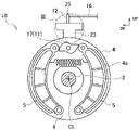
- FIG. 3 is a rear view showing a state inside the gear case in the portion III of FIG.
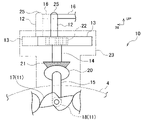
- FIG. 4 is a schematic view of FIG. 1 as viewed from the direction of arrow IV, showing the internal state of the gear case.
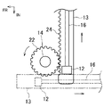
- FIG. 5 is a schematic view of FIG. 4 as viewed from the direction of arrow V.
- FIG. 6 is a side view showing another modified example of the connection state between the first shaft member and the camshaft.
- FR indicates the front of the vehicle
- UP indicates the upper side
- IN indicates the inside in the vehicle width direction.
- the front-rear direction means the front-rear direction of the vehicle
- the left-right direction means the left-right direction in a state of facing the front of the vehicle.
- the drum brake device 10 As shown in FIGS. 1 and 2, the drum brake device 10 according to the present embodiment is applied to, for example, a center brake which is a parking brake of a vehicle 1, and a propeller shaft extending in the front-rear direction behind the transmission 2 and the transmission 2. It is provided at the connecting portion with 3.
- a center brake which is a parking brake of a vehicle 1
- a propeller shaft extending in the front-rear direction behind the transmission 2 and the transmission 2. It is provided at the connecting portion with 3.
- the drum brake device 10 on the inner peripheral surface 4a of the drum 4 that can rotate around the rotation axis CL (axis center CL) extending in the front-rear direction (predetermined direction) (in this embodiment, it can rotate together with the propeller shaft 3).
- the rotation of the drum 4 is braked by pressing a pair of brake shoes 5.
- the pair of brake shoes 5 are arranged inside the radial direction of the drum 4 (the direction orthogonal to the rotation axis CL; hereinafter referred to as the "drum radial direction"), and expand toward the inner peripheral surface 4a of the drum 4. It is possible to be supported by the backing plate 6.
- the pair of brake shoes 5 are formed in an arc shape, one end side thereof (lower end side in the present embodiment) is rotatably supported by the backing plate 6, and the other end side (in the present embodiment). , Upper end side) can be tilted in the vehicle width direction.
- the drum brake device 10 is fixed to a cam member 11 capable of expanding a pair of brake shoes 5, a lever 12 for operating the cam member 11, and a lever 12.
- a brake cable for operating the slide member 13 the first shaft member 14 connected to the slide member 13, the second shaft member 15 provided between the first shaft member 14 and the cam member 11, and the lever 12. 16 and.
- the cam member 11 is a mechanism for expanding the pair of brake shoes 5, and is between the ends of the pair of brake shoes 5 on the other end side. Arranged and rotatably supported by the backing plate 6.
- the cam member 11 has a cam 17 arranged between the ends of the pair of brake shoes 5 on the other end side, and a cam shaft 18 extending linearly forward from the cam 17.
- the cam 17 is integrally provided on the camshaft 18 by being fixed to the rear end portion of the camshaft 18, and rotates with the rotation of the camshaft 18.
- the cam 17 is formed into, for example, an S shape, and by rotating, the pair of brake shoes 5 can be expanded to both sides in the vehicle width direction.
- the camshaft 18 is a shaft extending in the front-rear direction, and extends forward from the cam 17 (one side in the predetermined direction). That is, the camshaft 18 and the cam 17 of the cam member 11 are rotatably supported by the backing plate 6 about an axis extending in the front-rear direction.
- the predetermined direction is not limited to the direction parallel to the rotation axis CL of the drum 4, but also includes the direction inclined with respect to the rotation axis CL.
- the cam 17 and the camshaft 18 are integrally provided by fixing the cam 17 and the camshaft 18 to each other, but the cam 17 and the camshaft 18 may be integrally molded. ..
- a second shaft member 15 is connected to the front end (one end) of the camshaft 18 by a universal joint (universal joint) 19.
- the second shaft member 15 is a shaft member that extends linearly from the front end portion of the camshaft 18 to the front upper side (one side in the predetermined direction and the outside in the drum radial direction) and is rotatable together with the camshaft 18. It is tilted with respect to the rotation axis CL of the drum 4.
- the second shaft member 15 is arranged in a gear case 23 fixedly provided to the backing plate 6, and is rotatably supported on the gear case 23 side.
- a bevel gear 20 is integrally provided at the upper end of the second shaft member 15.
- the universal joint 19 is a joint that rotatably connects two members (camshaft 18 and second shaft member 15) in a state of being angled to each other.
- the first shaft member 14 is a rotatable shaft member that linearly extends upward from the bevel gear 20 at the upper end of the second shaft member 15, and includes the bevel gear 21 on the lower end side and the pinion gear 22 on the upper end side.
- the first shaft member 14 is arranged in the gear case 23 and is rotatably supported on the gear case 23 side.
- the bevel gear 21 on the lower end side of the first shaft member 14 is engaged with the bevel gear 20 of the second shaft member 15 from above. That is, the front end portion of the camshaft 18 of the cam member 11 and the lower end portion of the first shaft member 14 are such that the camshaft 18 is rotated by the rotation of the first shaft member 14 (in the present embodiment, the second shaft member 15). Be connected (via).
- the first shaft member 14 extends in the vertical direction (in the present embodiment, substantially in the vertical direction).
- the pinion gear 22 on the upper end side of the first shaft member 14 is engaged with the rack gear 24 described later of the slide member 13.
- the slide member 13 is a rod-shaped member that extends linearly in the vehicle width direction, has a rack gear 24 on one side (front side in this embodiment) in the front-rear direction, is arranged in the gear case 23, and is a vehicle. It is supported on the gear case 23 side so that it can slide and move in the width direction.
- the slide member 13 is arranged behind the pinion gear 22 of the first shaft member 14, and the rack gear 24 on the front side engages the pinion gear 22 of the first shaft member 14 from the rear.
- the lever 12 is fixed to the slide member 13 and extends upward from the upper surface of the slide member 13. In this embodiment, the lever 12 extends substantially in the vertical direction.
- the upper end portion 25 of the lever 12 is arranged above the drum 4 and the backing plate 6.
- the lever 12 slides between the normal position located on the left side (the position shown by the alternate long and short dash line in FIG. 3) and the used position located on the right side (the position shown by the solid line in FIG. 3). It is movable.
- the lever 12 is arranged in the normal position, and when the parking brake is used, the lever 12 is moved from the normal position to the used position. That is, in FIG. 3, the state when the parking brake is used is shown by a solid line.
- the brake cable 16 is connected to the lever 12 and extends in the vehicle width direction.
- one end of the brake cable 16 is connected to the upper end 25 of the lever 12.
- the other end of the brake cable 16 is connected to a brake actuator (not shown).
- the brake actuator is arranged on one side (on the right side in this embodiment) of the lever 12 in the vehicle width direction.
- the brake actuator when the parking brake is used, the brake actuator is electrically or mechanically operated to set the brake cable 16 on one side in the vehicle width direction (in the present embodiment). , Right side) and slide the lever 12 to the right side to move it from the normal position to the used position.
- the slide member 13 slides to the right together with the lever 12 and rotates the first shaft member 14.
- the camshaft 18 rotates via the second shaft member 15, and the cam 17 rotates accordingly.
- the cam 17 rotates to expand the pair of brake shoes 5 toward the inner peripheral surface 4a side of the drum 4.
- the pair of brake shoes 5 is pressed against the inner peripheral surface 4a of the drum 4, the rotation of the drum 4 is restricted, and the rotation of the propeller shaft 3 is restricted.
- the lever 12 is fixed to the slide member 13, and the slide member 13 is provided so as to be slidable in a direction intersecting with the first shaft member 14 (in the vehicle width direction in the present embodiment). Then, the brake cable 16 connected to the lever 12 extends from the lever 12 along the slide direction (vehicle width direction) of the slide member 13. Therefore, since the direction in which the lever 12 is pulled by the brake cable 16 and the moving direction of the lever 12 and the slide member 13 are the same, it is possible to suppress a change in the angle of the brake cable 16 with respect to the lever 12 while the lever 12 is moving. It is possible to suppress the change in force from the brake cable 16 to the lever 12.
- the angle of the brake cable 16 with respect to the lever changes while the lever is tilted, so that the force from the brake cable 16 to the lever is applied.
- the change in the force from the brake cable 16 to the lever 12 can be suppressed.
- the second shaft member 15 extends linearly from the front end portion of the camshaft 18 to the front and upper side, it is possible to suppress the protrusion of the camshaft 18 to the front.
- FIG. 6 unlike the case where the camshaft 18 is extended forward and connected to the first shaft member 14, it is possible to suppress the protrusion of the camshaft 18 forward. Therefore, since it is possible to suppress the protrusion of the front transmission 2 toward the transmission case 2a, it is not necessary to form a recess as shown by the alternate long and short dash line in FIG. 4, and the transmission case 2a due to the recess does not have to be formed. It is possible to avoid thinning, and it becomes easy to secure the rigidity of the transmission case 2a.
- the lever 12 is extended upward from the upper surface of the slide member 13, but the present invention is not limited to this.
- the lever 12 may be fixed to the slide member 13, and may be extended forward from the front surface of the slide member 13, for example.
- the brake cable 16 is connected to the upper end portion 25 of the lever 12, but the present invention is not limited to this, and the brake cable 16 may be connected to a position other than the upper end portion 25 of the lever 12.
- the slide movement direction of the slide member 13 is set to the vehicle width direction, but the present invention is not limited to this, and for example, as shown by the two-dot chain line in FIG. 5, the slide member 13 slides and moves.
- the direction may be the front-back direction.
- the brake cable 16 may be extended in the front-rear direction.
- the first shaft member 14 is extended along a substantially vertical direction, but the present invention is not limited to this, as long as it extends outward from the end on the camshaft 18 side in the radial direction of the drum. good.
- the first shaft member 14 may be inclined upward (outside in the drum radial direction) from the lower end portion on the camshaft 18 side in the vertical direction and extended.
- the lower end side of the pair of brake shoes 5 is rotatably supported by the backing plate 6, and the cam member 11 is arranged between the upper end portions (the other ends) of the pair of brake shoes 5.
- the positions of the other ends of the pair of brake shoes 5 and the cam member 11 are not limited to the upper side, and can be arranged at any position in the circumferential direction of the drum 4. Regardless of which position in the circumferential direction of the drum 4 the cam member 11 is arranged, the first shaft member 14 extends outward in the drum radial direction from the end portion of the cam member 11 on the camshaft 18 side.
- first shaft member 14 and the second shaft member 15 are rotatably connected by two bevel gears 20 and 21 in a state of being angled to each other, but the present invention is limited to this.
- a universal joint universal joint
- the second shaft member 15 and the camshaft 18 are rotatably connected by a universal joint 19 in a state of being angled to each other, but the present invention is not limited to this, and for example, 2 Two bevel gears may be rotatably connected to each other at an angle.
- the second shaft member 15 is arranged between the first shaft member 14 and the camshaft 18, and is the inner end portion (lower end portion in the present embodiment) of the first shaft member 14 in the drum radial direction and the camshaft.
- One end of 18 (the front end in this embodiment) may be connected so that the camshaft 18 rotates due to the rotation of the first shaft member 14.
- the second shaft member 15 is provided between the first shaft member 14 and the camshaft 18, but the second shaft member 15 is not provided and the first shaft member 14 is provided in the drum radial direction.
- the inner end portion and one end portion of the camshaft 18 may be connected.
- a bevel gear 31 is provided at the inner end portion (lower end portion in FIG. 6) of the first shaft member 14 in the drum radial direction, and one end portion (front end portion in FIG. 6) of the camshaft 18 is provided.
- the inner end portion of the first shaft member 14 in the drum radial direction and one end portion of the camshaft 18 are rotated by the rotation of the first shaft member 14.
- the camshaft 18 may be connected so as to rotate.
- the drum brake device 10 according to the present disclosure is applied to the center brake of the vehicle 1, but the present invention is not limited to this.
- the vehicle drum brake device according to the present disclosure can be widely applied to various vehicles.
Landscapes
- Engineering & Computer Science (AREA)
- General Engineering & Computer Science (AREA)
- Mechanical Engineering (AREA)
- Transportation (AREA)
- Braking Arrangements (AREA)
- Braking Systems And Boosters (AREA)
Abstract
カム部材11は、カム17と、カム17から前方へ延びるカムシャフト18とを有する。第2軸部材15は、カムシャフト18の前端部から前上方へ延びる。第1軸部材14は、第2軸部材15の上端部側から上方へ延び、上端側にピニオンギア22を有する。カムシャフト18の前端部と第1軸部材14の下端部とは、第1軸部材14の回転によってカムシャフト18が回転するように、第2軸部材15を介して接続される。スライド部材13は、前面側にラックギアを有し、車幅方向へスライド移動可能にギアケース23側に支持される。スライド部材13のラックギアは、第1軸部材14のピニオンギア22に後方から係合する。レバー12は、スライド部材13に対して固定される。ブレーキケーブル16は、レバー12に接続されて車幅方向に延びる。
Description
本開示は、車両のドラムブレーキ装置に関する。
特許文献1には、トラック等の大型車両の駐車専用ブレーキであるセンターブレーキに用いられるドラムブレーキが記載されている。このドラムブレーキのブレーキシューの一端部は、シューリターンスプリングの付勢力に従って、バッキングプレート上に固定されたカム部材の側面にそれぞれ当接させられるようになっている。カム部材は、軸部と、その軸部の一端側のカム部とを備えたT字状を成し、そのカム部がブレーキシューのシューウェブ間に位置する。軸部の他端には、レバーが軸部の軸心回りの相対回動不能に取り付けられている。ドラムブレーキは、レバーのカム部材とは反対側に位置する端部に連結されたブレーキケーブルが引張られることにより、レバーが回動させられると、カム部材がその軸部の軸心回りにおいて回動させられる。これにより、ブレーキシューが回転ドラムの内周面にそれぞれ押し付けられて制動が行われる。
特許文献1に記載のドラムブレーキでは、レバーの端部に連結されたブレーキケーブルを引っ張ることにより、レバーがカム部材の軸部を軸として回動する。このように、レバーの端部が円弧状に回動するので、レバーの回動時にはレバーに対するブレーキケーブルの角度が変化してしまい、ブレーキケーブルからレバーへの力を一定に保つことが難しい。
そこで、本開示は、ブレーキケーブルからレバーへの力の変化を抑えることが可能な車両のドラムブレーキ装置の提供を目的とする。
上記課題を解決するため、本開示の第1の態様は、所定方向に延びる回転軸を中心として回転可能なドラムのドラム径方向の内側に1対のブレーキシューを有する車両のドラムブレーキ装置であって、カム部材と第1軸部材とスライド部材とレバーとブレーキケーブルとを備える。カム部材は、1対のブレーキシューの間に配置されるカムと、カムに一体的に設けられてカムから上記所定方向の一側へ直線状に延びるカムシャフトとを有し、カムシャフトを軸としたカムの回転によって1対のブレーキシューをドラムの内周面側へ拡開させる。第1軸部材は、カム部材のカムシャフトからドラム径方向の外側へ離間した位置に配置されるピニオンギアを有し、ピニオンギアからカムシャフト側へ直線状に延びる。スライド部材は、第1軸部材のピニオンギアに係合するラックギアを有し、第1軸部材と交叉する方向にスライド移動可能に設けられる。レバーは、スライド部材に対して固定される。ブレーキケーブルは、レバーに接続されてレバーからスライド部材のスライド方向に沿って延びる。カム部材のカムシャフトの上記一側の一端部と第1軸部材のドラム径方向の内側の内端部とは、第1軸部材の回転によってカムシャフトが回転するように接続される。
上記構成では、スライド部材のラックギアが、第1軸部材のピニオンギアに係合し、カム部材のカムシャフトの一端部と第1軸部材の内端部とが、第1軸部材の回転によってカムシャフトが回転するように接続される。このため、スライド部材がスライド移動すると、第1軸部材が回転し、第1軸部材の回転によってカムシャフトが回転する。これにより、カムシャフトを軸としたカムの回転によって1対のブレーキシューがドラムの内周面側へ拡開する。
レバーは、スライド部材に対して固定され、スライド部材は、第1軸部材と交叉する方向にスライド移動可能に設けられる。そして、レバーに接続されるブレーキケーブルは、レバーからスライド部材のスライド方向に沿って延びる。このため、ブレーキケーブルによるレバーを引く方向と、レバー及びスライド部材の移動方向とが同じであるので、レバーの移動中にレバーに対するブレーキケーブルの角度の変化を抑えることができ、ブレーキケーブルからレバーへの力の変化を抑えることができる。
本開示の第2の態様は上記第1の態様の車両のドラムブレーキ装置であって、第2軸部材を備える。第2軸部材は、カム部材のカムシャフトと第1軸部材との間に配置されて、カムシャフトの上記一端部と第1軸部材の内端部とを、第1軸部材の回転によってカムシャフトが回転するように接続する。第2軸部材は、カムシャフトの上記一端部から上記所定方向の上記一側且つドラム径方向の外側へ直線状に延びて、ドラムの回転軸に対して傾斜する。
上記構成では、カム部材のカムシャフトと第1軸部材との間に配置される第2軸部材が、カムシャフトの一端部から上記所定方向の上記一側且つドラム径方向の外側へ直線状に延びるので、上記所定方向の上記一側へのカムシャフトの突出を抑えることができる。例えば、ドラムブレーキ装置をミッションケースの後方に接続されるセンターブレーキに適用した場合には、前方(上記所定方向の上記一側)のミッションケース側へのカムシャフトの突出を抑えることができる。
本開示の第3の態様は、上記第2の態様の車両のドラムブレーキ装置であって、第1軸部材は、内端部に第1傘歯車を有する。第2軸部材の第1端部は、カムシャフトの一端部と、ユニバーサルジョイントによって接続される。第2軸部材は、第1端部と反対側である第2端部に、第2傘歯車を有する。第1傘歯車が第2傘歯車に係合する。
本開示によれば、ブレーキケーブルからレバーへの力の変化を抑えることができる。
以下、本開示の一実施形態を図面に基づいて説明する。なお、各図において、FRは車両の前方を、UPは上方を、INは車幅方向内側をそれぞれ示す。また、以下の説明において、前後方向は車両の前後方向を意味し、左右方向は車両前方を向いた状態での左右方向を意味する。
図1及び図2に示すように、本実施形態に係るドラムブレーキ装置10は、例えば、車両1のパーキングブレーキであるセンターブレーキに適用され、トランスミッション2とトランスミッション2の後方で前後方向に延びるプロペラシャフト3との連結部分に設けられる。ドラムブレーキ装置10では、前後方向(所定方向)に延びる回転軸CL(軸心CL)を中心として回転可能な(本実施形態では、プロペラシャフト3と共に回転可能な)ドラム4の内周面4aに1対のブレーキシュー5を押し当てることによってドラム4の回転を制動する。1対のブレーキシュー5は、ドラム4の径方向(回転軸CLと直交する方向。以下、「ドラム径方向」という。)の内側に配置され、ドラム4の内周面4aへ向かって拡開可能にバッキングプレート6に支持される。本実施形態では、1対のブレーキシュー5は、円弧状に形成され、その一端側(本実施形態では、下端側)がバッキングプレート6に回転可能に支持され、他端側(本実施形態では、上端側)が車幅方向に傾動可能となっている。
図1~図5に示すように、ドラムブレーキ装置10は、1対のブレーキシュー5を拡開可能なカム部材11と、カム部材11を操作するためのレバー12と、レバー12に固定されるスライド部材13と、スライド部材13に接続される第1軸部材14と、第1軸部材14とカム部材11との間に設けられる第2軸部材15と、レバー12を操作するためのブレーキケーブル16とを備える。
図2~図4に示すように、カム部材11は、1対のブレーキシュー5を拡開させるための機構であって、1対のブレーキシュー5の上記他端側の端部同士の間に配置され、バッキングプレート6に回転可能に支持される。カム部材11は、1対のブレーキシュー5の上記他端側の端部同士の間に配置されるカム17と、カム17から前方へ直線状に延びるカムシャフト18とを有する。カム17は、カムシャフト18の後端部に固定されることによってカムシャフト18に一体的に設けられ、カムシャフト18の回転とともに回転する。カム17は、例えばS形状に成形され、回転することによって、1対のブレーキシュー5を車幅方向両側へ拡開させることが可能である。カムシャフト18は、前後方向に延びるシャフトであって、カム17から前方(上記所定方向の一側)へ延びる。すなわち、カム部材11のカムシャフト18及びカム17は、前後方向に延びる軸を中心として回転可能にバッキングプレート6に支持される。なお、上記所定方向とは、ドラム4の回転軸CLと平行な方向に限定されるものではなく、回転軸CLに対して傾斜している方向も含む。また、本実施形態では、カム17とカムシャフト18とを互いに固定することによって、カム17とカムシャフト18とを一体的に設けたが、カム17とカムシャフト18とを一体成形してもよい。
カムシャフト18の前端部(一端部)には、第2軸部材15がユニバーサルジョイント(自在継手)19によって接続される。第2軸部材15は、カムシャフト18の前端部から前上方(上記所定方向の一側且つドラム径方向の外側)へ直線状に延びて、カムシャフト18とともに回転可能な軸部材であって、ドラム4の回転軸CLに対して傾斜する。第2軸部材15は、バッキングプレート6に対して固定的に設けられたギアケース23内に配置され、ギアケース23側に回転可能に支持される。第2軸部材15の上端部には、傘歯車20が一体的に設けられる。なお、ユニバーサルジョイント19とは、2つの部材(カムシャフト18及び第2軸部材15)を互いに角度がついた状態で回転可能に接続する継手である。
第1軸部材14は、第2軸部材15の上端部の傘歯車20から上方へ直線状に延びる回転可能な軸部材であって、下端側の傘歯車21と、上端側のピニオンギア22とを有する。第1軸部材14は、ギアケース23内に配置され、ギアケース23側に回転可能に支持される。第1軸部材14の下端側の傘歯車21は、第2軸部材15の傘歯車20に上方から係合している。すなわち、カム部材11のカムシャフト18の前端部と第1軸部材14の下端部とは、第1軸部材14の回転によってカムシャフト18が回転するように(本実施形態では第2軸部材15を介して)接続される。第1軸部材14は、上下方向(本実施形態では、略鉛直方向に沿って)に延びる。第1軸部材14の上端側のピニオンギア22は、スライド部材13の後述するラックギア24に係合している。
スライド部材13は、車幅方向に直線状に延びる棒状の部材であって、前後方向の一面側(本実施形態では、前面側)にラックギア24を有し、ギアケース23内に配置され、車幅方向へスライド移動可能にギアケース23側に支持される。スライド部材13は、第1軸部材14のピニオンギア22の後方に配置され、前面側のラックギア24が第1軸部材14のピニオンギア22に後方から係合する。
レバー12は、スライド部材13に対して固定され、スライド部材13の上面から上方へ延びる。本実施形態では、レバー12は、略鉛直方向に沿って延びる。レバー12の上端部25は、ドラム4及びバッキングプレート6よりも上方に配置される。本実施形態では、レバー12は、左側に位置する通常位置(図3に二点鎖線で図示する位置)と、右側に位置する使用位置(図3に実線で図示する位置)との間をスライド移動可能である。パーキングブレーキ非使用時には、レバー12を通常位置に配置しておき、パーキングブレーキ使用時には、レバー12を通常位置から使用位置に移動させる。すなわち、図3には、パーキングブレーキ使用時の状態が実線で図示されている。
ブレーキケーブル16は、レバー12に接続されて車幅方向に延びる。本実施形態では、ブレーキケーブル16の一端は、レバー12の上端部25に接続される。ブレーキケーブル16の他端は、図示しないブレーキアクチュエータに接続される。ブレーキアクチュエータは、レバー12の車幅方向の一側(本実施形態では、右側)に配置される。
上記のように構成されたドラムブレーキ装置10では、パーキングブレーキを使用する際には、電気的または機械的にブレーキアクチュエータを作動して、ブレーキケーブル16を車幅方向の一側(本実施形態では、右側)へ引いて、レバー12を右側へスライド移動させて通常位置から使用位置に移動させる。レバー12を通常位置から使用位置へ移動させると、スライド部材13がレバー12とともに右側へスライド移動し、第1軸部材14を回転させる。第1軸部材14が回転すると、第2軸部材15を介してカムシャフト18が回転し、これに伴ってカム17が回転する。カム17は、回転することによって1対のブレーキシュー5をドラム4の内周面4a側へ拡開させる。これにより、1対のブレーキシュー5がドラム4の内周面4aに押し付けられ、ドラム4の回転が規制され、プロペラシャフト3の回転が規制される。
レバー12は、スライド部材13に対して固定され、スライド部材13は、第1軸部材14と交叉する方向(本実施形態で車幅方向)にスライド移動可能に設けられる。そして、レバー12に接続されるブレーキケーブル16は、レバー12からスライド部材13のスライド方向(車幅方向)に沿って延びる。このため、ブレーキケーブル16によるレバー12を引く方向と、レバー12及びスライド部材13の移動方向とが同じであるので、レバー12の移動中にレバー12に対するブレーキケーブル16の角度の変化を抑えることができ、ブレーキケーブル16からレバー12への力の変化を抑えることができる。例えば、カムシャフト18を軸としてドラム4の周方向に傾動するレバーを設けた場合には、レバーの傾動中にレバーに対するブレーキケーブル16の角度が変化するので、ブレーキケーブル16からレバーへの力の変化が発生するが、本実施形態によれば、ブレーキケーブル16からレバー12への力の変化を抑えることができる。
また、第2軸部材15は、カムシャフト18の前端部から前上方へ直線状に延びるので、前方へのカムシャフト18の突出を抑えることができる。例えば、図6に示すように、カムシャフト18を前方へ延ばして第1軸部材14に接続する場合とは異なり、前方へのカムシャフト18の突出を抑えることができる。このため、前方のトランスミッション2のミッションケース2a側への突出を抑えることができるので、図4に一点鎖線で示すような凹みをミッションケース2aに成形しなくてもよく、凹みによるミッションケース2aの薄肉化を回避することができ、ミッションケース2aの剛性を確保しやすくなる。
なお、本実施形態では、レバー12を、スライド部材13の上面から上方へ延ばしたが、これに限定されるものではない。レバー12は、スライド部材13に対して固定されていればよく、例えば、スライド部材13の前面から前方へ延ばしてもよい。
また、本実施形態では、ブレーキケーブル16を、レバー12の上端部25に接続したが、これに限定されるものではなく、レバー12の上端部25以外の他の位置に接続してもよい。
また、本実施形態では、スライド部材13のスライド移動方向を車幅方向としたが、これに限定されるものではなく、例えば、図5に二点鎖線で示すように、スライド部材13のスライド移動方向を前後方向としてもよい。この場合、ブレーキケーブル16を前後方向に延ばしてもよい。
また、本実施形態では、第1軸部材14を略鉛直方向に沿って延ばしたが、これに限定されるものではなく、カムシャフト18側の端部からドラム径方向の外側へ延びていればよい。例えば、第1軸部材14を、カムシャフト18側の下端部から上方(ドラム径方向の外側)へ鉛直方向に対して傾斜して延ばしてもよい。
また、本実施形態では、1対のブレーキシュー5の下端側をバッキングプレート6に回転可能に支持し、1対のブレーキシュー5の上端部(他端)同士の間にカム部材11を配置したが、1対のブレーキシュー5の他端及びカム部材11の配置位置は、上側に限定されるものではなく、ドラム4の周方向の任意の位置に配置することができる。なお、カム部材11をドラム4の周方向のいずれの位置に配置しても、第1軸部材14は、カム部材11のカムシャフト18側の端部からドラム径方向の外側へ延びる。
また、本実施形態では、第1軸部材14と第2軸部材15とを、2つの傘歯車20,21によって、互いに角度がついた状態で回転可能に接続したが、これに限定されるものではなく、例えば、ユニバーサルジョイント(自在継手)によって、互いに角度がついた状態で回転可能に接続してもよい。また、本実施形態では、第2軸部材15とカムシャフト18とを、ユニバーサルジョイント19によって、互いに角度がついた状態で回転可能に接続したが、これに限定されるものではなく、例えば、2つの傘歯車によって、互いに角度がついた状態で回転可能に接続してもよい。すなわち、第2軸部材15は、第1軸部材14とカムシャフト18との間に配置されて、第1軸部材14のドラム径方向の内端部(本実施形態では下端部)とカムシャフト18の一端部(本実施形態では前端部)とを、第1軸部材14の回転によってカムシャフト18が回転するように接続していればよい。
また、本実施形態では、第1軸部材14とカムシャフト18との間に第2軸部材15を設けたが、第2軸部材15を設けることなく、第1軸部材14のドラム径方向の内端部とカムシャフト18の一端部とを接続してもよい。例えば、図6に示すように、第1軸部材14のドラム径方向の内端部(図6では下端部)に傘歯車31を設け、カムシャフト18の一端部(図6では前端部)に傘歯車32を設け、両傘歯車31,32を係合させることによって、第1軸部材14のドラム径方向の内端部とカムシャフト18の一端部とを、第1軸部材14の回転によってカムシャフト18が回転するように接続してもよい。
以上、本発明について、上記実施形態に基づいて説明を行ったが、本発明は上記実施形態の内容に限定されるものではなく、当然に本発明を逸脱しない範囲で適宜変更が可能である。すなわち、この実施形態に基づいて当業者等によりなされる他の実施形態、実施例および運用技術等は全て本発明の範疇に含まれることは勿論である。
例えば、上記実施形態では、本開示に係るドラムブレーキ装置10を、車両1のセンターブレーキに適用したが、これに限定されるものではない。
本出願は、2020年9月28日付で出願された日本国特許出願(特願2020-162662)に基づくものであり、その内容はここに参照として取り込まれる。
本開示に係る車両のドラムブレーキ装置は、様々な車両に広く適用することができる。
1:車両
4:ドラム
5:1対のブレーキシュー
10:ドラムブレーキ装置
11:カム部材
12:レバー
13:スライド部材
14:第1軸部材
15:第2軸部材
16:ブレーキケーブル
17:カム
18:カムシャフト
22:ピニオンギア
24:ラックギア
4:ドラム
5:1対のブレーキシュー
10:ドラムブレーキ装置
11:カム部材
12:レバー
13:スライド部材
14:第1軸部材
15:第2軸部材
16:ブレーキケーブル
17:カム
18:カムシャフト
22:ピニオンギア
24:ラックギア
Claims (3)
- 所定方向に延びる回転軸を中心として回転可能なドラムのドラム径方向の内側に1対のブレーキシューを有する車両のドラムブレーキ装置であって、
前記1対のブレーキシューの間に配置されるカムと、前記カムに一体的に設けられて前記カムから前記所定方向の一側へ直線状に延びるカムシャフトとを有し、前記カムシャフトを軸とした前記カムの回転によって前記1対のブレーキシューを前記ドラムの内周面側へ拡開させるカム部材と、
前記カム部材の前記カムシャフトから前記ドラム径方向の外側へ離間した位置に配置されるピニオンギアを有し、前記ピニオンギアから前記カムシャフト側へ直線状に延びる第1軸部材と、
前記第1軸部材の前記ピニオンギアに係合するラックギアを有し、前記第1軸部材と交叉する方向にスライド移動可能に設けられるスライド部材と、
前記スライド部材に対して固定されるレバーと、
前記レバーに接続されて前記レバーから前記スライド部材のスライド方向に沿って延びるブレーキケーブルと、を備え、
前記カム部材の前記カムシャフトの前記一側の一端部と前記第1軸部材の前記ドラム径方向の内側の内端部とは、前記第1軸部材の回転によって前記カムシャフトが回転するように接続される
ことを特徴とする車両のドラムブレーキ装置。 - 前記カム部材の前記カムシャフトと前記第1軸部材との間に配置されて、前記カムシャフトの前記一端部と前記第1軸部材の前記内端部とを、前記第1軸部材の回転によって前記カムシャフトが回転するように接続する第2軸部材をさらに備え、
前記第2軸部材は、前記カムシャフトの前記一端部から前記所定方向の前記一側且つ前記ドラム径方向の外側へ直線状に延びて、前記ドラムの前記回転軸に対して傾斜する
ことを特徴とする、請求項1に記載の車両のドラムブレーキ装置。 - 前記第1軸部材は前記内端部に第1傘歯車を有し、
前記第2軸部材の第1端部は、前記カムシャフトの前記一端部とユニバーサルジョイントによって接続され、
前記第2軸部材は、前記第1端部と反対側である第2端部に、第2傘歯車を有し、
前記第1傘歯車が前記第2傘歯車に係合する
ことを特徴とする、請求項2に記載の車両のドラムブレーキ装置。
Applications Claiming Priority (2)
| Application Number | Priority Date | Filing Date | Title |
|---|---|---|---|
| JP2020-162662 | 2020-09-28 | ||
| JP2020162662A JP2022055207A (ja) | 2020-09-28 | 2020-09-28 | 車両のドラムブレーキ装置 |
Publications (1)
| Publication Number | Publication Date |
|---|---|
| WO2022065071A1 true WO2022065071A1 (ja) | 2022-03-31 |
Family
ID=80846570
Family Applications (1)
| Application Number | Title | Priority Date | Filing Date |
|---|---|---|---|
| PCT/JP2021/033263 Ceased WO2022065071A1 (ja) | 2020-09-28 | 2021-09-10 | 車両のドラムブレーキ装置 |
Country Status (2)
| Country | Link |
|---|---|
| JP (1) | JP2022055207A (ja) |
| WO (1) | WO2022065071A1 (ja) |
Citations (5)
| Publication number | Priority date | Publication date | Assignee | Title |
|---|---|---|---|---|
| JPH10159878A (ja) * | 1996-11-26 | 1998-06-16 | Nisshinbo Ind Inc | ドラムブレーキ装置 |
| JP2009056957A (ja) * | 2007-08-31 | 2009-03-19 | Honda Motor Co Ltd | インホイールモータ駆動装置 |
| JP2011084179A (ja) * | 2009-10-16 | 2011-04-28 | Mitsuba Corp | ホイールモータ |
| CN207131763U (zh) * | 2017-09-08 | 2018-03-23 | 霸州市华诚汽车制动器有限公司 | 一种驻车制动器 |
| DE102017220796A1 (de) * | 2017-11-21 | 2019-05-23 | Brose Fahrzeugteile Gmbh & Co. Kommanditgesellschaft, Bamberg | Schalteinrichtung zum Herstellen einer Wirkverbindung zwischen zwei Getriebeteilen |
-
2020
- 2020-09-28 JP JP2020162662A patent/JP2022055207A/ja active Pending
-
2021
- 2021-09-10 WO PCT/JP2021/033263 patent/WO2022065071A1/ja not_active Ceased
Patent Citations (5)
| Publication number | Priority date | Publication date | Assignee | Title |
|---|---|---|---|---|
| JPH10159878A (ja) * | 1996-11-26 | 1998-06-16 | Nisshinbo Ind Inc | ドラムブレーキ装置 |
| JP2009056957A (ja) * | 2007-08-31 | 2009-03-19 | Honda Motor Co Ltd | インホイールモータ駆動装置 |
| JP2011084179A (ja) * | 2009-10-16 | 2011-04-28 | Mitsuba Corp | ホイールモータ |
| CN207131763U (zh) * | 2017-09-08 | 2018-03-23 | 霸州市华诚汽车制动器有限公司 | 一种驻车制动器 |
| DE102017220796A1 (de) * | 2017-11-21 | 2019-05-23 | Brose Fahrzeugteile Gmbh & Co. Kommanditgesellschaft, Bamberg | Schalteinrichtung zum Herstellen einer Wirkverbindung zwischen zwei Getriebeteilen |
Also Published As
| Publication number | Publication date |
|---|---|
| JP2022055207A (ja) | 2022-04-07 |
Similar Documents
| Publication | Publication Date | Title |
|---|---|---|
| EP2540579B1 (en) | Vehicle pedal system | |
| US20120205209A1 (en) | Drum brake type parking brake apparatus | |
| JP2022055207A (ja) | 車両のドラムブレーキ装置 | |
| US20110127130A1 (en) | Mechanical drum brake | |
| JP2005088755A (ja) | ステアリングコラム装置 | |
| JP2017057909A (ja) | 電動パーキングブレーキ装置 | |
| US8333267B2 (en) | Vehicle disk brake | |
| JP2873772B2 (ja) | ディスクブレーキ | |
| CN114483820B (zh) | 用于车辆的鼓式制动装置 | |
| JP2005538891A (ja) | 自動車用のペダルの装着装置 | |
| WO2016093002A1 (ja) | 折り畳み式車両 | |
| JP5517861B2 (ja) | 変速機のシフトアンドセレクトシャフトアッセンブリ | |
| JP2007055281A (ja) | 走行速度操作装置 | |
| JP5126037B2 (ja) | 車両用ペダル装置 | |
| WO2022071183A1 (ja) | 車両のドラムブレーキ装置 | |
| JP5717605B2 (ja) | 電動駐車ブレーキ装置 | |
| KR102419814B1 (ko) | 전자기계식 브레이크 및 이를 구비하는 차량 | |
| WO2013035626A1 (ja) | ドラムブレーキ装置 | |
| JP2009515105A (ja) | 相互に逆向きに移動する楔要素を備えた楔式ブレーキ | |
| EP3666609B1 (en) | Working vehicle | |
| EP2676868B1 (en) | Neutral Position Locking Apparatus and Rear Wheel Steering System including the same | |
| JP2018202963A (ja) | ステアリング装置 | |
| WO2016125337A1 (ja) | 車両用ペダル装置の後退防止装置 | |
| JP6578165B2 (ja) | 作業車両 | |
| JP7136403B2 (ja) | シフト装置 |
Legal Events
| Date | Code | Title | Description |
|---|---|---|---|
| 121 | Ep: the epo has been informed by wipo that ep was designated in this application |
Ref document number: 21872202 Country of ref document: EP Kind code of ref document: A1 |
|
| NENP | Non-entry into the national phase |
Ref country code: DE |
|
| 122 | Ep: pct application non-entry in european phase |
Ref document number: 21872202 Country of ref document: EP Kind code of ref document: A1 |