WO2022064902A1 - 撮像装置及び振れ抑制方法 - Google Patents
撮像装置及び振れ抑制方法 Download PDFInfo
- Publication number
- WO2022064902A1 WO2022064902A1 PCT/JP2021/030229 JP2021030229W WO2022064902A1 WO 2022064902 A1 WO2022064902 A1 WO 2022064902A1 JP 2021030229 W JP2021030229 W JP 2021030229W WO 2022064902 A1 WO2022064902 A1 WO 2022064902A1
- Authority
- WO
- WIPO (PCT)
- Prior art keywords
- shutter unit
- frame
- image pickup
- elastic members
- shutter
- Prior art date
- Legal status (The legal status is an assumption and is not a legal conclusion. Google has not performed a legal analysis and makes no representation as to the accuracy of the status listed.)
- Ceased
Links
Images


Classifications
-
- G—PHYSICS
- G03—PHOTOGRAPHY; CINEMATOGRAPHY; ANALOGOUS TECHNIQUES USING WAVES OTHER THAN OPTICAL WAVES; ELECTROGRAPHY; HOLOGRAPHY
- G03B—APPARATUS OR ARRANGEMENTS FOR TAKING PHOTOGRAPHS OR FOR PROJECTING OR VIEWING THEM; APPARATUS OR ARRANGEMENTS EMPLOYING ANALOGOUS TECHNIQUES USING WAVES OTHER THAN OPTICAL WAVES; ACCESSORIES THEREFOR
- G03B9/00—Exposure-making shutters; Diaphragms
- G03B9/08—Shutters
- G03B9/10—Blade or disc rotating or pivoting about axis normal to its plane
- G03B9/24—Adjusting size of aperture formed by members when fully open so as to constitute a virtual diaphragm that is adjustable
-
- G—PHYSICS
- G02—OPTICS
- G02B—OPTICAL ELEMENTS, SYSTEMS OR APPARATUS
- G02B27/00—Optical systems or apparatus not provided for by any of the groups G02B1/00 - G02B26/00, G02B30/00
- G02B27/64—Imaging systems using optical elements for stabilisation of the lateral and angular position of the image
- G02B27/646—Imaging systems using optical elements for stabilisation of the lateral and angular position of the image compensating for small deviations, e.g. due to vibration or shake
-
- G—PHYSICS
- G03—PHOTOGRAPHY; CINEMATOGRAPHY; ANALOGOUS TECHNIQUES USING WAVES OTHER THAN OPTICAL WAVES; ELECTROGRAPHY; HOLOGRAPHY
- G03B—APPARATUS OR ARRANGEMENTS FOR TAKING PHOTOGRAPHS OR FOR PROJECTING OR VIEWING THEM; APPARATUS OR ARRANGEMENTS EMPLOYING ANALOGOUS TECHNIQUES USING WAVES OTHER THAN OPTICAL WAVES; ACCESSORIES THEREFOR
- G03B17/00—Details of cameras or camera bodies; Accessories therefor
- G03B17/02—Bodies
-
- G—PHYSICS
- G03—PHOTOGRAPHY; CINEMATOGRAPHY; ANALOGOUS TECHNIQUES USING WAVES OTHER THAN OPTICAL WAVES; ELECTROGRAPHY; HOLOGRAPHY
- G03B—APPARATUS OR ARRANGEMENTS FOR TAKING PHOTOGRAPHS OR FOR PROJECTING OR VIEWING THEM; APPARATUS OR ARRANGEMENTS EMPLOYING ANALOGOUS TECHNIQUES USING WAVES OTHER THAN OPTICAL WAVES; ACCESSORIES THEREFOR
- G03B5/00—Adjustment of optical system relative to image or object surface other than for focusing
-
- G—PHYSICS
- G03—PHOTOGRAPHY; CINEMATOGRAPHY; ANALOGOUS TECHNIQUES USING WAVES OTHER THAN OPTICAL WAVES; ELECTROGRAPHY; HOLOGRAPHY
- G03B—APPARATUS OR ARRANGEMENTS FOR TAKING PHOTOGRAPHS OR FOR PROJECTING OR VIEWING THEM; APPARATUS OR ARRANGEMENTS EMPLOYING ANALOGOUS TECHNIQUES USING WAVES OTHER THAN OPTICAL WAVES; ACCESSORIES THEREFOR
- G03B9/00—Exposure-making shutters; Diaphragms
- G03B9/08—Shutters
- G03B9/36—Sliding rigid plate
- G03B9/40—Double plate
-
- H—ELECTRICITY
- H04—ELECTRIC COMMUNICATION TECHNIQUE
- H04N—PICTORIAL COMMUNICATION, e.g. TELEVISION
- H04N23/00—Cameras or camera modules comprising electronic image sensors; Control thereof
- H04N23/60—Control of cameras or camera modules
- H04N23/68—Control of cameras or camera modules for stable pick-up of the scene, e.g. compensating for camera body vibrations
- H04N23/682—Vibration or motion blur correction
Definitions
- This disclosure relates to an image pickup device and a runout suppression method.
- the blur correction camera described in Japanese Patent Application Laid-Open No. 2011-107439 rotates a photographing optical system, an image sensor, a blur correction means, a photographing control unit, an image pickup main body including a shutter button and a shutter spring, and an image pickup main body. It includes a frame that dynamically supports the frame, and a support spring that is held by the frame and supports the image pickup main body.
- the image pickup device is provided in the main body of the device and has an image pickup element having an image pickup surface orthogonal to the optical axis of the light for forming an optical image, and an image pickup device for light incident on the image pickup device. It is equipped with a shutter unit that adjusts the amount.
- the shutter unit has a support member and a shutter member provided on the main body of the apparatus. The shutter member is supported by the support member and the support member, and moves in a direction orthogonal to the optical axis.
- 2020/021956 is further provided in the main body of the device, and has a camera shake correction unit for correcting the amount of camera shake by moving the image pickup element in a direction orthogonal to the optical axis, and an optical axis.
- a plurality of elastic members arranged on at least one side and the other side with respect to a virtual straight line passing through the center of gravity of the shutter unit and orthogonal to the optical axis when viewed from the optical axis direction, and in contact with the device main body and the support member. And has.
- One embodiment according to the technique of the present disclosure provides an image pickup apparatus and a vibration suppression method capable of achieving both suppression of vibration generated by operation of a shutter and holding of a position of a shutter unit with high accuracy.
- a first aspect of the technique of the present disclosure is an image pickup apparatus comprising a shutter unit having a shutter for adjusting the amount of subject light incident on an image sensor via an image pickup optical system, and the shutter unit is attached to a frame.
- the shutter unit is provided with at least three elastic members, and at least three or more elastic members are arranged on the outer periphery of the contour of the front view of the shutter unit, and the shutter unit is pressed from the frame side.
- Each of at least three or more elastic members is elastically deformed in the first direction, which is the direction in which the shutter unit is pressed from the frame side, and in the second direction, which is the direction perpendicular to the first direction.
- An image pickup device in which the first direction of each of at least three or more elastic members intersects each other at a specific point inside the contour.
- At least three or more elastic members are arranged at locations forming a polygon with each position of at least three or more elastic members as vertices, and a specific location is provided.
- the image pickup apparatus according to the first aspect which is located inside the polygon.
- a third aspect of the technique of the present disclosure is an imaging according to the second aspect, wherein the distance between adjacent vertices of a polygon is less than 180 degrees in the circumferential direction centered on a specific point in front view. It is a device.
- a fourth aspect of the technique of the present disclosure further comprises a shake correction mechanism that corrects runout by moving the image sensor in a plane perpendicular to the optical axis of the imaging optical system, and the shake correction mechanism is attached to the frame.
- the image pickup apparatus according to any one of the first to third aspects described above.
- a fifth aspect of the technique of the present disclosure is that the image pickup optical system can be attached to a frame, and the image pickup optical system corrects runout by moving the image pickup optical system in a plane perpendicular to the optical axis of the image pickup optical system.
- the image pickup device according to any one of the first to fourth aspects, which has an anti-vibration lens.
- a sixth aspect according to the technique of the present disclosure is any one of the first to fifth aspects in which the elastic force in the first direction is larger than the elastic force in the second direction for at least three or more elastic members. It is an image pickup apparatus which concerns on one aspect.
- a seventh aspect according to the technique of the present disclosure is that the shutter unit is supported from the outer peripheral side by at least three or more elastic members in a state where the shutter unit can swing against the elastic force of at least three or more elastic members.
- the image pickup apparatus according to any one of the first to sixth aspects.
- the eighth aspect according to the technique of the present disclosure is an image pickup apparatus according to any one of the first to seventh aspects, wherein the specific location is one location inside the contour.
- the ninth aspect according to the technique of the present disclosure is the image pickup apparatus according to the eighth aspect, in which one place coincides with the center of gravity of the shutter unit in a front view.
- the tenth aspect according to the technique of the present disclosure is the image pickup apparatus according to the eighth aspect, in which one place is the center of gravity of the shutter unit.
- the eleventh aspect according to the technique of the present disclosure is that the first direction of at least one elastic member among at least three or more elastic members coincides with the vertical direction when the image pickup apparatus performs imaging in a standard posture.
- the image pickup apparatus according to any one of the first to tenth aspects.
- a twelfth aspect according to the technique of the present disclosure is a state in which at least three or more elastic members are compressed in the first direction between the frame and the shutter unit at the outer periphery when the position of the shutter unit is the reference position.
- a thirteenth aspect according to the technique of the present disclosure is a twelfth aspect in which the amount of movement of the shutter unit in the vertical direction when the image pickup apparatus performs imaging in a standard posture is equal to or less than the movable amount of the shutter unit. This is the image pickup device.
- a fourteenth aspect according to the technique of the present disclosure is that the shutter unit has a rotating member, the rotating member is connected to the shutter, and the shutter is opened and closed by rotating motion, and the shutter unit is a rotating member.
- the shutter unit swings along the second direction, and the elastic force of at least three or more elastic members causes the shutter unit to swing along the second direction.
- a fifteenth aspect according to the technique of the present disclosure is an image pickup apparatus according to any one of the first to fourteenth aspects, wherein the shutter is a focal plane shutter.
- a sixteenth aspect according to the technique of the present disclosure is an image pickup apparatus according to any one of the first to fifteenth aspects, wherein at least one of at least three or more elastic members is a compression coil spring. Is.
- a seventeenth aspect according to the technique of the present disclosure is an image pickup apparatus according to any one of the first to sixteenth aspects, further comprising a holding mechanism for holding the position of an end portion of an elastic member.
- the holding mechanism has a first fastener and a first engaging member that engages with the first fastener, and the first fastener and the first engaging member. One of them is provided on one of the first ends of the frame and the elastic member, and the other of the first fastener and the first engaging member is of the frame and the first end.
- the image pickup device according to the seventeenth aspect provided on the other side.
- the holding mechanism has a second fastener and a second engaging member that engages with the second fastener, and the second fastener and the second engaging member.
- One of them is provided at one of the second ends of the shutter unit and the elastic member, and the other of the second fastener and the second engaging member is of the shutter unit and the second end. It is an image pickup apparatus which concerns on the 17th aspect or the 18th aspect provided in the other of them.
- a twentieth aspect according to the technique of the present disclosure is a first aspect further comprising a friction material which is interposed between the frame and the shutter unit and regulates the positional deviation between the frame and the shutter unit by a frictional force.
- 19 is an image pickup apparatus according to any one of the nineteenth aspects.
- a twenty-first aspect according to the technique of the present disclosure is a shutter unit made of at least three or more elastic members when the specific location is an inner predetermined range and the predetermined range is the center of gravity of the specific location.
- a 22nd aspect according to the technique of the present disclosure comprises a shutter unit having a shutter for adjusting the amount of light of a subject light incident on an image sensor via an image pickup optical system, and at least three or more elastic members.
- the shutter unit is supported by pressing the shutter unit from the frame side against the elastic member of the above, and the first direction in which each of at least three or more elastic members presses the shutter unit from the frame side.
- Each of at least three or more elastic members is elastically deformed in a second direction perpendicular to the first direction, and the first direction of each of at least three or more elastic members is contoured. It is a runout suppression method that includes crossing each other at specific points on the inside.
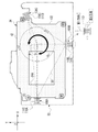
- the shutter unit is pressed by a plurality of compression coil springs from the outer periphery of the shutter unit toward the intersection on the virtual line passing through the center of gravity in the Z direction with the shutter unit attached to the front frame.
- It is a schematic bottom view which shows an example of the structure of the front side frame and the shutter unit when viewed from the bottom side of a camera.
- the shutter unit is pressed by four compression coil springs from the outer periphery of the shutter unit toward the intersection on the virtual line passing through the center of gravity in the Z direction with the shutter unit attached to the front frame.
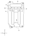
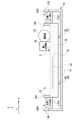
- It is a schematic rear view which shows an example of the structure of the front side frame and the shutter unit when viewed from the back side of a camera.
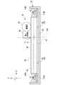
- the front side of the digital camera when the shutter unit is pressed by a plurality of compression coil springs from the outer periphery of the shutter unit toward the center of gravity with the shutter unit attached to the front frame.
- It is a schematic bottom view which shows an example of the structure of a frame and a shutter unit.
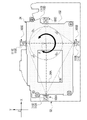
- the rear surface of the digital camera shows a mode in which the shutter unit is pressed by three compression coil springs from the outer circumference of the shutter unit toward a predetermined range including the center of gravity with the shutter unit attached to the front frame. It is a schematic rear view which shows an example of the structure of the front side frame and the shutter unit when viewed from the side.
- CPU is an abbreviation for "Central Processing Unit”.
- RAM is an abbreviation for "RandomAccessMemory”.
- NVM is an abbreviation for "Non-Volatile Memory”.
- ASIC is an abbreviation for "Application Specific Integrated Circuit”.
- PLD is an abbreviation for "Programmable Logic Device”.
- FPGA refers to the abbreviation of "Field-Programmable Gate Array”.
- CMOS is an abbreviation for "Complementary Metal Oxide Semiconductor”.
- CCD refers to the abbreviation of "Charge Coupled Device”.
- OIS is an abbreviation for "Optical Image Stabilization”.
- BIS is an abbreviation for "Body Image Stabilization”.
- QCD is an abbreviation for "Quality Cost Delivery”.
- vertical is an error generally allowed in the technical field to which the technology of the present disclosure belongs, in addition to the perfect verticality, which is contrary to the purpose of the technology of the present disclosure. It refers to the vertical in the sense that it includes an error that does not occur.
- orthogonality is an error generally allowed in the technical field to which the technique of the present disclosure belongs, in addition to the perfect orthogonality, which is contrary to the purpose of the technique of the present disclosure. It refers to orthogonality in the sense that it includes an error that does not occur.
- parallel is an error generally allowed in the technical field to which the technology of the present disclosure belongs, in addition to the perfect parallelism, which is contrary to the purpose of the technology of the present disclosure. It refers to parallelism in the sense that it includes an error that does not occur.
- identical is an error generally allowed in the technical field to which the technology of the present disclosure belongs, in addition to being completely the same, which is contrary to the purpose of the technology of the present disclosure. It refers to the same in the sense that it includes an error to the extent that it does not occur.
- the digital camera 10 is an example of an "imaging device" according to the technique of the present disclosure.
- the digital camera 10 may be a consumer digital camera, an industrial digital camera, or a military digital camera.
- Specific examples of the digital camera 10 include a digital single-lens reflex camera, a digital compact camera, a digital camera mounted on a smart device (for example, a smartphone), a surveillance camera, and the like.
- the digital camera 10 includes a camera body 12.
- a lens mount 14 is provided on the front surface of the camera body 12.
- the lens mount 14 has an opening 16.
- the opening 16 has a circular shape when the digital camera 10 is viewed from the front side.
- An interchangeable image pickup lens 18 (see FIG. 2) is detachably attached to the lens mount 14.
- the image sensor 20 is mounted on the camera body 12.
- the image sensor 20 is a CMOS image sensor.
- the image sensor 20 has an image pickup surface 20A.
- the image pickup surface 20A is arranged at a position facing the opening 16 and is exposed to the outside through the opening 16.
- the subject light indicating the subject is incident on the camera body 12 through the aperture 16 and is received by the image pickup surface 20A.
- On the imaging surface 20A a plurality of photosensitive pixels are arranged two-dimensionally. In the example shown in FIG. 1, the imaging surface 20A is formed in a rectangular shape when viewed from the front side of the digital camera 10.
- An optical image 22 is formed on the image pickup surface 20A by forming a subject light image by the image pickup lens 18.
- the CMOS image sensor 20 photoelectrically converts the subject light received by the image pickup surface 20A, and outputs an electric signal obtained by the photoelectric change as an image signal.
- the output destination of the image signal is, for example, a storage device and / a display (not shown).
- the storage device holds an image signal, and the display displays an image (an image showing a subject) based on the image signal.
- the rectangular shape of the image pickup surface 20A when viewed from the front side of the digital camera 10 is formed by two sides 20A1 which are opposite sides and two sides 20A2 which are opposite sides.
- the side 20A1 is a side in the longitudinal direction of the image pickup surface 20A
- the side 20A2 is a side in the lateral direction of the image pickup surface 20A.
- the image sensor 20 is provided in the camera body 12 so that the side 20A1 is parallel to the horizontal plane and the side 20A2 is parallel to the vertical plane.
- the posture of the digital camera 10 when the side 20A1 is parallel to the horizontal plane and the side 20A2 is parallel to the vertical plane is also referred to as a "standard posture" below.
- the definition of the standard posture is merely an example.
- the direction parallel to the side 20A1 is referred to as the X direction
- the direction parallel to the side 20A2 is referred to as the Y direction
- the front view depth direction with respect to the camera body 12 that is, the X direction and the Y direction.
- the direction perpendicular to both is called the X direction.
- a shutter unit 24 is mounted on the camera body 12.
- the shutter unit 24 is arranged between the lens mount 14 and the image sensor 20 in the Z direction.
- the shutter unit 24 has an opening 24A.
- the opening 24A is formed at a position facing the image pickup surface 20A when viewed from the Z direction.
- the opening 24A is formed to have a size enough to accommodate the imaging surface 20A when viewed from the Z direction.
- an opening formed in a rectangular shape larger than the outer contour of the image pickup surface 20A when viewed from the Z direction is shown.
- the camera body 12 includes an exterior frame 26.
- the holding frame 28 is housed in the exterior frame 26.
- the holding frame 28 is an example of a "frame" according to the technique of the present disclosure.
- the holding frame 28 is a frame for holding various devices, and is fixed to the inner wall of the exterior frame 26.
- the holding frame 28 has a lens mount 14.
- the image pickup lens 18 is attached to the lens mount 14.
- the image pickup lens 18 has an image pickup optical system 30.
- the image pickup optical system 30 includes a plurality of optical elements. Examples of the plurality of optical elements include a plurality of lenses and an aperture (not shown).
- an objective lens 30A and an anti-vibration lens 30B are shown as an example of a plurality of lenses.
- the objective lens 30A and the anti-vibration lens 30B are arranged in the order of the objective lens 30A and the anti-vibration lens 30B along the optical axis OA from the subject side to the image sensor 20 side.
- the subject light passes through the objective lens 30A and the anti-vibration lens 30B and forms an image on the image pickup surface 20A.
- the “shake” refers to a decrease in the fluctuation of the subject image obtained by forming an image on the image pickup surface 20A due to the tilt of the optical axis OA with respect to the reference axis due to vibration. ..
- the “reference axis” here refers to, for example, the optical axis OA in a state where no vibration is applied.
- Examples of the subject image include an optical image 22 (see FIG. 1) and an electronic image (not shown).
- the electronic image refers to, for example, an electronic image based on an image signal.
- the subject image changes as the positional relationship between the optical axis OA and the imaging surface 20A changes.
- the digital camera 10 is provided with an optical image stabilization mechanism 32 in order to correct the image stabilization.
- the image pickup lens 18 is equipped with an optical image stabilization mechanism 32.
- the optical image stabilization mechanism 32 includes an anti-vibration lens 30B, an actuator 34, and the like, and optically corrects the vibration by moving the anti-vibration lens 30B.
- the "correction of runout" includes not only the meaning of eliminating the runout but also the meaning of reducing the runout.
- OIS is adopted as one of the runout correction methods by the optical runout correction mechanism 32.
- the OIS refers to a method of correcting vibration by moving the vibration isolation lens 30B based on vibration data obtained by detecting vibration by a vibration sensor 38 (described later). Specifically, in the direction in which the runout is canceled, the amount of the runout is canceled in the plane perpendicular to the optical axis OA, that is, in the plane defined in the X-axis direction and the Y direction (hereinafter, also referred to as "XY plane"). The vibration is corrected by moving the anti-vibration lens 30B.
- An actuator 34 is attached to the anti-vibration lens 30B.
- the actuator 34 is a shift mechanism on which a coil motor is mounted, and by driving the coil motor, the anti-vibration lens 30B is changed in the direction perpendicular to the optical axis of the anti-vibration lens 30B.
- the shift mechanism in which the coil motor is mounted is illustrated here as the actuator 34, the technique of the present disclosure is not limited to this, and instead of the coil motor, other stepping motors, piezo elements, and the like are used.
- a drive source may be applied.
- the holding frame 28 houses an image sensor 20, a shutter unit 24, a control device 36, a vibration sensor 38, and a camera body side image stabilization mechanism 40. Further, the image sensor 20, the shutter unit 24, the control device 36, the vibration sensor 38, and the camera body side image stabilization mechanism 40 are fixed to the holding frame 28.
- the camera body side image stabilization mechanism 40 is an example of the "image stabilization mechanism" according to the technique of the present disclosure.
- the control device 36 controls the entire digital camera 10.
- the control device 36 is realized by a computer-based device having a CPU, RAM, and NVM.
- the control device 36 is not limited to the technology of the present disclosure, and the control device 36 includes an ASIC, an FPGA, and / or a PLD. It may be a device, or it may be realized by a combination of a hardware configuration and a software configuration.
- the control device 36 is connected to the image sensor 20 and controls the operation of the image sensor 20 and acquires an image signal from the image sensor 20.
- the vibration sensor 38 is a device including a gyro sensor, and detects vibration given to the digital camera 10.
- the vibration given to the digital camera 10 includes, for example, the vibration given to the digital camera 10 by the user holding the digital camera 10, and the vibration caused by the wind to the digital camera 10 installed on a support base such as a tripod. , And vibration given from the vehicle.
- the control device 36 is connected to the vibration sensor 38 and acquires the detection result by the vibration sensor 38.
- the shutter unit 24 adjusts the amount of subject light incident through the imaging optical system 30 by a focal plane shutter method.
- the shutter unit 24 includes a shutter frame 42, a front curtain 44, a rear curtain 46, and a drive device 48.
- An opening 24A is formed in the shutter frame 42.
- the shutter frame 42 accommodates and holds the front curtain 44 and the rear curtain 46, which are examples of the "focal plane shutter" according to the technique of the present disclosure.
- Each of the front curtain 44 and the rear curtain 46 includes a plurality of blades, and by operating the plurality of blades, the amount of light of the subject light incident on the image pickup optical system 30 is adjusted.
- the front curtain 44 is arranged closer to the subject than the rear curtain 46.
- the state where the front curtain 44 and the rear curtain 46 are fully opened is shown.
- the plurality of blades of the front curtain 44 are overlapped and accommodated on the lower edge portion of the shutter frame 42, and the plurality of blades of the rear curtain 46 are overlapped and accommodated on the upper edge portion of the shutter frame 42. Has been done.
- the drive device 48 includes a drive source 82 (see FIGS. 3 to 5) and a power transmission mechanism 84 (see FIGS. 3 to 5).
- An example of the drive source 82 is a solenoid.
- the drive source 82 is not limited to the solenoid, but may be a combination of a solenoid and a motor, or another type of drive source such as a motor.
- the power transmission mechanism 84 a mechanism including a plurality of gears, a link mechanism, and the like can be mentioned.
- the power transmission mechanism 84 is a mechanism for transmitting the power generated by the drive source 82 to the front curtain 44 and the rear curtain 46.
- the drive device 48 is connected to the control device 36. Specifically, the drive source 82 of the drive device 48 is connected to the control device 36, and the drive source 82 generates power under the control of the control device 36.
- the front curtain 44 and the rear curtain 46 are mechanically connected to the drive device 48.
- the drive device 48 generates power for the front curtain under the control of the control device 36, and applies the generated power for the front curtain to the front curtain 44 to selectively wind and lower the front curtain 44. Further, the drive device 48 generates power for the rear curtain under the control of the control device 36, and applies the generated power for the rear curtain to the rear curtain 46 to selectively wind and lower the rear curtain 46.
- the camera body side image stabilization mechanism 40 is a mechanism that corrects image stabilization by the BIS method.
- BIS refers to a method of correcting vibration by moving the anti-vibration lens 30B based on vibration data obtained by detecting vibration by the vibration sensor 38.
- the camera body side image stabilization mechanism 40 includes an actuator 50 in order to realize image stabilization by the BIS method.
- the actuator 50 is provided on the image sensor 20 and is fixed to the holding frame 28.
- the actuator 50 is connected to the control device 36 and operates under the control of the control device 36.
- the actuator 50 is a shift mechanism on which a coil motor is mounted, and moves the image sensor 20 by driving the coil motor according to an instruction from the control device 36.
- the control device 36 acquires the detection result by the vibration sensor 38, and controls the actuator 50 based on the acquired result, so that the amount of the vibration is canceled in the XY plane in the direction of canceling the vibration. Moves the image sensor 20 with.
- the control device 36 is also connected to the actuator 34 of the optical runout correction mechanism 32.
- the actuator 34 operates under the control of the control device 36. That is, the actuator 34 moves the anti-vibration lens 30B by driving the coil motor according to the instruction from the control device 36.
- the control device 36 acquires the detection result by the vibration sensor 38, and controls the actuator 34 based on the acquired result, so that the amount of the vibration is canceled in the direction of canceling the vibration in the XY plane.
- the anti-vibration lens 30B is moved.
- the holding frame 28 is a frame formed by combining a plurality of frames. Examples of the plurality of frames include a front side frame 52 (see FIG. 3) and a back side frame (not shown). The holding frame 28 is formed by assembling the back frame to the front frame 52.
- the front side frame 52 has a lens mount 14, and an opening 16 is formed in the lens mount 14.
- a flat surface 54 parallel to the XY plane is formed on the back surface 53 of the front frame 52.
- a side wall 56 is formed on the outer peripheral edge of the flat surface 54.
- the side wall 56 extends toward the back surface of the digital camera 10 along the Z direction, and is integrally formed with the flat surface 54.
- the side wall 56 is roughly classified into a lower side wall 56A and a left side wall 56B.
- the lower side wall 56A extends from the lower edge portion of the outer peripheral edge of the flat surface 54 when viewed from the back side of the digital camera 10 to the back side of the digital camera 10 along the Z direction.
- the left side wall 56B extends from the left edge portion of the outer peripheral edge of the flat surface 54 when viewed from the back side of the digital camera 10 to the back side of the digital camera 10 along the Z direction.
- Brackets 58, 60 and 62 are erected on the back surface 53.
- the bracket 58 is formed in a thin plate shape, and is arranged at the upper left portion when the flat surface 54 is viewed from the back side of the digital camera 10.
- the bracket 58 stands up perpendicular to the flat surface 54. In other words, the bracket 58 extends from the flat surface 54 side to the back side of the digital camera 10 along the Z direction.
- the wide surface 58A of the surface of the bracket 58 is a plane parallel to a plane defined in the Y direction and the Z direction (hereinafter, also referred to as “YZ plane”).
- the bracket 58 has a notch 58B.
- the notch 58B is formed in a wide shape with a step from the back surface side of the digital camera 10 to the central portion of the bracket 58.
- the bracket 60 is formed in a thin plate shape, and is arranged at the lower right when the flat surface 54 is viewed from the back side of the digital camera 10.
- the bracket 60 stands up perpendicular to the flat surface 54. In other words, the bracket 60 extends from the flat surface 54 side to the back side of the digital camera 10 along the Z direction.
- the wide surface 60A of the surface of the bracket 60 is a plane parallel to the plane defined in the X direction and the Z direction (hereinafter, also referred to as “XZ plane”).
- the bracket 60 has a notch 60B.
- the notch 60B is formed in a wide shape with a step from the back surface side of the digital camera 10 to the central portion of the bracket 60.
- the bracket 62 is formed in a thin plate shape, and is arranged in the upper right portion when the back 53 of the front frame 52 is viewed from the back side of the digital camera 10.
- the bracket 58 stands up perpendicular to the flat surface 54.
- the bracket 60 extends from the back surface 53 side to the back surface side of the digital camera 10 along the Z direction.
- the wide surface 62A of the surface of the bracket 62 is a flat surface that is inclined downward from the upper right portion when the rear side 53 of the front side frame 52 is viewed from the rear side of the digital camera 10 to the right side of the rear view of the digital camera 10. be.
- the bracket 62 has a notch 62B.
- the notch 62B is formed in a wide shape with a step from the back surface side of the digital camera 10 to the central portion of the bracket 58.
- Friction materials 64, 66, 68 and 70 are erected on the flat surface 54.
- the friction materials 64, 66, 68 and 70 are interposed between the front side frame 52 and the shutter unit 24, and the positional deviation between the front side frame 52 and the shutter unit 24 is regulated by the frictional force.
- a columnar sponge is used as an example of each of the friction materials 64, 66, 68 and 70.
- the friction material 64 is arranged at the upper left portion when the flat surface 54 is viewed from the back surface side of the digital camera 10, and one end of the friction material 64 is fixed to the flat surface 54.
- the friction material 66 is arranged at the lower left when the flat surface 54 is viewed from the back surface side of the digital camera 10, and one end of the friction material 66 is fixed to the flat surface 54.
- the friction material 68 is arranged at the lower right portion when the flat surface 54 is viewed from the back surface side of the digital camera 10, and one end of the friction material 68 is fixed to the flat surface 54.
- the friction material 70 is arranged at the upper right portion when the flat surface 54 is viewed from the back surface side of the digital camera 10, and one end of the friction material 70 is fixed to the flat surface 54.
- the friction materials 64, 66, 68 and 70 project from the flat surface 54 toward the back surface of the digital camera 10 along the Z direction.
- the height of each of the friction materials 64, 66, 68 and 70 in the Z direction is such that when the shutter unit 24 is fitted to the front frame 52, the friction materials 64, 66, 68 and 70 are placed on the front surface of the shutter unit 24. It is a height that can be pressed against 41 (see FIG. 5).
- the technique of the present disclosure is not limited to this.
- the shape of at least one of the friction materials 64, 66, 68 and 70 may be another shape such as a prismatic shape.
- at least one of the friction materials 64, 66, 68 and 70 may be made of rubber or another material, and the misalignment between the front frame 52 and the shutter unit 24 may occur. Any material can be used as long as it can be regulated by frictional force.
- Female screws 72, 74, 76 and 78 are formed on the back surface 53 of the front side frame 52.
- the female screw 72 is arranged in the upper left portion of the back surface 53.
- the female screw 74 is arranged at the lower left of the back surface 53.
- the female screw 76 is arranged at the lower right portion of the back surface 53.
- the female screw 78 is arranged in the upper right portion of the back surface 53.
- a flat surface 80 parallel to the XY plane is formed on the back surface 79 of the shutter frame 42 of the shutter unit 24.
- a drive device 48 is attached to the flat surface 80.
- the drive device 48 is arranged on the right side of the opening 24A in the rear view of the digital camera 10.
- the drive device 48 has a drive source 82 and a power transmission mechanism 84.
- the power transmission mechanism 84 is arranged at a position adjacent to the opening 24A on the right side of the rear view of the digital camera 10 with respect to the opening 24A.
- the drive source 82 is mechanically connected to the power transmission mechanism 84, and the power generated by the drive source 82 is transmitted to the power transmission mechanism 84.
- Brackets 86, 88 and 90 are erected on the back surface 79.
- the bracket 86 is formed in a thin plate shape, and is arranged in the upper left portion when the rear surface 79 is viewed from the rear surface side of the digital camera 10.
- the shape and size of the bracket 86 are the same as the shape and size of the bracket 58.
- the wide surface 86A of the surface of the bracket 86 is a plane parallel to the YZ plane.
- the bracket 86 has a notch 86B.
- the notch 86B is formed in a wide shape with a step from the back surface side of the digital camera 10 to the central portion of the bracket 86.
- the shape and size of the notch 86B are the same as the shape and size of the notch 58B of the bracket 58.
- the bracket 58 When the shutter unit 24 is fitted into the front frame 52, the bracket 58 is located outside the shutter unit 24, the surface 58A of the bracket 58 and the surface 86A of the bracket 86 face each other in parallel, and the bracket. The orientation and position of the notch 86B of 58 coincides with the orientation and position of the notch 86B of the bracket 86.
- the bracket 88 is formed in a thin plate shape, and is arranged at the lower right when the rear surface 79 is viewed from the rear surface side of the digital camera 10.
- the shape and size of the bracket 88 are the same as the shape and size of the bracket 60.
- the wide surface 88A of the surface of the bracket 88 is a plane parallel to the XZ plane.
- the bracket 88 has a notch 88B.
- the notch 88B is formed in a wide shape with a step from the back surface side of the digital camera 10 to the central portion of the bracket 88.
- the shape and size of the notch 88B are the same as the shape and size of the notch 60B of the bracket 60.
- the bracket 60 When the shutter unit 24 is fitted into the front frame 52, the bracket 60 is located outside the shutter unit 24, the surface 60A of the bracket 60 and the surface 88A of the bracket 88 face each other in parallel, and the bracket. The orientation and position of the notch 60B of 60 coincides with the orientation and position of the notch 88B of the bracket 88.
- the bracket 90 is formed in a thin plate shape, and is arranged in the upper right portion when the rear surface 79 is viewed from the rear surface side of the digital camera 10.
- the shape and size of the bracket 90 are the same as the shape and size of the bracket 62.
- the wide surface 90A of the surface of the bracket 90 is a flat surface that is inclined downward from the upper right portion when the rear surface 79 is viewed from the rear surface side of the digital camera 10 to the right side of the rear view of the digital camera 10.
- the bracket 90 has a notch 90B.
- the notch 90B is formed in a wide shape with a step from the back surface side of the digital camera 10 to the central portion of the bracket 90.
- the shape and size of the notch 90B are the same as the shape and size of the notch 62B of the bracket 62.
- the bracket 62 When the shutter unit 24 is fitted into the front frame 52, the bracket 62 is located outside the shutter unit 24, the surface 62A of the bracket 62 and the surface 90A of the bracket 90 face each other in parallel, and the bracket. The orientation and position of the notch 62B of 62 coincides with the orientation and position of the notch 90B of the bracket 90.
- the shutter unit 24 has through holes 92, 94, 96 and 98.
- the through holes 92, 94, 96 and 98 are all formed in a rectangular shape with opposite sides along the X direction and opposite sides along the Y direction.
- the through hole 92 is arranged in the upper left portion of the shutter unit 24 when the shutter unit 24 is viewed from the back side of the digital camera 10.
- the through hole 92 is wider than the diameter of the female screw 72, and the female screw 72 is exposed from the through hole 92 when the shutter unit 24 is fitted into the front frame 52.
- the through hole 94 is arranged at the lower left of the shutter unit 24 when the shutter unit 24 is viewed from the back side of the digital camera 10.
- the through hole 94 is wider than the diameter of the female screw 74, and the female screw 74 is exposed from the through hole 94 when the shutter unit 24 is fitted into the front frame 52.
- the through hole 96 is arranged at the lower right of the shutter unit 24 when the shutter unit 24 is viewed from the back side of the digital camera 10.
- the through hole 96 is wider than the diameter of the female screw 76, and when the shutter unit 24 is fitted into the front frame 52, the female screw 76 is exposed from the through hole 96.
- the through hole 98 is arranged in the upper right portion of the shutter unit 24 when the shutter unit 24 is viewed from the back side of the digital camera 10.
- the through hole 98 is wider than the diameter of the female screw 78, and the female screw 78 is exposed from the through hole 98 when the shutter unit 24 is fitted into the front frame 52.
- the shutter unit 24 is swingably attached to the front frame 52 by male screws 100, 102, 104 and 106 along the XY plane.
- the male screw 100 has a head portion 100A and a shaft portion 100B.
- the head 100A is formed in a disk shape and is larger than the through hole 92. That is, the size of the head 100A is set so that it can come into contact with the peripheral edge portion of the through hole 92 in the Z direction.
- the shaft portion 100B is formed in a columnar shape extending in one direction from the center of the head portion 100A. The thickness of the shaft portion 100B is such that the shaft portion 100B can swing in the through hole 92 when the shaft portion 100B is inserted into the through hole 92, that is, in the X direction and the Y direction with the peripheral surface of the through hole 92. It is said to be thick enough to open a gap.
- a thread corresponding to the thread of the female screw 72 is formed at the tip of the shaft portion 100B.
- the male screw 102 has a head portion 102A and a shaft portion 102B.
- the head 102A is formed in a disk shape and is larger than the through hole 94. That is, the size of the head 102A is set so that it can come into contact with the peripheral edge of the through hole 94 in the Z direction.
- the shaft portion 102B is formed in a columnar shape extending in one direction from the center of the head portion 102A. The thickness of the shaft portion 102B is such that the shaft portion 102B can swing in the through hole 94 when the shaft portion 102B is inserted into the through hole 94, that is, in the X direction and the Y direction with the peripheral surface of the through hole 94. It is said to be thick enough to open a gap.
- a thread corresponding to the thread of the female screw 74 is formed at the tip of the shaft portion 102B.
- the male screw 104 has a head portion 104A and a shaft portion 104B.
- the head 104A is formed in a disk shape and is larger than the through hole 96. That is, the size of the head 104A is set so that it can come into contact with the peripheral edge of the through hole 96 in the Z direction.
- the shaft portion 104B is formed in a columnar shape extending in one direction from the center of the head portion 104A. The thickness of the shaft portion 104B is such that the shaft portion 104B can swing in the through hole 96 when the shaft portion 104B is inserted into the through hole 96, that is, in the X direction and the Y direction with the peripheral surface of the through hole 96. It is said to be thick enough to open a gap.
- a thread corresponding to the thread of the female thread 76 is formed at the tip of the shaft portion 104B.
- the male screw 106 has a head portion 106A and a shaft portion 106B.
- the head 106A is formed in a disk shape and is larger than the through hole 98. That is, the size of the head 106A is such that the peripheral edge portion of the through hole 98 can be contacted in the Z direction.
- the shaft portion 106B is formed in a columnar shape extending in one direction from the center of the head portion 106A. The thickness of the shaft portion 106B is such that the shaft portion 106B can swing in the through hole 98 when the shaft portion 106B is inserted into the through hole 98, that is, in the X direction and the Y direction with the peripheral surface of the through hole 98. It is said to be thick enough to open a gap.
- a thread corresponding to the thread of the female thread 78 is formed at the tip of the shaft portion 106B.
- the shaft portion of the male screw 100 is inserted into the through hole 92 of the shutter unit 24 fitted into the front frame 52 with the positions of the female threads 72, 74, 76 and 78 aligned with the positions of the through holes 92, 94, 96 and 98.
- 100B is inserted, the shaft portion 102B of the male screw 102 is inserted into the through hole 94, the shaft portion 104B of the male screw 104 is inserted into the through hole 96, and the shaft portion 106B of the male screw 106 is inserted into the through hole 98. .. Then, the tip of the shaft portion 100B of the male screw 100 is screwed into the female screw 72.
- the tip of the shaft portion 102B of the male screw 102 is screwed into the female screw 74. Further, the tip of the shaft portion 104B of the male screw 104 is screwed into the female screw 76. Further, the tip of the shaft portion 106B of the male screw 106 is screwed into the female screw 78.
- the digital camera 10 includes spring units 108A, 108B and 108C.
- the spring units 108A, 108B and 108C have the same configuration.
- spring unit 108 when it is not necessary to distinguish between the spring units 108A, 108B and 108C, they are referred to as "spring unit 108".
- the spring unit 108 has a compression coil spring 110, a first engaging member 112, and a second engaging member 114.
- the compression coil spring 110 is an example of an “elastic member” and a “compression coil spring” according to the technique of the present disclosure.
- the first engaging member 112 is fixed to one end of the compression coil spring 110
- the second engaging member 114 is fixed to the other end of the compression coil spring 110.
- one end of the compression coil spring 110 is an example of the "first end portion" according to the technique of the present disclosure
- the other end of the compression coil spring 110 is the "second end portion" according to the technique of the present disclosure. Is an example.
- the first engaging member 112 and the second engaging member 114 have the same shape and size.
- a curved recess 114A is formed on the side peripheral surface of the second engaging member 114.
- a recess (not shown) having the same shape and size as the recess 114A is also formed on the side peripheral surface of the first engaging member 112.
- the spring unit 108A is used for the bracket 58 of the front frame 52 and the bracket 86 of the shutter unit 24. That is, the recess of the first engaging member 112 is inserted into the notch 58B of the bracket 58, so that the first engaging member 112 of the spring unit 108A engages with the bracket 58. Further, the recess 114A of the second engaging member 114 is inserted into the notch 86B of the bracket 86, so that the second engaging member 114 of the spring unit 108A engages with the bracket 86. In this way, by using the spring unit 108A with respect to the bracket 58 of the front frame 52 and the bracket 86 of the shutter unit 24, the position of the end portion of the compression coil spring 110A in the spring unit 108A is maintained.
- the spring unit 108B is used for the bracket 60 of the front frame 52 and the bracket 88 of the shutter unit 24. That is, the recess of the first engaging member 112 is inserted into the notch 60B of the bracket 60, so that the first engaging member 112 of the spring unit 108B engages with the bracket 60. Further, the recess 114A of the second engaging member 114 is inserted into the notch 88B of the bracket 88, so that the second engaging member 114 of the spring unit 108A engages with the bracket 88. In this way, by using the spring unit 108B with respect to the bracket 60 of the front frame 52 and the bracket 88 of the shutter unit 24, the position of the end portion of the compression coil spring 110B in the spring unit 108B is maintained.
- the spring unit 108C is used for the bracket 62 of the front frame 52 and the bracket 90 of the shutter unit 24. That is, the recess of the first engaging member 112 is inserted into the notch 62B of the bracket 62, so that the first engaging member 112 of the spring unit 108C engages with the bracket 62. Further, the recess 114A of the second engaging member 114 is inserted into the notch 90B of the bracket 90, so that the second engaging member 114 of the spring unit 108A engages with the bracket 90. In this way, by using the spring unit 108C with respect to the bracket 62 of the front frame 52 and the bracket 90 of the shutter unit 24, the position of the end portion of the compression coil spring 110C in the spring unit 108C is maintained.
- the first engaging member 112, the second engaging member 114, the bracket 58, the bracket 60, the bracket 62, the bracket 86, the bracket 88, and the bracket 90 are examples of the "holding mechanism" according to the technique of the present disclosure. ..
- the first engaging member 112 is an example of the "first engaging member” according to the technique of the present disclosure.
- Each of the brackets 58, 60 and 62 is an example of a "first fastener" according to the technique of the present disclosure.
- the second engaging member 114 is an example of the "second engaging member” according to the technique of the present disclosure.
- Each of the brackets 86, 88 and 90 is an example of a "second fastener" according to the technique of the present disclosure.
- first engaging member 112 is applied to the spring units 108A, 108B and 108C and the brackets 58, 60 and 62 are applied to the front frame 52 .
- the techniques of the present disclosure are not limited to this.
- a member corresponding to the first engaging member 112 is applied to the front frame 52, and instead of the first engaging member 112, the brackets 58, 60 and 62 are used.
- Corresponding members may be applied to the spring units 108A, 108B and 108C.
- the second engaging member 114 is applied to the spring units 108A, 108B and 108C, and the brackets 86, 88 and 90 are applied to the shutter unit 24.
- the techniques of the present disclosure are not limited to this.
- a member corresponding to the second engaging member 114 is applied to the shutter unit 24, and instead of the second engaging member 114, it corresponds to the brackets 86, 88 and 90.
- Members may be applied to the spring units 108A, 108B and 108C.
- the power transmission mechanism 84 includes a link member 116, a connecting pin 118, and a connecting pin 120. Further, the power transmission mechanism 84 includes a link member 122, a connecting pin 124, and a connecting pin 126.
- the link members 116 and 122 are examples of "rotating members" according to the technique of the present disclosure.
- One end of the link member 116 in the longitudinal direction is connected to one end of the front curtain 44 in the X direction by a connecting pin 118 whose axial direction is the Z direction.
- the other end of the link member 116 in the longitudinal direction is connected to the attached portion 128 by a connecting pin 120 whose axial direction is the Z direction.
- One end of the link member 122 in the longitudinal direction is connected to one end of the rear curtain 46 in the X direction by a connecting pin 124 whose axial direction is the Z direction.
- the other end of the link member 122 in the longitudinal direction is connected to the attached portion 128 by a connecting pin 126 whose axial direction is the Z direction.
- the rear curtain 46 is arranged on the upper side in the Y direction with respect to the front curtain 44.
- the drive source 82 generates power under the control of the control device 36 (see FIG. 2), and applies the generated power to the link members 116 and 122.
- the link members 116 and 122 rotate according to the power applied from the drive source 82 to open and close the front curtain 44 and the rear curtain 46.
- the shaft portion 102B of the male screw 102 is inserted in the Z direction in the through hole 94, and the tip end portion of the shaft portion 102B is screwed into the female screw 74 of the front side frame 52. ..
- the male screw 102 regulates the shutter unit 24 from being excessively displaced in the Z direction with respect to the front frame 52.
- the male screw 102 gives a degree of freedom so that the shutter unit 24 can move in the X direction and the Y direction with respect to the front frame 52 at the portion where the through hole 94 is formed. Further, when the shutter unit 24 is moved more than necessary in the X direction and the Y direction, the male screw 102 comes into contact with the peripheral edge portion of the through hole 94 to restrict the excessive movement of the shutter unit 24.
- the shaft portion 104B of the male screw 104 is inserted in the through hole 96 in the Z direction, and the tip portion of the shaft portion 104B is screwed into the female screw 76 of the front side frame 52.
- the male screw 104 regulates the shutter unit 24 from being excessively displaced in the Z direction with respect to the front frame 52.
- the male screw 104 gives a degree of freedom so that the shutter unit 24 can move in the X direction and the Y direction with respect to the front frame 52 at the portion where the through hole 96 is formed. Further, when the shutter unit 24 is moved more than necessary in the X direction and the Y direction, the male screw 104 regulates the excessive movement of the shutter unit 24 by coming into contact with the peripheral edge portion of the through hole 96.
- the shaft portion 100B of the male screw 100 is inserted in the through hole 92 in the Z direction, and the tip portion of the shaft portion 100B is screwed into the female screw 72 of the front side frame 52.
- the male screw 100 regulates the shutter unit 24 from being excessively displaced in the Z direction with respect to the front frame 52.
- the male screw 100 gives a degree of freedom so that the shutter unit 24 can move in the X direction and the Y direction with respect to the front frame 52 at the portion where the through hole 92 is formed. Further, when the shutter unit 24 is moved more than necessary in the X direction and the Y direction, the male screw 100 regulates the excessive movement of the shutter unit 24 by coming into contact with the peripheral edge portion of the through hole 92.
- the shaft portion 106B of the male screw 106 is inserted in the through hole 98 in the Z direction, and the tip portion of the shaft portion 106B is screwed into the female screw 78 of the front side frame 52.
- the male screw 106 regulates the shutter unit 24 from being excessively displaced in the Z direction with respect to the front frame 52.
- the male screw 106 gives a degree of freedom so that the shutter unit 24 can move in the X direction and the Y direction with respect to the front frame 52 at the portion where the through hole 98 is formed. Further, when the shutter unit 24 is moved more than necessary in the X direction and the Y direction, the male screw 106 comes into contact with the peripheral edge portion of the through hole 98 to restrict the excessive movement of the shutter unit 24.
- the shutter unit 24 When the shutter unit 24 is attached to the front frame 52 using the male threads 100, 102, 104 and 106 and the female threads 72, 74, 76 and 78 in this way, it is interposed between the flat surface 54 and the front surface 41.
- the friction materials 64, 66, 68 and 70 are pressed toward the flat surface 54 by the front surface 41.
- the shutter unit 24 moves on the XY plane while the friction materials 64, 66, 68 and 70 are in pressure contact with the front surface 41, the frictional force generated between the front surface 41 and the friction materials 64, 66, 68 and 70 causes the front surface.
- the positional deviation between the side frame 52 and the shutter unit 24 is suppressed.
- the shutter unit 24 has a center of gravity G (see also FIG. 7).
- the center of gravity G is the point of action of the resultant force of gravity acting on each part of the shutter unit 24.
- the center of gravity G is the line of action of the tension of the thread when one point of the shutter unit 24 is suspended by a thread and stationary, and the tension of the thread when the other point of the shutter unit 24 is suspended by the thread and stationary. It is obtained as the intersection with the line of action.
- the spring units 108A, 108B and 108C are inserted between the shutter unit 24 and the front side frame 52 on the side surface side of the shutter unit 24, whereby the compression coil spring 110 of the spring unit 108A (hereinafter, “compression") is inserted.
- Coil spring 110A ”)
- compression coil spring 110 of spring unit 108B hereinafter also referred to as“ compression coil spring 110B
- compression coil spring 110 of spring unit 108C hereinafter also referred to as“ compression coil spring 110C ”.
- Each elastic force acts on the side surface of the shutter unit 24 from the front side frame 52 side.
- the compression coil springs 110A, 110B and 110C are arranged at positions forming a triangle 130 with the respective positions of the compression coil springs 110A, 110B and 110C as vertices.
- the distance between adjacent vertices of the triangle 130 is less than 180 degrees in the circumferential direction centered on the specific point (described later in the example shown in FIG. 6) described later when the shutter unit 24 is viewed from the Z direction.
- the distance between the apex corresponding to the position of the compression coil spring 110A and the apex corresponding to the position of the compression coil spring 110B is 90 degrees, which corresponds to the position of the compression coil spring 110B.
- the distance between the apex and the apex corresponding to the position of the compression coil spring 110C is 110 degrees, and the distance between the apex corresponding to the position of the compression coil spring 110C and the apex corresponding to the position of the compression coil spring 110A is 160 degrees. ..
- the compression coil springs 110A, 110B and 110C are arranged on the outer periphery of the contour 132 of the shutter unit 24 when the shutter unit 24 is viewed from the Z direction, and press the shutter unit 24 from the front side frame 52 side. Supports the shutter unit 24. That is, the shutter unit 24 is supported from the outer peripheral side of the shutter unit 24 by the compression coil springs 110A, 110B and 110C in a state where it can swing against the elastic force of the compression coil springs 110A, 110B and 110C.
- Each of the compression coil springs 110A, 110B and 110C is elastically deformed in the first direction, which is the direction in which the shutter unit 24 is pressed from the front side frame 52 side, and in the second direction, which is the direction perpendicular to the first direction. do.
- the elastic force in the first direction is larger than the elastic force in the second direction.
- the first direction of the compression coil spring 110B coincides with the vertical direction, that is, the Y direction when the digital camera 10 takes an image in a standard posture.
- the first directions of the compression coil springs 110A, 110B and 110C intersect each other at a specific position inside the contour 132. The specific location is located inside the triangle 130.
- the specific location refers to, for example, one location inside the contour 132.
- the one location inside the contour 132 refers to a location that coincides with the center of gravity G when the shutter unit 24 is viewed from the Z direction.
- the shutter unit 24 passes through the XY plane in the shutter frame 42 when viewed from the Z direction and the center of gravity G along the Z direction.
- the intersection P with the virtual line 134 is shown.
- the shutter unit 24 is in the reference position.
- the reference position refers to the position of the shutter unit 24 in a state where the digital camera 10 is in a standard posture and vibration is not applied to the digital camera 10.
- the compression coil springs 110A, 110B and 110C are in the first direction between the front side frame 52 and the shutter unit 24 on the side surface side of the shutter unit 24, that is, on the outer periphery of the contour 132 when the shutter unit 24 is in the reference position.
- the elastic deformation amount of the compression coil springs 110A, 110B and 110C when the position of the shutter unit 24 is the reference position is equal to or larger than the movable amount of the shutter unit 24.
- the elastic deformation amount of the compression coil springs 110A, 110B and 110C in this case, one to two times the movable amount of the shutter unit 24 can be mentioned.
- the movable amount of the shutter unit 24 is, for example, relative to the shutter unit 24 of the shaft portions 100B, 102B, 104B and 106B in the through holes 92, 94, 96 and 98 (see FIGS. 3 and 5). Corresponds to a typical movable amount.
- the amount of movement of the shutter unit 24 in the vertical direction is set to be less than or equal to the movable amount of the shutter unit 24. That is, at least the elastic force of the compression coil spring 110B among the compression coil springs 110A, 110B and 110C is set so that the amount of movement in the Y direction is equal to or less than the movable amount of the shutter unit 24.
- the movement amount in the Y direction here, a movement amount of one-third or less of the movable amount of the shutter unit 24 can be mentioned.
- the impact force generated by the collision with the frame 42 causes the shutter unit 24 to rotate about the center of gravity G in the direction of the arc arrow (see FIGS. 6 and 8). Specifically, the shutter unit 24 swings along the tangential direction in the arc arrow direction (see FIGS. 6 and 8), that is, along the second direction.
- the compression coil spring 110 elastically deforms in the direction in which the shear stress is applied, that is, in the second direction, as shown in FIG. 8 as an example.
- the elastic force of the compression coil spring 110 is an elastic force that makes the swing amount of the shutter unit 24 swinging along the second direction less than the maximum swing amount that the shutter unit 24 can swing along the second direction. ing.
- the elastic force of the compression coil spring 110 so that the swing amount of the shutter unit 24 swinging along the second direction is about half of the maximum swing amount of the shutter unit 24 swinging along the second direction. Is stipulated.
- the shutter unit 24 is pressed from the front side frame 52 side toward the intersection P by each of the compression coil springs 110A, 110B and 110C arranged on the outer periphery of the contour 132.
- the compression coil springs 110A, 110B and 110C support the shutter unit 24 by pressing the shutter unit 24 from the front side frame 52 side toward the intersection P.
- the first direction of the compression coil spring 110B coincides with the vertical direction, that is, the Y direction. ing.
- the digital camera 10 takes an image in the standard posture
- the digital camera 10 takes an image in the standard posture as compared with the case where the compression coil springs 110A, 110B, and 110C do not match the first direction. This makes it easier to hold the shutter unit 24 in the reference position.
- the shutter unit 24 moves along the second direction due to the inertial force generated by the rotational movement of the link members 116 and 122 and / or the impact force generated by the front curtain 44 and the rear curtain 46 colliding with the shutter frame 42. Swing.
- the elastic force of each of the compression coil springs 110A, 110B and 110C in the second direction acts on the shutter unit 24 so as to resist the swing of the shutter unit 24 in the second direction. That is, the compression coil springs 110A, 110B and 110C act on the shutter unit 24 in the direction of returning the shutter unit 24 to the reference position. Further, even when the shutter unit 24 is swinging along the second direction, the compression coil springs 110A, 110B and 110C arranged on the outer periphery of the contour 132 are the shutter unit 24 from the front side frame 52 side. Continues to support the shutter unit 24 by pressing.
- the vibration generated by the opening / closing operation of the front curtain 44 and the rear curtain 46 is suppressed as compared with the case where the shutter unit 24 is supported by two or less elastic members from the front side frame 52 side. And the holding of the position of the shutter unit 24 can be achieved at the same time with high accuracy.
- the shutter unit 24 is supported from the front side frame 52 side by the compression coil springs 110A, 110B and 110C in a state where the shutter unit 24 can swing against the elastic force of the compression coil springs 110A, 110B and 110C. ing. That is, when the shutter unit 24 is directly supported by the front frame 52, the vibration generated by the opening / closing operation of the front curtain 44 and the rear curtain 46 is transmitted to the shutter unit 24, whereas the shutter unit 24 has a compression coil. Since the compression coil springs 110A, 110B and 110C are supported from the front side frame 52 side via the springs 110A, 110B and 110C, the vibration generated by the opening / closing operation of the front curtain 44 and the rear curtain 46 is the compression coil spring.
- the image pickup lens 18 is attached to the front side frame 52 via the lens mount 14. That is, the optical runout correction mechanism 32 (see FIG. 2) is in a state of being attached to the front frame 52. Further, the camera body side image stabilization mechanism 40 (see FIG. 2) is held by the holding frame 28. That is, the camera body side image stabilization mechanism 40 is attached to the holding frame 28.
- the vibration generated by the opening / closing operation of the front curtain 44 and the rear curtain 46 is transmitted to the optical image stabilization mechanism 32 and the camera body side image stabilization mechanism 40 via the holding frame 28.
- the vibration generated by the opening / closing operation of the front curtain 44 and the rear curtain 46 is transmitted to the optical image stabilization mechanism 32 and the camera body side image stabilization mechanism 40, the image quality of the captured image obtained by being imaged by the digital camera 10 is obtained. It leads to a decrease in.
- the vibration generated by the opening / closing operation of the front curtain 44 and the rear curtain 46 is absorbed by the elastic deformation of the compression coil springs 110A, 110B and 110C.
- the vibration generated along the second direction due to the opening / closing operation of the front curtain 44 and the rear curtain 46 is absorbed by the elastic deformation of the compression coil springs 110A, 110B and 110C in the second direction. Therefore, according to this configuration, the image quality of the captured image generated by the vibration generated by the opening / closing operation of the front curtain 44 and the rear curtain 46 is transmitted to the optical image stabilization mechanism 32 and the camera body side image stabilization mechanism 40. Can be suppressed.
- the compression coil springs 110A, 110B and 110C press the shutter unit 24 from the outer peripheral side of the contour 132 toward one place inside the contour 132 (see FIG. 6) of the shutter unit 24. ..
- the pressing force on the shutter unit 24 by each of the compression coil springs 110A, 110B and 110C that is, the pressing force in the first direction is concentrated at one place inside the contour 132. Therefore, according to this configuration, it is easier to hold the position of the shutter unit 24 at the reference position as compared with the case where the compression coil springs 110A, 110B and 110C press the shutter unit 24 toward different locations inside the contour 132.
- the vibration generated by the opening / closing operation of the front curtain 44 and the rear curtain 46 can be easily absorbed by the compression coil springs 110A, 110B and 110C.
- one point inside the contour 132 refers to the intersection P (see FIG. 6).
- the intersection P is located on a virtual line 134 (see FIG. 7) that passes through the center of gravity G in the Z direction.
- the pressing force on the shutter unit 24 by each of the compression coil springs 110A, 110B and 110C that is, the pressing force in the first direction is concentrated on the intersection P inside the contour 132. Therefore, according to this configuration, it is easier to hold the position of the shutter unit 24 at the reference position as compared with the case where the compression coil springs 110A, 110B and 110C press the shutter unit 24 toward a point other than the virtual line 134.
- the vibration generated by the opening / closing operation of the front curtain 44 and the rear curtain 46 can be easily absorbed by the compression coil springs 110A, 110B and 110C.
- the compression coil springs 110A, 110B and 110C press the shutter unit 24 from the front side frame 52 side toward the intersection P. Therefore, according to this configuration, the shutter unit 24 is set to the reference position as compared with the case where the shutter unit 24 is supported by applying the pressing force of the compression coil springs 110A, 110B and 110C toward the outer portion of the triangle 130. It can be easily held and can easily absorb the vibration generated by the opening / closing operation of the front curtain 44 and the rear curtain 46.
- the distance between the apex corresponding to the position of the compression coil spring 110A and the apex corresponding to the position of the compression coil spring 110B, and the position of the apex corresponding to the position of the compression coil spring 110B and the position of the compression coil spring 110C are both less than 180 degrees.
- the distance between the apex corresponding to the position of the compression coil spring 110A and the apex corresponding to the position of the compression coil spring 110B, the position of the apex corresponding to the position of the compression coil spring 110B and the position of the compression coil spring 110C is 180 degrees or more in the circumferential direction centered on the intersection P. It is possible to make it easier to hold the shutter unit 24 at the reference position and to absorb the vibration generated by the opening / closing operation of the front curtain 44 and the rear curtain 46 as compared with the case where the interval is set to.
- the elastic force in the first direction is larger than the elastic force in the second direction.
- the elastic force in the first direction is the pressing force in which the compression coil springs 110A, 110B and 110C support the shutter unit 24 from the front side frame 52 side, that is, the first The pressing force in the direction becomes high, and the compression coil springs 110A, 110B and 110C are easily elastically deformed along the second direction. Therefore, according to this configuration, the elastic force in the first direction of the compression coil spring 110 is larger than the elastic force in the second direction under the condition that the first direction of the compression coil spring 110 coincides with the vertical direction, that is, the Y direction. Compared to the case where the size is small, it is possible to prevent the shutter unit 24 from being displaced from the reference position due to its own weight, and to increase the absorption power of the shutter unit 24 in the second direction.
- the shutter unit 24 When the front curtain 44 and the rear curtain 46 are opened and closed, the shutter unit 24 is located at the end of the range of motion (for example, depending on the magnitude (amplitude) of the vibration generated by the opening and closing operation of the front curtain 44 and the rear curtain 46). , The shaft portion 100B is in contact with the outer peripheral edge of the through hole 92). However, the compression coil springs 110A, 110B and 110C are arranged in a state of being compressed in the first direction between the front side frame 52 and the shutter unit 24 on the outer periphery of the contour 132 when the position of the shutter unit 24 is the reference position.
- the shutter unit 24 Since the elastic deformation amount of the compression coil springs 110A, 110B and 110C when the position of the shutter unit 24 is the reference position is equal to or larger than the movable amount of the shutter unit 24, the shutter unit 24 is at the end of the movable range. The elastic forces of the compression coil springs 110A, 110B and 110C can continue to act on the shutter unit 24 even when they are located at.
- the shutter unit 24 reaches the end of the range of motion by moving in the vertical direction, that is, in the Y direction.
- the fact that the shutter unit 24 reaches the end of the range of motion means that, for example, the shaft portion 100B comes into contact with the outer peripheral edge of the through hole 92.
- the shaft portion 100B vigorously collides with the outer peripheral edge of the through hole 92, vibration occurs. Therefore, the amount of movement of the shutter unit 24 in the vertical direction, that is, in the Y direction when the digital camera 10 takes an image in a standard posture is set to be equal to or less than the movable amount of the shutter unit 24.
- the amount of movement of the shutter unit 24 in the vertical direction when the digital camera 10 takes an image in a standard posture exceeds the amount of movement of the shutter unit 24, as compared with the case where the shutter unit 24 moves.
- some member for example, the shaft portion 100B vigorously collides with the outer peripheral edge of the through hole 92 to generate vibration
- the shutter unit 24 swings along the second direction by applying the rotational force generated by the rotational movement of the link members 116 and 122. Therefore, the elastic force of the compression coil springs 110A, 110B and 110C is less than the swing amount at which the shutter unit 24 swings along the second direction and the maximum swing amount at which the shutter unit 24 can swing along the second direction. It is said to be an elastic force.
- the amount of swing of the shutter unit 24 along the second direction is suppressed to less than the maximum swing amount by the elastic force of the compression coil springs 110A, 110B and 110C. Therefore, according to this configuration, it is possible to suppress the swing of the shutter unit 24 in the second direction as compared with the case where the swing amount of the shutter unit 24 swinging along the second direction is not limited.
- the compression coil springs 110A, 110B and 110C are arranged between the front side frame 52 and the shutter unit 24 on the outer periphery of the shutter unit 24. .. Therefore, according to this configuration, it is possible to contribute to the improvement of QCD as compared with the case of using an elastic member having a more complicated structure than the compression coil spring 110 or an elastic member having a less elastic force than the compression coil spring 110.
- the ends of the compression coil springs 110A, 110B and 110C are formed by the first engaging member 112, the second engaging member 114, the bracket 58, the bracket 60, the bracket 62, the bracket 86, the bracket 88, and the bracket 90.
- the position of the part is maintained. Therefore, according to this configuration, the misalignment of the compression coil springs 110A, 110B and 110C can be suppressed as compared with the case where the positions of the ends of the compression coil springs 110A, 110B and 110C are not held.
- the first engaging member 112 fixed to one end of the compression coil spring 110A is engaged with the bracket 58. Further, the first engaging member 112 fixed to one end of the compression coil spring 110B is engaged with the bracket 60. Further, the first engaging member 112 fixed to one end of the compression coil spring 110C is engaged with the bracket 62. Therefore, according to this configuration, the compression coil springs 110A, 110B, and 110C are compared with the case where one end of each of the compression coil springs 110A, 110B, and 110C is directly fixed to an appropriate position of the front frame 52. It is possible to facilitate the work of holding each one end of the front frame 52 at an appropriate position.
- the appropriate position of the front side frame 52 refers to, for example, each position corresponding to each position of the brackets 58, 60, and 62.
- the second engaging member 114 fixed to the other end of the compression coil spring 110A is engaged with the bracket 86. Further, the second engaging member 114 fixed to the other end of the compression coil spring 110B is engaged with the bracket 88. Further, a second engaging member 114 fixed to the other end of the compression coil spring 110C is engaged with the bracket 90. Therefore, according to this configuration, the compression coil springs 110A, 110B, and 110C are compared with the case where the other ends of the compression coil springs 110A, 110B, and 110C are directly fixed to appropriate positions of the shutter unit 24. It is possible to facilitate the work of holding each other end of the shutter unit 24 at an appropriate position.
- the appropriate position of the shutter unit 24 refers to, for example, each position corresponding to each position of the brackets 86, 88, and 90.
- friction materials 64, 66, 68 and 70 are interposed between the front surface 41 of the shutter unit 24 and the flat surface 54 of the front side frame 52, and are erected on the front side frame 52.
- the friction materials 64, 66, 68 and 70 are pressed against the front surface 41 (see FIG. 5). Therefore, when the shutter unit 24 moves along the X direction and the Y direction, a frictional force is generated between the front surface 41 and the friction materials 64, 66, 68 and 70.
- the frictional force generated between the front surface 41 and the friction materials 64, 66, 68 and 70 regulates the movement of the shutter unit 24 in the X and Y directions.
- the shaking of the shutter unit 24 in the second direction is quickly converged as compared with the case where the space between the front surface 41 of the shutter unit 24 and the flat surface 54 of the front side frame 52 is merely a space. be able to. Further, it is possible to prevent the shutter unit 24 from tilting toward the front side frame 52 as compared with the case where the space between the front surface 41 of the shutter unit 24 and the flat surface 54 of the front side frame 52 is merely a space.
- friction materials 64, 66, 68 and 70 are described here by giving an example of a form in which the friction materials 64, 66, 68 and 70 are interposed between the front surface 41 of the shutter unit 24 and the flat surface 54 of the front side frame 52, this is merely described. As an example, at least one friction material having the same function as the friction materials 64, 66, 68 and 70 may be interposed between the inner wall of the front side frame 52 and the outer wall of the shutter unit 24.
- the runout suppression method applied to the digital camera 10 is to arrange the compression coil springs 110A, 110B and 110C on the outer periphery of the contour 132 of the shutter unit 24, and to the compression coil springs 110A, 110B and 110C.
- the shutter unit 24 is supported by pressing the shutter unit 24 from the front frame 52 side, and the compression coil springs 110A, 110B, and 110C each press the shutter unit 24 from the front frame 52 side. Elastic deformation of each of the compression coil springs 110A, 110B and 110C in a first direction and a second direction perpendicular to the first direction, and each of the compression coil springs 110A, 110B and 110C.
- the compression coil spring 110 is arranged at each apex of the triangle 130
- the technique of the present disclosure is not limited to this, and a polygon having a shape other than the triangle 130 (a polygon having a shape other than the triangle 130 (for example, the compression coil spring may be arranged at the apex of a quadrangle, a pentagon, a hexagon, etc.).
- the compression coil spring 110 is arranged at each vertex of the quadrangle 136.
- the example shown in FIG. 9 is different from the example shown in FIG. 6 in that the spring units 108D and 108E are applied instead of the spring unit 108C.
- the spring units 108D and 108E have the same configuration as the spring unit 108 described in the above embodiment.
- the spring unit 108D is arranged at a position facing the spring unit 108A across the shutter unit 24 on the outer periphery of the contour 132 of the shutter unit 24 when the shutter unit 24 is viewed from the Z direction.
- the spring unit 108E is arranged at a position facing the spring unit 108B with the shutter unit 24 interposed therebetween on the outer periphery of the contour 132 of the shutter unit 24 when the shutter unit 24 is viewed from the Z direction.
- the spring unit 108D has a compression coil spring 110D
- the spring unit 108E has a compression coil spring 110E.
- the positions of the compression coil springs 110A, 110B, 110D and 110E correspond to the positions of the vertices of the rectangle 136.
- the intersection P is located inside the quadrangle 136.
- the distance between the adjacent vertices of the quadrangle 136 is 90 degrees in the circumferential direction with respect to the center of the intersection P when the shutter unit 24 is viewed from the Z direction.
- the compression coil springs 110D and 110E support the shutter unit 24 by pressing the shutter unit 24 from the front side frame 52 side toward the intersection P.
- the compression coil springs 110A, 110B, 110D and 110E are arranged as shown in FIG. 9, the same effect as that of the above embodiment can be obtained.
- the elastic forces of the compression coil springs 110A, 110B, and 110C may be applied toward the center of gravity G.
- the positions of the compression coil springs 110A and 110B (not shown in the example shown in FIG. 10) and 110C in the Z direction coincide with each other, and the compression coil springs 110A,
- the compression coil springs 110A, 110B, and 110C are arranged so that one end of each of the 110B and 110C faces the center of gravity G. That is, the compression coil springs 110A, 110B, and 110C are arranged so that each of the compression coil springs 110A, 110B, and 110C in the first direction intersects each other at the center of gravity G.
- the front side frame 52 has extended frames 138 and 140.
- the shutter unit 24 has flat plate-shaped standing plate portions 142 and 144.
- the extension frame 138 is a frame in which the portion of the front side frame 52 in contact with the spring unit 108C is extended in the Z direction.
- the standing plate portion 142 is a flat plate-shaped portion in which the portion of the shutter unit 24 in contact with the spring unit 108C extends in the Z direction.
- the compression coil spring 110C is arranged in a compressed state between the extending frame 138 and the standing plate portion 142 so that an elastic force is applied toward the center of gravity G.
- the extended frame 140 is a frame in which the portion of the front side frame 52 in contact with the spring unit 108A is extended in the Z direction.
- the standing plate portion 144 is a flat plate-shaped portion in which the portion of the shutter unit 24 in contact with the spring unit 108A extends in the Z direction.
- the compression coil spring 110A is arranged in a compressed state between the extending frame 140 and the standing plate portion 144 so that an elastic force is applied toward the center of gravity G.
- the extension frame and the standing plate portion having the same configuration as the extending frame 138 (140) and the standing plate portion 142 (144) are used for the same purpose.
- intersection P one point called the intersection P is exemplified, but the technique of the present disclosure is not limited to this, and for example, it is not a point but a specific place having a spread (hereinafter, also simply referred to as a “specific place having a spread”). It may be called). If the specific location having a spread is, for example, one location inside the triangle 130, a three-dimensional region containing the intersection P (for example, a region including the intersection P in the XYZ space) or a two-dimensional region (for example, in the XY plane).
- a specific place having a spread is, for example, one location inside the triangle 130, a three-dimensional region containing the intersection P (for example, a region including the intersection P in the XYZ space) or a two-dimensional region (for example, in the XY plane).
- It may be a region including the intersection P), a three-dimensional region including the center of gravity G, for example, a region including the center of gravity G in the XYZ space) or a two-dimensional region (for example, a region including the center of gravity G in the XY plane). It may be.
- the specific location having the spread is a predetermined range 146 inside the contour 132 of the shutter unit 24.
- the range 146 is one location located inside the triangle 130.
- the range 146 is a shutter when the compression coil springs 110A, 110B, and 110C are arranged so that the compression coil springs 110A, 110B, and 110C intersect each other at the intersection P or the center of gravity G in the first direction (see FIGS. 6, 7, and 10).
- the vibration damping performance equivalent to that of the compression coil springs 110A, 110B and 110C for the unit 24 may be set to a range that can be exhibited.
- the compression coil springs 110A, 110B, and 110C are arranged as compared with the case where the arrangement of the compression coil springs 110A, 110B, and 110C is changed without adjusting the elastic coefficient. And even if the arrangement of at least one of 110C is changed, the compression coil when the compression coil springs 110A, 110B, and 110C are arranged so that each of the first directions intersects with each other at the intersection P or the center of gravity G. It is possible to realize the vibration damping performance equivalent to the vibration damping performance for the shutter unit 24 by the springs 110A, 110B, and 110C, and to increase the degree of freedom in the layout of the parts in the digital camera 10.
- the sponge is exemplified as the friction materials 64, 66, 68 and 70, but the technique of the present disclosure is not limited to this, and for example, together with or in place of the sponge member.
- a resin member having elasticity and viscosity may be used. Examples of the resin member include a silicon rubber member, a urethane rubber member, and the like.
- the number of friction materials may be any number.
- the surface of at least one of the friction materials 64, 66, 68 and 70 in contact with the front surface 41 of the shutter unit 24 may be made of a material having a higher friction coefficient than the sponge.
- the compression coil spring 110 has been exemplified, but the technique of the present disclosure is not limited to this, and a spring other than the compression coil spring 110 may be used together with the compression coil spring 110 or in place of the compression coil spring. It may be applied, a rubber member may be applied, and an elastic member having at least elasticity of elasticity and viscosity may be applied.
- a and / or B is synonymous with "at least one of A and B". That is, “A and / or B” means that it may be A alone, B alone, or a combination of A and B. Further, in the present specification, when three or more matters are connected and expressed by "and / or", the same concept as “A and / or B" is applied.
Landscapes
- Physics & Mathematics (AREA)
- General Physics & Mathematics (AREA)
- Optics & Photonics (AREA)
- Engineering & Computer Science (AREA)
- Multimedia (AREA)
- Signal Processing (AREA)
- Studio Devices (AREA)
- Shutters For Cameras (AREA)
- Adjustment Of Camera Lenses (AREA)
- Camera Bodies And Camera Details Or Accessories (AREA)
Priority Applications (4)
| Application Number | Priority Date | Filing Date | Title |
|---|---|---|---|
| JP2022551195A JP7463537B2 (ja) | 2020-09-28 | 2021-08-18 | 撮像装置及び振れ抑制方法 |
| US18/175,399 US12386241B2 (en) | 2020-09-28 | 2023-02-27 | Imaging device and shake suppression method |
| JP2024052380A JP7674552B2 (ja) | 2020-09-28 | 2024-03-27 | 撮像装置及び振れ抑制方法 |
| US19/266,618 US20250341758A1 (en) | 2020-09-28 | 2025-07-11 | Imaging device and shake suppression method |
Applications Claiming Priority (2)
| Application Number | Priority Date | Filing Date | Title |
|---|---|---|---|
| JP2020-162677 | 2020-09-28 | ||
| JP2020162677 | 2020-09-28 |
Related Child Applications (1)
| Application Number | Title | Priority Date | Filing Date |
|---|---|---|---|
| US18/175,399 Continuation US12386241B2 (en) | 2020-09-28 | 2023-02-27 | Imaging device and shake suppression method |
Publications (1)
| Publication Number | Publication Date |
|---|---|
| WO2022064902A1 true WO2022064902A1 (ja) | 2022-03-31 |
Family
ID=80845095
Family Applications (1)
| Application Number | Title | Priority Date | Filing Date |
|---|---|---|---|
| PCT/JP2021/030229 Ceased WO2022064902A1 (ja) | 2020-09-28 | 2021-08-18 | 撮像装置及び振れ抑制方法 |
Country Status (3)
| Country | Link |
|---|---|
| US (2) | US12386241B2 (enExample) |
| JP (2) | JP7463537B2 (enExample) |
| WO (1) | WO2022064902A1 (enExample) |
Citations (4)
| Publication number | Priority date | Publication date | Assignee | Title |
|---|---|---|---|---|
| JPS54107334A (en) * | 1978-02-10 | 1979-08-23 | Nippon Chemical Ind | Shatter unit assembled structure of camera |
| JPH0667259A (ja) * | 1992-08-24 | 1994-03-11 | Canon Inc | 光学機器 |
| JP2016099427A (ja) * | 2014-11-19 | 2016-05-30 | オリンパス株式会社 | シャッター保持機構 |
| WO2020021956A1 (ja) * | 2018-07-27 | 2020-01-30 | 富士フイルム株式会社 | 撮像装置及び撮像装置の振動抑制方法 |
Family Cites Families (3)
| Publication number | Priority date | Publication date | Assignee | Title |
|---|---|---|---|---|
| JP2011107439A (ja) | 2009-11-18 | 2011-06-02 | Panasonic Corp | ぶれ補正カメラ |
| US9519201B2 (en) | 2014-11-19 | 2016-12-13 | Olympus Corporation | Shutter holding mechanism |
| CN116347228A (zh) * | 2018-07-20 | 2023-06-27 | 株式会社尼康 | 相机附件、信息发送方法及相机机身 |
-
2021
- 2021-08-18 JP JP2022551195A patent/JP7463537B2/ja active Active
- 2021-08-18 WO PCT/JP2021/030229 patent/WO2022064902A1/ja not_active Ceased
-
2023
- 2023-02-27 US US18/175,399 patent/US12386241B2/en active Active
-
2024
- 2024-03-27 JP JP2024052380A patent/JP7674552B2/ja active Active
-
2025
- 2025-07-11 US US19/266,618 patent/US20250341758A1/en active Pending
Patent Citations (4)
| Publication number | Priority date | Publication date | Assignee | Title |
|---|---|---|---|---|
| JPS54107334A (en) * | 1978-02-10 | 1979-08-23 | Nippon Chemical Ind | Shatter unit assembled structure of camera |
| JPH0667259A (ja) * | 1992-08-24 | 1994-03-11 | Canon Inc | 光学機器 |
| JP2016099427A (ja) * | 2014-11-19 | 2016-05-30 | オリンパス株式会社 | シャッター保持機構 |
| WO2020021956A1 (ja) * | 2018-07-27 | 2020-01-30 | 富士フイルム株式会社 | 撮像装置及び撮像装置の振動抑制方法 |
Also Published As
| Publication number | Publication date |
|---|---|
| JPWO2022064902A1 (enExample) | 2022-03-31 |
| JP7674552B2 (ja) | 2025-05-09 |
| US20250341758A1 (en) | 2025-11-06 |
| US20230205051A1 (en) | 2023-06-29 |
| JP7463537B2 (ja) | 2024-04-08 |
| US12386241B2 (en) | 2025-08-12 |
| JP2024075768A (ja) | 2024-06-04 |
Similar Documents
| Publication | Publication Date | Title |
|---|---|---|
| US8446672B2 (en) | Vibration reduction apparatus with a center of gravity adjusting member to reduce detection errors and optical apparatus | |
| US11698571B2 (en) | Optical system | |
| CN102016709B (zh) | 带抖动修正功能的光学单元及摄影用光学装置 | |
| JP6960983B2 (ja) | 手振れ補正機能付き撮像装置 | |
| WO2019221021A1 (ja) | 光学ユニット | |
| EP3896515A1 (en) | Imaging device | |
| CN115118872B (zh) | 带抖动修正功能的光学单元 | |
| CN112513729B (zh) | 摄像装置及摄像装置的振动抑制方法 | |
| CN112394599A (zh) | 光学单元 | |
| US10261336B2 (en) | Anti-vibration optical system, telephoto optical system, binocle, and anti-vibration unit | |
| JP6051045B2 (ja) | 光量調節装置および光学機器 | |
| WO2022064902A1 (ja) | 撮像装置及び振れ抑制方法 | |
| US10890780B2 (en) | Anti-vibration device and binocle | |
| JP6960985B2 (ja) | 手振れ補正機能付き撮像装置 | |
| WO2022134189A1 (zh) | 摄像装置用防振机构、光学系统、相机及电子设备 | |
| US11002981B2 (en) | Anti-vibration device and binocle | |
| JP2012027202A (ja) | ミラーユニットおよび撮像装置 | |
| JP7654454B2 (ja) | 光学ユニット及び光学機器 | |
| KR102901418B1 (ko) | 카메라 모듈 | |
| JP5874903B2 (ja) | 像ぶれ補正装置 | |
| JP2009186842A (ja) | レンズ保持装置及び撮像装置 | |
| JPWO2022064902A5 (enExample) | ||
| JP2019215387A (ja) | 光学装置および撮像装置 | |
| JP2025132488A (ja) | 振れ補正機能付き光学ユニット | |
| JP2022110702A (ja) | 振れ補正機能付き光学ユニット |
Legal Events
| Date | Code | Title | Description |
|---|---|---|---|
| 121 | Ep: the epo has been informed by wipo that ep was designated in this application |
Ref document number: 21872034 Country of ref document: EP Kind code of ref document: A1 |
|
| ENP | Entry into the national phase |
Ref document number: 2022551195 Country of ref document: JP Kind code of ref document: A |
|
| NENP | Non-entry into the national phase |
Ref country code: DE |
|
| 122 | Ep: pct application non-entry in european phase |
Ref document number: 21872034 Country of ref document: EP Kind code of ref document: A1 |