WO2022064743A1 - 平板ワークの集積方法及び平板ワークの集積装置 - Google Patents
平板ワークの集積方法及び平板ワークの集積装置 Download PDFInfo
- Publication number
- WO2022064743A1 WO2022064743A1 PCT/JP2021/015041 JP2021015041W WO2022064743A1 WO 2022064743 A1 WO2022064743 A1 WO 2022064743A1 JP 2021015041 W JP2021015041 W JP 2021015041W WO 2022064743 A1 WO2022064743 A1 WO 2022064743A1
- Authority
- WO
- WIPO (PCT)
- Prior art keywords
- flat plate
- plate work
- partition
- conveyor
- work
- Prior art date
- Legal status (The legal status is an assumption and is not a legal conclusion. Google has not performed a legal analysis and makes no representation as to the accuracy of the status listed.)
- Ceased
Links
Images









Classifications
-
- B—PERFORMING OPERATIONS; TRANSPORTING
- B65—CONVEYING; PACKING; STORING; HANDLING THIN OR FILAMENTARY MATERIAL
- B65H—HANDLING THIN OR FILAMENTARY MATERIAL, e.g. SHEETS, WEBS, CABLES
- B65H31/00—Pile receivers
- B65H31/34—Apparatus for squaring-up piled articles
- B65H31/36—Auxiliary devices for contacting each article with a front stop as it is piled
-
- B—PERFORMING OPERATIONS; TRANSPORTING
- B65—CONVEYING; PACKING; STORING; HANDLING THIN OR FILAMENTARY MATERIAL
- B65H—HANDLING THIN OR FILAMENTARY MATERIAL, e.g. SHEETS, WEBS, CABLES
- B65H31/00—Pile receivers
-
- B—PERFORMING OPERATIONS; TRANSPORTING
- B65—CONVEYING; PACKING; STORING; HANDLING THIN OR FILAMENTARY MATERIAL
- B65H—HANDLING THIN OR FILAMENTARY MATERIAL, e.g. SHEETS, WEBS, CABLES
- B65H31/00—Pile receivers
- B65H31/24—Pile receivers multiple or compartmented, e.d. for alternate, programmed, or selective filling
-
- B—PERFORMING OPERATIONS; TRANSPORTING
- B65—CONVEYING; PACKING; STORING; HANDLING THIN OR FILAMENTARY MATERIAL
- B65H—HANDLING THIN OR FILAMENTARY MATERIAL, e.g. SHEETS, WEBS, CABLES
- B65H2405/00—Parts for holding the handled material
- B65H2405/30—Other features of supports for sheets
- B65H2405/33—Compartmented support
- B65H2405/331—Juxtaposed compartments
- B65H2405/3312—Juxtaposed compartments for storing articles vertically or inclined (>45)
Definitions
- the present invention relates to a method for accumulating flat plate works in which a plurality of flat plate works are conveyed and sequentially accumulated in an accommodating portion, and an integration device thereof.
- an optical film has been used in an image display device such as a liquid crystal display device or an organic EL display device.
- the optical film include a polarizing film containing a polarizing element, a retardation film, and a light diffusing film.
- the polarizing film and the like are also used for applications other than image display devices such as polarized sunglasses and dimming windows.
- Such an optical film is formed on a flat plate work having a predetermined plan view shape so as to match the screen or the like in order to incorporate it into the screen or the like of the image display device.
- a plurality of flat plate works are continuously formed. Is formed in multiples.
- the continuously formed flat plate works are conveyed by a conveyor, sequentially collected and sent to the next process.
- Patent Document 1 discloses a system provided with a work transfer table having a downstream end edge extending diagonally in order to accumulate continuously formed flat plate works in a recovery unit.
- the system of Patent Document 1 is a transport table provided with a work transport surface for transporting a flat plate work from an upstream side to a downstream side along a transport direction, and the extending direction of the downstream end edge of the work transport surface is It is provided with a transport table configured to be non-orthogonal to the transport direction of the work.
- Patent Document 1 is functionally preferable because it can smoothly collect and collect flat plate works.
- the work transport table having the downstream edge extending diagonally has a relatively large area, the installation space thereof becomes large. Therefore, the system of Patent Document 1 is subject to the restriction of the equipment location that it must be installed in a wide place to some extent.
- An object of the present invention is to provide a method for accumulating flat plates and a device for accumulating flat plates that can accumulate and collect a plurality of flat plates that are sequentially conveyed.
- the method for accumulating flat plate works of the present invention includes a conveyor that conveys a plurality of flat plate works from the upstream side to the downstream side, a plurality of partitions arranged outside the downstream edge of the conveyor, and a downstream side of the partition portions.
- a conveyor that conveys a plurality of flat plate works from the upstream side to the downstream side, a plurality of partitions arranged outside the downstream edge of the conveyor, and a downstream side of the partition portions.
- the flat plate works are sequentially conveyed, and each flat plate work that comes out to the outside of the downstream side edge by the conveyor is advanced while sliding on the upper surface of the partition portion, and the flat plate work is applied to the stopper portion. At the same time, the flat plate work is dropped from the upper surface of the partition portion and sequentially accumulated in the accommodating portion between the adjacent partition portions.
- the flat plate works are sequentially stacked in the accommodating portion in a state of being inclined with respect to the horizontal.
- the accumulated material is transported to the next step.
- the flat plate work hits the stopper portion, the flat plate work rotates and falls from the upper surface of the partition portion to be sequentially accumulated in the accommodating portion.
- the preferred integration method of the present invention is that the plan view shape of the plurality of flat plate works has a long axis and a short axis, and the long axis of the flat plate work is inclined with respect to the transport direction.
- Flat plates are arranged on the transport surface of the conveyor.
- an apparatus for integrating flat plate workpieces In the flat plate work integration device of the present invention, the plurality of flat plate works are arranged in a plurality of columns in the width direction and in a plurality of rows in the transport direction which is a direction orthogonal to the width direction, and the plurality of flat plate works are arranged on the upstream side in the transport direction.
- a conveyor that sequentially conveys from the downstream side to the downstream side, and a plurality of partition portions arranged outside the downstream side edge of the conveyor corresponding to each row of the flat plate work, and the downstream side edge is conveyed by the conveyor.
- a partition portion having an upper surface that temporarily supports the flat plate work that goes out to the outside, and a stopper portion arranged on the downstream side of the partition portion, and the progress of the flat plate work that advances while sliding on the upper surface of the partition portion. It has a stopper portion which prevents the flat plate work and guides the flat plate work to the accommodating portion between the adjacent partition portions.
- each of the partitions can be displaced in order to change the distance between the adjacent partitions.
- a receiving portion extending to one side of the partition portion is provided below each partition portion, and the accommodating portion is defined by the adjacent partition portion and the receiving portion.
- a right receiving portion and a left receiving portion extending to one side of the partition portion and the opposite side thereof are provided below each partition portion, and the accommodating portions are adjacent to each other. It is defined by a partition portion and the right receiving portion and the left receiving portion.
- a plurality of flat plate works sequentially conveyed by a conveyor can be effectively integrated.
- FIG. 1 Top view of flat plate work.
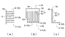
- a front view of the integrated device as viewed from the direction of arrow IX in FIG. (A) is a plan view of the first holding member having a partition portion, (b) is a right side view of the first holding member, and (c) is a front view of the first holding member.
- FIG. 10 is an enlarged cross-sectional view taken along the line XI-XI of FIG.
- A is a plan view of the second holding member having a partition portion
- (b) is a right side view of the second holding member
- (c) is a front view of the second holding member.
- FIG. 12 is an enlarged cross-sectional view taken along the line XIII-XIII of FIG.
- FIG. 14 is an enlarged cross-sectional view taken along the line XV-XV of FIG.
- (A) is a partially omitted side view seen from the direction of arrow XVIII in FIG. 17, and (b) is a partially omitted side view showing a state in which the flat plate work advances while sliding on the upper surface of the partition portion.
- the plan view which shows the state when a flat plate work hits a stopper part.
- a front view showing a state in which a plurality of flat plate works are integrated in the accommodating portion.
- (A) is a front view showing a state in which the space between the holding members including the partition portion is widened and the accumulated material is placed on the receiving portion
- (b) is a plan view thereof.
- (A) is a plan view of the holding member of the third embodiment
- (b) is a front view of the holding member.
- the right side view of the integration apparatus which has the holding member of 4th Embodiment.
- planar view refers to viewing from a vertical direction with respect to the surface of an object such as a flat plate work
- plane view means a vertical direction with respect to the surface of an object such as a flat plate work.
- the "plan view” is a view seen from above to the bottom
- the "side view” is a view seen from one side in the width direction to the other side, and is a “front view”. Is a view seen from the downstream side in the transport direction to the upstream side.
- abbreviation means to include a range permitted in the technical field of the present invention.
- FIG. 1 shows a plan view of a flat plate work.
- the plan view shape of the flat plate work 1 is not particularly limited, and for example, a substantially rectangular shape (a substantially rectangular shape is a substantially rectangular shape or a substantially square shape), a substantially triangular shape, a substantially hexagonal shape, or a substantially polygonal shape or a substantially circular shape. , A substantially elliptical shape, an irregular shape in which these shapes are combined, and the like.
- the "abbreviation" of the substantially rectangular shape, the substantially triangular shape, and the substantially polygonal shape is, for example, a shape in which the corners are chamfered, a shape in which a part of the side is slightly bulged or recessed, or a shape in which the side is slightly curved. Shape etc. are included.
- the "abbreviation" of the substantially circular shape and the substantially elliptical shape includes, for example, a shape in which a part of the circumference is slightly bulged or recessed, a shape in which a part of the circumference is slightly straight or diagonal, and the like.
- FIG. 1 illustrates a flat plate work having a substantially rectangular shape in a plan view.
- the substantially rectangular shape is a plan view shape having a long side (side along the long axis) and a short side (side along the short axis).
- FIG. 1 shows a substantially rectangular flat plate work in which four rectangular corners are chamfered, the corners may be right angles.
- the flat plate work is obtained from any web.
- the type of the flat plate work (and the web on which the flat plate work is based) is not particularly limited, and any synthetic resin film, any plastic plate, any metal thin plate, and two or more kinds of arbitrary layers are laminated. Laminated plates and the like can be mentioned.
- a flat plate work (and a web containing an optical film) including an optical film is used.
- the flat plate work including the optical film may be composed of only the optical film, or may have components other than the optical film and the optical film.
- FIG. 2 is a configuration example of a flat plate work including an optical film
- FIG. 3 is another configuration example of a flat plate work including an optical film.
- the flat plate work 1 includes an optical film 11, a separator film 13, and an adhesive layer 12 that is interposed between the optical film 11 and the separator film 13 to bond both films 11 and 13. Have.
- the pressure-sensitive adhesive layer 12 is firmly adhered to the optical film 11 and is detachably adhered to the separator film 13.
- the separator film 13 can be peeled off at the interface with the pressure-sensitive adhesive layer 12. When the flat plate work 1 is used, the separator film 13 is usually peeled off and removed.
- the flat plate work 1 may not have the pressure-sensitive adhesive layer 12 and the separator film 13.
- the optical film 11 includes an optical functional film.
- the optical functional film include a splitter, a retardation film, a light diffusing film, a brightness improving film, an antiglare film, and a light reflecting film.
- the splitter is a film having a property of transmitting light (polarized light) vibrating in a specific direction and blocking light vibrating in the other direction.
- the retardation film is a film exhibiting optical anisotropy, and examples thereof include stretched films such as acrylic resins, cycloolefin resins, and cellulosic resins.
- the optical film 11 may include a protective film.
- the protective film is laminated for the purpose of protecting the optical functional film. As the protective film, a colorless and transparent film is typically used.
- the optical film 11 of the flat plate work 1 illustrated in FIG. 2 has a first protective film 111, a polarizing element 112, and a second protective film 113 in this order from the bottom of the drawing.
- One laminated film is formed by adhering the films 111 to 113 to each other.
- the other flat plate work 1 has a retardation film 115 as the optical film 11. Further, the surface protective film 16 is laminated on the surface of the optical film 11 (the surface of the retardation film 115) via the pressure-sensitive adhesive layer 17. The surface protective film 16 can be peeled off from the surface of the optical film 11 (phase difference film 115), for example, with the pressure-sensitive adhesive layer 17.
- the pressure-sensitive adhesive layer 12 and the separator film 13 are provided on the back surface of the optical film 11, but the pressure-sensitive adhesive layer 12 and the separator film 13 may not be provided.
- the flat plate work 1 including the optical film 11 is not limited to the layer structure of FIGS. 2 and 3, and can be variously changed.
- the flat plate work 1 may include two or more layers of optical functional films, or may be composed of only one layer of optical functional films.
- FIGS. 4 and 5 show a system including the integration device of the present invention.
- the system of this illustrated example can be carried out at least until the flat plate work obtained from the web is collected, collected, and sent to the next process.
- the system includes a work manufacturing zone Z1 for manufacturing a flat plate work, a work transport zone Z2 for transporting the flat plate work 1 obtained in the work manufacturing zone Z1 to the work integration zone Z3, and a flat plate.
- Arbitrary processing is applied to the work accumulation zone Z3 for accumulating and collecting the work 1, the accumulator transport zone Z4 for transporting the aggregate 100 of the flat plate work 1 integrated in the work integration zone Z3 to the next process, and the aggregate 100. It has a next step zone Z5 to be performed.
- the work manufacturing zone Z1 is provided with a work forming device D1 for forming a flat plate work 1 including a conveyor 26 for transporting the flat plate work 1 to the downstream side.
- this conveyor 26 is referred to as an "upstream conveyor 26".
- the upstream conveyor 26 has, for example, an endless belt and is rotated by rollers.
- the upstream conveyor 26 transfers the formed flat plate work 1 to a conveyor described later.
- the work forming apparatus D1 forms the flat plate work 1 from the web 180.
- the work forming device D1 is, for example, a cutting device.
- the cutting device (work forming device D1) includes a cutting blade 21 for cutting the flat plate work 1 from the web 180, a blade receiving sheet 22 for receiving the cutting edge of the cutting blade 21, and a pedestal 23 arranged on the back surface of the blade receiving sheet 22. And have.
- the blade receiving sheet 22 has an endless shape and is rotated by a roller. By pressing the cutting blade 21 against the long strip-shaped web 180 sent from the upstream side and cutting the web 180, a plurality of flat plate works 1 can be continuously formed. Normally, at least both sides of the web 180 in the width direction are collected as a cutting residue 182 (so-called slag).
- the feeding direction of the web 180 and the collecting direction of the cutting residue 182 are indicated by arrows.
- the web 180 (and the flat plate work 1 formed) is, for example, a film containing an optical film, as described above.
- a cutting pattern in which the cutting residual portion 182 occurs only on both side portions is illustrated.
- a plurality of flat plate works 1 having a gap between adjacent flat plate works 1 substantially equal to the blade thickness of the cutting blade 21 can be obtained.
- the web 180 may be cut by a cutting pattern in which a cutting residue is generated between the adjacent flat plate works 1.
- a plurality of flat plate works 1 in which the gap between the adjacent flat plate works 1 is sufficiently larger than the blade thickness can be obtained.
- the work transfer zone Z2 is provided with a conveyor 3 for transporting the flat plate work 1 from the upstream side to the downstream side.
- the conveyor 3 sequentially conveys a plurality of flat plate works 1 from the upstream side to the downstream side.
- the transport direction is a direction orthogonal to the width direction in a plan view.
- the downstream side is the opposite side to the upstream side.
- the downstream side is the side on which the flat plate work 1 is transported.
- the flat plate work 1 is conveyed downstream by the conveyor 3 in a state where a plurality of columns in the width direction and a plurality of rows in the transfer direction are lined up.
- the number of rows of the flat plate work 1 is not particularly limited, and is 2 or more, preferably 3 or more.
- FIG. 5 illustrates a case where the flat plate works 1 are formed in five rows from the web 180 for convenience, and the flat plate works 1 are conveyed side by side in five rows in the width direction.
- the number of columns refers to the number of flat plate works 1 arranged in the width direction.
- FIG. 5 illustrates a case where the flat plate work 1 having a substantially rectangular shape (substantially rectangular shape) in a plan view is formed by the work forming apparatus D1.
- the flat plate work 1 to be formed is not limited to a substantially rectangular shape (substantially rectangular shape).
- FIG. 5 illustrates a case where the flat plate work 1 having a substantially rectangular shape in a plan view is transported in a state where one side (for example, a side along the long axis) is substantially parallel to the transport direction.
- the present invention is not limited to this, and the flat plate work 1 may be conveyed in a state where one side (for example, a side along the long axis) is inclined with respect to the conveying direction.
- the inclination with respect to the transport direction means that it is not substantially parallel or substantially right angle.
- the above-mentioned substantially parallel means not only strict parallelism but also includes an error range.
- substantially parallel is within a range of strict parallel ⁇ 5 degrees, preferably within a range of strict parallel ⁇ 3 degrees.
- the above-mentioned substantially right angle means not only a strict right angle but also an error range.
- a substantially right angle is within a strict right angle of ⁇ 5 degrees, preferably within a strict right angle of ⁇ 3 degrees.
- the conveyor 3 has a transport surface 3a on which the flat plate work 1 is placed and transported.
- the conveyor 3 has, for example, an endless belt and is rotated by rollers.
- the upper surface of the belt constitutes the transport surface 3a.
- a belt-shaped belt is used as the belt.
- a linear belt 32 may be used as shown in FIG.
- a plurality of linear belts 32 are provided at predetermined intervals in the transport direction (intervals so that the flat plate work 1 does not fall).
- the transport surface 3a of the conveyor 3 is formed by connecting the upper surfaces of the plurality of linear belts 32.
- the peripheral speed of the conveyor 3 is set to be the same as or faster than the peripheral speed of the upstream conveyor 26.
- the peripheral speed of the conveyor 3 is faster than the peripheral speed of the upstream conveyor 26. Therefore, the flat plate work 1 transferred from the upstream conveyor 26 to the conveyor 3 is quickly sent to the downstream side. Therefore, although the line spacing of the flat plate work 1 being conveyed by the upstream conveyor 26 is dense, the line spacing of the flat plate work 1 being conveyed by the conveyor 3 is relatively large. The faster the peripheral speed of the conveyor 3, the larger the line spacing of the flat plate work 1 conveyed by the conveyor 3.
- the work integration zone Z3 is provided with an integration device D3 for the flat plate work 1.
- the integration device D3 is arranged outside the downstream edge 3b of the conveyor 3.
- the accumulator D3 has a holding member 4 that holds the accumulator 100.
- the aggregate 100 is a stack of a plurality of flat plate works 1 in the thickness direction. Details of the integration device D3 will be described later.
- the accumulated material transport zone Z4 is provided with a transport device D4 for moving the holding member 4 of the integrated device D3.
- the transport device D4 connects at least the work integration zone Z3 and the next process zone Z5, and is, for example, endless (annular) in a plan view shown in FIG.
- the transport device D4 includes a passage portion 9 arranged in a plan view ring including a work integration zone Z3 and a next process zone Z5, and a plurality of moving bodies (not shown) movably provided in the passage portion 9.
- the holding member 4 on which the aggregate 100 (plural flat plate works 1) is placed moves to the next process zone Z5 through the transfer device D4, and the aggregate 100 is taken out in the next process zone Z5.
- the empty holding member 4 moves again to the work integration zone Z3 through the transport device D4, and the flat plate work 1 is integrated again in the holding member 4.
- a series of operations of accumulating and collecting the flat plate work 1 continuously manufactured from the web 180 and transporting it to the next process is performed.
- 5 and 6 show the movement of the holding member 4 with arrows.
- 5 and 6 show a state in which the holding members 4 as a set of five are distributed and arranged at three locations on the transport device D4, but the number of the holding members 4 is limited to this. It's not a thing. In practice, a large number of holding members 4 are attached to the transport device D4. Needless to say, the operation of each device in the present invention and the members and parts constituting the device are controlled by a control unit (not shown) including a computer.
- the next process zone Z5 is a zone in which the aggregate 100 or each flat plate work 1 constituting the aggregate 100 is subjected to arbitrary processing. Examples of the next step include inspection of the flat plate work 1 and boxing of the aggregate 100.
- Reference numeral D5 indicates a workbench or the like for the next process.
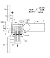
- FIG. 7 is a plan view of the integration device D3
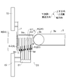
- FIG. 8 is a right side view seen from the arrow VIII direction of FIG. 7
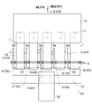
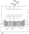
- FIG. 9 is a front view seen from the arrow IX direction of FIG. 7.
- the upstream side of the conveyor 3 is omitted.
- the drive devices 72 and 82 of the stopper portion 7 and the temporary bottom portion 8 are not shown, and in FIG. 9, the conveyor 3 and the transfer device D4 are not shown.
- a holding member 4 having a partition portion 5 is arranged on the outside of the downstream edge 3b of the conveyor 3.
- the holding member 4 has a partition portion 5 and a receiving portion 6 provided below the partition portion 5.
- the receiving portion 6 is a portion on which the aggregate 100 is placed.
- the receiving portion 6 extends to one side (one side in the width direction) of the partition portion 5.
- the holding member 4 having the receiving portion 6 has a substantially L-shape when viewed from the front.
- the partition portion 5 (holding member 4) is provided at least corresponding to each row of the flat plate work 1 conveyed by the conveyor 3.
- the adjacent partition 5 defines an accommodating portion 42 for accumulating the flat plate work 1, and preferably, the adjoining partition 5 and the receiving portion 6 between the partition 5 define the accommodating portion 42. is doing.
- the accommodating portion 42 is a space for accommodating the aggregate 100.
- the minimum number of partition portions 5 (holding members 4) arranged outside the downstream edge 3b of the conveyor 3 is the number of rows of the flat plate work 1.
- the holding members 4) having the partition portion 5 are arranged at intervals in the width direction.
- FIG. 7 to 9 illustrate a case where four rows of flat plate works 1 are conveyed by the conveyor 3, and therefore, five partition portions 5 (holding members 4) are arranged on the downstream edge 3b of the conveyor 3. Has been done.
- the number of rows of the flat plate work 1 is not limited.
- the number of partition portions 5 (holding members 4) arranged outside the downstream edge 3b of the conveyor 3 is appropriately set according to the number of rows of the flat plate work 1.
- the plurality of holding members 4 arranged in the width direction are independently fixed to the moving body (not shown) of the transport device D4 via the connecting portion 91.
- a moving body (not shown) is provided in the passage portion 9 of the transport device D4.
- the moving body can be stopped at an arbitrary position of the passage portion 9 and can move along the passage portion 9 at an arbitrary speed. Therefore, the plurality of holding members 4 are independently attached to the passage portion 9 via the moving body in a movable state.
- the passage portion 9 is fixed to the installation location (frame of the device, etc.).
- the plurality of holding members 4 having the partition portion 5 can be independently displaced in the width direction by the moving body.
- the displacement means positioning at an arbitrary position and stopping, and arbitrarily changing the stopped position.
- each of the partition portions 5 (holding member 4) can independently stop at a predetermined position and move along the passage portion 9 at a predetermined speed. Therefore, the interval (interval in the width direction) of the adjacent partition portions 5 (holding member 4) can be arbitrarily changed, and the interval is appropriately set when the flat plate work 1 is integrated or when the integrated object 100 is conveyed. Will be done.
- the number of partition portions 5 (holding members 4) attached to the transport device D4 is not limited to the number of rows of the flat plate work 1 + 1, and in practice, the number of partition portions 5 (holding members 4) greatly exceeds that. They are independently attached to the transport device D4.
- Each partition 5 has an upper surface 5a that temporarily supports the flat plate work 1 that comes out of the downstream edge 3b by being conveyed by the conveyor 3.
- the upper surface 5a of the partition 5 is flat.
- the upper surface 5a of the partition portion 5 may be inclined with respect to the horizontal, but is preferably horizontal.
- each partition portion 5 is arranged so that the upper surface 5a of each partition portion 5 is in the same plane as the transport surface 3a of the conveyor 3 or is located slightly below the transport surface 3a. In the illustrated example, the upper surface 5a of each partition 5 is located slightly below the transport surface 3a of the conveyor 3 (see FIG. 8). Since the upper surface 5a is positioned below, the flat plate work 1 smoothly moves from the conveyor 3 to the upper surface 5a of the partition portion 5, and easily falls to the accommodating portion 42 due to gravity.
- the partition portion 5 has an upper portion 51 having an upper surface 5a extending in the transport direction and a side wall portion extending in the vertical direction in the side view shown in FIG.
- the upper surface 5a of the partition portion 5 may be subjected to a slip treatment, if necessary.
- the slip treatment include a method of applying a slip agent such as silicone to the upper surface 5a of the partition portion 5, or a method of attaching a slip tape (tape having a surface) to the partition portion 5.
- the sliding tape 56 is attached to the partition portion 5, and in this case, the upper surface of the tape 56 constitutes the upper surface 5a of the partition portion 5.
- the side wall portion may be plate-shaped.
- the side wall portion is composed of a plurality of rod-shaped portions 52 in order to project the temporary bottom portion 8 to be described later above the receiving portion 6.
- the upper part of the plurality of rod-shaped portions 52 is connected to the upper portion 51, and the receiving portion 6 is connected to the lower part of the plurality of rod-shaped portions 52, respectively.
- the plurality of rod-shaped portions 52 are connected to the upper portion 51 with a gap 52c, respectively.
- the plurality of rod-shaped portions 52 form a wall because the plurality of rod-shaped portions 52 are continuous while having a gap 52c.
- the plurality of holding members 4 may be the same or different.
- two types of holding members 4 having different receiving portions 6 are alternately arranged in the width direction.
- first holding member 4-1 first holding member 4-1
- second holding member 4-2 second holding member 4-2
- first holding member 4-1 first holding member 4-1
- first holding member 4-1 second holding member 4-1
- first holding member 4-1 first holding member 4-1
- second holding member 4-2 second holding member 4-2
- first holding member 4-1 has a partition portion 5 and a receiving portion 6 provided below the partition portion 5.
- the receiving portion 6 of the first holding member 4-1 is referred to as "first receiving portion 6-1".
- the partition portion 5 has an upper portion 51 having a slipped upper surface 5a and a side wall portion (plurality of rod-shaped portions 52) composed of a plurality of rod-shaped portions 52.
- a plurality of first receiving portions 6-1 are provided, and each is composed of a rod-shaped member. Since the plurality of first receiving portions 6-1 are continuously arranged with a gap, the plurality of first receiving portions 6-1 form a pedestal. As shown in FIG. 10B, the plurality of first receiving portions 6-1 are arranged at the same height position (horizontal) as each other. The height positions of the plurality of first receiving portions 6-1 are not limited to the same height as each other, and the first receiving portion 6-1 on the left side of the paper surface shown in FIG. 10B is the first receiving portion on the right side of the paper surface. It may be lower than 6-1.
- Each of the plurality of first receiving portions 6-1 is provided so as to extend from below the plurality of rod-shaped portions 52 to one side in the width direction.
- the base of the first receiving portion 6-1 is connected below the rod-shaped portion 52, and the tip end portion (the end portion on the opposite side of the base portion) of the first receiving portion 6-1 is a free end.
- the outer diameter of the first receiving portion 6-1 decreases toward the tip portion thereof so that the first receiving portion 6-1 can be reliably inserted into the insertion hole 66 of the second receiving portion 6-2, which will be described later.
- the length (length in the extending direction) of the first receiving portion 6-1 is not particularly limited, and may be sufficient as long as the aggregate 100 is placed and it does not fall naturally.
- the first receiving portion 6-1 may be extended so as to extend at a right angle to the partition portion 5 (the side wall portion formed of the rod-shaped portion 52).
- the upper surface of the first receiving portion 6-1 is provided on the partition portion 5 (rod-shaped portion 52).
- it may be extended at an acute angle. That is, the first receiving portion 6-1 is attached to the partition portion 5 so that the angle ⁇ formed by the upper surface of the first receiving portion 6-1 and the side surface of the partition portion 5 (the side wall portion composed of the rod-shaped portion 52) is an acute angle. On the other hand, it may be inclined.
- the tip portion of the first receiving portion 6-1 is located above the base portion of the first receiving portion 6-1.
- the angle ⁇ is not particularly limited, but if it is too close to 90 degrees, it does not substantially change to a right angle, and if it is too large, a large number of flat plate works 1 may not be integrated. From this point of view, the angle ⁇ is, for example, more than 0 degrees and 20 degrees or less, and further more than 0 degrees and 5 degrees or less.
- the second holding member 4-2 has a partition portion 5 and a receiving portion 6 provided below the partition portion 5, similarly to the first holding member 4-1.
- the receiving portion 6 of the second holding member 4-2 is referred to as "second receiving portion 6-2".
- the partition portion 5 has an upper portion 51 and a side wall portion (a plurality of rod-shaped portions 52).
- the partition portion 5 of the second holding member 4-2 has the same configuration as the partition portion 5 of the first holding member 4-1.
- a plurality of second receiving portions 6-2 are provided, and each of them is composed of a rod-shaped member. Since the plurality of second receiving portions 6-2 are continuously arranged with a gap, the plurality of second receiving portions 6-2 form a pedestal. As shown in FIG.
- the plurality of second receiving portions 6-2 are arranged at the same height position (horizontal) as each other.
- the height positions of the plurality of second receiving portions 6-2 are not limited to the same height as each other, and the second receiving portion 6-2 on the left side of the paper surface shown in FIG. 12B is the second receiving portion on the right side of the paper surface. It may be lower than 6-2.
- Each of the plurality of second receiving portions 6-2 is provided so as to extend from below the plurality of rod-shaped portions 52 to one side in the width direction.
- the second receiving portion 6-2 has an insertion space 64 into which the first receiving portion 6-1 is inserted in the extending direction thereof.
- the second receiving portion 6-2 is composed of an elongated rod having a U-shape continuous in the extending direction thereof (the second receiving portion 6-2 is formed like a pipe from which the upper surface is removed).
- the base of the second receiving portion 6-2 is connected below the rod-shaped portion 52, and the tip end portion (the end portion opposite to the base portion) of the second receiving portion 6-2 is a free end.
- an insertion hole 66 is opened below the rod-shaped portion 52 so that the first receiving portion 6-1 can be inserted.
- the length (length in the extending direction) of the second receiving portion 6-2 is not particularly limited, and may be sufficient as long as the aggregate 100 is placed and it does not fall naturally.
- the second receiving portion 6-2 may be extended so as to extend at a right angle to the partition portion 5 (rod-shaped portion 52).
- the upper surface of the second receiving portion 6-2 is the same as that of the first receiving portion 6-1 so that the aggregate 100 is not inadvertently dropped when the aggregate 100 is transported to the next process zone Z5.
- the partition portion 5 (rod-shaped portion 52) may be extended at an acute angle.
- the angle ⁇ of the second receiving portion 6-2 is, for example, more than 0 degrees and 20 degrees or less, and further more than 0 degrees and 5 degrees or less, as in the case of the first receiving portion 6-1.
- the first holding member 4-1 and the second holding member 4-2 are arranged alternately in the width direction.
- the first holding member 4-1 and the second holding member 4-2 that are adjacent to each other can overlap the first receiving portion 6-1 and the second receiving portion 6-2.
- each holding member 4 is moved so that the distance between the adjacent holding members 4 becomes small.
- the first receiving portion 6-1 passes through the insertion hole 66 of the second holding member 4-2 and enters the insertion space 64 of the second receiving portion 6-2.
- the receiving portions 6 of the adjacent holding members 4 may have the same configuration.
- the receiving portions 6 have the same configuration and the adjacent holding members 4 are brought close to each other, the tip end portion of the receiving portion 6 of one holding member 4 interferes with the base portion of the receiving portion 6 of the other partition portion 5. Therefore, when the receiving portions 6 have the same configuration, the minimum value of the spacing between the holding members 4 (partition portions 5) is the length of the receiving portions 6.
- the first holding member 4-1 and the second holding member 4-2 are alternately arranged in the width direction, the first receiving portion 6-1 inserts the second receiving portion 6-2 as described above. It enters the space 64, and the first receiving portion 6-1 and the second receiving portion 6-2 overlap each other without interfering with each other.
- the material for forming the holding member 4 is not particularly limited.
- the holding member 4 is formed of a material having excellent strength, such as a metal or a hard resin.
- the integrating device D3 has a stopper portion 7.
- the stopper portion 7 is arranged on the downstream side of the partition portion 5.
- the stopper portion 7 is provided to prevent the flat plate work 1 from advancing while sliding on the upper surface 5a of the partition portion 5.
- the stopper portions 7 are provided at least between the adjacent partition portions 5.
- the same number of stopper portions 7 as the number of holding members 4 arranged outside the downstream edge 3b of the conveyor 3 are provided.
- the stopper portion 7 is arranged so as not to come into contact with the partition portion 5.
- the stopper portions 7 are arranged in the middle of the adjacent partition portions. As shown in FIG.
- the stopper portion 7 may be provided so as to intersect at least the upper surface 5a of the partition portion 5 with respect to the same plane.
- the stopper portion 7 is composed of a plate-shaped body.
- the stopper portion 7 made of a plate-shaped body includes a portion that intersects the upper surface 5a of the partition portion 5 with respect to the same plane, and extends vertically from the portion.
- the stopper portion 7 preferably extends to the vicinity of the receiving portion 6 in order to prevent the flat plate work 1 accumulated in the accommodating portion 42 from falling off from the downstream side.
- the stopper portion 7 extends to the extent that the lower end portion 7d of the stopper portion 7 is located slightly above the receiving portion 6.
- the length of the stopper portion 7 in the width direction is not particularly limited, and it is preferable that the stopper portion 7 does not come into contact with the partition portion 5.
- the material for forming the stopper portion 7 is not particularly limited.
- the stopper portion 7 is formed of a material having excellent strength, such as metal or hard resin.
- Each stopper portion 7 can be moved in the vertical direction.
- each stopper portion 7 is attached to the drive device 72 via the connecting portion 71.
- the drive device 72 is fixed to the installation location (frame of the device, etc.).
- each stopper portion 7 is arranged so as to intersect the same plane as the upper surface 5a of the partition portion 5.
- each stopper portion 7 is moved upward by the drive device 72 so that the holding member 4 does not interfere with the stopper portion 7.
- each stopper portion 7 is retracted above the upper surface 5a of the partition portion 5 so as not to intersect the upper surface 5a of the partition portion 5.
- the drive device may be set so that each stopper portion 7 can be moved in the transport direction.
- the moving direction of the stopper portion 7 is indicated by a thick arrow in FIG.
- the flat plate work 1 traveling on the upper surface 5a of the partition portion 5 may not hit the stopper portion 7.
- the position of the stopper portion 7 can be moved closer to the downstream side edge 3b of the conveyor 3 or far from the downstream side edge 3b.
- the drive device may be set so that each stopper portion 7 can be moved in the width direction. Since the stopper portion 7 can be displaced in the width direction, the position of each stopper portion 7 in the width direction can be appropriately adjusted according to the distance between the adjacent partition portions 5.
- the integration device D3 has a temporary bottom portion 8 that can move up and down.
- the temporary bottom portion 8 functions as a cradle that temporarily supports the flat plate work 1 that falls on the accommodating portion 42.
- the temporary bottom portion 8 is provided so as to be able to enter the accommodating portion 42 and exit from the accommodating portion 42.
- the temporary bottom portion 8 is made of a plate-shaped body (or a rod-shaped body) that can enter the gap 52c of the rod-shaped portion 52 of the holding member 4.
- the temporary bottom portion 8 is composed of a plurality of plate-shaped bodies that enter the gaps 52c of all the rod-shaped portions 52.
- the material for forming the temporary bottom portion 8 is not particularly limited.
- the temporary bottom portion 8 is formed of a material having excellent strength, such as a metal or a hard resin.
- the upper end portion 8a of the temporary bottom portion 8 may be flat, but is preferably arcuate as shown in FIG. 8 from the viewpoint of preventing scratches on the falling flat plate work 1.
- the upper end portion 8a of the temporary bottom portion 8 may be formed of a cushioning material such as rubber, or the upper end portion 8a of the temporary bottom portion 8 may be provided with a cushioning material such as rubber (not shown).
- the plurality of temporary bottom portions 8 may be at the same height position. That is, a plurality of temporary bottom portions 8 may be provided so that the virtual line connecting the upper end portions 8a of each temporary bottom portion 8 is horizontal when viewed from the side. Alternatively, as shown in FIG. 8, it is preferable that the plurality of temporary bottom portions 8 are gradually lowered toward the stopper portion 7 side (downstream side). That is, it is preferable that a plurality of temporary bottom portions 8 are provided so that the virtual line connecting the upper end portions 8a of each temporary bottom portion 8 is inclined in a side view.
- the flat plate work 1 that has fallen to the accommodating portion 42 and is placed on the upper end portion 8a of the temporary bottom portion 8 is a stopper according to the inclination. Move to part 7. Since the moved flat plate work 1 hits the stopper portion 7 and stops, the flat plate work 1 is integrated in a vertically aligned state.
- the degree of inclination is not particularly limited, but if it is too small, it becomes difficult for the flat plate work 1 to move toward the stopper portion 7.
- the inclination angle ⁇ of the upper end portion 8a of the temporary bottom portion 8 is, for example, 5 degrees or more and 20 degrees or less, preferably 7 degrees or more and 15 degrees or less. As shown in FIG. 8, the inclination angle ⁇ refers to an angle formed by a horizontal plane and a virtual line connecting the upper end portions 8a of each temporary bottom portion 8.
- a temporary bottom portion 8 may be provided for each holding member 4 so that the housing portions 42 of the plurality of holding members 4 can enter and exit independently of each other.
- a temporary bottom portion 8 may be provided so that the accommodating portions 42 of the plurality of holding members 4 can enter and exit at the same time.
- the temporary bottom portion 8 can simultaneously enter and exit the accommodating portions 42 of the plurality of holding members 4 arranged outside the downstream edge 3b of the conveyor 3.
- the plate-shaped body constituting the temporary bottom portion 8 is an elongated shape that intersects each holding member 4 and extends in the width direction (see FIG. 9).
- the temporary bottom portion 8 is attached to the drive device 82 via the connecting portion 81 so that the temporary bottom portion 8 can be moved in the vertical direction.
- the drive device 82 is fixed to the installation location (frame of the device, etc.).
- the temporary bottom portion 8 enters the gap 52c of the adjacent rod-shaped portions 52 and protrudes above the receiving portion 6 of the holding member 4 (see FIGS. 8 and 9).
- the method of integrating the flat plate work 1 of the present invention includes a conveyor 3 for transporting a plurality of flat plate works 1 from the upstream side to the downstream side, a plurality of partition portions 5 arranged outside the downstream edge 3b of the conveyor 3, and a plurality of partition portions 5. This is carried out using an integration device D3 having a stopper portion 7 arranged on the downstream side of the partition portion 5.
- the flat plate works 1 are sequentially conveyed on the conveying surface 3a of the conveyor 3 in a state where the flat plate works 1 are arranged in a plurality of columns in the width direction and in a plurality of rows in the conveying direction which is a direction orthogonal to the width direction.
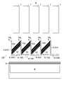
- FIG. 16 is a plan view showing a state in which the flat plate work 1 is conveyed by the upstream conveyor 26 and a state in which the flat plate work 1 is conveyed by the conveyor 3.
- the plurality of flat plate works 1 formed by the work forming apparatus D1 are conveyed to the downstream side by the upstream side conveyor 26 in a state where the rows and columns are closely arranged.
- the conveyor 3 has a higher peripheral speed than the upstream conveyor 26.
- Each flat plate work 1 transferred from the upstream conveyor 26 to the conveyor 3 is conveyed with widening between rows and columns while maintaining a state of being inclined with respect to the conveying direction.
- a plurality of holding members 4 including a partition portion 5 are set at predetermined positions on the outside of the downstream edge 3b of the conveyor 3. As shown in FIG. 17, the partition portion 5 is provided so that the distance W5 between the cores Y and Y of the adjacent partition portions 5 is the same as the distance W1 between the centers of gravity X and X of the flat plate works 1 adjacent to each other between the rows.
- the holding member 4 including the holding member 4 is positioned and set.
- the holding member 4 including the partition portion 5 is positioned and set so that the core Y of each partition portion 5 is displaced to one side in the width direction with respect to the center of gravity X of the flat plate work 1 in each row to be conveyed. ..
- the holding member 4 including the partition portion 5 is positioned and set on the upper surface 5a of each partition portion 5 so that the center of gravity X of the flat plate work 1 in each row to be conveyed does not overlap.
- the plurality of holding members 4 before being arranged outside the downstream edge 3b are compactly collected and moved by the transport device D4. Then, the plurality of holding members 4 together are spread out and positioned on the outside of the downstream edge 3b of the conveyor 3, and are arranged with the above-mentioned spacing.
- the flat plate work 1 conveyed by the conveyor 3 goes out to the outside of the downstream edge 3b and is transferred to the upper surface 5a of the partition portion 5.
- the flat plate work 1 advances while sliding on the upper surface 5a of the partition portion 5.
- the conveyor 3 advances the flat plate work 1 while sliding it on the upper surface 5a of the partition portion 5.
- FIG. 19 when the tip corner portion 1d in the traveling direction of the flat plate work 1 is further pushed out while hitting the stopper portion 7, the flat plate work 1 rotates.
- the flat plate work in the middle of rotation is indicated by a two-dot chain line and is designated by reference numeral 1'.
- the flat plate work 1 that has fallen to the accommodating portion 42 is sequentially accumulated in a state of being inclined with respect to the horizontal. Specifically, by rotating, the flat plate work 1 falls into the accommodating portion 42 with its long axis along the width direction and one short side (side along the short axis) facing down. That is, by rotating itself, the flat plate work 1 falls into the accommodating portion 42 while its long axis is substantially parallel to the width direction in a plan view.
- the short side of the dropped flat plate work 1 contacts the corner defined by the temporary bottom portion 8 and the partition portion 5, and the short side on the opposite side of the flat plate work 1 contacts the partition portion 5 adjacent to the temporary bottom portion 8. .. Therefore, the flat plate work 1 is tilted and accommodated in the accommodating portion 42.
- the edges on both sides of the flat plate work 1 (one short side and the opposite short side) only come into contact with the partition portion 5, so that it is possible to prevent the back surface of the flat plate work 1 from being scratched. ..
- the temporary bottom portion 8 since the temporary bottom portion 8 is provided, the drop distance of the flat plate work 1 can be made as small as possible, and the drop impact on the flat plate work 1 can be made small. That is, in the present invention, the temporary bottom portion 8 may not be provided, but if it is not provided, the flat plate work 1 temporarily falls from the upper surface 5a of the partition portion 5 to the receiving portion 6.
- the distance at which the flat plate work 1 falls at one time can be reduced. Further, since the upper end portions 8a of the plurality of temporary bottom portions 8 are inclined, the flat plate work 1 in contact with the upper end portions 8a of the temporary bottom portion 8 moves to the stopper portion 7 according to the inclination. Therefore, in the accommodating portion 42, the flat plate work 1 is accumulated in a state of being in contact with the stopper portion 7, and an integrated product in which the upper and lower flat plate works 1 are neatly aligned can be obtained.
- each flat plate work 1 sequentially conveyed by the conveyor 3 rotates on the upper surface 5a of the partition portion 5 corresponding to each row, and is accommodated in the accommodating portion 42, respectively. It is necessary to prevent the flat plate work 1 accommodated in each accommodating portion 42 from protruding above the upper surface 5a of the partition portion 5. Therefore, as the number of integrated flat plate works 1 increases, the temporary bottom portion 8 is lowered accordingly.
- the temporary bottom portion 8 is lowered to retract below the receiving portion 6, and the stopper portion 7 is raised to form the partition portion. It is evacuated above the upper surface 5a of 5.
- the temporary bottom portion 8 is lowered, the inclined aggregate 100 is transferred onto the receiving portion 6.
- the holding member 4 can be moved by retracting the temporary bottom portion 8 and the stopper portion 7.
- the holding member 4 may be conveyed to the next step in a state where the aggregate 100 is inclined, but it is unstable if it remains in an inclined state. Therefore, from the state shown in FIG. 21, each holding member 4 is moved in the width direction to widen the distance between the adjacent holding members 4. Then, as shown in FIGS. 22 (a) and 22 (b), the back surface of the aggregate 100 is placed along the receiving portion 6. If the holding member 4 is moved in a state where the back surface of the aggregate 100 is in contact with the receiving portion 6, the aggregate 100 can be stably conveyed to the next step.
- the receiving portion 6 extends at an acute angle with respect to the partition portion 5, as shown in the figure, the aggregate 100 in contact with the receiving portion 6 is entirely with the tip end portion side of the receiving portion 6 as the upper position. Tilt at an acute angle. Therefore, it is possible to prevent the flat plate work 1 from falling off from the tip end side (free end side) of the receiving portion 6 when the aggregate 100 held by the holding member 4 is conveyed.
- the holding member 4 accommodating the aggregate 100 is moved, the waiting empty holding member 4 is arranged outside the downstream edge 3b of the conveyor 3.
- the stopper portion 7 is lowered and the temporary bottom portion 8 is raised, so that the state shown in FIGS. 7 to 9 is set.
- the flat plate work 1 is accumulated in the accommodating portion 42. After the fact, this is repeated, and the flat plate work 1 can be continuously accumulated and collected, and sequentially conveyed to the next process.
- FIG. 23 is a plan view of the integration device D3 that implements the integration method of the second embodiment.
- a plurality of holding members 4 including a partition portion 5 are set at predetermined positions on the outside of the downstream edge 3b of the conveyor 3.
- the distance W5 between the cores Y of the adjacent partition portions 5 is the same as the distance W1 between the centers of gravity X and X of the flat plate works 1 adjacent to each other between the rows.
- the holding member 4 including the partition portion 5 is positioned and set so that the core Y of each partition portion 5 deviates from the center of gravity X of the corresponding flat plate work 1.
- the flat plate work 1 conveyed by the conveyor 3 goes out to the outside of the downstream edge 3b and is transferred to the upper surface 5a of the partition portion 5.
- the flat plate work 1 advances along the extending direction of the upper surface 5a of the partition 5 while sliding on the upper surface 5a of the partition 5.
- the flat plate work 1 does not rotate, and the flat plate work 1 on the upper surface 5a of the partition portion 5 falls to the side where the center of gravity is deviated from the upper surface 5a of the partition portion 5, and the accommodating portion on that side. It falls to 42. Therefore, the flat plate work 1 is accommodated in the accommodating portion 42 in the same direction as during transportation (that is, the flat plate work 1 is accommodated in the accommodating portion 42 with the long axis substantially parallel to the conveying direction). Since the distance between the adjacent partition portions 5 is smaller than the length of the minor axis of the flat plate work 1, the flat plate works 1 that have fallen into the accommodating portion 42 are sequentially accumulated in a state of being inclined with respect to the horizontal. To.
- the flat plate work 1 in each row falls from the upper surface 5a of the partition portion 5 corresponding to each row to the accommodating portion 42 and is sequentially accumulated.
- the stopper portion 7 and the temporary bottom portion 8 are evacuated so that the accumulated material 100 is in contact with the receiving portion 6.
- the holding member 4 is conveyed to the next process.
- the flat plate work 1 is conveyed in a state where the long axis is substantially parallel to the transport direction
- the flat plate work 1 is conveyed in a state where the short axis is substantially parallel to the transport direction. In the same case, it can be carried out in the same way.
- FIG. 26 shows the holding member 4 of the third embodiment.
- the holding member 4 has a partition portion 5 and a right receiving portion 6R and a left receiving portion 6L provided below the partition portion 5.
- the right receiving portion 6R extends to one side in the width direction of the partition portion 5, and the left receiving portion 6L extends to the opposite side.
- the right receiving portion 6R and the left receiving portion 6L are portions on which the aggregate 100 is placed.
- the holding member 4 having the two receiving portions 6 has an inverted T shape when viewed from the front.
- the right receiving portion 6R and the left receiving portion 6L may have a long extending shape, and both receiving portions 6R and 6L may have the same shape.
- the right receiving portion 6R is made of a rod-shaped member as in the first receiving portion 6-1 of the first embodiment.
- the left receiving portion 6L has an insertion space 64 as in the second receiving portion 6-2 of the first embodiment.
- the upper surfaces of the right receiving portion 6R and the left receiving portion 6L may extend at an acute angle with respect to the partition portion 5, or extend at a right angle (horizontal) with respect to the partition portion 5. You may.
- FIG. 27 shows a state when the holding member 4 of the third embodiment is arranged on the outer side of the downstream edge 3b of the conveyor 3 with a gap. However, the conveyor 3 and the like are omitted, and only the holding member 4 is shown.
- the accommodating portion 42 is defined by the adjacent partition portion 5, the right receiving portion 6R, and the left receiving portion 6L. At the time of use, the flat plate work 1 is accumulated in the accommodating portion 42.
- the receiving portions 6 (first receiving portions 6-1 and second receiving portions 6-2) of the holding member 4 of each of the above embodiments are arranged at the same height position (horizontal) as each other, but are arranged in an inclined shape. It may have been done.
- the plurality of receiving portions 6 may be gradually lowered toward the stopper portion 7 side (downstream side) in a side view. That is, a plurality of receiving portions 6 may be provided so that the virtual line connecting the lower end portions 6d of the plurality of receiving portions 6 is inclined in the side view.
- the inclination angle ⁇ of the plurality of receiving portions 6 is, for example, more than 0 degrees and 5 degrees or less, preferably more than 0 degrees and 3 degrees or less. As shown in FIG. 28, the inclination angle ⁇ refers to an angle formed by a horizontal plane and a virtual line connecting the lower end portions 6d of the receiving portion 6.
- each of the above embodiments are inclined, for example, as shown in FIG. 29, the upper end portions 8a of each temporary receiving portion 8 may be at the same height position. In this case, the virtual line connecting the upper end portions 8a of each temporary bottom portion 8 is horizontal in the side view.
- FIG. 30 shows some flat plate works 1 having a plan view shape to which the present invention can be applied.
- the flat plate work 1 other than the shape shown in FIG. 30 can also be integrated by the integration device D3 of the present invention.
- FIG. 1A is a flat plate work 1-1 in which a through hole 1e is formed in a plane.
- FIG. 3B is a flat plate work 1-2 in which the notch 1f is formed.
- FIG. 3C is a flat plate work 1-3 in which a through hole 1e and a notch 1f are formed.
- FIG. 3D is a flat plate work 1-4 having a plan view shape in which two circles are combined.
- FIG. 3E is a flat plate work 1-5 having a plan view shape in which three circles are combined.
- the number of through holes 1e and the number of notches 1f are not limited to the illustrated examples, and can be changed as appropriate. Further, the formation or non-formation of the through hole 1e and the notch 1f can be appropriately changed.
- each flat plate work 1 shown in FIG. 30 has a plan view shape having a long axis and a short axis (both have a long axis in the lateral direction of the paper surface).
Landscapes
- Engineering & Computer Science (AREA)
- Mechanical Engineering (AREA)
- Attitude Control For Articles On Conveyors (AREA)
- Stacking Of Articles And Auxiliary Devices (AREA)
Priority Applications (3)
| Application Number | Priority Date | Filing Date | Title |
|---|---|---|---|
| JP2022551130A JPWO2022064743A1 (https=) | 2020-09-28 | 2021-04-09 | |
| CN202180064504.8A CN116209631A (zh) | 2020-09-28 | 2021-04-09 | 平板工件的堆叠方法以及平板工件的堆叠装置 |
| KR1020237007211A KR20230074714A (ko) | 2020-09-28 | 2021-04-09 | 평판 워크의 집적 방법 및 평판 워크의 집적 장치 |
Applications Claiming Priority (2)
| Application Number | Priority Date | Filing Date | Title |
|---|---|---|---|
| JP2020162051 | 2020-09-28 | ||
| JP2020-162051 | 2020-09-28 |
Publications (1)
| Publication Number | Publication Date |
|---|---|
| WO2022064743A1 true WO2022064743A1 (ja) | 2022-03-31 |
Family
ID=80845138
Family Applications (1)
| Application Number | Title | Priority Date | Filing Date |
|---|---|---|---|
| PCT/JP2021/015041 Ceased WO2022064743A1 (ja) | 2020-09-28 | 2021-04-09 | 平板ワークの集積方法及び平板ワークの集積装置 |
Country Status (5)
| Country | Link |
|---|---|
| JP (1) | JPWO2022064743A1 (https=) |
| KR (1) | KR20230074714A (https=) |
| CN (1) | CN116209631A (https=) |
| TW (1) | TW202231563A (https=) |
| WO (1) | WO2022064743A1 (https=) |
Cited By (1)
| Publication number | Priority date | Publication date | Assignee | Title |
|---|---|---|---|---|
| JP7340653B1 (ja) | 2022-05-16 | 2023-09-07 | 日東電工株式会社 | 枚葉フィルムの製造方法 |
Citations (3)
| Publication number | Priority date | Publication date | Assignee | Title |
|---|---|---|---|---|
| JPS628262U (https=) * | 1985-07-01 | 1987-01-19 | ||
| JP2012111505A (ja) * | 2010-11-22 | 2012-06-14 | Omori Mach Co Ltd | 集積供給システム |
| JP2017077937A (ja) * | 2015-10-19 | 2017-04-27 | 日東電工株式会社 | 平板ワーク搬送台および平板ワーク切断回収システム、ならびに平板ワーク回収方法 |
-
2021
- 2021-04-09 JP JP2022551130A patent/JPWO2022064743A1/ja active Pending
- 2021-04-09 WO PCT/JP2021/015041 patent/WO2022064743A1/ja not_active Ceased
- 2021-04-09 CN CN202180064504.8A patent/CN116209631A/zh active Pending
- 2021-04-09 KR KR1020237007211A patent/KR20230074714A/ko not_active Withdrawn
- 2021-04-19 TW TW110113899A patent/TW202231563A/zh unknown
Patent Citations (3)
| Publication number | Priority date | Publication date | Assignee | Title |
|---|---|---|---|---|
| JPS628262U (https=) * | 1985-07-01 | 1987-01-19 | ||
| JP2012111505A (ja) * | 2010-11-22 | 2012-06-14 | Omori Mach Co Ltd | 集積供給システム |
| JP2017077937A (ja) * | 2015-10-19 | 2017-04-27 | 日東電工株式会社 | 平板ワーク搬送台および平板ワーク切断回収システム、ならびに平板ワーク回収方法 |
Cited By (3)
| Publication number | Priority date | Publication date | Assignee | Title |
|---|---|---|---|---|
| JP7340653B1 (ja) | 2022-05-16 | 2023-09-07 | 日東電工株式会社 | 枚葉フィルムの製造方法 |
| WO2023223756A1 (ja) * | 2022-05-16 | 2023-11-23 | 日東電工株式会社 | 枚葉フィルムの製造方法 |
| JP2023168973A (ja) * | 2022-05-16 | 2023-11-29 | 日東電工株式会社 | 枚葉フィルムの製造方法 |
Also Published As
| Publication number | Publication date |
|---|---|
| KR20230074714A (ko) | 2023-05-31 |
| JPWO2022064743A1 (https=) | 2022-03-31 |
| CN116209631A (zh) | 2023-06-02 |
| TW202231563A (zh) | 2022-08-16 |
Similar Documents
| Publication | Publication Date | Title |
|---|---|---|
| JP5945143B2 (ja) | 光学フィルムロールセットおよび光学フィルムロールセットの製造方法。 | |
| KR101549176B1 (ko) | 광학 필름 라미네이팅 시스템 및 이를 이용한 디스플레이 유닛 제조방법 | |
| KR102733998B1 (ko) | 평판 워크 절단 회수 시스템, 및 평판 워크 절단 회수 방법 | |
| JP6126257B2 (ja) | 光学フィルムロールセットおよび光学フィルムロールセットの製造方法 | |
| EP1588832B1 (en) | Device of forming tire reinforcing layer | |
| WO2022064743A1 (ja) | 平板ワークの集積方法及び平板ワークの集積装置 | |
| TWI630439B (zh) | 光學顯示裝置的生產系統 | |
| KR101779209B1 (ko) | 가스 배리어 필름의 제조 방법 | |
| JP6223439B2 (ja) | 光学表示デバイスの生産システム | |
| TW201348764A (zh) | 光學顯示裝置之生產系統及生產方法 | |
| CN106415375B (zh) | 显示部件制造方法及光学膜层压系统 | |
| KR101420308B1 (ko) | 액정표시패널의 제조방법 및 그 제조방법이 구현된 시스템 | |
| JP6247864B2 (ja) | 搬送台車及び切削加工ユニット | |
| CN105990191A (zh) | 基板输送托台、划线装置以及输送基板的方法 | |
| CN105453160B (zh) | 光学显示设备的生产系统 | |
| KR20060105505A (ko) | 기판 이재 장치, 기판 이재 방법 및 전기 광학 장치의 제조방법 | |
| JP2006308912A (ja) | 光学シートの供給方法及び装置 | |
| TW201925115A (zh) | 基板搬出裝置 | |
| KR102680760B1 (ko) | 광학필름 라미네이팅 시스템 | |
| KR102676762B1 (ko) | 홀 절삭 공구, 이를 포함하는 광학 필름의 홀 형성 장치 및 이를 사용한 광학 필름의 홀 형성 방법 | |
| TW201926522A (zh) | 基板搬出裝置 | |
| CN107656389B (zh) | 液晶显示装置的制造方法 | |
| KR20230160173A (ko) | 평판상 워크의 이송 방법 | |
| KR20160050279A (ko) | 흡착 매트 및 이를 이용한 회전 커터 장치 | |
| KR20200005926A (ko) | 광학 표시소자 제조 시스템 및 방법 |
Legal Events
| Date | Code | Title | Description |
|---|---|---|---|
| 121 | Ep: the epo has been informed by wipo that ep was designated in this application |
Ref document number: 21871879 Country of ref document: EP Kind code of ref document: A1 |
|
| ENP | Entry into the national phase |
Ref document number: 2022551130 Country of ref document: JP Kind code of ref document: A |
|
| NENP | Non-entry into the national phase |
Ref country code: DE |
|
| 122 | Ep: pct application non-entry in european phase |
Ref document number: 21871879 Country of ref document: EP Kind code of ref document: A1 |