WO2022064593A1 - 衝撃吸収フィルム、脆性材料部材を備える製品を製造する方法、及び電子機器 - Google Patents
衝撃吸収フィルム、脆性材料部材を備える製品を製造する方法、及び電子機器 Download PDFInfo
- Publication number
- WO2022064593A1 WO2022064593A1 PCT/JP2020/036018 JP2020036018W WO2022064593A1 WO 2022064593 A1 WO2022064593 A1 WO 2022064593A1 JP 2020036018 W JP2020036018 W JP 2020036018W WO 2022064593 A1 WO2022064593 A1 WO 2022064593A1
- Authority
- WO
- WIPO (PCT)
- Prior art keywords
- absorbing film
- shock absorbing
- display panel
- electronic device
- meth
- Prior art date
- Legal status (The legal status is an assumption and is not a legal conclusion. Google has not performed a legal analysis and makes no representation as to the accuracy of the status listed.)
- Ceased
Links
Images


Classifications
-
- C—CHEMISTRY; METALLURGY
- C08—ORGANIC MACROMOLECULAR COMPOUNDS; THEIR PREPARATION OR CHEMICAL WORKING-UP; COMPOSITIONS BASED THEREON
- C08J—WORKING-UP; GENERAL PROCESSES OF COMPOUNDING; AFTER-TREATMENT NOT COVERED BY SUBCLASSES C08B, C08C, C08F, C08G or C08H
- C08J5/00—Manufacture of articles or shaped materials containing macromolecular substances
- C08J5/18—Manufacture of films or sheets
Definitions
- the present invention relates to a method for manufacturing a product including a shock absorbing film, a brittle material member, and an electronic device.
- one aspect of the present invention is to provide a shock absorbing film which is excellent in shock absorbing property and can be easily bonded to other members even under normal temperature and low pressure conditions.
- One aspect of the present invention provides a shock absorbing film containing an acrylic polymer.
- the shock absorbing film exhibits a glass transition temperature of 0 to 35 ° C. and a storage modulus of 0.1 to 10 GPa at a frequency of 1 ⁇ 10 4 Hz.
- Another aspect of the present invention provides a method of manufacturing a product comprising a brittle material member, comprising attaching the shock absorbing film to the brittle material member at 20-30 ° C.
- an electronic device comprising a housing forming an opening, a cover window closing the opening, and a display panel housed in the housing so as to face the cover window. ..
- the housing has a back cover portion that faces the display panel on the opposite side of the cover window.
- the electronic device further includes the shock absorbing film provided between the cover window and the display panel, or between the back cover portion and the display panel.
- a shock absorbing film which is excellent in shock absorption and can be easily attached to another member even under normal temperature, low pressure or normal pressure conditions.
- an electronic device provided with a display panel and having excellent impact resistance.
- (meth) acryloyl means acryloyl or methacryloyl. This is also true for other similar terms.
- FIG. 1 is a cross-sectional view showing an embodiment of a laminated film including a shock absorbing film.
- the laminated film 15 shown in FIG. 1 has two separators 11 and 12 and a shock absorbing film 1 sandwiched between the separators 11.12.
- the separators 11 and 12 may be, for example, resin films, and examples thereof include polyethylene terephthalate (PET), triacetyl cellulose (TAC), polyethylene naphthalate (PEN), polymethyl methacrylate (PMMA), and polycarbonate (PC). ), Polyethylene (PI), Polyethylene (PE), Polypropylene (PP), Polyvinyl Alcohol (PVA), Polyvinyl Chloride (PVC), Cycloolefin Polymer (COC), Cycloolefin Polymer (COP), Norbornen Resin, Polyether Examples include films containing sulfones, cellophane, aromatic polyamides, or combinations thereof.
- the separators 11 and 12 may have a mold-released surface, and the shock-absorbing film 1 may be provided on the mold-released surface.
- the shock absorbing film 1 is a single-layer film containing an acrylic polymer as a main component.
- the shock absorbing film 1 exhibits a glass transition temperature of 0 to 35 ° C. and a storage elastic modulus of 0.1 to 10 GPa at a frequency of 1 ⁇ 10 4 Hz.
- the glass transition temperature (Tg) and the storage elastic modulus are values determined by the dynamic viscoelasticity measurement of the impact absorbing film 1.
- the dynamic viscoelasticity of the shock absorbing film 1 was measured at ⁇ 40 ° C. in a tensile mode (frequency 1 Hz, strain amount 0.05%) and a heating rate of 5 ° C./min.
- the glass transition temperature can be obtained from the viscoelastic curve (curve showing the relationship between the viscoelastic property and the temperature) obtained by measuring under the condition of raising the temperature from 1 to 80 ° C.
- the glass transition temperature is the temperature at which tan ⁇ has the largest maximum value in the viscoelastic curve showing the relationship between tan ⁇ and temperature.
- the storage elastic modulus at a frequency of 1 ⁇ 10 4 Hz is a value obtained from a master curve having a reference temperature of 25 ° C. obtained by the WLF method.
- the dynamic viscoelasticity of the shock absorbing film 1 is measured while changing the frequency from 0.5 Hz to 50.0 Hz in the tensile mode (strain amount 0.05%). This is repeated for each temperature while raising the temperature from -50 ° C to 40 ° C by 1 ° C, and a master curve with a reference temperature of 25 ° C is obtained from the measurement results by the WLF formula, and 1 ⁇ 10 4 from the master curve.
- the storage elastic modulus at the frequency of Hz is obtained.
- the shock absorbing film 1 When the glass transition degree of the shock absorbing film 1 is 0 to 35 ° C., the shock absorbing film can have excellent bonding properties at room temperature and low pressure. As electronic devices become thinner, the members that make up the electronic devices tend to become thinner, so the importance of being able to easily bond them at room temperature and low pressure is increasing from the viewpoint of improving productivity. From the same viewpoint, the glass transition temperature of the shock absorbing film 1 may be 1 ° C. or higher, 2 ° C. or higher, 3 ° C. or higher, 4 ° C. or higher, 5 ° C. or higher, 6 ° C. or higher, or 7 ° C. or higher, 34. It may be °C or less, 33 °C or less, 32 °C or less, or 31 °C or less.
- the storage elastic modulus of the shock absorbing film 1 at 0 ° C. is 0.1 to 10 GPa
- the shock resistance of the electronic device into which the shock absorbing film 1 is introduced tends to be remarkably improved. Therefore, for example, in an electronic device provided with an ultra-thin glass base material, damage to the glass base material can be effectively suppressed by introducing the shock absorbing film 1.
- the storage elastic modulus of the shock absorbing film 1 at 0 ° C. is 0.2 GPa or more, 0.3 GPa or more, 0.4 GPa or more, 0.5 GPa or more, 0.6 GPa or more, from the viewpoint of adhesiveness at room temperature and low pressure.
- It may be 0.7 GPa or more, 0.8 GPa or more, 0.9 GPa or more, or 1.0 GPa or more, 9.0 GPa or less, 8.0 GPa or less, 7.0 GPa or less, 6.0 GPa or less, 5.0 GPa or less. It may be 4.0 GPa or less, or 3.0 GPa or less.
- the glass transition temperature of the shock absorbing film 1 can be adjusted to 0 to 35 ° C. mainly based on the glass transition temperature of the acrylic polymer.
- the glass transition temperature of the acrylic polymer is controlled by setting the type of monomer and the copolymerization ratio based on the glass transition temperature theoretically calculated based on the glass transition temperature of the homopolymer of the monomer. Is possible. Those skilled in the art will be able to utilize many monomers with known homopolymer glass transition temperatures. Introducing a small molecule compound into the shock absorbing film 1 also tends to lower the glass transition temperature of the shock absorbing film 1.
- Monomers that provide homopolymers with high glass transition temperatures tend to increase the storage elastic modulus of the impact absorbing film 1 at 0 ° C.
- a monomer having an aromatic ring or an aliphatic ring can also appropriately increase the storage elastic modulus of the impact absorbing film 1 at 0 ° C.
- a glass transition temperature of 0 to 35 ° C. and a glass transition temperature of 1 ⁇ 10 4 Hz It is possible to form the shock absorbing film 1 that satisfies both the requirements of the storage elastic modulus of 0.1 to 10 GPa at a frequency.
- the thickness of the shock absorbing film 1 may be, for example, 5 to 1000 ⁇ m or 25 to 300 ⁇ m.
- the acrylic polymer is a polymer mainly composed of monomer units derived from a monomer having a (meth) acryloyl group.
- the acrylic polymer may further contain a monomer unit derived from a monomer other than the monomer having a (meth) acryloyl group.
- the ratio of the monomer unit derived from the monomer having a (meth) acryloyl group is 50 to 100% by mass, 60 to 100% by mass, 70 with respect to the total amount of the monomer units constituting the acrylic polymer. It may be up to 100% by mass, 80 to 100% by mass, or 90 to 100% by mass.
- Examples of monomers having a (meth) acryloyl group are (meth) acrylic acid ester, (meth) acrylic acid, N, N-dialkyl (meth) acrylamide, N-alkyl (meth) acrylamide, and (meth).
- Acrylamide can be mentioned.
- the type of monomer and the copolymerization ratio are selected in consideration of the Tg of the impact absorbing film 1, the storage elastic modulus, and the like.
- the (meth) acrylic acid ester may be a (meth) acrylic acid alkyl ester having an alkyl group which may have a substituent.
- An acrylic polymer containing a monomer unit derived from an alicyclic (meth) acrylate having an alkyl group containing an alicyclic group can contribute to further improvement in impact resistance and weather resistance.
- Examples of alicyclic (meth) acrylates are dicyclopentenyl (meth) acrylate, cyclohexyl (meth) acrylate, isobornyl (meth) acrylate, 2-methyl-2-adamantyl (meth) acrylate, and 2-ethyl-2. -Adamantane (meth) acrylate can be mentioned.
- the proportion of the monomer unit derived from the alicyclic (meth) acrylate may be 40 to 90% by mass or 50 to 80% by mass based on the mass of all the monomer units in the acrylic polymer. ..
- Examples of other (meth) acrylic acid alkyl esters include n-butyl acrylate and 2-ethylhexyl acrylate.
- the alkyl group of the (meth) acrylic acid alkyl ester may be substituted with a substituent such as an epoxy group, a hydroxy group or a frill group.
- Examples of (meth) acrylic acid alkyl esters having substituents include glycidyl (meth) acrylates, 2-hydroxyethyl (meth) acrylates, and tetrahydrofurfuryl acrylates.
- the alkyl group of N, N-dialkyl (meth) acrylamide and N-alkyl (meth) acrylamide may be substituted with a substituent such as an epoxy group, a hydroxy group or a frill group.
- a substituent such as an epoxy group, a hydroxy group or a frill group.
- Examples of N, N-dialkyl (meth) acrylamide include N, N-dimethyl (meth) acrylamide.
- the acrylic polymer is a monomer unit derived from an alicyclic (meth) acrylate and other monomers, and the homopolymer of the monomer has a glass transition temperature of 40 ° C. or higher. It may contain a monomer unit derived from.
- Other monomers that give homopolymers above 40 ° C are, for example, glycidyl methacrylate (homorpolymer glass transition temperature: 46 ° C), 2-hydroxyethyl methacrylate (homoromer glass transition temperature: 55 ° C), and N.
- N-Dimethylacrylamide glass transition temperature of homopolymer: 119 ° C.
- the total ratio of the monomer unit derived from the alicyclic (meth) acrylate and the monomer unit derived from other monomers giving a homopolymer of 40 ° C. or higher is the total unit in the acrylic polymer. It may be less than 65% by mass based on the mass of the polymer unit.
- the weight average molecular weight of the acrylic polymer may be 100,000 to 1,000,000.
- the weight average molecular weight of the acrylic polymer may be 100,000 to 900,000, 200,000 to 800,000, 300,000 to 700,000, or 400,000 to 600,000.
- the weight average molecular weight here means a conversion value based on the calibration curve of standard polystyrene measured by gel permeation chromatography.
- the shock absorbing film 1 may contain only the acrylic polymer, and may further contain other components if necessary.
- the content of the acrylic polymer may be 40 to 100% by mass or 50 to 100% by mass with respect to the mass of the shock absorbing film 1.
- the shock absorbing film 1 may further contain a reactive compound having a reactive group such as an epoxy group or a hydroxy group in addition to the acrylic polymer.
- a reactive compound having a reactive group that reacts with the functional group may be used.
- the formulation of the reactive compound tends to lower the glass transition temperature of the shock absorbing film 1.
- the reactive compound may be an alicyclic epoxy resin, and examples thereof include 3', 4'-epoxycyclohexylmethyl 3,4-epoxycyclohexanecarboxylate.
- the content of the reactive compound may be 0 to 50 parts by mass with respect to 100 parts by mass of the acrylic polymer.
- the brittle material member By attaching the shock absorbing film 1 to the brittle material member, the brittle material member can be reinforced.
- the brittle material member may be, for example, an inorganic glass base material.
- the shock absorbing film 1 may be used, for example, in a method for manufacturing a product comprising a brittle material member, which comprises attaching the shock absorbing film to the brittle material member at 20 to 30 ° C. After pasting at room temperature, the obtained laminate may be heated and pressurized.
- FIG. 2 is a cross-sectional view showing an embodiment of an electronic device provided with a shock absorbing film.
- the electronic device 100 shown in FIG. 2 includes a housing 20 forming an opening 20A, a cover window 30 closing the opening 20A of the housing 20, and a display panel 40 housed in the housing 20 so as to face the cover window 30.
- the housing 20 includes a back cover portion 21 facing the display panel 40 on the opposite side of the cover window 30, a side wall portion 22 provided between the end portion of the back cover portion 21 and the end portion of the cover window 30. It has an internal plate portion 23 extending in a direction parallel to the display panel 40 inside the side wall portion 22.
- a display panel 40 is provided on the internal plate portion 23.
- the electronic device 100 further includes a touch sensor unit 45, a polarizing film 47, and a shock absorbing film 1 provided on the cover window 30 side of the display panel 40, and these are laminated in this order from the display panel 40 side.
- the electronic device 100 further includes a battery 60, a decorative layer 50, and a shock absorbing film 1 provided on the back cover portion 21 side of the display panel 40, and these are laminated in this order from the display panel 40 side.
- the surface of the display panel 40 on the cover window 30 side is the surface on which the image is displayed.
- the display panel 40 may be, for example, an organic EL display panel or a liquid crystal display panel. When the electronic device 100 is a foldable electronic device in which the image display surface is foldable, an organic EL display panel is suitable.
- the shock absorbing film 1 is provided between the cover window 30 and the display panel 40, and between the back cover portion 21 and the display panel 40.
- the shock absorbing film 1 is adjacent to the cover window 30 or the back cover portion 21, but an optical adhesive layer or the like is formed between the shock absorbing film 1 and the cover window 30 or the back cover portion 21.
- Other layers may be provided.
- another layer such as an optical adhesive layer may be provided between the shock absorbing film 1 and the touch sensor unit 45 or the decorative layer 50.
- the position where the shock absorbing film 1 is arranged is not particularly limited, and the shock absorbing film 1 can be provided so as to be sandwiched between arbitrary constituent members.
- the cover window 30 has a sheet-shaped transparent base material.
- the transparent base material may be a glass base material (inorganic glass base material) or a plastic base material (for example, a polyimide base material).
- the transparent base material constituting the cover window 30 is a thin glass base material or a plastic base material.
- the thickness of the glass substrate mounted on the foldable electronic device may be 500 ⁇ m or less, 400 ⁇ m or less, or 300 ⁇ m or less, or 10 ⁇ m or more.
- Such a very thin glass base material tends to be easily damaged by an impact from the outside, but by providing the shock absorbing film 1, damage to the thin glass base material can be suppressed.
- the back cover portion 21 may have, for example, a glass base material, a plastic base material, or a ceramic base material.
- the back cover portion 21 may be a thin glass base material as described above that enables folding of the electronic device 100. Even in that case, the shock absorbing film 1 can prevent the thin glass substrate from being damaged.
- the weight average molecular weight of each acrylic polymer was measured as a conversion value based on the calibration curve of standard polystyrene by gel permeation chromatography under the following conditions.
- a coating solution of test number # 18 100 parts by mass of acrylic polymer, 10 parts by mass of triethylene glycol bis (2-ethylhexanoate (3GO, Daicel Co., Ltd.) and 100 parts by mass of methyl ethyl ketone are mixed to obtain a coating solution of test number # 18.
- Each coating liquid was applied to a heavy peel separator (a polyethylene terephthalate film subjected to heavy peel treatment).
- the coating film was dried by heating to form a shock absorbing film having a thickness of 100 ⁇ m.
- a light release separator was laminated on the surface of the above by roll lamination to obtain a laminated film composed of a heavy release separator, a shock absorbing film and a light release separator.
- Transducer ⁇ Measurement mode Tension ⁇ Axial Force: 30.0 g ⁇ Sensitivity: 3.0 g ⁇ Proportional force Mode: Force tracking, 2% ⁇ Auto strain adjustment mode: Enable ⁇ Strain adjust: 15.0% ⁇ Minimum strain: 0.01% ⁇ Maximum strain: 5.0% ⁇ Minimum force: 5.0% ⁇ Maximum force: 300 g Measurement conditions ⁇ Test Parameters, Start temperature: -50 °C ⁇ Soak time: 30 seconds ⁇ End temperature: 40 °C ⁇ Temperature step: 1 °C ⁇ Strain: 0.05% ⁇ Logarithmic sweep mode ⁇ Angular frequency: 0.5 Hz to 50.0 Hz ⁇ Points per decade: 3 From the measurement results, a master curve with a reference temperature of 25 ° C.
- TTS Wizard the storage elastic modulus at a reference temperature of 25 ° C. and a frequency of 1 ⁇ 10 4 Hz was obtained.
- TTS Wizard the data analysis of "TTS Wizard" in Trios (V3.3.1.4246). The conditions for data analysis are as follows.
- TTS Options -Auto-shift y variable All y variable ⁇ Y shit base: Temperature only ⁇ Auto-shit type: X only ⁇ Remove shift zone on end session: No TTS Set Reference Curve ⁇ Curve Temperature: 25.0 °C TTS Generate Master Curve ⁇ Generate at Reference temperature ⁇ Model: WLF
- the light release separator was peeled off from the laminated film to expose the surface of the shock absorbing film. Subsequently, the shock absorbing film was attached to a float glass having a length of 110 mm, a width of 110 mm, and a thickness of 0.7 mm at room temperature, and pressed against the float glass with a roller. The double peel separator was peeled off to expose the surface of the shock absorbing film, and the exposed surface was attached to a float glass having a length of 110 mm, a width of 110 mm, and a thickness of 0.7 mm in a vacuum state at room temperature using a vacuum laminating machine. ..
- a laminate having two float glasses and a shock absorbing film sandwiched between them is heated and pressed by an autoclave under the conditions of a temperature of 80 ° C., a pressure of 0.5 MPa, and a holding for 30 minutes to obtain a bondability evaluation sample. rice field.
- Adhesiveness evaluation Bubbles remaining on the entire surface of the sample were visually confirmed, and the adhesiveness was judged according to the following criteria. OK: No residual bubbles NG: With residual bubbles
- the obtained laminate was allowed to stand on an aluminum plate having a length of 100 mm, a width of 100 mm, and a thickness of 5 mm.
- a ballpoint pen weighing 10.9 g and having a tip radius of 0.25 mm was freely dropped from a height of 10 cm toward the laminate.
- OLS5000 manufactured by Olympus Corporation, measurement SOFTWEAR.VERSION 1.2.1.4807 the 3D depth of the deformation marks Recorded information.
- the recorded 3D depth information was analyzed by an analysis program (OLS5000 manufactured by Olympus Corporation, analysis SOFTWEAR.VERSION 1.2.1.116), and the maximum depth of deformation marks was determined.
- volume V1 of the deformation mark of each shock absorbing film was calculated from the formula for obtaining the volume of the spherical cap.
- the volume V0 of the deformation mark when the ballpoint pen was dropped directly toward the aluminum plate without the shock absorbing film was also obtained.
- the volume relaxation rate of the deformation mark due to the shock absorbing film was calculated by the following formula.
- a large volume relaxation rate means high shock absorption.
- Volume relaxation rate (%) ⁇ (V0-V1) / V0 ⁇ ⁇ 100
- the impact resistance of each impact absorbing film was determined according to the following criteria.
- NG Volume relaxation rate is less than 50%
- shock-absorbing films exhibiting a glass transition temperature of 0-35 ° C. and a storage modulus of 0.1-10 GPa at a frequency of 1 ⁇ 10 4 Hz are ready for bonding and bonding. It was confirmed that it is excellent in both impact resistance.
Landscapes
- Chemical & Material Sciences (AREA)
- Engineering & Computer Science (AREA)
- Manufacturing & Machinery (AREA)
- Materials Engineering (AREA)
- Health & Medical Sciences (AREA)
- Chemical Kinetics & Catalysis (AREA)
- Medicinal Chemistry (AREA)
- Polymers & Plastics (AREA)
- Organic Chemistry (AREA)
- Laminated Bodies (AREA)
Abstract
アクリル重合体を含み、0~35℃のガラス転移温度、及び、1×10⁴Hzの周波数において0.1~10GPaの貯蔵弾性率を示す、衝撃吸収フィルム、及びこれを備える電子機器が開示される。
Description
本発明は、衝撃吸収フィルム、脆性材料部材を備える製品を製造する方法、及び電子機器に関する。
有機EL表示パネル、液晶表示パネルのような表示パネルを有する電子機器の耐衝撃性を改善するために、衝撃吸収フィルムを用いることが検討されている(例えば、特許文献1参照)。
従来の衝撃吸収フィルムは、電子機器の耐衝撃性をある程度改善できるものの、常温、低圧で他の部材に貼り付けることが困難であり、貼り付け時に多くの気泡を巻き込み易い傾向があった。そこで本発明の一側面は、衝撃吸収性に優れると同時に、常温、低圧の条件であっても容易に他の部材との貼合が可能な衝撃吸収フィルムを提供する。
本発明の一側面は、アクリル重合体を含む衝撃吸収フィルムを提供する。当該衝撃吸収フィルムは、0~35℃のガラス転移温度、及び、1×10⁴Hzの周波数において0.1~10GPaの貯蔵弾性率を示す。
本発明の別の一側面は、上記衝撃吸収フィルムを20~30℃において脆性材料部材に貼り付けることを含む、脆性材料部材を備える製品を製造する方法を提供する。
本発明の別の一側面は、開口を形成しているハウジングと、前記開口を塞ぐカバーウィンドウと、前記カバーウィンドウと対向するように前記ハウジングに収容された表示パネルとを備える電子機器を提供する。前記ハウジングは、前記カバーウィンドウとは反対側で前記表示パネルと対向する背面カバー部を有する。当該電子機器は、前記カバーウィンドウと前記表示パネルとの間、又は前記背面カバー部と前記表示パネルとの間のうち少なくとも一方に設けられた、上記衝撃吸収フィルムを更に備える。
本発明の一側面によれば、衝撃吸収性に優れると同時に、常温、低圧又は常圧の条件であっても容易に他の部材に貼り付けが可能な衝撃吸収フィルムが提供される。本発明の別の一側面によれば、表示パネルを備え、耐衝撃性に優れた電子機器が提供される。
以下、本発明のいくつかの実施形態について詳細に説明する。ただし、本発明は以下の実施形態に限定されるものではない。本明細書において、(メタ)アクリロイルの用語は、アクリロイル又はメタクリロイルを意味する。これは他の類似の用語も同様である。
図1は、衝撃吸収フィルムを備える積層フィルムの一実施形態を示す断面図である。図1に示す積層フィルム15は、2枚のセパレータ11,12と、これらセパレータの間に挟まれた衝撃吸収フィルム1とを有する。
セパレータ11,12は、例えば樹脂フィルムであってもよく、その例としては、ポリエチレンテレフタレート(PET)、トリアセチルセルロース(TAC)、ポリエチレンナフタレート(PEN)、ポリメチルメタクリレート(PMMA)、ポリカーボネート(PC)、ポリイミド(PI)、ポリエチレン(PE)、ポリプロピレン(PP)、ポリビニルアルコール(PVA)、ポリ塩化ビニル(PVC)、シクロオレフィンコポリマー(COC)、シクロオレフィンポリマー(COP)、含ノルボルネン樹脂、ポリエーテルスルホン、セロファン、芳香族ポリアミド、又はこれらの組み合わせを含むフィルムが挙げられる。セパレータ11,12が離型処理された表面を有し、離型処理された表面上に衝撃吸収フィルム1が設けられていてもよい。
衝撃吸収フィルム1は、アクリル重合体を主成分として含む単層のフィルムである。衝撃吸収フィルム1は、0~35℃のガラス転移温度、及び、1×104Hzの周波数において0.1~10GPaの貯蔵弾性率を示す。ここでのガラス転移温度(Tg)及び貯蔵弾性率は、衝撃吸収フィルム1の動的粘弾性測定によって決定される値である。ガラス転移温度を求めるための動的粘弾性測定では、衝撃吸収フィルム1の動的粘弾性を、引張モード(周波数1Hz、歪み量0.05%)、昇温速度5℃/分で-40℃から80℃まで昇温する条件で測定し、得られる粘弾性カーブ(粘弾性特性と温度との関係を示す曲線)から、ガラス転移温度が求められる。ガラス転移温度は、tanδと温度との関係を示す粘弾性カーブにおいてtanδが最も大きな極大値を示す温度である。1×104Hzの周波数における貯蔵弾性率は、WLF法によって求められる基準温度25℃のマスターカーブから求められる値である。貯蔵弾性率を求めるための動的粘弾性測定では、衝撃吸収フィルム1の動的粘弾性を、引張モード(歪み量0.05%)で周波数を0.5Hz~50.0Hzまで変化させながら測定することを、温度を-50℃から40℃まで1℃ずつ昇温しながら各温度毎に繰り返し、測定結果から基準温度25℃としたマスターカーブをWLF式によって求め、マスターカーブから1×104Hzの周波数における貯蔵弾性率が求められる。
衝撃吸収フィルム1のガラス転移度が0~35℃であると、衝撃吸収フィルムが、常温、低圧で優れた貼合性を有することができる。電子機器の薄型化にともなって、電子機器を構成する部材が薄くなる傾向があることから、常温、低圧で容易に貼合できることの重要性が、生産性向上等の点から高まっている。同様の観点から、衝撃吸収フィルム1のガラス転移温度は、1℃以上、2℃以上、3℃以上、4℃以上、5℃以上、6℃以上、又は7℃以上であってもよく、34℃以下、33℃以下、32℃以下、又は31℃以下であってもよい。
衝撃吸収フィルム1の0℃における貯蔵弾性率が0.1~10GPaであると、衝撃吸収フィルム1が導入された電子機器の耐衝撃性が顕著に向上する傾向がある。そのため、例えば、極薄のガラス基材が設けられた電子機器において、衝撃吸収フィルム1の導入によりガラス基材の破損を効果的に抑制することができる。衝撃吸収フィルム1の0℃における貯蔵弾性率は、常温、低圧での貼合性の観点から、0.2GPa以上、0.3GPa以上、0.4GPa以上、0.5GPa以上、0.6GPa以上、0.7GPa以上、0.8GPa以上、0.9GPa以上、又は1.0GPa以上であってもよく、9.0GPa以下、8.0GPa以下、7.0GPa以下、6.0GPa以下、5.0GPa以下、4.0GPa以下、又は3.0GPa以下であってもよい。
衝撃吸収フィルム1のガラス転移温度は、主に、アクリル重合体のガラス転移温度に基づいて0~35℃に調整することができる。アクリル重合体のガラス転移温度は、単量体のホモポリマーのガラス転移温度に基づいて理論的に計算されるガラス転移温度に基づいて単量体の種類及び共重合比を設定することにより、制御が可能である。当業者は、ホモポリマーのガラス転移温度が既知の多くの単量体を利用できる。衝撃吸収フィルム1に低分子化合物を導入することも、衝撃吸収フィルム1のガラス転移温度を低下させる傾向がある。
高いガラス転移温度を有するホモポリマーを与える単量体は、衝撃吸収フィルム1の0℃における貯蔵弾性率を高める傾向がある。芳香族環又は脂肪族環を有する単量体によっても、衝撃吸収フィルム1の0℃における貯蔵弾性率を適度に高くすることができる。単量体の種類及び共重合比を技術常識に基づいて設定すること、後述の反応性化合物を用いること、又はこれらの組み合わせにより、0~35℃のガラス転移温度、及び1×10⁴Hzの周波数における0.1~10GPaの貯蔵弾性率の両方の要件を満たす衝撃吸収フィルム1を形成することができる。
衝撃吸収フィルム1の厚さは、例えば5~1000μm、又は25~300μmであってもよい。
アクリル重合体は、(メタ)アクリロイル基を有する単量体に由来する単量体単位から主として構成される重合体である。アクリル重合体は、(メタ)アクリロイル基を有する単量体以外の単量体に由来する単量体単位を更に含んでいてもよい。(メタ)アクリロイル基を有する単量体に由来する単量体単位の割合は、アクリル重合体を構成する単量体単位の全量に対して、50~100質量%、60~100質量%、70~100質量%、80~100質量%、又は90~100質量%であってもよい。
(メタ)アクリロイル基を有する単量体の例としては、(メタ)アクリル酸エステル、(メタ)アクリル酸、N,N-ジアルキル(メタ)アクリルアミド、N-アルキル(メタ)アクリルアミド、及び(メタ)アクリルアミドが挙げられる。単量体の種類及び共重合比は、衝撃吸収フィルム1のTg及び貯蔵弾性率等を考慮して選択される。
(メタ)アクリル酸エステルは、置換基を有していてもよいアルキル基を有する(メタ)アクリル酸アルキルエステルであってもよい。脂環基を含むアルキル基を有する脂環式(メタ)アクリレートに由来する単量体単位を含むアクリル重合体は、耐衝撃性及び耐候性のより一層の改善に寄与し得る。脂環式(メタ)アクリレートの例としては、ジシクロペンテニル(メタ)アクリレート、シクロヘキシル(メタ)アクリレート、イソボルニル(メタ)アクリレート、2-メチル-2-アダマンチル(メタ)アクリレート、及び2-エチル-2-アダマンチル(メタ)アクリレートが挙げられる。脂環式(メタ)アクリレートに由来する単量体単位の割合が、アクリル重合体中の全単量体単位の質量を基準として40~90質量%、又は50~80質量%であってもよい。
その他の(メタ)アクリル酸アルキルエステルの例としては、n-ブチルアクリレート、及び2-エチルヘキシルアクリレートが挙げられる。(メタ)アクリル酸アルキルエステルのアルキル基が、エポキシ基、ヒドロキシ基、フリル基等の置換基によって置換されていてもよい。置換基を有する(メタ)アクリル酸アルキルエステルの例としては、グリシジル(メタ)アクリレート、2-ヒドロキシエチル(メタ)アクリレート、及びテトラヒドロフルフリルアクリレートが挙げられる。
N,N-ジアルキル(メタ)アクリルアミド及びN-アルキル(メタ)アクリルアミドが有するアルキル基が、エポキシ基、ヒドロキシ基、フリル基等の置換基によって置換されていてもよい。N,N-ジアルキル(メタ)アクリルアミドの例としては、N,N-ジメチル(メタ)アクリルアミドが挙げられる。
アクリル重合体が、脂環式(メタ)アクリレートに由来する単量体単位と、その他の単量体であって、該単量体のホモポリマーのガラス転移温度が40℃以上である単量体に由来する単量体単位とを含んでいてもよい。40℃以上のホモポリマーを与えるその他の単量体は、例えば、グリシジルメタクリレート(ホモポリマーのガラス転移温度:46℃)、2-ヒドロキシエチルメタクリレート(ホモポリマーのガラス転移温度:55℃)、及びN,N-ジメチルアクリルアミド(ホモポリマーのガラス転移温度:119℃)からなる群より選ばれる少なくとも1種であってもよい。脂環式(メタ)アクリレートに由来する単量体単位と、40℃以上のホモポリマーを与えるその他の単量体に由来する単量体単位との合計の割合が、アクリル重合体中の全単量体単位の質量を基準として65質量%未満であってもよい。
アクリル重合体の重量平均分子量が10万~100万であってもよい。アクリル重合体の重量平均分子量が10万~100万であると、高温凝集力の点でより優れた効果が得られる。同様の観点から、アクリル重合体の重量平均分子量が10万~90万、20万~80万、30万~70万、又は40~60万であってもよい。ここでの重量平均分子量は、ゲルパーミエーションクロマトグラフィーにより測定される、標準ポリスチレンの検量線に基づく換算値を意味する。
衝撃吸収フィルム1は、アクリル重合体のみを含んでいてもよく、必要によりその他の成分を更に含んでいてもよい。アクリル重合体の含有量は、衝撃吸収フィルム1の質量を基準として40~100質量%、又は50~100質量%であってもよい。
衝撃吸収フィルム1は、アクリル重合体に加えて、エポキシ基、ヒドロキシ基等の反応性基を有する反応性化合物を更に含んでもよい。アクリル重合体がエポキシ基、ヒドロキシ基等の官能基を有する場合、これと反応する反応性基を有する反応性化合物を用いてもよい。反応性化合物の配合は、衝撃吸収フィルム1のガラス転移温度を低下させる傾向がある。反応性化合物が、脂環式エポキシ樹脂であってもよく、その例としては、3’,4’-エポキシシクロヘキシルメチル 3,4-エポキシシクロヘキサンカルボキシレートが挙げられる。反応性化合物の含有量は、アクリル重合体100質量部に対して0~50質量部であってもよい。
脆性材料部材に衝撃吸収フィルム1を貼り付けることにより、脆性材料部材を補強することができる。脆性材料部材は、例えば無機ガラス基材であってもよい。衝撃吸収フィルム1は、例えば、衝撃吸収フィルムを脆性材料部材に20~30℃において脆性材料部材に貼り付けることを含む、脆性材料部材を備える製品を製造する方法に用いてもよい。室温での貼り付けの後、得られた積層体を加熱及び加圧してもよい。
衝撃吸収フィルム1をモバイル電子機器、及び車載電子機器のような、画像を表示する電子機器の内部に設けることにより、電子機器の耐衝撃性を改善することができる。図2は、衝撃吸収フィルムが設けられた電子機器の一実施形態を示す断面図である。図2に示す電子機器100は、開口20Aを形成しているハウジング20と、ハウジング20の開口20Aを塞ぐカバーウィンドウ30と、カバーウィンドウ30と対向するようにハウジング20に収容された表示パネル40とを備える。ハウジング20は、カバーウィンドウ30とは反対側で表示パネル40と対向する背面カバー部21と、背面カバー部21の端部とカバーウィンドウ30の端部との間に設けられた側壁部22と、側壁部22の内側において表示パネル40と平行な方向に延在する内部プレート部23とを有する。内部プレート部23上に表示パネル40が設けられている。
電子機器100は、表示パネル40のカバーウィンドウ30側に設けられたタッチセンサー部45、偏光フィルム47、及び衝撃吸収フィルム1を更に備え、これらは表示パネル40側からこの順に積層されている。電子機器100は、表示パネル40の背面カバー部21側に設けられたバッテリー60、装飾層50及び衝撃吸収フィルム1を更に備え、これらは表示パネル40側からこの順に積層されている。表示パネル40のカバーウィンドウ30側の面が画像を表示する面である。表示パネル40は、例えば有機EL表示パネル又は液晶表示パネルであってもよい。電子機器100が、画像表示面が折り畳まれる折り畳み式の電子機器である場合、有機EL表示パネルが好適である。
衝撃吸収フィルム1は、カバーウィンドウ30と表示パネル40との間、及び背面カバー部21と表示パネル40との間に設けられている。図2の実施形態の場合、衝撃吸収フィルム1がカバーウィンドウ30又は背面カバー部21と隣接しているが、衝撃吸収フィルム1とカバーウィンドウ30又は背面カバー部21との間に、光学粘着層等の他の層が設けられてもよい。同様に、衝撃吸収フィルム1とタッチセンサー部45又は装飾層50との間に、光学粘着層等の他の層が設けられてもよい。衝撃吸収フィルム1が配置される位置は特に限定されず、任意の構成部材の間に挟まれるように衝撃吸収フィルム1を設けることができる。
カバーウィンドウ30は、シート状の透明基材を有する。透明基材は、ガラス基材(無機ガラス基材)、又はプラスチック基材(例えばポリイミド基材)であってもよい。電子機器100が折り畳み式の電子機器である場合、カバーウィンドウ30を構成する透明基材が薄いガラス基材、又はプラスチック基材であることが好適である。この場合、折り畳み式の電子機器に装着されるガラス基材の厚さは、500μm以下、400μm以下、又は300μm以下であってもよく、10μm以上であってもよい。このような非常に薄いガラス基材は、外部からの衝撃によって破損し易い傾向があるが、衝撃吸収フィルム1が設けられることにより、薄いガラス基材の破損を抑制することができる。
背面カバー部21は、例えば、ガラス基材、プラスチック基材、又はセラミックス基材を有していてもよい。背面カバー部21は、電子機器100の折り畳みを可能にする上記のような薄いガラス基材であってもよい。その場合であっても、衝撃吸収フィルム1が設けられることにより、薄いガラス基材の破損を抑制することができる。
電子機器100のその他の構成は、当該技術分野において通常採用されるものから適宜選択できる。図には明示されていないが、電子機器100の内部には表示パネル40及びタッチセンサー部45等に接続された配線を含む必要な構成部材が設けられる。
以下、実施例を挙げて本発明についてさらに具体的に説明する。ただし、本発明はこれら実施例に限定されるものではない。
1.原料
1-1.アクリル重合体
表1に示す単量体から構成されるアクリル重合体を準備した。表1には、単量体全量を基準とする共重合比が質量%で示される。表中に示される各単量体の詳細を以下に示す。括弧内に各単量体のホモポリマーのガラス転移温度が示される。
(脂環式(メタ)アクリレート)
FA-513AS:ジシクロペンテニルアクリレート(120℃)
IBXA:イソボルニルアクリレート(94℃)
CHMA:シクロヘキシルメタクリレート(66℃)
(その他の(メタ)アクリル単量体)
GMA:グリシジルメタクリレート(46℃)
2HEMA:2-ヒドロキシエチルメタクリレート(55℃)
DMAA:N,N-ジメチルアクリルアミド(119℃)
AOMA:日本触媒製(140℃)
nBA:n-ブチルアクリレート(-55℃)
2EHA:2-エチルヘキシルアクリレート(-70℃)
THFA:テトラヒドロフルフリルアクリレート(-12℃)
2HEA:2-ヒドロキシエチルアクリレート(-15℃)
1-1.アクリル重合体
表1に示す単量体から構成されるアクリル重合体を準備した。表1には、単量体全量を基準とする共重合比が質量%で示される。表中に示される各単量体の詳細を以下に示す。括弧内に各単量体のホモポリマーのガラス転移温度が示される。
(脂環式(メタ)アクリレート)
FA-513AS:ジシクロペンテニルアクリレート(120℃)
IBXA:イソボルニルアクリレート(94℃)
CHMA:シクロヘキシルメタクリレート(66℃)
(その他の(メタ)アクリル単量体)
GMA:グリシジルメタクリレート(46℃)
2HEMA:2-ヒドロキシエチルメタクリレート(55℃)
DMAA:N,N-ジメチルアクリルアミド(119℃)
AOMA:日本触媒製(140℃)
nBA:n-ブチルアクリレート(-55℃)
2EHA:2-エチルヘキシルアクリレート(-70℃)
THFA:テトラヒドロフルフリルアクリレート(-12℃)
2HEA:2-ヒドロキシエチルアクリレート(-15℃)
各アクリル重合体の重量平均分子量を、以下の条件によるゲルパーミエーションクロマトグラフィーにより、標準ポリスチレンの検量線に基づく換算値として測定した。
装置:東ソー株式会社製 HLC-8320GPC
使用溶媒:THF
カラム:TSKgel Super Multipore HZ-M ×3
カラム温度:25℃
流量:1.0mL/分
装置:東ソー株式会社製 HLC-8320GPC
使用溶媒:THF
カラム:TSKgel Super Multipore HZ-M ×3
カラム温度:25℃
流量:1.0mL/分
2.衝撃吸収フィルム
アクリル重合体100質量部と、メチルエチルケトン100質量部とを混合して、試験番号#1~#16の塗工液を得た。アクリル重合体100質量部と、脂環式エポキシ樹脂(3’,4’-エポキシシクロヘキシルメチル 3,4-エポキシシクロヘキサンカルボキシレート、セロキサイド2021P、株式会社ダイセル)10質量部と、メチルエチルケトン100質量部とを混合して、試験番号#17の塗工液を得た。アクリル重合体100質量部と、トリエチレングリコール ビス(2-エチルヘキサノエート(3GO、株式会社ダイセル)10質量部と、メチルエチルケトン100質量部とを混合して、試験番号#18の塗工液を得た。各塗工液を、重剥離セパレータ(重剥離処理されたポリエチレンテレフタレートフィルム)に塗布した。塗膜を加熱により乾燥して、厚さ100μmの衝撃吸収フィルムを形成させた。衝撃吸収フィルムの表面に軽剥離セパレータをロールラミネーションによって積層して、重剥離セパレータ、衝撃吸収フィルム及び軽剥離セパレータから構成される積層フィルムを得た。
アクリル重合体100質量部と、メチルエチルケトン100質量部とを混合して、試験番号#1~#16の塗工液を得た。アクリル重合体100質量部と、脂環式エポキシ樹脂(3’,4’-エポキシシクロヘキシルメチル 3,4-エポキシシクロヘキサンカルボキシレート、セロキサイド2021P、株式会社ダイセル)10質量部と、メチルエチルケトン100質量部とを混合して、試験番号#17の塗工液を得た。アクリル重合体100質量部と、トリエチレングリコール ビス(2-エチルヘキサノエート(3GO、株式会社ダイセル)10質量部と、メチルエチルケトン100質量部とを混合して、試験番号#18の塗工液を得た。各塗工液を、重剥離セパレータ(重剥離処理されたポリエチレンテレフタレートフィルム)に塗布した。塗膜を加熱により乾燥して、厚さ100μmの衝撃吸収フィルムを形成させた。衝撃吸収フィルムの表面に軽剥離セパレータをロールラミネーションによって積層して、重剥離セパレータ、衝撃吸収フィルム及び軽剥離セパレータから構成される積層フィルムを得た。
3.衝撃吸収フィルムの評価
3-1.ガラス転移温度(Tg)
各衝撃吸収フィルムから、50×5mmの試験片を切り出した。試験片の厚みをマイクロメータ(株式会社ミツトヨ製、MDE-25MX)で測定した。この試験片の動的粘弾性を、引張モードの昇温測定により測定した。測定条件の詳細は以下のとおりであった。tanδが最も大きな極大値を示した温度をガラス転移温度とした。
装置:ティー・エイ・インスツルメント・ジャパン株式会社製、RSA-G2
モード:Temp ramp(張力制御モード Force Tracking(2%))
Axial Force:30 g
Sensitivity:0.1 g
Start temperature:-40 ℃
End temperature:80 ℃
Ramp rate:5 ℃/min
Soak time:10 s
Soak time after ramp:15 s
Frequency:1 Hz
Strain:0.05%
3-1.ガラス転移温度(Tg)
各衝撃吸収フィルムから、50×5mmの試験片を切り出した。試験片の厚みをマイクロメータ(株式会社ミツトヨ製、MDE-25MX)で測定した。この試験片の動的粘弾性を、引張モードの昇温測定により測定した。測定条件の詳細は以下のとおりであった。tanδが最も大きな極大値を示した温度をガラス転移温度とした。
装置:ティー・エイ・インスツルメント・ジャパン株式会社製、RSA-G2
モード:Temp ramp(張力制御モード Force Tracking(2%))
Axial Force:30 g
Sensitivity:0.1 g
Start temperature:-40 ℃
End temperature:80 ℃
Ramp rate:5 ℃/min
Soak time:10 s
Soak time after ramp:15 s
Frequency:1 Hz
Strain:0.05%
3-2.貯蔵弾性率
各衝撃吸収フィルムから、50×5mmの試験片を切り出した。試験片の厚みをマイクロメータ(株式会社ミツトヨ製、MDE-25MX)で測定した。この試験片の動的粘弾性を、動的粘弾性測定機(TA instrument社製、RSA-G2)を用いて、以下の条件で測定した。試験片を保持する2つの冶具間の距離を20mmに設定した。
トランスデューサー
・測定モード:引張
・Axial Force: 30.0 g
・Sensitivity:3.0 g
・Proportional force Mode: Force tracking, 2%
・Auto strain adjustment mode: Enable
・Strain adjust: 15.0%
・Minimum strain: 0.01%
・Maximum strain: 5.0%
・Minimum force: 5.0%
・Maximum force: 300 g
測定条件
・Test Parameters, Start temperature: -50℃
・Soak time: 30秒
・End temperature: 40℃
・Temperature step: 1℃
・Strain: 0.05%
・Logarithmic sweep mode
・Angular frequency: 0.5 Hz to 50.0 Hz
・Points per decade: 3
測定結果から、基準温度25℃としたマスターカーブをWLF法により作成した。得られたマスターカーブから、基準温度が25℃で、周波数1×10⁴Hzにおける貯蔵弾性率を求めた。マスターカーブの作成のために、Trios(V3.3.1.4246)内の「TTS Wizard」のデータ解析を利用した。データ解析の条件は以下のとおりである。
TTS Options
・Auto-shift y variable: All y variable
・Y shit base: Temperature only
・Auto-shit type: X only
・Remove shift zone on end session: No
TTS Set Reference Curve
・Curve Temperature: 25.0℃
TTS Generate Master Curve
・Generate at Reference temperature
・Model: WLF
各衝撃吸収フィルムから、50×5mmの試験片を切り出した。試験片の厚みをマイクロメータ(株式会社ミツトヨ製、MDE-25MX)で測定した。この試験片の動的粘弾性を、動的粘弾性測定機(TA instrument社製、RSA-G2)を用いて、以下の条件で測定した。試験片を保持する2つの冶具間の距離を20mmに設定した。
トランスデューサー
・測定モード:引張
・Axial Force: 30.0 g
・Sensitivity:3.0 g
・Proportional force Mode: Force tracking, 2%
・Auto strain adjustment mode: Enable
・Strain adjust: 15.0%
・Minimum strain: 0.01%
・Maximum strain: 5.0%
・Minimum force: 5.0%
・Maximum force: 300 g
測定条件
・Test Parameters, Start temperature: -50℃
・Soak time: 30秒
・End temperature: 40℃
・Temperature step: 1℃
・Strain: 0.05%
・Logarithmic sweep mode
・Angular frequency: 0.5 Hz to 50.0 Hz
・Points per decade: 3
測定結果から、基準温度25℃としたマスターカーブをWLF法により作成した。得られたマスターカーブから、基準温度が25℃で、周波数1×10⁴Hzにおける貯蔵弾性率を求めた。マスターカーブの作成のために、Trios(V3.3.1.4246)内の「TTS Wizard」のデータ解析を利用した。データ解析の条件は以下のとおりである。
TTS Options
・Auto-shift y variable: All y variable
・Y shit base: Temperature only
・Auto-shit type: X only
・Remove shift zone on end session: No
TTS Set Reference Curve
・Curve Temperature: 25.0℃
TTS Generate Master Curve
・Generate at Reference temperature
・Model: WLF
3-2.貼合性
積層フィルムから軽剥離セパレータを剥離して、衝撃吸収フィルムの表面を露出させた。続いて、衝撃吸収フィルムを、縦110mm、横110mm、厚み0.7mmのフロートガラスに室温で貼り付け、ローラーでフロートガラスに押し付けた。重剥離セパレータを剥離して衝撃吸収フィルムの表面を露出させ、露出した表面を、真空積層機を用いて、真空状態で縦110mm、横110mm、厚み0.7mmのフロートガラスに室温で貼り付けた。2枚のフロートガラス及びそれらに挟まれた衝撃吸収フィルムを有する積層体を、温度80℃、圧力0.5MPa、30分保持の条件でオートクレーブによって加熱及び加圧して、貼合性評価サンプルを得た。貼合性評価サンプルの面全体に残存する気泡を目視により確認し、以下の基準で貼合性を判定した。
OK:残存気泡無し
NG:残存気泡有り
積層フィルムから軽剥離セパレータを剥離して、衝撃吸収フィルムの表面を露出させた。続いて、衝撃吸収フィルムを、縦110mm、横110mm、厚み0.7mmのフロートガラスに室温で貼り付け、ローラーでフロートガラスに押し付けた。重剥離セパレータを剥離して衝撃吸収フィルムの表面を露出させ、露出した表面を、真空積層機を用いて、真空状態で縦110mm、横110mm、厚み0.7mmのフロートガラスに室温で貼り付けた。2枚のフロートガラス及びそれらに挟まれた衝撃吸収フィルムを有する積層体を、温度80℃、圧力0.5MPa、30分保持の条件でオートクレーブによって加熱及び加圧して、貼合性評価サンプルを得た。貼合性評価サンプルの面全体に残存する気泡を目視により確認し、以下の基準で貼合性を判定した。
OK:残存気泡無し
NG:残存気泡有り
3-3.耐衝撃性(ペンドロップ試験)
積層フィルムを、縦50mm、横50mmのサイズに切断し、軽剥離セパレータを剥離し、衝撃吸収フィルムの表面を露出させた。露出した表面に、縦60mm、横60mm、厚さ50μmのポリエチレンテレフタレートフィルムをハンドローラで貼合した。次いで重剥離セパレータを剥離し、露出した衝撃吸収フィルムの表面に、縦60mm、横60mm、厚さ50μmのポリエチレンテレフタレートフィルムをハンドローラで貼合した。得られた積層体を、縦100mm、横100mm、厚さ5mmのアルミプレート上に静置した。積層体に向けて、重さ10.9g、先端半径0.25mmのボールペンを10cmの高さから自由落下させた。落下したボールペンの衝突によって形成されたアルミプレートの変形痕を、レーザ顕微鏡(オリンパス(株)製、OLS5000、測定SOFTWEAR.VERSION1.2.1.4807)で観察することによって、変形痕の3D深さ情報を記録した。記録した3D深さ情報を解析プログラム(オリンパス(株)製、OLS5000、解析SOFTWEAR.VERSION1.2.1.116)によって解析し、変形痕の最大深さを求めた。変形痕の最大深さとボールペンの先端半径、極角及び球冠半径を用いて、球冠の体積を求める公式から、各々の衝撃吸収フィルムの変形痕の体積V1を算出した。衝撃吸収フィルム無しで、アルミプレートに向けてボールペンを直接落下させたときの変形痕の体積V0も求めた。V1及びV0から、衝撃吸収フィルムによる変形痕の体積緩和率を下記式によって算出した。体積緩和率が大きいことは、衝撃吸収性が高いことを意味する。
体積緩和率(%)={(V0-V1)/V0}×100
求められた体積緩和率に基づいて、以下の基準で各衝撃吸収フィルムの耐衝撃性を判定した。
OK:体積緩和率が50%以上
NG:体積緩和率が50%未満
積層フィルムを、縦50mm、横50mmのサイズに切断し、軽剥離セパレータを剥離し、衝撃吸収フィルムの表面を露出させた。露出した表面に、縦60mm、横60mm、厚さ50μmのポリエチレンテレフタレートフィルムをハンドローラで貼合した。次いで重剥離セパレータを剥離し、露出した衝撃吸収フィルムの表面に、縦60mm、横60mm、厚さ50μmのポリエチレンテレフタレートフィルムをハンドローラで貼合した。得られた積層体を、縦100mm、横100mm、厚さ5mmのアルミプレート上に静置した。積層体に向けて、重さ10.9g、先端半径0.25mmのボールペンを10cmの高さから自由落下させた。落下したボールペンの衝突によって形成されたアルミプレートの変形痕を、レーザ顕微鏡(オリンパス(株)製、OLS5000、測定SOFTWEAR.VERSION1.2.1.4807)で観察することによって、変形痕の3D深さ情報を記録した。記録した3D深さ情報を解析プログラム(オリンパス(株)製、OLS5000、解析SOFTWEAR.VERSION1.2.1.116)によって解析し、変形痕の最大深さを求めた。変形痕の最大深さとボールペンの先端半径、極角及び球冠半径を用いて、球冠の体積を求める公式から、各々の衝撃吸収フィルムの変形痕の体積V1を算出した。衝撃吸収フィルム無しで、アルミプレートに向けてボールペンを直接落下させたときの変形痕の体積V0も求めた。V1及びV0から、衝撃吸収フィルムによる変形痕の体積緩和率を下記式によって算出した。体積緩和率が大きいことは、衝撃吸収性が高いことを意味する。
体積緩和率(%)={(V0-V1)/V0}×100
求められた体積緩和率に基づいて、以下の基準で各衝撃吸収フィルムの耐衝撃性を判定した。
OK:体積緩和率が50%以上
NG:体積緩和率が50%未満

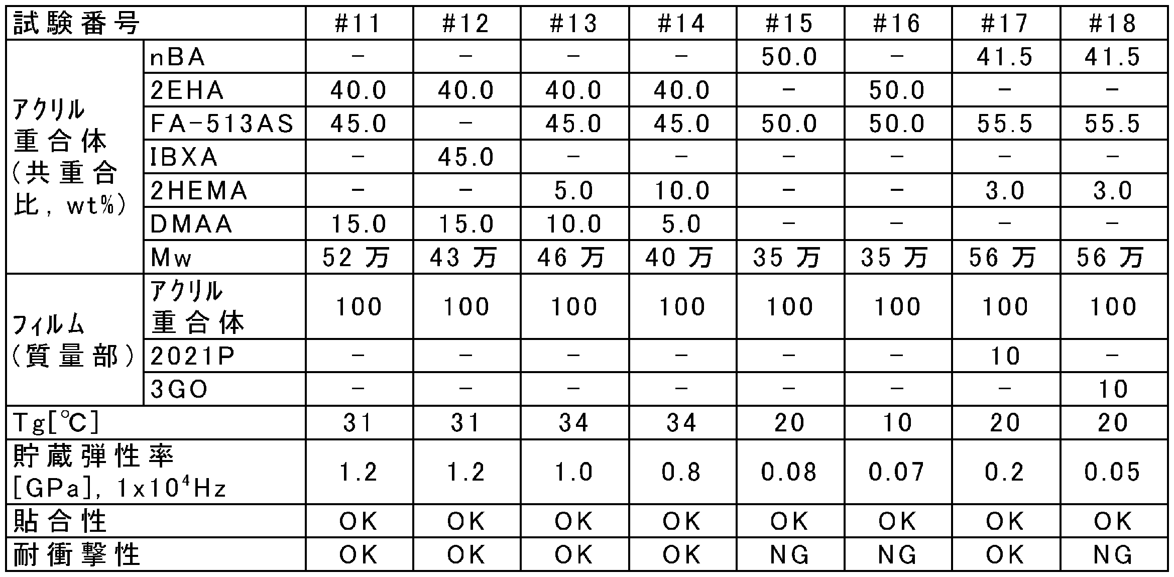
表1及び表2に示されるように、0~35℃のガラス転移温度、及び、1×10⁴Hzの周波数において0.1~10GPaの貯蔵弾性率を示す衝撃吸収フィルムは、貼合性及び耐衝撃性の両方の点で優れることが確認された。
1…衝撃吸収フィルム、11,12…セパレータ、15…積層フィルム、20…ハウジング、20A…開口、21…背面カバー部、22…側壁部、23…内部プレート部、30…カバーウィンドウ、40…表示パネル、47…偏光フィルム、50…装飾層、60…バッテリー、100…電子機器。
Claims (9)
- アクリル重合体を含み、0~35℃のガラス転移温度、及び、1×10⁴Hzの周波数において0.1~10GPaの貯蔵弾性率を示す、衝撃吸収フィルム。
- 前記アクリル重合体が、脂環式(メタ)アクリレートに由来する単量体単位を有する、請求項1に記載の衝撃吸収フィルム。
- 脂環式エポキシ樹脂を更に含む、請求項1又は2に記載の衝撃吸収フィルム。
- 電子機器用である、請求項1~3のいずれか一項に記載の衝撃吸収フィルム。
- 請求項1~3のいずれか一項に記載の衝撃吸収フィルムを20~30℃において脆性材料部材に貼り付けることを含む、脆性材料部材を備える製品を製造する方法。
- 開口を形成しているハウジングと、
前記開口を塞ぐカバーウィンドウと、
前記カバーウィンドウと対向するように前記ハウジングに収容された表示パネルと、
を備える、電子機器であって、
前記ハウジングが、前記カバーウィンドウとは反対側で前記表示パネルと対向する背面カバー部を有し、
当該電子機器が、
前記カバーウィンドウと前記表示パネルとの間、又は前記背面カバー部と前記表示パネルとの間のうち少なくとも一方に設けられた、請求項1~3のいずれか一項に記載の衝撃吸収フィルムを更に備える、電子機器。 - 前記ハウジング、前記カバーウィンドウ、又はこれらの両方が厚さ500μm以下のガラス基材を有し、前記ガラス基材と前記表示パネルとの間に前記衝撃吸収フィルムが設けられている、請求項6に記載の電子機器。
- 前記表示パネルが有機EL表示パネルである、請求項6又は7に記載の電子機器。
- モバイル電子機器、又は車載電子機器である、請求項6~8のいずれか一項に記載の電子機器。
Priority Applications (1)
| Application Number | Priority Date | Filing Date | Title |
|---|---|---|---|
| PCT/JP2020/036018 WO2022064593A1 (ja) | 2020-09-24 | 2020-09-24 | 衝撃吸収フィルム、脆性材料部材を備える製品を製造する方法、及び電子機器 |
Applications Claiming Priority (1)
| Application Number | Priority Date | Filing Date | Title |
|---|---|---|---|
| PCT/JP2020/036018 WO2022064593A1 (ja) | 2020-09-24 | 2020-09-24 | 衝撃吸収フィルム、脆性材料部材を備える製品を製造する方法、及び電子機器 |
Publications (1)
| Publication Number | Publication Date |
|---|---|
| WO2022064593A1 true WO2022064593A1 (ja) | 2022-03-31 |
Family
ID=80844616
Family Applications (1)
| Application Number | Title | Priority Date | Filing Date |
|---|---|---|---|
| PCT/JP2020/036018 Ceased WO2022064593A1 (ja) | 2020-09-24 | 2020-09-24 | 衝撃吸収フィルム、脆性材料部材を備える製品を製造する方法、及び電子機器 |
Country Status (1)
| Country | Link |
|---|---|
| WO (1) | WO2022064593A1 (ja) |
Citations (7)
| Publication number | Priority date | Publication date | Assignee | Title |
|---|---|---|---|---|
| JP2004263084A (ja) * | 2003-03-03 | 2004-09-24 | Nitto Denko Corp | プラズマディスプレイ用フィルタの直貼り用粘着剤 |
| WO2007029557A1 (ja) * | 2005-09-01 | 2007-03-15 | Mitsubishi Plastics, Inc. | 粘着シート |
| JP2015042708A (ja) * | 2013-08-26 | 2015-03-05 | 日東電工株式会社 | 発泡シート |
| WO2015152334A1 (ja) * | 2014-04-03 | 2015-10-08 | 積水化学工業株式会社 | タッチパネル用層間充填材料及び積層体 |
| JP2016166346A (ja) * | 2010-12-10 | 2016-09-15 | 日立化成株式会社 | 光学用粘着材樹脂組成物、光学用粘着材シート、画像表示装置、光学用粘着材シートの製造方法及び画像表示装置の製造方法 |
| WO2018079732A1 (ja) * | 2016-10-31 | 2018-05-03 | 日立化成株式会社 | 合わせガラス、及び合わせガラスの中間膜用フィルム材 |
| JP2019164294A (ja) * | 2018-03-20 | 2019-09-26 | 日立化成株式会社 | 画像表示装置、光硬化性樹脂組成物、及びフィルム材 |
-
2020
- 2020-09-24 WO PCT/JP2020/036018 patent/WO2022064593A1/ja not_active Ceased
Patent Citations (7)
| Publication number | Priority date | Publication date | Assignee | Title |
|---|---|---|---|---|
| JP2004263084A (ja) * | 2003-03-03 | 2004-09-24 | Nitto Denko Corp | プラズマディスプレイ用フィルタの直貼り用粘着剤 |
| WO2007029557A1 (ja) * | 2005-09-01 | 2007-03-15 | Mitsubishi Plastics, Inc. | 粘着シート |
| JP2016166346A (ja) * | 2010-12-10 | 2016-09-15 | 日立化成株式会社 | 光学用粘着材樹脂組成物、光学用粘着材シート、画像表示装置、光学用粘着材シートの製造方法及び画像表示装置の製造方法 |
| JP2015042708A (ja) * | 2013-08-26 | 2015-03-05 | 日東電工株式会社 | 発泡シート |
| WO2015152334A1 (ja) * | 2014-04-03 | 2015-10-08 | 積水化学工業株式会社 | タッチパネル用層間充填材料及び積層体 |
| WO2018079732A1 (ja) * | 2016-10-31 | 2018-05-03 | 日立化成株式会社 | 合わせガラス、及び合わせガラスの中間膜用フィルム材 |
| JP2019164294A (ja) * | 2018-03-20 | 2019-09-26 | 日立化成株式会社 | 画像表示装置、光硬化性樹脂組成物、及びフィルム材 |
Similar Documents
| Publication | Publication Date | Title |
|---|---|---|
| KR102323386B1 (ko) | 점착제 부착 수지 필름 및 그것을 이용한 광학 적층체 | |
| JP6048297B2 (ja) | 光学積層体及びそれを用いた表示装置 | |
| CN101398501B (zh) | 偏振板、其制造方法、光学薄膜以及图像显示装置 | |
| KR101114924B1 (ko) | 프라이머 코팅 조성물, 이를 포함하는 광학 필름 및 이를 포함하는 편광판 | |
| JP6346090B2 (ja) | タッチセンシティブディスプレイ | |
| JP2018055098A (ja) | 表示装置用ウィンドウおよび表示装置 | |
| CN113015928B (zh) | 光学层叠体和具备该光学层叠体的图像显示装置 | |
| JP6206070B2 (ja) | 粘着剤付き樹脂フィルム及びそれを用いた光学積層体 | |
| CN101487912A (zh) | 偏振板、其制造方法、光学薄膜及图像显示装置 | |
| JP2007332341A5 (ja) | ||
| JP2007212995A5 (ja) | ||
| KR101025466B1 (ko) | 편광판, 그 제조 방법, 광학 필름 및 화상 표시 장치 | |
| JP2017211433A (ja) | 偏光フィルム、粘着剤層付き偏光フィルム、及び画像表示装置 | |
| KR102505686B1 (ko) | 광학 적층체 및 액정 표시 장치 | |
| JP7462597B2 (ja) | 円偏光板、光学積層体及び画像表示装置 | |
| JP6043315B2 (ja) | 偏光子保護フィルム、その製造方法、偏光板、光学フィルムおよび画像表示装置 | |
| KR102230902B1 (ko) | 활성 에너지선 중합성 수지 조성물 및 적층체 | |
| JP7447404B2 (ja) | 粘着シート、バックライトユニット及び液晶表示装置 | |
| JPWO2017047408A1 (ja) | 複合偏光板及びそれを用いた液晶パネル | |
| KR102063207B1 (ko) | 점착필름, 이를 포함하는 광학부재 및 이를 포함하는 광학표시장치 | |
| WO2022064593A1 (ja) | 衝撃吸収フィルム、脆性材料部材を備える製品を製造する方法、及び電子機器 | |
| JP2016212443A (ja) | 光学フィルム積層体及びその製造方法 | |
| JP6943081B2 (ja) | 粘着剤組成物、粘着シートおよび積層体 | |
| CN116323847B (zh) | 偏振板及图像显示装置 | |
| TWI621676B (zh) | 黏著劑組成物、黏著層、光學層合物及電子裝置 |
Legal Events
| Date | Code | Title | Description |
|---|---|---|---|
| 121 | Ep: the epo has been informed by wipo that ep was designated in this application |
Ref document number: 20955187 Country of ref document: EP Kind code of ref document: A1 |
|
| NENP | Non-entry into the national phase |
Ref country code: DE |
|
| 122 | Ep: pct application non-entry in european phase |
Ref document number: 20955187 Country of ref document: EP Kind code of ref document: A1 |
|
| NENP | Non-entry into the national phase |
Ref country code: JP |