WO2022059690A1 - 電動パワーステアリング装置 - Google Patents
電動パワーステアリング装置 Download PDFInfo
- Publication number
- WO2022059690A1 WO2022059690A1 PCT/JP2021/033850 JP2021033850W WO2022059690A1 WO 2022059690 A1 WO2022059690 A1 WO 2022059690A1 JP 2021033850 W JP2021033850 W JP 2021033850W WO 2022059690 A1 WO2022059690 A1 WO 2022059690A1
- Authority
- WO
- WIPO (PCT)
- Prior art keywords
- electric power
- power steering
- connector
- steering device
- harness
- Prior art date
- Legal status (The legal status is an assumption and is not a legal conclusion. Google has not performed a legal analysis and makes no representation as to the accuracy of the status listed.)
- Ceased
Links
Images
Classifications
-
- B—PERFORMING OPERATIONS; TRANSPORTING
- B62—LAND VEHICLES FOR TRAVELLING OTHERWISE THAN ON RAILS
- B62D—MOTOR VEHICLES; TRAILERS
- B62D5/00—Power-assisted or power-driven steering
- B62D5/04—Power-assisted or power-driven steering electrical, e.g. using an electric servo-motor connected to, or forming part of, the steering gear
Definitions
- the present invention relates to an electric power steering device that assists steering operation force by the rotational force of an electric motor.
- Patent Document 1 As a conventional electric power steering device of this type, the one described in Patent Document 1 below is known.
- This electric power steering device has a pinion shaft to which the rotational operation force of the steering wheel is transmitted, a torque sensor that detects the steering force from the twist of the torsion bar provided on the pinion shaft, and rack teeth that mesh with the pinion shaft.
- An electric motor that assists the steering force applied to the steering wheel via the formed rack bar and an ECU casing that houses the electronic control unit that drives and controls the electric motor are provided, and one end thereof is connected to the torque sensor. It comprises a connector to which the other end of the wire harness is connected.
- a portion in the middle between the torque sensor and the connector is fastened and fixed to the cylindrical rack bar housing by a fastening band to reduce the influence of vehicle vibration and the like.
- the present invention has been devised in view of the conventional technical problems described in Patent Document 1, and defines a bending direction and the like for a portion from a fixed portion of a wire harness to a connector by the fixed portion.
- One of the purposes is to provide an electric power steering device capable of forming a drip loop and suppressing the ingress of water into the connector.
- the first housing portion is provided on the upper side in the vertical direction of the peripheral wall of the second housing portion
- the ECU casing is located on the lower side in the vertical direction of the peripheral wall of the second housing portion.
- the fixing portion provided at a position separated from the first housing portion in the longitudinal direction of the housing portion and fixing the wire harness to the second housing is such that the protruding piece is on the lower side in the vertical direction of the peripheral wall of the second housing portion. It is specified that a part of the wire harness provided between the fixing portion and the connector is provided at a position opposite to the first housing portion and is vertically lower than the position of the connector. It is characterized by.
- the drip loop can be formed by defining the bending direction of the wire harness by the fixing portion.
- FIG. B is a sectional view taken along line BB of A.
- FIG. B shows the uneven part formed on the outer peripheral surface of the corrugated tube provided in this embodiment, and the inner peripheral surface of a band of a clip, respectively.
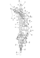
- FIG. 1 is a front view showing a main part of the electric power steering device according to the embodiment of the present invention
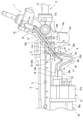
- FIG. 2 is an enlarged view of a main part of FIG.
- the electric power steering device includes a steering mechanism 1 that transmits steering force from the driver and a steering assist mechanism 2 that assists the driver in steering operation.
- the steering mechanism 1 mechanically connects a steering wheel (not shown) arranged in the driver's cab of the vehicle and two steering wheels which are the front wheels of the vehicle.
- the steering mechanism 1 has a steering shaft 5 having an input shaft 3 to which rotational force from the steering wheel is transmitted, an output shaft 4 which is a pinion shaft connected to the input shaft 3 via a torsion bar (not shown), and a steering shaft 5.
- a transmission mechanism 6 for transmitting the rotation of the steering shaft 5 to the steering wheel is provided.
- the steering mechanism 1 has a torque sensor 7 that detects the steering force from the twist of the torsion bar.
- the torque sensor 7 is a general one, and is adapted to convert the twist of the torsion bar into an electric signal and output the electric signal to the electronic control unit 21 described later via the wire harness 8. Further, the torque sensor 7 has a pair of sensor connector portions (not shown) to which one end portion (upper end portion) of the wire harness 8 is connected.
- the output shaft 4 and the torque sensor 7 are housed inside a large-diameter cylindrical first housing portion 10 that constitutes a part of the housing 9 described later, and the sensor connector portion is an outer peripheral wall of the first housing portion 10. It is provided in.
- the first housing portion 10 is formed of a metal material such as an aluminum alloy material.
- the transmission mechanism 6 is a rack and pinion mechanism (rack & pinion) including a pinion (not shown) provided on the outer periphery of the output shaft 4 and a rack (not shown) provided on the outer periphery of the rack bar 12 which is a steering shaft. ⁇ It is composed of gears).
- rack & pinion rack and pinion mechanism
- Both ends of the rack bar 12 are connected to the corresponding steering wheels via a tie rod (not shown) and two knuckle arms, respectively.
- the rack bar 12 is provided so as to be movable in the axis P direction of the rack bar 12 in the second housing portion 11 which is a cylindrical steering shaft housing forming a part of the housing 9.
- the rack bar 12 can be connected to a first ball joint and a second ball joint, which are not shown, at both end portions 12a and 12b, which are a pair of axial end portions of the rack bar 12.
- the rack bar 12 is made of a metal material, and has a steering shaft main body that is substantially columnar and has a spiral groove shape formed on the outer peripheral surface of the steering shaft main body. It is provided with a groove 12c.
- the steering shaft ball screw groove 12c is formed in a spiral groove shape from the axial center position of the rack bar 12 to the vicinity of one end portion 12a of the rack bar 12 by rolling. That is, the steering shaft ball screw groove 12c is formed in a spiral groove shape from the axial center position of the rack bar 12 to the portion exposed from one end portion 11a of the second housing portion 11.
- the steering shaft ball screw groove 12c constitutes a ball screw mechanism in which a plurality of balls circulate between the nut and the nut ball screw groove having the same spiral groove shape, which will be described later.
- the second housing portion 11 is formed in a cylindrical shape, for example, from an aluminum alloy material, like the first housing portion 10, and is integrally molded with the first housing portion 10, for example, by casting. Further, the second housing portion 11 is integrally provided with a pair of block-shaped first and second brackets 13a and 13b fixed to a vehicle body (not shown) by bolts on both end portions 11a and 11b in the axial direction. .. Bolt insertion holes 13c and 13d through which bolts are inserted are formed through the brackets 13a and 13b.
- the housing 9 is composed of the first housing portion 10 and the second housing portion 11.
- Reinforcing ribs 14 are integrally provided along the axial direction on the lower side of the second housing portion 11 in the vertical direction.
- the reinforcing rib 14 is formed in an elongated plate shape, and is extended from one end 11a of the second housing portion 11 to the vicinity of the second bracket 13b on the other end 11b side.
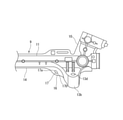
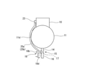
- FIG. 3 is a partially enlarged view of the housing.
- a fixing portion 15 is provided between the second bracket 13b and the reinforcing rib 14.
- the fixing portion 15 is provided in a projecting piece 16 projecting downward in the vertical direction from a part of the reinforcing rib 14 near the bracket 13, a mounting hole 17 formed through substantially the center of the projecting piece 16, and a mounting hole 17. It is composed of a clip 18 described later, which is inserted and anchored, and a clip 18 described later.
- the projecting piece 16 is formed in a substantially elliptical shape when viewed from the front of FIG. 3, and is provided extending from the edge of the reinforcing rib 14 to the side edge of the second bracket 13 along the longitudinal direction, and is the same as the reinforcing rib 14. It is formed in the shape of a thin plate.
- the mounting hole 17 is formed in an elongated elongated hole shape, and is formed in an inclined shape in the lower right direction in FIG. 3 from the upper end 17a to the lower end 17b on the second housing portion 11 side.
- the clip 18 is attached in the middle of the wire harness 8 in the longitudinal direction, and the specific structure and the like will be described later.
- the steering assist mechanism 2 includes an electric motor 20 which is an electric actuator that applies steering force to the steering mechanism 1.
- the electric motor 20 includes a cylindrical motor housing 20a arranged in parallel with the axial direction of the second housing portion 11, and a plurality of parts such as an unexpected rotor, stator, and magnet housed inside the motor housing 20a. And have.
- the electric motor 20 is linked to the rack bar 12 via a transmission mechanism 6, and rotationally drives a nut (not shown) to rotate the rack bar 12 in the axial direction as the nut rotates. ..
- the transmission mechanism 6 is linked to the rack bar 12 by connecting an input pulley fixed to the outer periphery of the tip of the output shaft of the electric motor 20 and an output pulley fixed to the outer periphery of the rack bar 12 via a belt. ing.
- a ball screw mechanism which is a speed reducer, is provided between the output pulley and the rack bar 12.
- the ball screw mechanism has a general structure, and is provided on the steering shaft ball screw groove 12c provided on the outer peripheral surface of the rack bar 12 and the inner peripheral surface of the nut body forming an annular shape of the nut, as described above. It is provided with a nut ball screw groove (not shown) and a plurality of balls circulating between these ball screw grooves.
- the steering shaft ball screw groove 12c is formed in a spiral groove shape, and a spiral ball is formed between the screw groove-shaped nut ball screw groove formed on the inner peripheral surface of the nut body into which the rack bar 12 is inserted. Form a circulation passage.
- an electronic control unit (ECU) 21 which is an electronic control unit for controlling the drive of the electric motor 20 is integrally provided on one end side in the axial direction of the electric motor 20.
- the electronic control unit 21 has a function of storing and executing various control processes, and drives the electric motor 20 based on a steering angle signal from a steering angle sensor (not shown) and a steering torque signal from a torque sensor 7. It is designed to be controlled.
- the electronic control unit 21 includes a substantially cylindrical ECU casing 21a arranged in series with the motor housing 20a, and a plurality of electronic components such as a circuit board and a capacitor housed inside the ECU casing 21a. ..
- the ECU casing 21a is integrally formed of, for example, a synthetic resin material in a bottomed cylindrical shape, and one end in the axial direction is coupled to the motor housing 20a by a coupling means such as a bolt. Further, a connector 22 to which the other end of the wire harness 8 is connected is provided at the other end of the ECU casing 21a in the axial direction.
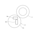
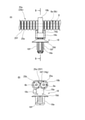
- FIG. 4 is a schematic view of the first and second connector portions as viewed from the direction of arrow A in FIG.
- the connector 22 is composed of a pair of first and second connector portions 22a and 22b corresponding to the pair of first and second harnesses 8a and 8b described later of the wire harness 8.
- the first and second connector portions 22a and 22b are each formed in a substantially rectangular shape in a front view, and the first connector is arranged on the upper side in the vertical direction, that is, on the side of the second housing portion 11.
- the portion 22a is formed in a horizontally long cross section extending horizontally in a direction orthogonal to the axis P of the rack bar 12.
- the second connector portion 22b arranged vertically below the first connector portion 22a is formed in a vertically elongated shape extending in the vertical vertical direction orthogonal to the axis P direction of the rack bar 12.
- the wire harness 8 is composed of a pair of first harness 8a and second harness 8b in order to provide so-called redundancy in case of failure or trouble of the torque sensor 7 and the electronic control unit 21. Further, the first harness 8a and the second harness 8b are provided with sensor connectors and male terminals 23, 24a, 24b connected to the first and second connector portions 22a, 22b, respectively, at both ends in the longitudinal direction. ing. That is, one first terminal 23 is provided at one end of the first and second harnesses 8a and 8b on the torque sensor 7 side, and two at the other end of each of the first and second harnesses 8a and 8b. The second and third terminals 24a and 24b are provided. The second and third terminals 24a and 24b are connected to the first and second connector portions 22a and 22b, respectively.
- the first and second harnesses 8a and 8b are each covered with the first and second corrugated tubes 25a and 25b, respectively.
- FIG. 5A is a side view showing a state in which the clip is attached to the corrugated tube
- FIG. B is a sectional view taken along line BB of A
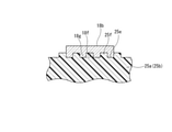
- FIG. 6 is formed on the outer peripheral surface of the corrugated tube and the inner peripheral surface of the band of the clip. It is the schematic which shows the uneven part.
- Each of the corrugated tubes 25a and 25b has a well-known structure, and as shown in FIGS. 5 and 6, bellows-shaped uneven portions 25e and 25f are formed on the outer periphery thereof so that they can be freely bent and deformed.
- the first and second harnesses 8a and 8b are covered with the first and second corrugated tubes 25a and 25b, or for convenience, the first and second harnesses 8a and 8b are the first and second corrugated tubes.
- Each of the corrugated tubes 25a and 25b described as 25a and 25b is attached with the clip 18 which is inserted into and anchored in the mounting hole 17 of the projecting piece 16.
- the clip 18 is composed of a clip body 18a made of synthetic resin and a flexible fastening band (binding band) 18b provided on the clip body 18a.
- the clip main body 18a extends from the head portion 18c that supports the fastening band 18b so as to be retractable, the flat flange portion 18d integrally provided at the lower end of the figure of the head portion 18c, and the lower end of the flange portion 18d. It is composed of a leg portion 18e to be inserted into the mounting hole 17 and a leg portion 18e.
- the leg portion 18e is formed in an substantially oval shape with a cross section substantially the same as the elongated hole shape of the mounting hole 17, and has a plurality of claw portions 18f that can be bent and deformed on both side surfaces. Therefore, when the leg portion 18e is inserted into the mounting hole 17, each claw portion 18f is flexed and deformed inward, and when the leg portion 18e is inserted into the mounting hole 17 to the maximum, the leg portion 18e elastically returns to the original shape and expands outward to the flange. In cooperation with the portion 18d, it is anchored to the opening edge of the mounting hole 17.
- the fastening band 18b is provided at the upper end of the head 18c so as to wind the outer peripheral surfaces of the two first and second corrugated tubes 25a and 25b and bind them in a parallel state. Further, as shown in FIG. 6, on the inner surface of the fastening band 18b, uneven portions 18f and 18g that can be fitted to the uneven portions 25e and 25f of the corrugated tubes 25a and 25b are formed.
- the clip 18 when the clip 18 is inserted into the mounting hole 17 and anchored, the clip 18 is inclined downward from the second housing portion 11 side toward the bracket 13 according to the inclination angle of the mounting hole 17. Will be placed.
- the lengths of the corrugated tubes 25a and 25b from the fixing portion 15 to the first and second connector portions 22a and 22b are set to be sufficiently longer than the linear length so that the corrugated tubes 25a and 25b can be bent and deformed due to bending. It has become.
- the arrangement configuration of the portion between the fixing portion 15 and the first and second connector portions 22a and 22b is defined by the fixing portion 15 which is a stopping point, respectively.
- the clip 18 since the clip 18 is arranged in an inclined shape along the inclination angle of the inclined mounting hole 17 of the fixing portion 15, the first corrugated tube 25a and the second corrugated tube 25b have a handling angle of the clip 18. It is defined to be inclined downward from the position in the vertical direction, and is bent and deformed so as to rise in an inclined manner from the lowest portions 25c and 25d in the directions of the connector portions 22a and 22b, respectively. That is, the lowermost portions 25c and 25d are at positions sufficiently lower than the positions of the connector portions 22a and 22b, whereby a drip loop is formed.
- the length L1 between the fixed portion 15 and the respective connector portions 22a and 22b is formed to be longer than the length L2 from the fixed portion 15 to the sensor connector (terminal 23). Has been done. Therefore, it becomes easy to form the above-mentioned drip loop between the fixing portion 15 and the connector portions 22a and 22b.
- FIG. 7 is a schematic view showing a state in which the corrugated tube is in contact with the second housing from the fixed portion to the sensor connector.
- a part of the portion from the fixing portion 15 of the first and second corrugated tubes 25a and 25b to the sensor connector portion (first terminal 23) of the torque sensor 7 is the second housing portion 11. It is in contact with the arc-shaped outer surface while being deformed in a curved shape.
- the contact portion 11b of the second housing portion 11 guides the intermediate portions of the first and second corrugated tubes 25a and 25b toward the fixed portion 15.
- the second corrugated tube 25b between the fixing portion 15 and the connector portions 22a and 22b is formed longer than the first corrugated tube 25a and is arranged vertically below the first corrugated tube 25a. Therefore, since the first corrugated tube 25a and the second corrugated tube 25b are in a state of being separated from each other, interference due to vibration or the like is suppressed.
- the portion extending from the fixing portion 15 of the first and second corrugated tubes 25a and 25b toward the respective connector portions 22a and 22b is orthogonal to the vertical direction component (arrow A) and the vertical direction.
- the fixed portion 15 When divided into a horizontal component (arrow B) parallel to the second housing portion 11, the fixed portion 15 has a downwardly inclined arrow C component between the arrow A component and the arrow B component, which is the maximum.
- the shape On the side of each of the connector portions 22a and 22b from the lowermost portions 25c and 25d facing downward, the shape is inclined upward toward the respective connector portions 22a and 22b.
- the portion extending in the direction of the torque sensor 7 from the fixed portion 15 of the first and second corrugated tubes 25a and 25b is a horizontal component (arrow C) orthogonal to the vertical component.
- the portion extending in the direction of the torque sensor 7 is an upwardly inclined arrow between the arrow C component and the arrow D component from the fixed portion 15 side toward the torque sensor 7. It is an E component.
- the basic operation of the electric power steering device is that when the driver rotates the steering wheel, the input shaft 3 rotates and the torsion bar is twisted, and the elastic force of the torsion bar generated by the rotation causes the output shaft 4 to rotate. ..
- the rotary motion of the output shaft 4 is converted into a linear motion along the axial direction of the rack bar 12 by the rack & pinion mechanism, and the knuckle arm (not shown) is pushed and pulled in the vehicle width direction via the tie rod. , The direction of the corresponding steering wheel is changed.
- a control signal from the torque sensor 7 that has detected the twist of the torsion bar is transmitted to the electronic control unit 21 via the wire harness 8, and the electronic control unit 21 controls the drive of the electric motor 20 based on this control signal. conduct.
- the rotational driving force of the electric motor 20 is transmitted to the rack bar 12 via a ball screw mechanism or the like to assist the steering force with respect to the steering wheel.
- the fixing portion 15 when the middle of the first and second corrugated tubes 25a and 25b covering the first and second harnesses 8a and 8b is fixed to the second housing portion 11 by the fixing portion 15, the fixing portion 15
- the portion between the connector portions 22a and 22b can be positioned and defined by a fixing portion 15 such as a clip 18 so as to be vertically lower than the positions of the connector portions 22a and 22b. That is, a part of the first and second corrugated tubes 25a and 25b can be bent vertically downward from the connector portions 22a and 22b by the fixing portion 15 to form a so-called drip loop.
- the drip loop can be formed in a short length from the fixed portion 15 of each corrugated tube 25a and 25b to the connector portions 22a and 22b, and the drip loop can be suppressed because complicated bending deformation can be suppressed. It becomes hard to collapse.
- the fixing portion 15 can bind the two corrugated tubes 25a and 25b together via the fastening band 18b of the clip 18, the number of parts can be reduced as compared with the case where the fixing portions 15 are fixed separately.
- the first and second corrugated tubes 25a and 25b connected to each other are connected to each other. Can be separated near each of the connector portions 22a and 22b. Therefore, in particular, interference between the corrugated tubes 25a and 25b due to vibration of the vehicle or the like is suppressed. As a result, it is possible to effectively suppress the interference between the connector portions 22a and 22b due to the interference of the corrugated tubes 25a and 25b, and the damage due to the interference.
- both corrugated tubes 25a and 25b are attached to the clip 18 by engaging and fitting the uneven portions 25e and 25f on the outer peripheral surfaces of the corrugated tubes 25a and 25b and the uneven portions 18f and 18g on the inner peripheral surface of the fastening band 18b. It becomes possible to bond firmly and surely.
- first and second harnesses 8a and 8b of the wire harness 8 are covered with the first and second corrugated tubes 25a and 25b, mud and water splashed up during car washing and vehicle running can be removed. Direct adhesion can be suppressed.
- the protruding piece 16 of the fixing portion 15 can be molded together with the first and second housing portions 10 and 11 and the reinforcing rib 14 at the time of casting the housing 9, the molding work is also easy. Further, the protruding piece 16 can contribute to the improvement of the rigidity of the first housing portion 10 in cooperation with the reinforcing rib 14.
- each of the corrugated tubes 25a and 25b has a short length, and complicated bending deformation is suppressed, so that the shape of the drip loop is not easily deformed.
- the portions between the fixing portion 15 and the sensor connector are the vertical arrow C component and the horizontal arrow D. It extends toward the sensor connector side along the inclined arrow E component between the components. Therefore, the corrugated tubes 25a and 25b from the sensor connector to the fixing portion 15 can be easily aligned with the abutting portion 11d of the second housing portion 11 along the abutting portion 11d of the second housing portion 11.
- the present invention is not limited to the configuration of the above embodiment, and for example, the wire harness 8 may be one, and therefore, the connector 22 on the electronic control unit 21 side can also be one. Is.
- a pinion shaft to which the rotational force of the steering wheel is transmitted, a torque sensor that detects the steering force from the twist of the torsion bar provided on the pinion shaft, and rack teeth that mesh with the pinion shaft are formed.
- An electric power steering device including a housing having a tubular second housing portion for accommodating the rack bar, and a fixing portion provided in the housing and fixedly supporting a portion in the middle of the wire harness.
- the first housing portion is provided on the upper side in the vertical direction of the peripheral wall of the second housing portion, and the ECU casing is located on the lower side in the vertical direction of the peripheral wall of the second housing portion.
- the fixing portion is provided at a position separated from the first housing portion in the longitudinal direction of the above, and a part of the fixing portion is provided at a position opposite to the first housing portion on the lower side in the vertical direction of the peripheral wall of the second housing portion. It is specified that a part of the wire harness held between the fixing portion and the connector is vertically lower than the position of the connector.
- a part between the fixing portion and the connector is vertically oriented from the position of the connector by the fixing portion. It is specified to be on the lower side.
- a part of the wire harness is bent vertically downward from the connector to form a so-called drip loop. Therefore, since the water droplets flowing down from the torque sensor side along the outer surface of the wire harness drip from the drip loop, it is possible to suppress the intrusion into the connector.
- the peculiar formation position of the fixed portion with respect to the second housing portion and the shape definition of the fixed portion with respect to the wire harness cause a part of the wire harness to be flexed and deformed to form a drip loop. It is easy and advantageous in terms of cost.
- the fixing portion is attached to the wire harness, a protrusion piece integrally protruding radially outward from the outer surface of the second housing part, a mounting hole formed through the protruding piece, and the mounting portion.
- the second housing portion has a contact portion where a portion between the fixing portion and the first housing portion of the wire harness abuts along the outer surface shape of the second housing portion, and the contact portion has the contact portion. A portion in the middle of the wire harness is guided in the direction of the protruding piece.
- the portion in the middle of the wire harness can be guided in the direction of the protruding piece by the contact portion of the second housing portion, the work of fixing the wire harness with the protruding piece becomes easy.
- the fixing portion is attached to the wire harness, a protrusion piece integrally protruding radially outward from the outer surface of the second housing part, a mounting hole formed through the protruding piece, and the mounting portion. It has a clip that is inserted into the hole and secures the wire harness to the protrusion.
- the mounting hole is formed in an elongated hole extending in an inclined direction from one end in the vicinity of the second housing portion in a direction away from the second housing portion.
- the mounting hole is formed into an elongated hole extending in an inclined direction from one end near the second housing portion in a direction away from the second housing portion, a clip inserted into the mounting hole is also formed. It is arranged in an inclined shape along the shape of the mounting hole.
- the wire harness extending from the fixed portion toward the connector can be forcibly oriented vertically downward in the direction opposite to the torque sensor by a clip through the mounting hole. Therefore, the portion of the wire harness on the connector side can form a drip loop located below the connector.
- the fixing portion side is in the vertical direction. It is inclined downward between the component and the horizontal component, and is inclined upward from the maximum downward position toward the connector on the connector side.
- the aspect of the present invention it becomes possible to form a drip loop within a short length of the wire harness from the clip to the connector, and complicated bending is suppressed so that the drip loop does not easily collapse.
- the wire harness has two first harnesses and a second harness.
- the fixing portion binds the first harness and the second harness together via a fastening band provided on the clip.
- the first harness and the second harness are bundled in a state of being in contact with each other by the clip.
- the second harness is formed longer than the first harness between the fixing portion and the connector, and the second harness is longer than the first harness. Is also located on the lower side in the vertical direction.
- the first harness and the second harness are separated from each other between the fixed portion and the connector, it is possible to suppress mutual interference due to vibration or the like.
- the connector has two first connector portions and a second connector portion corresponding to the first harness and the second harness.
- the first connector portion is arranged on the upper side in the vertical direction with respect to the second connector portion, and has a horizontally long cross section extending in the horizontal direction orthogonal to the axial direction of the rack bar.
- the second connector portion has a vertically long cross section extending in a direction perpendicular to the axial direction of the rack bar.
- the first connector portion and the second connector portion are vertically separated from each other and have different cross-sectional shapes, the first and second harnesses connected to the first connector portion and the second connector portion are connected to each other. It is possible to separate them near each connector. Therefore, in particular, the interference between the harnesses due to the vibration of the vehicle can be suppressed, and the interference between the connector portions due to the interference of the harnesses and the damage due to the interference can be effectively suppressed.
- the length between the fixed portion of the wire harness and the connector is formed to be longer than the length between the fixed portion and the torque sensor.
- the length of the wire harness between the torque sensor and the connector for forming the drip loop in this range is increased by increasing the length between the fixing portion and the connector. Can be secured.
- the wire harness is covered with a corrugated tube in which concave portions and convex portions are alternately formed on the outer peripheral surface.
- the inner peripheral surface of the fastening band has an uneven portion that meshes with and fits into the uneven portion of the corrugated tube.
- the corrugated tube can be firmly and surely bonded to the fastening band by engaging and fitting the uneven portions of the corrugated tube and the fastening band with each other.
- the portion of the wire harness extending in the torque sensor direction from the fixed portion is divided into a vertical component and a horizontal component orthogonal to the vertical component, the portion extending in the torque sensor direction. Has an upward inclination between the vertical component and the horizontal component from the fixed portion side toward the torque sensor.
- the portion from the fixed portion of the wire harness to the torque sensor can be easily routed along the outer surface of the second housing portion.
- the fixing portion is attached to the wire harness, a projecting piece integrally protruding radially outward from the outer surface of the second housing portion, a mounting hole formed through the projecting piece, and the like.
- the clip secures the wire harness to the projecting piece by inserting it into the mounting hole.
- the portion between the fixed portion of the wire harness and the connector is restricted in the direction in which the drip loop is most likely to be formed. Can be done.
Landscapes
- Engineering & Computer Science (AREA)
- Chemical & Material Sciences (AREA)
- Combustion & Propulsion (AREA)
- Transportation (AREA)
- Mechanical Engineering (AREA)
- Power Steering Mechanism (AREA)
Abstract
第1、第2ハウジング部10,11を有するハウジング9と、第1、第2ハーネス部8a、8bを被覆した第1、第2コルゲートチューブ25a、25bを固定支持する固定部15と、を備え、ECUケーシング21aは、軸方向一端部に第1、第2ハーネス部が接続される第1、第2コネクタ部を有し、固定部は、第2ハウジング部の鉛直方向下側の位置に設けられた突出片16と、突出片に形成された取付孔に挿入して係り止めするクリップ18とを有し、固定部と第1、第2コネクタ部との間に有する各コルゲートチューブの一部が各コネクタ部の位置よりも鉛直方向の下側となるように位置決め規定した。 これらの構成によって、ワイヤーハーネスの固定部からコネクタまでの部位を、固定部によって折り曲げ方向を規定してドリップループを形成する。
Description
本発明は、電動モータの回転力によってステアリングの操作力をアシストする電動パワーステアリング装置に関する。
この種の従来の電動パワーステアリング装置としては、以下の特許文献1に記載されたものが知られている。
この電動パワーステアリング装置は、ステアリングホイールの回転操作力が伝達されるピニオン軸と、前記ピニオン軸に設けられたトーションバーの捩れから操舵力を検出するトルクセンサと、前記ピニオン軸と噛み合うラック歯が形成されたラックバーを介して転舵輪に付与する操舵力をアシストする電動モータと、前記電動モータを駆動制御する電子制御部を収容するECUケーシングに設けられて、前記トルクセンサに一端部が接続されたワイヤーハーネスの他端部が接続されるコネクタと、を備えている。
また、前記ワイヤーハーネスは、前記トルクセンサとコネクタとの途中の部位が締結バンドによって円筒状のラックバーハウジングに締め付け固定されて、車両の振動などによる影響を減少させるようになっている。
ところで、前述したパワーステアリング装置は、前述のように、ワイヤーハーネスの途中の部位が締結バンドによってラックバーハウジングに固定されているが、ワイヤーハーネスは、前記締結バンドによる固定箇所から前記コネクタまでの間の部位が直線的な下り傾斜状に形成されている。このため、外部からワイヤーハーネスに付着した洗車水や雨水などの水滴が前記ワイヤーハーネスを伝って締結バンドによる固定箇所からコネクタ方向へ流下して、該コネクタの内部に浸入するおそれがある。
本発明は、前記特許文献1に記載した従来の技術的課題に鑑みて案出されたもので、ワイヤーハーネスの固定部からコネクタまでの部位に対して、前記固定部によって折り曲げ方向などを規定してドリップループを形成し、コネクタへの水の浸入を抑制できる電動パワーステアリング装置を提供することを一つの目的としている。
本発明は、とりわけ、第1ハウジング部は、第2ハウジング部の周壁の鉛直方向上側に設けられ、ECUケーシングは、前記第2ハウジング部の周壁の鉛直方向下側の位置であって、前記第2ハウジング部の長手方向の前記第1ハウジング部から離間した位置に設けられ、ワイヤーハーネスを第2ハウジングに固定する固定部は、突出片が前記第2ハウジング部の周壁の鉛直方向下側の前記第1ハウジング部と反対側の位置に設けられ、前記固定部と前記コネクタとの間に有する前記ワイヤーハーネスの一部が、前記コネクタの位置よりも鉛直方向の下側となるように規定することを特徴としている。
本発明によれば、固定部によってワイヤーハーネスの折り曲げ方向などを規定してドリップループを形成することができる。
以下、本発明に係る電動パワーステアリング装置の実施形態を図面に基づいて詳述する。
図1は本発明の実施形態に係る電動パワーステアリング装置の主要部を示す正面図、図2は図1の要部拡大図である。
電動パワーステアリング装置は、図1に示すように、運転者からの操舵力を伝達する操舵機構1と、運転者の操舵操作を補助する操舵アシスト機構2と、を備えている。
操舵機構1は、車両の運転室内に配置された図示せぬステアリングホイールと車両の前輪である2つの転舵輪とを機械的に連結している。操舵機構1は、ステアリングホイールからの回転力が伝達される入力軸3と、図示せぬトーションバーを介して入力軸3に接続されたピニオン軸である出力軸4と、を有する操舵軸5と、この操舵軸5の回転を転舵輪に伝達する伝達機構6を備えている。
また、操舵機構1は、トーションバーの捩れから操舵力を検出するトルクセンサ7を有している。このトルクセンサ7は、一般的なもので、トーションバーの捩りを電気信号に変換して、この電気信号を後述する電子制御ユニット21にワイヤーハーネス8を介して出力するようになっている。また、トルクセンサ7は、ワイヤーハーネス8の一端部(上端部)が接続される図外の一対のセンサコネクタ部を有している。
出力軸4とトルクセンサ7は、後述するハウジング9の一部を構成する大径円筒状の第1ハウジング部10の内部に収容されており、センサコネクタ部は、第1ハウジング部10の外周壁に設けられている。第1ハウジング部10は、金属材である例えばアルミニウム合金材によって形成されている。
伝達機構6は、出力軸4の外周に設けられた図示せぬピニオンと、転舵軸であるラックバー12の外周に設けられた図示せぬラックと、からなるラック&ピニオン機構(ラック&ピニオン・ギヤ)により構成されている。
ラックバー12の両端は、図示せぬタイロッドおよび2つのナックルアームを介して対応する転舵輪にそれぞれ連結されている。
ラックバー12は、ハウジング9の一部を構成する円筒状の転舵軸ハウジングである第2ハウジング部11内においてラックバー12の軸線P方向へ移動可能に設けられている。ラックバー12は、該ラックバー12の一対の軸方向端部である両端部12a,12bにおいて、図示せぬ第1ボールジョイントおよび第2ボールジョイントとそれぞれ接続可能となっている。ラックバー12は、金属材料によって形成されるとともに、概ね円柱状をなす図外の転舵軸本体部と、この転舵軸本体の外周面に形成された螺旋溝形状をなす転舵軸ボールねじ溝12cと、を備えている。転舵軸ボールねじ溝12cは、転造によってラックバー12の軸方向中央位置からラックバー12の一端部12a付近まで螺旋溝形状に形成されている。つまり、転舵軸ボールねじ溝12cは、ラックバー12の軸方向中央位置から第2ハウジング部11の一端部11aより露出した部位まで螺旋溝形状に形成されている。転舵軸ボールねじ溝12cは、後述するナットの同じく螺旋溝形状のナットボールねじ溝との間で複数のボールが循環するボールねじ機構を構成する。
第2ハウジング部11は、第1ハウジング部10と同じく例えばアルミニウム合金材料によって円筒状に形成されて第1ハウジング部10と例えば鋳造などによって一体成形されている。また、第2ハウジング部11は、軸方向の両端部11a、11b側に図外の車体にボルトによって固定されるブロック状の一対の第1、第2ブラケット13a、13bが一体に設けられている。この各ブラケット13a、13bには、ボルトが挿通されるボルト挿通孔13c、13dが貫通形成されている。
なお、第1ハウジング部10と第2ハウジング部11とによってハウジング9が構成されている。
第2ハウジング部11の鉛直方向下側には、補強リブ14が軸方向に沿って一体に設けられている。この補強リブ14は、細長い板状に形成されて、第2ハウジング部11の一端部11aから他端部11b側の第2ブラケット13b近傍まで延長形成されている。
図3はハウジングの一部拡大図である。
また、図3に示すように、第2ブラケット13bと補強リブ14との間には、固定部15が設けられている。この固定部15は、補強リブ14のブラケット13近傍の一部から鉛直方向下側に突出した突出片16と、該突出片16のほぼ中央に貫通形成された取付孔17と、取付孔17に挿入して係り止めされる後述のクリップ18と、から構成されている。
突出片16は、図3の正面から視てほぼ楕円形状に形成され、補強リブ14の端縁から第2ブラケット13の側端縁まで長手方向に沿って延びて設けられ、補強リブ14と同じ薄い肉厚の板状に形成されている。
取付孔17は、細長い長孔状に形成されて、第2ハウジング部11側の上端17aから下端17bまで図3中右下方向へ傾斜状に形成されている。
クリップ18は、ワイヤーハーネス8の長手方向の途中に取り付けられ、具体的な構造などについては後述する。
操舵アシスト機構2は、図1及び図2に示すように、操舵機構1に操舵力を付与する電動アクチュエータである電動モータ20を備えている。この電動モータ20は、第2ハウジング部11の軸方向と平行に配置された円筒状のモータハウジング20aと、該モータハウジング20aの内部収容された図外のロータやステータ、磁石などの複数の部品と、を有している。電動モータ20は、伝達機構6を介してラックバー12に連係しており、図外のナットを回転駆動して、該ナットの回転に伴いラックバー12を軸方向に移動させるようになっている。
伝達機構6は、電動モータ20の出力軸の先端部外周に固定された入力プーリとラックバー12の外周に固定された出力プーリが、ベルトを介して接続されることでラックバー12と連係されている。そして、出力プーリとラックバー12との間には、減速機であるボールねじ機構が設けられている。ボールねじ機構は、一般的な構造であって、前述したように、ラックバー12の外周面に設けられた転舵軸ボールねじ溝12cと、ナットの環状をなすナット本体の内周面に設けられた図外のナットボールねじ溝と、これらボールねじ溝の間を循環する複数のボールと、を備えている。
転舵軸ボールねじ溝12cは、螺旋溝形状に形成され、ラックバー12が挿入されるナット本体の内周面に形成された螺旋溝形状のナットボールねじ溝との間に、螺旋状のボール循環通路を形成する。
そして、このボール循環通路内を、複数のボールが循環する。ボールは、ラックバー12の軸線P方向においてラックバー12を軸方向に移動させる。
また、電動モータ20の軸方向の一端部側には、該電動モータ20の駆動を制御する電子制御部である電子制御ユニット(ECU)21が一体的に設けられている。この電子制御ユニット21は、各種制御処理を記憶および実行する機能を有し、図示せぬ舵角センサからの舵角の信号やトルクセンサ7からの操舵トルクの信号に基づいて電動モータ20を駆動制御するようになっている。
電子制御ユニット21は、モータハウジング20aと直列に配置されたほぼ円筒状のECUケーシング21aと、該ECUケーシング21aの内部に収容された回路基板やコンデンサなどの複数の電子部品と、を備えている。ECUケーシング21aは、例えば合成樹脂材によって有底円筒状に一体に形成され、軸方向の一端部がモータハウジング20aに例えばボルトなどの結合手段によって結合されている。また、ECUケーシング21aの軸方向の他端部には、ワイヤーハーネス8の他端部が接続されるコネクタ22が設けられている。
図4は図1の矢印A方向から視た第1、第2コネクタ部の概略図である。
コネクタ22は、ワイヤーハーネス8の後述する一対の第1、第2ハーネス8a、8bに対応して一対の第1、第2コネクタ部22a、22bから構成されている。この第1、第2コネクタ部22a、22bは、図4に示すように、それぞれ正面視ほぼ矩形状に形成されており、鉛直方向上側、つまり第2ハウジング部11側に配置された第1コネクタ部22aは、ラックバー12の軸線Pに対して直交する方向へ水平に延びた断面横長形状に形成されている。一方、第1コネクタ部22aより鉛直方向下側に配置された第2コネクタ部22bは、ラックバー12の軸線P方向に対して直交する垂直上下方向に延びた断面縦長形状に形成されている。
ワイヤーハーネス8は、トルクセンサ7と電子制御ユニット21の故障やトラブルなどに対して備えるいわゆる冗長化を図るために、一対の第1ハーネス8aと第2ハーネス8bによって構成されている。また、第1ハーネス8aと第2ハーネス8bは、長手方向の両端部にセンサコネクタや第1、第2コネクタ部22a、22bにそれぞれ接続される雄型の端子23、24a、24bがそれぞれ設けられている。つまり、第1、第2ハーネス8a、8bのトルクセンサ7側の一端部には一つの第1端子23が設けられ、第1、第2ハーネス8a、8bのそれぞれの他端部には2つの第2、第3端子24a、24bが設けられている。この第2、第3端子24a、24bが、第1、第2コネクタ部22a、22bにそれぞれ接続される。
また、第1、第2ハーネス8a、8bは、図1、図2に示すように、それぞれが第1、第2コルゲートチューブ25a、25bによって被覆されている。
図5Aはコルゲートチューブにクリップが取り付けられた状態を示す側面図、同図BはAのB-B線断面図、図6はコルゲートチューブの外周面とクリップのバンドの内周面にそれぞれ形成された凹凸部を示す概略図である。
各コルゲートチューブ25a,25bは、周知の構造であって、図5、図6に示すように、外周に蛇腹状の凹凸部25e、25fが形成されて自由に撓み変形可能になっている。
なお、第1、第2ハーネス8a、8bは、第1、第2コルゲートチューブ25a、25bによって被覆されていることか、便宜上、第1、第2ハーネス8a、8bを第1、第2コルゲートチューブ25a、25bとして説明する
各コルゲートチューブ25a、25bには、突出片16の取付孔17に挿通して係り止めされる前記クリップ18が取り付けられている。
各コルゲートチューブ25a、25bには、突出片16の取付孔17に挿通して係り止めされる前記クリップ18が取り付けられている。
このクリップ18は、図5A,Bに示すように、合成樹脂製のクリップ本体18aと、該クリップ本体18aに設けられた可撓性の締結バンド(結束バンド)18bと、から構成されている。クリップ本体18aは、締結バンド18bを引き出し可能に支持する頭部18cと、該頭部18cの図中下端に一体に設けられた扁平状のフランジ部18dと、該フランジ部18dの下端から延出して取付孔17に挿入される脚部18eと、から構成されている。この脚部18eは、外形が取付孔17の長孔形状とほぼ同じ横断面ほぼ長円形状に形成され、両側面に撓み変形可能な複数の爪部18fを有している。したがって、脚部18eは、取付孔17に挿入されると各爪部18fが内側に撓み変形しつつ取付孔17に最大に挿入されると、各原形状に弾性復帰して外側に拡がってフランジ部18dと協働して取付孔17の開口縁に係り止めされるようになっている。
締結バンド18bは、頭部18cの上端に設けられ、2本の第1、第2コルゲートチューブ25a、25bの外周面を巻回して並列状態に結束するようになっている。また、締結バンド18bの内面には、図6に示すように、各コルゲートチューブ25a、25bの凹凸部25e、25fに嵌合可能な凹凸部18f、18gが形成されている。
クリップ18は、図2に示すように、取付孔17内に挿入して係り止めした際、取付孔17の傾斜角度に倣って第2ハウジング部11側からブラケット13方向に向かって下り傾斜状に配置されることになる。
また、各コルゲートチューブ25a、25bは、固定部15から第1、第2コネクタ部22a、22bまでの長さが直線的な長さよりも十分に長く設定されて撓みによる屈曲変形可能な長さになっている。
そして、それぞれ各コルゲートチューブ25a、25bは、止め点である固定部15によって、特に固定部15と第1、第2コネクタ部22a、22bまで間の部位の取り回し構成が規定される。
すなわち、クリップ18は、固定部15の傾斜状の取付孔17の傾斜角度に沿って傾斜状に配置されていることから、第1コルゲートチューブ25aと第2コルゲートチューブ25bはその取り回し角度がクリップ18位置から鉛直方向下側へ傾斜状に規定され、それぞれ最下位部25c、25dから各コネクタ部22a、22b方向へ傾斜状に立ち上がるように屈曲変形されている。つまり、それぞれの最下位部25c、25dは、各コネクタ部22a、22bの位置よりも十分に低い位置になっており、これによって、ドリップループが形成されている。
また、第1、第2コルゲートチューブ25a、25bは、固定部15から各コネクタ部22a、22b間の長さL1が、固定部15からセンサコネクタ(端子23)までの長さL2よりも長く形成されている。このため、固定部15と各コネクタ部22a、22bとの間に前述したドリップループを形成し易くなる。
図7はコルゲートチューブが固定部からセンサコネクタまでに第2ハウジングに当接している状態を示す概略図である。
第1、第2コルゲートチューブ25a、25bの固定部15からトルクセンサ7のセンサコネクタ部(第1端子23)までの部位は、図7に示すように、その一部が第2ハウジング部11の円弧状外面に沿って湾曲状に変形しつつ当接している。この第2ハウジング部11の当接部11bが、第1,第2コルゲートチューブ25a、25bの途中の部位を固定部15方向へ案内するようになっている。
さらに、固定部15と各コネクタ部22a、22b間における第2コルゲートチューブ25bは、第1コルゲートチューブ25aよりも長く形成されて、第1コルゲートチューブ25aよりも鉛直方向下側に配置されている。したがって、第1コルゲートチューブ25aと第2コルゲートチューブ25bは、互いに離間した状態になっているので例えば振動などによる干渉が抑制される。
また、図2に示すように、第1、第2コルゲートチューブ25a、25bの固定部15から各コネクタ部22a、22b側に延びた部位を、鉛直方向成分(矢印A)とこの鉛直方向と直交する第2ハウジング部11と平行な水平方向成分(矢印B)とに分けたとき、前記固定部15側では矢印A成分と矢印B成分との間の下向き傾斜状の矢印C成分になり、最大下向きの最下位部25c、25dから各コネクタ部22a、22b側では該各コネクタ部22a、22b方向に向かって上向き傾斜状になっている。
一方、図2に示すように、第1、第2コルゲートチューブ25a、25bの固定部15からトルクセンサ7方向に延びた部位を、垂直方向成分(矢印C)と該垂直方向成分と直交する水平方向成分(矢印D)に分けたとき、前記トルクセンサ7方向に延びた部位は、固定部15側からトルクセンサ7方向に向かって矢印C成分と矢印D成分との間の上向き傾斜状の矢印E成分になっている。
〔本実施形態における作用効果〕
電動パワーステアリング装置の基本的な作動は、運転者がステアリングホイールを回転操作すると、入力軸3が回転してトーションバーが捩られ、これにより生じるトーションバーの弾性力によって、出力軸4が回転する。そして、出力軸4の回転運動が上記ラック&ピニオン機構によりラックバー12の軸方向に沿う直線運動に変換され、タイロッドを介して図示せぬナックルアームが車幅方向へと押し引きされることによって、対応した転舵輪の向きが変更される。
〔本実施形態における作用効果〕
電動パワーステアリング装置の基本的な作動は、運転者がステアリングホイールを回転操作すると、入力軸3が回転してトーションバーが捩られ、これにより生じるトーションバーの弾性力によって、出力軸4が回転する。そして、出力軸4の回転運動が上記ラック&ピニオン機構によりラックバー12の軸方向に沿う直線運動に変換され、タイロッドを介して図示せぬナックルアームが車幅方向へと押し引きされることによって、対応した転舵輪の向きが変更される。
また、前記トーションバーの捩りを検出したトルクセンサ7からの制御信号がワイヤーハーネス8を介して電子制御ユニット21に送信され、この制御信号に基づいて電子制御ユニット21が電動モータ20の駆動制御を行う。この電動モータ20の回転駆動力を、ボール螺子機構などを介してラックバー12に伝達して転舵輪に対する操舵力をアシストする。
そして、本実施形態では、第1、第2ハーネス8a、8bを被覆した第1、第2コルゲートチューブ25a、25bの途中を固定部15によって第2ハウジング部11に固定した際、前記固定部15と各コネクタ部22a、22bとの間の部位を、クリップ18などの固定部15によって各コネクタ部22a、22bの位置よりも鉛直方向下側の方向となるように位置決め規定することができる。つまり、固定部15によって第1、第2コルゲートチューブ25a、25bの一部を、各コネクタ部22a、22bより鉛直方向下側に折曲形成して、いわゆるドリップループに形成することができる。
このため、トルクセンサ7側などから第1、第2コルゲートチューブ25a、25bの外面を伝って流下した水滴はドリップループの最下位部25c、25dから滴下する。これによって、第1、第2コネクタ部22a、22b内への水の浸入を効果的に抑制することができる。
特に、固定部15における突出片16の第2ハウジング部11の鉛直方向下側に配置した特異な形成位置と、各コルゲートチューブ25a、25bに対する取付孔17やクリップ18の配置角度による位置決め規定と、によって各コルゲートチューブ25a、25bの一部を屈曲変形させてドリップループを形成するので、この形成作業と構造が簡単であり、コストの点で有利である。
また、各コルゲートチューブ25a、25bの固定部15から各コネクタ部22a、22bまでの短い長さの中でドリップループを形成することが可能になると共に、複雑な屈曲変形を抑制できるのでドリップループが崩れ難くなる。
固定部15は、クリップ18の締結バンド18bを介して2本のコルゲートチューブ25a、25bを一緒に結束できるので、それぞれ別個に固定する場合に比較して部品点数の削減が図れる。
さらに、固定部15によって2本のコルゲートチューブ25a、25bが結束されて横断面ほぼ扁平状になることから、この点でもドリップループの形状が崩れることなく屈曲形状を維持することができる。
また、各コルゲートチューブ25a、25bは、その一部が第2ハウジング部11の当接部11bに沿って接触しながら突出片16方向へ案内されることから、突出片16とクリップ18による第2ハウジング部11に対する固定作業が容易になる。
第1コネクタ部22aと第2コネクタ部22bは、それぞれの位置が互いに上下に離間していると共に、断面形状が異なっていることから、それぞれに接続された第1、第2コルゲートチューブ25a、25bを各コネクタ部22a、22b付近で離間させることができる。このため、特に、車両の振動などによる各コルゲートチューブ25a、25b同士の干渉が抑制される。この結果、該各コルゲートチューブ25a、25bの干渉に伴う各コネクタ部22a、22b間の干渉や、干渉による破損などを効果的に抑制できる。
さらに、各コルゲートチューブ25a、25bの外周面の凹凸部25e、25fと締結バンド18bの内周面の凹凸部18f、18gを、噛み合い嵌合させることで、両コルゲートチューブ25a、25bをクリップ18に強固かつ確実に結合させることが可能になる。
また、ワイヤーハーネス8の第1、第2ハーネス8a、8bは、第1、第2コルゲートチューブ25a、25bによって被覆されていることから、洗車や車両走行中に跳ね上げられた泥や水などの直接的な付着を抑制できる。
固定部15の突出片16は、ハウジング9の鋳造時などに第1、第2ハウジング部10,11や補強リブ14と一緒に成形できるので、その成形作業も容易である。また突出片16は、補強リブ14と協働して第1ハウジング部10の剛性の向上に寄与することができる。
また、第1、第2コルゲートチューブ25a、25bは、前述のように、固定部15から第1、第2コネクタ部22a、22bまでの間の部位が、鉛直方向の矢印A成分と水平方向の矢印B成分との間の傾斜状の矢印C成分から矢印B成分に変向して各コネクタ部22a、22b側に向かって延びている。このため、各コルゲートチューブ25a、25bは、短い長さとなって複雑な屈曲変形が抑制されてドリップループの形が崩れ難くなる。
さらに、第1、第2コルゲートチューブ25a、25bは、前述のように、固定部15からセンサコネクタ(第1端子23)なでの間の部位が垂直方向の矢印C成分と水平方向の矢印D成分との間の傾斜状の矢印E成分に沿ってセンサコネクタ側に向かって延びている。このため、センサコネクタから固定部15までの各コルゲートチューブ25a、25bを第2ハウジング11の当接部11dに無理なく第2ハウジング部11の当接部11dに沿わせることができる。
本発明は、前記実施形態の構成に限定されるものではなく、例えば、ワイヤーハーネス8としては1本であっても良く、したがって、電子制御ユニット21側のコネクタ22も1つにすることも可能である。
さらに、例えば突出片16や取付孔17の形成位置などを変更してワイヤーハーネス8の撓み変形態様を規制してドリップループの形状をさらに変更することも可能である。
以上説明した実施形態に基づく電動パワーステアリング装置としては、例えば、以下に述べる態様のものが考えられる。
その1つの態様として、ステアリングホイールの回転力が伝達されるピニオン軸と、前記ピニオン軸に設けられたトーションバーの捩れから操舵力を検出するトルクセンサと、前記ピニオン軸と噛み合うラック歯が形成されたラックバーと、前記ラックバーを介して転舵輪に付与する操舵力を発生する電動モータと、前記電動モータの出力軸と反対側の位置に配置され、前記電動モータを駆動制御する電子部品を収容するECUケーシングと、前記ECUケーシングに設けられて、前記トルクセンサに一端部が接続されたワイヤーハーネスの他端部が接続されるコネクタと、前記ピニオン軸及びトルクセンサを収容する第1ハウジング部と、前記ラックバーを収容する筒状の第2ハウジング部と、を有するハウジングと、前記ハウジングに設けられ、前記ワイヤーハーネスの途中の部位を固定支持する固定部と、を備えた電動パワーステアリング装置であって、
前記第1ハウジング部は、前記第2ハウジング部の周壁の鉛直方向上側に設けられ、前記ECUケーシングは、前記第2ハウジング部の周壁の鉛直方向下側の位置であって、前記第2ハウジング部の長手方向の前記第1ハウジング部から離間した位置に設けられ、前記固定部は、一部が前記第2ハウジング部の周壁の鉛直方向下側の前記第1ハウジング部と反対側の位置に設けられ、前記固定部と前記コネクタとの間に有する前記ワイヤーハーネスの一部が、前記コネクタの位置よりも鉛直方向の下側となるように規定する。
前記第1ハウジング部は、前記第2ハウジング部の周壁の鉛直方向上側に設けられ、前記ECUケーシングは、前記第2ハウジング部の周壁の鉛直方向下側の位置であって、前記第2ハウジング部の長手方向の前記第1ハウジング部から離間した位置に設けられ、前記固定部は、一部が前記第2ハウジング部の周壁の鉛直方向下側の前記第1ハウジング部と反対側の位置に設けられ、前記固定部と前記コネクタとの間に有する前記ワイヤーハーネスの一部が、前記コネクタの位置よりも鉛直方向の下側となるように規定する。
この発明の態様によれば、ワイヤーハーネスの途中を固定部で第2ハウジング部に固定支持した際に、固定部とコネクタとの間の一部を、前記固定部によってコネクタの位置よりも鉛直方向下側となるように規定した。これによって、ワイヤーハーネスの一部は、コネクタより鉛直方向下側に折り曲げられていわゆるドリップループが形成される。このため、トルクセンサ側からワイヤーハーネスの外面を伝って流下した水滴がドリップループから滴下することから、コネクタ内への浸入を抑制できる。
特に、固定部の第2ハウジング部に対する特異な形成位置と、ワイヤーハーネスに対する固定部の形状規定と、によってワイヤーハーネスの一部の撓み変形させてドリップループを形成するので、この形成作業と構造が簡単であり、コストの点で有利である。
さらに好ましくは、前記固定部は、前記第2ハウジング部の外面から径方向外側へ一体に突出した突出片と、該突出片に貫通形成された取付孔と、前記ワイヤーハーネスに取り付けられ、前記取付孔に挿入して係り止め可能なクリップと、を有し、
前記第2ハウジング部は、前記ワイヤーハーネスの前記固定部と第1ハウジング部との間の部位が第2ハウジング部の外面形状に沿って当接する当接部を有し、前記当接部が前記ワイヤーハーネスの途中の部位を前記突出片の方向へ案内する。
前記第2ハウジング部は、前記ワイヤーハーネスの前記固定部と第1ハウジング部との間の部位が第2ハウジング部の外面形状に沿って当接する当接部を有し、前記当接部が前記ワイヤーハーネスの途中の部位を前記突出片の方向へ案内する。
この発明の態様によれば、第2ハウジング部の当接部によって、ワイヤーハーネスの途中の部位を突出片方向へ案内することができるので、突出片でのワイヤーハーネスの固定作業が容易になる。
さらに好ましくは、前記固定部は、前記第2ハウジング部の外面から径方向外側へ一体に突出した突出片と、該突出片に貫通形成された取付孔と、前記ワイヤーハーネスに取り付けられ、前記取付孔に挿入して前記突出片に前記ワイヤーハーネスを固定するクリップと、を有し、
前記取付孔は、前記第2ハウジング部近傍の一端から第2ハウジング部から離間する方向へ傾斜状に延びた長孔に形成されている。
前記取付孔は、前記第2ハウジング部近傍の一端から第2ハウジング部から離間する方向へ傾斜状に延びた長孔に形成されている。
この発明の態様によれば、取付孔を第2ハウジング部近傍の一端から第2ハウジング部から離間する方向へ傾斜状に延びた長孔に形成したことから、この取付孔に挿入されるクリップも取付孔の形状に沿って傾斜状に配置される。これによって、固定部からコネクタ方向へ延びたワイヤーハーネスに対して、前記取付孔を介してクリップによってトルクセンサと反対方向の鉛直下方向へ強制的に向きを規定することができる。したがって、ワイヤーハーネスのコネクタ側の部位が、コネクタよりも下方に位置したドリップループを形成できる。
さらに好ましくは、前記ワイヤーハーネスの前記固定部による固定箇所からコネクタ側に延びた部位を、鉛直方向成分と第2ハウジング部に平行な水平方向成分とに分けたとき、前記固定部側では鉛直方向成分と水平方向成分との間の下向き傾斜状になり、最大下向き位置から前記コネクタ側では該コネクタ方向に向かって上向き傾斜状になっている。
この発明の態様によれば、クリップからコネクタまでのワイヤーハーネスの短い長さの中でドリップループを形成することが可能になると共に、複雑な屈曲が抑制されてドリップループが崩れ難くなる。
さらに好ましくは、前記ワイヤーハーネスは、2本の第1ハーネスと第2ハーネスを有し、
前記固定部は、前記クリップに設けられた締結バンドを介して前記第1ハーネスと第2ハーネスを一緒に結束する。
前記固定部は、前記クリップに設けられた締結バンドを介して前記第1ハーネスと第2ハーネスを一緒に結束する。
この発明の態様によれば、クリップによって2本のハーネスを纏めて結束できるので、それぞれ別個に固定する場合に比較して部品点数の削減が図れる。
さらに好ましくは、前記第1ハーネスと第2ハーネスは、前記クリップによって互いに接触した状態で結束されている。
2つのハーネスを接触させることによって並列一体化して横断面ほぼ扁平状になることから、ドリップループの形状が崩れることなく形状を維持することができる。
さらに好ましくは、前記第1ハーネスと第2ハーネスは、前記固定部と前記コネクタとの間で、前記第2ハーネスが前記第1ハーネスよりも長く形成されて、前記第2ハーネスが第1ハーネスよりも鉛直方向下側に配置されている。
この発明の態様によれば、固定部とコネクタとの間では、第1ハーネスと第2ハーネスは互いに離間した状態になっていることから、振動などによる互いの干渉を抑制できる。
さらに好ましくは、前記コネクタは、前記第1ハーネスと第2ハーネスに対応して2つの第1コネクタ部と第2コネクタ部を有し、
前記第1コネクタ部は、前記第2コネクタ部に対して鉛直方向上側に配置されていると共に、前記ラックバーの軸心方向に対して直交する水平方向に延びた断面横長形状になっている一方、
前記第2コネクタ部は、前記ラックバーの軸心方向に対して垂直方向に延びた断面縦長形状になっている。
前記第1コネクタ部は、前記第2コネクタ部に対して鉛直方向上側に配置されていると共に、前記ラックバーの軸心方向に対して直交する水平方向に延びた断面横長形状になっている一方、
前記第2コネクタ部は、前記ラックバーの軸心方向に対して垂直方向に延びた断面縦長形状になっている。
この発明の態様によれば、第1コネクタ部と第2コネクタ部とは、互いに上下に離間していると共に、断面形状が異なっていることから、それぞれに接続された第1、第2ハーネスを各コネクタ部付近で離間させることが可能になる。このため、特に、車両の振動などによる各ハーネス同士の干渉が抑制されると共に、該各ハーネスの干渉に伴う各コネクタ部間の干渉や、干渉による破損なども効果的に抑制できる。
さらに好ましくは、前記ワイヤーハーネスの前記固定部と前記コネクタとの間の長さは、前記固定部と前記トルクセンサとの間の長さよりも長く形成されている。
この発明の態様によれば、トルクセンサとコネクタとの間のワイヤーハーネスのうち、固定部とコネクタとの間の長さを長くすることによって、この範囲でドリップループを形成するための長さを確保できる。
さらに好ましくは、前記ワイヤーハーネスは、外周面に凹部と凸部とが交互に形成されたコルゲートチューブによって被覆され、
前記締結バンドの内周面には、前記コルゲートチューブの凹凸部に噛み合い嵌合する凹凸部を有している。
前記締結バンドの内周面には、前記コルゲートチューブの凹凸部に噛み合い嵌合する凹凸部を有している。
この発明の態様によれば、コルゲートチューブと締結バンドとの互いの凹凸部を噛み合い嵌合させることで、コルゲートチューブを締結バンドに強固かつ確実に結合させることが可能になる。
さらに好ましくは、前記ワイヤーハーネスのうち前記固定部から前記トルクセンサ方向に延びる部位を、鉛直方向成分と該鉛直方向成分と直交する水平方向成分とに分けたとき、前記トルクセンサ方向に延びた部位は、前記固定部側からトルクセンサ方向に向かって鉛直方向成分と水平方向成分との間の上向き傾斜状になっている。
この発明の態様によれば、ワイヤーハーネスの固定部からトルクセンサまでの部位を、第2ハウジング部の外面に沿って無理なく取り回すことができる。
さらに好ましくは、前記固定部は、前記第2ハウジング部の外面から径方向外側へ一体に突出した突出片と、該突出片に貫通形成された取付孔と、前記ワイヤーハーネスに取り付けられて、前記取付孔に挿入可能なクリップと、を有し、
前記クリップは、前記取付孔に挿入することによって前記突出片に前記ワイヤーハーネスを固定する。
前記クリップは、前記取付孔に挿入することによって前記突出片に前記ワイヤーハーネスを固定する。
この発明の態様によれば、ワイヤーハーネスを前記クリップによって突出片に固定支持することによって、ワイヤーハーネスの前記固定部とコネクタとの間の部位を、ドリップループが最も形成し易い方向へ規制することができる。
1…操舵機構、2…操舵アシスト機構、3…入力軸、4…出力軸(ピニオン軸)、5…操舵軸、7…トルクセンサ、8…ワイヤーハーネス、8a…第1ハーネス、8b…第2ハーネス、9…ハウジング、10…第1ハウジング部、11…第2ハウジング部、11b…当接部、15…固定部、16…突出片、17…取付孔、18…クリップ、18a…クリップ本体、18b…締結バンド、21…電子制御ユニット(ECU)、22…コネクタ、22a…第1コネクタ部、22b…第2コネクタ部、23…第1端子、24a…第1端子、24b…第2端子、25a…第1コルゲートチューブ、25b…第2コルゲートチューブ、25c・25d…最下位部、P…ラックバーの軸線。
Claims (12)
- ステアリングホイールの回転力が伝達されるピニオン軸と、
前記ピニオン軸に設けられたトーションバーの捩れから操舵力を検出するトルクセンサと、
前記ピニオン軸と噛み合うラック歯が形成されたラックバーと、
前記ラックバーを介して転舵輪に付与する操舵力を発生する電動モータと、
前記電動モータを駆動制御する電子部品を収容するECUケーシングと、
前記ECUケーシングに設けられて、前記トルクセンサに一端部が接続されたワイヤーハーネスの他端部が接続されるコネクタと、
前記ピニオン軸及びトルクセンサを収容する第1ハウジング部と、前記ラックバーを収容する筒状の第2ハウジング部と、を有するハウジングと、
前記ハウジングに設けられ、前記ワイヤーハーネスの途中の部位を固定支持する固定部と、
を備えた電動パワーステアリング装置であって、
前記第1ハウジング部は、前記第2ハウジング部の周壁の鉛直方向上側に設けられ、
前記ECUケーシングは、前記第2ハウジング部の周壁の鉛直方向下側の位置であって、前記第2ハウジング部の長手方向の前記第1ハウジング部から離間した位置に設けられ、
前記固定部は、一部が前記第2ハウジング部の周壁の鉛直方向下側の前記第1ハウジング部と反対側の位置に設けられ、前記固定部と前記コネクタとの間に有する前記ワイヤーハーネスの一部が、前記コネクタの位置よりも鉛直方向の下側となるように規定することを特徴とする電動パワーステアリング装置。 - 請求項1に記載の電動パワーステアリング装置であって、
前記固定部は、前記第2ハウジング部の外面から径方向外側へ一体に突出した突出片と、該突出片に貫通形成された取付孔と、前記ワイヤーハーネスに取り付けられ、前記取付孔に挿入して係り止め可能なクリップと、を有し、
前記第2ハウジング部は、前記ワイヤーハーネスの前記固定部と第1ハウジング部との間の部位が第2ハウジング部の外面形状に沿って当接する当接部を有し、前記当接部が前記ワイヤーハーネスの途中の部位を前記突出片の方向へ案内することを特徴とする電動パワーステアリング装置。 - 請求項1に記載の電動パワーステアリング装置であって、
前記固定部は、前記第2ハウジング部の外面から径方向外側へ一体に突出した突出片と、該突出片に貫通形成された取付孔と、前記ワイヤーハーネスに取り付けられ、前記取付孔に挿入して前記突出片に前記ワイヤーハーネスを固定するクリップと、を有し、
前記取付孔は、前記第2ハウジング部近傍の一端から第2ハウジング部から離間する方向へ傾斜状に延びた長孔に形成されていることを特徴とする電動パワーステアリング装置。 - 請求項3に記載の電動パワーステアリング装置であって、
前記ワイヤーハーネスの前記固定部による固定箇所からコネクタ側に延びた部位を、鉛直方向成分と第2ハウジング部に平行な水平方向成分とに分けたとき、前記固定部側では鉛直方向成分と水平方向成分との間の下向き傾斜状になり、最大下向き位置から前記コネクタ側では該コネクタ方向に向かって上向き傾斜状になっていることを特徴とする電動パワーステアリング装置。 - 請求項4に記載の電動パワーステアリング装置であって、
前記ワイヤーハーネスは、2本の第1ハーネスと第2ハーネスを有し、
前記固定部は、前記クリップに設けられた締結バンドを介して前記第1ハーネスと第2ハーネスを一緒に結束することを特徴とする電動パワーステアリング装置。 - 請求項5に記載の電動パワーステアリング装置であって、
前記第1ハーネスと第2ハーネスは、前記締結バンドによって互いに接触した状態で結束されていることを特徴とする電動パワーステアリング装置。 - 請求項5に記載の電動パワーステアリング装置であって、
前記第1ハーネスと第2ハーネスは、前記固定部と前記コネクタとの間で、前記第2ハーネスが前記第1ハーネスよりも長く形成されて、前記第2ハーネスが第1ハーネスよりも鉛直方向下側に配置されていることを特徴とする電動パワーステアリング装置。 - 請求項5に記載の電動パワーステアリング装置であって、
前記コネクタは、前記第1ハーネスと第2ハーネスに対応して2つの第1コネクタ部と第2コネクタ部を有し、
前記第1コネクタ部は、前記第2コネクタ部に対して鉛直方向上側に配置されていると共に、前記ラックバーの軸心方向に対して直交する水平方向に延びた断面横長形状になっている一方、
前記第2コネクタ部は、前記ラックバーの軸心方向に対して直交する垂直方向に延びた断面縦長形状になっていることを特徴とする電動パワーステアリング装置。 - 請求項4に記載の電動パワーステアリング装置であって、
前記ワイヤーハーネスの前記固定部と前記コネクタとの間の長さは、前記固定部と前記トルクセンサとの間の長さよりも長く形成されていることを特徴とする電動パワーステアリング装置。 - 請求項5に記載の電動パワーステアリング装置であって、
前記ワイヤーハーネスは、外周面に凹部と凸部とが交互に形成されたコルゲートチューブによって被覆され、
前記締結バンドの内周面には、前記コルゲートチューブの凹凸部に噛み合い嵌合する凹凸部を有することを特徴とする電動パワーステアリング装置。 - 請求項3に記載の電動パワーステアリング装置であって、
前記ワイヤーハーネスのうち前記固定部から前記トルクセンサ方向に延びる部位を、鉛直方向成分と該鉛直方向成分と直交する水平方向成分とに分けたとき、前記トルクセンサ方向に延びた部位は、前記固定部側からトルクセンサ方向に向かって鉛直方向成分と水平方向成分との間の上向き傾斜状になっていることを特徴とする電動パワーステアリング装置。 - 請求項1に記載の電動パワーステアリング装置であって、
前記固定部は、前記第2ハウジング部の外面から径方向外側へ一体に突出した突出片と、該突出片に貫通形成された取付孔と、前記ワイヤーハーネスに取り付けられて、前記取付孔に挿入可能なクリップと、を有し、
前記クリップは、前記取付孔に挿入することによって前記突出片に前記ワイヤーハーネスを固定することを特徴とする電動パワーステアリング装置。
Applications Claiming Priority (2)
| Application Number | Priority Date | Filing Date | Title |
|---|---|---|---|
| JP2020-156062 | 2020-09-17 | ||
| JP2020156062A JP2023162458A (ja) | 2020-09-17 | 2020-09-17 | 電動パワーステアリング装置 |
Publications (1)
| Publication Number | Publication Date |
|---|---|
| WO2022059690A1 true WO2022059690A1 (ja) | 2022-03-24 |
Family
ID=80776031
Family Applications (1)
| Application Number | Title | Priority Date | Filing Date |
|---|---|---|---|
| PCT/JP2021/033850 Ceased WO2022059690A1 (ja) | 2020-09-17 | 2021-09-15 | 電動パワーステアリング装置 |
Country Status (2)
| Country | Link |
|---|---|
| JP (1) | JP2023162458A (ja) |
| WO (1) | WO2022059690A1 (ja) |
Cited By (4)
| Publication number | Priority date | Publication date | Assignee | Title |
|---|---|---|---|---|
| JPWO2024057683A1 (ja) * | 2022-09-14 | 2024-03-21 | ||
| WO2024057987A1 (ja) * | 2022-09-15 | 2024-03-21 | 日立Astemo株式会社 | 操舵装置 |
| WO2024190761A1 (ja) * | 2023-03-15 | 2024-09-19 | 日立Astemo株式会社 | 電動パワーステアリング装置及び電動駆動装置 |
| WO2025049836A1 (en) * | 2023-09-01 | 2025-03-06 | Ppc Broadband, Inc. | Attachment device configured to attach a conduit to a support and having a conduit engagement portion configured to relieve strain on the conduit |
Citations (7)
| Publication number | Priority date | Publication date | Assignee | Title |
|---|---|---|---|---|
| JPH1159472A (ja) * | 1997-08-20 | 1999-03-02 | Toyota Motor Corp | 後輪操舵装置 |
| JP2007242283A (ja) * | 2006-03-06 | 2007-09-20 | Jtekt Corp | コネクタ取付装置 |
| JP2009056943A (ja) * | 2007-08-31 | 2009-03-19 | Nsk Ltd | 電動パワーステアリング装置 |
| JP2013046505A (ja) * | 2011-08-25 | 2013-03-04 | Auto Network Gijutsu Kenkyusho:Kk | ベルト付クランプ及びワイヤハーネス |
| JP2017189034A (ja) * | 2016-04-06 | 2017-10-12 | 株式会社デンソー | 駆動装置、および、これを用いた電動パワーステアリング装置 |
| JP2020011624A (ja) * | 2018-07-19 | 2020-01-23 | 日立オートモティブシステムズ株式会社 | ステアリング装置およびその製造方法 |
| JP2020063771A (ja) * | 2018-10-16 | 2020-04-23 | 大和化成工業株式会社 | 係合部材 |
-
2020
- 2020-09-17 JP JP2020156062A patent/JP2023162458A/ja active Pending
-
2021
- 2021-09-15 WO PCT/JP2021/033850 patent/WO2022059690A1/ja not_active Ceased
Patent Citations (7)
| Publication number | Priority date | Publication date | Assignee | Title |
|---|---|---|---|---|
| JPH1159472A (ja) * | 1997-08-20 | 1999-03-02 | Toyota Motor Corp | 後輪操舵装置 |
| JP2007242283A (ja) * | 2006-03-06 | 2007-09-20 | Jtekt Corp | コネクタ取付装置 |
| JP2009056943A (ja) * | 2007-08-31 | 2009-03-19 | Nsk Ltd | 電動パワーステアリング装置 |
| JP2013046505A (ja) * | 2011-08-25 | 2013-03-04 | Auto Network Gijutsu Kenkyusho:Kk | ベルト付クランプ及びワイヤハーネス |
| JP2017189034A (ja) * | 2016-04-06 | 2017-10-12 | 株式会社デンソー | 駆動装置、および、これを用いた電動パワーステアリング装置 |
| JP2020011624A (ja) * | 2018-07-19 | 2020-01-23 | 日立オートモティブシステムズ株式会社 | ステアリング装置およびその製造方法 |
| JP2020063771A (ja) * | 2018-10-16 | 2020-04-23 | 大和化成工業株式会社 | 係合部材 |
Cited By (9)
| Publication number | Priority date | Publication date | Assignee | Title |
|---|---|---|---|---|
| JPWO2024057683A1 (ja) * | 2022-09-14 | 2024-03-21 | ||
| WO2024057683A1 (ja) * | 2022-09-14 | 2024-03-21 | 日立Astemo株式会社 | 電動駆動装置及び電動パワーステアリング装置 |
| JP7854057B2 (ja) | 2022-09-14 | 2026-04-30 | Astemo株式会社 | 電動駆動装置及び電動パワーステアリング装置 |
| WO2024057987A1 (ja) * | 2022-09-15 | 2024-03-21 | 日立Astemo株式会社 | 操舵装置 |
| JP2024042256A (ja) * | 2022-09-15 | 2024-03-28 | 日立Astemo株式会社 | 操舵装置 |
| JP7801193B2 (ja) | 2022-09-15 | 2026-01-16 | Astemo株式会社 | 操舵装置 |
| WO2024190761A1 (ja) * | 2023-03-15 | 2024-09-19 | 日立Astemo株式会社 | 電動パワーステアリング装置及び電動駆動装置 |
| JP2024130718A (ja) * | 2023-03-15 | 2024-09-30 | 日立Astemo株式会社 | 電動パワーステアリング装置及び電動駆動装置 |
| WO2025049836A1 (en) * | 2023-09-01 | 2025-03-06 | Ppc Broadband, Inc. | Attachment device configured to attach a conduit to a support and having a conduit engagement portion configured to relieve strain on the conduit |
Also Published As
| Publication number | Publication date |
|---|---|
| JP2023162458A (ja) | 2023-11-09 |
Similar Documents
| Publication | Publication Date | Title |
|---|---|---|
| JP2023162458A (ja) | 電動パワーステアリング装置 | |
| US4939867A (en) | Power supplying system for self-driving closure device | |
| JP2008308033A (ja) | 車輪駆動装置 | |
| KR101315666B1 (ko) | 전동식 동력 보조 조향장치의 감속기 및 이를 이용한 전동식 동력 보조 조향장치 | |
| JP5381073B2 (ja) | 車載機器の搭載構造 | |
| US10183692B2 (en) | Driving device | |
| US10071710B2 (en) | Wiper apparatus | |
| US20070235247A1 (en) | Electric power steering device | |
| JP2019006269A (ja) | ステアリング装置 | |
| JP2007242283A (ja) | コネクタ取付装置 | |
| KR101080494B1 (ko) | 브러시형 직류 모터 및 이를 구비한 전동식 조향장치 | |
| JP2006027340A (ja) | 電動パワーステアリング装置 | |
| JP5672935B2 (ja) | 電動パワーステアリング装置 | |
| US20180152011A1 (en) | Wiring harness fixing structure | |
| US12466467B2 (en) | Gear housing and electric assist device | |
| JP7854057B2 (ja) | 電動駆動装置及び電動パワーステアリング装置 | |
| JP5832924B2 (ja) | パワーステアリング装置 | |
| JP2007209126A (ja) | モータ制御装置およびパワーステアリング装置 | |
| JP2009006916A (ja) | 電動パワーステアリング装置 | |
| JP3668562B2 (ja) | ケーブル式ステアリング装置 | |
| JP4379101B2 (ja) | 電動パワーステアリング装置 | |
| JP7417509B2 (ja) | モータユニット | |
| JP2021027760A (ja) | 伸縮アクチュエータ及び駆動装置 | |
| KR100427986B1 (ko) | 차량의 전선하네스 고정구조 | |
| JP5176552B2 (ja) | 電動パワーステアリング装置 |
Legal Events
| Date | Code | Title | Description |
|---|---|---|---|
| 121 | Ep: the epo has been informed by wipo that ep was designated in this application |
Ref document number: 21869376 Country of ref document: EP Kind code of ref document: A1 |
|
| NENP | Non-entry into the national phase |
Ref country code: DE |
|
| 122 | Ep: pct application non-entry in european phase |
Ref document number: 21869376 Country of ref document: EP Kind code of ref document: A1 |
|
| NENP | Non-entry into the national phase |
Ref country code: JP |