WO2022059535A1 - 蒸留装置 - Google Patents
蒸留装置 Download PDFInfo
- Publication number
- WO2022059535A1 WO2022059535A1 PCT/JP2021/032605 JP2021032605W WO2022059535A1 WO 2022059535 A1 WO2022059535 A1 WO 2022059535A1 JP 2021032605 W JP2021032605 W JP 2021032605W WO 2022059535 A1 WO2022059535 A1 WO 2022059535A1
- Authority
- WO
- WIPO (PCT)
- Prior art keywords
- water
- tank
- heat exchanger
- distillation apparatus
- ejector
- Prior art date
- Legal status (The legal status is an assumption and is not a legal conclusion. Google has not performed a legal analysis and makes no representation as to the accuracy of the status listed.)
- Ceased
Links
Images

Classifications
-
- B—PERFORMING OPERATIONS; TRANSPORTING
- B01—PHYSICAL OR CHEMICAL PROCESSES OR APPARATUS IN GENERAL
- B01D—SEPARATION
- B01D3/00—Distillation or related exchange processes in which liquids are contacted with gaseous media, e.g. stripping
- B01D3/10—Vacuum distillation
Definitions
- the present invention relates to a distillation apparatus, and more particularly to a distillation apparatus configured to heat a liquid to be distilled using a heat exchanger.
- the present invention relates to a distillation apparatus particularly suitable for use in an application for separating a volatile acid gas from an aqueous solution of the volatile acid gas.
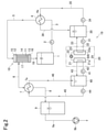
- FIG. 2 shows an example of a distillation apparatus configured to heat the liquid to be distilled using a heat exchanger.
- the raw material water (liquid to be distilled) introduced into the water supply tank 1 via the supply line (not shown) is sent from the water supply tank 1 to the heat exchanger 4 via the pump 2 and the pipe 3. After being heated by the heat exchanger 4, water is sent to the membrane module 10 via the pipe 5.
- the membrane module 10 is a hollow fiber membrane module.
- a large number of hollow fibers 11 are aligned to form a hollow fiber bundle, which is arranged in the vertical direction.
- the upper end side and the lower end side of the hollow fiber bundle are bound by the potting materials 12 and 13.
- the hollow fiber bundle is arranged in the casing 14 of the membrane module 10, the inflow chamber 15 is formed on the upper side of the upper potting material 12, and the outflow chamber 16 is formed on the lower side of the lower potting material 13.
- the inside of each hollow fiber 11 communicates with the inflow chamber 15 and the outflow chamber 16, respectively.
- the liquid to be treated from the pipe 5 flows from the inflow chamber 15 into each hollow fiber 11 (primary side), passes through the hollow fiber 11, flows to the outflow chamber 16, and flows from the outflow chamber 16 to the water supply tank via the pipe 18. Return to 1.
- the secondary side 17 is outside the hollow fiber 11 in the casing 14 and between the potting materials 12 and 13.
- the secondary side 17 communicates with the decompression device 9b via a pipe (steam pipe) 6, a flow path on the cooled side of the heat exchanger (cooler) 7, a pipe 8, a condensed water tank 9, and a pipe 9a.
- the secondary side 17 is decompressed by the decompression device 9b.
- the water in the liquid to be treated permeates the hollow yarn 11 and becomes vapor, which is sucked and discharged from the secondary side 17 to the pipe 6 and discharged to the heat exchanger 7. Cooled with to produce condensed water.
- the condensed water is stored in the condensed water tank 9.
- the condensed water collected in the condensed water tank 9 is taken out from the lower part of the condensed water tank 9 via an extraction line (not shown).
- the upper part of the condensed water tank 9 is connected to the decompression device 9b via the pipe 9a.
- High-temperature water from the heat pump system 19 is passed through the heat source fluid flow path 4a of the heat exchanger 4, and low-temperature water from the heat pump system 19 is passed through the heat source fluid flow path 7a of the heat exchanger 7.
- the heat pump 20 of the heat pump system 19 has a well-known configuration, and a heat medium such as an alternative fron from the evaporator 21 is introduced into the condenser 23 as a high temperature by adiabatic compression by the compressor 22, and the heat medium from the condenser 23 is introduced. Is introduced into the evaporator 21 via the expansion valve 24, and is configured to adiabatically expand and lower the temperature.
- the water in the hot water tank 30 is passed through the heat transfer tube 23a provided in the condenser 23 via the pump 31 and the pipe 32, and is heated by exchanging heat with the high temperature heat medium.
- the water that has been heated to become high temperature water is returned to the hot water tank 30 via the pipe 33.
- the high-temperature water in the hot water tank 30 is passed through the heat source fluid flow path 4a of the heat exchanger 4 via the pump 34 and the pipe 35, and heats and exchanges with the raw material water to heat it.
- the water whose temperature has dropped due to heat exchange with the raw material water is returned to the hot water tank 30 via the pipe 36.
- the water in the cold water tank 40 is passed through the heat transfer tube 21a provided in the evaporator 21 via the pump 41 and the pipe 42, and is cooled by exchanging heat with the low temperature heat medium.
- the water that has been cooled to become low temperature water is returned to the cold water tank 40 via the pipe 43.
- the low-temperature water in the tank 40 is passed through the heat source fluid flow path 7a of the heat exchanger 7 via the pump 44 and the pipe 45, and exchanges heat with steam to cool it.
- the water whose temperature has risen due to heat exchange with steam is returned to the cold water tank 40 via the pipe 46.
- the heat exchanger 7 When the water to be distilled (raw material water) is an aqueous solution of a volatile acid gas such as hydrochloric acid or hydrofluoric acid, and the volatile acid gas is permeated through a membrane module and recovered, the heat exchanger 7 has a high concentration. It will come into contact with corrosive acids. Therefore, a heat exchanger 7 made of a synthetic resin (for example, a fluororesin) having excellent corrosion resistance is used. However, since the synthetic resin has low thermal conductivity, the heat exchanger 7 has a large heat exchange area. It was necessary to use a large heat exchanger. In addition, heat exchangers made of synthetic resin are also expensive.
- a synthetic resin for example, a fluororesin
- An object of the present invention is to provide a distillation apparatus capable of using a metal heat exchanger having high thermal conductivity as a heat exchanger even when the raw material water contains a volatile acidic gas.
- the present invention has the following gist.
- a distillation apparatus having a path for sending water to the working fluid inflow portion of the ejector or the ejector, and a heat exchanger for cooling provided in the path.
- the distillation apparatus of [1] provided with a discharge means for discharging water.
- the distiller is a distillation apparatus according to any one of [1] to [5], which is a membrane-type distiller.
- the steam generated in the distiller is sucked by an ejector or an ejector. Since the steam dissolves in the effluent of the aspirator or ejector, the acid concentration in the effluent is low even when the vapor contains an acidic gas. Therefore, even if the heat exchanger provided in the path for sending the effluent from the tank to the ejector or the ejector as a working fluid is made of metal, it is prevented from corroding for a long period of time. This metal heat exchanger has good heat exchange characteristics and is significantly smaller than the synthetic resin heat exchanger.
- the raw material water (liquid to be distilled) introduced into the water supply tank 1 via the supply line 1F is sent from the water supply tank 1 to the heat exchanger 4 via the pump 2 and the pipe 3, and the heat exchange is performed. After being heated by the vessel 4, water is sent to the membrane module 10 via the pipe 5.
- the membrane module 10 is a hollow fiber membrane module.
- a large number of hollow fibers 11 are aligned to form a hollow fiber bundle, which is arranged in the vertical direction.
- the upper end side and the lower end side of the hollow fiber bundle are bound by the potting materials 12 and 13.
- the hollow fiber bundle is arranged in the casing 14 of the membrane module 10, the inflow chamber 15 is formed on the upper side of the upper potting material 12, and the outflow chamber 16 is formed on the lower side of the lower potting material 13.
- the inside of each hollow fiber 11 communicates with the inflow chamber 15 and the outflow chamber 16, respectively.
- the liquid to be treated from the pipe 5 flows from the inflow chamber 15 into each hollow fiber 11 (primary side), passes through the hollow fiber 11, flows to the outflow chamber 16, and flows from the outflow chamber 16 to the water supply tank via the pipe 18. Return to 1.
- the secondary side 17 is outside the hollow fiber 11 in the casing 14 and between the potting materials 12 and 13.
- the secondary side 17 communicates with the suction portion 50a of the aspirator 50 via a pipe (steam pipe) 6, and the secondary side 17 is depressurized by the aspirator 50.
- the water in the liquid to be treated permeates the hollow fiber 11 and becomes vapor, which is sucked and discharged from the secondary side 17 to the aspirator 50 via the pipe 6. , An absorbent liquid that absorbs vapor is generated.
- the absorption liquid in the absorption liquid tank 90 is introduced into the working fluid inflow port 50b of the aspirator 50 via the pump 51, the pipe 52, the cooled fluid flow path 71 of the highly corrosion-resistant metal heat exchanger 70, and the pipe 54.
- the outflow water from the outlet 50c of the aspirator 50 returns to the absorbent tank 90 via the pipe 55.
- a pipe 57 is branched from the pipe 52, and a valve 58 is provided in the pipe 57.
- An electric conductivity meter 59 is provided in the absorbent liquid tank 90.
- High-temperature water from the hot water tank 30 of the heat pump system 19 is circulated and passed through the heat source fluid flow path 4a of the heat exchanger 4 via the pipes 35 and 36.
- Low-temperature water from the cold water tank 40 of the heat pump system 19 is circulated and passed through the heat source fluid flow path 72 of the heat exchanger 70 via the pipes 45 and 46.
- the heat pump 20 of the heat pump system 19 introduces a heat medium such as an alternative fron from the evaporator 21 into the condenser 23 as a high temperature by adiabatic compression by the compressor 22, and the heat medium from the condenser 23 is introduced to the condenser 23 via the expansion valve 24. It is configured to be introduced into the evaporator 21 and adiabatically expanded to lower the temperature.
- a heat medium such as an alternative fron from the evaporator 21 into the condenser 23 as a high temperature by adiabatic compression by the compressor 22, and the heat medium from the condenser 23 is introduced to the condenser 23 via the expansion valve 24. It is configured to be introduced into the evaporator 21 and adiabatically expanded to lower the temperature.
- the water in the hot water tank 30 is passed through the heat transfer tube 23a provided in the condenser 23 via the pump 31 and the pipe 32, and is heated by exchanging heat with the high temperature heat medium.
- the water that has been heated to become high temperature water is returned to the hot water tank 30 via the pipe 33.
- the high-temperature water in the hot water tank 30 is passed through the heat source fluid flow path 4a of the heat exchanger 4 via the pump 34 and the pipe 35, and heats and exchanges with the raw material water to heat it.
- the water whose temperature has dropped due to heat exchange with the raw material water is returned to the hot water tank 30 via the pipe 36.
- the water in the cold water tank 40 is passed through the heat transfer tube 21a provided in the evaporator 21 via the pump 41 and the pipe 42, and is cooled by exchanging heat with the low temperature heat medium.
- the water that has been cooled to become low temperature water is returned to the cold water tank 40 via the pipe 43.
- the low-temperature water in the tank 40 is passed through the heat source fluid flow path 72 of the heat exchanger 70 via the pump 44 and the pipe 45, and exchanges heat with the absorbing liquid flowing through the fluid to be cooled flow path 71 to cool it. do.
- the water whose temperature has risen due to heat exchange with the absorbing liquid is returned to the cold water tank 40 via the pipe 46.
- make-up water can be introduced into the absorption liquid tank 90 via the make-up water line 56.
- a predetermined amount of water is supplied from the make-up water line 56 to the absorption liquid tank 90 and stored.
- the end of the pipe 6 for sucking the secondary side 17 of the membrane module 10 is connected to the suction portion 50a of the aspirator 50.
- the absorbent liquid in the absorbent liquid tank 90 is circulated and passed through the pump 51, the pipe 52, the metal heat exchanger 70, and the pipes 54 and 55 to the aspirator 50.
- the negative pressure generated by operating the pump 51 and passing water through the aspirator 50 causes the secondary side of the membrane module 10 to flow. Acid gas is sucked from 17 to the pipe 6. This acid gas dissolves in the water flowing in the aspirator 50 and flows into the absorption liquid tank 90 as an acidic aqueous solution. Therefore, when the operation is continued, the acid concentration of the aqueous solution in the absorbent liquid tank 90 gradually increases.
- a volatile acidic gas such as hydrochloric acid or hydrofluoric acid
- the valve 58 is opened and a part of the absorbent liquid is discharged from the pipe 57 to the outside of the system. Instead, make-up water is supplied from the make-up water line 56 to the absorbent tank 90.
- a heat exchanger 70 made of a highly corrosion-resistant metal is used. There is.
- the valve 58 is opened to discharge the high-concentration acid aqueous solution from the pipe 57 to the outside of the system, and the liquid is replenished from the make-up water line 56 instead. Water is introduced into the absorbent tank 90.
- the heat exchanger 70 can be operated stably without being corroded for a long period of time.
- a highly corrosion-resistant metal or alloy such as titanium, titanium alloy or Hastelloy is suitable.
- Titanium 21.9w / (m ⁇ k)
- Hastelloy C 11.1w / (m ⁇ k)
- Polytetrafluoroethylene 0.24w / (m ⁇ k)
- an ejector is used in FIG. 1, an ejector may be used.
- the above embodiment is an example of the present invention, and the present invention may be a form other than the above.
- an electric conductivity meter is used in the above embodiment, various sensors capable of detecting an acid concentration in water such as a resistivity meter and a pH meter can be used.
- the electric conductivity meter is provided in the absorbing liquid tank 90 in the above embodiment, it may be installed in other parts such as pipes 52 and 54.
- a membrane distiller having a membrane module 10 and a water supply tank 1 is installed, but a distiller other than this may be used.
Landscapes
- Chemical & Material Sciences (AREA)
- Chemical Kinetics & Catalysis (AREA)
- Separation Using Semi-Permeable Membranes (AREA)
- Vaporization, Distillation, Condensation, Sublimation, And Cold Traps (AREA)
Abstract
原料水が揮発性酸性ガスを含む場合であっても、熱交換器として熱伝導度の高い金属製熱交換器を用いることができる蒸留装置が提供される。原料水は、給水タンク1からポンプ2及び配管3を介して熱交換器4に送液され、該熱交換器4で加熱された後、膜モジュール10に送水され、膜蒸留処理される。膜モジュール10の2次側で生じた蒸気はアスピレータ50で吸引される。アスピレータ50へは吸収液タンク90内の吸収液がポンプ51、冷却用熱交換器70を経て供給される。熱交換器70はチタン等の金属製である。
Description
本発明は、蒸留装置に係り、特に蒸留処理される液を熱交換器を用いて加熱するよう構成された蒸留装置に関する。本発明は、特に揮発性酸性ガスの水溶液から揮発性酸性ガスを分離する用途に用いるのに好適な蒸留装置に関する。
蒸留処理される液を熱交換器を用いて加熱するよう構成された蒸留装置の一例を図2に示す。
供給ライン(図示略)を介して給水タンク1内に導入された原料水(蒸留処理される液)は、該給水タンク1からポンプ2及び配管3を介して熱交換器4に送液され、該熱交換器4で加熱された後、配管5を介して膜モジュール10に送水される。
この従来例では、膜モジュール10は中空糸膜モジュールである。膜モジュール10では、多数本の中空糸11が引き揃えられて中空糸束とされ、上下方向に配設されている。中空糸束の上端側及び下端側がポッティング材12,13で結束されている。
中空糸束は膜モジュール10のケーシング14内に配置されており、上側ポッティング材12の上側に流入室15が形成され、下側ポッティング材13の下側に流出室16が形成されている。各中空糸11内はそれぞれ流入室15及び流出室16内に連通している。
配管5からの被処理液は、流入室15から各中空糸11内(一次側)に流入し、中空糸11を通り、流出室16へ流れ、該流出室16から配管18を介して給水タンク1に戻る。
ケーシング14内における中空糸11外であって且つポッティング材12,13間が二次側17である。
該二次側17は、配管(蒸気配管)6、熱交換器(冷却器)7の被冷却側流路、配管8、凝縮水タンク9及び配管9aを介して減圧装置9bに連通しており、該減圧装置9bによって該二次側17が減圧される。
被処理液が中空糸17内(一次側)を流れる間に被処理液中の水が中空糸11を透過し、蒸気となって二次側17から配管6へ吸引排出され、熱交換器7で冷却されて凝縮水が生成する。凝縮水は、凝縮水タンク9に貯留される。凝縮水タンク9内に溜まった凝縮水は、該凝縮水タンク9の下部から取出ライン(図示略)を介して取り出される。凝縮水タンク9の上部が配管9aを介して減圧装置9bに接続されている。
熱交換器4の熱源流体流路4aには、ヒートポンプシステム19からの高温水が通水され、熱交換器7の熱源流体流路7aにはヒートポンプシステム19からの低温水が通水される。
ヒートポンプシステム19のヒートポンプ20は、周知構成のものであり、蒸発器21からの代替フロン等の熱媒体を圧縮機22で断熱圧縮により高温として凝縮器23に導入し、凝縮器23からの熱媒体を膨張弁24を介して蒸発器21に導入し、断熱膨張させて降温させるように構成されている。
凝縮器23内に設けられた伝熱チューブ23aに温水タンク30内の水がポンプ31及び配管32を介して通水され、高温熱媒体と熱交換して加熱される。加熱されて高温水となった水は、配管33を介して温水タンク30に返送される。
この温水タンク30内の高温水が、ポンプ34及び配管35を介して熱交換器4の熱源流体流路4aに通水され、原料水と熱交換してこれを加熱する。原料水と熱交換することにより温度が低下した水は、配管36を介して温水タンク30に返送される。
蒸発器21内に設けられた伝熱チューブ21aに、冷水タンク40内の水がポンプ41及び配管42を介して通水され、低温熱媒体と熱交換して冷却される。冷却されて低温水となった水は、配管43を介して冷水タンク40に返送される。
このタンク40内の低温水が、ポンプ44及び配管45を介して熱交換器7の熱源流体流路7aに通水され、蒸気と熱交換してこれを冷却する。蒸気と熱交換することにより温度が上昇した水は、配管46を介して冷水タンク40に返送される。
蒸留処理される水(原料水)が塩酸、フッ酸などの揮発性酸性ガスの水溶液であり、該揮発性酸性ガスを膜モジュールで膜透過させて回収する場合、熱交換器7は高濃度の腐食性酸と接することになる。そのため、熱交換器7として耐腐食性に優れた合成樹脂(例えばフッ素樹脂)製のものが用いられているが、合成樹脂は熱伝導度が低いので、熱交換器7として熱交換面積の大きい大型熱交換器を用いる必要があった。また、合成樹脂製の熱交換器はコスト高でもある。
本発明は、原料水が揮発性酸性ガスを含む場合であっても、熱交換器として熱伝導度の高い金属製熱交換器を用いることができる蒸留装置を提供することを課題とする。
本発明は、次を要旨とするものである。
[1] 蒸留処理される液が導入される蒸留器と、該蒸留器内で生じた蒸気を吸引するアスピレータ又はエゼクタと、該アスピレータ又はエゼクタの流出水が流入するタンクと、該タンク内の水を前記アスピレータ又はエゼクタの作動流体流入部に送水する経路と、該経路に設けられた冷却用の熱交換器とを有する蒸留装置。
[2] 前記タンク内の水、又はタンクとアスピレータもしくはエゼクタとの間を循環する水の水質測定手段と、該水質測定手段で測定された水質が規定値を超えた場合に該水の一部を排出する排出手段を備えた[1]の蒸留装置。
[3] 前記水は酸の水溶液であり、前記水質は電気伝導度又は比抵抗である[2]の蒸留装置。
[4] 前記熱交換器は高耐食性金属製である[1]~[3]のいずれかの蒸留装置。
[5] 前記高耐食性金属は、チタン、チタン合金又はハステロイである[4]の蒸留装置。
[6] 前記蒸留器は、膜式蒸留器である[1]~[5]のいずれかの蒸留装置。
[7] 前記タンクに水を補給する手段を有する[1]~[6]のいずれかの蒸留装置。
本発明の蒸留装置では、蒸留器内で生じた蒸気をアスピレータ又はエゼクタで吸引する。このアスピレータ又はエゼクタの流出水中に蒸気が溶解するため、蒸気が酸性ガスを含む場合であっても、該流出水中の酸濃度は低いものとなる。そのため、この流出水をタンクからアスピレータ又はエゼクタに作動流体として送水する経路に設けられた熱交換器を金属製のものとしても、長期にわたって腐食することが防止される。この金属製の熱交換器は、熱交換特性が良好であり、合成樹脂製の熱交換器に比べて著しく小型である。
本発明の一態様では、作動流体としての水の酸濃度が所定値よりも高くなったときには、該水の一部を排出し、新しい水を追加する。
以下、図1を参照して実施の形態について説明する。
供給ライン1Fを介して給水タンク1内に導入された原料水(蒸留処理される液)は、該給水タンク1からポンプ2及び配管3を介して熱交換器4に送液され、該熱交換器4で加熱された後、配管5を介して膜モジュール10に送水される。
膜モジュール10は中空糸膜モジュールである。膜モジュール10では、多数本の中空糸11が引き揃えられて中空糸束とされ、上下方向に配設されている。中空糸束の上端側及び下端側がポッティング材12,13で結束されている。
中空糸束は膜モジュール10のケーシング14内に配置されており、上側ポッティング材12の上側に流入室15が形成され、下側ポッティング材13の下側に流出室16が形成されている。各中空糸11内はそれぞれ流入室15及び流出室16内に連通している。
配管5からの被処理液は、流入室15から各中空糸11内(一次側)に流入し、中空糸11を通り、流出室16へ流れ、該流出室16から配管18を介して給水タンク1に戻る。
ケーシング14内における中空糸11外であって且つポッティング材12,13間が二次側17である。
該二次側17は、配管(蒸気配管)6を介してアスピレータ50の吸引部50aに連通しており、該アスピレータ50によって該二次側17が減圧される。
被処理液が中空糸17内(一次側)を流れる間に被処理液中の水が中空糸11を透過し、蒸気となって二次側17から配管6を介してアスピレータ50に吸引排出され、蒸気を吸収した吸収液が生成する。
アスピレータ50の作動流体流入口50bへは吸収液タンク90内の吸収液が、ポンプ51、配管52、高耐食性金属製熱交換器70の被冷却流体流路71、及び配管54を介して導入される。アスピレータ50の流出口50cからの流出水は配管55を介して吸収液タンク90に戻る。
配管52からは配管57が分岐しており、該配管57に弁58が設けられている。吸収液タンク90に電気伝導度計59が設けられている。
熱交換器4の熱源流体流路4aには、ヒートポンプシステム19の温水タンク30からの高温水が配管35,36を介して循環通水される。熱交換器70の熱源流体流路72にはヒートポンプシステム19の冷水タンク40からの低温水が配管45,46を介して循環通水される。
ヒートポンプシステム19のヒートポンプ20は、蒸発器21からの代替フロン等の熱媒体を圧縮機22で断熱圧縮により高温として凝縮器23に導入し、凝縮器23からの熱媒体を膨張弁24を介して蒸発器21に導入し、断熱膨張させて降温させるように構成されている。
凝縮器23内に設けられた伝熱チューブ23aに温水タンク30内の水がポンプ31及び配管32を介して通水され、高温熱媒体と熱交換して加熱される。加熱されて高温水となった水は、配管33を介して温水タンク30に返送される。
この温水タンク30内の高温水が、ポンプ34及び配管35を介して熱交換器4の熱源流体流路4aに通水され、原料水と熱交換してこれを加熱する。原料水と熱交換することにより温度が低下した水は、配管36を介して温水タンク30に返送される。
蒸発器21内に設けられた伝熱チューブ21aに、冷水タンク40内の水がポンプ41及び配管42を介して通水され、低温熱媒体と熱交換して冷却される。冷却されて低温水となった水は、配管43を介して冷水タンク40に返送される。
このタンク40内の低温水が、ポンプ44及び配管45を介して熱交換器70の熱源流体流路72に通水され、被冷却流体流路71を流れる吸収液と熱交換してこれを冷却する。吸収液と熱交換することにより温度が上昇した水は、配管46を介して冷水タンク40に返送される。
吸収液タンク90へは補給水ライン56を介して補給水が導入可能とされている。蒸留装置の運転開始に先立って、補給水ライン56から吸収液タンク90に所定量の水を供給して貯めておく。
前述の通り、膜モジュール10の2次側17を吸引するための配管6の末端がアスピレータ50の吸引部50aに接続されている。アスピレータ50へは吸収液タンク90内の吸収液が、ポンプ51、配管52、金属製熱交換器70及び配管54、55を介して循環通水される。
給水タンク1内の水が塩酸、フッ酸などの揮発性酸性ガスの水溶液である場合、ポンプ51を作動させてアスピレータ50に通水することにより生じた負圧によって、膜モジュール10の2次側17から配管6へ酸性ガスが吸引される。この酸性ガスは、アスピレータ50内を流れる水に溶け込み、酸性水溶液として吸収液タンク90に流入する。そのため、運転を継続すると、吸収液タンク90内の水溶液の酸濃度が次第に高くなる。
吸収液タンク90に設けられた電気伝導度計59で検出される電気伝導度が所定値よりも高くなったときには、弁58が開とされ、吸収液の一部が配管57から系外に排出され、代りに補給水が補給水ライン56から吸収液タンク90へ供給される。
この実施の形態では、上記の通り、熱交換器70の被冷却流体流路71には、吸収液タンク90内の酸性水溶液が流れるので、熱交換器70として高耐食性金属製のものを用いている。また、吸収液タンク90内の液の電気伝導度が所定値よりも高くなったときには、弁58を開として高濃度酸水溶液を配管57から系外に排出し、代りに補給水ライン56から補給水を吸収液タンク90に導入する。これにより、熱交換器70が長期にわたって腐食することなく、安定した運転を行うことができる。
熱交換器70を構成するための高耐食性金属としては、チタン、チタン合金やハステロイなどの高耐食性金属又は合金が好適である。
なお、チタン、ハステロイC及びポリテトラフルオロエチレンの熱伝導率の一例を次に示す。
チタン:21.9w/(m・k)
ハステロイC:11.1w/(m・k)
ポリテトラフルオロエチレン:0.24w/(m・k)
チタン:21.9w/(m・k)
ハステロイC:11.1w/(m・k)
ポリテトラフルオロエチレン:0.24w/(m・k)
このように、チタンやハステロイの熱伝導率はポリテトラフルオロエチレンに比べて著しく高いので、熱交換器70として熱交換面積の小さい、小型のものを用いることが可能となる。
なお、図1ではアスピレータが用いられているが、エゼクタを用いてもよい。
上記実施の形態は本発明の一例であり、本発明は上記以外の形態とされてもよい。例えば、上記実施の形態では電気伝導度計が用いられているが、比抵抗計、pH計など水中の酸濃度を検出できる各種センサを用いることができる。
また、上記実施の形態では電気伝導度計は吸収液タンク90に設けられているが、配管52,54など他の部位に設置されてもよい。
上記実施の形態では膜モジュール10と給水タンク1とを有した膜式蒸留器が設置されているが、これ以外の蒸留器を用いてもよい。
本発明を特定の態様を用いて詳細に説明したが、本発明の意図と範囲を離れることなく様々な変更が可能であることは当業者に明らかである。
本出願は、2020年9月18日付で出願された日本特許出願2020-157300に基づいており、その全体が引用により援用される。
本出願は、2020年9月18日付で出願された日本特許出願2020-157300に基づいており、その全体が引用により援用される。
1 給水タンク
4,7、70 熱交換器
9 凝縮水タンク
19 ヒートポンプシステム
20 ヒートポンプ
21 蒸発器
22 圧縮機
23 凝縮器
24 膨張弁
30 温水タンク
40 冷水タンク
50 アスピレータ
59 電気伝導度計
90 吸収液タンク
4,7、70 熱交換器
9 凝縮水タンク
19 ヒートポンプシステム
20 ヒートポンプ
21 蒸発器
22 圧縮機
23 凝縮器
24 膨張弁
30 温水タンク
40 冷水タンク
50 アスピレータ
59 電気伝導度計
90 吸収液タンク
Claims (7)
- 蒸留処理される液が導入される蒸留器と、
該蒸留器内で生じた蒸気を吸引するアスピレータ又はエゼクタと、
該アスピレータ又はエゼクタの流出水が流入するタンクと、
該タンク内の水を前記アスピレータ又はエゼクタの作動流体流入部に送水する経路と、
該経路に設けられた冷却用の熱交換器と
を有する蒸留装置。 - 前記タンク内の水、又はタンクとアスピレータもしくはエゼクタとの間を循環する水の水質測定手段と、該水質測定手段で測定された水質が規定値を超えた場合に該水の一部を排出する排出手段を備えた請求項1の蒸留装置。
- 前記水は酸の水溶液であり、前記水質は電気伝導度又は比抵抗である請求項2の蒸留装置。
- 前記熱交換器は高耐食性金属製である請求項1~3のいずれかの蒸留装置。
- 前記高耐食性金属はチタン、チタン合金又はハステロイである請求項4の蒸留装置。
- 前記蒸留器は、膜式蒸留器である請求項1~5のいずれかの蒸留装置。
- 前記タンクに水を補給する手段を有する請求項1~6のいずれかの蒸留装置。
Priority Applications (1)
| Application Number | Priority Date | Filing Date | Title |
|---|---|---|---|
| CN202180062548.7A CN116113487A (zh) | 2020-09-18 | 2021-09-06 | 蒸馏装置 |
Applications Claiming Priority (2)
| Application Number | Priority Date | Filing Date | Title |
|---|---|---|---|
| JP2020157300A JP7120283B2 (ja) | 2020-09-18 | 2020-09-18 | 蒸留装置 |
| JP2020-157300 | 2020-09-18 |
Publications (1)
| Publication Number | Publication Date |
|---|---|
| WO2022059535A1 true WO2022059535A1 (ja) | 2022-03-24 |
Family
ID=80776907
Family Applications (1)
| Application Number | Title | Priority Date | Filing Date |
|---|---|---|---|
| PCT/JP2021/032605 Ceased WO2022059535A1 (ja) | 2020-09-18 | 2021-09-06 | 蒸留装置 |
Country Status (4)
| Country | Link |
|---|---|
| JP (1) | JP7120283B2 (ja) |
| CN (1) | CN116113487A (ja) |
| TW (1) | TWI888642B (ja) |
| WO (1) | WO2022059535A1 (ja) |
Citations (4)
| Publication number | Priority date | Publication date | Assignee | Title |
|---|---|---|---|---|
| JPH0352627A (ja) * | 1989-07-19 | 1991-03-06 | Hitachi Ltd | 膜蒸留装置 |
| JPH05115857A (ja) * | 1991-10-28 | 1993-05-14 | Toshiba Corp | 洗浄排水処理方法および洗浄装置 |
| EP0634198A1 (en) * | 1993-07-08 | 1995-01-18 | Agfa-Gevaert N.V. | Installation for controlling the underpressure in an evaporator apparatus |
| JP2002327288A (ja) * | 2001-04-27 | 2002-11-15 | Nittetsu Mining Co Ltd | 塩化銅液から塩酸と銅を回収する方法 |
Family Cites Families (4)
| Publication number | Priority date | Publication date | Assignee | Title |
|---|---|---|---|---|
| CN86203155U (zh) * | 1986-05-10 | 1987-05-27 | 大连工学院 | 喷射热泵式蒸馏水器 |
| JP3394815B2 (ja) * | 1993-08-30 | 2003-04-07 | 東静電気株式会社 | 減圧蒸留方法および減圧蒸留装置 |
| CN201634418U (zh) * | 2010-03-16 | 2010-11-17 | 杭州电子科技大学 | 一种酸性蚀刻液的处理装置 |
| CN208541989U (zh) * | 2018-05-28 | 2019-02-26 | 湖北三宁化工股份有限公司 | 尿素尾气回收利用的装置 |
-
2020
- 2020-09-18 JP JP2020157300A patent/JP7120283B2/ja active Active
-
2021
- 2021-09-06 CN CN202180062548.7A patent/CN116113487A/zh active Pending
- 2021-09-06 WO PCT/JP2021/032605 patent/WO2022059535A1/ja not_active Ceased
- 2021-09-11 TW TW110133928A patent/TWI888642B/zh active
Patent Citations (4)
| Publication number | Priority date | Publication date | Assignee | Title |
|---|---|---|---|---|
| JPH0352627A (ja) * | 1989-07-19 | 1991-03-06 | Hitachi Ltd | 膜蒸留装置 |
| JPH05115857A (ja) * | 1991-10-28 | 1993-05-14 | Toshiba Corp | 洗浄排水処理方法および洗浄装置 |
| EP0634198A1 (en) * | 1993-07-08 | 1995-01-18 | Agfa-Gevaert N.V. | Installation for controlling the underpressure in an evaporator apparatus |
| JP2002327288A (ja) * | 2001-04-27 | 2002-11-15 | Nittetsu Mining Co Ltd | 塩化銅液から塩酸と銅を回収する方法 |
Also Published As
| Publication number | Publication date |
|---|---|
| TWI888642B (zh) | 2025-07-01 |
| JP2022051045A (ja) | 2022-03-31 |
| JP7120283B2 (ja) | 2022-08-17 |
| CN116113487A (zh) | 2023-05-12 |
| TW202212747A (zh) | 2022-04-01 |
Similar Documents
| Publication | Publication Date | Title |
|---|---|---|
| CN111540496B (zh) | 一种非接触式高效膜蒸馏处理放射性废水的系统及方法 | |
| US4776181A (en) | Evaporative heat exchanger | |
| WO2011135724A1 (ja) | 純粋液体製造装置 | |
| RU2631182C2 (ru) | Процесс предварительного нагревания свежей воды в паротурбинных электростанциях с отводом технологического пара | |
| WO2022059535A1 (ja) | 蒸留装置 | |
| CN201093905Y (zh) | 一种无机热管喷淋式蒸发器 | |
| CN204594266U (zh) | 一种可测温冷凝装置 | |
| CN102107922A (zh) | 一种处理工业废水的工艺及其装置 | |
| CN204778912U (zh) | 一种蒸发式液体浓缩处理系统 | |
| CN210015067U (zh) | 一种降膜蒸发器传热性能测试系统 | |
| CN119660986B (zh) | 一种连续分盐式高浓盐水换热工艺 | |
| CN224109076U (zh) | 蒸发器性能测试实验平台 | |
| JP6958687B1 (ja) | 膜蒸留装置及びその運転方法 | |
| CN113175808A (zh) | 一种换热管干燥系统及方法 | |
| RU2626614C2 (ru) | Узел подачи пара в теплообменный аппарат | |
| Park | A study on thermal performance of plate cooler for cooling medium speed engine lubricant oil | |
| Lara Ruiz | An advanced vapor-compression desalination system | |
| JP5389704B2 (ja) | 熱交換器 | |
| CN210332293U (zh) | 一种隔效顺流膜外传热的多效膜蒸馏装置 | |
| CA1267540A (en) | Evaporative heat exchanger | |
| SU1084579A1 (ru) | Способ исследовани теплообмена на наружной поверхности труб парового конденсатора | |
| CN116147386A (zh) | 非金属换热材料的板式降膜换热组件、mvr蒸发装置及制备方法 | |
| CN118794008A (zh) | 一种过热蒸汽热泵系统 | |
| US336233A (en) | Machine for the manufacture of ice and for refrigerating purposes | |
| WO2025017109A1 (en) | Water distillation system for hvac&r system |
Legal Events
| Date | Code | Title | Description |
|---|---|---|---|
| 121 | Ep: the epo has been informed by wipo that ep was designated in this application |
Ref document number: 21869222 Country of ref document: EP Kind code of ref document: A1 |
|
| NENP | Non-entry into the national phase |
Ref country code: DE |
|
| 122 | Ep: pct application non-entry in european phase |
Ref document number: 21869222 Country of ref document: EP Kind code of ref document: A1 |