WO2022059093A1 - 監視システム、方法、及びプログラムが格納された非一時的なコンピュータ可読媒体 - Google Patents
監視システム、方法、及びプログラムが格納された非一時的なコンピュータ可読媒体 Download PDFInfo
- Publication number
- WO2022059093A1 WO2022059093A1 PCT/JP2020/035087 JP2020035087W WO2022059093A1 WO 2022059093 A1 WO2022059093 A1 WO 2022059093A1 JP 2020035087 W JP2020035087 W JP 2020035087W WO 2022059093 A1 WO2022059093 A1 WO 2022059093A1
- Authority
- WO
- WIPO (PCT)
- Prior art keywords
- dimensional
- point cloud
- cloud data
- monitoring
- invalid
- Prior art date
- Legal status (The legal status is an assumption and is not a legal conclusion. Google has not performed a legal analysis and makes no representation as to the accuracy of the status listed.)
- Ceased
Links
Images


Classifications
-
- G—PHYSICS
- G01—MEASURING; TESTING
- G01S—RADIO DIRECTION-FINDING; RADIO NAVIGATION; DETERMINING DISTANCE OR VELOCITY BY USE OF RADIO WAVES; LOCATING OR PRESENCE-DETECTING BY USE OF THE REFLECTION OR RERADIATION OF RADIO WAVES; ANALOGOUS ARRANGEMENTS USING OTHER WAVES
- G01S7/00—Details of systems according to groups G01S13/00, G01S15/00, G01S17/00
- G01S7/48—Details of systems according to groups G01S13/00, G01S15/00, G01S17/00 of systems according to group G01S17/00
- G01S7/497—Means for monitoring or calibrating
-
- G—PHYSICS
- G01—MEASURING; TESTING
- G01S—RADIO DIRECTION-FINDING; RADIO NAVIGATION; DETERMINING DISTANCE OR VELOCITY BY USE OF RADIO WAVES; LOCATING OR PRESENCE-DETECTING BY USE OF THE REFLECTION OR RERADIATION OF RADIO WAVES; ANALOGOUS ARRANGEMENTS USING OTHER WAVES
- G01S17/00—Systems using the reflection or reradiation of electromagnetic waves other than radio waves, e.g. lidar systems
- G01S17/66—Tracking systems using electromagnetic waves other than radio waves
-
- G—PHYSICS
- G01—MEASURING; TESTING
- G01B—MEASURING LENGTH, THICKNESS OR SIMILAR LINEAR DIMENSIONS; MEASURING ANGLES; MEASURING AREAS; MEASURING IRREGULARITIES OF SURFACES OR CONTOURS
- G01B11/00—Measuring arrangements characterised by the use of optical techniques
-
- G—PHYSICS
- G01—MEASURING; TESTING
- G01S—RADIO DIRECTION-FINDING; RADIO NAVIGATION; DETERMINING DISTANCE OR VELOCITY BY USE OF RADIO WAVES; LOCATING OR PRESENCE-DETECTING BY USE OF THE REFLECTION OR RERADIATION OF RADIO WAVES; ANALOGOUS ARRANGEMENTS USING OTHER WAVES
- G01S17/00—Systems using the reflection or reradiation of electromagnetic waves other than radio waves, e.g. lidar systems
- G01S17/88—Lidar systems specially adapted for specific applications
- G01S17/89—Lidar systems specially adapted for specific applications for mapping or imaging
Definitions
- This disclosure relates to a non-temporary computer-readable medium in which a monitoring system, method, and program for the purpose of suppressing false detection of a monitoring target are stored.
- a visual inspection is conducted by a patrolman in order to identify a failure of the equipment in the facility due to aging.
- a system has been introduced that makes an objective and automatic judgment by using a monitoring device such as a camera.
- a monitoring device such as a camera.
- LiDAR Light Detection And Ringing
- a laser ranging device can identify an abnormal part of the appearance of the facility by capturing the three-dimensional shape of the facility.
- LiDAR irradiates the target with laser light and receives the reflected light from the surface of the target to measure the distance to the irradiation point from the time difference between transmission and reception.
- the three-dimensional shape of the target can be acquired as a data group having three-dimensional coordinate points.
- Patent Document 1 discloses a control device that acquires a camera image in the direction of the sun after specifying the direction of the sun, and limits laser scanning in that direction when the brightness value of the image is equal to or higher than a predetermined value. ..
- Patent Document 1 it is necessary to convey an instruction to exclude the laser scan in a specific direction to the main body of the laser ranging device. Contrary to the above, some laser ranging devices accept commands that set the scan range only in a specific direction, and devices do not accept the designation of the scan range. When operating a monitoring system using such a device, the method disclosed in Patent Document 1 does not function as a system including noise countermeasures for the sun.
- This disclosure is made to solve such problems. That is, it is intended to provide a monitoring system, a monitoring method, and a monitoring program capable of suppressing false detection of a monitoring target in monitoring using point cloud data acquired by a laser ranging device.
- the monitoring system is acquired by a linear calculation means for calculating a straight line connecting the three-dimensional coordinates of the light source and the three-dimensional coordinates of the three-dimensional measuring device for measuring the shape of the measurement target, and the three-dimensional measuring device.
- the measurement target is monitored based on the three-dimensional invalid area determination means for determining the three-dimensional invalid area in which the acquired point group data is invalid based on the straight line, and the acquired point group data and the three-dimensional invalid area. It is provided with a point group data processing means.
- a straight line connecting the three-dimensional coordinates of the light source and the three-dimensional coordinates of the three-dimensional measuring device for measuring the shape of the measurement target is calculated, and the acquisition point group acquired by the three-dimensional measuring device is calculated.
- a three-dimensional invalid region in which data is invalid is determined based on the straight line, and the measurement target is monitored based on the acquisition point group data and the three-dimensional invalid region.
- the monitoring program according to the present disclosure is acquired by the process of calculating a straight line connecting the three-dimensional coordinates of the light source and the three-dimensional coordinates of the three-dimensional measuring device for measuring the shape of the measurement target on the computer, and the three-dimensional measuring device.
- a monitoring system capable of suppressing false detection of a monitoring target in monitoring using point cloud data acquired by a laser ranging device. ..
- FIG. 5 is a block diagram illustrating an operation of instructing remeasurement after removing a point cloud included in a three-dimensional invalid region according to a fifth embodiment.
- FIG. 5 is a block diagram illustrating an operation of instructing remeasurement after removing a point cloud of a monitoring result included in a three-dimensional invalid region according to a fifth embodiment.
- FIG. 5 is a block diagram illustrating an operation of instructing remeasurement after removing a point cloud of a monitoring result included in a three-dimensional invalid region according to a fifth embodiment. It is a figure which illustrates the operation which shows the 3D invalid area on the monitoring screen which concerns on 5th Embodiment. It is a block diagram which illustrates the operation which shows the 3D invalid area on the monitoring screen which concerns on 5th Embodiment.
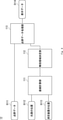
- FIG. 1 is a block diagram showing a functional configuration of the monitoring system 10 according to the first embodiment.
- the monitoring system 10 includes a linear calculation unit 111, an invalid region determination unit 112, and a point cloud data processing unit 113.
- the straight line calculation unit 111 calculates a straight line connecting the three-dimensional coordinates of the light source and the three-dimensional coordinates of the three-dimensional measuring device that measures the shape of the measurement target.
- the three-dimensional measuring device is, for example, LiDAR.
- the invalid area determination unit 112 specifies a three-dimensional invalid area in which the acquired point cloud data acquired by the three-dimensional measuring device is invalid, based on the straight line calculated by the linear calculation unit 111.
- the three-dimensional invalid area is, in other words, an area in which the acquired point cloud data acquired by the three-dimensional measuring device is affected by the noise caused by the light source.
- the point cloud data processing unit 113 monitors the measurement target based on the acquired point cloud data and the three-dimensional invalid area specified by the invalid area determination unit 112.
- the point cloud data processing unit 113 may monitor the measurement target so as not to detect an abnormality in the three-dimensional invalid region. For example, the point cloud data processing unit 113 may detect an abnormality of the measurement target based on the effective point cloud data obtained by removing the data included in the three-dimensional invalid region from the acquired point cloud data. Further, even if the point cloud data processing unit 113 identifies the candidate of the abnormal part based on the acquired point cloud data and then removes the candidate included in the three-dimensional invalid area from the specific result, the abnormal part is specified. good.
- the information regarding the specified abnormal location is also referred to as abnormal information.
- the point cloud data processing unit 113 identifies an abnormal part from the acquired point cloud data, determines whether or not the abnormal part is included in the invalid area, and displays the abnormal part according to the determination result (non-identical part). It may be displayed in the figure). For example, by displaying the abnormal part in the invalid area in a display form different from that of other abnormal parts, the observer can appropriately monitor.
- the point cloud data processing unit 113 performs exceptional processing (exception processing) for the acquired point cloud data based on the three-dimensional invalid area.
- the monitoring system 10 includes a processor, a memory, and a storage device as a configuration (not shown). Further, the storage device stores a computer program in which the processing of the monitoring method according to the present embodiment is implemented. Then, the processor reads the computer program from the storage device into the memory and executes the computer program. As a result, the processor realizes the functions of the linear calculation unit 111, the invalid area determination unit 112, and the point cloud data processing unit 113.
- the linear calculation unit 111, the invalid area determination unit 112, and the point cloud data processing unit 113 may each be realized by dedicated hardware. Further, a part or all of each component of each device may be realized by a general-purpose or dedicated circuitry, a processor, or a combination thereof. These may be composed of a single chip or may be composed of a plurality of chips connected via a bus. A part or all of each component of each device may be realized by the combination of the circuit or the like and the program described above. Further, as a processor, a CPU (Central Processing Unit), a GPU (Graphics Processing Unit), an FPGA (field-programmable gate array), or the like can be used.
- a CPU Central Processing Unit
- GPU Graphics Processing Unit
- FPGA field-programmable gate array
- each component of the monitoring system 10 when a part or all of each component of the monitoring system 10 is realized by a plurality of information processing devices and circuits, the plurality of information processing devices and circuits may be centrally arranged or distributed. It may be arranged.
- the information processing device, the circuit, and the like may be realized as a form in which each is connected via a communication network, such as a client-server system and a cloud computing system.
- the function of the monitoring system 10 may be provided in the SaaS (Software as a Service) format.
- the monitoring system according to the first embodiment identifies the three-dimensional invalid region affected by noise based on the straight line connecting the light source and the three-dimensional measuring device, and monitors the measurement target based on the three-dimensional invalid region. Therefore, the monitoring system according to the first embodiment can suppress erroneous detection of the monitoring target due to noise.
- the monitoring system 10a As shown in FIG. 2, the monitoring system 10a according to the second embodiment includes a measuring device 11, a data processing device 12, and a display device 13.
- the measuring device 11 includes a device for acquiring three-dimensional shape data to be monitored, and outputs point cloud data, which is a set of points having three-dimensional coordinates.
- the reflected luminance and color information of the laser may be added to each point of the point cloud data.
- the data processing device 12 is a device that performs processing on the point cloud data acquired by the measuring device 11 to determine an abnormality to be monitored and to identify a location where an abnormality has occurred.
- the display device 13 is a device that displays information on the abnormality determined by the data processing device 12 in a form that can be visually recognized by the observer. In the following description of the embodiment, the details of the data processing device 12 will be described.
- FIG. 3 is a diagram illustrating an operation of determining a three-dimensional invalid region based on the position of the measuring device and the position of the light source according to the second embodiment of the present invention. It is assumed that the measurement target 100 is a target to be measured by the three-dimensional measuring device 101 included in the measuring device 11, and the light source 102 is present at the time of measurement.
- the three-dimensional measuring device 101 is a device for acquiring three-dimensional shape data including LiDAR.
- the light source 102 is an object that emits high-intensity light including the sun and lighting.
- the group data becomes data mixed with noise by receiving noise light from the light source 102. Therefore, the measurement data in the three-dimensional invalid region 104 is not accurate, and there is a possibility that it is erroneously determined as an abnormality when the monitoring processing means is applied.
- the three-dimensional invalid region 104 has a conical shape with the coordinates of the three-dimensional measuring device 101 as the apex, but it may have a cylindrical shape or an elliptical bottom surface.
- FIG. 4 is a block diagram of a data processing device 12 illustrating an operation of processing point cloud data after determining a three-dimensional invalid region according to a second embodiment of the present invention.
- the point cloud data D111 is the point cloud data output from the measuring device 11.
- the position D112 of the light source and the position D113 of the measuring device are values that specify a three-dimensional space such as a three-dimensional coordinate value, and are designated from the outside.
- the straight line calculation unit 111 calculates a straight line connecting two points, the position D112 of the light source and the position D113 of the measuring device.
- the invalid area determination unit 112 determines a three-dimensional area to be exception-handled as a three-dimensional invalid area based on the straight line calculated by the straight line calculation unit 111.
- the point cloud data processing unit 113 processes the point cloud data D111 with the three-dimensional invalid area output from the invalid area determination unit 112 as the target of exception processing, and outputs the display data D114 to be displayed on the monitoring screen.
- the details of the point cloud data processing unit 113 will be described in the third to sixth embodiments.
- FIG. 5 is a flowchart illustrating the processing of the invalid region determination unit 112 according to the second embodiment of the present invention. It is assumed that each point of the point cloud data D111 is given a value of reflected luminance.
- the straight line D120 is a straight line calculated by the straight line calculation unit 111.
- the invalid area determination unit 112 extracts data corresponding to the periphery of the straight line D120 from the point cloud data D111 (step S120).
- An example is a method in which the circumference of the straight line D120 is defined by a radius about the straight line D120.
- the invalid region determination unit 112 calculates the gradient of the reflected luminance value centered on the straight line D120 with respect to the point cloud extracted in step S130 described later (step S121).
- An example is a method of calculating the gradient of the reflected luminance value radially around the straight line D120 with respect to the point cloud data projected in the direction of the straight line D120. Processing may be performed to reduce the measurement error of the reflected luminance value based on the neighboring points of each point.
- the invalid area determination unit 112 outputs the corresponding area as the three-dimensional invalid area D121.
- the invalid area determination unit 112 sets the corresponding area as the three-dimensional effective area D122.
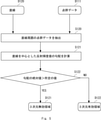
- FIG. 6 is a flowchart illustrating the processing of the invalid region determination unit 112 according to the second embodiment of the present invention.
- the device for measuring the illuminance value D130 is a sensor for measuring the illuminance included in the measuring device 11 and is installed close to the three-dimensional measuring device 101.
- This sensor is a device that measures the brightness of ambient light, and may be an illuminance sensor or a camera that captures an optical image.
- the invalid area determination unit 112 calculates the range of the area to be determined to be invalid based on the illuminance value D130 (step S130).
- this range is determined based on an equation that specifies the radius with respect to the illuminance value, which is determined by referring to a table in which the radius corresponding to the illuminance value is described.
- the radius value may be variable according to the distance from the measuring device 11.
- the invalid area determination unit 112 outputs the range determined by step S130 about the straight line D120 as the three-dimensional invalid area D121 (step S131).
- the monitoring system of the second embodiment can apply exception handling to the measured point cloud data after specifying the three-dimensional region determined to be disturbed by the noise of the light source.
- the method of Patent Document 1 it is possible to configure a monitoring system that processes a point cloud disturbed by a light source such as the sun in a form that does not depend on the operating system of the measuring device.
- FIG. 7 is a diagram illustrating an operation of removing a point cloud included in a three-dimensional invalid region in the point cloud data processing unit 113 according to the second embodiment of the present invention.
- the measurement target point cloud 200 is point cloud data measured by the coordinate measuring device 101. As in FIG. 3, it is assumed that the light source 102 is present at the time of measurement and the three-dimensional invalid region 104 is set according to the second embodiment.
- the measurement target point group 201 is a point group obtained by removing the point group corresponding to the three-dimensional invalid region 104 from the measurement target point group 200.
- the three-dimensional invalid area 104 is removed from the measurement target point cloud 200 and converted into the measurement target point cloud 201 before applying the process of detecting the abnormality of the monitoring target to the point cloud data. This is a form for avoiding an erroneous abnormality determination in the dimension invalid area 104.
- FIG. 8 is a block diagram of a point cloud data processing unit 113 illustrating an operation of removing a point cloud included in a three-dimensional invalid region according to a third embodiment of the present invention.
- the point cloud data D111 is data output from the measuring device 11.
- the three-dimensional invalid area D121 is a three-dimensional area determined by the invalid area determination unit 112.
- the invalid area removing unit 210 removes the point cloud data included in the three-dimensional invalid area D121 from the point cloud data D111 and outputs the point cloud data D111.
- the monitoring means application unit 211 applies a process of determining an abnormality and a process of identifying an abnormality location using the point cloud data output from the invalid area removal unit 210.
- the display means application unit 212 outputs the abnormality information output from the monitoring means application unit 211 as display data D114 that can be identified by the display device in the subsequent stage.
- the monitoring system of the third embodiment performs an operation of removing the point cloud data included in the three-dimensional invalid area in advance as an exception handling method for the three-dimensional invalid area in the first embodiment. As a result, it is possible to configure a monitoring system that does not give an erroneous abnormality determination in the area disturbed by the light source.
- FIG. 9 is a diagram illustrating an operation of removing a point cloud of a monitoring result included in a three-dimensional invalid region in the point cloud data processing unit 113 according to the fourth embodiment of the present invention. Similar to FIG. 7, there are a measurement target point cloud 200, a three-dimensional measuring device 101, and a light source 102, and a three-dimensional invalid area 104 is set.
- the monitoring result point groups 300 and 301 are abnormality points (abnormality determination points) that are output by performing monitoring abnormality determination processing on the measurement target point group 200.
- the monitoring result point group 300 is included in the three-dimensional invalid area 104, and the monitoring result point group 301 is not included in the three-dimensional invalid area 104.
- the monitoring result point cloud 301 not included in the three-dimensional invalid area 104 is left as the monitoring result point cloud 302, and the three dimensions are three-dimensional. This is a form in which the monitoring result point cloud 300 included in the invalid area 104 is removed.
- FIG. 10 is a block diagram of a point cloud data processing unit 113 illustrating an operation of removing a point cloud of a monitoring result included in a three-dimensional invalid region according to a fourth embodiment of the present invention.
- the point cloud data D111 is data output from the measuring device 11.
- the three-dimensional invalid area D121 is a three-dimensional area determined by the invalid area determination unit 112.
- the monitoring means application unit 211 applies a process of determining an abnormality and a process of identifying an abnormality using the point cloud data D111.
- the invalid area determination unit 310 removes the data included in the three-dimensional invalid area D121 from the abnormality information output from the monitoring means application unit 211 and outputs the data.
- the display means application unit 212 outputs the abnormality information output from the invalid area determination unit 310 as display data D114 that can be identified by the display device in the subsequent stage.
- the monitoring system of the fourth embodiment removes the point cloud data included in the three-dimensional invalid area after the abnormality determination for monitoring as an exception handling method for the three-dimensional invalid area. Do the action. As a result, it is possible to configure a monitoring system that does not give an erroneous abnormality determination in the area disturbed by the light source.
- the means for integrating the point cloud data after re-measuring the monitored object is posted.
- the three-dimensional invalid area to be monitored is ignored, so even if an abnormality occurs, it is overlooked. Since the light source represented by the sun changes its position with time, the three-dimensional invalid region changes with time. Therefore, by measuring the target again at the time when the position of the light source changes, it is possible to measure the portion that has become a three-dimensional invalid region, and by integrating the data, it is possible to measure the entire monitoring range.
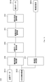
- FIG. 11 is a block diagram of the point cloud data processing unit 113, which illustrates an operation of instructing remeasurement after removing the point cloud included in the three-dimensional invalid region according to the fifth embodiment of the present invention. be.
- FIG. 11 corresponds to a modification of the third embodiment.
- the invalid area removing unit 210, the monitoring means application unit 211, and the display means application unit 212 operate in the same manner as in the third embodiment.
- the remeasurement determination unit 411 calculates the time when the point cloud can be acquired in the three-dimensional invalid region when the region exists in the three-dimensional invalid region D121, and then remeasures at that time with the remeasurement instruction D410. To the measuring device 11.
- the position of the light source at any time is estimated by referring to the orbital formula of the sun and the table. Then, based on the method for determining the three-dimensional invalid region described in the second embodiment, the range of the three-dimensional invalid region at an arbitrary time is calculated using the estimated position of the light source. The time when the area that has been the three-dimensional invalid area deviates from the three-dimensional invalid area is set as the time for remeasurement.
- the point cloud data integration unit 410 integrates the acquired point cloud data and the point cloud data acquired by remeasurement.
- An operation example is given in which a region that has been a three-dimensional invalid region is cut out from the acquired point cloud data and added to the acquired point cloud data.
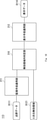
- FIG. 12 is a point cloud data processing unit 113 illustrating an operation of instructing remeasurement after removing the point cloud of the monitoring result included in the three-dimensional invalid region according to the fifth embodiment of the present invention. It is a block diagram.
- FIG. 12 corresponds to a modified example of the fourth embodiment.
- the invalid area determination unit 310, the monitoring means application unit 211, and the display means application unit 212 operate in the same manner as in the fourth embodiment.
- the remeasurement determination unit 411 operates in the same manner as described in FIG.
- the point cloud data integration unit 420 integrates the acquired abnormality information and the abnormality information acquired by remeasurement.
- the example of the integration method is the same as the description in FIG. 11, and differs in that the abnormality information is integrated.
- FIG. 13 is a point cloud data processing unit 113 illustrating an operation of instructing remeasurement after removing the point cloud of the monitoring result included in the three-dimensional invalid region according to the fifth embodiment of the present invention. It is a block diagram. FIG. 13 corresponds to a modification of the third embodiment.
- the monitoring means application unit 211, the display means application unit 212, and the point cloud data integration unit 420 operate in the same manner as described in FIG.
- the invalid area determination unit 430 outputs a remeasurement instruction when an abnormality determination exists in the three-dimensional invalid area.
- the remeasurement determination unit 431 receives a remeasurement instruction from the invalid region determination unit 430, the remeasurement determination unit 431 outputs a remeasurement instruction in the same manner as the remeasurement determination unit 411.
- the monitoring system of the fifth embodiment complements the abnormality determination in the three-dimensional invalid region to be monitored by the remeasurement at which the time is specified in the third to fourth embodiments. As a result, it becomes possible to monitor the leaked area without omission by exception handling.
- FIG. 14 is a diagram illustrating an operation of showing a three-dimensional invalid region on a monitoring screen in the point cloud data processing unit 113 according to the sixth embodiment of the present invention.
- the monitoring screen 500 represents a screen for transmitting to the observer on the display device 13.
- the measurement target display 501 indicates the measurement target, and the observer is made to visually recognize the portion determined to be abnormal.
- a point cloud display is an example.
- the monitoring result displays 502 and 503 indicate the points determined to be abnormal by the point cloud data processing unit 113.
- the gaze display 504 indicates an area corresponding to the three-dimensional invalid area, and the monitoring result display 503 is included in this area.
- the point cloud corresponding to the three-dimensional invalid area is not removed, but is displayed as an area to be watched by the observer, so that the abnormality determination included in the three-dimensional invalid area is unreliable.
- the three-dimensional invalid area is surrounded by a dotted line in FIG. 14, if the part corresponding to the three-dimensional invalid area can be visually recognized by the observer, such as by changing the color of the monitoring result display 503. , Any means.
- FIG. 15 is a block diagram of a point cloud data processing unit 113 illustrating an operation showing a three-dimensional invalid region on a monitoring screen according to a sixth embodiment of the present invention.
- the point cloud data D111 is data output from the measuring device 11.
- the three-dimensional invalid area D121 is a three-dimensional area determined by the invalid area determination unit 112.
- the monitoring means application unit 211 applies a process of determining an abnormality and a process of identifying an abnormality using the point cloud data D111.
- the display method determination unit 510 outputs abnormality information together with the display method so that the three-dimensional invalid area can be visually recognized on the display device 13.
- the display means application unit 212 outputs the abnormality information output from the display method determination unit 510 and the display information of the three-dimensional invalid area as display data D114 that can be identified by the display device in the subsequent stage.
- the monitoring system of the sixth embodiment displays the three-dimensional invalid area in a form that can be visually recognized by the observer as an exception handling method for the three-dimensional invalid area in the second embodiment.
- a monitoring system that informs the observer that the information is unreliable even if an abnormality is determined in the area disturbed by the light source.
- the present invention has been described as a hardware configuration in the above-described first to sixth embodiments, the present invention is not limited thereto.
- the present invention can also realize the processing of each component by causing a CPU (Central Processing Unit) to execute a computer program.
- a CPU Central Processing Unit
- Non-temporary computer-readable media include various types of tangible storage mediums.
- Examples of non-temporary computer-readable media include magnetic recording media (eg, flexible disks, magnetic tapes, hard disk drives), magneto-optical recording media (eg, magneto-optical disks), CD-ROMs (ReadOnlyMemory), CD-Rs, Includes CD-R / W, DVD (DigitalVersatileDisc), semiconductor memory (for example, mask ROM, PROM (ProgrammableROM), EPROM (ErasablePROM), flash ROM, RAM (RandomAccessMemory)).
- magnetic recording media eg, flexible disks, magnetic tapes, hard disk drives
- magneto-optical recording media eg, magneto-optical disks
- CD-ROMs ReadOnlyMemory
- CD-Rs Includes CD-R / W, DVD (DigitalVersatileDisc)
- semiconductor memory for example, mask ROM, PROM (ProgrammableROM), EPROM (ErasablePROM), flash
- the program may also be supplied to the computer by various types of transient computer readable medium.
- Examples of temporary computer readable media include electrical, optical, and electromagnetic waves.
- the temporary computer-readable medium can supply the program to the computer via a wired communication path such as an electric wire and an optical fiber, or a wireless communication path.
- (Appendix 1) A straight line calculation means for calculating a straight line connecting the 3D coordinates of the light source and the 3D coordinates of the 3D measuring device for measuring the measurement target.
- An invalid region determining means for determining a three-dimensional invalid region in which the acquired point cloud data acquired by the three-dimensional measuring device is invalid based on the straight line
- a point cloud data processing means for monitoring the measurement target based on the acquired point cloud data and the three-dimensional invalid region, and A monitoring system equipped with.
- Appendix 2 A reflected luminance value is assigned to each point of the acquired point cloud data.
- the invalid area determination means is The point group data around the straight line is extracted from the acquired point group data based on the straight line, the gradient of the reflected brightness value is calculated from the extracted point group data around the straight line, and the absolute value of the gradient is predetermined. A region larger than the value is determined as the three-dimensional invalid region.
- the monitoring system described in Appendix 1. (Appendix 3) The invalid area determination means is Based on the illuminance value acquired by the illuminance measuring device close to the three-dimensional measuring device, the three-dimensional invalid region with the straight line as the axis is determined.
- the monitoring system according to any one of Supplementary Provisions 1 and 2.
- the point cloud data processing means is An invalid area removing means for generating effective point cloud data by removing the point cloud data included in the three-dimensional invalid area from the acquired point cloud data.
- a monitoring means application means that identifies an abnormal location based on the effective point cloud data and outputs the specified result as monitoring processing data.
- the monitoring system according to any one of Supplementary note 1 to 3, comprising the above.
- the point cloud data processing means is A monitoring means application means that identifies an abnormal part based on the acquired point cloud data and outputs a specific result as a monitoring processing data candidate.
- An invalid area removing means for removing the abnormal portion included in the three-dimensional invalid area from the monitoring processing data candidate and outputting it as monitoring processing data.
- the monitoring system according to any one of Supplementary note 1 to 3, comprising the above.
- the monitoring system is A remeasurement determination means for calculating a time when effective measurement is possible in the three-dimensional invalid region and transmitting a measurement instruction at the time to the three-dimensional measuring device.
- a point cloud data integration means for integrating the point cloud data included in the three-dimensional invalid region among the remeasurement point cloud data which is the acquired point cloud data at the time into the effective point cloud data.
- the monitoring system according to Appendix 4, further comprising.
- the monitoring system is A remeasurement determination means for calculating a time when effective measurement is possible in the three-dimensional invalid region and transmitting a measurement instruction at the time to the three-dimensional measuring device.
- An abnormal part is specified based on the remeasurement point cloud data which is the acquired point cloud data at the time, and the abnormal part included in the three-dimensional invalid region of the remeasurement monitoring processing data which is the specific result is monitored.
- Point cloud data integration means to integrate into processed data The monitoring system according to Appendix 5, further comprising. (Appendix 8) The monitoring system is When the monitoring processing data candidate includes the abnormal portion included in the three-dimensional invalid area, the time at which effective measurement is possible in the three-dimensional invalid area is calculated, and the measurement instruction at the time is given.
- Remeasurement decision means to be transmitted to the 3D measuring device, An abnormal part is specified based on the remeasurement point cloud data which is the acquired point cloud data at the time, and the abnormal part included in the three-dimensional invalid region of the remeasurement monitoring processing data which is the specific result is monitored.
- Point cloud data integration means to integrate into processed data, The monitoring system according to Appendix 5, further comprising. (Appendix 9)
- the point cloud data processing means is A monitoring means application means that identifies an abnormal location based on the acquired point cloud data and outputs the specified result as a monitoring processing data candidate.
- the monitoring system according to any one of Supplementary note 1 to 3, comprising the above.
- (Appendix 10) Calculate a straight line connecting the 3D coordinates of the light source and the 3D coordinates of the 3D measuring device that measures the measurement target.
- a three-dimensional invalid region in which the acquired point cloud data acquired by the three-dimensional measuring device is invalid is determined based on the straight line.
- the measurement target is monitored based on the acquired point cloud data and the three-dimensional invalid region.
- Monitoring method (Appendix 11) On the computer The process of calculating a straight line connecting the 3D coordinates of the light source and the 3D coordinates of the 3D measuring device that measures the measurement target.
- Monitoring system 11 Measuring device 12: Data processing device 13: Display device 100: Measurement target 101: Three-dimensional measuring device 102: Light source 103: Straight line 104: Three-dimensional invalid area 111: Straight line calculation unit 112: Invalid area Determination unit 113: Point group data processing unit 210: Invalid area removal unit 211: Monitoring means application unit 212: Display means application unit 310: 430: Invalid area determination unit 200, 201: Measurement target point group 300, 301, 302: Monitoring result point group 410, 420: Point group data integration unit 411, 431: Remeasurement determination unit 420: Point group data integration unit 500: Monitoring screen 501: Measurement target display 502, 503: Monitoring result display 504: Gaze display 510: Display method determination unit
Landscapes
- Physics & Mathematics (AREA)
- Engineering & Computer Science (AREA)
- General Physics & Mathematics (AREA)
- Electromagnetism (AREA)
- Computer Networks & Wireless Communication (AREA)
- Radar, Positioning & Navigation (AREA)
- Remote Sensing (AREA)
- Length Measuring Devices By Optical Means (AREA)
Priority Applications (3)
| Application Number | Priority Date | Filing Date | Title |
|---|---|---|---|
| US18/025,808 US20230333250A1 (en) | 2020-09-16 | 2020-09-16 | Monitoring system, method, and non-transitory computer-readable medium storing program |
| PCT/JP2020/035087 WO2022059093A1 (ja) | 2020-09-16 | 2020-09-16 | 監視システム、方法、及びプログラムが格納された非一時的なコンピュータ可読媒体 |
| JP2022550091A JP7537502B2 (ja) | 2020-09-16 | 2020-09-16 | 監視システム、方法、及びプログラム |
Applications Claiming Priority (1)
| Application Number | Priority Date | Filing Date | Title |
|---|---|---|---|
| PCT/JP2020/035087 WO2022059093A1 (ja) | 2020-09-16 | 2020-09-16 | 監視システム、方法、及びプログラムが格納された非一時的なコンピュータ可読媒体 |
Publications (1)
| Publication Number | Publication Date |
|---|---|
| WO2022059093A1 true WO2022059093A1 (ja) | 2022-03-24 |
Family
ID=80776559
Family Applications (1)
| Application Number | Title | Priority Date | Filing Date |
|---|---|---|---|
| PCT/JP2020/035087 Ceased WO2022059093A1 (ja) | 2020-09-16 | 2020-09-16 | 監視システム、方法、及びプログラムが格納された非一時的なコンピュータ可読媒体 |
Country Status (3)
| Country | Link |
|---|---|
| US (1) | US20230333250A1 (https=) |
| JP (1) | JP7537502B2 (https=) |
| WO (1) | WO2022059093A1 (https=) |
Citations (5)
| Publication number | Priority date | Publication date | Assignee | Title |
|---|---|---|---|---|
| JP2005249743A (ja) * | 2004-03-08 | 2005-09-15 | Omron Corp | レーダ装置 |
| JP2006023178A (ja) * | 2004-07-07 | 2006-01-26 | Olympus Corp | 3次元計測方法及び装置 |
| JP2011205399A (ja) * | 2010-03-25 | 2011-10-13 | Fujifilm Corp | 画像処理装置および方法,ならびに画像処理プログラム |
| JP2017009558A (ja) * | 2015-06-26 | 2017-01-12 | 株式会社トプコン | レーザスキャナ制御装置、レーザスキャナ制御方法およびレーザスキャナ制御用プログラム |
| JP2018165726A (ja) * | 2014-11-19 | 2018-10-25 | 首都高技術株式会社 | 点群データ利用システム |
-
2020
- 2020-09-16 WO PCT/JP2020/035087 patent/WO2022059093A1/ja not_active Ceased
- 2020-09-16 US US18/025,808 patent/US20230333250A1/en active Pending
- 2020-09-16 JP JP2022550091A patent/JP7537502B2/ja active Active
Patent Citations (5)
| Publication number | Priority date | Publication date | Assignee | Title |
|---|---|---|---|---|
| JP2005249743A (ja) * | 2004-03-08 | 2005-09-15 | Omron Corp | レーダ装置 |
| JP2006023178A (ja) * | 2004-07-07 | 2006-01-26 | Olympus Corp | 3次元計測方法及び装置 |
| JP2011205399A (ja) * | 2010-03-25 | 2011-10-13 | Fujifilm Corp | 画像処理装置および方法,ならびに画像処理プログラム |
| JP2018165726A (ja) * | 2014-11-19 | 2018-10-25 | 首都高技術株式会社 | 点群データ利用システム |
| JP2017009558A (ja) * | 2015-06-26 | 2017-01-12 | 株式会社トプコン | レーザスキャナ制御装置、レーザスキャナ制御方法およびレーザスキャナ制御用プログラム |
Also Published As
| Publication number | Publication date |
|---|---|
| JPWO2022059093A1 (https=) | 2022-03-24 |
| JP7537502B2 (ja) | 2024-08-21 |
| US20230333250A1 (en) | 2023-10-19 |
Similar Documents
| Publication | Publication Date | Title |
|---|---|---|
| EP2907157B1 (en) | Detecting defects on a wafer using defect-specific information | |
| JP6696278B2 (ja) | ドリフト検査装置 | |
| US10666927B2 (en) | Method and device for inspection of an asset | |
| US10297021B2 (en) | Defect quantification method, defect quantification device, and defect evaluation value display device | |
| JP2022509137A (ja) | 深層畳み込みニューラルネットワークを用いたレーザ加工システムの加工誤差の検出 | |
| KR102223706B1 (ko) | 제조된 컴포넌트 결함을 국부 적응 문턱값을 사용하여 식별하기 위한 시스템, 방법 및 컴퓨터 프로그램 제품 | |
| JP2020008501A (ja) | 表面欠陥検出装置及び表面欠陥検出方法 | |
| US11139216B2 (en) | System, method and non-transitory computer readable medium for tuning sensitivities of, and determining a process window for, a modulated wafer | |
| KR101941585B1 (ko) | 인공지능 기반의 검사를 위한 임베디드 시스템, 제어 방법 및 이를 포함하는 검사 시스템 | |
| EP3270102B1 (en) | Shape inspection method, shape inspection device, and program | |
| CN110617876B (zh) | 电力设备异响定位方法 | |
| KR20210021171A (ko) | 제품 검사 장치 및 방법과, 이를 이용한 반도체 제조 시스템 및 제조 방법 | |
| WO2022059093A1 (ja) | 監視システム、方法、及びプログラムが格納された非一時的なコンピュータ可読媒体 | |
| JP5262070B2 (ja) | 被検査物の真円度測定方法 | |
| JP2015059817A (ja) | 二次電池の外観検査方法及び二次電池の外観検査装置 | |
| JP6852472B2 (ja) | トロリ線の摺動面幅検出装置及び方法 | |
| US12339367B2 (en) | Detection device, determination method, and non-transitory computer-readable medium | |
| JP7447906B2 (ja) | 表面異常検知装置、システム、方法、及びプログラム | |
| JP5214323B2 (ja) | 目視検査装置及び方法 | |
| WO2020263972A1 (en) | Methods, systems, and devices for monitoring a web of material translating along a travel path | |
| US20250102674A1 (en) | Identification system, identification method, and storage medium | |
| JP2006292500A (ja) | 表面検査方法及び表面検査装置 | |
| CN115499582A (zh) | 表面灰尘检测设备的对焦方法、装置、设备及存储介质 | |
| JP2025071417A (ja) | 欠陥検査システム及び欠陥検査方法 | |
| JP2023153623A (ja) | 温度計測システム、温度計測装置及び温度計測方法 |
Legal Events
| Date | Code | Title | Description |
|---|---|---|---|
| 121 | Ep: the epo has been informed by wipo that ep was designated in this application |
Ref document number: 20954079 Country of ref document: EP Kind code of ref document: A1 |
|
| ENP | Entry into the national phase |
Ref document number: 2022550091 Country of ref document: JP Kind code of ref document: A |
|
| NENP | Non-entry into the national phase |
Ref country code: DE |
|
| 122 | Ep: pct application non-entry in european phase |
Ref document number: 20954079 Country of ref document: EP Kind code of ref document: A1 |