WO2022054537A1 - 水処理システム、情報処理装置、情報処理方法およびプログラム - Google Patents
水処理システム、情報処理装置、情報処理方法およびプログラム Download PDFInfo
- Publication number
- WO2022054537A1 WO2022054537A1 PCT/JP2021/030530 JP2021030530W WO2022054537A1 WO 2022054537 A1 WO2022054537 A1 WO 2022054537A1 JP 2021030530 W JP2021030530 W JP 2021030530W WO 2022054537 A1 WO2022054537 A1 WO 2022054537A1
- Authority
- WO
- WIPO (PCT)
- Prior art keywords
- water treatment
- concentration
- removal rate
- water
- treatment device
- Prior art date
- Legal status (The legal status is an assumption and is not a legal conclusion. Google has not performed a legal analysis and makes no representation as to the accuracy of the status listed.)
- Ceased
Links
Images




Classifications
-
- C—CHEMISTRY; METALLURGY
- C02—TREATMENT OF WATER, WASTE WATER, SEWAGE, OR SLUDGE
- C02F—TREATMENT OF WATER, WASTE WATER, SEWAGE, OR SLUDGE
- C02F1/00—Treatment of water, waste water, or sewage
- C02F1/008—Control or steering systems not provided for elsewhere in subclass C02F
-
- C—CHEMISTRY; METALLURGY
- C02—TREATMENT OF WATER, WASTE WATER, SEWAGE, OR SLUDGE
- C02F—TREATMENT OF WATER, WASTE WATER, SEWAGE, OR SLUDGE
- C02F9/00—Multistage treatment of water, waste water or sewage
-
- G—PHYSICS
- G06—COMPUTING OR CALCULATING; COUNTING
- G06Q—INFORMATION AND COMMUNICATION TECHNOLOGY [ICT] SPECIALLY ADAPTED FOR ADMINISTRATIVE, COMMERCIAL, FINANCIAL, MANAGERIAL OR SUPERVISORY PURPOSES; SYSTEMS OR METHODS SPECIALLY ADAPTED FOR ADMINISTRATIVE, COMMERCIAL, FINANCIAL, MANAGERIAL OR SUPERVISORY PURPOSES, NOT OTHERWISE PROVIDED FOR
- G06Q10/00—Administration; Management
- G06Q10/04—Forecasting or optimisation specially adapted for administrative or management purposes, e.g. linear programming or "cutting stock problem"
-
- G—PHYSICS
- G06—COMPUTING OR CALCULATING; COUNTING
- G06Q—INFORMATION AND COMMUNICATION TECHNOLOGY [ICT] SPECIALLY ADAPTED FOR ADMINISTRATIVE, COMMERCIAL, FINANCIAL, MANAGERIAL OR SUPERVISORY PURPOSES; SYSTEMS OR METHODS SPECIALLY ADAPTED FOR ADMINISTRATIVE, COMMERCIAL, FINANCIAL, MANAGERIAL OR SUPERVISORY PURPOSES, NOT OTHERWISE PROVIDED FOR
- G06Q50/00—Information and communication technology [ICT] specially adapted for implementation of business processes of specific business sectors, e.g. utilities or tourism
- G06Q50/06—Energy or water supply
-
- C—CHEMISTRY; METALLURGY
- C02—TREATMENT OF WATER, WASTE WATER, SEWAGE, OR SLUDGE
- C02F—TREATMENT OF WATER, WASTE WATER, SEWAGE, OR SLUDGE
- C02F1/00—Treatment of water, waste water, or sewage
- C02F1/28—Treatment of water, waste water, or sewage by sorption
- C02F1/283—Treatment of water, waste water, or sewage by sorption using coal, charred products, or inorganic mixtures containing them
-
- C—CHEMISTRY; METALLURGY
- C02—TREATMENT OF WATER, WASTE WATER, SEWAGE, OR SLUDGE
- C02F—TREATMENT OF WATER, WASTE WATER, SEWAGE, OR SLUDGE
- C02F1/00—Treatment of water, waste water, or sewage
- C02F1/30—Treatment of water, waste water, or sewage by irradiation
- C02F1/32—Treatment of water, waste water, or sewage by irradiation with ultraviolet light
-
- C—CHEMISTRY; METALLURGY
- C02—TREATMENT OF WATER, WASTE WATER, SEWAGE, OR SLUDGE
- C02F—TREATMENT OF WATER, WASTE WATER, SEWAGE, OR SLUDGE
- C02F1/00—Treatment of water, waste water, or sewage
- C02F1/44—Treatment of water, waste water, or sewage by dialysis, osmosis or reverse osmosis
- C02F1/441—Treatment of water, waste water, or sewage by dialysis, osmosis or reverse osmosis by reverse osmosis
-
- C—CHEMISTRY; METALLURGY
- C02—TREATMENT OF WATER, WASTE WATER, SEWAGE, OR SLUDGE
- C02F—TREATMENT OF WATER, WASTE WATER, SEWAGE, OR SLUDGE
- C02F1/00—Treatment of water, waste water, or sewage
- C02F1/44—Treatment of water, waste water, or sewage by dialysis, osmosis or reverse osmosis
- C02F1/444—Treatment of water, waste water, or sewage by dialysis, osmosis or reverse osmosis by ultrafiltration or microfiltration
-
- C—CHEMISTRY; METALLURGY
- C02—TREATMENT OF WATER, WASTE WATER, SEWAGE, OR SLUDGE
- C02F—TREATMENT OF WATER, WASTE WATER, SEWAGE, OR SLUDGE
- C02F1/00—Treatment of water, waste water, or sewage
- C02F1/72—Treatment of water, waste water, or sewage by oxidation
- C02F1/76—Treatment of water, waste water, or sewage by oxidation with halogens or compounds of halogens
-
- C—CHEMISTRY; METALLURGY
- C02—TREATMENT OF WATER, WASTE WATER, SEWAGE, OR SLUDGE
- C02F—TREATMENT OF WATER, WASTE WATER, SEWAGE, OR SLUDGE
- C02F1/00—Treatment of water, waste water, or sewage
- C02F1/42—Treatment of water, waste water, or sewage by ion-exchange
- C02F2001/422—Treatment of water, waste water, or sewage by ion-exchange using anionic exchangers
-
- C—CHEMISTRY; METALLURGY
- C02—TREATMENT OF WATER, WASTE WATER, SEWAGE, OR SLUDGE
- C02F—TREATMENT OF WATER, WASTE WATER, SEWAGE, OR SLUDGE
- C02F1/00—Treatment of water, waste water, or sewage
- C02F1/42—Treatment of water, waste water, or sewage by ion-exchange
- C02F2001/425—Treatment of water, waste water, or sewage by ion-exchange using cation exchangers
-
- C—CHEMISTRY; METALLURGY
- C02—TREATMENT OF WATER, WASTE WATER, SEWAGE, OR SLUDGE
- C02F—TREATMENT OF WATER, WASTE WATER, SEWAGE, OR SLUDGE
- C02F2101/00—Nature of the contaminant
- C02F2101/10—Inorganic compounds
- C02F2101/16—Nitrogen compounds, e.g. ammonia
-
- C—CHEMISTRY; METALLURGY
- C02—TREATMENT OF WATER, WASTE WATER, SEWAGE, OR SLUDGE
- C02F—TREATMENT OF WATER, WASTE WATER, SEWAGE, OR SLUDGE
- C02F2103/00—Nature of the water, waste water, sewage or sludge to be treated
- C02F2103/02—Non-contaminated water, e.g. for industrial water supply
- C02F2103/04—Non-contaminated water, e.g. for industrial water supply for obtaining ultra-pure water
-
- C—CHEMISTRY; METALLURGY
- C02—TREATMENT OF WATER, WASTE WATER, SEWAGE, OR SLUDGE
- C02F—TREATMENT OF WATER, WASTE WATER, SEWAGE, OR SLUDGE
- C02F2209/00—Controlling or monitoring parameters in water treatment
- C02F2209/005—Processes using a programmable logic controller [PLC]
-
- C—CHEMISTRY; METALLURGY
- C02—TREATMENT OF WATER, WASTE WATER, SEWAGE, OR SLUDGE
- C02F—TREATMENT OF WATER, WASTE WATER, SEWAGE, OR SLUDGE
- C02F2209/00—Controlling or monitoring parameters in water treatment
- C02F2209/005—Processes using a programmable logic controller [PLC]
- C02F2209/006—Processes using a programmable logic controller [PLC] comprising a software program or a logic diagram
-
- C—CHEMISTRY; METALLURGY
- C02—TREATMENT OF WATER, WASTE WATER, SEWAGE, OR SLUDGE
- C02F—TREATMENT OF WATER, WASTE WATER, SEWAGE, OR SLUDGE
- C02F2209/00—Controlling or monitoring parameters in water treatment
- C02F2209/20—Total organic carbon [TOC]
-
- Y—GENERAL TAGGING OF NEW TECHNOLOGICAL DEVELOPMENTS; GENERAL TAGGING OF CROSS-SECTIONAL TECHNOLOGIES SPANNING OVER SEVERAL SECTIONS OF THE IPC; TECHNICAL SUBJECTS COVERED BY FORMER USPC CROSS-REFERENCE ART COLLECTIONS [XRACs] AND DIGESTS
- Y02—TECHNOLOGIES OR APPLICATIONS FOR MITIGATION OR ADAPTATION AGAINST CLIMATE CHANGE
- Y02A—TECHNOLOGIES FOR ADAPTATION TO CLIMATE CHANGE
- Y02A20/00—Water conservation; Efficient water supply; Efficient water use
- Y02A20/152—Water filtration
Definitions
- the present invention relates to a water treatment system, an information processing device, an information processing method and a program.
- the impurity concentration of the water supplied to the use point is measured using a dedicated densitometer.
- the ion detection device detects the ion concentration of water that has passed through the ion exchange resin device that removes ionic substances in ultrapure water. Then, a technique of bypassing the ion exchange resin device based on the result detected by the ion detection device is considered (see, for example, Patent Document 1).
- An object of the present invention is to provide a water treatment system, an information processing device, an information processing method and a program capable of grasping the water quality of the supplied water in advance.
- the present invention has a water treatment device for removing impurities from the supplied water and an information processing device.
- the information processing device is Predicted value of the concentration of the impurities contained in the water supplied from the water treatment device when the current supplied water is treated by the water treatment device based on the removal rate for removing the impurities in the water treatment device. It is a water treatment system having a concentration calculation unit for calculating.
- the present invention is based on the removal rate of removing impurities in the water treatment device for removing impurities from the supplied water, from the water treatment device when the current supplied water is treated by the water treatment device. It is an information processing apparatus having a concentration calculation unit for calculating a predicted value of the concentration of the impurities contained in the supplied water.
- the present invention is based on the removal rate for removing impurities in the water treatment device for removing impurities from the supplied water, from the water treatment device when the current supplied water is treated by the water treatment device. It is an information processing method that performs a process of calculating a predicted value of the concentration of the impurities contained in the supplied water.
- the present invention applies to a computer. Included in the water supplied from the water treatment device when the current supply water is treated by the water treatment device, based on the removal rate for removing the impurities in the water treatment device that removes impurities from the supplied water. This is a program for executing a procedure for calculating a predicted value of the concentration of the impurities.
- the water quality of the supplied water can be grasped in advance.
- FIG. 1st Embodiment of the water treatment system of this invention It is a figure which shows the 1st Embodiment of the water treatment system of this invention. It is a figure which shows an example of the internal structure of the information processing apparatus shown in FIG. It is a figure which shows an example of the TOC prediction value in the water treatment apparatus calculated by the concentration calculation unit shown in FIG. It is a figure which shows an example of the structure of the specific water treatment system in this embodiment. It is a figure which shows the 2nd Embodiment of the water treatment system of this invention. It is a figure which shows an example of the internal structure of the information processing apparatus shown in FIG. It is a figure which shows an example of the information which shows the past use record stored in the database shown in FIG.
- FIG. 1 is a diagram showing a first embodiment of the water treatment system of the present invention.
- the water treatment system in the present embodiment includes a plurality of water treatment devices 100-1 to 100-5, a plurality of concentration measuring units 200-1 to 200-6, and an information processing device 300.
- the case where the number of the water treatment apparatus 100-1 to 100-5 is 5 is taken as an example.
- the case where the number of the concentration measuring units 200-1 to 200-6 is 6 is taken as an example.
- the number of each of the water treatment apparatus and the concentration measuring unit of the water treatment system of the present invention is not limited.
- the water treatment devices 100-1 to 100-5 are connected (arranged) in series.
- the water treatment devices 100-1 to 100-5 each remove impurities from the supplied water over a predetermined time.
- this predetermined time for example, after water flows into each of the water treatment devices 100-1 to 100-5, the predetermined treatment is performed on the water, and the treated water is discharged to the outside. It is the residence time until. Further, this predetermined time is a time approximately determined for each of the water treatment devices 100-1 to 100-5.
- the residence time in the water treatment apparatus 100-1 is about 3 hours.
- the residence time in the water treatment apparatus 100-2 is about 2 hours.
- the residence time of the water treatment devices 100-3 to 100-5 is about 1 hour.
- FIG. 1 an example in which the water treatment devices 100-1 to 100-5 are connected in series is shown. For example, even if the water treatment devices 100-1 to 100-5 are connected in parallel, it suffices if the removal rate described below can be calculated.
- the concentration measuring unit 200-1 measures the concentration of impurities contained in the water supplied to the water treatment device 100-1, that is, the water on the inlet side of the water treatment device 100-1.
- Each of the concentration measuring units 200-2 to 200-5 is water supplied from each of the water treatment devices 100-1 to 100-4, that is, water on the outlet side of each of the water treatment devices 100-1 to 100-4 (in other words).
- the concentration of impurities contained in the water at the inlet side of each of the water treatment devices 100-2 to 100-5) is measured.
- the concentration measuring unit 200-6 measures the concentration of impurities contained in the water supplied from the water treatment device 100-5, that is, the water on the outlet side of the water treatment device 100-5.
- each of the concentration measuring units 200-1 to 200-6 may measure at intervals shorter than the predetermined time for each of the water treatment devices 100-1 to 100-5 to remove impurities. For example, when each of the water treatment devices 100-1 to 100-5 treats water with the respective residence time as described above, the concentration measuring unit 200-1 has a time interval shorter than 3 hours, and the concentration measuring unit 200- 2 is a time interval shorter than 2 hours, and concentration measuring units 200-3 to 200-6 are time intervals shorter than 1 hour, and the concentration of impurities contained in the water supplied to the water treatment device 100-1 and water. The concentration of impurities contained in the water supplied from each of the treatment devices 100-1 to 100-5 is measured.
- the concentration of impurities measured by the concentration measuring units 200-1 to 200-6 is the concentration of TOC (Total Organic Carbon: total organic carbon) contained in water and the concentration of urea.
- the reason why the concentration measuring units 200-1 to 200-6 are provided for each of the water treatment devices 100-1 to 100-5 is to calculate the removal rate of impurities in the water treatment devices 100-1 to 100-5.
- the information processing apparatus 300 acquires concentration information indicating the concentration measured by the concentration measuring units 200-1 to 200-6.
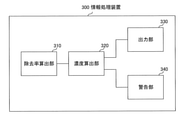
- FIG. 2 is a diagram showing an example of the internal configuration of the information processing apparatus 300 shown in FIG. As shown in FIG. 2, the information processing apparatus 300 shown in FIG. 1 has a removal rate calculation unit 310, a concentration calculation unit 320, an output unit 330, and a warning unit 340. Note that FIG. 2 shows only the main components related to the present embodiment among the components included in the information processing apparatus 300 shown in FIG.
- the removal rate calculation unit 310 calculates the removal rate for removing impurities in each of the water treatment devices 100-1 to 100-5.
- the removal rate calculation unit 310 acquires concentration information indicating the concentration measured by the concentration measurement units 200-1 to 200-6.
- the removal rate calculation unit 310 calculates the removal rate of each of the water treatment devices 100-1 to 100-5 based on the concentration indicated by the acquired concentration information.
- the removal rate calculation unit 310 is the concentration of impurities contained in the water supplied to each of the water treatment devices 100-1 to 100-5 and the water measured by the concentration measurement units 200-1 to 200-6.
- the removal rate of each of the water treatment devices 100-1 to 100-5 is calculated based on the concentration of impurities contained in the water supplied from each of the treatment devices 100-1 to 100-5.
- the removal rate calculation unit 310 calculates the removal rate at time intervals in which the concentration measuring units 200-1 to 200-6 measure the concentration.
- the removal rate calculated by the removal rate calculation unit 310 is a storage means provided in the information processing device 300 (for example, a storage medium such as a memory) or an external storage device capable of reading information from the information processing device 300. Etc. are stored in the storage unit.
- the removal rate calculated by the removal rate calculation unit 310 By storing the removal rate calculated by the removal rate calculation unit 310 in such a device or device, it is possible to send a warning when the removal rate is significantly reduced (worse) from the removal rate calculated in the past (previous time). can. Further, by storing the removal rate calculated by the removal rate calculation unit 310 in such an apparatus or device, the remaining life of the water treatment apparatus can be predicted. Further, by storing the removal rate calculated by the removal rate calculation unit 310 in such a device or device, the removal rate for a predetermined time (for example, one minute before the current time) can be stored in the concentration calculation unit 320. Can be used for calculations in.
- a predetermined time for example, one minute before the current time
- the concentration calculation unit 320 is the most downstream of the water treatment devices 100-1 to 100-5 based on the removal rates of the water treatment devices 100-1 to 100-5 calculated by the removal rate calculation unit 310 before a predetermined time.
- the concentration of impurities contained in the water supplied from the water treatment device connected to the water treatment device (that is, the water treatment system composed of the water treatment devices 100-1 to 100-5) is calculated.
- the water treatment device connected to the most downstream is the water treatment device 100-5.
- the concentration calculation unit 320 indicates the concentration of impurities contained in the water flowing into the water treatment device connected to the uppermost stream, and the removal rate calculation unit 310 before a predetermined time (for example, the time in the past closest to the present) 1.
- the concentration calculation unit 320 calculates the concentration of TOC contained in the water flowing into the water treatment device arranged at the uppermost stream and the water treatment calculated by the removal rate calculation unit 310 before a predetermined time (for example, 1 minute before). Based on the removal rate of the devices 100-1 to 100-5, the predicted value of the TOC concentration of the water supplied from each of the water treatment devices 100-1 to 100-5 is calculated. When calculating the concentration, the concentration calculation unit 320 may use the removal rate calculated by the removal rate calculation unit 310 or the removal rate preset for each of the water treatment devices 100-1 to 100-5. good.
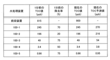
- FIG. 3 is a diagram showing an example of TOC predicted values (predicted values of TOC concentration) in the water treatment devices 100-1 to 100-5 calculated by the concentration calculation unit 320 shown in FIG.
- a water tank in which the water to be treated is stored is arranged upstream (previous stage) of the water treatment apparatus 100-1.
- the water to be treated is supplied to the water treatment apparatus 100-1 from the water tank in which the water to be treated is stored.
- the removal rate 1 minute ago is the water treatment device 100-1 to 100-5 calculated by the removal rate calculation unit 310 based on the concentration measured by the concentration measurement units 200-1 to 200-6 1 minute ago. It is the value of the removal rate.
- the TOC value contained in the water supplied to the water treatment device 100-1 from the previous stage device is 900 (ppb), and the removal rate of the water treatment device 100-1 one minute ago is 70 (%).
- the concentration calculation unit 320 900 (TOC value) x (1-0.7 (removal rate 1 minute ago)) 270
- the TOC predicted value of the water supplied from the water treatment apparatus 100-1 is calculated.
- TOC contains urea.
- the removal rate of urea is significantly different (low) from the removal rate of impurities such as other organic carbons. Therefore, the calculation of the urea removal rate may be performed separately from the calculation of the TOC removal rate. In such a calculation, it is necessary to consider the removal rate of TOC, the removal rate of urea, and the removal rate of TOC excluding urea. As an empirical value actually measured, 20% of the urea concentration may be detected as TOC. In this way, rather than calculating the removal rate using the TOC value on the inlet side and the TOC value on the outlet side of the water treatment device as they are, the removal rate of the urea component and the removal rate of other components are calculated. It is possible to obtain a more accurate TOC removal rate value by calculating each. That is, it is preferable to calculate the removal rate using the value obtained by subtracting the urea component from the TOC value on the inlet side of the water treatment device.
- the output unit 330 outputs the concentration information indicating the concentration calculated by the concentration calculation unit 320.
- the output unit 330 may display the concentration information indicating the concentration calculated by the concentration calculation unit 320. Further, the output unit 330 may transmit the concentration information indicating the concentration calculated by the concentration calculation unit 320 to another device. Further, the output unit 330 may print the density information indicating the density calculated by the density calculation unit 320.
- the warning unit 340 compares the concentration calculated by the concentration calculation unit 320 with the preset threshold value. As a result of comparison, the warning unit 340 outputs a predetermined warning when the concentration calculated by the concentration calculation unit 320 exceeds the threshold value. At this time, the warning unit 340 outputs a signal for performing a process for lowering the density. This warning may display a process for lowering the density at the same time as outputting a predetermined alert from the information processing apparatus 300. The process for lowering the concentration will be described later.
- FIG. 4 is a diagram showing an example of a specific configuration of a water treatment system in this embodiment.
- the water treatment system shown in FIG. 4 includes a raw water tank 1001, a filter 1002, a filtered water tank 1003, an activated carbon tower 1004, a K tower 1005, a D tower 1006, an A tower 1007, and a pure water tank 1008.
- the RO device 1009, the RO water tank 1010, the UV oxidation device 1011, the SB-P tower 1012, the ultrapure water tank 1013, the UV oxidation device 1014, and the CP + UF1015 are water treatment devices or means for performing water treatment in series. It is connected.
- Raw water and reclaimed water, which are the water to be treated, are supplied to the raw water tank 1001.
- a urea decomposing agent is injected into the raw water tank 1001 in order to remove urea in the water.
- the urea decomposition agent include hypobromous acid (for example, hypobromous acid, hypochlorous acid, hypoiodous acid, etc.).
- hypobromous acid include sodium hypobromous acid.
- the water flowing out of the raw water tank 1001 is filtered by the filter 1002.
- the filtered water is supplied to the filtered water tank 1003. Recovered water is also supplied to the filtered water tank 1003.
- the water flowing out of the filtered water tank 1003 is supplied to the activated carbon tower 1004, which is a TOC removing device.
- the water treated in the activated carbon tower 1004 is supplied to the K tower 1005, which is a strongly acidic cation exchange resin packed tower.
- the water treated in the K tower 1005 is supplied to the D tower 1006 which is a decarboxylation tower. Air is injected into the D tower 1006 in order to remove carbon dioxide gas in the water. VOCs (Volatile Organic Compounds) contained in this air adversely affect the removal of TOC in the D tower 1006.
- the water treated in the D tower 1006 is supplied to the A tower 1007, which is a strongly basic anion exchange resin packed tower.
- the water treated in Tower A 1007 is stored in a pure water tank 1008 as pure water.
- the pure water stored in the pure water tank 1008 is supplied to the RO device 1009 that performs reverse osmosis membrane filtration.
- the flow rate of the membrane permeated water in the RO device 1009 affects the removal of the TOC in the RO device 1009.
- the water treated by the RO device 1009 is stored in the RO water tank 1010.
- the water stored in the RO water tank 1010 is supplied to the UV oxidizing device 1011 which is an ultraviolet (UV: UltraViolet) oxidizing device and treated.
- the water treated by the UV oxidizing apparatus 1011 is supplied to the SB-P tower 1012.
- the water treated in the SB-P tower 1012 is stored in the ultrapure water tank 1013 as ultrapure water.
- the ultrapure water stored in the ultrapure water tank 1013 is supplied to the UV oxidizing device 1014, which is an ultraviolet oxidizing device, and processed.
- the water treated by the UV oxidizing device 1014 is supplied to CP + UF1015, which is a non-regenerative ion exchange device (CP: Cartridge Polisher) and an ultrafiltration device (UF: Ultrafiltration membrane), and is treated.
- CP + UF1015 is a non-regenerative ion exchange device (CP: Cartridge Polisher) and an ultrafiltration device (UF: Ultrafiltration membrane), and is treated.
- CP + UF1015 is a non-regenerative ion exchange device (CP: Cartridge Polisher) and an ultrafiltration device (UF: Ultrafiltration membrane), and is treated.
- CP + UF1015 is a non-regenerative ion exchange device (CP: Cartridge Polisher) and an ultrafiltration device (UF: Ultrafiltration membrane), and is treated.
- CP + UF1015 the treated water is supplied from the system to
- the processing for reducing the density output by the warning unit 340 includes the following.
- the series is an operation series provided in the water treatment devices 100-1 to 100-5 for removing impurities.
- a plurality of series are provided in parallel in the water treatment devices 100-1 to 100-5. It is provided so that the series used for operation can be switched among the plurality of series.
- -Do not accept reclaimed water in the raw water tank 1001. -Increase the amount of urea degrading agent injected to remove urea.
- the information processing apparatus 300 uses the current supply water as the water treatment apparatus 100-1 to 100-5 based on the removal rates of the water treatment apparatus 100-1 to 100-5 calculated before a predetermined time.
- the concentration of impurities contained in the water supplied from the water treatment apparatus 100-5 arranged at the most downstream side in the case of treatment with is calculated. Therefore, the quality of the water supplied to the use point can be grasped in advance.
- FIG. 5 is a diagram showing a second embodiment of the water treatment system of the present invention.
- the water treatment system in the present embodiment has a plurality of water treatment devices 100-1 to 100-5 and an information processing device 301.
- FIG. 5 shows an example in which there are five water treatment devices 100-1 to 100-5.
- the number of water treatment equipment is not limited.
- the water treatment devices 100-1 to 100-5 are the same as those shown in FIG.
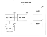
- FIG. 6 is a diagram showing an example of the internal configuration of the information processing apparatus 301 shown in FIG.
- the information processing apparatus 301 shown in FIG. 5 has a removal rate calculation unit 311, a concentration calculation unit 321, an output unit 330, a warning unit 340, and a database 351.
- FIG. 6 shows only the main components related to the present embodiment among the components included in the information processing apparatus 301 shown in FIG.
- Each of the output unit 330 and the warning unit 340 is the same as that in the first embodiment.
- FIG. 7 is a diagram showing an example of information showing past usage records stored in the database 351 shown in FIG.
- the database 351 shown in FIG. 6 is associated with the sequence, the yield, the functional material life, and the removal efficiency.
- the sequence is as described above.
- Yield is the ratio of water sampling to the constant yield of the series.
- the unit of yield is (%).
- a regenerative ion exchange device there is a design quantification for the amount of water collected that can exert the function of removing impurities as a device.
- the fixed yield is called constant yield.
- the regenerative ion exchange device whose water sampling amount has reached a constant yield can recover the function of removing impurities by going through the regeneration step.
- the functional material life indicates the age of the functional material filled in the series.
- the removal efficiency is the removal efficiency of impurities in the series.
- the unit of removal efficiency is (%).
- the yield “10”, the functional material life “5.0”, and the removal efficiency “80” are stored in association with each other. This shows the actual result that the removal efficiency was 80 (%) when 10 (%) of the constant yield of water was poured into the series A 5 years after the functional material was filled.
- constant yield and regeneration are repeated for the functional material for five years.
- the constant yield is generally 24 hours. Therefore, constant yield and regeneration are repeated about 1800 times in 5 years. The same applies to the functional material life described below.
- the yield "100”, the functional material life "1.5”, and the removal efficiency "85” are stored in association with each other. This shows the actual result that the removal efficiency was 85 (%) when 100 (%) of the constant yield of water was poured into the series B 1.5 years after the functional material was filled. ..
- the yield "50”, the functional material life "3.3”, and the removal efficiency "87” are stored in association with each other. This shows the actual result that the removal efficiency was 87 (%) when 50 (%) of the constant yield of water was poured into the series C 3.3 years after the functional material was filled. ..
- the yield "75”, the functional material life "0.5”, and the removal efficiency "90” are stored in association with each other.
- the number of correspondences stored in the database 351 is not limited to these. The larger the number of correspondences stored in the database 351 is, the more preferable. For example, all the actual data when the series A to D are used in the past are stored, and the same correspondence as the usage status of the series A to D currently used in the water treatment devices 100-1 to 100-5 is stored. It is preferable to be able to find.
- the removal rate calculation unit 311 determines the removal rate in each of the water treatment devices 100-1 to 100-5 based on the current usage state and the removal efficiency of the series constituting each of the water treatment devices 100-1 to 100-5. calculate.
- the removal efficiency used here is the ability to remove impurities stored in the database 351 from the past usage records of the series constituting each of the water treatment devices 100-1 to 100-5. This impurity is, for example, organic carbon.
- the water treatment apparatus 100-1 is composed of A to D series, the current yield of A series is 10 (%), and the filled functional material has passed for 5 years, and the current B series The functional material filled with a yield of 100 (%) has passed 1.5 years, and the functional material filled with a current yield of C series of 50 (%) has passed 3.3 years.
- the removal rate calculation unit 311 is the same as the state of each series stored in the database 351. Search for (closest) data.
- the removal rate calculation unit 311 acquires the removal rate (removal efficiency) associated with the retrieved data.
- the removal rate calculation unit 311 calculates the current removal rate of the water treatment apparatus 100-1 using the acquired removal efficiency. For example, when the value shown in FIG. 7 is stored in the database 351 the removal rate calculation unit 311 may average the removal efficiency of each of the A to D series. Further, the removal rate calculation unit 311 may calculate the total removal rate by multiplying each removal efficiency by weighting the constituent ratios of the A to D series.
- the removal rate calculation unit 311 may calculate the average value of the removal efficiency of each of the plurality of series used in one water treatment device and use it as the removal rate in the water treatment device. Further, the removal rate calculation unit 311 may search for the closest data from the data obtained from the usage record of the series being used and calculate the current removal rate of the water treatment apparatus.
- the concentration calculation unit 321 is the water arranged at the most downstream of the water treatment devices 100-1 to 100-5 based on the removal rates of the water treatment devices 100-1 to 100-5 calculated by the removal rate calculation unit 311. Calculate the concentration of impurities contained in the water supplied from the treatment device. At this time, the concentration of the impurities calculated by the concentration calculation unit 321 is arranged at the most downstream of the water treatment devices 100-1 to 100-5 when the current supply water is treated by the water treatment devices 100-1 to 100-5. It is the concentration of impurities contained in the water supplied from the water treatment equipment. In the connection form shown in FIG. 5, the water treatment device arranged at the most downstream is the water treatment device 100-5.
- the concentration calculation unit 321 determines the concentration of impurities contained in the water flowing into the water treatment device arranged at the uppermost stream and the removal rate of the water treatment devices 100-1 to 100-5 calculated by the removal rate calculation unit 311. Based on, the concentration of impurities contained in the water supplied from the water treatment device arranged at the most downstream is calculated. For example, the concentration of impurities contained in the water flowing into the water treatment device 100-1 arranged at the uppermost stream is 1000 (ppb), the removal rate of the water treatment device 100-1 is 80%, and the water treatment is performed. The removal rate of the device 100-2 is 75%, the removal rate of the water treatment device 100-3 is 70%, the removal rate of the water treatment device 100-4 is 65%, and the water treatment device 100-5 has a removal rate of 65%.
- the information processing device 301 has the current usage state of the series constituting the water treatment devices 100-1 to 100-5 and the past usage record of the series constituting the water treatment devices 100-1 to 100-5.
- the removal rate in each of the water treatment devices 100-1 to 100-5 is calculated based on the removal efficiency, which is the ability to remove impurities obtained from the water treatment apparatus 100-1 to 100-5.
- the information processing apparatus 301 is based on the calculated removal rates of the water treatment apparatus 100-1 to 100-5, and the impurities contained in the water supplied from the water treatment apparatus 100-5 arranged at the most downstream side are contained in the information processing apparatus 301. Calculate the concentration.
- the information processing device 301 calculates the removal rate based on the current status of the series constituting the water treatment devices 100-1 to 100-5. As a result, even if the treatment in each of the water treatment devices 100-1 to 100-5 takes time, the water quality of the water supplied to the use point can be grasped in advance.
- each component has been assigned to each function (process), but this allocation is not limited to the above. Further, the above-mentioned form is merely an example of the configuration of the constituent elements, and the present invention is not limited to this. Further, each embodiment may be combined.
- the information processing devices 300 and 301 may be provided on the cloud.
- the administrator who maintains / operates / manages the system may access the information processing devices 300 and 301 via the Internet using a communication terminal and receive input and output of information.
- the processing performed by each of the above-mentioned information processing devices 300 and 301 may be performed by logic circuits manufactured according to the purpose. Further, a computer program (hereinafter referred to as a program) in which the processing contents are described as a procedure is recorded on a recording medium readable by each of the information processing devices 300 and 301, and the program recorded on the recording medium is recorded on the information processing device. It may be read and executed by each of 300 and 301.
- the recording media that can be read by the information processing devices 300 and 301 are floppy (registered trademark) disc, magneto-optical disc, DVD (Digital Versaille Disc), CD (Compact Disc), Blu-ray (registered trademark) Disc, and the like.
Landscapes
- Engineering & Computer Science (AREA)
- Business, Economics & Management (AREA)
- Economics (AREA)
- Water Supply & Treatment (AREA)
- Life Sciences & Earth Sciences (AREA)
- Chemical & Material Sciences (AREA)
- Human Resources & Organizations (AREA)
- Strategic Management (AREA)
- Organic Chemistry (AREA)
- Hydrology & Water Resources (AREA)
- Environmental & Geological Engineering (AREA)
- Physics & Mathematics (AREA)
- General Physics & Mathematics (AREA)
- Health & Medical Sciences (AREA)
- Tourism & Hospitality (AREA)
- General Business, Economics & Management (AREA)
- Theoretical Computer Science (AREA)
- Marketing (AREA)
- General Health & Medical Sciences (AREA)
- Entrepreneurship & Innovation (AREA)
- Quality & Reliability (AREA)
- Operations Research (AREA)
- Game Theory and Decision Science (AREA)
- Development Economics (AREA)
- Primary Health Care (AREA)
- Public Health (AREA)
- Physical Water Treatments (AREA)
- Management, Administration, Business Operations System, And Electronic Commerce (AREA)
- Water Treatment By Sorption (AREA)
- Separation Using Semi-Permeable Membranes (AREA)
- Emergency Management (AREA)
- Food Science & Technology (AREA)
- Medicinal Chemistry (AREA)
- Analytical Chemistry (AREA)
- Biochemistry (AREA)
- Immunology (AREA)
- Pathology (AREA)
Abstract
Description
前記情報処理装置は、
前記水処理装置における前記不純物を除去する除去率に基づいて、現在の供給水が前記水処理装置で処理された場合における前記水処理装置から供給される水に含まれる前記不純物の濃度の予測値を算出する濃度算出部を有する水処理システムである。
供給される水から不純物を除去する水処理装置における前記不純物を除去する除去率に基づいて、現在の供給水が前記水処理装置で処理された場合における前記水処理装置から供給される水に含まれる前記不純物の濃度の予測値を算出する手順を実行させるためのプログラムである。
(第1の実施の形態)
900(TOC値)×(1-0.7(1分前の除去率))=270
として、水処理装置100-1から供給される水のTOC予測値を算出する。続いて、濃度算出部320は、
270(TOC予測値)×(1-0.2(1分前の除去率))=216
として、水処理装置100-2から供給される水のTOC予測値を算出する。続いて、濃度算出部320は、
216(TOC予測値)×(1-0.75(1分前の除去率))=54
として、水処理装置100-3から供給される水のTOC予測値を算出する。続いて、濃度算出部320は、
54(TOC予測値)×(1-0.93(1分前の除去率))=3.8
として、水処理装置100-4から供給される水のTOC予測値を算出する。続いて、濃度算出部320は、
3.8(TOC予測値)×(1-0.75(1分前の除去率))=0.95
として、水処理装置100-5から供給される水のTOC予測値を算出する。このようにして、濃度算出部320は、最下流に接続された水処理装置100-5から供給される水に含まれるTOC(不純物)の濃度をTOC予測値として算出する。
・原水槽1001において再生水を受け入れない。
・尿素を除去するための尿素分解剤の注入量を増加させる。
・ろ過水槽1003において回収水を受け入れない。
・活性炭塔1004内の系列を変更する。
・K塔1005内の系列を変更する。
・D塔1006に空気の代わりに高純度窒素を注入する。
・A塔1007内の系列を変更する。
・RO装置1009内の系列を変更する。
・RO装置1009の流量を増加させる。
・UV酸化装置1011に具備されたランプの点灯本数を増加させる。
・UV酸化装置1014に具備されたランプの点灯本数を増加させる。
(第2の実施の形態)
1000×(1-0.8)×(1-0.75)×(1-0.7)×(1-0.65)×(1-0.6)=2(ppb)
が最下流に配置された水処理装置100-5から供給される水に含まれる不純物の濃度となる。なお、この数値は説明の便宜上の値であって、通常のシステムで実際に使用されるものではない。
Claims (20)
- 供給される水から不純物を除去する水処理装置と、情報処理装置とを有し、
前記情報処理装置は、
前記水処理装置における前記不純物を除去する除去率に基づいて、現在の供給水が前記水処理装置で処理された場合における前記水処理装置から供給される水に含まれる前記不純物の濃度の予測値を算出する濃度算出部を有する水処理システム。 - 請求項1に記載の水処理システムにおいて、
前記除去率を算出する除去率算出部と、
前記除去率算出部が算出した前記水処理装置の前記除去率を記憶する記憶部と、を有し、
前記濃度算出部は、前記記憶部に記憶された前記除去率に基づいて、前記不純物の濃度の予測値を算出する水処理システム。 - 請求項2に記載の水処理システムにおいて、
前記水処理装置に供給される水および前記水処理装置から供給される水に含まれる前記不純物の濃度を測定する濃度測定部を有し、
前記除去率算出部は、前記濃度測定部が測定した濃度に基づいて、前記水処理装置における前記除去率を算出する水処理システム。 - 請求項3に記載の水処理システムにおいて、
前記濃度測定部は、前記水処理装置から供給される水に含まれる全有機炭素の濃度と尿素の濃度とを測定し、
前記除去率算出部は、前記濃度測定部が測定した前記全有機炭素の濃度と前記尿素の濃度とに基づいて、前記水処理装置における前記除去率を算出する水処理システム。 - 請求項2に記載の水処理システムにおいて、
前記除去率算出部は、前記水処理装置の現在の使用状態と、過去の使用実績とに基づいて、該水処理装置の現在の前記除去率を算出する水処理システム。 - 請求項1から5のいずれか1項に記載の水処理システムにおいて、
前記情報処理装置は、前記濃度算出部が算出した濃度を示す情報を出力する出力部を有する水処理システム。 - 請求項1から6のいずれか1項に記載の水処理システムにおいて、
前記情報処理装置は、前記濃度算出部が算出した濃度が所定の閾値を超えた場合、所定の警告を出力する警告部を有する水処理システム。 - 請求項7に記載の水処理システムにおいて、
前記警告部は、前記濃度算出部が算出した濃度が所定の閾値を超えた場合、該濃度を下げるための処理を行うための信号を出力する水処理システム。 - 供給される水から不純物を除去する水処理装置における前記不純物を除去する除去率に基づいて、現在の供給水が前記水処理装置で処理された場合における前記水処理装置から供給される水に含まれる前記不純物の濃度の予測値を算出する濃度算出部を有する情報処理装置。
- 請求項9に記載の情報処理装置において、
前記除去率を算出する除去率算出部と、
前記除去率算出部が算出した前記水処理装置の前記除去率を記憶する記憶部と、を有し、
前記濃度算出部は、前記記憶部に記憶された前記除去率に基づいて、前記不純物の濃度の予測値を算出する情報処理装置。 - 請求項10に記載の情報処理装置において、
前記除去率算出部は、前記水処理装置に供給される水および前記水処理装置から供給される水に含まれる前記不純物の濃度に基づいて、前記水処理装置における前記除去率を算出する情報処理装置。 - 請求項10に記載の情報処理装置において、
前記除去率算出部は、前記水処理装置の現在の使用状態と、過去の使用実績とに基づいて、該水処理装置の現在の前記除去率を算出する情報処理装置。 - 供給される水から不純物を除去する水処理装置における前記不純物を除去する除去率に基づいて、現在の供給水が前記水処理装置で処理された場合における前記水処理装置から供給される水に含まれる前記不純物の濃度の予測値を算出する処理を行う情報処理方法。
- 請求項13に記載の情報処理方法において、
前記除去率を算出する処理と、
前記算出した前記水処理装置の前記除去率を記憶部に記憶させる処理と、
前記記憶部に記憶された前記除去率に基づいて、前記不純物の濃度の予測値を算出する処理とを行う情報処理方法。 - 請求項13に記載の情報処理方法において、
前記水処理装置に供給される水および前記水処理装置から供給される水に含まれる前記不純物の濃度を測定する処理と、
前記測定した濃度に基づいて、前記水処理装置における前記除去率を算出する処理とを行う情報処理方法。 - 請求項13に記載の情報処理方法において、
前記水処理装置の現在の使用状態と、過去の使用実績とに基づいて、該水処理装置における前記除去率を算出する処理を行う情報処理方法。 - コンピュータに、
供給される水から不純物を除去する水処理装置における前記不純物を除去する除去率に基づいて、現在の供給水が前記水処理装置で処理された場合における前記水処理装置から供給される水に含まれる前記不純物の濃度の予測値を算出する手順を実行させるためのプログラム。 - 請求項17に記載のプログラムにおいて、
前記除去率を算出する手順と、
前記算出した前記水処理装置の前記除去率を記憶部に記憶させる手順と、
前記記憶部に記憶された前記除去率に基づいて、前記不純物の濃度の予測値を算出する手順とを実行させるためのプログラム。 - 請求項17に記載のプログラムにおいて、
前記水処理装置に供給される水および前記水処理装置から供給される水に含まれる前記不純物の濃度を測定する手順と、
前記測定した濃度に基づいて、前記水処理装置における前記除去率を算出する手順とを実行させるためのプログラム。 - 請求項17に記載のプログラムにおいて、
前記水処理装置の現在の使用状態と、過去の使用実績とに基づいて、該水処理装置における前記除去率を算出する手順を実行させるためのプログラム。
Priority Applications (3)
| Application Number | Priority Date | Filing Date | Title |
|---|---|---|---|
| CN202180050170.9A CN115867514A (zh) | 2020-09-09 | 2021-08-20 | 水处理系统、信息处理装置、信息处理方法以及程序 |
| US18/024,844 US20230312372A1 (en) | 2020-09-09 | 2021-08-20 | Water treatment system, information processing device, information processing method, and program |
| KR1020237005036A KR20230038265A (ko) | 2020-09-09 | 2021-08-20 | 수처리 시스템, 정보처리장치, 정보처리방법 및 프로그램 |
Applications Claiming Priority (2)
| Application Number | Priority Date | Filing Date | Title |
|---|---|---|---|
| JP2020-151402 | 2020-09-09 | ||
| JP2020151402A JP7064541B2 (ja) | 2020-09-09 | 2020-09-09 | 水処理システム、情報処理装置、情報処理方法およびプログラム |
Publications (1)
| Publication Number | Publication Date |
|---|---|
| WO2022054537A1 true WO2022054537A1 (ja) | 2022-03-17 |
Family
ID=80631572
Family Applications (1)
| Application Number | Title | Priority Date | Filing Date |
|---|---|---|---|
| PCT/JP2021/030530 Ceased WO2022054537A1 (ja) | 2020-09-09 | 2021-08-20 | 水処理システム、情報処理装置、情報処理方法およびプログラム |
Country Status (6)
| Country | Link |
|---|---|
| US (1) | US20230312372A1 (ja) |
| JP (1) | JP7064541B2 (ja) |
| KR (1) | KR20230038265A (ja) |
| CN (1) | CN115867514A (ja) |
| TW (1) | TWI883253B (ja) |
| WO (1) | WO2022054537A1 (ja) |
Families Citing this family (2)
| Publication number | Priority date | Publication date | Assignee | Title |
|---|---|---|---|---|
| TWM636111U (zh) | 2021-09-02 | 2023-01-01 | 財團法人工業技術研究院 | 尿素檢測裝置 |
| JP2025135296A (ja) * | 2024-03-05 | 2025-09-18 | オルガノ株式会社 | 液体処理システム、情報処理装置および情報処理方法 |
Citations (1)
| Publication number | Priority date | Publication date | Assignee | Title |
|---|---|---|---|---|
| JP2012526657A (ja) * | 2009-05-14 | 2012-11-01 | オムニ ウォーター ソリューションズ, エルエルシー | 内蔵型携帯用多モード水処理システムおよび方法 |
Family Cites Families (4)
| Publication number | Priority date | Publication date | Assignee | Title |
|---|---|---|---|---|
| JPH06134457A (ja) | 1992-10-28 | 1994-05-17 | Hitachi Plant Eng & Constr Co Ltd | 超純水の製造システム及び製造方法 |
| JP6978353B2 (ja) * | 2018-03-13 | 2021-12-08 | オルガノ株式会社 | 水処理管理装置及び水質監視方法 |
| JP7243039B2 (ja) * | 2018-04-27 | 2023-03-22 | 栗田工業株式会社 | 尿素監視装置及び純水製造装置 |
| CN111204849A (zh) * | 2020-01-13 | 2020-05-29 | 湖南航天电团网络科技有限公司 | 污水应急处理方法、装置、计算机设备和存储介质 |
-
2020
- 2020-09-09 JP JP2020151402A patent/JP7064541B2/ja active Active
-
2021
- 2021-08-20 CN CN202180050170.9A patent/CN115867514A/zh active Pending
- 2021-08-20 US US18/024,844 patent/US20230312372A1/en active Pending
- 2021-08-20 KR KR1020237005036A patent/KR20230038265A/ko not_active Ceased
- 2021-08-20 WO PCT/JP2021/030530 patent/WO2022054537A1/ja not_active Ceased
- 2021-08-27 TW TW110131767A patent/TWI883253B/zh active
Patent Citations (1)
| Publication number | Priority date | Publication date | Assignee | Title |
|---|---|---|---|---|
| JP2012526657A (ja) * | 2009-05-14 | 2012-11-01 | オムニ ウォーター ソリューションズ, エルエルシー | 内蔵型携帯用多モード水処理システムおよび方法 |
Also Published As
| Publication number | Publication date |
|---|---|
| JP7064541B2 (ja) | 2022-05-10 |
| KR20230038265A (ko) | 2023-03-17 |
| TW202212270A (zh) | 2022-04-01 |
| US20230312372A1 (en) | 2023-10-05 |
| TWI883253B (zh) | 2025-05-11 |
| JP2022045685A (ja) | 2022-03-22 |
| CN115867514A (zh) | 2023-03-28 |
Similar Documents
| Publication | Publication Date | Title |
|---|---|---|
| JP7064541B2 (ja) | 水処理システム、情報処理装置、情報処理方法およびプログラム | |
| JP3200301B2 (ja) | 純水又は超純水の製造方法及び製造装置 | |
| JP4935395B2 (ja) | 膜分離装置被処理水の評価方法、水処理方法及び水処理装置 | |
| JP5081690B2 (ja) | 超純水の製造方法 | |
| KR20140042784A (ko) | 초순수 제공 방법 및 시스템 | |
| JP6304089B2 (ja) | アルゴンガスの精製方法及びアルゴンガスの回収精製装置 | |
| CN109293037B (zh) | 一种净水设备滤芯寿命的判定及管理方法 | |
| JP7563959B2 (ja) | 超純水製造システム及び超純水製造方法 | |
| JP2002210494A (ja) | 超純水製造装置 | |
| JP2010216943A (ja) | 溶存窒素濃度の測定方法及び溶存窒素濃度の測定装置 | |
| JPH09122690A (ja) | 有機態窒素の分解方法及び水処理装置 | |
| JP6022194B2 (ja) | Toc低減装置およびtoc低減方法 | |
| JP2011162655A (ja) | 作動油再生装置および作動油再生方法 | |
| JP2950621B2 (ja) | 超純水の製造方法 | |
| JP7161280B2 (ja) | Ro膜の洗浄管理方法 | |
| TW202214527A (zh) | 水處理系統、控制裝置、水處理方法及程式 | |
| WO2025187380A1 (ja) | 液体処理システム、情報処理装置および情報処理方法 | |
| JP3231606B2 (ja) | 超純水製造装置 | |
| TW202603918A (zh) | 資訊處理裝置、判斷方法及水處理系統 | |
| JPH05138196A (ja) | 高純度超純水製造装置と水質制御法 | |
| JPH07284614A (ja) | 流体の濾過方法 | |
| TW202222704A (zh) | 水處理系統及水處理方法 | |
| JPH0824852A (ja) | 純水または超純水の製造装置 | |
| WO2026038433A1 (ja) | 水処理設備、制御装置、運転方法およびプログラム | |
| JP2022029254A (ja) | 情報処理システム、情報処理方法およびプログラム |
Legal Events
| Date | Code | Title | Description |
|---|---|---|---|
| 121 | Ep: the epo has been informed by wipo that ep was designated in this application |
Ref document number: 21866497 Country of ref document: EP Kind code of ref document: A1 |
|
| ENP | Entry into the national phase |
Ref document number: 20237005036 Country of ref document: KR Kind code of ref document: A |
|
| NENP | Non-entry into the national phase |
Ref country code: DE |
|
| 122 | Ep: pct application non-entry in european phase |
Ref document number: 21866497 Country of ref document: EP Kind code of ref document: A1 |
|
| WWR | Wipo information: refused in national office |
Ref document number: 1020237005036 Country of ref document: KR |