WO2022050190A1 - Production method for optical fiber base material, and optical fiber base material - Google Patents
Production method for optical fiber base material, and optical fiber base material Download PDFInfo
- Publication number
- WO2022050190A1 WO2022050190A1 PCT/JP2021/031564 JP2021031564W WO2022050190A1 WO 2022050190 A1 WO2022050190 A1 WO 2022050190A1 JP 2021031564 W JP2021031564 W JP 2021031564W WO 2022050190 A1 WO2022050190 A1 WO 2022050190A1
- Authority
- WO
- WIPO (PCT)
- Prior art keywords
- optical fiber
- base material
- fiber base
- glass
- core portion
- Prior art date
Links
- 239000013307 optical fiber Substances 0.000 title claims abstract description 66
- 239000000463 material Substances 0.000 title claims abstract description 58
- 238000004519 manufacturing process Methods 0.000 title claims abstract description 33
- 239000011521 glass Substances 0.000 claims abstract description 177
- 239000002585 base Substances 0.000 claims abstract description 56
- VYPSYNLAJGMNEJ-UHFFFAOYSA-N Silicium dioxide Chemical compound O=[Si]=O VYPSYNLAJGMNEJ-UHFFFAOYSA-N 0.000 claims abstract description 40
- 238000000034 method Methods 0.000 claims abstract description 37
- 229910052783 alkali metal Inorganic materials 0.000 claims abstract description 12
- 229910052784 alkaline earth metal Inorganic materials 0.000 claims abstract description 12
- 150000001340 alkali metals Chemical class 0.000 claims abstract description 11
- 150000001342 alkaline earth metals Chemical class 0.000 claims abstract description 11
- 239000000460 chlorine Substances 0.000 claims description 48
- ZAMOUSCENKQFHK-UHFFFAOYSA-N Chlorine atom Chemical compound [Cl] ZAMOUSCENKQFHK-UHFFFAOYSA-N 0.000 claims description 47
- 229910052801 chlorine Inorganic materials 0.000 claims description 47
- 230000002093 peripheral effect Effects 0.000 claims description 21
- 230000010354 integration Effects 0.000 claims description 20
- 239000011737 fluorine Substances 0.000 claims description 18
- 229910052731 fluorine Inorganic materials 0.000 claims description 18
- 239000000377 silicon dioxide Substances 0.000 claims description 17
- 238000005530 etching Methods 0.000 claims description 11
- ZLMJMSJWJFRBEC-UHFFFAOYSA-N Potassium Chemical compound [K] ZLMJMSJWJFRBEC-UHFFFAOYSA-N 0.000 claims description 5
- 229910052700 potassium Inorganic materials 0.000 claims description 5
- 239000011591 potassium Substances 0.000 claims description 5
- OYPRJOBELJOOCE-UHFFFAOYSA-N Calcium Chemical compound [Ca] OYPRJOBELJOOCE-UHFFFAOYSA-N 0.000 claims description 3
- DGAQECJNVWCQMB-PUAWFVPOSA-M Ilexoside XXIX Chemical compound C[C@@H]1CC[C@@]2(CC[C@@]3(C(=CC[C@H]4[C@]3(CC[C@@H]5[C@@]4(CC[C@@H](C5(C)C)OS(=O)(=O)[O-])C)C)[C@@H]2[C@]1(C)O)C)C(=O)O[C@H]6[C@@H]([C@H]([C@@H]([C@H](O6)CO)O)O)O.[Na+] DGAQECJNVWCQMB-PUAWFVPOSA-M 0.000 claims description 3
- 229910052792 caesium Inorganic materials 0.000 claims description 3
- TVFDJXOCXUVLDH-UHFFFAOYSA-N caesium atom Chemical compound [Cs] TVFDJXOCXUVLDH-UHFFFAOYSA-N 0.000 claims description 3
- 229910052791 calcium Inorganic materials 0.000 claims description 3
- 239000011575 calcium Substances 0.000 claims description 3
- 229910052701 rubidium Inorganic materials 0.000 claims description 3
- IGLNJRXAVVLDKE-UHFFFAOYSA-N rubidium atom Chemical compound [Rb] IGLNJRXAVVLDKE-UHFFFAOYSA-N 0.000 claims description 3
- 229910052708 sodium Inorganic materials 0.000 claims description 3
- 239000011734 sodium Substances 0.000 claims description 3
- PXGOKWXKJXAPGV-UHFFFAOYSA-N Fluorine Chemical compound FF PXGOKWXKJXAPGV-UHFFFAOYSA-N 0.000 claims 2
- 239000003513 alkali Substances 0.000 abstract description 6
- 238000005253 cladding Methods 0.000 abstract 1
- YCKRFDGAMUMZLT-UHFFFAOYSA-N Fluorine atom Chemical compound [F] YCKRFDGAMUMZLT-UHFFFAOYSA-N 0.000 description 16
- 230000005540 biological transmission Effects 0.000 description 15
- 230000002159 abnormal effect Effects 0.000 description 14
- 230000007547 defect Effects 0.000 description 7
- 238000002360 preparation method Methods 0.000 description 7
- 230000009467 reduction Effects 0.000 description 7
- 238000000227 grinding Methods 0.000 description 6
- IOLCXVTUBQKXJR-UHFFFAOYSA-M potassium bromide Chemical compound [K+].[Br-] IOLCXVTUBQKXJR-UHFFFAOYSA-M 0.000 description 6
- 230000008569 process Effects 0.000 description 6
- 239000002994 raw material Substances 0.000 description 6
- 238000009826 distribution Methods 0.000 description 5
- 239000002019 doping agent Substances 0.000 description 5
- 238000010438 heat treatment Methods 0.000 description 5
- 239000012535 impurity Substances 0.000 description 4
- NLKNQRATVPKPDG-UHFFFAOYSA-M potassium iodide Chemical compound [K+].[I-] NLKNQRATVPKPDG-UHFFFAOYSA-M 0.000 description 4
- JAAGVIUFBAHDMA-UHFFFAOYSA-M rubidium bromide Chemical compound [Br-].[Rb+] JAAGVIUFBAHDMA-UHFFFAOYSA-M 0.000 description 4
- WFUBYPSJBBQSOU-UHFFFAOYSA-M rubidium iodide Chemical compound [Rb+].[I-] WFUBYPSJBBQSOU-UHFFFAOYSA-M 0.000 description 4
- 235000012239 silicon dioxide Nutrition 0.000 description 4
- QVGXLLKOCUKJST-UHFFFAOYSA-N atomic oxygen Chemical compound [O] QVGXLLKOCUKJST-UHFFFAOYSA-N 0.000 description 3
- 239000007789 gas Substances 0.000 description 3
- 239000001301 oxygen Substances 0.000 description 3
- 229910052760 oxygen Inorganic materials 0.000 description 3
- 230000005856 abnormality Effects 0.000 description 2
- 239000010953 base metal Substances 0.000 description 2
- 239000012159 carrier gas Substances 0.000 description 2
- 238000002425 crystallisation Methods 0.000 description 2
- 230000008025 crystallization Effects 0.000 description 2
- 238000005259 measurement Methods 0.000 description 2
- 230000004048 modification Effects 0.000 description 2
- 238000012986 modification Methods 0.000 description 2
- 239000000523 sample Substances 0.000 description 2
- 230000001133 acceleration Effects 0.000 description 1
- 230000015572 biosynthetic process Effects 0.000 description 1
- 150000001875 compounds Chemical class 0.000 description 1
- 239000013078 crystal Substances 0.000 description 1
- 230000002950 deficient Effects 0.000 description 1
- 230000008021 deposition Effects 0.000 description 1
- 238000009792 diffusion process Methods 0.000 description 1
- 230000000694 effects Effects 0.000 description 1
- 230000006698 induction Effects 0.000 description 1
- 239000000203 mixture Substances 0.000 description 1
- 230000003287 optical effect Effects 0.000 description 1
- 239000012071 phase Substances 0.000 description 1
- 239000010453 quartz Substances 0.000 description 1
- 230000008707 rearrangement Effects 0.000 description 1
- 238000011946 reduction process Methods 0.000 description 1
- 230000008439 repair process Effects 0.000 description 1
- 230000007847 structural defect Effects 0.000 description 1
- 239000000126 substance Substances 0.000 description 1
- 230000002194 synthesizing effect Effects 0.000 description 1
- 238000007740 vapor deposition Methods 0.000 description 1
- 239000012808 vapor phase Substances 0.000 description 1
- XLYOFNOQVPJJNP-UHFFFAOYSA-N water Substances O XLYOFNOQVPJJNP-UHFFFAOYSA-N 0.000 description 1
Images

Classifications
-
- C—CHEMISTRY; METALLURGY
- C03—GLASS; MINERAL OR SLAG WOOL
- C03B—MANUFACTURE, SHAPING, OR SUPPLEMENTARY PROCESSES
- C03B37/00—Manufacture or treatment of flakes, fibres, or filaments from softened glass, minerals, or slags
- C03B37/01—Manufacture of glass fibres or filaments
- C03B37/012—Manufacture of preforms for drawing fibres or filaments
- C03B37/01205—Manufacture of preforms for drawing fibres or filaments starting from tubes, rods, fibres or filaments
- C03B37/01211—Manufacture of preforms for drawing fibres or filaments starting from tubes, rods, fibres or filaments by inserting one or more rods or tubes into a tube
-
- C—CHEMISTRY; METALLURGY
- C03—GLASS; MINERAL OR SLAG WOOL
- C03B—MANUFACTURE, SHAPING, OR SUPPLEMENTARY PROCESSES
- C03B37/00—Manufacture or treatment of flakes, fibres, or filaments from softened glass, minerals, or slags
- C03B37/01—Manufacture of glass fibres or filaments
- C03B37/012—Manufacture of preforms for drawing fibres or filaments
- C03B37/01205—Manufacture of preforms for drawing fibres or filaments starting from tubes, rods, fibres or filaments
- C03B37/01225—Means for changing or stabilising the shape, e.g. diameter, of tubes or rods in general, e.g. collapsing
- C03B37/01228—Removal of preform material
-
- C—CHEMISTRY; METALLURGY
- C03—GLASS; MINERAL OR SLAG WOOL
- C03B—MANUFACTURE, SHAPING, OR SUPPLEMENTARY PROCESSES
- C03B37/00—Manufacture or treatment of flakes, fibres, or filaments from softened glass, minerals, or slags
- C03B37/01—Manufacture of glass fibres or filaments
- C03B37/012—Manufacture of preforms for drawing fibres or filaments
- C03B37/01205—Manufacture of preforms for drawing fibres or filaments starting from tubes, rods, fibres or filaments
- C03B37/01225—Means for changing or stabilising the shape, e.g. diameter, of tubes or rods in general, e.g. collapsing
- C03B37/0124—Means for reducing the diameter of rods or tubes by drawing, e.g. for preform draw-down
-
- C—CHEMISTRY; METALLURGY
- C03—GLASS; MINERAL OR SLAG WOOL
- C03B—MANUFACTURE, SHAPING, OR SUPPLEMENTARY PROCESSES
- C03B37/00—Manufacture or treatment of flakes, fibres, or filaments from softened glass, minerals, or slags
- C03B37/01—Manufacture of glass fibres or filaments
- C03B37/012—Manufacture of preforms for drawing fibres or filaments
- C03B37/014—Manufacture of preforms for drawing fibres or filaments made entirely or partially by chemical means, e.g. vapour phase deposition of bulk porous glass either by outside vapour deposition [OVD], or by outside vapour phase oxidation [OVPO] or by vapour axial deposition [VAD]
- C03B37/018—Manufacture of preforms for drawing fibres or filaments made entirely or partially by chemical means, e.g. vapour phase deposition of bulk porous glass either by outside vapour deposition [OVD], or by outside vapour phase oxidation [OVPO] or by vapour axial deposition [VAD] by glass deposition on a glass substrate, e.g. by inside-, modified-, plasma-, or plasma modified- chemical vapour deposition [ICVD, MCVD, PCVD, PMCVD], i.e. by thin layer coating on the inside or outside of a glass tube or on a glass rod
- C03B37/01861—Means for changing or stabilising the diameter or form of tubes or rods
-
- C—CHEMISTRY; METALLURGY
- C03—GLASS; MINERAL OR SLAG WOOL
- C03B—MANUFACTURE, SHAPING, OR SUPPLEMENTARY PROCESSES
- C03B2201/00—Type of glass produced
- C03B2201/06—Doped silica-based glasses
- C03B2201/08—Doped silica-based glasses doped with boron or fluorine or other refractive index decreasing dopant
- C03B2201/12—Doped silica-based glasses doped with boron or fluorine or other refractive index decreasing dopant doped with fluorine
-
- C—CHEMISTRY; METALLURGY
- C03—GLASS; MINERAL OR SLAG WOOL
- C03B—MANUFACTURE, SHAPING, OR SUPPLEMENTARY PROCESSES
- C03B2201/00—Type of glass produced
- C03B2201/06—Doped silica-based glasses
- C03B2201/20—Doped silica-based glasses doped with non-metals other than boron or fluorine
-
- C—CHEMISTRY; METALLURGY
- C03—GLASS; MINERAL OR SLAG WOOL
- C03B—MANUFACTURE, SHAPING, OR SUPPLEMENTARY PROCESSES
- C03B2201/00—Type of glass produced
- C03B2201/06—Doped silica-based glasses
- C03B2201/30—Doped silica-based glasses doped with metals, e.g. Ga, Sn, Sb, Pb or Bi
- C03B2201/50—Doped silica-based glasses doped with metals, e.g. Ga, Sn, Sb, Pb or Bi doped with alkali metals
-
- C—CHEMISTRY; METALLURGY
- C03—GLASS; MINERAL OR SLAG WOOL
- C03B—MANUFACTURE, SHAPING, OR SUPPLEMENTARY PROCESSES
- C03B2203/00—Fibre product details, e.g. structure, shape
- C03B2203/10—Internal structure or shape details
- C03B2203/22—Radial profile of refractive index, composition or softening point
-
- C—CHEMISTRY; METALLURGY
- C03—GLASS; MINERAL OR SLAG WOOL
- C03B—MANUFACTURE, SHAPING, OR SUPPLEMENTARY PROCESSES
- C03B37/00—Manufacture or treatment of flakes, fibres, or filaments from softened glass, minerals, or slags
- C03B37/01—Manufacture of glass fibres or filaments
- C03B37/012—Manufacture of preforms for drawing fibres or filaments
- C03B37/014—Manufacture of preforms for drawing fibres or filaments made entirely or partially by chemical means, e.g. vapour phase deposition of bulk porous glass either by outside vapour deposition [OVD], or by outside vapour phase oxidation [OVPO] or by vapour axial deposition [VAD]
- C03B37/018—Manufacture of preforms for drawing fibres or filaments made entirely or partially by chemical means, e.g. vapour phase deposition of bulk porous glass either by outside vapour deposition [OVD], or by outside vapour phase oxidation [OVPO] or by vapour axial deposition [VAD] by glass deposition on a glass substrate, e.g. by inside-, modified-, plasma-, or plasma modified- chemical vapour deposition [ICVD, MCVD, PCVD, PMCVD], i.e. by thin layer coating on the inside or outside of a glass tube or on a glass rod
- C03B37/01807—Reactant delivery systems, e.g. reactant deposition burners
-
- Y—GENERAL TAGGING OF NEW TECHNOLOGICAL DEVELOPMENTS; GENERAL TAGGING OF CROSS-SECTIONAL TECHNOLOGIES SPANNING OVER SEVERAL SECTIONS OF THE IPC; TECHNICAL SUBJECTS COVERED BY FORMER USPC CROSS-REFERENCE ART COLLECTIONS [XRACs] AND DIGESTS
- Y02—TECHNOLOGIES OR APPLICATIONS FOR MITIGATION OR ADAPTATION AGAINST CLIMATE CHANGE
- Y02P—CLIMATE CHANGE MITIGATION TECHNOLOGIES IN THE PRODUCTION OR PROCESSING OF GOODS
- Y02P40/00—Technologies relating to the processing of minerals
- Y02P40/50—Glass production, e.g. reusing waste heat during processing or shaping
- Y02P40/57—Improving the yield, e-g- reduction of reject rates
Definitions
- This disclosure relates to a method for manufacturing an optical fiber base material and an optical fiber base material.
- the core made of silica-based glass contains an alkali metal element or an alkaline earth metal element, the viscosity of the core is reduced when the optical fiber base material is drawn to manufacture the optical fiber, and the glass is regenerated. The sequence is promoted. Therefore, the transmission loss due to the ray scattering of the optical fiber is reduced. As a result, the transmission loss can be reduced.
- Patent Document 1 Patent Document 2, and Patent Document 3 describe a method of adding an alkali metal element or an alkaline earth metal element to the core portion of an optical fiber base material by a diffusion method.
- the method for producing an optical fiber base material of the present disclosure is a method for producing an optical fiber base material made of silica-based glass, which has a core portion and a refractive index lower than the refractive index of the core portion. Includes forming a clad portion that surrounds the core portion.
- an alkaline element group composed of an alkali metal element and an alkaline earth metal element is added to the inner surface of a glass pipe made of silica-based glass, and after the addition, the glass pipe and the glass pipe are formed. It includes integrating with a glass rod arranged in a glass pipe to form an integrated rod.
- the optical fiber base material of the present disclosure is an optical fiber base material made of silica-based glass, and has a core portion containing an alkali element group consisting of an alkali metal element and an alkaline earth metal element, and has a lower refractive index than the core portion. It has a refractive index and includes a clad portion that surrounds the core portion.
- the core portion includes a region having a chlorine mass fraction lower than the chlorine mass fraction on the central axis of the core portion.
- the mass fraction of the alkaline element group in the core portion has the maximum value other than the central axis.
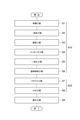
- FIG. 1 is a flowchart showing a method for manufacturing an optical fiber according to an embodiment.
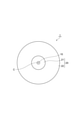
- FIG. 2 is a cross-sectional view of the optical fiber base material according to the embodiment.
- FIG. 3 is a graph showing the alkali element concentration distribution and the chlorine concentration distribution in the core portion.
- Patent Document 1 Patent Document 2, and Patent Document 3
- an alkali metal element or an alkaline earth metal element is added to the inner surface of a glass pipe, and the glass pipe is reduced in diameter, etched, and then solidified.
- a glass body that becomes the core portion of the optical fiber base material is manufactured.
- the inside of the glass pipe is hollow, the volume (glass amount) of the glass pipe is smaller than that of a glass cylinder having the same outer diameter. Therefore, productivity is low.
- An object of the present disclosure is to provide a method for manufacturing an optical fiber base material capable of improving productivity while suppressing transmission loss.
- the method for manufacturing an optical fiber base material according to an embodiment of the present disclosure is a method for manufacturing an optical fiber base material made of silica-based glass, in which a core portion is formed and a refraction lower than the refractive index of the core portion is performed. It has a rate and includes forming a clad portion that surrounds the core portion.
- an alkaline element group composed of an alkali metal element and an alkaline earth metal element is added to the inner surface of a glass pipe made of silica-based glass, and after the addition, the glass pipe and the glass pipe are formed. It includes integrating with a glass rod arranged in a glass pipe to form an integrated rod.
- an alkaline element group is added to the inner surface of a glass pipe, so that transmission loss can be reduced. Further, since the glass pipe and the glass rod arranged in the glass pipe are integrated, the productivity can be improved as compared with the case where the glass pipe is solidified to form a glass body to be a core portion.
- Forming the core portion may further include reducing the diameter of the glass pipe between adding and integrating. If the diameter of the glass rod used is significantly different from the hole diameter of the glass pipe, a non-circle is likely to occur in the core portion after integration. In this case, the diameter reduction allows the hole diameter of the glass pipe to be close to the diameter of the glass lot, so that non-circle formation in the core portion is suppressed.
- Forming the core portion may further include etching the inner surface of the glass pipe between adding and integrating. In this case, impurities added to the inner surface of the glass pipe together with the alkaline element group can be removed.
- the average value of the mass fraction of chlorine in the glass rod may be 20 ppm or more and 2000 ppm or less.
- the average value of the mass fraction of chlorine in the glass pipe may be 20 ppm or more and 2000 ppm or less.
- the average value of the mass fraction of fluorine in the glass rod may be 200 ppm or more and 5000 ppm or less.
- the abnormal portion is a glass crystal formed by, for example, a foreign substance or a compound of an alkaline element group and chlorine or fluorine, and refers to a portion that becomes a defective portion when it becomes an optical fiber later.
- the average value of the mass fraction of fluorine in the glass pipe may be 200 ppm or more and 5000 ppm or less. In this case, it is possible to suppress the abnormal number of copies of the optical fiber base material.
- the glass rod includes an outer peripheral surface of the glass rod and has an outer peripheral portion having a thickness of 0.5 mm, and the average value of the mass fraction of chlorine in the outer peripheral portion is the average value of the mass fraction of chlorine in the entire glass rod. May be lower than. In this case, it is possible to suppress the abnormal number of copies of the optical fiber base material.
- the average value of the mass fraction of chlorine in the outer peripheral portion may be 20 ppm or more and 2000 ppm or less. In this case, it is possible to suppress the abnormal number of copies of the optical fiber base material.
- Forming the core portion may further include imparting a glass layer having a higher refractive index than the clad portion around the integrated rod.
- the degree of freedom in designing optical characteristics such as effective cross-sectional area (Aeff) or cutoff wavelength can be increased.
- the average value of the mass fraction of chlorine in the glass rod may be 100 ppm or more and 2000 ppm or less. In this case, when it is 100 ppm or more, it is possible to suppress an increase in loss due to a glass defect and suppress a transmission loss. If it is higher than 2000 ppm, the frequency of occurrence of base metal abnormality increases and the yield drops.
- the average mass fraction of the alkaline element group contained in the integrated rod may be 0.2 ppm or more and 300 ppm or less. In this case, transmission loss can be suppressed.
- the mass fraction of the alkaline element group in the integrated rod may have a maximum value other than the central axis of the integrated rod. This is because the alkaline element group is arranged on the outer peripheral portion of the glass rod immediately after the integration. By having the maximum value other than the central axis, the maximum value can be suppressed to a lower value and defects such as crystallization can be suppressed as compared with the case where the same total amount is added so as to have the maximum mass fraction on the central axis.
- the core portion may contain any one of sodium, potassium, rubidium, cesium, and calcium as an alkaline element group. In this case, transmission loss can be suppressed.
- the optical fiber base material according to the embodiment of the present disclosure is an optical fiber base material made of silica-based glass, and has a core portion including an alkali element group composed of an alkali metal element and an alkaline earth metal element, and a core portion. It has a refractive index lower than that of the refractive index, and includes a clad portion that surrounds the core portion.
- the core portion includes a region having a chlorine mass fraction lower than the chlorine mass fraction on the central axis of the core portion.
- the mass fraction of the alkaline element group in the core portion has the maximum value other than the central axis.
- the mass fraction of the alkaline element group in the core portion may have a maximum value other than the central axis in the region within 50% of the radius of the core portion.
- the mass fraction of the alkaline element group in the core portion may have a maximum value other than the central axis in the region within 30% of the radius of the core portion.
- optical fiber base material With this optical fiber base material, it is possible to achieve both a small number of abnormal parts and a reduction in glass defect loss by increasing the average chlorine concentration in the core part.
- FIG. 1 is a flowchart illustrating a method for manufacturing an optical fiber according to the present embodiment.
- the optical fiber according to this embodiment includes a preparation process S1, an addition process S2, a diameter reduction process S3, an etching process S4, an integration process S5, a drawing grinding process S6, a collapse process S7, an OVD (Outside Vapor Deposition) process S8, and a wire. It is manufactured through the pulling step S9 in order.
- the optical fiber base material 1 (see FIG. 2) according to the present embodiment has a core portion forming step S10 for forming a core portion 10 (see FIG. 2) made of silica (quartz) glass and a clad portion surrounding the core portion 10. It is manufactured through the clad portion forming step S20 for forming 20 in order. That is, the method for manufacturing the optical fiber base material 1 includes a core portion forming step S10 and a clad portion forming step S20.
- the core portion forming step S10 includes a preparation step S1, an addition step S2, a diameter reduction step S3, an etching step S4, an integration step S5, and a drawing grinding step S6.
- the clad portion forming step S20 includes a collapse step S7 and an OVD step S8.
- the preparation step S1 is a step of preparing a glass pipe and a glass rod for forming the core portion 10.
- the preparation step S1 is carried out before the addition step S2, but the glass rod may be prepared by the integration step S5. That is, the preparation step S1 may include a glass pipe preparation step performed before the addition step S2 and a glass rod preparation step performed before the integration step S5.
- the glass pipe is made of silica-based glass.
- the glass pipe is a glass pipe in which an alkaline element group should be diffused as a dopant.
- the alkaline element group is a general term for alkali metal elements and alkaline earth metal elements. That is, the alkaline element group consists of an alkali metal element and an alkaline earth metal element.
- the outer diameter (2d) of the glass pipe is 30 mm or more and 50 mm or less.
- the inner diameter (2i) of the glass pipe is 10 mm or more and 30 mm or less.
- the glass rod is made of silica-based glass.
- the glass rod is synthesized by, for example, a VAD (Vapor Phase Axial Deposition) method. Processing such as stretching and grinding may be performed in order to make the diameter of the glass rod a desired value.
- VAD Vapor Phase Axial Deposition
- Processing such as stretching and grinding may be performed in order to make the diameter of the glass rod a desired value.
- the glass rod is integrated with the glass pipe in the integration step S5 and is used to form the integrated rod.
- the diameter of the glass rod is 3 mm or more and 15 mm or less.
- Each of the glass pipe and glass rod contains a certain mass fraction of chlorine and fluorine.
- the mass fraction of other dopants and impurities contained in each of the glass pipe and the glass rod is 10 ppm or less.
- the "mass fraction” is the ratio of the mass of the element of interest to the mass of the entire object, and is expressed as (mass of the element of interest) / (total mass).
- the mass fraction is also referred to as "concentration”.
- the average chlorine concentration of the glass pipe is 20 ppm or more and 2000 ppm or less.
- the refractive index of the core portion 10 can be made higher than the refractive index of the clad portion 20.
- transmission loss can be suppressed.
- the average fluorine concentration of the glass pipe is 200 ppm or more and 5000 ppm or less. Thereby, the abnormal number of copies of the optical fiber base material 1 can be suppressed.
- the average chlorine concentration of the glass rod is 20 ppm or more and 2000 ppm or less.
- the refractive index of the core portion 10 can be made higher than the refractive index of the clad portion 20.
- transmission loss can be suppressed.
- the average fluorine concentration of the glass rod is 200 ppm or more and 5000 ppm or less. Thereby, the abnormal number of copies of the optical fiber base material 1 can be suppressed.
- the glass rod includes the outer peripheral surface of the glass rod and has an outer peripheral portion having a thickness of 0.5 mm.
- the outer peripheral portion is, for example, a portion of 70% or more and 100% or less or 90% or more and 100% or less of the radius of the glass rod.
- the average chlorine concentration on the outer circumference is lower than the average chlorine concentration on the entire glass rod.
- the average chlorine concentration in the outer peripheral portion is 20 ppm or more and 2000 ppm or less.
- the average concentration is, for example, the concentration represented by the following formula in the case of the average chlorine concentration.
- Cl (r) represents the local chlorine concentration at the position of the radius r.
- i represents the inner radius of the glass pipe.
- d represents the outer radius of the glass pipe.
- Fluorine is calculated in the same way.
- the local concentration is measured by an electron probe microanalyzer (EPMA) as a concentration at each position along a straight line passing through a central position on an end face of a glass pipe and a glass rod.
- EPMA electron probe microanalyzer
- the conditions for measurement by EPMA are, for example, an acceleration voltage of 20 kV, a probe beam diameter of 0.5 ⁇ m or more and 1 ⁇ m or less, and a measurement interval of 100 nm or less.
- the addition step S2 is a step of adding an alkaline element group to the inner surface of a glass pipe made of silica-based glass.
- potassium (K) element is added as a dopant of the alkaline element group
- potassium bromide (KBr) of 6 g or more and 20 g or less is used as a raw material.
- KBr potassium bromide
- one or more of KBr, potassium iodide (KI), rubidium bromide (RbBr), rubidium iodide (RbI) and the like may be used as a raw material.
- the raw material is heated to a temperature of 700 ° C. or higher and 850 ° C. or lower by the first external heat source to generate raw material steam.
- the first external heat source is, for example, an electric furnace, which is provided for heating the raw material.
- the glass pipe is heated from the outside by the second external heat source while introducing the generated raw material vapor into the inside of the glass pipe together with the carrier gas composed of oxygen.
- the second external heat source is, for example, an oxyhydrogen burner, an induction furnace, or a resistance furnace, and is provided for heating the glass pipe.
- the flow rate of the carrier gas is 1 SLM (1 liter / min in terms of standard state ( 0 ° C., 1.01 ⁇ 105 Pa)).
- the glass pipe is heated by moving the second external heat source along the longitudinal direction of the glass pipe.
- traverse the second external heat source at a speed of 30 mm / min or more and 60 mm / min or less so that the temperature of the outer surface of the glass pipe becomes 1400 ° C or more and 2000 ° C or less, for a total of 8 turns or more and 15 It takes place below the turn.
- a group of alkaline elements such as K element is diffusely added to the inner surface of the glass pipe.
- the diameter reduction step S3 is a step of reducing the diameter of the glass pipe to which the alkaline element group is added by the addition step S2.
- the diameter reduction step S3 is performed between the addition step S2 and the integration step S5.
- the glass pipe is heated from the outside by the second external heat source while oxygen is flowing inside the glass pipe at 0.5 SLM or more and 1.0 SLM or less.
- the glass pipe is heated by moving the second external heat source along the longitudinal direction of the glass pipe.
- the heating of the glass pipe is performed in a total of 6 turns or more and 10 turns or less by traversing the second external heat source so that the outer surface of the glass pipe becomes 1300 ° C. or higher and 2000 ° C. or lower.
- the diameter of the glass pipe is reduced until the inner diameter (inner diameter) is 1 mm or more and 3 mm or less larger than the diameter of the glass rod to be integrated in the integration step S5.
- the etching step S4 is a step of etching the inner surface of the glass pipe after the diameter reduction step S3.
- the etching step S4 is performed between the addition step S2 and the integration step S5.
- the etching step S4 while introducing a mixed gas of SF 6 (0.2 SLM or more and 0.4 SLM or less) and chlorine (0.5 SLM or more and 1.0 SLM or less) into the inside of the glass pipe, the glass is introduced from the outside by the second external heat source.
- the pipe is heated for gas phase etching. By doing so, the inner surface of the glass pipe containing a high concentration of impurities added together with the target dopant can be scraped, and the impurities can be removed.
- the glass pipe is heated by moving the second external heat source along the longitudinal direction of the glass pipe.
- the heating of the glass pipe is performed in a total of 1 turn or more and 5 turns or less by traversing the second external heat source so that the outer surface of the glass pipe becomes 1300 ° C. or higher and 2000 ° C. or lower.
- the integration step S5 is a step of integrating the glass pipe and the glass rod arranged in the glass pipe after the etching step S4.
- the glass rod is inserted into the glass pipe and fixed to the center of the glass pipe.
- a mixed gas of oxygen 0.1 SLM or more and 0.5 SLM or less
- He 0.5 SLM or more and 1.0 SLM or less
- the surface temperature is set to 2000 or more and 2300 ° C. or less, and the glass pipe and the glass rod are integrated. As a result, an integrated rod in which the glass pipe and the glass rod are integrated is formed.
- the diameter of the integrated rod is 20 mm or more and 40 mm or less.
- the average mass fraction of the alkaline element group contained in the integrated rod is 0.2 ppm or more and 300 ppm or less. As a result, transmission loss can be suppressed.
- the integrated rod is stretched to have a diameter of 20 mm or more and 25 mm or less, and the outer peripheral portion of the integrated rod is further ground to have a diameter of 15 mm or more and 20 mm or less.
- a core rod constituting the core portion 10 (see FIG. 2) of the optical fiber base material 1 can be obtained.
- the core portion forming step S10 may further include a glass layer applying step of applying a glass layer around the integrated rod after the drawing grinding step S6.
- the glass layer and the integrated rod are collectively used as the core rod constituting the core portion 10 (see FIG. 2) of the optical fiber base material 1.
- the glass layer is applied by a known method such as an OVD method or a collapse method.
- the glass layer has a higher refractive index than the clad portion 20 (first clad portion 21 and second clad portion 22; see FIG. 2).
- the glass layer does not contain alkaline elements.
- the glass layer contains chlorine.
- the average chlorine concentration of the glass layer is 100 ppm or more and 2000 ppm or less.
- the first clad portion 21 (see FIG. 2) is provided on the outside of the core portion 10.
- a rod-in-collapsing method is used in which the core portion 10 is inserted inside a glass pipe of silica-based glass to which fluorine is added, and the two are heated and integrated by an external heat source.
- the difference in the refractive index standardized by the refractive index of the pure silica glass between the core portion 10 and the first clad portion 21 is about 0.34% at the maximum.
- a rod in which the core portion 10 and the first clad portion 21 are integrated is stretched to have a predetermined diameter, and then a second clad portion 22 (see FIG. 2) containing fluorine is attached to the outside of the rod.
- the optical fiber base material 1 is manufactured by synthesizing by the OVD method.
- an optical fiber can be obtained by drawing the optical fiber base material 1.
- the drawing speed is 800 m / min or more and 2300 m / min or less, and the drawing tension is, for example, 0.5 N.
- FIG. 2 is a cross-sectional view of the optical fiber base material according to the present embodiment.
- the optical fiber base material 1 includes a core portion 10 including a central axis C and a clad portion 20.
- the core portion 10 contains an alkaline element group, chlorine, and fluorine. This reduces the viscosity of the core during drawing and promotes the rearrangement of the glass. Therefore, as a result of reducing the transmission loss due to the ray scattering of the optical fiber, the transmission loss can be reduced.
- the core portion 10 contains any one of sodium, potassium, rubidium, cesium, and calcium as an alkaline element group.
- the average concentration of the alkaline element group in the core portion 10 is 3 ppm or more and 200 ppm or less.
- the average concentration of chlorine in the core portion 10 is 30 ppm or more and 2000 ppm or less.
- the average concentration of fluorine in the core portion 10 is 500 ppm or more and 5000 ppm or less.
- the clad portion 20 is provided on the outside of the core portion 10 and surrounds the core portion 10.
- the clad portion 20 has a refractive index lower than that of the core portion 19.
- the clad portion 20 has a first clad portion 21 and a second clad portion 22.
- the first clad portion 21 is provided on the outside of the core portion 10 and surrounds the core portion 10.
- the first clad portion 21 is made of silica-based glass.
- the first clad portion 21 contains fluorine.
- the difference in the refractive index standardized by the refractive index of the pure silica glass between the core portion 10 and the first clad portion 21 is about 0.34% at the maximum.
- the second clad portion 22 is provided on the outside of the first clad portion 21 and surrounds the first clad portion 21.
- the second clad portion 22 is made of silica-based glass.
- the second clad portion 22 contains fluorine.
- the difference in the refractive index standardized by the refractive index of the pure silica glass between the first clad portion 21 and the second clad portion 22 is about 0.05% to 0.2%.
- FIG. 3 is a graph showing an example of the alkali element concentration distribution and the chlorine concentration distribution in the core portion.
- the horizontal axis indicates the distance (radial position) of the core portion 10 from the central axis C.
- the vertical axis shows the alkali element concentration or the chlorine concentration.
- the lowest part of the chlorine concentration distribution is the boundary between the glass rod and the glass pipe. On the pipe side of the boundary, there is a region to which the alkaline element group is added.
- the chlorine concentration in the central part of the rod to which the alkaline element group is not added is high, and the other chlorine concentration including the pipe part is lower than that in the central part of the rod for the purpose of suppressing crystallization and glass defects at the same time. It has become a concentration.
- the concentration of the alkaline element group in the core portion 10 has the maximum value other than the central axis C.
- the alkaline element group in the core portion 10 is added to the inner surface of the glass pipe in the addition step S2. Therefore, the position of the maximum value is the position corresponding to the inner peripheral portion of the glass pipe used in the integration step S5.
- the concentration of the alkaline element group in the core portion 10 has a maximum value at a position other than the central axis C in a region within 50% of the radius of the core portion 10.
- the concentration of the alkaline element group in the core portion 10 may have a maximum value at a position other than the central axis C in a region within 30% of the radius of the core portion 10.
- Table 1 shows the glass rods used in the integration step S5 for the prototype examples 1 to 8 of the integrated rod (integrated rod immediately after the integration step S5 and before the drawing grinding step S6) manufactured by the above-mentioned manufacturing method. It is a table summarizing the average chlorine concentration of the outer peripheral portion having a thickness of 0.5 mm and the state (abnormal number of copies) after integration.
- the glass rod comes into contact with the alkaline element group added to the inner peripheral surface of the glass pipe. Therefore, if the chlorine concentration in the outer peripheral portion of the glass rod is high, the occurrence rate of defects (abnormal portions) increases. When the mass fraction of chlorine reaches 2500 ppm, the rate of occurrence of defects increases remarkably, and the number of abnormal copies increases.
- potassium (K) element is used as a dopant of the alkaline element group in the addition step S2, and the local K concentration added to the inner peripheral surface of the glass pipe is unified to the range of 100 ppm or more and 200 ppm or less. did. Therefore, it is considered that the increase in the abnormal number of copies is not caused by the influence of the K concentration but by the chlorine concentration in the outer peripheral portion of the glass rod.
- Table 2 is a table summarizing various characteristics of the prototype examples 9 to 13 of the integrated rod manufactured by the above-mentioned manufacturing method.
- the sizes and compositions other than the integrated rods were made equal to each other. It can be seen that the transmission loss is reduced by increasing the average chlorine concentration of the integrated rod. It is considered that this is because chlorine contained in the integrated rod can repair the structural defect of the glass generated at the time of drawing and reduce the transmission loss due to the defect. Further, in the prototype examples 9 to 13, the average chlorine concentration of the outer peripheral portion having a thickness of 0.5 mm of the glass rod is unified to about 1000 ppm, so that the number of abnormal parts after the integration is suppressed to a small number.
- Table 3 is a table summarizing various characteristics of the prototype examples 14 to 19 of the integrated rod manufactured by the above-mentioned manufacturing method. It can be seen that when the average fluorine concentration of the glass rod is increased, the base metal abnormality (abnormal number of copies) increases. Therefore, the average fluorine concentration of the glass rod is preferably 7,000 ppm or less, more preferably 5500 ppm or less.
Abstract
Description
特許文献1、特許文献2、及び特許文献3に記載の方法では、ガラスパイプの内表面にアルカリ金属元素又はアルカリ土類金属元素を添加し、縮径及びエッチング等を行った後に中実化することにより、光ファイバ母材のコア部となるガラス体を作製している。しかしながら、ガラスパイプの内部は空洞であるため、ガラスパイプの体積(ガラス量)は、同じ外径のガラス円柱体と比べて少ない。よって、生産性が低い。 [Problems to be solved by this disclosure]
In the methods described in
本開示によれば、伝送損失を抑制しながら、生産性を向上可能な光ファイバ母材の製造方法及び光ファイバ母材を提供することができる。
[本開示の実施形態の説明]
最初に本開示の実施態様を列記して説明する。本開示の一実施形態に係る光ファイバ母材の製造方法は、シリカ系ガラスからなる光ファイバ母材の製造方法であって、コア部を形成することと、コア部の屈折率よりも低い屈折率を有し、コア部を取り囲むクラッド部を形成することと、を含む。コア部を形成することは、シリカ系ガラスからなるガラスパイプの内表面に、アルカリ金属元素及びアルカリ土類金属元素からなるアルカリ元素群を添加することと、添加することの後、ガラスパイプと、ガラスパイプ内に配置されたガラスロッドとを一体化し一体化ロッドを形成することと、を含む。 [Effect of this disclosure]
According to the present disclosure, it is possible to provide a method for manufacturing an optical fiber base material and an optical fiber base material capable of improving productivity while suppressing transmission loss.
[Explanation of Embodiments of the present disclosure]
First, embodiments of the present disclosure will be listed and described. The method for manufacturing an optical fiber base material according to an embodiment of the present disclosure is a method for manufacturing an optical fiber base material made of silica-based glass, in which a core portion is formed and a refraction lower than the refractive index of the core portion is performed. It has a rate and includes forming a clad portion that surrounds the core portion. To form the core portion, an alkaline element group composed of an alkali metal element and an alkaline earth metal element is added to the inner surface of a glass pipe made of silica-based glass, and after the addition, the glass pipe and the glass pipe are formed. It includes integrating with a glass rod arranged in a glass pipe to form an integrated rod.
本開示の光ファイバ母材の製造方法及び光ファイバ母材の具体例を、以下に図面を参照しつつ説明する。なお、本開示はこれらの例示に限定されるものではなく、請求の範囲によって示され、請求の範囲と均等の意味及び範囲内でのすべての変更が含まれることが意図される。図面の説明において同一の要素には同一の符号を付し、重複する説明を省略する。 [Details of Embodiments of the present disclosure]
The manufacturing method of the optical fiber base material and the specific example of the optical fiber base material of the present disclosure will be described below with reference to the drawings. It should be noted that the present disclosure is not limited to these examples, but is shown by the scope of claims and is intended to include all modifications within the meaning and scope equivalent to the scope of claims. In the description of the drawings, the same elements are designated by the same reference numerals, and duplicate description is omitted.


10…コア部
20…クラッド部
21…第1クラッド部
22…第2クラッド部
C…中心軸 1 ... Optical
Claims (17)
- シリカ系ガラスからなる光ファイバ母材の製造方法であって、
コア部を形成することと、
前記コア部の屈折率よりも低い屈折率を有し、前記コア部を取り囲むクラッド部を形成することと、を含み、
前記コア部を形成することは、
シリカ系ガラスからなるガラスパイプの内表面に、アルカリ金属元素及びアルカリ土類金属元素からなるアルカリ元素群を添加することと、
前記添加することの後、前記ガラスパイプと、前記ガラスパイプ内に配置されたガラスロッドとを一体化し一体化ロッドを形成することと、を含む、
光ファイバ母材の製造方法。 A method for manufacturing an optical fiber base material made of silica-based glass.
Forming the core part and
Including having a refractive index lower than the refractive index of the core portion and forming a clad portion surrounding the core portion.
Forming the core portion
Adding an alkaline element group consisting of an alkali metal element and an alkaline earth metal element to the inner surface of a glass pipe made of silica-based glass, and
After the addition, the glass pipe and the glass rod arranged in the glass pipe are integrated to form an integrated rod.
Manufacturing method of optical fiber base material. - 前記コア部を形成することは、前記添加することと前記一体化することとの間に、前記ガラスパイプを縮径することを更に含む、
請求項1に記載の光ファイバ母材の製造方法。 Forming the core portion further comprises reducing the diameter of the glass pipe between the addition and the integration.
The method for manufacturing an optical fiber base material according to claim 1. - 前記コア部を形成することは、前記添加することと前記一体化することとの間に、前記ガラスパイプの内表面をエッチングすることを更に含む、
請求項1または請求項2に記載の光ファイバ母材の製造方法。 Forming the core portion further comprises etching the inner surface of the glass pipe between the addition and the integration.
The method for producing an optical fiber base material according to claim 1 or 2. - 前記ガラスロッドにおける塩素の質量分率の平均値は、20ppm以上2000ppm以下である、
請求項1から請求項3のいずれか一項に記載の光ファイバ母材の製造方法。 The average value of the mass fraction of chlorine in the glass rod is 20 ppm or more and 2000 ppm or less.
The method for manufacturing an optical fiber base material according to any one of claims 1 to 3. - 前記ガラスパイプにおける塩素の質量分率の平均値は、20ppm以上2000ppm以下である、
請求項1から請求項4のいずれか一項に記載の光ファイバ母材の製造方法。 The average value of the mass fraction of chlorine in the glass pipe is 20 ppm or more and 2000 ppm or less.
The method for manufacturing an optical fiber base material according to any one of claims 1 to 4. - 前記ガラスロッドにおけるフッ素の質量分率の平均値は、200ppm以上5000ppm以下である、
請求項1から請求項5のいずれか一項に記載の光ファイバ母材の製造方法。 The average value of the mass fraction of fluorine in the glass rod is 200 ppm or more and 5000 ppm or less.
The method for manufacturing an optical fiber base material according to any one of claims 1 to 5. - 前記ガラスパイプにおけるフッ素の質量分率の平均値は、200ppm以上5000ppm以下である、
請求項1から請求項6のいずれか一項に記載の光ファイバ母材の製造方法。 The average value of the mass fraction of fluorine in the glass pipe is 200 ppm or more and 5000 ppm or less.
The method for manufacturing an optical fiber base material according to any one of claims 1 to 6. - 前記ガラスロッドは、前記ガラスロッドの外周面を含み、厚さ0.5mmの外周部を有し、
前記外周部における塩素の質量分率の平均値は、前記ガラスロッド全体での塩素の質量分率の平均値よりも低い、
請求項1から請求項7のいずれか一項に記載の光ファイバ母材の製造方法。 The glass rod includes an outer peripheral surface of the glass rod and has an outer peripheral portion having a thickness of 0.5 mm.
The average value of the mass fraction of chlorine in the outer peripheral portion is lower than the average value of the mass fraction of chlorine in the entire glass rod.
The method for manufacturing an optical fiber base material according to any one of claims 1 to 7. - 前記外周部における塩素の質量分率の平均値は、20ppm以上2000ppm以下である、
請求項8に記載の光ファイバ母材の製造方法。 The average value of the mass fraction of chlorine in the outer peripheral portion is 20 ppm or more and 2000 ppm or less.
The method for manufacturing an optical fiber base material according to claim 8. - 前記コア部を形成することは、前記一体化ロッドの周りに、前記クラッド部よりも高い屈折率を有するガラス層を付与することを更に含む、
請求項1から請求項9のいずれか一項に記載の光ファイバ母材の製造方法。 Forming the core portion further comprises imparting a glass layer having a higher refractive index than the clad portion around the integrated rod.
The method for manufacturing an optical fiber base material according to any one of claims 1 to 9. - 前記ガラス層における塩素の質量分率の平均値は、100ppm以上2000ppm以下である、
請求項10に記載の光ファイバ母材の製造方法。 The average value of the mass fraction of chlorine in the glass layer is 100 ppm or more and 2000 ppm or less.
The method for manufacturing an optical fiber base material according to claim 10. - 前記一体化ロッドに含まれる前記アルカリ元素群の平均の質量分率は、0.2ppm以上300ppm以下である、
請求項1から請求項11のいずれか一項に記載の光ファイバ母材の製造方法。 The average mass fraction of the alkaline element group contained in the integrated rod is 0.2 ppm or more and 300 ppm or less.
The method for manufacturing an optical fiber base material according to any one of claims 1 to 11. - 前記一体化ロッドにおける前記アルカリ元素群の質量分率は、前記一体化ロッドの中心軸以外において最大値を有する、
請求項1から請求項12のいずれか一項に記載の光ファイバ母材の製造方法。 The mass fraction of the alkaline element group in the integrated rod has a maximum value other than the central axis of the integrated rod.
The method for manufacturing an optical fiber base material according to any one of claims 1 to 12. - 前記コア部は、前記アルカリ元素群としてナトリウム、カリウム、ルビジウム、セシウム、及びカルシウムのいずれかを含む、
請求項1から請求項13のいずれか一項に記載の光ファイバ母材の製造方法。 The core portion contains any one of sodium, potassium, rubidium, cesium, and calcium as the alkaline element group.
The method for manufacturing an optical fiber base material according to any one of claims 1 to 13. - シリカ系ガラスからなる光ファイバ母材であって、
アルカリ金属元素及びアルカリ土類金属元素からなるアルカリ元素群を含むコア部と、
前記コア部の屈折率よりも低い屈折率を有し、前記コア部を取り囲むクラッド部と、を備え、
前記コア部は、前記コア部の中心軸上における塩素の質量分率よりも低い塩素の質量分率を有する領域を含み、
前記コア部における前記アルカリ元素群の質量分率は、前記中心軸以外において最大値を有する、
光ファイバ母材。 An optical fiber base material made of silica-based glass.
A core part containing an alkaline element group consisting of an alkali metal element and an alkaline earth metal element,
It has a refractive index lower than that of the core portion, and includes a clad portion that surrounds the core portion.
The core portion includes a region having a chlorine mass fraction lower than the chlorine mass fraction on the central axis of the core portion.
The mass fraction of the alkaline element group in the core portion has a maximum value other than the central axis.
Optical fiber base material. - 前記コア部における前記アルカリ元素群の質量分率は、前記コア部の半径の50%以内の領域における前記中心軸以外において最大値を有する、
請求項15に記載の光ファイバ母材。 The mass fraction of the alkaline element group in the core portion has a maximum value other than the central axis in a region within 50% of the radius of the core portion.
The optical fiber base material according to claim 15. - 前記コア部における前記アルカリ元素群の質量分率は、前記コア部の半径の30%以内の領域における前記中心軸以外において最大値を有する、
請求項15に記載の光ファイバ母材。 The mass fraction of the alkaline element group in the core portion has a maximum value other than the central axis in a region within 30% of the radius of the core portion.
The optical fiber base material according to claim 15.
Priority Applications (4)
| Application Number | Priority Date | Filing Date | Title |
|---|---|---|---|
| US18/019,538 US20230322605A1 (en) | 2020-09-03 | 2021-08-27 | Production method for optical fiber base material, and optical fiber base material |
| CN202180052380.1A CN115989197A (en) | 2020-09-03 | 2021-08-27 | Method for manufacturing optical fiber preform and optical fiber preform |
| JP2022546292A JPWO2022050190A1 (en) | 2020-09-03 | 2021-08-27 | |
| DKPA202370061A DK202370061A1 (en) | 2020-09-03 | 2023-02-02 | Production method for optical fiber base material, and optical fiber base material |
Applications Claiming Priority (2)
| Application Number | Priority Date | Filing Date | Title |
|---|---|---|---|
| JP2020-148202 | 2020-09-03 | ||
| JP2020148202 | 2020-09-03 |
Publications (1)
| Publication Number | Publication Date |
|---|---|
| WO2022050190A1 true WO2022050190A1 (en) | 2022-03-10 |
Family
ID=80491753
Family Applications (1)
| Application Number | Title | Priority Date | Filing Date |
|---|---|---|---|
| PCT/JP2021/031564 WO2022050190A1 (en) | 2020-09-03 | 2021-08-27 | Production method for optical fiber base material, and optical fiber base material |
Country Status (5)
| Country | Link |
|---|---|
| US (1) | US20230322605A1 (en) |
| JP (1) | JPWO2022050190A1 (en) |
| CN (1) | CN115989197A (en) |
| DK (1) | DK202370061A1 (en) |
| WO (1) | WO2022050190A1 (en) |
Citations (8)
| Publication number | Priority date | Publication date | Assignee | Title |
|---|---|---|---|---|
| JP2005537210A (en) * | 2002-08-28 | 2005-12-08 | コーニング インコーポレイテッド | Low loss optical fiber and manufacturing method thereof |
| WO2013111470A1 (en) * | 2012-01-25 | 2013-08-01 | 住友電気工業株式会社 | Method for producing optical fiber preform, optical fiber preform, and optical fiber |
| JP2015157726A (en) * | 2014-02-24 | 2015-09-03 | 住友電気工業株式会社 | Optical fiber and method for manufacturing optical fiber preform |
| US20150316712A1 (en) * | 2003-08-29 | 2015-11-05 | Corning Incorporated | Optical fiber containing an alkali metal oxide and methods and apparatus for manufacturing same |
| WO2016021576A1 (en) * | 2014-08-06 | 2016-02-11 | 古河電気工業株式会社 | Optical fiber base material and method for producing optical fiber |
| WO2017164025A1 (en) * | 2016-03-25 | 2017-09-28 | 住友電気工業株式会社 | Optical fiber |
| JP2019019013A (en) * | 2017-07-12 | 2019-02-07 | 住友電気工業株式会社 | Optical fiber preform |
| WO2020027063A1 (en) * | 2018-07-31 | 2020-02-06 | 住友電気工業株式会社 | Optical fiber |
-
2021
- 2021-08-27 CN CN202180052380.1A patent/CN115989197A/en active Pending
- 2021-08-27 WO PCT/JP2021/031564 patent/WO2022050190A1/en active Application Filing
- 2021-08-27 US US18/019,538 patent/US20230322605A1/en active Pending
- 2021-08-27 JP JP2022546292A patent/JPWO2022050190A1/ja active Pending
-
2023
- 2023-02-02 DK DKPA202370061A patent/DK202370061A1/en unknown
Patent Citations (8)
| Publication number | Priority date | Publication date | Assignee | Title |
|---|---|---|---|---|
| JP2005537210A (en) * | 2002-08-28 | 2005-12-08 | コーニング インコーポレイテッド | Low loss optical fiber and manufacturing method thereof |
| US20150316712A1 (en) * | 2003-08-29 | 2015-11-05 | Corning Incorporated | Optical fiber containing an alkali metal oxide and methods and apparatus for manufacturing same |
| WO2013111470A1 (en) * | 2012-01-25 | 2013-08-01 | 住友電気工業株式会社 | Method for producing optical fiber preform, optical fiber preform, and optical fiber |
| JP2015157726A (en) * | 2014-02-24 | 2015-09-03 | 住友電気工業株式会社 | Optical fiber and method for manufacturing optical fiber preform |
| WO2016021576A1 (en) * | 2014-08-06 | 2016-02-11 | 古河電気工業株式会社 | Optical fiber base material and method for producing optical fiber |
| WO2017164025A1 (en) * | 2016-03-25 | 2017-09-28 | 住友電気工業株式会社 | Optical fiber |
| JP2019019013A (en) * | 2017-07-12 | 2019-02-07 | 住友電気工業株式会社 | Optical fiber preform |
| WO2020027063A1 (en) * | 2018-07-31 | 2020-02-06 | 住友電気工業株式会社 | Optical fiber |
Also Published As
| Publication number | Publication date |
|---|---|
| JPWO2022050190A1 (en) | 2022-03-10 |
| DK202370061A1 (en) | 2023-02-17 |
| US20230322605A1 (en) | 2023-10-12 |
| CN115989197A (en) | 2023-04-18 |
Similar Documents
| Publication | Publication Date | Title |
|---|---|---|
| US10550030B2 (en) | Optical fiber | |
| US10155687B2 (en) | Optical fiber preform | |
| WO2013105459A1 (en) | Method for manufacturing optical fiber base material, and optical fiber | |
| JP2005060157A (en) | Method for manufacturing optical fiber preform, method for manufacturing optical fiber and optical fiber | |
| JP7119531B2 (en) | optical fiber | |
| JP6551109B2 (en) | Optical fiber | |
| US11345627B2 (en) | Method of manufacturing optical fiber preform and optical fiber preform | |
| US20120198891A1 (en) | Method for producing optical fiber preform | |
| WO2015079987A1 (en) | Optical fiber and optical fiber preform | |
| US10723650B2 (en) | Optical fiber preform | |
| JP2012162410A (en) | Method for producing optical fiber preform | |
| WO2023157505A1 (en) | Optical fiber | |
| JP7380546B2 (en) | optical fiber | |
| WO2014178361A1 (en) | Optical fiber preform | |
| JP2020012933A (en) | Optical fiber | |
| WO2019044833A1 (en) | Method for manufacturing optical fiber parent material, and method for manufacturing optical fiber | |
| WO2022050190A1 (en) | Production method for optical fiber base material, and optical fiber base material | |
| WO2022004415A1 (en) | Method for producing optical fiber base material, and optical fiber base material | |
| JP2013136485A (en) | Method for manufacturing optical fiber preform | |
| WO2023286608A1 (en) | Optical fiber and optical fiber base material | |
| JP6136164B2 (en) | Optical fiber and manufacturing method thereof | |
| WO2024048356A1 (en) | Method for producing optical fiber preform, and optical fiber preform | |
| WO2021085236A1 (en) | Optical fiber | |
| US20180282200A1 (en) | Method of manufacturing coupled-core multi-core fiber |
Legal Events
| Date | Code | Title | Description |
|---|---|---|---|
| 121 | Ep: the epo has been informed by wipo that ep was designated in this application |
Ref document number: 21864248 Country of ref document: EP Kind code of ref document: A1 |
|
| ENP | Entry into the national phase |
Ref document number: 2022546292 Country of ref document: JP Kind code of ref document: A |
|
| WWE | Wipo information: entry into national phase |
Ref document number: PA202370061 Country of ref document: DK |
|
| NENP | Non-entry into the national phase |
Ref country code: DE |
|
| 122 | Ep: pct application non-entry in european phase |
Ref document number: 21864248 Country of ref document: EP Kind code of ref document: A1 |