WO2022050152A1 - 光ファイバケーブル - Google Patents
光ファイバケーブル Download PDFInfo
- Publication number
- WO2022050152A1 WO2022050152A1 PCT/JP2021/031193 JP2021031193W WO2022050152A1 WO 2022050152 A1 WO2022050152 A1 WO 2022050152A1 JP 2021031193 W JP2021031193 W JP 2021031193W WO 2022050152 A1 WO2022050152 A1 WO 2022050152A1
- Authority
- WO
- WIPO (PCT)
- Prior art keywords
- optical fiber
- inclusions
- value
- sheath
- optical
- Prior art date
- Legal status (The legal status is an assumption and is not a legal conclusion. Google has not performed a legal analysis and makes no representation as to the accuracy of the status listed.)
- Ceased
Links
Images


Classifications
-
- G—PHYSICS
- G02—OPTICS
- G02B—OPTICAL ELEMENTS, SYSTEMS OR APPARATUS
- G02B6/00—Light guides; Structural details of arrangements comprising light guides and other optical elements, e.g. couplings
- G02B6/44—Mechanical structures for providing tensile strength and external protection for fibres, e.g. optical transmission cables
- G02B6/4401—Optical cables
- G02B6/4429—Means specially adapted for strengthening or protecting the cables
-
- G—PHYSICS
- G02—OPTICS
- G02B—OPTICAL ELEMENTS, SYSTEMS OR APPARATUS
- G02B6/00—Light guides; Structural details of arrangements comprising light guides and other optical elements, e.g. couplings
- G02B6/02—Optical fibres with cladding with or without a coating
- G02B6/02395—Glass optical fibre with a protective coating, e.g. two layer polymer coating deposited directly on a silica cladding surface during fibre manufacture
-
- G—PHYSICS
- G02—OPTICS
- G02B—OPTICAL ELEMENTS, SYSTEMS OR APPARATUS
- G02B6/00—Light guides; Structural details of arrangements comprising light guides and other optical elements, e.g. couplings
- G02B6/44—Mechanical structures for providing tensile strength and external protection for fibres, e.g. optical transmission cables
- G02B6/4401—Optical cables
- G02B6/4429—Means specially adapted for strengthening or protecting the cables
- G02B6/443—Protective covering
- G02B6/4432—Protective covering with fibre reinforcements
- G02B6/4433—Double reinforcement laying in straight line with optical transmission element
-
- G—PHYSICS
- G02—OPTICS
- G02B—OPTICAL ELEMENTS, SYSTEMS OR APPARATUS
- G02B6/00—Light guides; Structural details of arrangements comprising light guides and other optical elements, e.g. couplings
- G02B6/44—Mechanical structures for providing tensile strength and external protection for fibres, e.g. optical transmission cables
- G02B6/4401—Optical cables
- G02B6/441—Optical cables built up from sub-bundles
- G02B6/4413—Helical structure
-
- G—PHYSICS
- G02—OPTICS
- G02B—OPTICAL ELEMENTS, SYSTEMS OR APPARATUS
- G02B6/00—Light guides; Structural details of arrangements comprising light guides and other optical elements, e.g. couplings
- G02B6/44—Mechanical structures for providing tensile strength and external protection for fibres, e.g. optical transmission cables
- G02B6/4401—Optical cables
- G02B6/4429—Means specially adapted for strengthening or protecting the cables
- G02B6/443—Protective covering
- G02B6/4431—Protective covering with provision in the protective covering, e.g. weak line, for gaining access to one or more fibres, e.g. for branching or tapping
Definitions
- the present invention relates to an optical fiber cable.
- Patent Document 1 discloses an optical fiber cable that includes inclusions (string-like bodies) arranged in contact with the optical fiber and suppresses the movement of the optical fiber by the inclusions.
- the optical fiber may protrude from the sheath at the end in the longitudinal direction of the optical fiber cable beyond the allowable range. It is also possible to adjust the frictional force acting on the optical fiber by filling the optical fiber cable with inclusions. However, even if a desired frictional force is obtained, if the filling amount of inclusions or the like is inappropriate, the light transmission characteristics in the actual use state are deteriorated.
- the present invention has been made in consideration of such circumstances, and an object of the present invention is to provide an optical fiber cable that can obtain good light transmission characteristics in an actual use state while ensuring the frictional force acting on the optical fiber.
- the optical fiber cable includes a sheath and a core having a plurality of optical fibers housed in a storage space in the sheath in a twisted state.
- Each of the plurality of optical fibers has a glass portion, a primary layer covering the glass portion, and a secondary layer covering the primary layer, and the value of the index Q is less than 20, and the optical fiber is provided.
- the core wire pulling force at the time of pulling out is 15 N / 10 m or more.
- an optical fiber cable that can obtain good light transmission characteristics in an actual use state while ensuring the frictional force acting on the optical fiber.
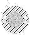
- the optical fiber cable 10 of the present embodiment includes a core 8 having a plurality of optical fibers 1a, inclusions 4, and a sheath 5 covering the core 8.
- the central axis of the sheath 5 is referred to as the central axis O
- the direction along the central axis O is referred to as the longitudinal direction
- the cross section orthogonal to the longitudinal direction is referred to as the cross section.
- the area in the cross section is called the cross-sectional area.
- the direction that intersects the central axis O is referred to as the radial direction
- the direction that orbits around the central axis O is referred to as the circumferential direction.
- the core 8 includes a plurality of optical fiber units 1 each having a plurality of optical fibers 1a, and a presser winding 2 for wrapping the optical fiber units 1.
- the plurality of optical fiber units 1 are wrapped by the presser winding 2 in a state of being twisted together in an SZ shape or a spiral shape.
- the plurality of optical fibers 1a included in each optical fiber unit 1 may or may not be twisted together in an SZ shape or a spiral shape.
- the core 8 may be configured by wrapping one optical fiber unit 1 with a presser winding 2.
- the presser roll 2 a non-woven fabric, polyester tape, or the like can be used. Further, as the presser roll 2, a water-absorbing tape obtained by imparting water absorption to a non-woven fabric, a polyester tape, or the like may be used. In this case, the waterproof performance of the optical fiber cable 10 can be improved.
- the core 8 does not have to be provided with the presser winding 2, and the optical fiber unit 1 may be in contact with the inclusions 4. In other words, the inclusions 4 may be used as the presser roll 2. However, when the presser winding 2 is provided, the optical fiber unit 1 is prevented from being disassembled during manufacturing, so that the core 8 can be more easily provided inside the sheath 5.
- the optical fiber unit 1 of the present embodiment includes a plurality of optical fibers 1a and a bundling material 1b for bundling these optical fibers 1a.
- an optical fiber core wire, an optical fiber wire, an optical fiber tape core wire, or the like can be used as the optical fiber 1a.
- the plurality of optical fibers 1a may form a so-called intermittent fixed tape core wire. In the intermittent fixing tape core wire, the plurality of optical fibers 1a are adhered to each other so as to spread in a mesh shape (spider web shape) when pulled in a direction orthogonal to the extending direction thereof.
- one optical fiber 1a is adhered to the adjacent optical fibers 1a at different positions in the longitudinal direction, and the adjacent optical fibers 1a are spaced apart from each other in the longitudinal direction. Are glued to each other.
- the mode of the optical fiber 1a included in the core 8 is not limited to the intermittent fixing tape core wire, and may be appropriately changed.
- the binding material 1b may be in the form of a string, in the form of a sheet, or in the form of a tube.
- the binding material 1b extends in the longitudinal direction and is arranged so as to bundle a plurality of optical fibers 1a included in one optical fiber unit. Further, the plurality of optical fibers 1a may be wrapped by the presser winding 2 as they are without being bundled (that is, without forming the optical fiber unit 1). Alternatively, a plurality of optical fibers 1a may be bundled by being twisted together to form an optical fiber unit 1. In this case, the optical fiber unit 1 does not have to have the binding material 1b.
- the cross-sectional shape of the optical fiber unit 1 is arranged in FIG. 1 and the like, the cross-sectional shape may be deformed due to the movement of the optical fiber 1a in the optical fiber unit 1.
- three optical fiber units 1 form an inner layer, and seven optical fiber units 1 form an outer layer. However, a part of the outer layer may enter the inner layer. Alternatively, the optical fiber unit 1 may not form these layers.
- a plurality of optical fiber units 1 are arranged with a uniform gap, but the gap may be eliminated or the gap may be non-uniform.
- an inclusion 4 may be inserted between the optical fiber units 1 to adjust the shape of the core 8.
- the optical fiber 1a has a glass portion 11, a primary layer 12, a secondary layer 13, and a colored layer 14.
- the glass portion 11 is formed of, for example, quartz-based glass and transmits light.
- the primary layer 12 is formed of a resin (for example, a UV curable resin) and covers the glass portion 11.
- the secondary layer 13 is formed of a resin (for example, a UV curable resin) and covers the primary layer 12.
- the colored layer 14 is formed of a colored resin (for example, a UV curable resin) and is arranged outside the primary layer 12 and the secondary layer 13.
- the colored layer 14 may not be provided. Further, the secondary layer 13 may be colored and the secondary layer 13 itself may be used as the colored layer.
- the specific materials of the primary layer 12, the secondary layer 13, and the colored layer 14 may be the same or different from each other.
- the UV curable resin for example, an acrylate resin or the like can be used.
- the ripcord 7 is a thread of synthetic fiber such as polyester, and is used for tearing the sheath 5. Further, as the ripcord 7, a columnar rod made of polypropylene (PP) or nylon may be used.
- PP polypropylene
- the sheath 5 covers the core 8.
- the sheath 5 has a storage space for accommodating the core 8.
- the accommodation space in the present embodiment is the entire region surrounded by the inner peripheral surface of the sheath 5.
- the material of the sheath 5 is a polyolefin (PO) such as polyethylene (PE), polypropylene (PP), ethylene ethyl acrylate copolymer (EEA), ethylene vinyl acetate copolymer (EVA), and ethylene propylene copolymer (EP).
- PO polyolefin
- PE polyethylene
- PP polypropylene
- EOA ethylene ethyl acrylate copolymer
- EVA ethylene vinyl acetate copolymer
- EP ethylene propylene copolymer
- Resin, polyvinyl chloride (PVC) and the like can be used. Further, a mixture of the above resins (alloy, mixture) may be used.
- a marking portion 5a for indicating the position of the ripcord 7 is provided on the outer peripheral surface of the sheath 5.
- the marking portion 5a may be a protrusion protruding outward in the radial direction as shown in FIG. 1, or may be marking with a paint or the like.
- the marking portion 5a since it is possible to grasp the position of the ripcord 7 by the bending direction of the optical fiber cable 10 brought about by the tensile strength body 6, the marking portion 5a may be omitted.
- the inclusions 4 are arranged inside the sheath 5 so as to be in contact with the optical fiber unit 1.
- the inclusions 4 may be in direct contact with the optical fiber 1a.
- the binding material 1b is tubular, the inclusions 4 may come into contact with the binding material 1b without contacting the optical fiber 1a.
- the inclusions 4 act as a cushion, and it is possible to suppress the occurrence of microbends in the optical fiber 1a. Further, the frictional force acting on the optical fiber unit 1 can be adjusted by the inclusions 4.
- the frictional force may act on the optical fiber 1a via the binding material 1b, or may act directly on the optical fiber 1a.
- any material can be adopted as long as it has a cushioning property.
- Specific examples of the material of the inclusions 4 include polyester fibers, aramid fibers, and glass fibers.
- the inclusions 4 may be composed of a yarn having water absorption or the like. In this case, the waterproof performance inside the optical fiber cable 10 can be enhanced.
- the optical fiber cable 10 is required to reduce the optical transmission loss while increasing the number of optical fibers 1a included as much as possible.
- the optical fiber 1a When the optical fiber 1a is mounted at a high density, microbend loss is likely to occur in the optical fiber 1a when a lateral pressure is applied to the optical fiber cable 10. Therefore, it is conceivable to reduce the density of the optical fiber 1a (for example, to increase the space in the sheath 5), but if the density of the optical fiber 1a is simply reduced, the frictional force acting on the optical fiber 1a is reduced. , The untwisting of the optical fiber 1a is likely to occur.
- the extra length ratio of the optical fiber 1a in the optical fiber cable 10 is insufficient, and the optical fiber 1a is stretched and distorted, leading to an increase in optical loss.
- the frictional force acting on the optical fiber 1a is too small, the optical fiber 1a may protrude from the end face of the sheath 5 beyond the allowable range at the end portion in the longitudinal direction of the optical fiber cable 10.
- the frictional force acting on the optical fiber 1a is a frictional force generated between the optical fiber 1a and a member in contact with the optical fiber 1a.
- the frictional force may be generated between adjacent optical fibers 1a and between the optical fiber 1a and another member in contact with the optical fiber 1a.
- Non-Patent Document 1 J. Baldauf, et al., “Relationship of Mechanical Characteristics of Dual Coated Single Mode Optical Fibers and Microbending Loss,” IEICE Trans. Commun., Vol. E76-B, No. 4, 1993.
- Non-Patent Document 2 K. Petermann, et al., “Upper and Lower Limits for the Microbending Loss in Arbitrary Single-Mode Fibers,” J. Lightwave technology, vol. LT-4, no.1, pp. 2-7 , 1986.
- Non-Patent Document 3 P. Sillard, et al., “Micro-Bend Losses of Trench-Assisted Single-Mode Fibers,” ECOC2010, We.8.F.3, 2010.
- the influence of the geometry of the optical fiber 1a on the microbend loss can be expressed by the geometry loss factor F ⁇ BL_G obtained from the following mathematical formula (1).
- the definition of each parameter is as follows.
- H f Flexural rigidity of the glass portion 11 of the optical fiber 1a (Pa ⁇ m 4 )
- D 0 Deformation resistance (Pa) of the secondary layer 13
- H 0 Flexural rigidity of the secondary layer 13 (Pa ⁇ m 4 )
- ⁇ Predetermined constant
- E p Young's modulus (MPa) of the primary layer 12
- d f Outer diameter ( ⁇ m) of the glass portion 11
- tp Thickness of primary layer 12 ( ⁇ m)
- E g Young's modulus (GPa) of the glass portion 11
- R s Radius ( ⁇ m) of the outer peripheral surface of the secondary layer 13.
- t s Thickness of secondary layer 13 ( ⁇ m)
- E s Young's modulus (MPa) of the secondary layer 13.
- R p Radius ( ⁇ m) of the outer peripheral surface of the primary layer 12
- t p R p ⁇ d f / 2
- t s R s ⁇ R p .
- the influence of the optical characteristics of the optical fiber 1a on the microbend loss can be expressed by the optical loss factor F ⁇ BL_ ⁇ obtained from the following mathematical formula (2).
- the definition of each parameter is as follows.
- ⁇ Difference between the propagation constant of the light propagating through the optical fiber 1a in the waveguide mode and the propagation constant in the radiation mode.
- the unit is (rad / m).
- the "radiation mode” is a mode one higher order than the waveguide mode in which the optical fiber 1a can propagate.
- p Predetermined constant
- Non-Patent Document 4 K. Kobayashi, et al., “Study of Microbending loss in thin coated fibers and fiber ribbons,” IWCS, pp.386-392, 1993.
- Non-Patent Document 2 the typical value of the constant p in the mathematical formula (2) is 4. Therefore, the mathematical formula (2) becomes the following mathematical formula (4).
- Non-Patent Document 5 C. D. Hussey, et al., “characterization and design of single-mode optical fiber,” Optical and Quantum Electronics, vol. 14, no. 4, pp. 347-358, 1982.
- the value of the optical loss factor F ⁇ BL_ ⁇ is inversely proportional to the eighth power of the propagation constant difference ⁇ . It is considered that the larger the geometry loss factor F ⁇ BL_G and the optical loss factor F ⁇ BL_ ⁇ derived from the equations (3) and (4), the larger the microbend loss of the optical fiber 1a.
- ⁇ of a general optical fiber (for example, compliant with ITU-T G.657.A1) is 9900 to 12000 (rad / m).
- low-loss optical fibers for long-distance transmission eg, ITU-T G.654.E compliant
- Microbend loss is more likely to occur as the optical fiber 1a is housed in the optical fiber cable 10 at a high density. The reason is that, for example, when the optical fiber cable 10 is bent, the optical fiber 1a is strongly pressed against the other optical fiber 1a, the presser winding 2, or the sheath 5, and the optical fiber 1a is slightly bent (microbend). Is likely to occur. If the inclusions 4 are appropriately arranged around the optical fiber 1a, the inclusions 4 act as a cushion, and microbend and microbend loss can be reduced. On the other hand, if the inclusions 4 are excessively filled in the optical fiber cable 10, the cushioning property of the inclusions 4 is lowered, and the microbend and the microbend loss cannot be effectively reduced.
- the microbend loss in order to reduce the microbend loss, it is required to appropriately set a substantial density in consideration of not only the mounting density of the simple optical fiber 1a but also the filling amount of the inclusions 4. Further, the microbend loss is affected not only by the filling amount of the inclusions 4 but also by the influence of the above-mentioned geometry and the value of ⁇ . Therefore, the inventors of the present application quantified the influence of various parameters of the optical fiber cable 10 on the microbend loss, and found the conditions for keeping the microbend loss below a certain level. Hereinafter, it will be described in detail with reference to Tables 1 and 2.
- the optical fiber cables 10 of Samples 1-1 to 1-22 were prepared.
- an intermittent fixing tape core wire twisted to each other was used as the optical fiber 1a.
- D1 is the mounting density of the optical fiber 1a (unit: [book / mm 2 ]) and is defined by the following mathematical formula (5).
- the definition of each parameter is as follows. N: Number of optical fibers 1a accommodated in the accommodation space in the sheath 5 (lines) S: Cross-sectional area of the accommodation space in the sheath 5 (mm 2 ) A: The sum of the cross-sectional areas of the members (excluding the optical fiber 1a) arranged in the accommodation space in the sheath 5 (mm 2 ).
- the value of A in the example of FIG. 1 is the sum of the cross-sectional areas of the presser roll 2, the binding material 1b, and the inclusions 4.
- the value of S in the example of FIG. 1 is the cross-sectional area of the region surrounded by the inner peripheral surface of the sheath 5.
- D2 is the mounting density of inclusions 4 (unit: [d / mm 2 ]) and is defined by the following mathematical formula (6).
- T is the total denier number of inclusions 4 in the containment space (unit: d: denier).
- C1 is a coefficient representing the effect of the mounting density D2 of the inclusions 4 on the microbend loss.
- C2 is a coefficient representing the effect of ⁇ of the optical fiber 1a on the microbend loss.
- C3 is a coefficient representing the influence of the geometry loss factor on the microbend loss.
- C4 is a coefficient representing the effect of the cushioning property of the inclusions 4 on the microbend loss.
- the coefficient C1 is derived from Table 4 and FIG. 4 below.
- Table 4 the optical fiber cables 10 of Samples 3-1 to 3-6 were prepared.
- the mounting density D1 of the optical fiber 1a was set to 10.6 (lines / mm 2 ).
- Samples 3-2 to 3-6 have the same number (N) of optical fibers 1a and the cross-sectional area (S) of the accommodation space in the sheath 5 as those of sample 3-1 but are filled with inclusions 4. Further, in the samples 3-2 to 3-6, the filling amounts of the inclusions 4 are different from each other. Therefore, the mounting densities D2 of the inclusions 4 are different from each other in the samples 3-1 to 3-6.
- Table 4 the transmission loss of each sample 3-1 to 3-6 was measured.
- D1' is the apparent mounting density of the optical fiber 1a obtained by applying the measurement result of the transmission loss to the above conversion formula.
- D1 actual mounting density of the optical fiber 1a
- D1' the value of D1'(the influence of inclusions 4 are taken into consideration).
- the apparent mounting density of the optical fiber 1a) is equal to.
- the transmission loss (0.220 dB / km) of sample 3-2 is substituted as the value of y in the above conversion formula, the value of x becomes 10.3.
- the value of x thus obtained is the apparent mounting density D1'of the optical fiber 1a.
- the horizontal axis of FIG. 4 is “D2” in Table 4, and the vertical axis of FIG. 4 is the “relative ratio” of Table 4.
- the coefficient C1 calculated by the mathematical formula (7) is a numerical value of the influence of the mounting density D2 of the inclusions 4 on the microbend loss.
- the coefficient C2 is derived from Table 5 and FIG. 5 below.
- Table 5 the optical fiber cables 10 of Samples 4-1 to 4-7 were prepared. Each sample 4-1 to 4-7 has a different value of ⁇ .
- the column of " ⁇ - 8 " indicates the value of ⁇ to the -8th power of each sample. Using the value of ⁇ to the -8th power is based on the above-mentioned mathematical formula (4).
- the upper limit of the mounting density of the optical fiber 1a for the transmission loss value to be 0.23 dB / km or less is shown for each sample.
- the column of "relative ratio” the ratio based on "11 lines / mm 2 ", which is the mounting density of the optical fiber 1a of a general optical fiber cable, is shown.
- the horizontal axis of FIG. 5 is “ ⁇ - 8 ” in Table 5, and the vertical axis of FIG. 5 is the “relative ratio” of Table 5. Similar to the derivation process for the coefficient C1, when the value of y in the approximate expression of the graph of FIG. 5 is the coefficient C2 and the value of x is ⁇ - 8 , the following equation (8) is obtained.
- the coefficient C2 calculated by the equation (8) converts the value of ⁇ into the apparent mounting density of the optical fiber 1a.
- the coefficient C3 is derived from Table 6 and FIG. 6 below.
- Table 6 the optical fiber cables 10 of the samples 5-1 to 5-5 were prepared.
- Each sample 5-1 to 5-5 has a common value of ⁇ at 9350 (rad / m), but the value of the geometry loss factor F ⁇ BL_G is different due to the difference in the design of the primary layer 12 and the secondary layer 13. Different from each other.
- the meaning of D1'' in Table 6 is the same as that in Table 5.
- the ratio based on the value of the sample 5-5 having the smallest value of the geometry loss factor F ⁇ BL_G that is, the least occurrence of microbend loss
- the horizontal axis of FIG. 6 is “F ⁇ BL_G ” in Table 6, and the vertical axis of FIG. 6 is the “relative ratio” of Table 6.
- the coefficient C1 Similar to the derivation process for the coefficient C1, when the value of y in the approximate expression of the graph of FIG. 6 is the coefficient C3 and the value of x is F ⁇ BL_G , the following mathematical formula (9) is obtained.
- the coefficient C3 calculated by the equation (9) converts the value of F ⁇ BL_G into the apparent mounting density of the optical fiber 1a.
- the coefficient C4 is derived from Table 7 and FIG. 7 below. As shown in Table 7, the optical fiber cables 10 of Samples 6-1 to 6-6 were prepared. Each sample 6-1 to 6-6 is designed so that the filling amount of the inclusions 4 is different from each other, but the mounting density D1 of the optical fiber 1a is the same. When D1 is the same, the larger the filling amount of the inclusions 4, the higher the cushioning property, and the lower the transmission loss. Similar to the process of deriving the coefficient C1, the transmission loss of each sample was measured, and the apparent mounting density D1'of the optical fiber 1a was calculated using the above-mentioned conversion formula. The "relative ratio" is the ratio of the values of D1'based on the sample 6-1 not filled with the inclusions 4.
- the horizontal axis of FIG. 7 is “D2” in Table 7, and the vertical axis of FIG. 7 is the “relative ratio” of Table 7.
- the coefficient C1 Similar to the process of deriving the coefficient C1, when the value of y in the approximate expression of the graph of FIG. 7 is C4 and the value of x is D2, the following mathematical formula (10) is obtained.
- the coefficient C4 calculated by the equation (10) converts the cushioning property of the inclusions 4 into the apparent mounting density of the optical fiber 1a.
- the optical fiber cable 10 proposed by the inventors of the present application includes a sheath 5 and a core 8 having a plurality of optical fibers 1a housed in a housed space in the sheath 5 in a twisted state.
- Each of the plurality of optical fibers 1a has a glass portion 11, a primary layer 12 covering the glass portion 11, and a secondary layer 13 covering the primary layer 12, and the value of the index Q is less than 20.
- the core wire pulling force when pulling out the fiber 1a is 15 N / 10 m or more.
- the index Q is less than 20 and the core wire drawing force is 15 N / 10 m or more. It is possible to meet the conditions. Therefore, the inclusions 4 may or may not be located inside the sheath 5.
- the value of the index Q is set to less than 20 and the index Q is set to less than 20. It is considered that the same effect can be obtained by setting the value of the core wire pulling force to 15 N / 10 m or more. Further, the presser winding 2 may be omitted. In this case, the value of A in the formula (5) does not include the cross-sectional area of the presser winding 2.
- the entire region surrounded by the inner peripheral surface of the sheath 5 is used as the accommodation space.
- the core 8 includes a slot member having a plurality of grooves (slots) formed therein, and the optical fiber 1a is accommodated in the groove in a twisted state. Therefore, the inside of the groove of the slot member is the accommodation space, N in the mathematical formula (5) is the number of optical fibers 1a accommodated in the groove, and S is the cross-sectional area inside the groove.
- the core 8 includes a plurality of loose tubes, and the optical fiber 1a is housed in the loose tube in a twisted state. Therefore, the inside of the loose tube is the accommodation space, N in the formula (5) is the number of optical fibers 1a accommodated in the loose tube, and S is the cross-sectional area inside the loose tube.
- optical fiber cable 1a ... optical fiber 2 ... presser winding 4 ... inclusions 5 ... sheath 8 ... core 10 ... optical fiber cable
Landscapes
- Physics & Mathematics (AREA)
- General Physics & Mathematics (AREA)
- Optics & Photonics (AREA)
- Light Guides In General And Applications Therefor (AREA)
- Communication Cables (AREA)
- Optical Fibers, Optical Fiber Cores, And Optical Fiber Bundles (AREA)
- Insulated Conductors (AREA)
Priority Applications (6)
| Application Number | Priority Date | Filing Date | Title |
|---|---|---|---|
| US18/016,115 US20230273381A1 (en) | 2020-09-02 | 2021-08-25 | Optical fiber cable |
| JP2022546267A JPWO2022050152A1 (https=) | 2020-09-02 | 2021-08-25 | |
| CN202180043054.4A CN115698808A (zh) | 2020-09-02 | 2021-08-25 | 光纤缆线 |
| AU2021335442A AU2021335442A1 (en) | 2020-09-02 | 2021-08-25 | Optical fiber cable |
| EP21864210.6A EP4209813A1 (en) | 2020-09-02 | 2021-08-25 | Optical fiber cable |
| CA3187252A CA3187252A1 (en) | 2020-09-02 | 2021-08-25 | Optical fiber cable |
Applications Claiming Priority (2)
| Application Number | Priority Date | Filing Date | Title |
|---|---|---|---|
| JP2020-147729 | 2020-09-02 | ||
| JP2020147729 | 2020-09-02 |
Publications (1)
| Publication Number | Publication Date |
|---|---|
| WO2022050152A1 true WO2022050152A1 (ja) | 2022-03-10 |
Family
ID=80490931
Family Applications (1)
| Application Number | Title | Priority Date | Filing Date |
|---|---|---|---|
| PCT/JP2021/031193 Ceased WO2022050152A1 (ja) | 2020-09-02 | 2021-08-25 | 光ファイバケーブル |
Country Status (8)
| Country | Link |
|---|---|
| US (1) | US20230273381A1 (https=) |
| EP (1) | EP4209813A1 (https=) |
| JP (1) | JPWO2022050152A1 (https=) |
| CN (1) | CN115698808A (https=) |
| AU (1) | AU2021335442A1 (https=) |
| CA (1) | CA3187252A1 (https=) |
| TW (1) | TWI779807B (https=) |
| WO (1) | WO2022050152A1 (https=) |
Cited By (2)
| Publication number | Priority date | Publication date | Assignee | Title |
|---|---|---|---|---|
| JP2024086151A (ja) * | 2022-12-16 | 2024-06-27 | 住友電気工業株式会社 | 光ファイバケーブル |
| WO2025263539A1 (ja) * | 2024-06-21 | 2025-12-26 | 住友電気工業株式会社 | 光ファイバケーブル |
Families Citing this family (2)
| Publication number | Priority date | Publication date | Assignee | Title |
|---|---|---|---|---|
| EP4427083A4 (en) * | 2021-11-05 | 2025-10-08 | Corning Res & Dev Corp | HIGH FIBER DENSITY FIBER OPTIC CABLE |
| US20240353639A1 (en) * | 2021-12-10 | 2024-10-24 | Sumitomo Electric Industries, Ltd. | Optical fiber cable and method for manufacturing optical fiber cable |
Citations (8)
| Publication number | Priority date | Publication date | Assignee | Title |
|---|---|---|---|---|
| JP2000131571A (ja) * | 1998-10-28 | 2000-05-12 | Sumitomo Electric Ind Ltd | 光ファイバケーブル |
| US20050013573A1 (en) * | 2003-07-18 | 2005-01-20 | Lochkovic Gregory A. | Fiber optic articles, assemblies, and cables having optical waveguides |
| JP2010217392A (ja) * | 2009-03-16 | 2010-09-30 | Fujikura Ltd | 光ファイバケーブル |
| JP2014139609A (ja) | 2013-01-21 | 2014-07-31 | Fujikura Ltd | 光ファイバケーブル |
| JP2015131733A (ja) * | 2014-01-09 | 2015-07-23 | 住友電気工業株式会社 | 光ファイバおよび光ケーブル |
| JP2018081328A (ja) * | 2016-04-01 | 2018-05-24 | 株式会社フジクラ | 光ファイバ |
| JP2019031422A (ja) * | 2017-08-09 | 2019-02-28 | 株式会社フジクラ | 光ファイバ素線の製造方法および光ファイバ素線 |
| JP2020147729A (ja) | 2019-03-15 | 2020-09-17 | 横浜ゴム株式会社 | セミコンティニアスマリンホース用ゴム組成物及びセミコンティニアスマリンホース |
Family Cites Families (4)
| Publication number | Priority date | Publication date | Assignee | Title |
|---|---|---|---|---|
| KR100526506B1 (ko) * | 2003-05-27 | 2005-11-08 | 삼성전자주식회사 | 공기압 포설을 위한 광섬유 케이블 |
| US8989543B2 (en) * | 2011-11-17 | 2015-03-24 | Sumitomo Electric Industries, Ltd. | Optical cable |
| US10458191B2 (en) * | 2013-12-28 | 2019-10-29 | Trican Well Service, Ltd. | Carbon fiber based tubing encapsulated cable |
| TWM594154U (zh) * | 2019-09-18 | 2020-04-21 | 光元先進科技股份有限公司 | 加強型光纖纜線 |
-
2021
- 2021-08-25 AU AU2021335442A patent/AU2021335442A1/en not_active Abandoned
- 2021-08-25 WO PCT/JP2021/031193 patent/WO2022050152A1/ja not_active Ceased
- 2021-08-25 CN CN202180043054.4A patent/CN115698808A/zh active Pending
- 2021-08-25 US US18/016,115 patent/US20230273381A1/en not_active Abandoned
- 2021-08-25 EP EP21864210.6A patent/EP4209813A1/en not_active Withdrawn
- 2021-08-25 CA CA3187252A patent/CA3187252A1/en active Pending
- 2021-08-25 JP JP2022546267A patent/JPWO2022050152A1/ja active Pending
- 2021-08-30 TW TW110132111A patent/TWI779807B/zh not_active IP Right Cessation
Patent Citations (8)
| Publication number | Priority date | Publication date | Assignee | Title |
|---|---|---|---|---|
| JP2000131571A (ja) * | 1998-10-28 | 2000-05-12 | Sumitomo Electric Ind Ltd | 光ファイバケーブル |
| US20050013573A1 (en) * | 2003-07-18 | 2005-01-20 | Lochkovic Gregory A. | Fiber optic articles, assemblies, and cables having optical waveguides |
| JP2010217392A (ja) * | 2009-03-16 | 2010-09-30 | Fujikura Ltd | 光ファイバケーブル |
| JP2014139609A (ja) | 2013-01-21 | 2014-07-31 | Fujikura Ltd | 光ファイバケーブル |
| JP2015131733A (ja) * | 2014-01-09 | 2015-07-23 | 住友電気工業株式会社 | 光ファイバおよび光ケーブル |
| JP2018081328A (ja) * | 2016-04-01 | 2018-05-24 | 株式会社フジクラ | 光ファイバ |
| JP2019031422A (ja) * | 2017-08-09 | 2019-02-28 | 株式会社フジクラ | 光ファイバ素線の製造方法および光ファイバ素線 |
| JP2020147729A (ja) | 2019-03-15 | 2020-09-17 | 横浜ゴム株式会社 | セミコンティニアスマリンホース用ゴム組成物及びセミコンティニアスマリンホース |
Non-Patent Citations (5)
| Title |
|---|
| C. D. HUSSEY ET AL.: "Characterization and design of single-mode optical fibres", OPTICAL AND QUANTUM ELECTRONICS, vol. 14, no. 4, 1982, pages 347 - 358 |
| J. BALDAUF ET AL.: "Relationship of Mechanical Characteristics of Dual Coated Single Mode Optical Fibers and Microbending Loss", IEICE TRANS. COMMUN., no. 4, 1993, XP000378265 |
| K. KOBAYASHI ET AL.: "Study of Microbending loss in thin coated fibers and fiber ribbons", IWCS, pages 386,392 |
| K. PETERMANN ET AL.: "Upper and Lower Limits for the Microbending Loss in Arbitrary Single-Mode Fibers", J. LIGHTWAVE TECHNOLOGY, no. 1, 1986, pages 2 - 7, XP055863843, DOI: 10.1109/JLT.1986.1074620 |
| P. SILLARD ET AL.: "Micro-Bend Losses of Trench-Assisted Single-Mode Fibers", ECOC2010, 2010 |
Cited By (2)
| Publication number | Priority date | Publication date | Assignee | Title |
|---|---|---|---|---|
| JP2024086151A (ja) * | 2022-12-16 | 2024-06-27 | 住友電気工業株式会社 | 光ファイバケーブル |
| WO2025263539A1 (ja) * | 2024-06-21 | 2025-12-26 | 住友電気工業株式会社 | 光ファイバケーブル |
Also Published As
| Publication number | Publication date |
|---|---|
| AU2021335442A1 (en) | 2023-02-23 |
| TW202227868A (zh) | 2022-07-16 |
| CN115698808A (zh) | 2023-02-03 |
| CA3187252A1 (en) | 2022-03-10 |
| TWI779807B (zh) | 2022-10-01 |
| EP4209813A1 (en) | 2023-07-12 |
| JPWO2022050152A1 (https=) | 2022-03-10 |
| US20230273381A1 (en) | 2023-08-31 |
Similar Documents
| Publication | Publication Date | Title |
|---|---|---|
| WO2022050152A1 (ja) | 光ファイバケーブル | |
| US7254303B2 (en) | Optical tube assembly having a dry insert and methods of making the same | |
| US6785450B2 (en) | Self-supporting fiber optic cable | |
| CN101770056B (zh) | 包括穿孔的阻水元件的光纤电缆 | |
| US8682123B2 (en) | Adhesively coupled optical fibers and enclosing tape | |
| US9964724B2 (en) | Fiber optic ribbon cable having enhanced ribbon stack coupling and methods thereof | |
| US6714708B2 (en) | Fiber optic with high strength component | |
| AU2008244628B2 (en) | Tubeless fiber optic cable having torque balanced strength members | |
| EP1489447B1 (en) | A fiber optic cable having no rigid strength members and a reduced coefficient of thermal expansion | |
| US7336873B2 (en) | Optical tube assembly having a dry insert and methods of making the same | |
| US8380030B2 (en) | Bend-insensitive optical cable | |
| US11042000B2 (en) | Optical cable for terrestrial networks | |
| JP7800448B2 (ja) | 光ファイバケーブル及びコネクタ付きケーブル | |
| AU2009210359A1 (en) | Optical cable with stranded micromodules and apparatus to manufacture optical cable | |
| WO2015195095A1 (en) | Central-tube optical-fiber cable | |
| US9075215B2 (en) | Duplex cables and zipcord cables and breakout cables incorporating duplex cables | |
| US20250004194A1 (en) | Optical Fiber and Optical Fiber Cable | |
| GB1584457A (en) | Optical cables |
Legal Events
| Date | Code | Title | Description |
|---|---|---|---|
| 121 | Ep: the epo has been informed by wipo that ep was designated in this application |
Ref document number: 21864210 Country of ref document: EP Kind code of ref document: A1 |
|
| ENP | Entry into the national phase |
Ref document number: 2022546267 Country of ref document: JP Kind code of ref document: A |
|
| ENP | Entry into the national phase |
Ref document number: 3187252 Country of ref document: CA |
|
| ENP | Entry into the national phase |
Ref document number: 2021335442 Country of ref document: AU Date of ref document: 20210825 Kind code of ref document: A |
|
| NENP | Non-entry into the national phase |
Ref country code: DE |
|
| ENP | Entry into the national phase |
Ref document number: 2021864210 Country of ref document: EP Effective date: 20230403 |